Technical Publication - commscope.com · Installation Guidelines - – HELIAX ... END 1 (RRU/BBU)...
12
www.commscope.com/andrew • 1-800-255-1479 Bulletin # 7688580 Rev. D Technical Publication Related Support and Learning Opportunities Offered by the CommScope Infrastructure Academy The insights and expertise contained in this manual represent just one small part of Andrew Solutions global learning initiative. Few industries are evolving as quickly as wireless communications. Every technological innovation impacts what happens in the field. Our customers look to the CommScope Infrastructure Academy to make sure their technicians and installers are well trained, well-prepared, and well-educated to take advantage of opportunities as they evolve. To access a course, go to www.commscopetraining.com/coursecatalog.php, course #6107 Field Engineering Services (FES) Support services, such as our Field Engineering Services (FES) Group gives Andrew Solutions’ customers access to technical support where and when it is needed the most — in the field. The FES team is staffed by an expert team of technicians who, in turn, are supported by some of the brightest and most experienced product line managers. With all of this knowledge and support the FES offers our customers access to hands-on, specialized training classes. Section 1: Trunk Fiber Feeder Hoisting .......……………………………………………………………………….…02 Section 2: General Specifications / Fiber Jumpers....................…………………………………………..………04 Section 3: Trunk to Enclosure Connection .............……..…………………………………………………..………06 Section 4: Breakout Procedure / LC Connection Considerations ...…..……….…………………………….....07 Section 5: Cleaning / Inspecting ......……………………..…………………………………………………..………08 Section 6: BBU Breakout / Hanger- Grommet....…...........................................................………………………09 Section 7: Estimating Trunk Length / Excess Cable handling ...........……………….……………………..……10 Section 8: Installation Check List and Fiber Troubleshooting ……………………………………………….……12 Customer Service Center United States and Mexico 1-800-255-1479 or 1-888-235-5732 International: +1-779-435-8579 For the most current, up-to-date information on all our products and product information please visit our eCatalog section at www.commscope.com. Installation Guidelines - – HELIAX ® FiberFeed ® Hybrid Solutions Fiber/Copper Cables: RFA808, RFA810, RFA812, RFA412 1
Transcript of Technical Publication - commscope.com · Installation Guidelines - – HELIAX ... END 1 (RRU/BBU)...
www.commscope.com/andrew • 1-800-255-1479 Bulletin # 7688580 Rev. D
Technical Publication
Related Support and Learning Opportunities Offered by the CommScope Infrastructure Academy
The insights and expertise contained in this manual represent just one small part of Andrew Solutions global learning initiative. Few industries are evolving as quickly as wireless communications. Every technological innovation impacts what happens in the field. Our customers look to the CommScope Infrastructure Academy to make sure their technicians and installers are well trained, well-prepared, and well-educated to take advantage of opportunities as they evolve. To access a course, go to www.commscopetraining.com/coursecatalog.php, course #6107
Field Engineering Services (FES)
Support services, such as our Field Engineering Services (FES) Group gives Andrew Solutions’ customers access to technical support where and when it is needed the most — in the field. The FES team is staffed by an expert team of technicians who, in turn, are supported by some of the brightest and most experienced product line managers. With all of this knowledge and support the FES offers our customers access to hands-on, specialized training classes.
Section 1: Trunk Fiber Feeder Hoisting .......……………………………………………………………………….…02
Section 2: General Specifications / Fiber Jumpers....................…………………………………………..………04
Section 3: Trunk to Enclosure Connection .............……..…………………………………………………..………06
Section 4: Breakout Procedure / LC Connection Considerations ...…..……….…………………………….....07
Section 5: Cleaning / Inspecting ......……………………..…………………………………………………..………08
Section 6: BBU Breakout / Hanger- Grommet....…...........................................................………………………09
Section 7: Estimating Trunk Length / Excess Cable handling ...........……………….……………………..……10
Section 8: Installation Check List and Fiber Troubleshooting ……………………………………………….……12
Customer Service Center
United States and Mexico 1-800-255-1479 or 1-888-235-5732 International: +1-779-435-8579
For the most current, up-to-date information on all our products and product information please visit our eCatalog section at www.commscope.com.
Installation Guidelines - – HELIAX® FiberFeed® Hybrid Solutions Fiber/Copper Cables: RFA808, RFA810, RFA812, RFA412
1
www.commscope.com/andrew • 1-800-255-1479 Bulletin # 7688580 Rev. D
Technical Publication (Continued)
2
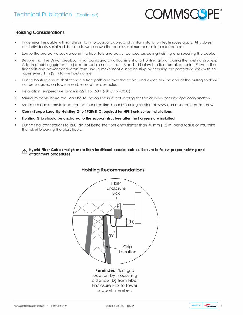
Reminder: Plan grip location by measuring distance (D) from Fiber Enclosure Box to tower
support member.
(D)
(D)
Fiber Enclosure
Box
Grip Location
Hoisting Considerations
Hoisting Recommendations
• In general this cable will handle similarly to coaxial cable, and similar installation techniques apply. All cables are individually serialized, be sure to write down the cable serial number for future reference.
• Leave the protective sock around the fiber tails and power conductors during hoisting and securing the cable.
• Be sure that the Direct breakout is not damaged by attachment of a hoisting grip or during the hoisting process. Attach a hoisting grip on the jacketed cable no less than .3 m (1 ft) below the fiber breakout point. Prevent the fiber tails and power conductors from undue movement during hoisting by securing the protective sock with tie ropes every 1 m (3 ft) to the hoisting line.
• During hoisting ensure that there is a free path and that the cable, and especially the end of the pulling sock will not be snagged on tower members or other obstacles.
• Installation temperature range is -22 F to 158 F (-30 C to +70 C).
• Minimum cable bend radii can be found on-line in our eCatalog section at www.commscope.com/andrew.
• Maximum cable tensile load can be found on-line in our eCatalog section at www.commscope.com/andrew.
• CommScope Lace-Up Hoisting Grip 19256B-C required for HFE trunk-series installations.
• Hoisting Grip should be anchored to the support structure after the hangers are installed.
• During final connections to RRU, do not bend the fiber ends tighter than 30 mm (1.2 in) bend radius or you take the risk of breaking the glass fibers.
Hybrid Fiber Cables weigh more than traditional coaxial cables. Be sure to follow proper hoisting and attachment procedures.!
www.commscope.com/andrew • 1-800-255-1479 Bulletin # 7688580 Rev. D
Technical Publication (Continued)
3
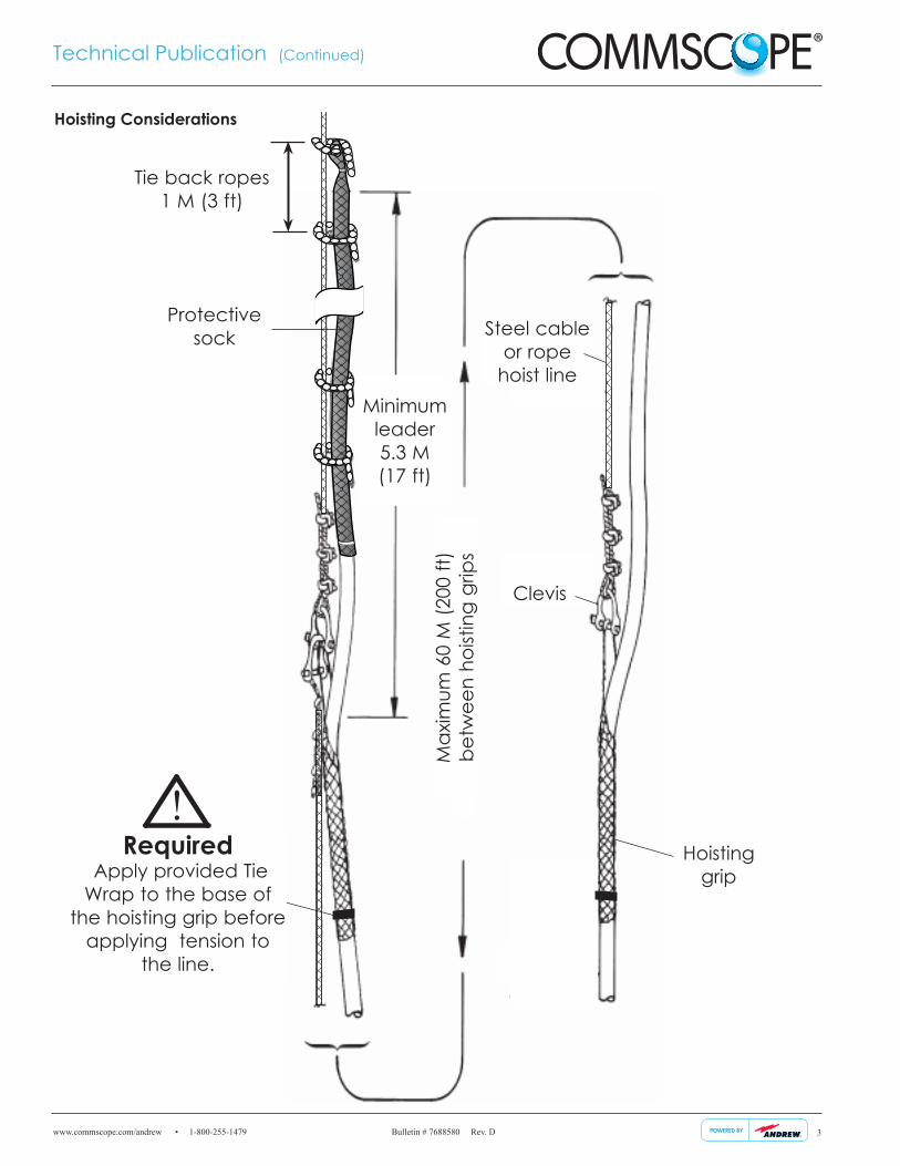
Required Apply provided Tie Wrap to the base of
the hoisting grip before applying tension to
the line.
!
Clevis
Steel cable or rope
hoist line
Hoisting grip
Minimum
leader 5.3 M (17 ft)
Max
imum
60
M (2
00 ft
) be
twee
n ho
istin
g gr
ips
Protective sock
Hoisting Considerations
Tie back ropes 1 M (3 ft)
www.commscope.com/andrew • 1-800-255-1479 Bulletin # 7688580 Rev. D
Technical Publication (Continued)
4
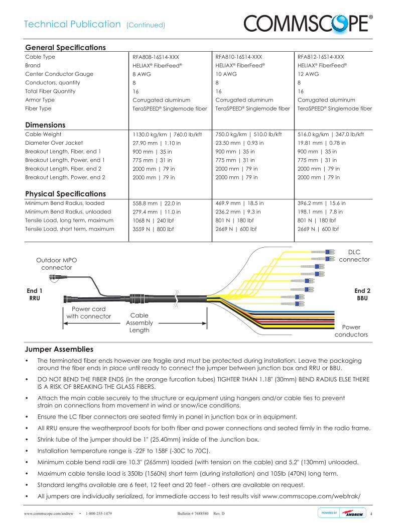
• The terminated fiber ends however are fragile and must be protected during installation. Leave the packaging around the fiber ends in place until ready to connect the jumper between junction box and RRU or BBU.
• DO NOT BEND THE FIBER ENDS (in the orange furcation tubes) TIGHTER THAN 1.18" (30mm) BEND RADIUS ELSE THERE IS A RISK OF BREAKING THE GLASS FIBERS.
• Attach the main cable securely to the structure or equipment using hangers and/or cable ties to prevent strain on connections from movement in wind or snow/ice conditions.
• Ensure the LC fiber connectors are seated firmly in panel in junction box or in equipment.
• All RRU ensure the weatherproof boots for both fiber and power connections and seated firmly in the radio frame.
• Shrink tube of the jumper should be 1" (25.40mm) inside of the Junction box.
• Installation temperature range is -22F to 158F (-30C to 70C).
• Minimum cable bend radii are 10.3" (265mm) loaded (with tension on the cable) and 5.2" (130mm) unloaded.
• Maximum cable tensile load is 350lb (1560N) short term (during installation) and 105lb (470N) long term.
• Standard lengths available are 6 feet, 12 feet and 20 feet - others are available on request.
• All jumpers are individually serialized, for immediate access to test results visit www.commscope.com/webtrak/
Jumper Assemblies
RFA808-16S14-XXXHELIAX® FiberFeed® 8 AWG8 16Corrugated aluminumTeraSPEED® Singlemode fiber
1130.0 kg/km | 760.0 lb/kft 27.90 mm | 1.10 in 900 mm | 35 in775 mm | 31 in 2000 mm | 79 in 2000 mm | 79 in
558.8 mm | 22.0 in 279.4 mm | 11.0 in 1068 N | 240 lbf 3559 N | 800 lbf
General Specifications Cable Type Brand Center Conductor Gauge Conductors, quantityTotal Fiber Quantity Armor TypeFiber Type
DimensionsCable Weight Diameter Over Jacket Breakout Length, Fiber, end 1Breakout Length, Power, end 1 Breakout Length, Fiber, end 2Breakout Length, Power, end 2
Physical SpecificationsMinimum Bend Radius, loaded Minimum Bend Radius, unloaded Tensile Load, long term, maximum Tensile Load, short term, maximum
RFA810-16S14-XXXHELIAX® FiberFeed® 10 AWG8 16Corrugated aluminumTeraSPEED® Singlemode fiber
750.0 kg/km | 510.0 lb/kft 23.50 mm | 0.93 in 900 mm | 35 in775 mm | 31 in 2000 mm | 79 in 2000 mm | 79 in
469.9 mm | 18.5 in 236.2 mm | 9.3 in 801 N | 180 lbf 2669 N | 600 lbf
RFA812-16S14-XXXHELIAX® FiberFeed® 12 AWG8 16Corrugated aluminumTeraSPEED® Singlemode fiber
516.0 kg/km | 347.0 lb/kft 19.81 mm | 0.78 in 900 mm | 35 in775 mm | 31 in 2000 mm | 79 in 2000 mm | 79 in
396.2 mm | 15.6 in 198.1 mm | 7.8 in 801 N | 180 lbf 2669 N | 600 lbf
Outdoor MPO connector
DLC connector
End 1 RRU
End 2 BBU
Cable Assembly
Length
Power cord with connector
Power conductors
www.commscope.com/andrew • 1-800-255-1479 Bulletin # 7688580 Rev. D
Technical Publication (Continued)
5
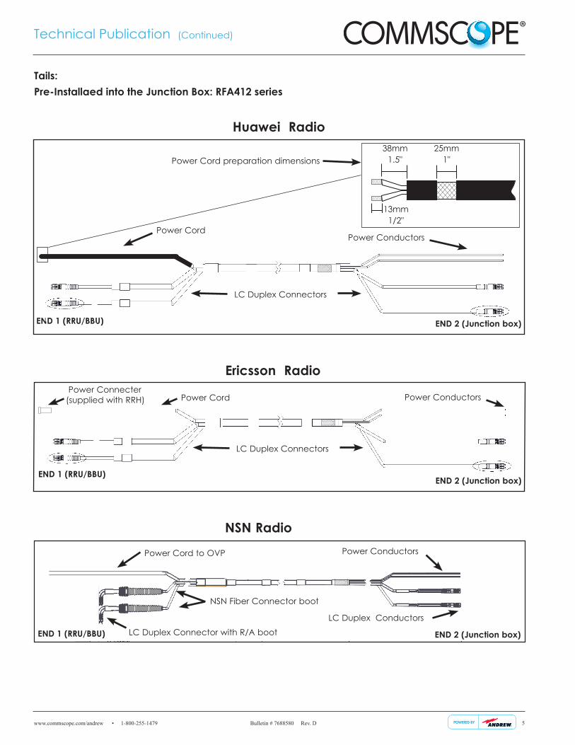
Power Cord Power Conductors
LC Duplex Connectors
END 1 (RRU/BBU)END 2 (Junction box)
Ericsson Radio Power Connecter (supplied with RRH)
NSN Radio
Power Cord to OVP
LC Duplex Connector with R/A boot
NSN Fiber Connector boot
END 1 (RRU/BBU)
Power Conductors
LC Duplex Conductors
END 2 (Junction box)
Power CordPower Conductors
LC Duplex Connectors
END 1 (RRU/BBU) END 2 (Junction box)
Huawei Radio
Power Cord preparation dimensions38mm
1.5"25mm
1"
13mm1/2"
Tails:Pre-Installaed into the Junction Box: RFA412 series
www.commscope.com/andrew • 1-800-255-1479 Bulletin # 7688580 Rev. D
Technical Publication (Continued)
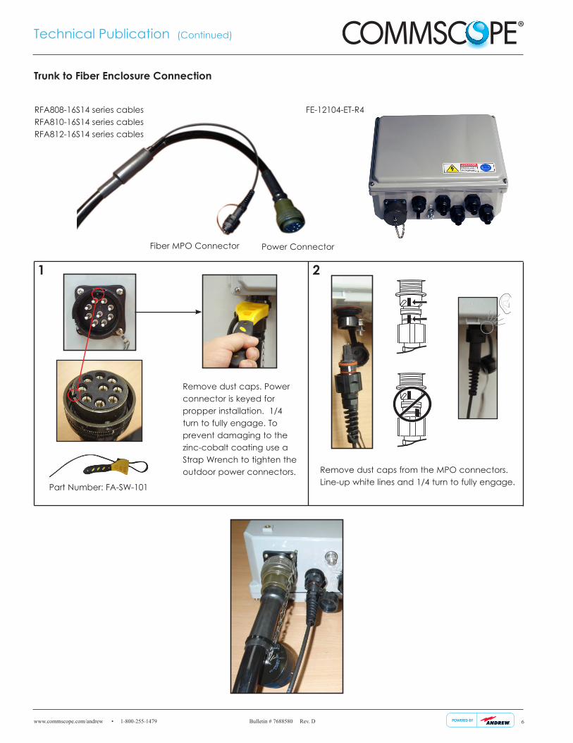
Fiber MPO Connector Power Connector
Remove dust caps. Power connector is keyed for propper installation. 1/4 turn to fully engage. To prevent damaging to the zinc-cobalt coating use a Strap Wrench to tighten the outdoor power connectors.
Part Number: FA-SW-101
Trunk to Fiber Enclosure Connection
FE-12104-ET-R4RFA808-16S14 series cables RFA810-16S14 series cables RFA812-16S14 series cables
Remove dust caps from the MPO connectors. Line-up white lines and 1/4 turn to fully engage.
1 2
6
www.commscope.com/andrew • 1-800-255-1479 Bulletin # 7688580 Rev. D
Technical Publication (Continued)
7
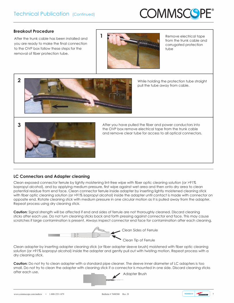
LC Connectors and Adapter cleaningClean exposed connector ferrule by lightly moistening lint-free wipe with fiber optic cleaning solution (or >91% isopropyl alcohol), and by applying medium pressure, first wipe against wet area and then onto dry area to clean potential residue from end face. Clean connector ferrule inside adapter by inserting lightly moistened cleaning stick with fiber optic cleaning solution (or >91% isopropyl alcohol) inside the adapter until contact is made with connector on opposite end. Rotate cleaning stick with medium pressure in one circular motion as it is pulled away from the adapter. Repeat process using dry cleaning stick.
Caution: Signal strength will be affected if end and sides of ferrule are not thoroughly cleaned. Discard cleaning sticks after each use. Do not turn cleaning sticks back and forth pressing against connector end face. This may cause scratches if large contamination is present. Always inspect connector end face for contamination after each cleaning.
Clean adapter by inserting adapter cleaning stick (or fiber adapter sleeve brush) moistened with fiber optic cleaning solution (or >91% isopropyl alcohol) inside the adapter and gently pull out with twisting motion. Repeat process with a dry cleaning stick.
Caution: Do not try to clean adapter with a standard pipe cleaner. The sleeve inner diameter of LC adapters is too small. Do not try to clean the adapter with cleaning stick if a connector is mounted in one side. Discard cleaning sticks after each use.
Clean Tip of Ferrule
Clean Sides of Ferrule
Adapter Brush
Breakout ProcedureRemove electrical tape from the trunk cable and corrugated protection tube
1
2
3
While holding the protection tube straight pull the tube away from cable.
After you have pulled the fiber and power conductors into the OVP box remove electrical tape from the trunk cable and remove clear tube for access to all optical connectors.
After the trunk cable has been installed and you are ready to make the final connection to the OVP box follow these steps for the removal of fiber protection tube.
www.commscope.com/andrew • 1-800-255-1479 Bulletin # 7688580 Rev. D
Technical Publication (Continued)
8
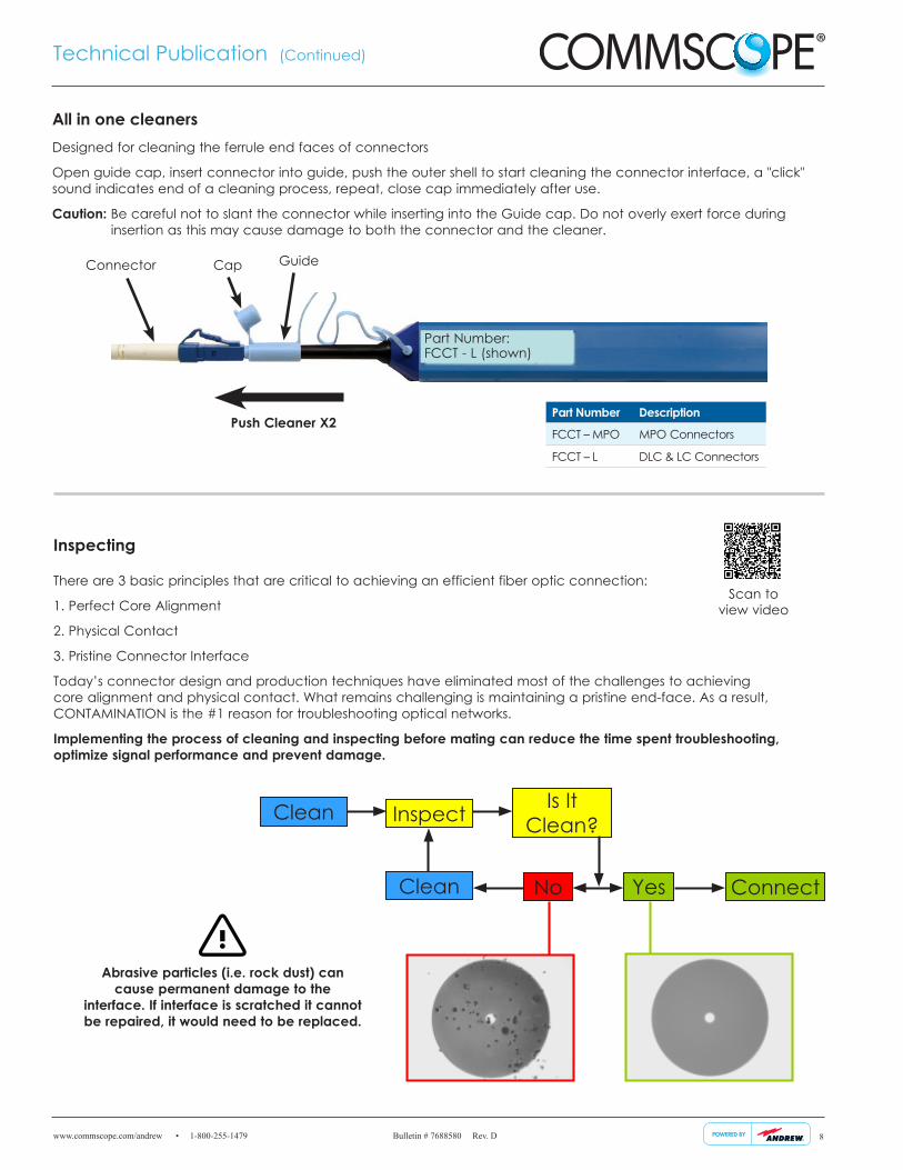
There are 3 basic principles that are critical to achieving an efficient fiber optic connection:
1. Perfect Core Alignment
2. Physical Contact
3. Pristine Connector Interface
Today’s connector design and production techniques have eliminated most of the challenges to achieving core alignment and physical contact. What remains challenging is maintaining a pristine end-face. As a result, CONTAMINATION is the #1 reason for troubleshooting optical networks.
Implementing the process of cleaning and inspecting before mating can reduce the time spent troubleshooting, optimize signal performance and prevent damage.
Inspecting
Is It Clean?
No ConnectYes
Inspect
Clean
Clean
Abrasive particles (i.e. rock dust) can cause permanent damage to the
interface. If interface is scratched it cannot be repaired, it would need to be replaced.
Scan to view video
Designed for cleaning the ferrule end faces of connectors
Open guide cap, insert connector into guide, push the outer shell to start cleaning the connector interface, a "click" sound indicates end of a cleaning process, repeat, close cap immediately after use.
Caution: Be careful not to slant the connector while inserting into the Guide cap. Do not overly exert force during insertion as this may cause damage to both the connector and the cleaner.
All in one cleaners
GuideConnector
Push Cleaner X2
Cap
Part Number Description
FCCT – MPO MPO Connectors
FCCT – L DLC & LC Connectors
Part Number: FCCT - L (shown)
www.commscope.com/andrew • 1-800-255-1479 Bulletin # 7688580 Rev. D
Technical Publication (Continued)
#1
#2
#3
#4
#1
#2
#3
#4
#1#
2
#3#
4
#5#
6
#7#
8
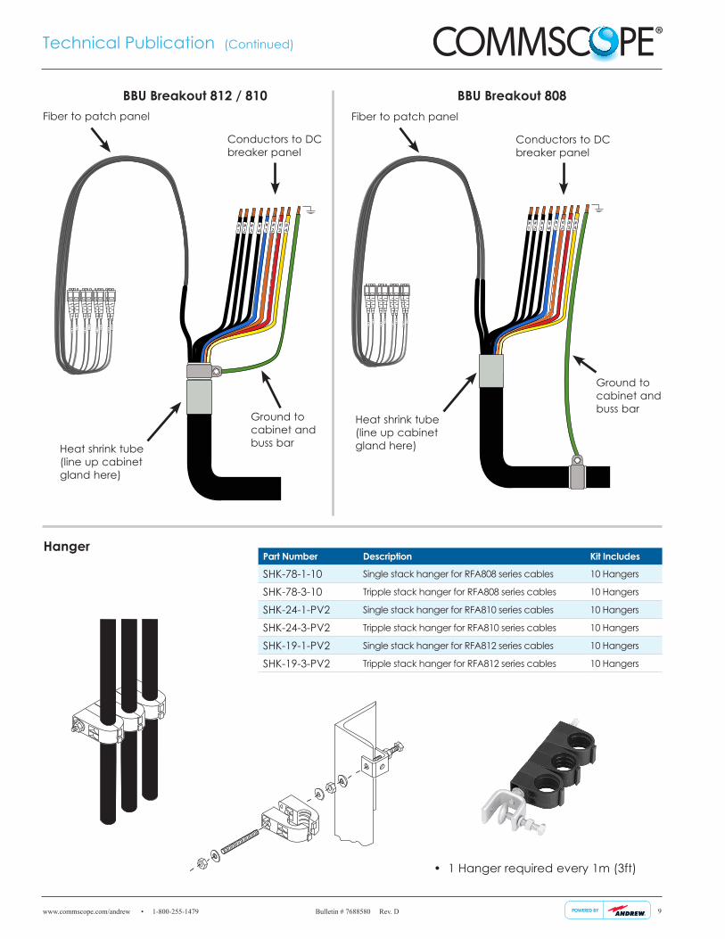
Conductors to DC breaker panel
Fiber to patch panel
Ground to cabinet and buss bar
BBU Breakout 812 / 810
9
Hanger
• 1 Hanger required every 1m (3ft)
Heat shrink tube (line up cabinet gland here)
#1
#2
#3
#4
#1
#2
#3
#4
#1#
2
#3#
4
#5#
6
#7#
8
Conductors to DC breaker panel
Fiber to patch panel
Ground to cabinet and buss bar
Heat shrink tube (line up cabinet gland here)
BBU Breakout 808
Part Number Description Kit Includes
SHK-78-1-10 Single stack hanger for RFA808 series cables 10 Hangers
SHK-78-3-10 Tripple stack hanger for RFA808 series cables 10 Hangers
SHK-24-1-PV2 Single stack hanger for RFA810 series cables 10 Hangers
SHK-24-3-PV2 Tripple stack hanger for RFA810 series cables 10 Hangers
SHK-19-1-PV2 Single stack hanger for RFA812 series cables 10 Hangers
SHK-19-3-PV2 Tripple stack hanger for RFA812 series cables 10 Hangers
www.commscope.com/andrew • 1-800-255-1479 Bulletin # 7688580 Rev. D
Technical Publication (Continued)
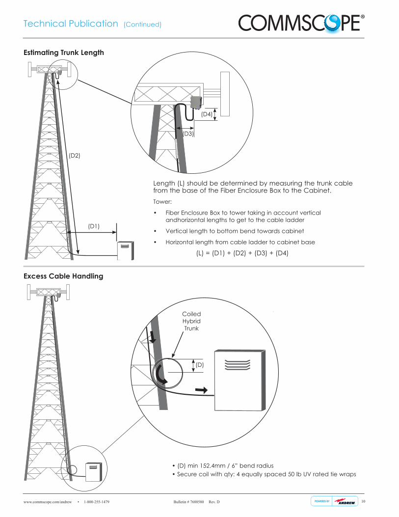
Excess Cable Handling
10
Coiled Hybrid Trunk
(D)
Estimating Trunk Length
Length (L) should be determined by measuring the trunk cable from the base of the Fiber Enclosure Box to the Cabinet.Tower:
• Fiber Enclosure Box to tower taking in account vertical and horizontal lengths to get to the cable ladder
• Vertical length to bottom bend towards cabinet
• Horizontal length from cable ladder to cabinet base
(L) = (D1) + (D2) + (D3) + (D4)
• (D) min 152.4mm / 6” bend radius • Secure coil with qty: 4 equally spaced 50 lb UV rated tie wraps
(D4)
(D3)
(D1)
(D2)
www.commscope.com/andrew • 1-800-255-1479 Bulletin # 7688580 Rev. D
Technical Publication (Continued)
11
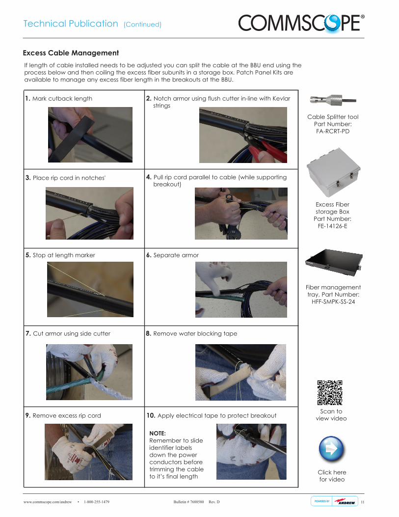
Excess Cable Management
1. Mark cutback length 2. Notch armor using flush cutter in-line with Kevlar strings
3. Place rip cord in notches' 4. Pull rip cord parallel to cable (while supporting breakout)
5. Stop at length marker 6. Separate armor
7. Cut armor using side cutter 8. Remove water blocking tape
9. Remove excess rip cord 10. Apply electrical tape to protect breakout
Fiber management tray, Part Number:
HFF-SMPK-SS-24
NOTE: Remember to slide identifier labels down the power conductors before trimming the cable to it’s final length
If length of cable installed needs to be adjusted you can split the cable at the BBU end using the process below and then coiling the excess fiber subunits in a storage box. Patch Panel Kits are available to manage any excess fiber length in the breakouts at the BBU.
Click here for video
Excess Fiber storage Box
Part Number: FE-14126-E
Scan to view video
Cable Splitter tool Part Number: FA-RCRT-PD
www.commscope.com/andrew • 1-800-255-1479 Bulletin # 7688580 Rev. D
Technical Publication (Continued)
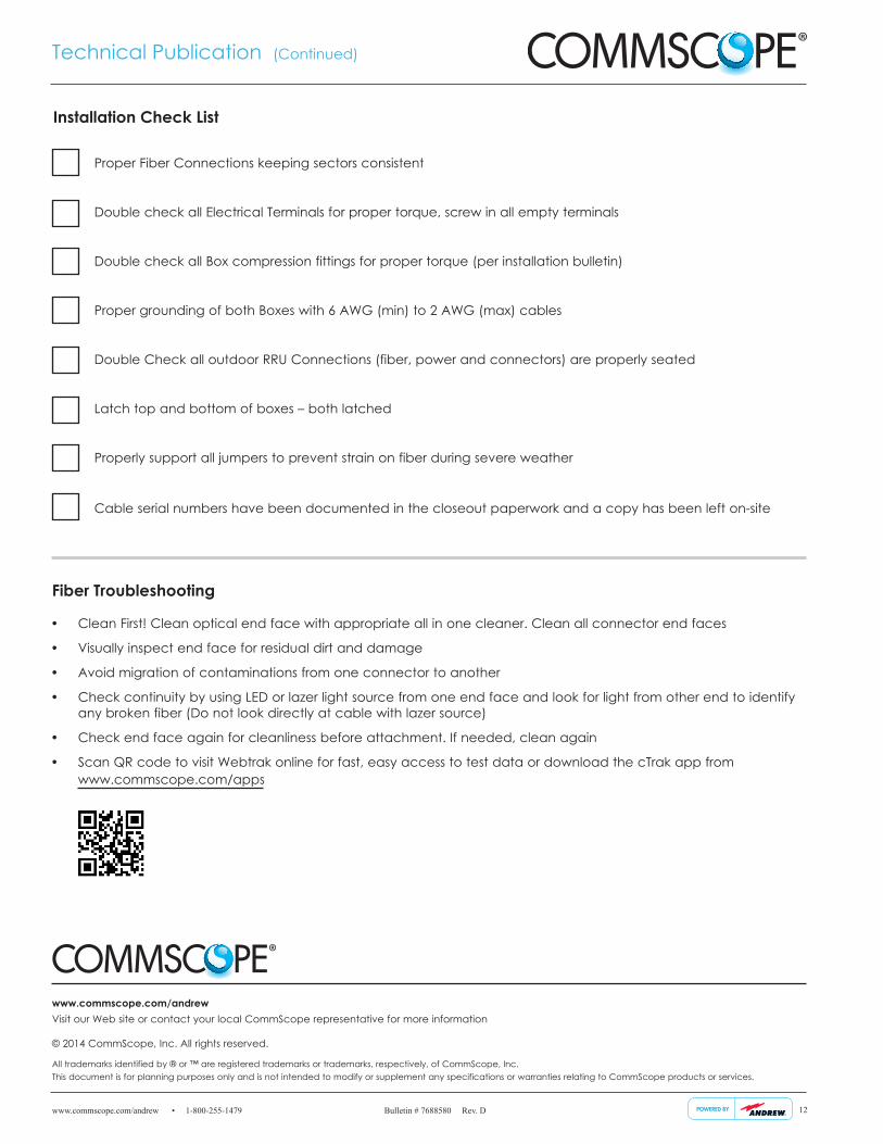
Proper Fiber Connections keeping sectors consistent
Double check all Electrical Terminals for proper torque, screw in all empty terminals
Double check all Box compression fittings for proper torque (per installation bulletin)
Proper grounding of both Boxes with 6 AWG (min) to 2 AWG (max) cables
Double Check all outdoor RRU Connections (fiber, power and connectors) are properly seated
Latch top and bottom of boxes – both latched
Properly support all jumpers to prevent strain on fiber during severe weather
Cable serial numbers have been documented in the closeout paperwork and a copy has been left on-site
Installation Check List
• Clean First! Clean optical end face with appropriate all in one cleaner. Clean all connector end faces
• Visually inspect end face for residual dirt and damage
• Avoid migration of contaminations from one connector to another
• Check continuity by using LED or lazer light source from one end face and look for light from other end to identify any broken fiber (Do not look directly at cable with lazer source)
• Check end face again for cleanliness before attachment. If needed, clean again
• Scan QR code to visit Webtrak online for fast, easy access to test data or download the cTrak app from www.commscope.com/apps
Fiber Troubleshooting
12
www.commscope.com/andrew Visit our Web site or contact your local CommScope representative for more information
© 2014 CommScope, Inc. All rights reserved.
All trademarks identified by ® or ™ are registered trademarks or trademarks, respectively, of CommScope, Inc.This document is for planning purposes only and is not intended to modify or supplement any specifications or warranties relating to CommScope products or services.