Technical Memo-Seawalk Basis of Coastal Design 2-24-2014...Basis of Coastal Engineering Design 1....
16
Technical Memorandum Page 1 Gold Creek Seawalk Project – Basis of Coastal Engineering Design February 24, 2014 Technical Memorandum Gold Creek Seawalk Project – Basis of Coastal Engineering Design 1. Project Background and Objective This technical memorandum documents the data, assumptions, modeling, and calculations related to the coastal engineering aspect of design of the island to be created as part of the Seawalk, a project undertaken by Parks and Recreation Department of the City and Borough of Juneau (CBJ). A project goal is to create a nearshore island near the mouth of Gold Creek in Gastineau Channel, west of downstown Juneau that will provide specific substrates and support a pedestrian path and habitat enhancement through the intertidal environment to upland connection points. Coastal engineering analysis and design are to develop surface material sizes for specific zones on the island having varying exposure to waves, and to determine the layer thickness of the surface materials. The location of the planned island feature is shown in Figure 1. Previous studies in the area include a coastal flooding study performed by NHC (2009) for mapping flood hazard areas for the Federal Emergency Management Agency (FEMA). Figure 1. Site location of Gold Creek Seawalk project
Transcript of Technical Memo-Seawalk Basis of Coastal Design 2-24-2014...Basis of Coastal Engineering Design 1....

Technical Memorandum Page 1 Gold Creek Seawalk Project – Basis of Coastal Engineering Design February 24, 2014
Technical Memorandum Gold Creek Seawalk Project – Basis of Coastal Engineering Design
1. Project Background and Objective
This technical memorandum documents the data, assumptions, modeling, and calculations related to the coastal engineering aspect of design of the island to be created as part of the Seawalk, a project undertaken by Parks and Recreation Department of the City and Borough of Juneau (CBJ). A project goal is to create a nearshore island near the mouth of Gold Creek in Gastineau Channel, west of downstown Juneau that will provide specific substrates and support a pedestrian path and habitat enhancement through the intertidal environment to upland connection points. Coastal engineering analysis and design are to develop surface material sizes for specific zones on the island having varying exposure to waves, and to determine the layer thickness of the surface materials. The location of the planned island feature is shown in Figure 1. Previous studies in the area include a coastal flooding study performed by NHC (2009) for mapping flood hazard areas for the Federal Emergency Management Agency (FEMA).
Figure 1. Site location of Gold Creek Seawalk project
Technical Memorandum Page 2 Gold Creek Seawalk Project – Basis of Coastal Engineering Design February 24, 2014
2. Physical Environmental Data
2.1. Topography and Bathymetry
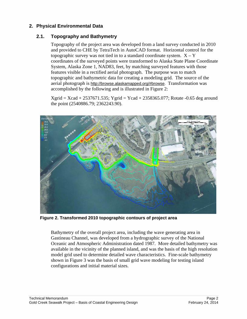
Topography of the project area was developed from a land survey conducted in 2010 and provided to CHE by TetraTech in AutoCAD format. Horizontal control for the topographic survey was not tied in to a standard coordinate system. X – Y coordinates of the surveyed points were transformed to Alaska State Plane Coordinate System, Alaska Zone 1, NAD83, feet, by matching surveyed features with those features visible in a rectified aerial photograph. The purpose was to match topographic and bathymetric data for creating a modeling grid. The source of the aerial photograph is http://browse.alaskamapped.org/#browse. Transformation was accomplished by the following and is illustrated in Figure 2:
Xgrid = Xcad + 2537671.535; Ygrid = Ycad + 2358365.077; Rotate -0.65 deg around the point (2540886.79; 2362243.90).
Figure 2. Transformed 2010 topographic contours of project area
Bathymetry of the overall project area, including the wave generating area in Gastineau Channel, was developed from a hydrographic survey of the National Oceanic and Atmospheric Administration dated 1987. More detailed bathymetry was available in the vicinity of the planned island, and was the basis of the high resolution model grid used to determine detailed wave characteristics. Fine-scale bathymetry shown in Figure 3 was the basis of small grid wave modeling for testing island configurations and initial material sizes.

Technical Memorandum Page 3 Gold Creek Seawalk Project – Basis of Coastal Engineering Design February 24, 2014
Figure 3. Elevation contours of merged topography and bathymetry
2.2. Soil Types
Soils investigation was not a part of the coastal engineering scope. Geotechnical elements for the project are presented by Golder Associates (2013). Materials upon which the island will be built are derived from coarse sediment discharged from Gold Creek and finer sediment transported to the site by tidal currents. The soil surface on which the island will be built was classified as loamy sand (CH2M HILL 2013).
2.3. Built Environment
Uplands at the existing shoreline are developed. Rock and rubble revetment currently armors the shore from the Douglas Island bridge to the mouth of Gold Creek (see Figure 1). The typical rock size and revetment slope are illustrated in Figure 4, and indicate the moderate level of wave attack to which the project area is exposed. Some of the revetted shoreline is the embankment of Egan Drive. Other parts of the revetment protect the upland on which agencies and businesses have located their facilities. Gold Creek is channelized and the location of the mouth has been stabilized with rock at the bankline.
2.4. Vertical Datum and Water Levels
The project datum is mean lower low water (MLLW). Tidal datums are summarized in Table 1.

Technical Memorandum Page 4 Gold Creek Seawalk Project – Basis of Coastal Engineering Design February 24, 2014
Figure 4. Existing erosion protection at shoreline in project area
Table 1. Tidal Datums for Juneau, AK based on NOAA Tide gauge 9452210
Datum (ft-MLLW)
MAXIMUM OBSERVED WATER LEVEL 24.9
MEAN HIGHER HIGH WATER (MHHW) 16.30
MEAN HIGH WATER (MHW) 15.34
MEAN SEA LEVEL (MSL) 8.56
MEAN TIDE LEVEL (MTL) 8.47
MEAN LOW WATER (MLW) 1.60
MEAN LOWER LOW WATER (MLLW) 0.0
MINIMUM OBSERVED WATER LEVEL -5.5
2.5. Wind Climate
Waves that are critical to design of material for the island are generated by wind blowing northwest up Gastineau Channel. The project site is sheltered from other directions, or the fetch is minor. Non-directional wind speed recordings at the Federal Building were available for analysis. Annual maximum speeds were assumed to blow from the southeast. Annual maximum speeds were fit to an extreme value distribution (Weibull distribution) to obtain speeds corresponding to given return periods (inverse of exceedance probabilities). Resulting speeds were adjusted for
Technical Memorandum Page 5 Gold Creek Seawalk Project – Basis of Coastal Engineering Design February 24, 2014
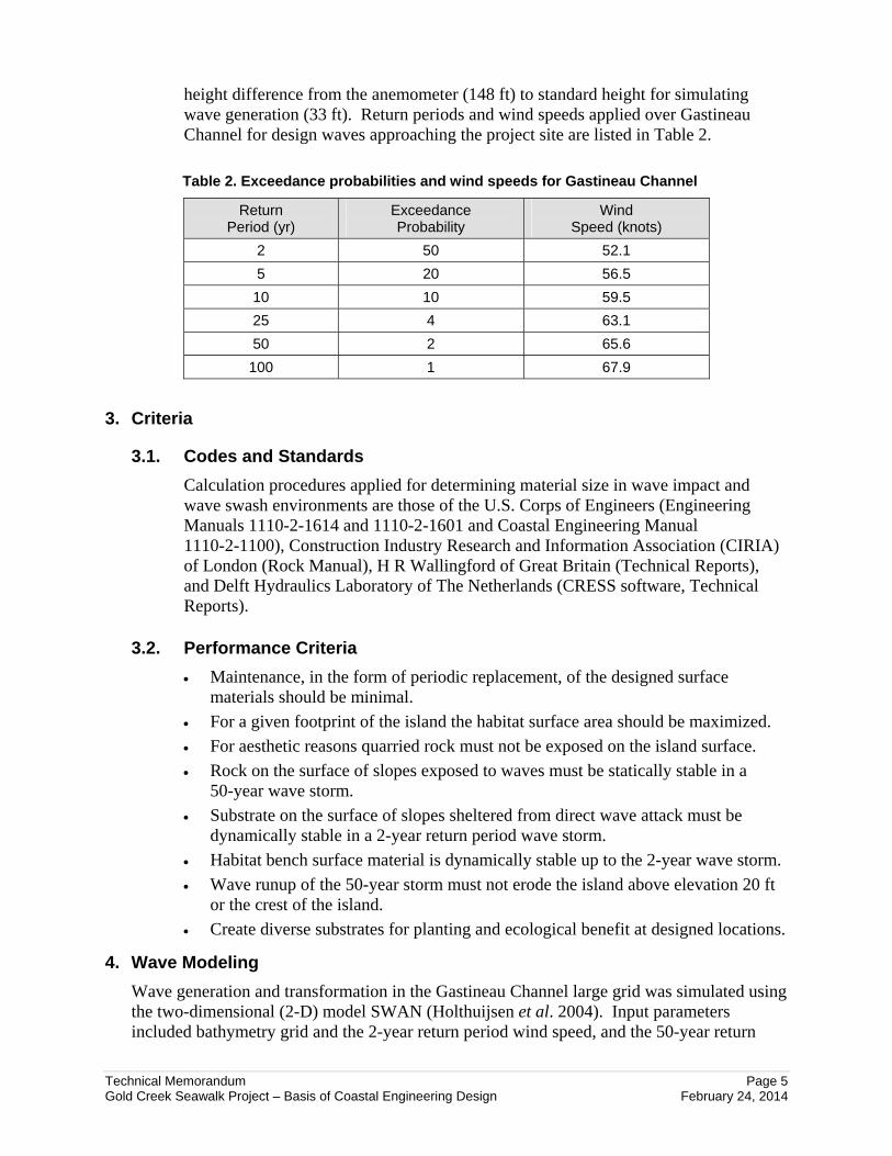
height difference from the anemometer (148 ft) to standard height for simulating wave generation (33 ft). Return periods and wind speeds applied over Gastineau Channel for design waves approaching the project site are listed in Table 2.
Table 2. Exceedance probabilities and wind speeds for Gastineau Channel
Return Period (yr)
Exceedance Probability
Wind Speed (knots)
2 50 52.1
5 20 56.5
10 10 59.5
25 4 63.1
50 2 65.6
100 1 67.9
3. Criteria
3.1. Codes and Standards
Calculation procedures applied for determining material size in wave impact and wave swash environments are those of the U.S. Corps of Engineers (Engineering Manuals 1110-2-1614 and 1110-2-1601 and Coastal Engineering Manual 1110-2-1100), Construction Industry Research and Information Association (CIRIA) of London (Rock Manual), H R Wallingford of Great Britain (Technical Reports), and Delft Hydraulics Laboratory of The Netherlands (CRESS software, Technical Reports).
3.2. Performance Criteria
Maintenance, in the form of periodic replacement, of the designed surface materials should be minimal.
For a given footprint of the island the habitat surface area should be maximized.
For aesthetic reasons quarried rock must not be exposed on the island surface.
Rock on the surface of slopes exposed to waves must be statically stable in a 50-year wave storm.
Substrate on the surface of slopes sheltered from direct wave attack must be dynamically stable in a 2-year return period wave storm.
Habitat bench surface material is dynamically stable up to the 2-year wave storm.
Wave runup of the 50-year storm must not erode the island above elevation 20 ft or the crest of the island.
Create diverse substrates for planting and ecological benefit at designed locations.
4. Wave Modeling
Wave generation and transformation in the Gastineau Channel large grid was simulated using the two-dimensional (2-D) model SWAN (Holthuijsen et al. 2004). Input parameters included bathymetry grid and the 2-year return period wind speed, and the 50-year return

Technical Memorandum Page 6 Gold Creek Seawalk Project – Basis of Coastal Engineering Design February 24, 2014
period wind speed blowing toward the direction 314.7 deg. Wave height pattern modeled in the large grid modeling domain is shown in Figure 5. A smaller mesh grid was nested in the large grid and encompassed the project site. Material size, island design, and wave forces were determined in an iterative process. Initial wave modeling resulted in preliminary wave height, period, and direction information at the edge of the project site. This information was the basis of an initial estimate of material size on the exposed side if the island for the tide levels (described in Section 5) that were input to the wave model. Combinations of material sizes and slope angles were considered in refining the island configuration and footprint size.
Elevation contours of the refined island were coded into the bathymetry grid of the high-resolution wave model. This detailed model domain is shown in Figure 6. The locations of points for extracting wave information are shown in Figure 7. Wave information for modeled cases of wind speed and tide elevation is summarized for each extraction point in Table 3. Modeled wave height and period were used in determining material size specific to the location on the island in the following section.
Figure 5. Large grid wave model domain and computed wave height

Technical Memorandum Page 7 Gold Creek Seawalk Project – Basis of Coastal Engineering Design February 24, 2014
Figure 6. High resolution wave model and extraction points for wave information
Figure 7. Point locations for extracting modeled wave information for design

Technical Memorandum Page 8 Gold Creek Seawalk Project – Basis of Coastal Engineering Design February 24, 2014
Table 3. Nearshore wave height in feet at extraction points on island
Pt # 2-yr
MHHW
5-yr
MHHW
50-yr MHHW
50-yr +20’ MLLW
1 4.1 4.4 5.3 5.1
2 5.3 5.5 5.8 6.7
3 3.9 3.9 3.9 5.8
4 1.1 1.1 1.1 2
5 0.8 0.8 0.8 1.3
6 0.8 0.8 0.8 0.8
7 1 1 1.1 1.2
8 2.3 2.3 2.5 2.8
9 3.8 4.1 4.8 4.2
10 3.7 3.8 4.2 5.7
11 3.7 3.8 4.3 5
12 3.2 3.4 3.7 5.2
13 3.3 3.3 3.5 5.6
5. Surface Material Stability
After examining the spatial pattern of wave height listed in Table 3, the island was divided into five regions below elevation 20 ft. Above elevation 20 ft Region 6 is on the exposed side of the island, and Region 7 is on the sheltered side. Figure 8 illustrates the region locations for calculating material sizes that meet engineering performance criteria of the separate regions. Hydrodynamics and material stability calculation procedures and results are described below for the individual regions. It is recognized that other materials will be added to the regions or mixed with the materials derived below for purposes of enhancing specific habitats. Materials meeting the engineering criteria are only the stable framework within which the broader project elements will function. Specifications for the composite material, including planting medium, for the regions will be developed during final design.
5.1. Region 1 Naturally Rounded Boulders
The Region 1 wave climate is characterized by output points 1, 2, 3, 8, and 9. The area is exposed to the largest waves that impinge on the island. Incident significant wave height and spectral peak period selected for analyzing material stability in Region 1 is 6.7 ft and 6.0 sec, respectively. The elevation range of Region 1 is 10 to 13 ft, and the slope angle is 3 H : 1 V. The maximum water depth at 20-ft tide level is 10 ft. Criteria are static stability when subjected to the most critical combination of wave height and water level. The 50-year storm wave was selected for design because the critical function of the boulders is support of the outer layer of material upslope from it. The surface of this region is to have the appearance of rounded boulders, with interstices filled with growth medium to support plantings.

Technical Memorandum Page 9 Gold Creek Seawalk Project – Basis of Coastal Engineering Design February 24, 2014
Figure 8. Regions for separate surface material types on island
Equations of Melby (CIRIA, 2007, Chapter 6) were applied to analyze static stability of rounded boulders under wave attack. Waves apply forces to destabilize boulders by breaking wave forces at certain water levels and by orbital velocity forces at other levels. Depth limited wave height at the upper elevation of Region 1 was analyzed using streamfunction wave theory (Dean 1965) to determine controlling parameters for stability of the boulders on the slope. The 50-year wave propagating to the island with the tide level of MHHW and breaking on the slope is the design condition for Region 1. Median stone diameter for static stability is 2.0 ft. Armor layer thickness is ordinarily equal to two stone diameters. A layer of rounded boulders one diameter thick is practical from the standpoint of economy of materials under the condition that the material below the surface layer is angular stone having a median diameter at least 1.8 ft. Individual placement of the rounded boulders will be required to attain maximum stone-to-stone contact, for achieving necessary stability. The potential for surface irregularity of the slope comprised of one layer of rounded boulders is minimized by restricting the small fraction of the size gradation, making a “narrow” gradation. Interstitial spaces will be filled with cobble-gravel and smaller medium to encourage growth of marine vegetation. Constructed thickness of the rounded

Technical Memorandum Page 10 Gold Creek Seawalk Project – Basis of Coastal Engineering Design February 24, 2014
boulder layer in Region 1 is 30 inches, including the smaller size fill material. Size gradation for rounded boulders is presented in Section 6.
5.2. Region 2 Cobble-Gravel-Topsoil Blend for Soil Pockets and Marsh
The Region 2 wave climate is characterized by output point 10. The area is exposed to nearly the largest waves that impinge on the island. Incident significant wave height and spectral peak period selected for analyzing material appropriate for Region 2 habitat bench is 3.7 ft and 6.0 sec, respectively. The elevation of Region 2 is 13 ft. The surface slope is nearly flat. Water depth at 20-ft tide level is 7 ft. Criteria are dynamic stability when subjected to the most critical combination of wave height and water level. The 2-year wave storm wave was selected for design because the surface material is to function as habitat and not erosion protection. The substrate is specified to be moveable in 50 percent annual exceedance probability (2-year return period) wave conditions, but remain on the bench (dynamic stability). It is not expected to remain in the profile when impacted by storms greater than the 4 percent annual exceedance probability (25-year storm).
Bottom level wave orbital velocity developed at the most critical tide elevation was analyzed using streamfunction wave theory (Dean 1965) to determine controlling parameters for dynamic stability of the bench material. The 2-year wave propagating to the island with the tide level of MHHW and propagating across the bench creates a maximum bottom velocity of 5.0 ft/sec. A threshold of motion relationship developed by Maynord (1998) for sediment exposed to near-bottom velocity was applied to determine particle size moved by wave swash velocity greater than 5 ft/sec. Median size for dynamic stability is 1.5 inches. Size gradation for material meeting stability requirements is presented in Section 6. Soil will be blended with the cobble-gravel material for biological and landscape purposes. Soil will not remain in the surface layer during design wave attack, but will not reduce stability of the analyzed granular material.
5.3. Region 3 Naturally Rounded Cobbles
The Region 3 wave climate is characterized by output points 4 and 5. The area is exposed to only low wave heights. Incident wave height and period selected for analyzing material stability in Region 3 refract around the island and are 2.0 ft and 6.0 sec, respectively. The elevation range of Region 3 is 9 to 20 ft, and the slope angle is 5 H : 1 V. Maximum water depth at 20-ft tide level is 11 ft. Criteria are static stability when subjected to the most critical combination of wave height and water level. The 50-year wave storm wave was selected for design because the critical function of the lower course of cobbles is support of the outer layer of material upslope from it. The same material will be applied to the surface of all of Region 3, and is to have the appearance of rounded cobbles with interstices filled with growth medium to support plantings.
Equations of Van der Meer and Melby (CIRIA, 2007, Chapter 6) were applied to analyze static stability of rounded cobbles under wave attack. Depth limited wave height at the upper elevation of Region 3 was analyzed using streamfunction wave theory (Dean 1965) to determine controlling parameters for stability of the cobbles on

Technical Memorandum Page 11 Gold Creek Seawalk Project – Basis of Coastal Engineering Design February 24, 2014
the slope. The 50-year wave propagating to the area of Region 3 with the tide level of MHHW and breaking on the slope is the design condition for Region 3. The median cobble diameter for static stability is 0.7 ft. A layer of rounded cobbles two diameters thick is practical from the standpoint of economy of materials and constructability. Grading the layer of cobbles will achieve sufficient stone-to-stone contact for stability requirements. Interstitial spaces will be filled with finer material to encourage growth of plantings. Rounded cobble layer thickness in Region 3 is at least 1.4 ft. Size gradation to meet requirements of engineering stability is presented in Section 6.
5.4. Region 4 Cobble-Gravel and Soil Mix
The Region 4 wave climate is characterized by output points 6 and 7. The area is on the lee side of the island and is exposed to only low wave heights. Wave height and period selected for analyzing material stability in Region 4 is 1.2 ft and 6.0 sec, respectively. The elevation range of Region 4 is 9 to 20 ft and the slope angle is 7 H : 1 V. The maximum water depth at 20-ft tide level is 11 ft. Criteria are dynamic stability when subjected to the most critical combination of wave height and water level. The 2-year wave storm wave was selected for design because the surface material is to function as habitat and not erosion protection. The substrate is specified to be moveable in 50 percent annual exceedance probability wave conditions, but remain on the slope (dynamic stability). It is not expected to remain in the profile when impacted by storms greater than the 4 percent annual exceedance probability (25-year storm).
Equations of Powell (1993) were applied to analyze dynamic stability of gravelly material on a sloping beach under wave attack. Profile forming forces at Region 4 were analyzed to determine material size and gradation that would be in equilibrium with the specified slope and wave height and period. Median particle diameter for dynamic stability is 0.25 inch based on engineering criteria. Soil will be blended with the cobble-gravel material for biological and landscape purposes. Soil will not remain in the surface layer during design wave attack, but will not reduce stability of the analyzed granular material. Layer thickness is recommended to be one foot to minimize maintenance of the slope. Size gradation to meet requirements of engineering stability is presented in Section 6.
5.5. Region 5 Naturally Rounded Boulders
The Region 5 wave climate is characterized by output points 11, 12, and 13. The area is exposed to among the largest waves that impinge on the island. Incident wave height and period selected for analyzing material stability in Region 5 is 5.6 ft and 6.0 sec, respectively. The elevation range of Region 5 is 13 to 20 ft and the slope angle is 5 H : 1 V. The maximum water depth at 20-ft tide level is 7 ft. Criteria are static stability when subjected to the most critical combination of wave height and water level. The 50-year storm wave was selected for design because of the requirement that the rounded boulders remain in place on the exposed side of the island to provide an aesthetic appearance and stable matrix for plantings. The surface of this region is to have interstices filled with growth medium to support plantings.

Technical Memorandum Page 12 Gold Creek Seawalk Project – Basis of Coastal Engineering Design February 24, 2014
Equations of Melby (CIRIA, 2007, Chapter 6) were applied to analyze static stability of rounded boulders under wave attack. Incident waves of Region 5 were applied to determine controlling parameters for stability of the boulders on the slope. The 50-year wave propagating to the area of Region 5 with the tide level of 20 ft and breaking on the slope is the design condition for Region 5. The median stone diameter for static stability is 1.6 ft. A layer of rounded boulders one diameter thick is practical from the standpoint of economy of materials under the condition that the under layer is angular stone having a median diameter at least 1.5 ft. Individual placement of the rounded boulders will be required to attain maximum stone-to-stone contact. The potential for surface irregularity of the slope comprised of one layer of rounded boulders is minimized by restricting the small fraction of the size gradation. Interstitial spaces will be filled with cobble-gravel and smaller medium to encourage growth of marine vegetation. The thickness of the rounded boulder layer and planting medium in Region 5 is 30 inches. Size gradation to meet requirements of engineering stability is presented in Section 6.
5.6. Region 6 Habitat Subjected to Wave Runup
Region 6 is subjected to wave swash and runup above elevation 20 ft generated from wave breaking in Region 5. The elevation range of Region 6 is 20 to 25 ft and the slope angle is 5 H : 1 V. Wave swash resulting from a breaking wave with incident height of 5.6 ft and period 6.0 seconds with a tide level of 20 ft is the selected condition for analyzing material stability in Region 6. Criteria are static stability when subjected to the wave swash velocity developed by the selected design conditions. The 50-year storm wave was selected for design because of the requirement that the stable matrix of the surface material remain in place on the exposed side of the island in extreme wave events, even if planting medium incorporated in the surface requires replacement.
The selected wave breaking in Region 5 and running up the slope of Region 6 generates a maximum velocity of 9.4 ft/sec at elevation 20 and diminishes to 6.7 ft/sec at the point of overtopping the island at elevation 25 ft. A threshold of motion relationship developed by Maynord (1998) for sediment exposed to near-bottom velocity was applied to determine particle size. The median particle size for static stability is 6 inches at the elevation of greatest swash velocity. The same material gradation should be applied to all of Region 6. Finer material and soil may be added to fill voids in the coarse material to support plantings in this region. Size gradation to meet requirements of engineering stability is presented in Section 6.
5.7. Region 7 Habitat Subjected to Wave Overwash
The crest elevation of the island will be 25 ft. During the design wave storm, assumed to occur with a high tide, wave runup will exceed the crest elevation and waves will wash over the lee side of the island. Erosion potential of the overwash is approximately equal to that at the crest of Region 6. Criteria are static stability when subjected to the wave overtopping velocity developed by the selected design conditions. The 50-year storm wave was selected for design because of the requirement that the stable matrix of the surface material remain in place on the lee

Technical Memorandum Page 13 Gold Creek Seawalk Project – Basis of Coastal Engineering Design February 24, 2014
side of the island in extreme wave events, even if planting medium incorporated in the surface requires replacement.
The selected wave overtopping of Region 6 and running down the slope of Region 7 generates a maximum velocity of 6.7 ft/sec at elevation 25 and diminishes as overtopping water percolates into the surface. A threshold of motion relationship developed by Maynord (1998) for sediment exposed to near-bottom velocity was applied to determine particle size. The median particle size for static stability is 3 inches at the elevation of greatest overtopping velocity. The same material gradation should be applied to all of Region 7. A mulch composed of cobbles specified for stability in design conditions and soil to support plantings in less extreme conditions may form the surface layer (minimum 6 inches thick) to achieve habitat goals. Size gradation to meet requirements of engineering stability is presented in Section 6.
6. Surface Material Description
Stability calculations for material in the separate regions determined median size of stone or coarse material that is suitable for the particular wave exposure and engineering performance requirements. Natural materials have a range of sizes, and each material source has a characteristic size distribution. Material is described below using an assumed size gradation for the purpose of preliminary design, permitting, and initial cost estimating. The information below is expected to be modified during final design to better conform to local availability of suitable material and allow more favorable bid prices.
Material characteristics were determined through this coastal engineering analysis for stability in each region’s specific wave and current regimes. The rounded shape of the boulders conforms to aesthetic and environmental requirements, and is accounted for in the stability analysis. Other substrate will be added to materials determined for regions 1, 2, 3, 5, 6, and 7 to achieve habitat goals. Only the coastal engineering design requirements are summarized below for the seven separate areas. Requirements for durability and suitable shape for stone and tolerance for layer thickness will be developed in final design.
Practical considerations of material production and constructability indicate that the same coarse materials (4-inch-minus) may be supplied for Regions 2 and 7. Specifications for such locally available material have been developed for a previous CBJ project and excerpts were provided by TetraTech. Regions 3 and 6 may be supplied with similar boulder material (4-inch to 12-inch), using previously developed specifications, which could simplify construction, inspection, and contract management.
6.1. Region 1 Naturally Rounded Boulders
Calculated gradation for stability is tabulated below. Layer thickness shall be 30 inches.
Approx. Size (in.)
Percent Smaller by Weight
38 100
28 50-90
20 15-50
15 0

Technical Memorandum Page 14 Gold Creek Seawalk Project – Basis of Coastal Engineering Design February 24, 2014
6.2. Region 2 Cobble-Gravel-Topsoil Blend for Soil Pockets and Marsh
Calculated gradation for stability is tabulated below. Layer thickness shall be 12 inches.
Approx. Size (in.)
Percent Smaller by Weight
3 100
2 50-90
1 15-50
0.5 15 max
6.3. Region 3 Naturally Rounded Cobbles
Calculated gradation for stability is tabulated below. Layer thickness shall be 16 inches.
Approx. Size (in.)
Percent Smaller by Weight
12 100
10 50-90
7 15-60
5 15 max
6.4. Region 4 Cobble-Gravel and Soil Mix
Calculated gradation for stability is tabulated below. Layer thickness shall be 12 inches.
Approx. Size (in.)
Percent Smaller by Weight
0.6 100
0.35 50-90
0.18 15-50
0.08 15 max
6.5. Region 5 Naturally Rounded Boulders
Calculated gradation for stability is tabulated below. Layer thickness shall be 30 inches.
Approx. Size (in.)
Percent Smaller by Weight
30 100
23 50-90
19 15-70
12 0

Technical Memorandum Page 15 Gold Creek Seawalk Project – Basis of Coastal Engineering Design February 24, 2014
6.6. Region 6 Habitat Subjected to Wave Runup
Calculated gradation for stability is tabulated below. Layer thickness shall be 36 inches.
Approx. Size (in.)
Percent Smaller by Weight
9 100
6.5 50-90
5 15-50
3.5 15 max
6.7. Region 7 Habitat Subjected to Wave Overwash
Calculated gradation for stability is tabulated below. Layer thickness shall be 36 inches.
Approx. Size (in.)
Percent Smaller by Weight
5 100
3.5 50-90
2.5 15-50
1.7 15 max
7. References
CH2M HILL. 2013. Appendix F Sediment Sample Results. Prepared by CH2M HILL, Portland, OR.
CIRIA. 2007. The Rock Manual, The Use of Rock in Hydraulic Engineering (2nd edition) C683, CIRIA (Reprinted 2012), London.
Dean, Robert G. 1965. Stream Function Wave Theory: Validity and Application. Proceedings of Coastal Engineering, Specialty Conference of American Society of Civil Engineers, Santa Barbara, CA, p. 269-300. A.S.C.E., New York.
Golder Associates. 2013. Juneau Seawalk Upgrades Geotechnical Findings and Recommendations. Report submitted to TetraTech, Inc. Prepared by Golder Associates, December 26, 2013, Anchorage, AK.
Holthuijsen, L.H., Booij, N., Ris, R.C., Haagsma, I.J.G., Kieftenburg, A.T.M.M., Kriezi, E.E., Zijlema, M. & A.J. van der Westhuysen. 2004. SWAN Cycle III Version 40.31 User Manual.
Maynord, Steve. 1998. Guidance for In-Situ subaqueous Capping of Contaminated Sediments Appendix A: Armor Layer Design. U.S. Environmental Protection Agency.
NHC. 2009. FEMA Coastal Flood Insurance Study, City and Borough of Juneau. Report prepared for Region 10 FEMA. Prepared by Northwest Hydraulic Consultants, September 18, 2009, Tukwila, WA.