Technical Manual - Pronto...
36
Technical Manual Multi-residential Internal Walls July 2015. Version 1.0
Transcript of Technical Manual - Pronto...
Technical ManualMulti-residential Internal Walls
July 2015. Version 1.0


Pronto Panel™ Technical Manual Contents
Introduction
Building with Pronto Panel 6
Benefits 7
System Information
Compliance and Quality 10
Scope and Applications 11
Product Range 13
Material Properties 14
Structural Properties 15
Pronto Panel Systems 16
System Details 19
Installation Details
Delivery on Site 26
Pronto Panel Safety 26
Installation 28
Warranty 34
Associated Companies 35
| 3Technical Manual |

| 5Technical Manual |
Pronto Panel Introduction
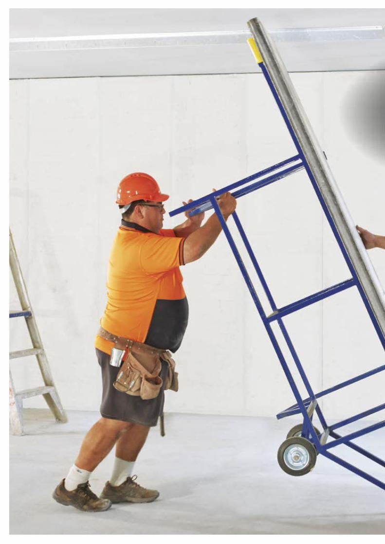
Pronto Panel is a non-load bearing panel system that can be used both internally and externally. Pronto Panel’s durable, lightweight and simplistic nature makes it perfectly suitable for both residential and commercial projects.
Pronto Panel Technical Manual
Building with Pronto Panel
High fire resistance
6 | | Technical Manual

The benefits stack up
Lightweight
Exceptionally low water permeability
High pull-out strength
Durable
Effective acoustic insulation
Minimal components
High fire resistance
Exceptional lateral load capacity
Fast and simple installation

Pronto Panel System Information
8 | | Technical Manual

| 9Technical Manual |
Xxxx xxxxxxx
| 9Technical Manual |

Pronto Panel Technical Manual
Compliance and Quality
Compliance
Pronto Panel has been extensively tested at CSIRO, University of Newcastle and other NATA accredited laboratories. The manufacturing, testing and installation procedures have been accredited for compliance with the National Construction Code (NCC) by GlobalMark Pty Ltd for CodeMark certification.
CodeMark™ Certification
CodeMark is a building product certification scheme. The CodeMark scheme supports the use of new and innovative building products by providing a nationally and internationally accepted process for products to be assessed for compliance with the requirements of the building codes of Australia and New Zealand. The scheme provides confidence and certainty to regulatory authorities and the market through the issuing of a Certificate of Conformity.
National Construction Code
Pronto Panel meets the provisions of the NCC Performance Requirements as an Alternative Solution, specified in clause A 0.5 of the NCC. In accordance with clause A 0.10 the relevant deemed to satisfy provision, it has been identified for structural adequacy, fire resistance and acoustic performance. Thorough testing has been conducted to verify these requirements using a registered testing authority and expert judgement by professional engineers.
Quality
Pronto Panel is manufactured under licence by a company with full ISO 9001 accreditation. This ensures that all materials, processes, quality control and quality assurance are rigorously checked and verified.
Pronto Panel has achieved CodeMark certification, an independent accreditation to further ensure the quality and consistency of the product.
Pronto Panel has numerous quality checks, both during manufacture and before dispatch, to ensure only the highest quality product reaches the market.
Each batch of Pronto Panel can be traced and verified by its batch number to its original raw materials.
Intention
This manual is intended to be used by experienced and qualified builders, engineers and architects. No responsibility is taken for inappropriate, incomplete and incorrect use of the information in this manual.
30050
10 | | Technical Manual

| 11Technical Manual |
Pronto Panel Technical Manual
Scope and Applications
Pronto Panel is suitable for any non-load bearing wall that requires fire and sound insulation.
Pronto Panel can be used for walls separating sole occupancy units or for walls separating sole occupancy units from a public corridor or public lobby. These walls require impact sound attenuation.
Pronto Panel installation must be carried out by qualified panel installers. No responsibility is taken for incorrect installations of Pronto Panel.

Pronto Panel Technical Manual
Scope and Applications
1. Internal Wall / Partition Wall
An internal or partition wall is a wall that separates two rooms within a sole occupancy unit as illustrated.
Sound requirements none
Fire requirements none
2. Inter-tenancy Wall An inter-tenancy wall is a wall that separates sole occupancy units as illustrated.
Note: A wall separating a habitable room to a wet room needs to be discontinuous.
Sound requirements Rw+Ctr ≥ 50
Fire requirements (Non load-bearing)
-/60/60
Bedroom 1 – Dwelling 1
Bedroom – Dwelling 1
Bedroom – Dwelling 1
Bedroom – Dwelling 1
Bathroom – Dwelling 2
Bedroom – Dwelling 2
Public Lobby
Bedroom 2 – Dwelling 1
3. Common wall A common wall is a wall that separates sole occupancy units from a public corridor, public lobby or the like, as illustrated.
Sound requirements Rw ≥ 50
Fire requirements (Non load-bearing)
-/60/60
Pronto Panel offers a range of wall systems for inter-tenancy walls, common walls and partition walls.
12 | | Technical Manual
Pronto Panel Technical Manual
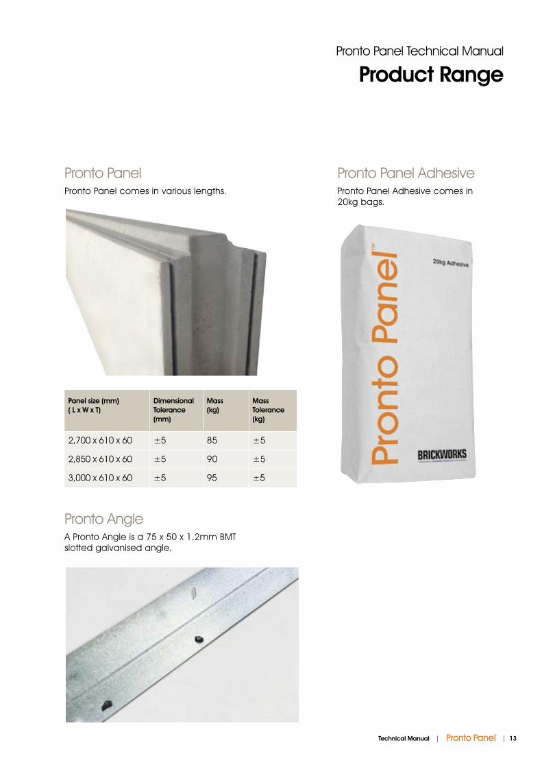
Product Range
Pronto Panel AdhesivePronto Panel Adhesive comes in 20kg bags.
Pronto PanelPronto Panel comes in various lengths.
Pronto AngleA Pronto Angle is a 75 x 50 x 1.2mm BMT slotted galvanised angle.
Panel size (mm) ( L x W x T)
Dimensional Tolerance (mm)
Mass (kg)
Mass Tolerance (kg)
2,700 x 610 x 60 ±5 85 ±5
2,850 x 610 x 60 ±5 90 ±5
3,000 x 610 x 60 ±5 95 ±5
| 13Technical Manual |

Pronto Panel Technical Manual
Material Properties
Pronto Panel consists of a composite of lightweight aggregates bonded into a cementitious matrix. The panels are sheeted with a Calcium Silicate board. The panels have a tongue and groove on the vertical edges to interlock and to prevent the passage of noise and fire.
Due to its design, the panels can also be cut to size as required, without compromising its structural capacity.
Pronto Panel Material Properties
Properties Value
Working Density 52kg/m2
Dry Density 770kg/m3
Water Absorption <5 %
*R-Value 0.253m2 K/W
* The panel is tested in accordance with the Australian and New Zealand Standard AS/NZS 4859.1
3D Panel Detail
14 | | Technical Manual

| 15Technical Manual |
Pronto Panel Technical Manual
Structural Properties
1. Ultimate Design LoadWhen correctly installed, a 3m long Pronto Panel will resist an internal pressure of 0.79kPa.
Pronto Panel has undergone extensive testing.
2. FixturesWhen correctly installed, 8g screws embedded 50mm into the Pronto Panel and spaced at 300mm centres, have a pull out tensile strength of 3.80kN/m and a shear strength of 4.79kN/m.
3. Thermal PropertiesPronto Panel’s R value is 0.253m2.K/W with no plasterboard or other linings.
3m Pronto Panel0.79kPa
Ultimate Design Pressure in One-Way Bending
Length (mm) Ultimate Design Load (kPa)
2,700 0.98
2,850 0.88
3,000 0.79
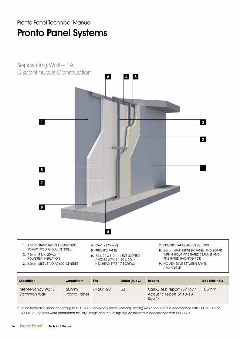
Application Component Fire Sound (Rw+Ctr) Reports Wall Thickness
Inter-tenancy Wall / Common Wall
60mm Pronto Panel
-/120/120 50 CSIRO test report FSV1677 Acoustic report 5518-1B RevC*
185mm
* Sound Reduction Index according to ISO 140-3 (laboratory measurement). Testing was conducted in accordance with ISO 140-4 and
ISO 140-3. The tests were conducted by Day Design and the ratings are calculated in accordance with ISO 717-1.
Separating Wall – 1A Discontinuous Construction
1. 13mm STANDARD PLASTERBOARD SCREW FIXED AT 600 CENTRES
2. 75mm thick, 25kg/m³ POLYESTER INSULATION
3. 64mm STEEL STUD AT 600 CENTRES
4. CAVITY (35mm)
5. PRONTO PANEL
6. 75 x 50 x 1.2mm BMT SLOTTED ANGLES WITH 14-10 x 50mm HEX HEAD TYPE 17 SCREWS
7. PRONTO PANEL ADHESIVE JOINT
8. 20mm GAP BETWEEN PANEL AND SOFFIT WITH 4 HOUR FIRE RATED SEALANT AND FIRE RATED BACKING ROD
9. NO ADHESIVE BETWEEN PANEL AND ANGLE
Pronto Panel Technical Manual
Pronto Panel Systems
1
2
31
5
7
9
4 86
6
16 | | Technical Manual

Application Component Fire Sound (Rw+Ctr) Reports Wall Thickness
Inter-tenancy Wall / Common Wall
60mm Pronto Panel
-/120/120 51 CSIRO test report FSV1677 Acoustic report 5518-1D RevC*
185mm
* Sound Reduction Index according to ISO 140-3 (laboratory measurement). Testing was conducted in accordance with ISO 140-4 and
ISO 140-3. The tests were conducted by Day Design and the ratings are calculated in accordance with ISO 717-1.
Pronto Panel Technical Manual
Pronto Panel Systems
Separating Wall – 1BDiscontinuous Construction
1. 13mm FIRE RESISTANT PLASTERBOARD SCREW FIXED AT 600 CENTRES
2. 75mm thick, 11kg/m³ INSULATION
3. 64mm STEEL STUD AT 600 CENTRES
4. CAVITY (35mm)
5. PRONTO PANEL
6. 75 x 50 x 1.2mm BMT SLOTTED ANGLES WITH 14-10 x 50mm HEX HEAD TYPE 17 SCREWS
7. PRONTO PANEL ADHESIVE JOINT
8. 20mm GAP BETWEEN PANEL AND SOFFIT WITH 4 HOUR FIRE RATED SEALANT AND FIRE RATED BACKING ROD
9. NO ADHESIVE BETWEEN PANEL AND ANGLE
1
5
7
9
6
4 86
1
2
3
| 17Technical Manual |

Application Component Fire Sound (Rw+Ctr) Reports Wall Thickness
Internal/ Partition wall
60mm Pronto Panel
-/60/60 30 CSIRO test report FSV1705 Acoustic report 5518-1A RevC*
80mm
* Sound Reduction Index according to ISO 140-3 (laboratory measurement). Testing was conducted in accordance with ISO 140-4 and ISO 140-3. The tests were conducted by Day Design and the ratings are calculated in accordance with ISO 717-1.
Separating Wall – 1CContinuous Construction
Pronto Panel Technical Manual
Pronto Panel Systems
1
6
3
53
1
2
1. PLASTERBOARD SCREW FIXED AT 600 CENTRES
2. PRONTO PANEL
3. 75 x 50 x 1.2mm BMT SLOTTED ANGLES WITH 14-10 x 50mm HEX HEAD TYPE 17 SCREWS
4. PRONTO PANEL ADHESIVE JOINT
5. 20mm GAP BETWEEN PANEL AND SOFFIT WITH 4 HOUR FIRE RATED SEALANT AND FIRE RATED BACKING ROD
6. NO ADHESIVE BETWEEN PANEL AND ANGLE
4
18 | | Technical Manual
Pronto Panel Technical Manual
System Details
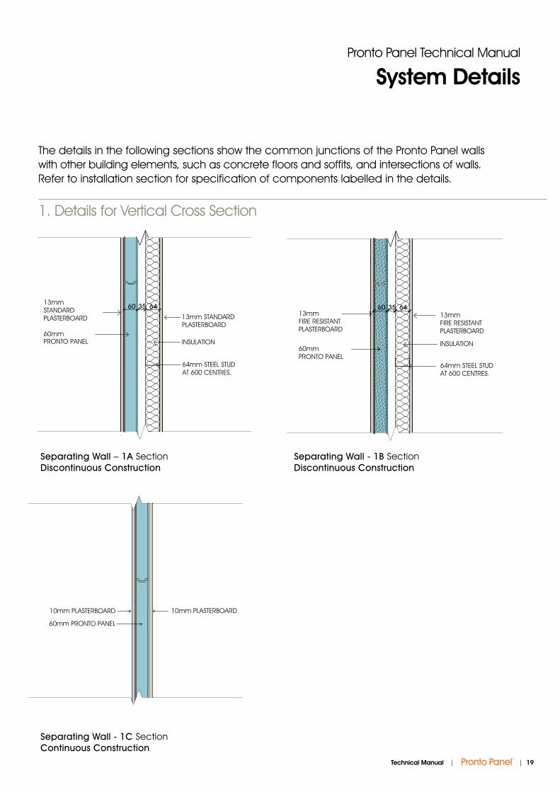
The details in the following sections show the common junctions of the Pronto Panel walls with other building elements, such as concrete floors and soffits, and intersections of walls. Refer to installation section for specification of components labelled in the details.
1. Details for Vertical Cross Section
Separating Wall – 1A Section Discontinuous Construction
Separating Wall - 1C SectionContinuous Construction
Separating Wall - 1B SectionDiscontinuous Construction
SEPARATING WALLS - 1ASECTION - SCALE 1:5
35 64
13mm STANDARDPLASTERBOARD
INSULATION
60
64mm STEEL STUDAT 600 CENTRES.
13mm STANDARD PLASTERBOARD
60mm PRONTO PANEL
SEPARATING WALLS - 1CSECTION - SCALE 1:5
35 64
INSULATION
60
64mm STEEL STUDAT 600 CENTRES.
60mm PRONTO PANEL
13mm FIRE RESISTANTPLASTERBOARD
13mm FIRE RESISTANTPLASTERBOARD
10mm PLASTERBOARD
60mm PRONTO PANEL
10mm PLASTERBOARD
SHAFT WALLS - 1JSECTION - SCALE 1:5
| 19Technical Manual |

Pronto Panel Technical Manual
System Details
3. Pronto Panel to Angle
Pronto Panel To Angle Elevation
PRONTO ANGLEFIXED TO SLAB
PRONTO PANEL
TWO SCREWSPER PANEL
TYPE17.14-10 x 50mmHEX SCREWS
2. Details for Top and Base of Wall
Wall Top Section Wall Base Section
2030
FIX ANGLE TO SLAB
75 X 50mm SLOTTED ANGLE2 FIXINGS PER PANEL
TYPE 17 14-10X 50mm HEX SCREWS60mm PRONTO PANEL
FIRE AND ACOUSTICRATED SEALANT ON
BACKING ROD
CONCRETE SOFFIT
FIX ANGLE TO SLAB
75 X 50mm SLOTTED ANGLE2 FIXINGS PER PANEL
TYPE 17 14-10X 50mmHEX SCREWS
60mm PRONTO PANEL
20 | | Technical Manual

Pronto Panel Technical Manual
System Details
5. Corner Joint
Corner Joint Section
FIXING @ 600mm CRS MAX
60mm PRONTO PANEL
FIRE & ACOUSTIC SEALANTON BACKING ROD (IF REQ'D)
FIRE & ACOUSTIC SEALANTON BACKING ROD (IF REQ'D)
CORNER JOINT - 6SECTION - SCALE 1:5
6. Corner Details
60mm PRONTO PANEL
60mm PRONTO PANEL
FIRE AND ACOUSTIC RATED SEALANT
FIRE AND ACOUSTIC RATED SEALANT
PLASTERBOARD AS PER SYSTEM REQUIREMENTS
PLASTERBOARD AS PER SYSTEM REQUIREMENTS
PRONTO PANEL ADHESIVE BETWEEN PANELS
PRONTO PANEL ADHESIVE BETWEEN PANELS
14-10 X 150mm HEX HEAD COARSE THREAD SCREW AT 900mm MAX CENTRES AND 100mm MAX FROM PANEL ENDS(3 PER PANEL MIN)14-10 X 150mm HEX HEAD
COARSE THREAD SCREW AT 900mm MAX CENTRES AND 100mm MAX FROM PANEL ENDS(3 PER PANEL MIN)
60mm PRONTO PANEL
60mm PRONTO PANEL
FIRE AND ACOUSTIC RATED SEALANT
FIRE AND ACOUSTIC RATED SEALANT
PLASTERBOARD AS PER SYSTEM REQUIREMENTS
PLASTERBOARD AS PER SYSTEM REQUIREMENTS
PRONTO PANEL ADHESIVE BETWEEN PANELS
PRONTO PANEL ADHESIVE BETWEEN PANELS
14-10 X 150mm HEX HEAD COARSE THREAD SCREW AT 900mm MAX CENTRES AND 100mm MAX FROM PANEL ENDS(3 PER PANEL MIN)14-10 X 150mm HEX HEAD
COARSE THREAD SCREW AT 900mm MAX CENTRES AND 100mm MAX FROM PANEL ENDS(3 PER PANEL MIN)
Panel to Panel Joint Section
4. Panel to Panel Joint
PRONTO ADHESIVE
60mm PRONTO PANEL
PANEL TO PANEL JOINT - 3SECTION - SCALE 1:5
External Corner Detail SectionInternal Corner Detail Section
| 21Technical Manual |
Pronto Panel Technical Manual
System Details
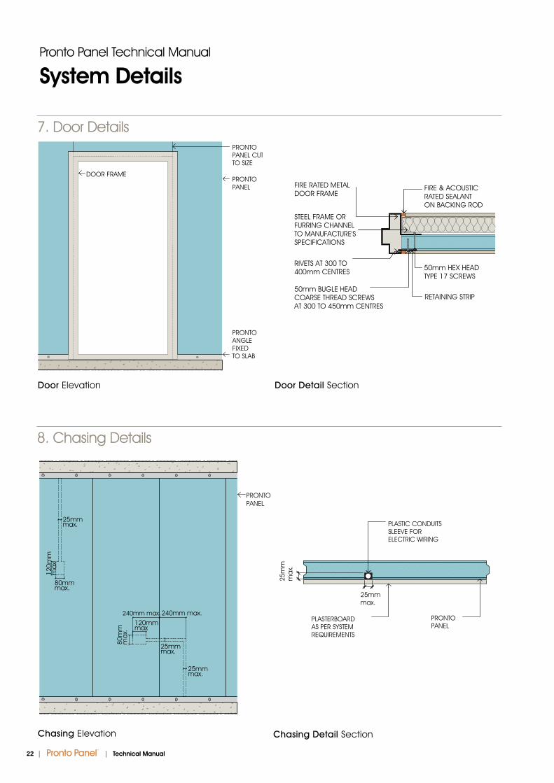
7. Door Details
Door Elevation Door Detail Section
DOOR FRAME
PRONTOPANEL CUT TO SIZE
PRONTOPANEL
PRONTOANGLEFIXED TO SLAB
FIRE & ACOUSTIC RATED SEALANT ON BACKING ROD
RETAINING STRIP50mm BUGLE HEAD COARSE THREAD SCREWS AT 300 TO 450mm CENTRES
50mm HEX HEAD TYPE 17 SCREWS
STEEL FRAME OR FURRING CHANNEL TO MANUFACTURE'SSPECIFICATIONS
RIVETS AT 300 TO400mm CENTRES
FIRE RATED METAL DOOR FRAME
8. Chasing Details
Chasing Elevation Chasing Detail Section
25mmmax.
25m
mm
ax.
PLASTIC CONDUITS SLEEVE FOR ELECTRIC WIRING
PLASTERBOARDAS PER SYSTEMREQUIREMENTS
PRONTOPANEL
25mmmax.
25mmmax.
25mmmax.
120mmmax
120m
mm
ax
240mm max.240mm max.
80m
mm
ax.
80mmmax.
PRONTOPANEL
22 | | Technical Manual
Pronto Panel Technical Manual
System Details
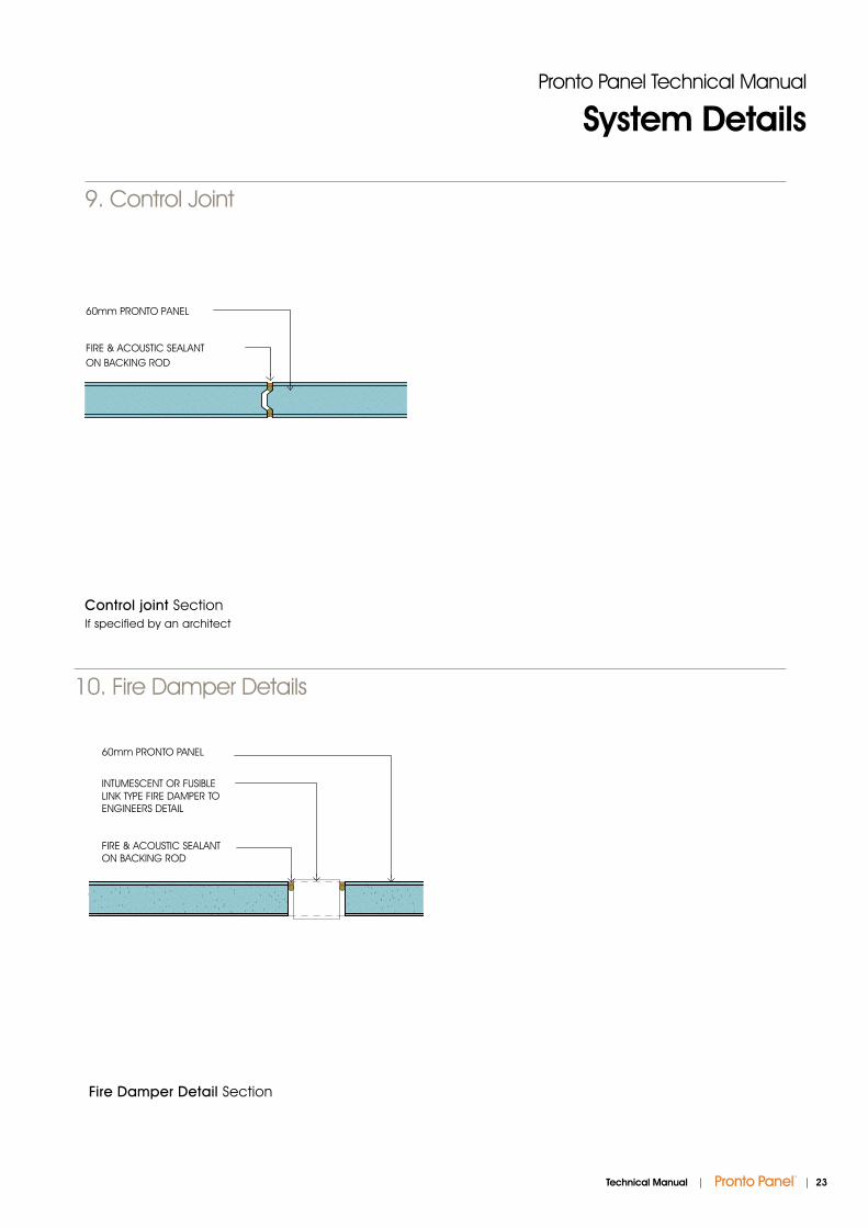
10. Fire Damper Details
60mm PRONTO PANEL
INTUMESCENT OR FUSIBLE LINK TYPE FIRE DAMPER TO ENGINEERS DETAIL
FIRE & ACOUSTIC SEALANT ON BACKING ROD
Fire Damper Detail Section
Control joint Section If specified by an architect
9. Control Joint
60mm PRONTO PANEL
FIRE & ACOUSTIC SEALANTON BACKING ROD
CONTROL JOINT - 5SECTION - SCALE 1:5
| 23Technical Manual |
24 | | Technical Manual
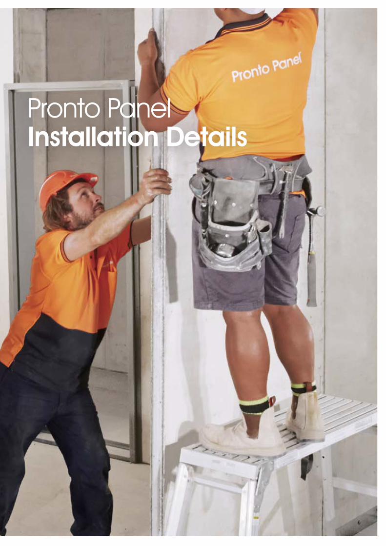
Pronto PanelInstallation Details

Delivery on Site
Pronto Panels are wrapped and strapped on pallets for delivery to site. Each pallet, containing 12 panels, is loaded by forklift onto trucks for delivery.
Pronto Panel can be unloaded either by forklift or a boom crane. The panels must be stored on site in areas where they will not be immersed in pooled water and clear of possible damage that could be caused by site movement and construction. The packs of Pronto Panels come wrapped with plastic sheeting and should remain covered during site storage.
Pronto Panel Adhesive bags are plastic wrapped and packaged on a pallet and must be stored in dry conditions. Shelf-life of Pronto Panel Adhesive is 12 months.
Pronto Panel Technical Manual
Delivery on Site
Pronto Panel Safety
1. Panel Content Pronto Panel contains no toxic
or volatile components. While the product contains polystyrene aggregates, they are coated with sufficient cement based matrix that they do not burn or emit dangerous volatile compounds in a fire situation.
2. Cutting/Drilling Cutting or drilling of the panels
will liberate dust which must be controlled by suitable means. A suitable saw is a Makita 5057KB 1400W 185mm (7-1/4”) Fibre Cement Dustless Circular Saw. It should be attached to an appropriate dust extraction system for minimal dust generation whilst cutting.
3. Pronto Panel Adhesive The Pronto Panel Adhesive
contains both cement powder and fine sand. This may constitute a hazard during use. Suitable respiratory protection, eye protection and hand protection must be worn when using this product.
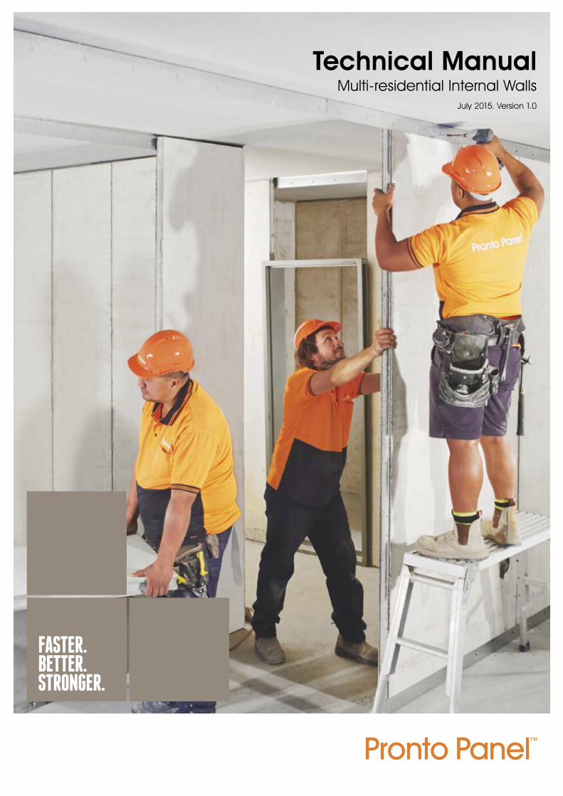
4. Safe Handling of Pronto Panel Pronto Panel weighs between
85 and 95kg, depending on length. We recommend the use of a cradle trolley to transport the panels from the pallet to the worksite. If a Pronto cradle trolley is not available the panels may be transported flat on a pallet jack or similar.
The panels do not have to be completely lifted into place for installation. The panels are to be placed with the base on the floor and the top end raised to meet the slotted angle. This reduces the load to be lifted and allows two operators to rotate the panels into position.
Safety Data Sheets for these products are available from the Pronto Panel website www.prontopanel.com.au or by contacting 13 PANELS (13 726 357)
Please see the installation section for full details of installation.
26 | | Technical Manual

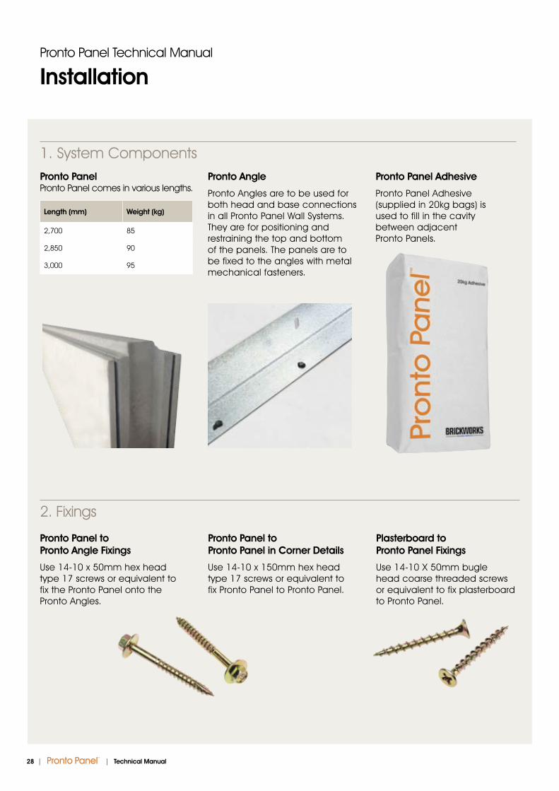
Pronto Panel Pronto Panel comes in various lengths.
Length (mm) Weight (kg)
2,700 85
2,850 90
3,000 95
Pronto Angle
Pronto Angles are to be used for both head and base connections in all Pronto Panel Wall Systems. They are for positioning and restraining the top and bottom of the panels. The panels are to be fixed to the angles with metal mechanical fasteners.
Pronto Panel Adhesive
Pronto Panel Adhesive (supplied in 20kg bags) is used to fill in the cavity between adjacent Pronto Panels.
Pronto Panel Technical Manual
Installation
Pronto Panel to Pronto Angle Fixings
Use 14-10 x 50mm hex head type 17 screws or equivalent to fix the Pronto Panel onto the Pronto Angles.
Pronto Panel to Pronto Panel in Corner Details
Use 14-10 x 150mm hex head type 17 screws or equivalent to fix Pronto Panel to Pronto Panel.
Plasterboard to Pronto Panel Fixings
Use 14-10 X 50mm bugle head coarse threaded screws or equivalent to fix plasterboard to Pronto Panel.
2. Fixings
1. System Components
28 | | Technical Manual

3. Tools Required for Installation of the Pronto Panel System
4. Installer
Pronto Panel Technical Manual
Installation
Pronto Panel installation must be carried out by qualified panel installers.
No responsibility is taken for incorrect installations of Pronto Panel.
• Chalklines for marking out wall element locations
• Electric drill mixer (recommended)
• Mixing buckets • Trowel• Grinder/steel cutting saw
• Electric screw gun• Sealant gun and fire resistant
acrylic sealant • Davco Tile and Grout Cleaner• Metal mechanical fasteners • Electric power saw with
diamond blade
| 29Technical Manual |
Pronto Panel Technical Manual
Installation
5. Installation Procedures
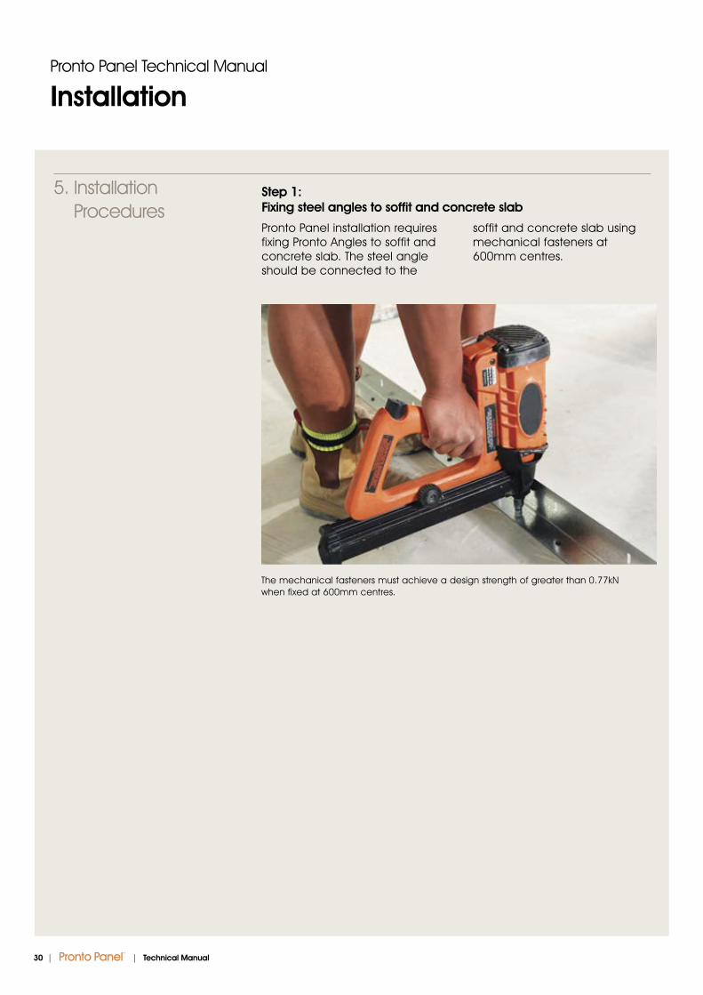
Step 1: Fixing steel angles to soffit and concrete slab
Pronto Panel installation requires fixing Pronto Angles to soffit and concrete slab. The steel angle should be connected to the
soffit and concrete slab using mechanical fasteners at 600mm centres.
The mechanical fasteners must achieve a design strength of greater than 0.77kN when fixed at 600mm centres.
30 | | Technical Manual
5 minutes
Water5L
Pronto PanelAdhesive 20kg
2 minutes 1 minute
Pronto Panel Technical Manual
Installation
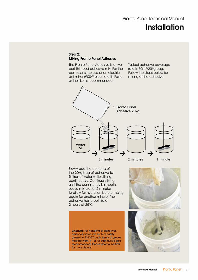
Step 2: Mixing Pronto Panel Adhesive
The Pronto Panel Adhesive is a two-part thin bed adhesive mix. For the best results the use of an electric drill mixer (900W electric drill, Festo or the like) is recommended.
Typical adhesive coverage rate is 60m2/20kg bag. Follow the steps below for mixing of the adhesive:
Slowly add the contents of the 20kg bag of adhesive to 5 litres of water while stirring continuously. Continue stirring until the consistency is smooth. Leave mixture for 2 minutes to allow for hydration before mixing again for another minute. The adhesive has a pot life of 2 hours at 25°C.
CAUTION: For handling of adhesives, personal protection such as safety glasses to AS1337 and chemical gloves must be worn. P1 or P2 dust musk is also recommended. Please refer to the SDS for more details.
| 31Technical Manual |

Step 6: Gap between panel and concrete soffit
A gap of 20mm must be left clear at the top of the panel to allow for expansion in the event of fire. The gap should be filled with backing rod and fire resistant acrylic sealant if required.
Pronto Panel Technical Manual
Installation
Step 8: Panel to Panel Connection
Position the second panel into place. Screw the second panel to steel angle.
Step 7: Adhesive to Panel
When Pronto Panel is in place, apply Pronto Panel Adhesive into the groove of the panel.
Step 3: Lifting Pronto Panel into position
With a cradle trolley, lift the panels into position.
Step 4: Fixing Pronto Panel to Pronto Angle
To fix the Pronto Panel to the steel angle, use 14-10 x 50mm hex head type 17 screws. The screws should be nominally 300 centres. At least 4 screws should be inserted per panel, 2 at the top and 2 at the bottom.
Step 5: Fixing position
These screws should be placed at the bottom of the slot in the ceiling angle and at the top of the slot in the floor angle to allow the expansion of the panel in the event of a fire.
32 | | Technical Manual

Step 10: Fire Sealing
Where fire resistance is required, backing rod and fire resistant acrylic sealant must be installed at the top of the panel to ensure good acoustic insulation and fire resistance.
Step 11: Door Frame
A steel door frame is recommended and the installation of the door frame should be coordinated to allow for solidly filling the space between the frame and Pronto Panel. Above the door way, the panel needs to be cut to size.
Step 12: Fire Dampers
Pronto Panel can accommodate a 300 x 300mm penetration for a fire damper. The gap between the fire damper and the wall is to be treated in accordance with fire damper manufacturer’s recommendations.
Step 13: Fire Collar
Fire collars are to be used when installing pipes through fire rated walls. The gap between the fire collar and the wall is to be treated in accordance with fire collar manufacturer ’s recommendations.
Step 14: Control Joints
Control joints should be placed at points of stress concentration. Examples of these locations are listed below:
• At changes in height or thickness of wall
• Near door and window openings • Near corners and
intersecting walls
Consult engineer and architect to determine the need for control joints.
Pronto Panel Technical Manual
Installation
Step 9: Smooth out Adhesive
Once the Pronto Panels are placed in position and connected, a trowel can be used to smooth out and scrape off any excess adhesives from the joints. This ensures good acoustic insulation and fire resistance.
| 33Technical Manual |

Pronto Panel Technical Manual
Warranty
Our tradition, experience and financial strength have made Brickworks Building Products the
first choice for many architects, builders and designers. Brickworks Building Products continued
commitment to quality and innovation ensures that our products will remain the benchmark for
excellence for many years to come. Pronto Panel has a warranty of 15 years as per Brickworks
Building Products’ Warranty.
Pronto Panel has a Warranty of 15 years
34 | | Technical Manual

Brickworks Building Products™ is one
of Australia’s largest and most diverse
building material manufacturers.
Under the Brickworks Building Products™
umbrella are some of Australia’s best
known building materials brands.
Our products include bricks, pavers,
masonry blocks, retaining wall systems,
precast concrete panels, concrete and
terracotta roof tiles, timber products and
specialised facade systems.
With a broad product portfolio and
manufacturing and sales facilities across
Australia, Brickworks Building Products™
is uniquely placed to service the
demands of the building industry.
With over 1,200 staff across Australia and
New Zealand, we pride ourselves on
our commitment to product and service
excellence and our leadership position.
Products and brands available from Brickworks Building Products™
Austral Bricks®
Austral Precast®
Austral Masonry® Bristile Roofing™
Auswest Timbers®
Terraçade
| 35Technical Manual |

The product images shown in this brochure give a general indication of the actual colour for your preliminary selection. We recommend that all customers see actual product samples at a selection centre prior to making final selections.
BWJ1124 07/2015 DESIGNSUITE.COM.AU
13 PANELS (13 726 357) Email: [email protected] www.prontopanel.com.au
proud supporters
Pronto Panel Head Office National
62 Belmore RoadPunchbowl NSW 2196
Trading hoursFor trading hours please call 13 PANELS (13 726 357)