Technical Information iTEMP TMT84 - … Information iTEMP ... • Rapid no-tools wiring due to...
18
TI00138R/09/en 71191804 Technical Information iTEMP ® TMT84 Dual Input Temperature Transmitter with PROFIBUS ® PA communication Application • Temperature transmitter with 2 universal input channels and PROFIBUS ® PA protocol for the conversion of different input signals into digital output signals • The iTEMP ® TMT84 stands out due to signal reliability, long-term stability, high precision and advanced diagnostics (important in critical processes) • For the highest level of safety, availability and risk reduction • Universal input usable for resistance thermometer (RTD), thermocouple (TC), resistance transmitter (Ω), voltage transmitter (mV) • DIN B style transmitter to fit in the smallest terminal heads or in remote housings in accordance with DIN EN 50446 • Optional installation in field housings even for use in Ex d areas • Mounting bracket pipe or wall for the field housing Your benefits • Easy and standardized communication via PROFIBUS ® PA Profile 3.02 • Meets the EMC requirements as per NAMUR NE21 and the recommendations of NE89 with regard to temperature transmitters with digital signal processing • Straightforward design of measuring points in Ex-areas through FISCO/FNICO conformity in accordance with IEC 600079-27 • Diagnostics information according to NAMUR NE107 • Safe operation in hazardous areas thanks to international approvals such as – FM IS, NI – CSA IS, NI – ATEX Ex ia, Ex nA (Ex nL) for intrinsically safe installation in zone 1 and zone 2 • High accuracy through sensor-transmitter matching • Reliable operation with sensor monitoring and device hardware fault recognition • Several mounting versions and sensor connection combinations • Rapid no-tools wiring due to optional spring terminal technology • Compatibility mode for easy replacement of the previous model iTEMP ® TMT184
Transcript of Technical Information iTEMP TMT84 - … Information iTEMP ... • Rapid no-tools wiring due to...

TI00138R/09/en
71191804
Technical Information
iTEMP® TMT84
Dual Input Temperature Transmitter
with PROFIBUS® PA communication
Application
• Temperature transmitter with 2 universal input
channels and PROFIBUS® PA protocol for the
conversion of different input signals into digital output
signals
• The iTEMP® TMT84 stands out due to signal
reliability, long-term stability, high precision and
advanced diagnostics (important in critical processes)
• For the highest level of safety, availability and risk
reduction
• Universal input usable for resistance thermometer
(RTD), thermocouple (TC), resistance transmitter (Ω),
voltage transmitter (mV)
• DIN B style transmitter to fit in the smallest terminal
heads or in remote housings in accordance with DIN
EN 50446
• Optional installation in field housings even for use in
Ex d areas
• Mounting bracket pipe or wall for the field housing
Your benefits
• Easy and standardized communication via
PROFIBUS® PA Profile 3.02
• Meets the EMC requirements as per NAMUR NE21
and the recommendations of NE89 with regard to
temperature transmitters with digital
signal processing
• Straightforward design of measuring points in
Ex-areas through FISCO/FNICO conformity in
accordance with IEC 600079-27
• Diagnostics information according to NAMUR NE107
• Safe operation in hazardous areas thanks to
international approvals such as
– FM IS, NI
– CSA IS, NI
– ATEX Ex ia, Ex nA (Ex nL)
for intrinsically safe installation in zone 1 and zone 2
• High accuracy through sensor-transmitter matching
• Reliable operation with sensor monitoring and device
hardware fault recognition
• Several mounting versions and sensor connection
combinations
• Rapid no-tools wiring due to optional
spring terminal technology
• Compatibility mode for easy replacement of the
previous model iTEMP® TMT184

TMT84
2 Endress+Hauser
Function and system design
Measuring principle Electronic recording and conversion of various input signals in industrial temperature measurement.
Measuring system
A0007667
Application examples
m Two sensors with measuring input (RTD or TC) in remote installation with the following advantages: drift warning,
sensor backup function and temperature-dependent switching
n Built-in head transmitter - 1 x RTD/TC or 2 x RTD/TC as redundancy
Endress+Hauser is a producer of a wide range of resistance thermometers, thermocouples and matching
thermowells.
In conjunction with these components, the temperature transmitter forms a complete measuring point for
various applications in the industrial sector.
Device architecture
A0009166-EN
System integration via PROFIBUS® PA

TMT84
Endress+Hauser 3
The temperature transmitter is a two-wire device with two measuring inputs. Using PROFIBUS® PA, the
device transfers converted signals from resistance thermometers and thermocouples in addition to other
resistance and millivolt signals. The device is powered via the PROFIBUS® PA bus and can be installed as an
intrinsically safe apparatus in zone 1 hazardous areas. The device is used for instrumentation purposes in the
terminal head form B as per DIN EN 50446. Data transfer takes place via 4 analog input (AI) function blocks:
Sensor diagnosis functions
Sensor diagnoses such as cable open circuit, short-circuit, cable corrosion, wiring error and device hardware
error are supported. In addition, the work area of the sensor and the ambient temperature are monitored.
2-channel functions
These functions increase the reliability and availability of the process values:
• Sensor backup switches to the second sensor if the primary sensor fails.
• Drift warning or alarm if the deviation between sensor 1 and sensor 2 is less than or greater than a predefined
limit value.
• Temperature-dependent switching between sensors which have advantages in different ranges.
Compatibility mode
For a easy replacement of the previous model iTEMP® TMT184 with the TMT84 a compatibility mode is
available. The switching between the standard mode and compatibility mode in the iTEMP® TMT84 is done
automatically during the connection establishment of the cyclic communication.
The Following points have to receive attention:
• Only PROFIBUS® PA-Profile 3.0 is supported.
• Only 1-channel operation possible.
• The diagnostics and status handling is equal to the previous model TMT184.
• The previous model TMT184 software locking is not available.

TMT84
4 Endress+Hauser
Input
Measured variable Temperature (temperature linear transmission behavior), resistance and voltage.
Measuring range The transmitter records different measuring ranges depending on the sensor connection and input signals (see
"Type of input").
Type of input It is possible to connect two sensors which are independent of each other. The measuring inputs are not
galvanically isolated from each other.
Type of input Designation Measuring range limits
Resistance thermometer
(RTD)
as per IEC 60751
(α = 0.00385)
as per JIS C1604-81
(α = 0.003916)
as per DIN 43760
(α = 0.006180)
as per Edison Copper Winding
No.15 (α = 0.004274)
as per Edison Curve
(α = 0.006720)
as per GOST
(α = 0.003911)
as per GOST
(α = 0.004280)
Pt100
Pt200
Pt500
Pt1000
Pt100
Ni100
Ni1000
Cu10
Ni120
Pt50
Pt100
Cu50, Cu100
Pt100 (Callendar-Van Dusen)
Polynomial nickel
Polynomial copper
-200 to 850 °C (-328 to 1562 °F)
-200 to 850 °C (-328 to 1562 °F)
-200 to 250 °C (-328 to 482 °F)
-200 to 250 °C (-238 to 482 °F)
-200 to 649 °C (-328 to 1200 °F)
-60 to 250 °C (-76 to 482 °F)
-60 to 150 °C (-76 to 302 °F)
-100 to 260 °C (-148 to 500 °F)
-70 to 270 °C (-94 to 518 °F)
-200 to 1100 °C (-328 to 2012 °F)
-200 to 850 °C (-328 to 1562 °F)
-200 to 200 °C (-328 to 392 °F)
10 to 400 Ω10 to 2000 Ω10 to 400 Ω10 to 2000 Ω10 to 400 Ω10 to 2000 Ω
• Connection type: 2-wire, 3-wire or 4-wire connection, sensor current: ≤ 0.3 mA
• For 2-wire circuit, compensation for wire resistance possible (0 to 30 Ω)
• For 3-wire and 4-wire connection, sensor wire resistance up to max. 50 Ω per
wire
Resistance transmitter Resistance Ω 10 to 400 Ω10 to 2000 Ω
Thermocouples (TC)
as per IEC 584, Part 1
as per ASTM E988
as per DIN 43710
Type B (PtRh30-PtRh6)
Type E (NiCr-CuNi)
Type J (Fe-CuNi)
Type K (NiCr-Ni)
Type N (NiCrSi-NiSi)
Type R (PtRh13-Pt)
Type S (PtRh10-Pt)
Type T (Cu-CuNi)
Type C (W5Re-W26Re)
Type D (W3Re-W25Re)
Type L (Fe-CuNi)
Type U (Cu-CuNi)
40 to +1820 °C (104 to 3308 °F)
-270 to +1000 °C (-454 to 1832 °F)
-210 to +1200 °C (-346 to 2192 °F)
-270 to +1372 °C (-454 to 2501 °F)
-270 to +1300 °C (-454 to 2372 °F)
-50 to +1768 °C (-58 to 3214 °F)
-50 to +1768 °C (-58 to 3214 °F)
-260 to +400 °C (-436 to 752 °F)
0 to +2315 °C (32 to 4199 °F)
0 to +2315 °C (32 to 4199 °F)
-200 to +900 °C (-328 to 1652 °F)
-200 to +600 °C (-328 to 1112 °F)
• Internal cold junction (Pt100)
• External cold junction: value adjustable from -40 to +85 °C (-40 to +185 °F)
• Maximum sensor resistance 10 kΩ (if the sensor resistance is greater than 10 kΩ,
an error message is output in accordance with NAMUR NE89)

TMT84
Endress+Hauser 5
When assigning both sensor inputs, the following connection combinations are possible:
Input signal Input data: The transmitter is able to receive a cyclic value and its status sent by a master via PROFIBUS® PA.
That value and status is represented and can be read acyclically.
Output
Output signal • PROFIBUS® PA in accordance with EN 50170 Volume 2, IEC 61158-2 (MBP), galvanically isolated;
• FDE (Fault Disconnection Electronic) = 0 mA
• Data transmission rate: supported baud rate = 31.25 kBit/s
• Signal coding = Manchester II
• Output data:
Available values via AI blocks: temperature (PV), temp sensor 1 + 2, terminal temperature
• In a control system the transmitter always operates as a slave and, dependent on the application, can
exchange data with one or more masters.
• In accordance with IEC 60079-27, FISCO/FNICO
Breakdown information Status message in accordance with PROFIBUS® PA Profile 3.01/3.02 specification.
Linearization/transmission
behavior
Temperature linear, resistance linear, voltage linear
Mains voltage filter 50/60 Hz
Galvanic isolation U = 2 kV AC (sensor input to the output)
Current consumption ≤ 11 mA
Switch-on delay 8 s
Voltage transmitter (mV) Millivolt transmitter (mV) -20 to 100 mV
-5 to 30 mV
Sensor input 1
RTD or
resistance
transmitter, 2-
wire
RTD or
resistance
transmitter, 3-
wire
RTD or
resistance
transmitter, 4-
wire
Thermocouple
(TC), voltage
transmitter
Sensor
input 2
RTD or resistance
transmitter, 2-wire  - Â
RTD or resistance
transmitter, 3-wire  - Â
RTD or resistance
transmitter, 4-wire- - - -
Thermocouple (TC),
voltage transmitter   Â
Type of input Designation Measuring range limits

TMT84
6 Endress+Hauser
PROFIBUS® PA basic data
Brief description of the blocks Physical Block
The Physical Block contains all the data that clearly identify and characterize the device. It is like an
electronicdevice nameplate. In addition to parameters that are needed to operate the device on the fieldbus,
the Physical Block makes other information available such as the order code, device ID, hardware revision,
software revision, device release, etc. Furthermore the display settings can be configured via the Physical Block.
Transducer Block "Sensor 1" and "Sensor 2"
The Transducer Blocks of the transmitter contain all the measurement-related and device-specific parameters
that are relevant for measuring the input variables.
Analog Input (AI)
In the AI function block, the process variables from the Transducer Blocks are prepared for subsequent
automation functions in the control system (e.g. scaling, limit value processing).
Power supply
Electrical connection
A0007285-EN
Terminal assignment of transmitter.
Supply voltage U = 9 to 32 V DC, polarity independent (max. voltage Ub = 35 V)
Manufacturer spec. ID-no.: Profile 3.0 ID-no.: Manufacturer specific GSD
1551 (Hex) 9700 (Hex)
9701 (Hex)
9702 (Hex)
9703 (Hex)
EH021551.gsd
(Profile 3.01 EH3x1551.gsd)
Profile 3.0 GSD Device address or bus address Bitmaps
Pa139700.gsd
Pa139701.gsd
Pa139702.gsd
Pa139703.gsd
126 (default) EH_1551_d.bmp
EH_1551_n.bmp
EH_1551_s.bmp
If the TMT84 operates in the compatibily mode, the device is identifying with the manufacturer
specific ID-no.: 1523 (Hex) - TMT184 in the cyclic data exchange.
-
+
+1
-2
7
6
5
4
3
1
2
7
6
5
4
3
Sensor input 2 Sensor input 1Bus connection
and supply voltage
Display connection/service interface
TC, mV
RTD, 4-, 3- and 2-wire:ΩRTD, 3- and 2-wire:Ω
TC, mV
white
red
red
white
white
red
red
TMT84
Endress+Hauser 7
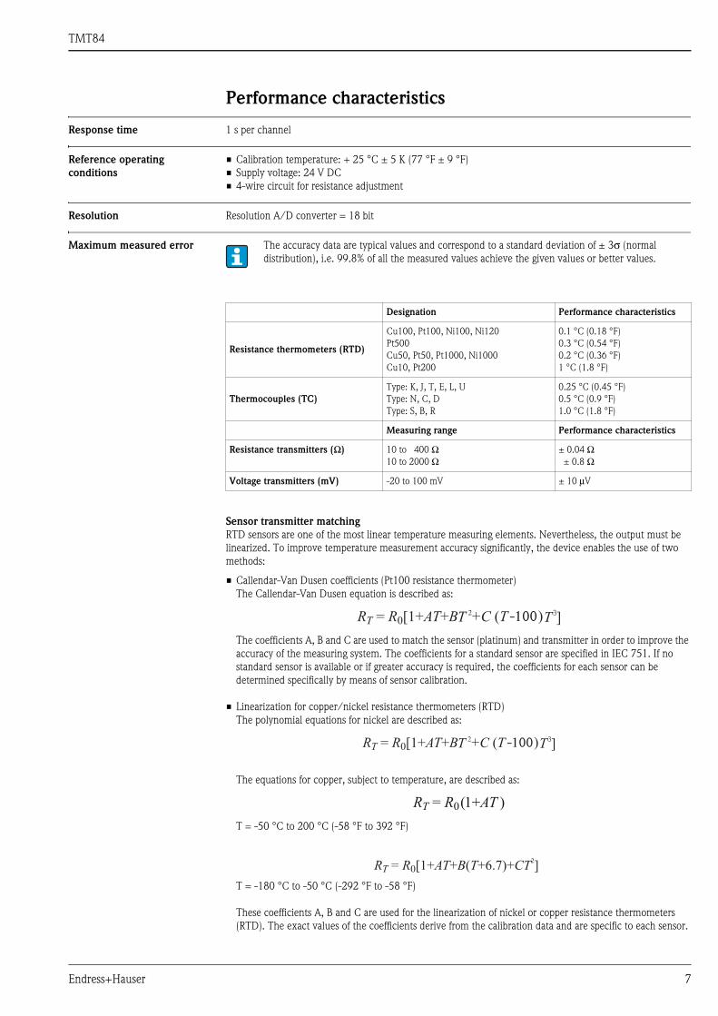
Performance characteristics
Response time 1 s per channel
Reference operating
conditions
• Calibration temperature: + 25 °C ± 5 K (77 °F ± 9 °F)
• Supply voltage: 24 V DC
• 4-wire circuit for resistance adjustment
Resolution Resolution A/D converter = 18 bit
Maximum measured error
Sensor transmitter matching
RTD sensors are one of the most linear temperature measuring elements. Nevertheless, the output must be
linearized. To improve temperature measurement accuracy significantly, the device enables the use of two
methods:
• Callendar-Van Dusen coefficients (Pt100 resistance thermometer)
The Callendar-Van Dusen equation is described as:
The coefficients A, B and C are used to match the sensor (platinum) and transmitter in order to improve the
accuracy of the measuring system. The coefficients for a standard sensor are specified in IEC 751. If no
standard sensor is available or if greater accuracy is required, the coefficients for each sensor can be
determined specifically by means of sensor calibration.
• Linearization for copper/nickel resistance thermometers (RTD)
The polynomial equations for nickel are described as:
The equations for copper, subject to temperature, are described as:
T = -50 °C to 200 °C (-58 °F to 392 °F)
T = -180 °C to -50 °C (-292 °F to -58 °F)
These coefficients A, B and C are used for the linearization of nickel or copper resistance thermometers
(RTD). The exact values of the coefficients derive from the calibration data and are specific to each sensor.
The accuracy data are typical values and correspond to a standard deviation of ± 3σ (normal
distribution), i.e. 99.8% of all the measured values achieve the given values or better values.
Designation Performance characteristics
Resistance thermometers (RTD)
Cu100, Pt100, Ni100, Ni120
Pt500
Cu50, Pt50, Pt1000, Ni1000
Cu10, Pt200
0.1 °C (0.18 °F)
0.3 °C (0.54 °F)
0.2 °C (0.36 °F)
1 °C (1.8 °F)
Thermocouples (TC)
Type: K, J, T, E, L, U
Type: N, C, D
Type: S, B, R
0.25 °C (0.45 °F)
0.5 °C (0.9 °F)
1.0 °C (1.8 °F)
Measuring range Performance characteristics
Resistance transmitters (Ω) 10 to 400 Ω10 to 2000 Ω
± 0.04 Ω± 0.8 Ω
Voltage transmitters (mV) -20 to 100 mV ± 10 μV
3-100
3-100

TMT84
8 Endress+Hauser
Sensor transmitter matching using one of the above-named methods significantly improves the temperature
measurement accuracy of the entire system. This is due to the fact that to calculate the temperature measured,
the transmitter uses the specific data pertaining to the connected sensor instead of using the standardized
sensor curve data.
Non-repeatability As per EN 61298-2
Long-term stability ≤ 0.1 °C/year (≤ 0.18 °F/year) in reference operating conditions
Influence of ambient tempera-
ture (temperature drift)
Example Pt100: 0.00385 x 100 Ω/K = 0.385 Ω/K
Example of calculating the measured error with ambient temperature drift:
• Input temperature drift ϑ = 10 K (18 °F), Pt100, measuring range 0 to 100 °C (32 to 212 °F)
• Maximum process temperature: 100 °C (212 °F)
• Measured resistance value: 138.5 Ω (DIN EN 60751) at maximum process temperature
Typical temperature drift in Ω: (0.001% of 138.5 Ω) * 10 = 0.01385 ΩConversion to Kelvin: 0.01385 Ω / 0.385 Ω/K = 0.04 K (0.054 °F)
Influence of reference point
(cold junction)
Pt100 DIN EN 60751 Cl. B, internal reference point for thermocouples TC
Physical input measuring range of sensors Non-repeatability
10 to 400 Ω Cu10, Cu50, Cu100, Pt50, Pt100, Ni100, Ni120 15 mΩ
10 to 2000 Ω Pt200, Pt500, Pt1000, Ni1000 100 ppm x measured value
-20 to 100 mV Thermocouples type: C, D, E, J, K, L, N, U 4 μV
-5 to 30 mV Thermocouples type: B, R, S, T 3 μV
Impact on accuracy when ambient temperature changes by 1 K (1.8 °F):
Input 10 to 400 Ω 0.001% of the measured value, min. 1 mΩ
Input 10 to 2000 Ω 0.001% of the measured value, min. 10 mΩ
Input -20 to 100 mV 0.001% of the measured value, min. 0.2 μV
Input -5 to 30 mV 0.001% of the measured value, min. 0.2 μV
Typical sensitivity of resistance thermometers
Pt: 0.00385 * Rnom/K Cu: 0.0043 * Rnom/K Ni: 0.00617 * Rnom/K
Typical sensitivity of thermocouples
B: 9 μV/K at
1000 °C (1832 °F)
C: 18 μV/K at
1000 °C (1832 °F)
D: 20 μV/K at
1000 °C (1832 °F)
E: 81 μV/K at
500 °C (932 °F)
J: 56 μV/K at
500 °C (932 °F)
K: 43 μV/K at
500 °C (932 °F)
L: 60 μV/K at
500 °C (932 °F)
N: 38 μV/K at
500 °C (932 °F)
R: 13 μV/K at
1000 °C (1832 °F)
S: 11 μV/K at
1000 °C (1832 °F)
T: 46μV/K at
100 °C (212 °F)
U: 70 μV/K at
500 °C (932 °F)
TMT84
Endress+Hauser 9
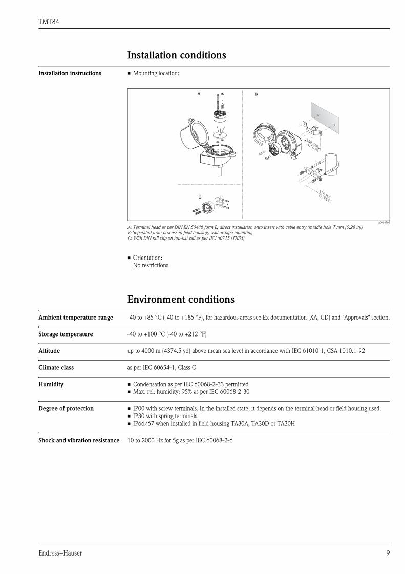
Installation conditions
Installation instructions • Mounting location:
A0016762
A: Terminal head as per DIN EN 50446 form B, direct installation onto insert with cable entry (middle hole 7 mm (0.28 in))
B: Separated from process in field housing, wall or pipe mounting
C: With DIN rail clip on top-hat rail as per IEC 60715 (TH35)
• Orientation:
No restrictions
Environment conditions
Ambient temperature range -40 to +85 °C (-40 to +185 °F), for hazardous areas see Ex documentation (XA, CD) and "Approvals" section.
Storage temperature -40 to +100 °C (-40 to +212 °F)
Altitude up to 4000 m (4374.5 yd) above mean sea level in accordance with IEC 61010-1, CSA 1010.1-92
Climate class as per IEC 60654-1, Class C
Humidity • Condensation as per IEC 60068-2-33 permitted
• Max. rel. humidity: 95% as per IEC 60068-2-30
Degree of protection • IP00 with screw terminals. In the installed state, it depends on the terminal head or field housing used.
• IP30 with spring terminals
• IP66/67 when installed in field housing TA30A, TA30D or TA30H
Shock and vibration resistance 10 to 2000 Hz for 5g as per IEC 60068-2-6
A B
C
120 mm(4.72 in)
120 mm(4.72 in)

TMT84
10 Endress+Hauser
Electromagnetic compatibility
(EMC)
CE EMC compliance
The device meets all of the requirements mentioned in IEC 61326-1, 2007 and NAMUR NE21:2006.
This recommendation is a consistent determination whether the devices used in laboratories and in process
control systems are immune to interference, thus increasing their functional safety.
Measuring category Measuring category II as per IEC 61010-1. The measuring category is provided for measuring on power circuits
that are directly connected electrically with the low-voltage network.
Degree of contamination Pollution degree 2 as per IEC 61010-1.
Mechanical construction
Design, dimensions Specifications in mm (in)
Head transmitter
A0007301
Model with screw terminals
Pos. A: Spring range L ≥5 mm (not applicable to US - M4 mounting screws)
Pos. B: Fixing elements for detachable measured value display
Pos. C: Interface for contacting measured value display
A0007672
Model with spring terminals. The same dimensions except for height of housing.
Field housings
All terminal heads have an internal shape and size in accordance with DIN EN 50446, flat face and a
thermometer connection of M24x1.5. Cable glands: M20x1.5
ESD (electrostatic discharge) IEC 61000-4-2 6 kV cont., 8 kV air
Electromagnetic fields IEC 61000-4-3 0.08 to 4 GHz 10 V/m
Burst (fast transients) IEC 61000-4-4 1 kV
Surge IEC 61000-4-5 1 kV asym.
Conducted RF IEC 61000-4-6 0.01 to 80 MHz 10 V

TMT84
Endress+Hauser 11
TA30A Specification
A0009820
• Two cable entries
• Temperature: -50 °C to +150 °C (-58 °F to +302 °F) without
cable gland
• Material: aluminum, polyester powder coated
Seals: silicone
• Cable entry incl. glands: ½"NPT and M20x1.5
• Head color: blue RAL 5012
• Cap color: gray RAL 7035
• Weight: 330 g (11.64 oz)
TA30A with display window in cover Specification
A0009821
• Two cable entries
• Temperature: -50 °C to +150 °C (-58 °F to +302 °F) without
cable gland
• Material: aluminum, polyester powder coated
Seals: silicone
• Cable entry incl. glands: ½"NPT und M20x1.5
• Head color: blue RAL 5012
• Cap color: gray RAL 7035
• Weight: 420 g (14.81 oz)
TA30H Specification
A0009832
• Flameproof (XP) version, explosion-protected, captive screw cap,
with two cable entries
• Temperature: -50 °C to +150 °C (-58 °F to +302 °F) for rubber
seal without cable gland (observe max. permitted temperature of
the cable gland!)
• Material: aluminum; polyester powder coated
• Cable entry glands: ½"NPT, M20x1.5
• Head color: blue RAL 5012
• Cap color: gray RAL 7035
• Weight: 640 g (22.6 oz)
107.5 (4.23)
68
.5 (
2.7
)28
(1.1)78 (3.1)
15
.5 (
0.6
)
125 (4.92)
89
.5 (
3.5
2)
28
(1.1)78 (3.01)
20
.5 (
0.8
)

TMT84
12 Endress+Hauser
Weight • Head transmitter: approx. 40 to 50 g (1.4 to 1.8 oz)
• Field housing: see specifications
Material All materials used are RoHS-compliant.
Head transmitter
• Housing: Polycarbonate (PC), complies with UL94 HB flammability standard (HB: horizontal burning test)
• Terminals
Screw terminals: Nickel-plated brass and gold-plated contact
Spring terminals: Tin-plated brass, contact spring V2A
• Potting: WEVO PU 403 FP / FL, according to UL94 V0 flammability standard (V0: vertical burning test)
TA30H with display window in cover Specification
A0009831
• Flameproof (XP) version, explosion-protected, captive screw cap,
with two cable entries
• Temperature: -50 °C to +150 °C (-58 °F to +302 °F) for rubber
seal without cable gland (observe max. permitted temperature of
the cable gland!)
• Material: aluminum; polyester powder coated
• Cable entry glands: ½"NPT, M20x1.5
• Head color: blue RAL 5012
• Cap color: gray RAL 7035
• Weight: 860 g (30.33 oz)
TA30D Specification
A0009822
• Two cable entries
• Temperature: -50 °C to +150 °C (-58 °F to +302 °F) without
cable gland
• Material: aluminum, polyester powder coated
Seals: silicone
• Cable entry incl. glands: ½"NPT, M20x1.5
• Two head transmitters can be mounted. In the standard version,
one transmitter is mounted in the terminal head cover and an
additional terminal block is installed directly on the insert.
• Head color: blue RAL 5012
• Cap color: gray RAL 7035
• Weight: 390 g (13.75 oz)
Maximum ambient temperature for cable glands and fieldbus connectors
Type Temperature range
Cable gland polyamide ½" NPT, M20x1.5
(non-Ex)
-40...+100 °C (-40...+212 °F)
Cable gland polyamide M20x1.5
(for dust ignition-proof area)
-20...+95 °C (-4...+203 °F)
Cable gland brass ½" NPT, M20x1.5
(for dust ignition-proof area)
-20...+130 °C (-4...+266 °F)
Fieldbus connector (M12x1 PA, 7/8" FF) -40...+105 °C (-40...+221 °F)
107.5 (4.23)
110 (
4.3
)
28
(1.1)78 (3.1)
15.5
(0.6
)

TMT84
Endress+Hauser 13
Field housing: see specifications
Terminals Choice of screw or spring terminals (see "Design, dimensions" diagram) for sensor and fieldbus wires:
Human interface
Display and operating
elements
There are no display or operating elements present at the transmitter.
Optional the plug-on display TID10 can be used in connection with the transmitter. It will display information
regarding the actual measured value and the measurement point identification. In the event of a fault in the
measurement chain this will be displayed in inverse color showing the channel ident and diagnostics code.
DIP-switches can be found on the rear of the display. This enables the hardware set-up such as the PROFIBUS®
device address.
a0009818
Pluggable display TID10
If the transmitter is installed in a field housing and used with a display, a housing with glas window needs to
be used.
Remote operation The configuration of PROFIBUS® PA functions and of device-specific parameters is performed via fieldbus
communication. Special configuration systems provided by various manufacturers are available for this
purpose.
Sources of supply of the device data files (GSD) and device drivers:
• GSD-file: www.endress.com (→ Download → Software)
Terminals version Wire version Conductor cross-section
Screw terminals (with latches at the
fieldbus terminals for easy connection of a
handheld terminal, e.g. DXR375)
Rigid or flexible ≤ 2.5 mm2 (14 AWG)
Spring terminals
Stripped length = min. 10 mm (0.39 in)
Rigid or flexible 0.2...1.5 mm2 (24...16 AWG)
Flexible with wire-end ferrules
without plastic ferrule
0.25...1.5 mm2 (24...16 AWG)
Flexible with wire-end ferrules
with plastic ferrule
0.25...0.75 mm2 (24...18 AWG)
No ferrules have to be used when connecting flexible wires to spring terminals.
Configuration software
Endress+Hauser FieldCare (DTM)
SIMATIC PDM (EDD)

TMT84
14 Endress+Hauser
• Profile GSD-file: www.profibus.com
• FieldCare/DTM: www.endress.com (→ Automation → Fieldbus → Fieldbus device integration)
• SIMATIC PDM: www.endress.com (→ Automation → Fieldbus → Fieldbus device integration) or
www.fielddevices.com
Bus address The device address or bus address is set up either with the configuration software or via DIP switches on the
optional display.
Certificates and approvals
CE-Mark The device meets the legal requirements of the EC directives. Endress+Hauser confirms that the device has
been successfully tested by applying the CE mark.
Hazardous area approvals ATEX approval
Application:
• Equipment category: potentially explosive gas and air mixtures (G)
• Category 1 zone 0, 1 or 2
TMT84 ATEX II 1G Ex ia IIC T6/T5/T4
Power supply (Terminals + and -) Ui ≤ 17.5 V DC
Ii ≤ 500 mA
Ci ≤ 5 nF
Li = negligibly small
or Ui ≤ 24 V DC
Ii ≤ 250 mA
Suitable for connecting to a fieldbus system as per the FISCO/FNICO model
Sensor circuit (Terminals 3 to 7) U0 ≤ 7.2 V DC
I0 ≤ 25.9 mA
P0 ≤ 46.7 mW
Ci = negligibly small
Li = negligibly small
Max. connection data Ex ia IIC
Ex ia IIB
Ex ia IIA
L0 = 20 mH
L0 = 50 mH
L0 = 100 mH
C0 = 0.7 μF
C0 = 4.6 μF
C0 = 6.0 μF
Temperature range
T6
T5
T4
Zone 1, 2:
Ta = -40 °C to +55 °C (-40 °F to 130 °F)
Ta = -40 °C to +70 °C (-40 °F to 158 °F)
Ta = -40 °C to +85 °C (-40 °F to 185 °F)
Zone 0:
Ta = -20 °C to +40 °C (-4 °F to 104 °F)
Ta = -20 °C to +50 °C (-4 °F to 122 °F)
Ta = -20 °C to +60 °C (-4 °F to 140 °F)
For zone 0: potentially explosive steam and air mixtures may only occur under following
atmospheric conditions:
• - 20 °C ≤ Ta ≤ +60 °C (- 4 °F ≤ Ta ≤ +140 °F)• 0.8 bar ≤ p ≤ 1.1 bar (11.6 psi ≤ p ≤ 16 psi)
TMT84 ATEX
• II 2G Ex d IIC T6…T4 Gb
• II 2D Ex tb IIIC T85 °C…T105 °C Db
IEC
• Ex d IIC T6…T4 Gb
• Ex tb IIIC T85 °C…T105 °C Db
Power supply (terminals + and -) U ≤ 35 V DC
Output PROFIBUS® PA
Current consumption ≤ 11 mA
Temperature range T6
T5
T4
-40 °C ≤ Ta ≤ +65 °C
-40 °C ≤ Ta ≤ +80 °C
-40 °C ≤ Ta ≤ +85 °C

TMT84
Endress+Hauser 15
Application (ATEX II 3G Ex nA II T6/T5/T4):
• Equipment category: potentially explosive gas and air mixtures (G)
• Category zone 2
Application (ATEX II 3D):
• Equipment category: potentially explosive dust and air mixtures (D)
• Category zone 22
FM approval
Labeling: IS / I / 1 / ABCD / T4, Entity* or FISCO*;
I / 0 / AEx ia IIC / T4 Ta, Entity* or FISCO*
NI / I / 2 / ABCD / T4, NIFW* or FNICO*;
FM XP, NI, DIP I, II, III / 1+2 / A-G
*= Entity, FISCO, NIFW and FNICO parameters in accordance with control drawings (CD)
Application:
• Intrinsic safety
• Non-incendive
For connection data see table on ATEX approval ATEX II 1G
CSA approval (Canadian Standard Association)
Labeling:
Class I, Div. 1, Groups A, B, C, D, Entity* or FISCO*;
Maximum suface temperature housing T85°C
T100°C
T105°C
-40 °C ≤ Ta ≤ +65 °C
-40 °C ≤ Ta ≤ +80 °C
-40 °C ≤ Ta ≤ +85 °C
TMT84 ATEX II 3G Ex nA II T6/T5/T4
ATEX II 3D
Power supply (terminals + and -) U ≤ 35 V DC
Output PROFIBUS® PA
Current consumption ≤ 11 mA
Temperature range T6
T5
T4
Ta = -40 °C to + 55 °C (-40 °F to 130 °F)
Ta = -40 °C to + 70 °C (-40 °F to 158 °F)
Ta = -40 °C to + 85 °C (-40 °F to 185 °F)
TMT84 II 3G Ex nL IIC T6/T5/T4
Power supply
(terminals + and -)
Ui ≤ 32 V DC
Ci ≤ 5 nF
Li ≤ 10 μH
Applicable for connection to a Fieldbus system according to FNICO-model
Sensor circuit (terminals 3 to 7) Uo ≤ 7.2 VDC
Io ≤ 25.9 mA
Po ≤ 46.7 mW
Max. connection values Ex nL IIC
Ex nL IIB
Ex nL IIA
Lo = 20 mH
Lo = 50 mH
Lo = 100 mH
Co = 0.97 μF
Co = 4.6 μF
Co = 6 μF
Temperature range T6
T5
T4
Ta = -40 °C to + 55 °C
Ta = -40 °C to + 70 °C
Ta = -40 °C to + 85 °C
TMT84 ATEX
• II 2G Ex d IIC T6…T4 Gb
• II 2D Ex tb IIIC T85 °C…T105 °C Db
IEC
• Ex d IIC T6…T4 Gb
• Ex tb IIIC T85 °C…T105 °C Db
TMT84
16 Endress+Hauser
Ex ia IIC
Class I, Div.2, Groups A, B, C, D, NIFW* or FNICO*;
Ex nA IIC
CSA XP, NI, DIP I, II, III / 1+2 / A-G
*= Entity, FISCO, NIFW and FNICO parameters in accordance with control drawings (CD)
Application:
• Intrinsic safety
• Non-incendive
For connection data see table on ATEX approval ATEX II 1G
For further details on the available Ex versions (ATEX, CSA, FM, etc.), please contact your nearest
Endress+Hauser sales organisation. All relevant data for hazardous areas can be found in separate Ex
documentation. If required, please request copies from us or your Endress+Hauser sales organisation.
UL Recognized component to UL61010-1
Other standards and
guidelines
• IEC 60529:
Degrees of protection through housing (IP code)
• IEC 61158-2:
Fieldbus standard
• IEC 61326-1:2007:
Electromagnetic compatibility (EMC requirements)
• IEC 60068-2-27 and IEC 60068-2-6:
Shock and vibration resistance
• NAMUR
International user association of automation technology in process industries
CSA GP CSA General Purpose
Certification PROFIBUS® PA The temperature transmitter is certified and registered by the PNO (PROFIBUS® user organization e.V.). The
device thus meets all the requirements of the specifications following:
• Certified according to PROFIBUS® PA Profile 3.02
• The device can also be operated with certified devices of other manufacturers (interoperability)
Ordering information
Detailed ordering information is available from the following sources:
• In the Product Configurator on the Endress+Hauser website:
www.endress.com → Select country→ Instruments → Select device→ Product page function: Configure
this product
• From your Endress+Hauser Sales Center:
www.endress.com/worldwide
Product Configurator - the tool for individual product configuration:
• Up-to-the-minute configuration data
• Depending on the device: Direct input of measuring point-specific information such as measuring range or
operating language
• Automatic verification of exclusion criteria
• Automatic creation of the order code and its breakdown in PDF or Excel output format
• Ability to order directly in the Endress+Hauser Online Shop

TMT84
Endress+Hauser 17
Accessories
The following accessories are contained in the scope of delivery:
• Multi-language Brief Operating Instructions as hard copy
• Supplementary documentation ATEX:
ATEX Safety instructions (XA), Control Drawings (CD)
• Operating Instructions on CD-ROM
• Mounting material for head transmitter
• Mounting material for field housings (pipe or wall mounting)
Documentation
• Operating instructions "iTEMP® TMT84" (BA00257R/09/en) on CD-ROM and associated Brief Operating
Instructions "iTEMP® TMT84" (KA00258R/09/a2)
• Ex supplementary documentation:
ATEX II 1G Ex ia IIC: XA069R/09/a3
ATEX II 3G Ex nA II: XA073R/09/a3
ATEX II 3D Ex tD (iaD) A22: XA074R/09/a3
ATEX II 2(1)G Ex ia IIC: XA01012T/09/a3
ATEX II 2G Ex d IIC and ATEX II 2D Ex tb IIIC: XA01007T/09/a3
• Operating instructions "Display TID10" (BA262R/09/c4)
• Guidelines for planning and commissioning "PROFIBUS® DP/PA" (BA034S/04/en)
Type Order code
Display TID10 for Endress+Hauser transmitters iTEMP® TMT8x, pluggable TID10-xx
Field housing TA30x for Endress+Hauser head transmitter TA30x-xx
DIN rail clip according to IEC 60715 (TH35) for head transmitter mounting 51000856
Standard - DIN mounting set (2 screws + springs, 4 securing disks and 1
display connector cover)
71044061
US - M4 mounting screws (2 screws M4 and 1 display connector cover) 71044062
Fieldbus connector
(PROFIBUS® PA):
Threaded connection
• M20x1.5
• NPT ½" • M20x1.5
Cable connecting thread
• M12
• M12
• 7/8"
71090687
71005802
71089147
Stainless steel wall mounting bracket
Stainless steel pipe mounting bracket
71123339
71123342

TMT84
Instruments International
Endress+HauserInstruments International AGKaegenstrasse 24153 ReinachSwitzerland
Tel.+41 61 715 81 00Fax+41 61 715 25 [email protected]
TI00138R/09/EN/04.12
71191804
FM9.0