
Technical Information and Schuh CA5-700... · Technical Information The CA5-550 has been replaced...
15
A135 SSNA9000 Contactors A CA5 Discount Schedule A-1 Technical Information CA5 Contactors Technical Information ➊ The CA5-550 has been replaced by the CA6-420-EI contactor. CA5-550 contactors are available by special order if required for their higher AC1 ratings. ➋ The CA5-700 & 860 has been replaced by the CA6-630 & 860 contactor. CA5-700 & 860 contactors are available by special order. ➌ At rated voltage (415V) and rated current: Life span –25%. CA5- 550 ➊ CA5- 700 ➌ CA5- 860 ➋ CA5- 1000 CA5- 1200 Rated Insulation Voltage U i to IEC947-1 [V] 1000V 1000V 1000V 690V 690V UL/CSA [V] 600V Rated Impulse Voltage U imp CA5-550 / 700 / 860 [kV] 3.5 CA5-1000 / 1200 [kV] 2.5 Rated Voltage Ue-Main Contacts AC 50/60Hz [V] 220/230, 240, 380/400,415,500,660/690 (1000V - CA5-550 to 860) DC [V] 24, 48, 110, 220, 440V Operating Frequency for AC Loads [Hz] 50/60Hz 180/hr. for 0.25s start time - 42/hr. for 1s start time Switching Motor Loads Standard IEC Ratings AC-2, AC-3 230/240V [A] 550 700 860 1000 1200 DOL & Reversing 400/415V [A] 550 700 860 1000 1200 50Hz/60˚ C 500V [A] 550 700 860 1000 1200 690V [A] 500 630 700 860 1000 230V [kW] 179 228 280 326 391 240V [kW] 187 238 293 340 408 400V [kW] 312 414 509 592 710 415V [kW] 324 430 528 628 737 500V [kW] 407 518 636 756 888 690V [kW] 510 657 730 897 1043 UL/CSA 200V [A] 414 552 692 ~ 1185 DOL & Reversing 230V [A] 360 602 722 ~ 1130 60Hz 460 V [A] 414 590 708 ~ 1062 3∅ 575 V [A] 336 472 576 ~ 864 200 V [HP] 150 200 250 ~ 450 230 V [HP] 150 250 300 ~ 450 460 V [HP] 350 500 600 ~ 900 575 V [HP] 350 500 600 ~ 900 AC4 -200,000 Op. Cycles 230/240V [A] 140 180 210 260 300 50Hz 400/415V [A] 140 180 210 260 300 500V [A] 125 155 190 240 275 690V [A] 110 145 165 180 210 1000V [A] 95 120 145 ~ ~ 230V [kW] 45 57 67 83 97 240V [kW] 47 60 70 87 101 400V [kW] 78 101 118 146 170 415V [kW] 81 105 122 151 176 500V [kW] 86 106 132 170 195 690V [kW] 100 135 155 165 190 1000V [kW] 130 170 205 ~ ~ AC4 -200,000 Op. Cycles (25,000) 230/240V [A] 360 430 520 (630) (700) Squirrel-cage motors with reversing 400/415V ➌ [A] 350 420 520 (630) (700) and jogging 230V [kW] 116 139 170 (205) (228) 240V [kW] 120 151 177 (214) (245) 400V [kW] 198 238 295 (357) (414) 415V [kW] 206 247 300 (359) (424)
Transcript of Technical Information and Schuh CA5-700... · Technical Information The CA5-550 has been replaced...

A135
SSNA
9000
Cont
acto
rs
A
CA5
Discount Schedule A-1
Technical InformationCA5 Contactors
Technical Information
➊ The CA5-550 has been replaced by the CA6-420-EI contactor. CA5-550 contactors are available by special order if required for their higher AC1 ratings.
➋ The CA5-700 & 860 has been replaced by the CA6-630 & 860 contactor. CA5-700 & 860 contactors are available by special order.
➌ At rated voltage (415V) and rated current: Life span –25%.
CA5-550 ➊
CA5-700 ➌
CA5-860 ➋
CA5-1000
CA5-1200
Rated Insulation Voltage Ui
to IEC947-1 [V] 1000V 1000V 1000V 690V 690VUL/CSA [V] 600V
Rated Impulse Voltage Uimp
CA5-550 / 700 / 860 [kV] 3.5CA5-1000 / 1200 [kV] 2.5
Rated Voltage Ue-Main ContactsAC 50/60Hz [V] 220/230, 240, 380/400,415,500,660/690 (1000V - CA5-550 to 860)DC [V] 24, 48, 110, 220, 440V
Operating Frequency for AC Loads [Hz] 50/60Hz 180/hr. for 0.25s start time - 42/hr. for 1s start time
Switching Motor LoadsStandard IEC RatingsAC-2, AC-3 230/240V [A] 550 700 860 1000 1200
DOL & Reversing 400/415V [A] 550 700 860 1000 120050Hz/60˚ C 500V [A] 550 700 860 1000 1200
690V [A] 500 630 700 860 1000230V [kW] 179 228 280 326 391240V [kW] 187 238 293 340 408400V [kW] 312 414 509 592 710415V [kW] 324 430 528 628 737500V [kW] 407 518 636 756 888690V [kW] 510 657 730 897 1043
UL/CSA 200V [A] 414 552 692 ~ 1185DOL & Reversing 230V [A] 360 602 722 ~ 113060Hz 460 V [A] 414 590 708 ~ 1062 3∅ 575 V [A] 336 472 576 ~ 864
200 V [HP] 150 200 250 ~ 450230 V [HP] 150 250 300 ~ 450460 V [HP] 350 500 600 ~ 900575 V [HP] 350 500 600 ~ 900
AC4 -200,000 Op. Cycles 230/240V [A] 140 180 210 260 30050Hz 400/415V [A] 140 180 210 260 300
500V [A] 125 155 190 240 275690V [A] 110 145 165 180 2101000V [A] 95 120 145 ~ ~230V [kW] 45 57 67 83 97240V [kW] 47 60 70 87 101400V [kW] 78 101 118 146 170415V [kW] 81 105 122 151 176500V [kW] 86 106 132 170 195690V [kW] 100 135 155 165 1901000V [kW] 130 170 205 ~ ~
AC4 -200,000 Op. Cycles (25,000) 230/240V [A] 360 430 520 (630) (700)Squirrel-cage motors with reversing 400/415V ➌ [A] 350 420 520 (630) (700)and jogging 230V [kW] 116 139 170 (205) (228)
240V [kW] 120 151 177 (214) (245)400V [kW] 198 238 295 (357) (414)415V [kW] 206 247 300 (359) (424)
A136
SSNA
9000
Cont
acto
rs
A
CA5
Discount Schedule A-1
Electrical Data
Technical InformationCA5 Contactors
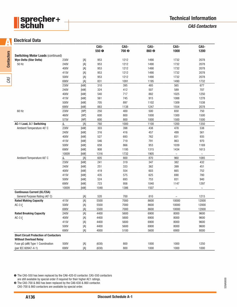
➊ The CA5-550 has been replaced by the CA6-420-EI contactor. CA5-550 contactors are still available by special order if required for their higher AC1 ratings.
➋ The CA5-700 & 860 has been replaced by the CA6-630 & 860 contactor. CA5-700 & 860 contactors are available by special order.
CA5-550 ➊
CA5-700 ➋
CA5-860 ➋
CA5-1000
CA5-1200
Switching Motor Loads (continued)Wye-Delta (Star Delta) 230V [A] 953 1212 1490 1732 2078
50 Hz 240V [A] 953 1212 1490 1732 2078400V [A] 953 1212 1490 1732 2078415V [A] 953 1212 1490 1732 2078500V [A] 953 1212 1490 1732 2078690V [A] 831 1091 1195 1490 1732230V [kW] 310 395 485 565 677240V [kW] 324 412 507 589 707400V [kW] 540 717 882 1025 1250415V [kW] 561 745 915 1088 1278500V [kW] 705 897 1102 1309 1538690V [kW] 883 1138 1247 1554 2078
60 Hz 230V [HP] 250 400 500 650 750460V [HP] 600 800 1000 1300 1500575V [HP] 600 800 1000 1500 1500
AC-1 Load, 3∅ Switching Ith [A] 760 1000 1100 1200 1350Ambient Temperature 40˚ C 230V [kW] 303 398 438 478 538
240V [kW] 316 416 457 499 561400V [kW] 527 693 762 831 935415V [kW] 546 719 791 863 970500V [kW] 658 866 953 1039 1169690V [kW] 908 1195 1315 1434 16131000V [kW] 1316 1732 1905 ~ ~
Ambient Temperature 60˚ C Ith [A] 605 800 870 960 1085230V [kW] 241 319 347 382 432240V [kW] 251 333 362 399 451400V [kW] 419 554 603 665 752415V [kW] 435 575 625 690 780500V [kW] 524 693 753 831 940690V [kW] 723 956 1040 1147 12971000V [kW] 1048 1386 1507 ~ ~
Continuous Current (UL/CSA)General Purpose Rating (40˚ C) [A] 520 700 810 ~ 1215
Rated Making Capacity 415V [A] 5500 7000 8600 10000 12000AC-3 Ie 500V [A] 5500 7000 8600 10000 12000
690V [A] 5500 7000 8600 10000 12000Rated Breaking Capacity 240V [A] 4400 5600 6900 8000 9600AC-3 Ie 400V [A] 4400 5600 6900 8000 9600
415V [A] 4400 5600 6900 8000 9600500V [A] 4400 5600 6900 8000 9600690V [A] 4000 5100 5600 6900 8000
Short Circuit Protection of Contactors Without Overload RelayFuse gG (aM) Type 1 Coordination 500V [A] (630) 800 1000 1000 1250
(per IEC 60947-4-1) 690V [A] (630) 800 1000 1000 1000

A137
SSNA
9000
Cont
acto
rs
A
CA5
Discount Schedule A-1
Electrical Data
Technical InformationCA5 Contactors
➊ The CA5-550 has been replaced by the CA6-420-EI contactor. CA5-550 contactors are still available by special order if required for their higher AC1 ratings.
➋ The CA5-700 & 860 has been replaced by the CA6-630 & 860 contactor. CA5-700 & 860 contactors are available by special order.
CA5-550 ➊
CA5-700 ➋
CA5-860 ➋
CA5-1000
CA5-1200
DC RatingsDC-1 Rating at 60˚ C
Non-inductive or slightly 1 pole 24VDC [A] 605 800 870 960 1085inductive loads, resistive furnaces 48VDC [A] 605 800 870 960 1085
24VDC [A] 605 800 870 960 108548VDC [A] 605 800 870 960 1085
2 Poles in Series 110VDC [A] 480 560 630 800 900220VDC [A] 315 400 450 500 60024VDC [A] 605 800 870 960 108548VDC [A] 605 800 870 960 1085
3 Poles in Series 110VDC [A] 480 560 630 800 900220VDC [A] 315 400 450 500 600
DC-3 Rating at 60˚ CShunt wound motors - 3 Poles in Series 24VDC [A] 605 800 870 960 1085Starting, reverse current 48VDC [A] 605 800 870 960 1085breaking, reversing, stepping
DC-5 Rating at 60˚ CSeries wound motors - 3 Poles in Series 24VDC [A] 605 800 870 900 1085Starting, reverse current 48VDC [A] 605 800 870 900 1085breaking, reversing, stepping
Lighting Loads
Elec.Dischrg.Lamps-AC-5a, Open [A] 450 570 700 850 1000single compensated Enclosed [A] 360 460 550 660 800Incandescent Lamps - AC AC-5b,Electrical endurance ~100,000 operations [A] 315 440 500 560 630
Switching power transformers AC-6aInrush = nxIe
Rated transformer currentInrush 400 VAC [A] 7410 3450 11700 13500 16200
400 VAC [A] 259 330 405 470 570n=30 400 VAC [kVA] 179 228 280 325 395
500 VAC [kVA] 224 226 350 407 493690 VAC [kVA] 281 355 395 485 563
n=20 400 VAC [A] 389 495 608 700 850n=15 400 VAC [A] 660 660 810 945 1130Rated making CapacityAC-3 Ie ≤415V [A] 5,500 7,000 8,600 10,000 12,000
500V [A] 5,500 7,000 8,600 10,000 12,000690V [A] 5,500 7,000 8,600 10,000 12,000
Rated making CapacityAC-3 Ie ≤240V [A] 5,500 5,600 6,900 8,000 9,600
400V [A] 4,500 5,600 6,900 8,000 9,600415V [A] 4,500 5,600 6,900 8,000 9,600500V [A] 4,500 5,600 6,900 8,000 9,600690V [A] 4,500 5,100 5,600 6,900 8,000

A138
SSNA
9000
Cont
acto
rs
A
CA5
Discount Schedule A-1
Electrical Data
Technical InformationCA5 Contactors
➊ The CA5-550 has been replaced by the CA6-420-EI contactor. CA5-550 contactors are still available by special order if required for their higher AC1 ratings.
➋ The CA5-700 & 860 has been replaced by the CA6-630 & 860 contactor. CA5-700 & 860 contactors are available by special order.
CA5-550 ➊
CA5-700 ➋
CA5-860 ➋
CA5-1000
CA5-1200
Capacitor RatingsCapacitor Switching - 50Hz
Single Capacitor - 40°C 230 V [kVar] 180 220 250 290 330240 V [kVar] 200 250 300 325 360400 V [kVar] 320 400 450 500 575415 V [kVar] 350 430 500 550 630500 V [kVar] 450 520 600 660 750690 V [kVar] 580 700 800 875 1000
Single Capacitor - 55°C 230 V [kVar] 150 180 220 275 325240 V [kVar] 170 200 260 300 350400 V [kVar] 280 330 400 460 550415 V [kVar] 300 360 450 500 600500 V [kVar] 360 420 540 600 720690 V [kVar] 500 580 720 800 950
Capacitor Bank - 40°C 230 V [kVar] 180 220 250 290 330240 V [kVar] 200 250 300 325 360400 V [kVar] 320 400 450 500 575415 V [kVar] 350 430 500 550 430500 V [kVar] 450 520 600 660 750690 V [kVar] 580 700 800 875 1000
Capacitor Bank - 55°C 230 V [kVar] 150 180 220 275 325240 V [kVar] 170 200 260 300 350400 V [kVar] 280 330 400 460 550415 V [kVar] 300 360 450 500 600500 V [kVar] 360 420 540 600 720690 V [kVar] 500 580 720 800 950
Short-Circuit CoordinationShort Time Current Withstand Ratings
Icw 60°C 1 s [A] 5500 7000 8000 10000 120004 s [A] 5500 7000 8000 10000 1200010 s [A] 4400 5600 6900 8000 960015 s [A] 3800 5000 6000 7400 850060 s [A] 2300 2800 3400 4000 4800240 s [A] 1300 1800 2000 2300 2700900 s [A] 850 1150 1350 1600 1900
Off Time Between Operations [Min.] 60 60 60 60 60Resistance and Watt Loss le AC3
Resistance per power pole [mW] 0.11 0.1 0.08 0.06 0.05Watt Loss - 3 power poles [W] 99 147 177 180 216Coil and 3 power poles AC [W] 110 172 202 250 286
(including series resistor) DC [W] 109 169 199 240 276

A139
SSNA
9000
Cont
acto
rs
A
CA5
Discount Schedule A-1
Technical InformationCA5 Contactors
Electrical Data
Control and Magnet System for CA5-700…CA5-860 Contactors
Even though the input to the magnet system can either be AC or DC, the low pull-in and holding consumption of the magnet system is achieved by DC operating coils supplied by a “Feeder Group”. The Feeder Group for these contactors also allows delayed, normal or accelerated dropout times, select-able between 20ms and 1000ms.
Delayed: (500…1000ms)Normal: (150…200ms)Accelerated: (20…50ms)
As supplied, the contactors are wired for a normal dropout time. To compen-sate for wide voltage fluctuations or brief supply voltage interruptions, the dropout time can be delayed by wiring changes made to the Feeder Group at installation.
Control and Magnet System for CA5-1000…CA5-1200 Contactors
Even though the input to the magnet system is only designed for AC volt-ages, the low pull-in and holding consumption of the magnet system is achieved by DC operating coils supplied by a “Feeder Group”. The Feeder Group for these contactors is configured for a dropout time of 25…50ms. Dropout times for these contactors are not selectable.
Further information regarding circuit possibilities can be obtained from as-sembly instructions supplied with each device.
For AC or DC ControlCA5-550 / 700 / 860
OR DCAC
Normal drop
M1
C
M2
C
Z
VDR
~ / -A2
2
1RT
+-~
~
C1 R
~ / +A1
AC
2
1
4
3AC
CA5-1000 / 1200For AC Control (Only)
(ONLY)AC
RC
A2
A1
C
R
RA
02
RA01
02
RARA01
-12RA
11
22
+21
RARC(1)
C
~
~+-
~
RT
~
C
C: Coil pairRA: DC auxiliary relay coil for economy resistor switchingR, RC, RRA: Economy resistorVDR: VaristorM1, M2: Terminals for fast-drop connectionZ: Device for dropout operating time variation(1) For control voltages up to 125V NC contacts 11-12 & 21-22 are
connectedinparallel;highervoltagesareconnectedinseriesCoil Circuit for CA5-550, 700 & 860AC or DC supply
Coil Circuit for CA5-1000 & 1200AC supply (only)
CA5-550
CA5-700
CA5-860
CA5-1000
CA5-1200
Coil DataVoltage Range
AC: 50Hz, 60Hz, 50/60 Hz Pickup [xUs] 0.85...1.1 0.85...1.1 0.85...1.1Dropout [xUs] 0.2...0.5 0.20...0.75 0.1...0.6
DC Pickup [xUs] 0.85...1.1 0.85...1.1 0.85...1.1Dropout [xUs] 0.2...0.5 0.20...0.75 0.1...0.6
Coil ConsumptionAC: 50Hz, 60Hz, 50/60 Hz Pickup [VA] 800...950 1350...1600 2400
Hold-in [VA] 9...11 21...25 70DC Pickup [VA] 700...850 1350...1600 2400
Hold-in [W] 8...10 21...25 70
Operating TimesAC: 50Hz, 60Hz, 50/60 Hz Pickup [ms] 50...100 50...100 50...100
Normal Dropout [ms] 150...200 150...200 25...50Delayed Dropout [ms] 500...1000 500...1000 ~
Accelerated Dropout [ms] 20...50 20...50 ~DC Pickup [ms] 50...100 50...100 50...100
Normal Dropout [ms] 150...200 150...200 25...50Delayed Dropout [ms] 500...1000 500...1000 ~
Accelerated Dropout [ms] 20...50 20...50 ~Insulation Class Class “B” to VDE 0660 table 22

A140
SSNA
9000
Cont
acto
rs
A
CA5
Discount Schedule A-1
Technical InformationCA5 Contactors
Mechanical Data
➊ The CA5-550 has been replaced by the CA6-420-EI contactor. CA5-550 contactors are still available by special order if required for their higher AC1 ratings.
➋ The CA5-700 & 860 has been replaced by the CA6-630 & 860 contactor. CA5-700 & 860 contactors are available by special order.
CA5-550 ➊
CA5-700 ➋
CA5-860 ➋
CA5-1000
CA5-1200
Service LifeMechanical AC Control [Mil.] 5 5 5 1 1
DC Control [Mil.] 5 5 5 1 1Electrical AC-3 (400V) [Mil.] 0.6 0.6 0.6 0.6 0.6
Shipping WeightsAC - CA5 AC Control [kg] 13.8 26.4 28.4 50.3 53.4
DC Control [Lbs] 30.4 58.1 62.5 110.8 117.6AC - CAU5 AC Control [kg] 28.5 53.9 57.9 102.3 108.5
DC Control [Lbs] 63.6 120.3 129.2 228.3 242.2Terminations - Power
Type
Hexagonal BoltDirect Connection (customer supplied connections)
b max. [mm] 50 60 60 60 60
c max. [mm] 20 20 25 25 25
s max. [mm] 2 x 5 2 x 5 2 x 6 2 x 6 2 x 8
Ø min. [mm] Refer to CA5 stab dimensions below
Recommended Torque [Nm] 50 60 75 60 60
[Lb-ft] 37 44 55 44 44
CA5 Stab Dimensions

A141
SSNA
9000
Cont
acto
rs
A
CA5
Discount Schedule A-1
Technical InformationCA5 Contactors
➊ The CA5-550 has been replaced by the CA6-420-EI contactor. CA5-550 contactors are still available by special order if required for their higher AC1 ratings.
➋ The CA5-700 & 860 has been replaced by the CA6-630 & 860 contactor. CA5-700 & 860 contactors are available by special order.
➌ Per DIN 50 016 and 40 046, part 38.
Mechanical Data (continued)CA5-
550 ➊CA5-
700 ➋CA5-
860 ➋CA5-1000
CA5-1200
Terminations - Control
Description
Combination Screw Head: Cross, Slotted, Pozidrive
Coils 1 or 2 [mm2] 4
Wires [AWG] 25
Control Modules 1 or 2 [mm2] 4
Wires [AWG] 25
Torque Requirement [Nm] 1...2.5
[Lb-in] 8.9...22
Degree of Protection - contactor IPOO (open) per IEC 529 and DIN 40 050
Environmental and General SpecificationsRated Isolation Voltage Ui
IEC, AS, BS, SEV, VDE 0660 [V] 1000V 690VUL/CSA [V] 600V 600V
Impulse Voltage - Uimp
1 minute per IEC 60947-1 [kV] 3500V 2500V
Ambient Temperature
Storage -40...+80˚ C (-13...176˚ F)
Operation at rated current -25...+60˚ C (-13...140˚ F)
Operation at 90% of rated current -25...+60˚ C (-13...140˚ F)
Operation at 85% of rated current -25...+65˚C (-13...149˚F)
Altitude at installed site 2000 meters above sea level per IEC 60947-1
Operating Frequency for AC Loads
50/60 Hz 180/Hr. for 0.25, start time 42/ HR for 1s start time
Resistance to Corrosion / Humidity Damp-alternating climate: cyclic per DIN 50 016 and 40 046 Part 38 IEC 68
Dry heat: IEC 68-2, + 100˚C (212˚ F), relative humidity ,50%, 7 days
Damp tropical: IEC 68-2, +40˚C (104˚F), relative humidity 95%, 56 days ➌
Operating Position See dimensions page
Standards UL(CA5-700,860,1200);IEC60947-4;VDE0660;NEMA;ICSBS5424;UTENFC63-110
Approvals Lloyd’s registry of shipping, CE, UL, cUL

A142
SSNA
9000
Cont
acto
rs
A
CA5
Discount Schedule A-1
Technical InformationCA5 Contactors
Auxiliary ContactsAuxiliary Contact Block Auxiliary Contact Blocks
Switching, AC & DC Loads CA5-EF22 CA5-EB11, CA5-EB11DC
AC-Ith at 40°C [A] 16 16
at 60°C [A] 12 12
AC-15, switching electromagnetic loads at: [V] 120 230 240 400 415 500 690 120 230 240 400 415 500 690
[A] 6 3 3 2 2 1.5 1 6 3 3 2 2 1.5 1
DC-13, switching DC electromagnets at: [V] 24 48 110 220 24 48 110 220
[A] 6 3 1 0.5 6 3 1 0.5
Short-Circuit Protection - gGFuse
Type 2 Coordination [A] 10 16
Terminals
Terminal Type
Maximum Wire Size per IEC 947-1 2 x A4 2 x A4
Flexible with Wire- 1 Conductor [mm2] 1...4 0.5...2.5
End Fernule 2 Conductor [mm2] 1...4 0.75...2.5
Solid/Stranded- 1 Conductor [mm2] 1.5...6 0.5...2.5
Conductor 2 Conductor [mm2] 1.5...6 0.75...2.5
Recommended Tightening Torque [Nm] 1...25 1...1.5
Max. Wire Size per UL/CSA [AWG] 16...10 18...14
Recommended Tightening Torque [lb-in] 8.9...22 8.9...13.3
Degree of Protection IP2LX per IEC 529 and DIN 40 050
Mechanical Latch CA5-AM5 CA5-AM6 CA5-AM7
Service LifeMechanical [Mil ops.] 0.5 0.5 0.5
Dropout Delay
Contactor Latch [ms] 50...70 50...70 50...70
Trip Coil
Consumption AC [VA] 950 1600 3500
DC [W] 500 800 3200OFF-command (min. impulse duration)
[ms] 200 200 200
Operation Voltage
Minimum 0.5 Un 0.5 Un 0.5 Un
Maximum 1.1 Un 1.1 Un 1.1 Un

A143
SSNA
9000
Cont
acto
rs
A
CA5
Discount Schedule A-1
Technical InformationCA5 Contactors
Auxiliary Contacts
For CA5-700 & CA5-860 contactors
Up to two auxiliary contact blocks can be mounted on each contactor. One four-pole auxiliary contact block (CA5-EF22) is supplied standard and is installed on the contactor between T1 and T2. One additional auxiliary contact block can be installed between T2 and T3.
Each CA5-EF22 contains 2 NO and 2 NC adjustable auxiliary contacts. Standard terminal markings are shown below on the left. If an additional contact block is required, different terminal markings (right) are supplied and may be applied by the user.
Adjustable Auxiliary Contacts
The instant at which the NO contact closes, in relation to the main contacts, can be adjusted from the front of the CA5-EF22 auxiliary contact block by means of an Allen wrench. The following diagrams show the adjustments for Normal, Delayed and Overlapping auxiliary contacts.
For CA5-1000 and CA5-1200 contactors
Up to four nonadjustable auxiliary contact blocks can be mounted on each contactor. One CA5-EB11 two pole aux contact and one CA5-EB11DC two pole aux contact come standard. The CA5-EB11DC has 1 NC contact (available) and 1 NO Delayed Make (unavailable) which is used for the operation of the coil feeder group.
CA5-EB11 – 1 NO/1NCCA5-EB11DC – 1 NO Delayed Make/1 NC
Normal Setting (from factory)
Auxiliary NCContacts NO
Setting range
MainContacts (open)
Delayed NO Contact Adjusting screw after four turns to the right
Auxiliary NCContacts NO
MainContacts (open)
Overlapping NO and NC Contacts Adjusting screw after four turns to the left
Auxiliary NCContacts NO
MainContacts (open)
54
53
62
61
72
71
84
83

A144
SSNA
9000
Cont
acto
rs
A
CA5
Discount Schedule A-1
Technical InformationCA5 Contactors – Life Load Curves
Life-Load Curves
AC-1AC-3
NOTE: The life-load curves shown here are based on Sprecher+Schuh tests according to the requirements defined in IEC 947-4-1. Since contact life in any given application is dependent on environmental conditions and duty cycle, actual application contact life may vary from that indicated by the curves shown here.
INSTRUCTIONS ON “HOw TO READ”
LIFE CURVES CAN bE FOUND ON PAGE A7

A145
SSNA
9000
Cont
acto
rs
A
CA5
Discount Schedule A-1
Technical InformationCA5 Contactors – Life Load Curves
Life-Load Curves
AC-4
NOTE: The life-load curves shown here are based on Sprecher+Schuh tests according to the requirements defined in IEC 947-4-1. Since contact life in any given application is dependent on environmental conditions and duty cycle, actual application contact life may vary from that indicated by the curves shown here.
Con
tact
Life

A146
SSNA
9000
Cont
acto
rs
A
CA5
Discount Schedule A-1
Technical InformationCA5 Contactors – Life Load Curves
Life-Load Curves
AC-3 (90%),AC-4 (10%)
NOTE: The life-load curves shown here are based on Sprecher+Schuh tests according to the requirements defined in IEC 947-4-1. Since contact life in any given application is dependent on environmental conditions and duty cycle, actual application contact life may vary from that indicated by the curves shown here.
Cont
act L
ife
Contact Life for Mixed Utilization CategoriesAC-3 and AC-4In many applications, the utilization category cannot be defined as either purely AC-3 or AC-4. In those applications, the electrical life of the contactor can be estimated with the following equation:
Lmixed = Lac3/ [1+Pac4 x (Lac3/Lac4-1)], where:
Lmixed Approximate contact life in operations for a mixed AC-3/AC-4 utilization category application.
Lac3 Approximate contact life in operations for a pure AC-3 utilization category (from the AC-3 life-load curve).
Lac4 Approximate contact life in operations for a pure AC-4 utilization category (from the AC-4 life-load curve).
Pac4 Percentage of AC-4 operations

A147
SSNA
9000
Cont
acto
rs
A
CA5
Discount Schedule A-1
Technical InformationCA5 Contactors – Operating Rates
100 1000 10000
100
1000
Rated motor current Ie AC-3 [A]
Per
mis
sib
le s
wit
chin
g f
req
uen
cy(s
tart
s p
er h
ou
r)
CA5-1200CA5-1000
CA5-860CA5-700CA5-550
10
Starting and stopping of running motors Starting time tA = 0.25 s Relative time energized 40%
AC-3
200 400 600 2000 4000 6000
20
40
60
80
200
400
600
800
Operating Rate Curves
AC-3
AC-2/AC-4
A148
SSNA
9000
Cont
acto
rs
A
CA5
Discount Schedule A-1
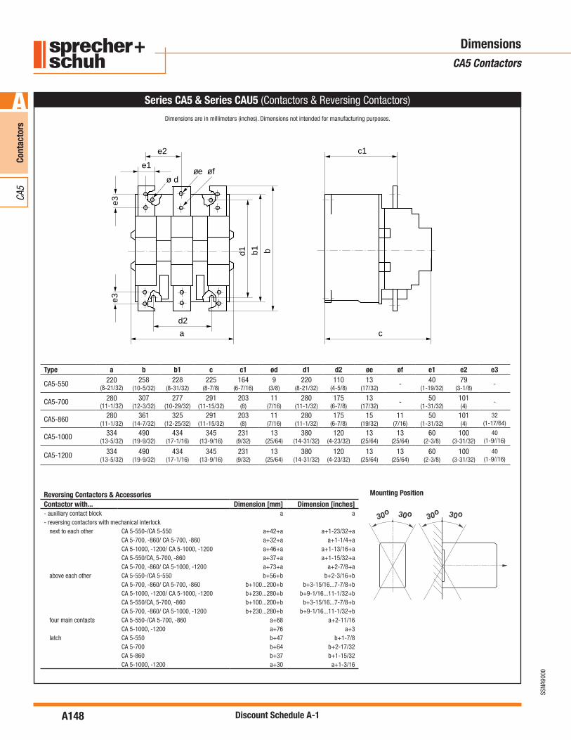
DimensionsCA5 Contactors
Series CA5 & Series CAU5 (Contactors & Reversing Contactors)
d2
a
d1 b1 b
c
e1
e2 c1
øeø d
e3e3
øf
Type a b b1 c c1 ød d1 d2 øe øf e1 e2 e3
CA5-550 220(8-21/32)
258(10-5/32)
228(8-31/32)
225(8-7/8)
164(6-7/16)
9(3/8)
220(8-21/32)
110(4-5/8)
13(17/32)
- 40(1-19/32)
79(3-1/8)
-
CA5-700 280(11-1/32)
307(12-3/32)
277(10-29/32)
291(11-15/32)
203(8)
11(7/16)
280(11-1/32)
175(6-7/8)
13(17/32)
- 50(1-31/32)
101(4)
-
CA5-860 280(11-1/32)
361(14-7/32)
325(12-25/32)
291(11-15/32)
203(8)
11(7/16)
280(11-1/32)
175(6-7/8)
15(19/32)
11(7/16)
50(1-31/32)
101(4)
32(1-17/64)
CA5-1000 334(13-5/32)
490(19-9/32)
434(17-1/16)
345(13-9/16)
231(9/32)
13(25/64)
380(14-31/32)
120(4-23/32)
13(25/64)
13(25/64)
60(2-3/8)
100(3-31/32)
40(1-9//16)
CA5-1200 334(13-5/32)
490(19-9/32)
434(17-1/16)
345(13-9/16)
231(9/32)
13(25/64)
380(14-31/32)
120(4-23/32)
13(25/64)
13(25/64)
60(2-3/8)
100(3-31/32)
40(1-9//16)
Reversing Contactors & AccessoriesContactor with... Dimension [mm] Dimension [inches]- auxiliary contact block a a- reversing contactors with mechanical interlock
next to each other CA 5-550-/CA 5-550 a+42+a a+1-23/32+aCA 5-700, -860/ CA 5-700, -860 a+32+a a+1-1/4+aCA 5-1000, -1200/ CA 5-1000, -1200 a+46+a a+1-13/16+aCA 5-550/CA, 5-700, -860 a+37+a a+1-15/32+aCA 5-700, -860/ CA 5-1000, -1200 a+73+a a+2-7/8+a
above each other CA 5-550-/CA 5-550 b+56+b b+2-3/16+bCA 5-700, -860/ CA 5-700, -860 b+100...200+b b+3-15/16...7-7/8+bCA 5-1000, -1200/ CA 5-1000, -1200 b+230...280+b b+9-1/16...11-1/32+bCA 5-550/CA, 5-700, -860 b+100...200+b b+3-15/16...7-7/8+bCA 5-700, -860/ CA 5-1000, -1200 b+230...280+b b+9-1/16...11-1/32+b
four main contacts CA 5-550-/CA 5-700, -860 a+68 a+2-11/16CA 5-1000, -1200 a+76 a+3
latch CA 5-550 b+47 b+1-7/8CA 5-700 b+64 b+2-17/32CA 5-860 b+37 b+1-15/32CA 5-1000, -1200 a+30 a+1-3/16
Mounting Position
Dimensions are in millimeters (inches). Dimensions not intended for manufacturing purposes.

A149
SSNA
9000
Cont
acto
rs
A
CA5
Discount Schedule A-1
DimensionsCA5 Contactors
Notes


