
Technical handbook - Geotechnics | Building …geotechnicsworld.com/wp-content/uploads/2015/02/Typar...
68
Ask for more eNerGY Typar® l High energy absorption l High initial modulus l High elongation (> 50 %) l Long-term filtration l Outstanding uniformity Elongation % Strength (kN/m) Technical handbook DuPont Tm Typar ® sf GeoTeXTILe
Transcript of Technical handbook - Geotechnics | Building …geotechnicsworld.com/wp-content/uploads/2015/02/Typar...

Ask for more eNerGY
Typar®
l High energy absorptionl High initial modulusl High elongation (> 50 %) l Long-term filtration l Outstanding uniformity
Elongation %
Stre
ngth
(kN
/m)
Tech
nica
l ha
ndbo
ok
DuPontTm Typar® sfGeoTeXTILe

Disclaimer
Further product information is available upon request. This information corresponds to our current knowledge on the subject. It is offered solely to provide possible suggestions for your own testing. It is not intended, however, to substitute for any testing you may need to conduct to determine for yourself the suitability of our products for your particular purposes. This infor-mation may be subject to revision as new knowledge and experience becomes available. Since we cannot anticipate all variations in actual end-use conditions DuPont makes no warranties and assumes no liability in connection with any use of this information. Nothing in this publication is to be considered as a license to operate under or a recommendation to infringe any patent right. Please check independently whether manufacturing and selling of your product may infringe patent rights.
Luxembourg site

1
1
Chapter 1
1.1. Introduction 3
1.2. DuPont Quality 3
1.3. What is DuPontTM Typar® SF? 3
1.4. DuPontTM Typar® fibre production 4
1.5. Typical Characteristics 4
DuPontTM Typar® SF Introduction


1
3
Chapter 1 - DuPontTM Typar® SF introduction
1. DuPontTM Typar® SF introduction
1.1. IntroductionThe purpose of this guide is to provide basic information on geotextiles, their functions and their required properties for different applications. This technical handbook provides guidance on the design, selection and utilisation of DuPontTM Typar® SF geotextiles in civil engineering applications such as the construction of aggregate bases, drainage and erosion control systems. A description of test methods for determining the properties of geotextiles and technical data is given. Details on the DuPont Typar® Geosynthetics product range can be found in our DuPontTM Typar® SF and Typar® HR brochure and on our website www.typargeo.com. For additional advice and technical assistance, please contact the DuPont Geosynthetics Technical Centre.
1.2. DuPont QualityFor two centuries now, DuPont inventions have been leading industry forward with innovative and pioneering high performance materials such Nylon, Kevlar®, Tyvek®, Lycra® and Teflon®. Engineering excellence and quality standards which are second to none: these are just two of the reasons why DuPont Typar® Geosynthetics provide reliable long-term performance for civil engineering and construction projects.
Invented 30 years ago and manufactured at the DuPont Luxembourg site, the high quality and performance of DuPontTM Typar® SF has proven the test of time. With more than 1 billion m2 sold world-wide, DuPontTM Typar® SF geotextiles have been used in roads, railway tracks and construction surfaces equivalent to a six lane motorway of 23 meter width once around the world.
Typar® is manufactured to ISO 9001 standards. The stringent quality requirements of DuPont ensure that only high quality products are released into the market. The integrated production and laboratory system guarantee that the manufacturing process conditions and laboratory results for every roll are traceable.
The environmental management system of DuPont is in accordance with the requirements of the environmental standards of the EMAS (Eco-Management and Audit Scheme) Regulation as well as the ISO 14001. Furthermore DuPontTM Typar® SF geotextiles are CE marked and are submitted to several different certification systems such as the French ASQUAL and the German external audit system “Fremdüberwachung DIN 18200”.
1.3. What is DuPontTM Typar® SF?DuPontTM Typar® SF is a thin, thermally bonded, water permeable nonwoven geotextile made of 100% continuous polypropylene filaments. It is designed to have a combination of a high initial modulus (stiffness), high elongation (typically > 50%) and outstanding uniformity, to give superior performance, to make it resistant to damage and to have excellent filtration properties. DuPontTM Typar® SF is an isotropic material, which means that its physical properties are the same in all directions. This mirrors the stresses and strains of a typical separation application.
Furthermore, the fact that DuPontTM Typar® SF is made of 100% polypropylene, makes it resistant to rotting, moisture and chemical attack, particularly alkalis3.
1 2
1 DQS – Deutsche Gesellschaft zur Zertifizierung von Managementsystemen mbH
2 BVQI – Bureau Veritas Quality International3 details on chemical resistance can be found in the annex section 7.6

4
Chapter 1 - DuPontTM Typar® SF introduction
1.4. DuPont Typar® fibre productionIn the fibre extrusion process, thousands of extremely fine, continuous filaments are produced, which pass through a DuPont patented “pre-stretch” stage. These fine but tough filaments are then laid down (Fig. 1) producing an isotropic fibre web sheet which is then thermally and mechanically bonded.
Figure 1: Filament laydown Figure 2: Typar® microscopic view
By varying the process conditions, a range of high strength Typar® nonwoven structures with different denier and physical properties can be produced. This DuPont patented production technique is one of the main reasons for the unique properties of DuPontTM Typar® SF compared to other geotextiles.
1.5. CaracterísticasThe following figure 3 shows the typical stress-strain behaviour of several geotextiles of similar weight. DuPontTM Typar® SF has a high tensile strength, a high elongation, and also a high initial modulus which is the ideal combination of properties for geosynthetic applications (for comparison see also table 1).
DuPontTM Typar® SF is manufactured to a very high level of uniformity using a continuous on-line, ß-ray and ultrasonic monitoring process. Any product that fails to meet the required standards is rejected and recycled.
In the process stabilisers are added to the polypropylene which increase the durability of DuPontTM Typar® SF. It can endure up to several weeks in direct sunlight, but prolonged exposure, particularly in tropical sunlight, can cause strength losses4. Generally a geotextile should be covered immediately after laying to avoid UV degradation, wind uplifting or mechanical damage.
Figure 3: Typical stress-strain curves of DuPontTM Typar® SF and other geotextiles
DuPontTM
Typar® SF WovenNeedlpunched staple fibre
Needlpunched continuous
Other thermally bonded
Energy high low medium medium very low
Tensile Strength high very high medium high high
Initial Modulus high high very low low high
Elongation high low high high low
Table 1: Stress-strain curves properties of several geotextiles types10-10
10-9
10-8
10-7
10-6
10-5
0 100 200 300 400 500 600 700 800 9000.006
0.005
0.004
0.003
0.002
0.001
0
application area
100
0
-100
-200
-300
-400
-500
-600
180 160 140 120 100 80 60 40 20 2 0 200 220 0m 0.1m 1m 2m 3m 4m 5m 6m 7m 8m 9m 10m 11m
0 15 30 45 60 75 90-15-30-45-60-75-90
Woven Other thermallybonded
Needlepunched (continuous fibres)
Needlepunched
Needlepunched (short fibres)
Needlepunched geotextile
DuPont™ Typar® SF
DuPont™ Typar® SF
DuPont™ Typar® SF
DuPont™ Typar® SF
5 10 15 20 25 30 35 40 45 50
4 Details on UV resistance can be found in the annex section 7.6

5
2
Chapter 2
Functions and requirements
2.1. Introduction 6
2.2. Separation 6
2.3. Stabilisation and reinforcement 7
2.3.1. Restraint and confinement 7
2.3.2. Membrane mechanism 7
2.3.3. Local reinforcement 8
2.4. Filtration 8
2.5. Drainage 9
2.6. Protection 9
2.7. Resistance against damage during installation 9
Energy absorption 10

6
Chapter 2 - Functions and requirements
2.1. IntroductionDepending on the different applications, the main functions of the geotextile are separation, filtration, reinforcement, protection to stabilisation. For most applications a combination of several functions is required. A further requirement is its resistance to damage during installation.
The purpose of this section is to provide a basic, technical understanding of these functions and requirements with respect to geotextiles and to the different mechanisms within each function. It should aid in the selection of the appropriate geotextile for a specific purpose, a difficult task, because the interaction between interrelated factors, such as mechanical and hydraulic properties, clogging, structure, time and degradation etc. is very complex.
2.2. SeparationSeparation is defined as: “The preventing from intermixing of adjacent dissimilar soils and/or fill materials by the use of a geotextile or a geotextile-related product”5 .
The main application areas of a geotextile used as a separator are in road and railway projects. The use of the geotextile preserves and improves the integrity and function of the different materials. Two mechanisms occur when an aggregate base is laid over a soft subsoil and a vertical load is applied.
First of all the geotextile prevents the loss of aggregate into the soft subgrade (Fig. 4). An engineering adage describes this very well: “10 kilos of stone placed on 10 kilos of mud results in 20 kilos of mud”. The geotextile confines the aggregate base and thus a higher degree of compaction can be obtained with subsequent higher bearing capacity.
a2
DuPontTM Typar® SF
a1 > a2
a1
Figure 4: left: Without geotextile - loss of aggregate into soft subgrade, right: With geotextile – no loss of aggregate, better compaction
Secondly the contamination of the aggregate base with soil of the subgrade is prevented and thus the reduction of the bearing capacity avoided. The migration of fine soil particles into the clean aggregate occurs especially under dynamic stress and is called “pumping effect”. These fines act as a lubricant between the coarse aggregate grains and can so substantially reduce the shear strength of the aggregate.
Also, an uncontaminated aggregate will continue to effectively perform in its drainage function as well as maintain a higher resistance to frost heave effects.
2. Functions and requirements
5 EN ISO 10318 Terms and Definitions

7
2
Chapter 2 - Functions and requirements
In its separation function a geotextile can:
l Prevent the reduction of load bearing capacity caused by the mixing of fine-grained subgrade with the aggregate base.
l Increase the bearing capacity by preventing the loss of aggregate into soft subgrade and increasing the degree of compaction.
l Reduce the deterioration of roads through frost heave effects.
l Eradicate the need to remove weak subgrade.
l Maintain the drainage capacity of the aggregate base.
l Prevent migration of fine particles especially under dynamic loads.
2.3. Stabilisation and ReinforcementIn many applications a geotextile fulfills a stabilisation or reinforcement function6. In its stabilisation function the geotextile provides the soil with tensile strength and thus complements the soil’s lack of tensile strength when subject to vertical loads.
There are three distinct mechanisms by which a geotextile can stabilise the aggregate base and improve its resistance to permanent deformation under repetitive loading (see Fig. 5):
Restraint + Confinement Membrane mechanism Local Reinforcement
Figure 5: Three stabilisation mechanisms
The higher the initial modulus of the geotextile the more effective these mechanisms are. Geotextiles with a low initial modulus will have large deformations and provide little restraint, membrane mechanism or local reinforcement. A high initial modulus and high elongation are important to withstand large local deformations and resist puncturing.
2.3.1. Restraint and ConfinementAs indicated in the picture above (Fig. 5), there are two types of restraint. One is related to the reverse curvature of the geotextile outside the wheel path where a downward pressure is created. This has the effect of a surcharge load, which levels out the deformation and enforces the compression of the subsoil. The other is the restraint the geotextile provides when aggregate particles attempt to move away from under the load. The geotextile provides tensile reinforcement to the aggregate layer. This confinement of the aggregate increases its strength and modulus, which in turn decreases the compressive stress on the subgrade by spreading the load better underneath the wheel load.
2.3.2. Membrane MechanismThe membrane mechanism is effective when a geotextile is laid on deformable soil and vertical loads are applied. In-plane tensile stress develops in the geotextile, relieving the soil which is not capable of absorbing it. This in-plane force induces a component of stress perpendicular to the plane of the geotextile sheet, in the direction of the force.
Therefore this is of great significance in temporary road constructions, where it can reduce rutting tremendously. The higher the initial modulus of the geotextile, the higher the possible reduction of ruttingI.
6 For more information and details on the use of geotextiles in reinforced earth structures please refer to the Typar® HR product and design guide. Typical applications for earth reinforced structures are retaining walls, steep slopes, landslide repairs, soft-soil embankments, reinforcement under foundations, reinforcement or bridging over karstic areas or cavities, ... etc.

8
Chapter 2 - Functions and requirements
2.3.3. Local reinforcementLoads on individual stones can cause spot failures in the subgrade. A geotextile with a high initial modulus allows to distribute the load, to reduce the stress and to provide resistance to displacement.
A high elongation avoids the local puncturing of the geotextile because it allows the geotextile to stretch around a penetrating stone.
2.4. FiltrationFiltration is defined as “The restraining of soil or other particles subjected to hydrodynamic forces while allowing the passage of fluids into or across a geotextile or a geotextile-related product”.7
Typically the opening size and the permeability are used to describe the geotextile’s filtration properties. The pore size of an efficient geotextile should be small enough to retain larger soil particles to prevent soil erosion. Small soil particles initially have to pass through the geotextile in order to support the build-up of a bridging network of larger particles which act as a natural soil filter adjacent to the geotextile (Fig. 6). If the pore size of a geotextile is too small, then the small particles cannot be drained away and a small diameter bridging network will be formed. This will produce a natural soil barrier with a lower permeability .
Figure 6: Natural soil filter adjacent to geotextile. Figure 7: Drainage system, soils and geotextile with different permeabilities. Ktot is determined by the least permeable soil layer 10
Efficient geotextile filters must have pores of different shape, size and size distribution similar to the particle size distribution of soil.
It is often ignored that in an aggregate-subbase system (Fig.7) the permeability of the least permeable layer determines the system’s permeability. Usually the soil has a permeability which is significantly lower than that of the geotextile.8
Typical Soil Permeabilities9:
Gravel 3 x 10⁻² m/s Silt 10-9 – 10-7 m/s Sand 10-8 m/sClay 10-8 - 10-10 m/s
The permeability of a geotextile is also influenced by the compressibility of the geotextile. Generally thick geotextiles are susceptible to compression. When installed under pressure, the permeability is reduced. This needs to be taken into account when specifying the required permeability of a geotextile. The thickness itself is rather a descriptive than a design property II.
The filtration function is associated with dam construction, erosion control, road drainage and subsoil drainage. In these constructions the geotextile replaces a conventional granular filter. In an erosion control system of a riverbank or earth slope, coarse material (gabions/riprap) or concrete slabs are commonly used to protect against waterflow or wave action. The erosion of the fine particles is prevented by the use of a geotextile as a filter.
7 EN ISO 103188 except coarse sand and gravel
9 see annex section 7.10 for more details on soil permeabilities10 regarding permeability see also 4.4.2

9
2
Chapter 2 - Functions and requirements
2.5. Drainage Drainage is the collecting and transporting of precipitations, ground waters and/or other fluids. Traditionally, water has been controlled and evacuated using graded natural materials. Over the past 30 years or so, more and more geotextile filters have replaced the aggregate filters to increase the natural drainage capacity of impervious soils.
Figure 8: Composite drainage element Figure 9: Conventional aggregate drainage layer
A geotextile should not be used as a (direct) drainage layer by itself because even though its drainage capacity can be measured in a laboratory using clean water, under realistic site conditions (soil trapped inside the structure) the drainage capacity is unpredictable. It is also important for drainage systems to be capable of maintaining adequate drainage capacity for long term performance even when subjected to high earth pressures. To avoid clogging and contamination of the drainage layer a filter must always be incorporated in a drainage system.
Synthetic drains incorporating a geotextile filter have proved to be a more economic alternative to traditional sand drains, soakaways and other drainage systems. Typically geosynthetic drainage mats or drains are made of a core sandwiched between geotextile filters.(Fig.8).
The filter material is required to show consistent quality and physical properties, outstanding strength and durability, good resistance to installation stresses and long term filtration performance.
The malfunction or premature failure of a drainage system can create serious safety and functional problems with the earth structure concerned. At the very least, a drainage failure will necessitate costly remediation and attendant disruption. It is vital that a filter material is used that can function effectively over the long term even with the most critical soils.
2.6. ProtectionProtection is defined as “The preventing or limiting of local damage to a given element or material by the use of a geotextile or a geotextile-related product”11.
Typically geotextiles are used for protection of geosynthetic barriers in landfill, roofing, tank and water projects.
The most important properties of a geotextile in a protection function are puncture resistance and product uniformity (i.e. no weak spots). Nail puncture resistance tests12 have shown that properties such as thickness and unit weight of the product alone do not provide good protection efficiency.
2.7. Resistance against Damage During InstallationA geotextile will not perform any function if it is destroyed during or immediately after installation. Analyses indicate that the critical period in the life-cycle of a geotextile is during the construction process rather than during the service life. Thus 95% of the damage usually occurs during installation, very often simply the result of impact damage during the off-loading and compaction of aggregates. Usually, if the geotextile survives these installation-related stresses, it will also withstand the in-service stresses.
Considerable work has been undertaken to understand the relationship between the physical properties of a separation geotextile and its actual performance in the field. Test research has confirmed a close correlation between the ability of a geotextile to absorb impact energy and its susceptibility to damage during installationIII.
11 EN ISO 1031812 nail tests simulating on-site behaviour developed by DuPont and performed at DuPont Typar® QC laboratory

10
Chapter 2 - Functions and requirements
The following figures demonstrate the different forms of failure of a geotextile and the importance of a high energy absorption potential:
Figure 10: high elongation allows the Figure 11: high strength allows the geotextile Figure 12: failure of the geotextile due to lack geotextile to stretch around penetrating stone to withstand force from falling stone of strength or lack of elongation
Energy AbsorptionDefinition: Energy is the capacity of a physical system to do work. The standard unit is the joule, symbolised by J. One joule (1 J) is the energy resulting from the equivalent of one Newton (1 N) of force acting over one meter (1 m) of displacement. There are two main forms of energy, called potential energy and kinetic energy. Potential energy, is energy stored in a material.
Figure 13: Comparison of actual and theoretical energy absorption potential
The energy absorption potential (W) of a geotextile can described as the combination of its elongation and its applied strength. It is determined using the stress-strain curve of a geotextile obtained in a tensile strength test. The area under the curve (∫) is the energy absorption potential of the geotextile.
Several national specifications are in the process of adopting the energy absorption concept. Some specifications however are based on theoretical values or energy absorption index rather than calculating the surface under the curve W = ∫ (T * ε) dε. The calculation is simplified to Windex = ½T * ε.
As a result the energy absorption index (Windex) of some products is significantly higher while for others the theoretical energy absorption is lower than the actual energy absorption potential measured during the tensile strength test (EN ISO 10319). The following graph (Fig.13) illustrates this: it shows the different shapes of the actual energy absorption and the theoretical energy absorption potential.
Bibliography
I Love, J.P., Burd, H.J., Milligan, G.W.E. and Houlsby, G.T. (1987). Analytical and model studies of reinforcement of a granular layer on a soft clay subgrade. Canadian Geotechnical Journal, Vol.24, No 4, p. 611-622
II Koerner, Designing with Geotextiles, 4th edition 1998, p.96III SINTEF Report, Arnstein Watn, Non woven geotextiles – Field test on damage during installation, SINTEF Civil and Environmental Engineering, Norway
Evaluation of Installation Damage of Geotextiles - A Correlation to Index Tests, R. Diederich, DuPont de Nemours, Luxembourg

11
3
Aggregates bases
Chapter 3
3.1. Introduction 12
What is the initial modulus? 12
3.2. Functions 12
3.2.1. Stabilisation 12
3.2.2. Separation and Filtration 13
3.2.3. Rutting 13
3. 3. Designing Aggregate Bases with DuPontTM Typar® SF 14
3.3.1. Unpaved Roads 14
3.3.2. Paved Road 17
3.3.3. Paved Roads with Construction Traffic Subbase 18
3.4. Selection of the right DuPontTM Typar® SF style 19
3.4.1. Effect of Traffic 19
3.4.2. Effect of Installation Conditions 20
3.4.3. Effect of Compaction 20
3.4.4. Filter requirements 20
3.5. Installation Guidelines 21
3.6. Design Examples 21
3.6.1. Example 1 (according to 3.3.1) 21
3.6.2. Example 2 (according to 3.3.3) 22
3.6.3. Example 3 24

12
Chapter 3 - Aggregate Bases
3.1. IntroductionThis section is a guideline for the design and construction of aggregate bases for permanent and temporary traffic structures using DuPontTM Typar® SF geotextiles. The technology applies to aggregate bases supporting more or less dynamic loads in runways, roads and highways, temporary construction/access roads, storage areas, parking lots and sports facilities.
For paved surfaces, such as roads, highways and runways, design methods have been developed by National Road Administrations based on local conditions and wide experience. Therefore it is not the intention of this guide to propose new design methods but simply to emphasise the benefits of using DuPontTM Typar® SF in such paved structures. However, the design procedures presented hereafter might be applied to paved structures, by considering that the subbase is to be used as a temporary construction road during the construction period.
This design procedure for using DuPontTM Typar® SF is the result of knowledge gained from several full-scale road tests built over various subgrades of low bearing capacity and of over 30 years experience.
Strength [kN/m]
T = X
ε = 10% Elongation [%]
Figure 14: Initial modulus = Secant modulus at e.g. e = 10%
3.2. FunctionsThe combination of functions of a geotextile to provide additional strength to the aggregate base (compared to an equal thickness of aggregate over a subgrade without DuPontTM Typar® SF) is different for every application. For aggregate bases the main functions are separation and stabilisation. Studies have shown that stabilisation functions depend largely on the modulus of the fabricI. Furthermore the aggregate layer thickness can be reduced significantly by using a geotextile.
3.2.1. StabilisationThe effectiveness of the mechanisms described in the previous chapter are all related to the stress-strain behaviour of the geotextile (see Fig. 15). Different types of geotextiles have a different stress-strain curve. This difference can best be described as the energy absorption potential W (see also section 2.7).
Woven geotextiles have a very high initial modulus and high maximum strength but a low elongation which results in a low energy W. Needlepunched nonwovens have a low initial modulus, and a large deformation is needed before a noticeable tensile strength is developed in the geotextile; this results in low energy absorption potential W. DuPontTM Typar® SF has a high initial modulus, high strength and a high elongation at maximum load, and therefore has a high energy absorption potential W. As a high energy absorption gives high damage resistance DuPontTM Typar® SF is particularly suitable for stabilisation.
3. Aggregate bases
What is the initial modulus?The initial modulus describes the behaviour of a geotextile at low deformation. Using the secant modulus at, for example, 5% strain gives a clear indication. A line is drawn from the axes’ origin to the designated curve at 5% strain (Fig. 14). The initial modulus (slope) is measured K = T/ε The steeper the gradient the higher the modulus.
The higher the tensile strength of a geotextile at an initial deformation, e.g. 5%, the higher the initial modulus, the higher the resistance to rutting!

13
3
Chapter 3 - Aggregate Bases
Figura 15: Curvas convencionales de tensión-deformación de diferentes geotextiles.
3.2.2. Separation and FiltrationThe hydraulic requirements such as an adequate range of pore sizes to perform an efficient filtration function are provided by the range of opening sizes of DuPontTM Typar® SF, which are similar to that of soil. The water permeability of DuPontTM Typar® SF is generally higher than that of most subsoils13. Furthermore the water permeability of DuPontTM Typar® SF is unaffected by load compression as it has a precompressed structure in contrast to thicker compressible geotextiles.
3.2.3. RuttingRutting can become a serious problem, especially for temporary roads. The regular passage of wheeled transport results into tension stresses that deform the subsoil. Different from most other geotextiles, DuPontTM Typar® SF needs much lower elongation and deformation to take up stresses (high initial modulus) and will therefore considerably reduce rutting. In the graph below (Fig. 16) the results of tests simulating a traffic load II by submitting various geotextiles to 1000 dynamic loading cycles show the difference between DuPontTM Typar® SF and two needlepunched geotextile products (NP staple fibres, NP continuous fibres) with a low initial modulus.
The results indicate a correlation between initial modulus and deformation (rutting). The high initial modulus enables DuPontTM Typar® SF to absorb more external stress before transferring this energy absorption to strain.
Due to its high energy absorption DuPontTM Typar® SF has a very good resistance to damage during installation. Furthermore sufficient elongation at break is necessary to withstand local penetration by stones and to provide a good safety margin once the geotextile is under stress.
Location (cm)
Dis
plac
emen
t (m
m)
Figure 16: Estimated deflection bowls after 1000 cycles - deflection measured at the geotextile level - Class 3 products14
13 with the exception of coarse sands and gravel14 according to the Norwegian Classification System

14
Chapter 3 - Aggregate Bases
3.3. Designing Aggregate Bases with DuPontTM Typar® SF
The main causes of pavement degradation are:
l The contamination of the aggregate base by a fine-grained subgrade under dynamic loading (“pumping effect”) that causes a substantial reduction of the shear resistance of the aggregate. The thickness of the “clean” aggregate and therefore the bearing capacity of the structure is reduced down to unacceptable levels
l Contamination of the aggregate base as described above which will make the aggregate sensitive to frost, with subsequent reduction of bearing capacity during thaw periods
l Lack of subsurface drainage
l Unpredicted traffic increase
The use of DuPontTM Typar® SF will prevent aggregate contamination and therefore results in an increased service life.
This guide uses the CBR15 value as a measure of soil strength. The correlation factors between CBR, Cu (undrained shear strength), Ev (rigidity modulus) and ME (compressibility modulus) are given in the following table 2. The design properties presented here for unpaved and paved roads are based on a standard DuPontTM Typar® SF style with an energy level 2. Depending on the installation and traffic conditions a geotextile with a higher energy level may be chosen.
Correlation chart for Estimating the subgrade CBR value:
0,5
20
2 2 4 6 8 10 12 14
14 12 10 8 6 4 2
16 18 6 10 14 18 22 26 30 34 38 42
40 60 80 100 120 140 160 180 200 220 240 260 280
1 1,5 2 2,5 3 4 5 6 7 8 9
Soil
* Undrained shear strength ** Compressibility Modulus
CBR
Cu [kN/m2]*
Cu [psi]
ME [MN/m2]**
EV [MN/m2]
Very poor Poor Fair Medium Good
Table 2: Correlation chart for estimating the subgrade CBR value (ref. Barenberg)
3.3.1. Unpaved RoadsAn unpaved road that gives temporary or permanent access (i.e. construction or gravel road) normally consists of a simple, unbound aggregate base.
The proposed design method below assumes that the installation of DuPontTM Typar® SF between subgrade and aggregate base allows for:
l Better aggregate compaction
l Subgrade consolidation under dynamic loads
l Reinforcement of the structure by membrane and restraint effect
l Admissible pressure on subgrade increased to the ultimate bearing capacity p= (π + 2)* Cu
The combination of these benefits is equivalent to an increase of the subgrade CBR by approximately 3 percent points based on empirical data. This design method can only be applied to designs using DuPontTM Typar® SF.
The procedure is first to determine the initial aggregate thickness according to load and subgrade conditions, and then consider the service life and aggregate efficiency. After specifying the effective aggregate thickness Teff a style of DuPontTM Typar® SF with the suitable energy level needs to be chosen.
A. Initial Aggregate Thickness T0
B. Adjustment of T0 for Service Life ⇒ T
C. Adjustment of T for Aggregate Efficiency ⇒ Teff
18 Índice de capacidad de carga californiano (capacidad de carga del suelo); los métodos de aproximación al terreno se pueden consultar en el anexo 7.10.

15
3
Chapter 3 - Aggregate Bases
Attention needs to be paid to axle loads > 130 kN. The appropriate curve for the determination of the initial aggregate thickness T0 needs to be chosen and the actual number of passes N is used to determine the service life adjustment factor C.
Design Method Unpaved Road
A. Initial Aggregate Thickness T0
Soil bearing capacity CBR, Cu
Axle Load Pi
Enter Figure 17 using the subgrade CBR and axle load Pi 16 to determine T0, the compacted crushed stone thickness
for 1000 axle loads. Alternatively, Table 3 lists the formula to calculate T0.
CBR [%] P1 [kN] P2 [lbs]
0,51
1.52345678910
45.3132.3725.8922.4720.5618.6617.1416.0014.8513.7112.9512.19
0.1190.0850.0680.0590.0540.0490.0450.0420.0390.0360.0340.032
T0 (mm) = P1 Axle Load (kN)
T0 (in) = P2 Axle Load (lbs)
Figure 17: Unpaved roads: Compacted crushed stone Table 3: Factors to determine curve Pi thickness for 1000 axle loads.
B. Adjustment of To for service life
Axle Load Pi
Actual number of passes Ni
Compacted crushed stone thickness T0
T = C * T0 = T = (0.27 * log(Σ Ni * ESAL) + 0.19) * T0
l If the most frequent axle loads are heavier than 130 kN (e.g. quarry haul roads), the use of the Ne=Σ Ni*ESAL (Number of Equivalent Axle Loads) is not appropriate. The service life adjustment factor C must be determined using the actual number of passes Ni
l The service life is expressed as the total number of 80 kN axle load application. The actual axle load is first converted to an equivalent standard axle load (P0= 80 kN) using the equivalence factor ESAL:
ESAL= (Pi/P0)3.95
16 an axle load is usually determined by dividing the gross weight of the vehicle by the number of axles, unless the actual axle loads are known. Each axle load can be converted to an equivalent standard axle load Po = 80 kN using the equivalence factor ESAL.

16
Chapter 3 - Aggregate Bases
Axle load (kN)
ESAL Axle load (kN)
ESAL
10 0.0003 140 9,1220 0,004 150 11,9830 0,021 160 15,4540 0,065 170 19,6450 0,16 180 24,6160 0,32 190 30,4770 0,55 200 37,3180 1,0 250 90,0890 1,59 300 185,10100 2,41 400 576,70110 3,52 500 1392,30120 4,96 600 2860,80130 6,80 700 5259,30
Table 4: Equivalence factor (ESAL)
Figure 18: Adjustment factor for service lifeIII
l Then the aggregate thickness T becomes:
T = C * T0 = (0.27 * log(Σ Ne) + 0.19) * T0
C. Adjustment of T for aggregate efficiency
Teff = Σ Ti / αi
The different materials used for aggregate bases are more or less effective. This difference is accounted for by using the aggregate efficiency factor α. The chosen aggregate should be compactible.The idea is to lock the whole mass together under load in order to take advantage of the reinforcement mechanisms of DuPontTM Typar® SF. Angular crushed aggregate is the best because it interlocks well and provides a high bearing capacity. Depending on availability, other materials or blends can be used. Table 5 indicates typical thickness efficiency factors a of various surfacing and base materials.
Table 4 lists the equivalence factor ESAL for different axle loads.
l By multiplying the actual number of axle passes (Ni) with ESAL, NE the number of passes of equivalent standard axle loads is determined
NE = Σ Ni * ESALi
Since T0 is indexed to a service life of 1000 axle load application, it must be adjusted by a factor C that depends on the actual number of standard loads NE.The relationship between NE and C is shown in Fig. 18.
17
3
Chapter 3 - Aggregate Bases
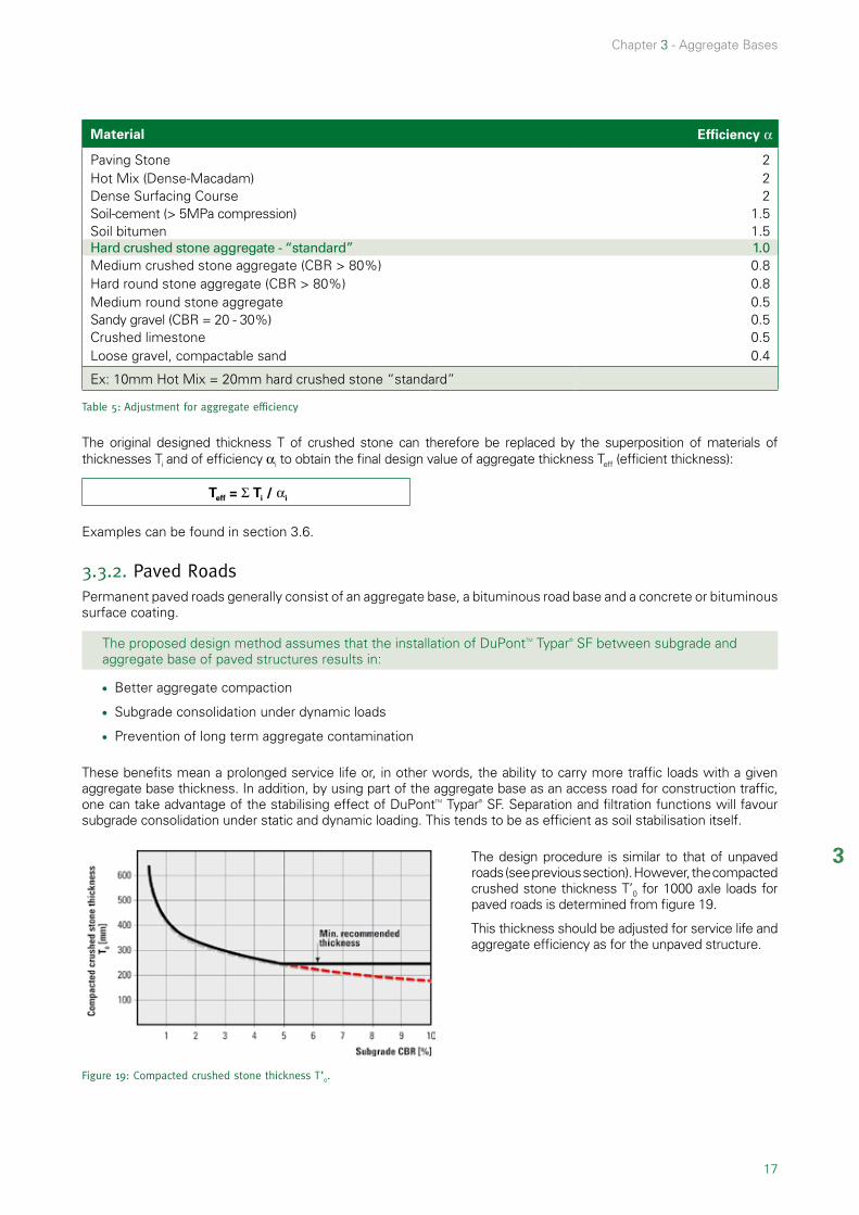
Material Efficiency α
Paving Stone 2Hot Mix (Dense-Macadam) 2Dense Surfacing Course 2Soil-cement (> 5MPa compression) 1.5Soil bitumen 1.5Hard crushed stone aggregate - “standard” 1.0Medium crushed stone aggregate (CBR > 80%) 0.8Hard round stone aggregate (CBR > 80%) 0.8Medium round stone aggregate 0.5Sandy gravel (CBR = 20 - 30%) 0.5Crushed limestone 0.5Loose gravel, compactable sand 0.4
Ex: 10mm Hot Mix = 20mm hard crushed stone “standard”
Table 5: Adjustment for aggregate efficiency
The original designed thickness T of crushed stone can therefore be replaced by the superposition of materials of thicknesses Ti and of efficiency αi to obtain the final design value of aggregate thickness Teff (efficient thickness):
Teff = Σ Ti / αi
Examples can be found in section 3.6.
3.3.2. Paved RoadsPermanent paved roads generally consist of an aggregate base, a bituminous road base and a concrete or bituminous surface coating.
The proposed design method assumes that the installation of DuPontTM Typar® SF between subgrade and aggregate base of paved structures results in:
l Better aggregate compaction
l Subgrade consolidation under dynamic loads
l Prevention of long term aggregate contamination
These benefits mean a prolonged service life or, in other words, the ability to carry more traffic loads with a given aggregate base thickness. In addition, by using part of the aggregate base as an access road for construction traffic, one can take advantage of the stabilising effect of DuPontTM Typar® SF. Separation and filtration functions will favour subgrade consolidation under static and dynamic loading. This tends to be as efficient as soil stabilisation itself.
Figure 19: Compacted crushed stone thickness T’0.
The design procedure is similar to that of unpaved roads (see previous section). However, the compacted crushed stone thickness T’0 for 1000 axle loads for paved roads is determined from figure 19.
This thickness should be adjusted for service life and aggregate efficiency as for the unpaved structure.
18
Chapter 3 - Aggregate Bases
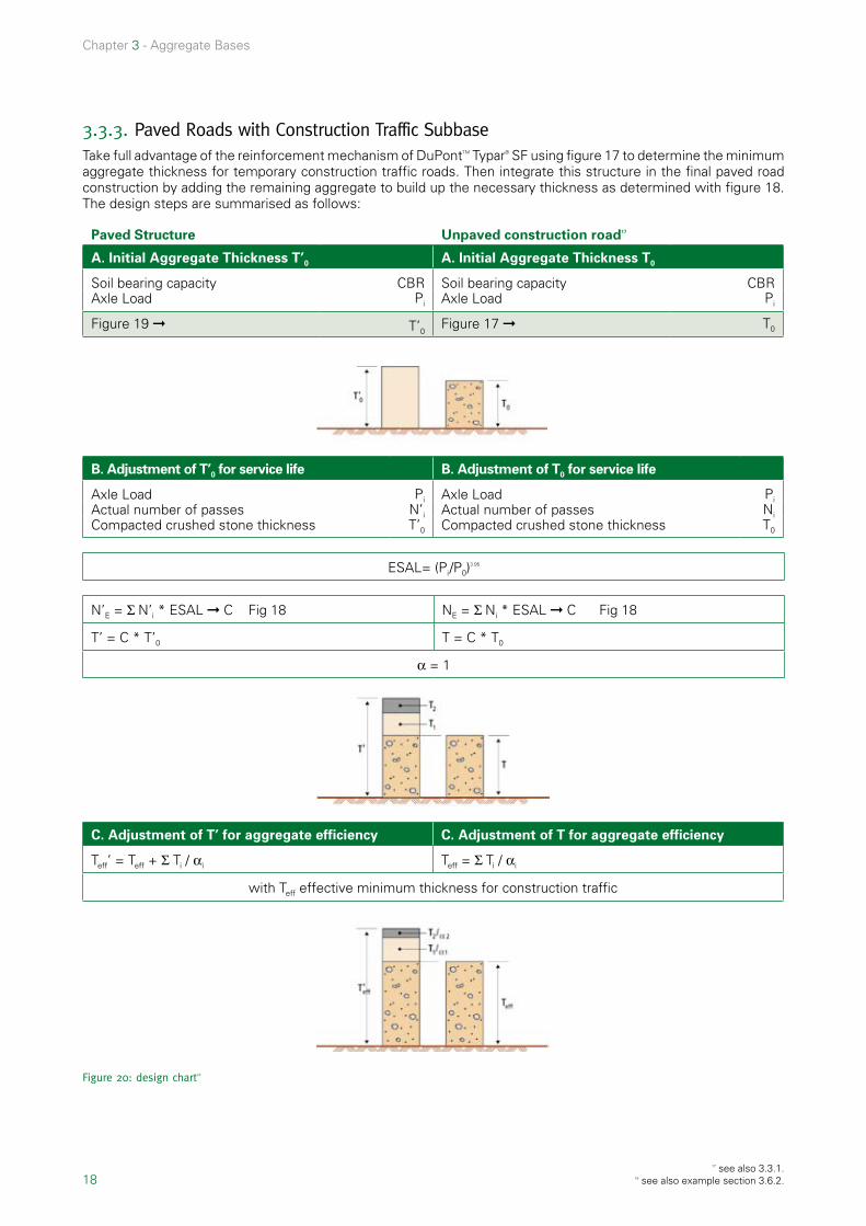
3.3.3. Paved Roads with Construction Traffic SubbaseTake full advantage of the reinforcement mechanism of DuPontTM Typar® SF using figure 17 to determine the minimum aggregate thickness for temporary construction traffic roads. Then integrate this structure in the final paved road construction by adding the remaining aggregate to build up the necessary thickness as determined with figure 18. The design steps are summarised as follows:
Paved Structure Unpaved construction road17
A. Initial Aggregate Thickness T’0 A. Initial Aggregate Thickness T0
Soil bearing capacity CBR Soil bearing capacity CBRAxle Load Pi Axle Load Pi
Figure 19 ➞ T’0Figure 17 ➞ T0
B. Adjustment of T’0 for service life B. Adjustment of T0 for service life
Axle Load Pi Axle Load Pi
Actual number of passes N’i Actual number of passes Ni Compacted crushed stone thickness T’0 Compacted crushed stone thickness T0
ESAL= (Pi/P0)3.95
N’E = Σ N’i * ESAL ➞ C Fig 18 NE = Σ Ni * ESAL ➞ C Fig 18
T’ = C * T’0 T = C * T0
α = 1
C. Adjustment of T’ for aggregate efficiency C. Adjustment of T for aggregate efficiency
Teff’ = Teff + Σ Ti / αi Teff = Σ Ti / αi
with Teff effective minimum thickness for construction traffic
Figure 20: design chart18
17 see also 3.3.1. 18 see also example section 3.6.2.

19
3
Chapter 3 - Aggregate Bases
3.4. Selection of the right DuPontTM Typar® SF style
The design guidelines presented in the previous section are based on a standard DuPontTM Typar® SF energy level 1. Higher performing energy level 2, 3 or 4 may be used in case of additional design requirements to withstand the:
l Effect of Traffic
l Effect of Installation Conditions
l Effect of Compaction
Determine the required level according to figure 21 to 23 and select the equivalent energy level of DuPontTM Typar® SF from table 6 below.
Energy Level Level 1 Level 2 Level 3 Level 4
Test Standard Unit
Energy Absorption (actual)
EN ISO 10319/ ASTM D4595
kJ/m2 2,5 5 8 11
Tensile Strength kN/m 7 12 20 25
Elongation % 45 50 50 50
Strength at 5% Elongation kN/m 3 5 8 10
Puncture CBR EN ISO 12236 N 1000 1500 2500 3500
Cone Penetration EN 918 mm 35 30 25 20
minimum recommended DuPontTM Typar® SF SF 32 SF 49 SF 77 SF 94
Table 6: Minimum values for different Typar® SF energy levels19
3.4.1. Effect of Traffic
Higher fabric properties are required to withstand:
l Fatigue caused by large number of equivalent standard axle loads (ESAL)
l Additional stresses caused by heavy duty equipment (generally with axle loads larger than 130 kN). The correct DuPontTM Typar® SF energy level can be selected using figure 21 according to subgrade CBR and the number of axle load applications.
Figure 21: Recommended energy levels as a function of traffic 20
19 Please note that the selection of Typar® energy levels may depend on national classification systems and specifications.
20 NE = ∑ Ni * ESALi.

20
Chapter 3 - Aggregate Bases
3.4.2. Effect of Installation Conditions To fulfill its long-term functions, the geotextile should withstand installation stresses, particularly aggregate dumping and compaction. Figure 22 indicates the recommended DuPontTM Typar® SF energy level as a function of aggregate size and drop height. It is evident that aggregate backdump and push-ahead over an existing layer instead of dumping directly on the geotextile allows the use of styles with a lower energy level.
Figure 22: Recommended energy level as a function of aggregate size and drop height
3.4.3. Effect of CompactionPuncture by sharp stones during aggregate compaction is detrimental to the long term separation function. Figure 23 indicates the recommended DuPontTM Typar® SF energy levels as a function of soil CBR and D90 (90% passing size) of the crushed aggregate in contact with DuPontTM Typar® SF.
Remark: Styles with a lower energy than 2 kJ/m2 may be used if there is light traffic (cars) only and maximum aggregate size does not exceed 50mm.
Figure 23: Recommended energy level as a function of «crushed stone» size and subgrade CBR
3.4.4. Filter requirementsTo perform efficient long term separation and filtration functions, the geotextile should meet simplified criteria of table 7 in which the O90 is measured by wet sieving test method (EN 12956).
very fine, cohesive soils non cohesive soils
D85 < 0.06, D10 < 0.002
O90 ≤ 0.200mm O90 ≤ 2 * D85
Table 7: General filter requirements.

21
3
Chapter 3 - Aggregate Bases
3.5. Installation Guidelines
The following measures should be followed when installing DuPontTM Typar® SF in road constructions and aggregate bases:
l 1) Remove all large debris which might puncture DuPontTM Typar® SF
l 2) DuPontTM Typar® SF should be at least as wide as the base of the aggregate layers
l 3) When using two or more rolls, ensure sufficient overlap (usually min.30cm)
l 4) If it is windy, use shovelfuls of coarse aggregate at regular intervals to hold DuPontTM Typar® SF in place
l 5) Backdump aggregate without driving directly on the geotextile (Fig. 24)
Figure 24: Backdumping aggregate on DuPontTM Typar® SF without driving on it
l 6) Level and compact aggregate before any heavy traffic occurs
l 7) Avoid aggregate size in excess of 1/3 of the aggregate layer thickness
l 8) Fill up ruts, if any, as soon as they exceed 1/3 of the aggregate layer thickness. Rutting will then be stopped.
l 9) First aggregate layers must be at least 250mm thick
3.6. Design Examples
3.6.1. Example 1 (according to 3.3.1)A contractor desires all-weather access to a remote bridge construction site over an organic clay with a CBR of 2.5%. About 6 trucks (3 axles) will enter the site daily over a period of 5 months.
A source of inexpensive gravel is close (α = 0.4 , Dmax = 100mm).
A. Initial aggregate thickness T0
Soil bearing capacity
Axle Load
Figure 17 ➞
CBR = 2.5
Pi = 80 kN
T0 = 190 mm
B. Adjustment of T0 for service life
Axle Load
Actual number of passes
Compacted crushed stone thickness
Pi = 80 kN
Ni = 6 trucks/day
T0 = 190 mm

22
Chapter 3 - Aggregate Bases
ESAL= (Pi/P0)3.95 = 1
NE = Σ Ni * ESALi
NE = 5 months * 30 days/mont * 6 trucks/day * 3 axles * 1 = 2700
Fig 18 ➞ C = 1.12
T = C * T0 = 1.12 * 190 = 212 mm
C. Adjustment of T for aggregate efficiency
Teff = Σ Ti / αi = 212/0.4 = 530 mm
Selection of the suitable DuPontTM Typar® SF energy level
CBR = 2.5% NE = 2700 Fig 21 : ➞ level 1
Drop height = 1 m Dmáx = 100 mm Fig 22 : ➞ level 1
Fig 23 : only applicable to crushed aggregateTable 7: cohesive soil Omáx ≤ 0.200 mm
➞ SF 37
Installation: follow the installation guidelines see 3.5 install two layers of gravel each 330mm and compact to 265mm
3.6.2. Example 2 (according to 3.3.3)A transport company will build a terminal and parking area with an expected life time of fifteen years. 20 trucks per day will use the facility and 8 of these will be empty one way. The trucks have 4 loaded axles.
The site is in low area and on uneven ground. A CBR of 1% was obtained during a site investigation. The access road and parking area will be paved with a 70mm (= Thotmix) surfacing course of hot mix. A sandy gravel will be used for the base of the construction traffic road (α = 0.5) and then topped off by a good quality round stone aggregate (α = 0.8 , Dmax = 100mm) for the final structure.
Initially the contractor will create a stable working and assembly area to and around the terminal. This aggregate structure will be incorporated in the final paved structure which will save time and money.
Following figure 20 design chart:
Paved Structure Unpaved construction road
A. Initial aggregate thickness T’0 A. Initial aggregate thickness T0
Soil bearing capacity CBR = 1% Soil bearing capacity CBR = 1%Axle Load Pi = 80 kN Axle Load Pi = 80 kN
Figure 19 T’0 = 420 mm Figure 17 T0 = 280 mm
B. Adjustment of T’0 for service life B. Adjustment of T0 for service life
Axle Load Pfull = 80 kN Pempty = 30 kN
Axle Load Pi
Actual number of passes N’i Actual number of passes Ni
Compacted crushed stone thickness T’0
Compacted crushed stone thickness T0
ESALfull = (Pi/P0)3.95 = 1
ESALfull = (30/80)3.95 = 0.021 ESALconstruction estimate = 3000

23
3
Chapter 3 - Aggregate Bases
N’full = 32 x 6 x 52 x 15 x 4 axles = 599040
NE construction estimate = 3000N’empty = 8 x 6 x 52 x 15 x 4 ejes = 149760
N’E = 599040 x 1 + 149760 x 0.021 = 602185
Fig 18 ➞ C = 1.75 Fig 18 ➞ C = 1.13
T’ = C * T’0 = 1.75 * 420 ≅ 740 mm T = C * T0 = 1.13 x 280 ≅ 320 mm
α = 1
C. Adjustment of T’ for aggregate efficiency C. Adjustment of T for aggregate efficiency
Teff’ = Teff + Σ Ti / αi Teff = Σ Ti / αi
with Teff effective minimum thickness for construction traffic
Of the total thickness T’ of 740mm, 320mm (α=1) were used to support the construction traffic. 70 mm of wearing course are equivalent to 140mm of a material with an efficiency of α=1. The remaining 280mm (Trem) can be provided by 350mm (= 280/0.8) of round stone aggregate. This results in a effective minimum thickness of 790mm.
T’eff = Teff + Thotmix /α hotmix + Trem /α remTeff = 320/ 0.5 = 640 mm
Trem = T’ - T - Thotmix (α=1) = 740 - 320 – 140 = 280 mmT’eff = 640 + 140/2 + 280/0.8 = 1060 mm
Note: T’eff is the thickness of the unpaved construction road.Thotmix is the thickness of the wearing course.Trem is the additional thickness necessary to fulfill thickness requirements for permanent paved road.
Selection of the suitable DuPontTM Typar® SF energy level
CBR = 1.0 % N’E = 602185 Fig 21 : ➝ level 2
Drop height = 1 m Dmáx = 100 mm Fig 22 : ➝ level 1
Fig 23 : only applicable to crushed aggregate
➞ SF 49
Installation
l Follow the installation guidelines (section 3.5)
l Install 640mm of round stone aggregate for construction traffic in two layers
l Install 350mm of round stone aggregate and 70mm hot mix wearing coarse

24
Chapter 3 - Aggregate Bases
3.6.3. Example 3A contractor wants to suggest a refined road design to the road authority in order to show possible savings by using a geotextile. The original design presented by the road authority to tender for is as follows:
Road structure:
This design is based on the following estimates for traffic:
l Traffic: axle load is 8 tons or 80 kN 10 years design life total of 15*106 axle loads / lifetime of the road
l Bearing Capacity: existing roadbed CBR 1 – 5%
As the CBR of the existing roadbed varies a new road structure is determined for the CBR = 1%, 3% and 5%. Furthermore layers 1, 2, 3 will remain unchanged with the current design thickness of T’eff1-3 = 250mm and an equivalent thickness T1-3, α =1 = (T1+T2) * α1,2 + T3 * α3 = 430mm using the aggregate efficiency factors α1,2 = 2 and α3 = 1.5. The equivalent thickness for layer 4 is 150/ (α = 1) = 150mm, for layer 5 the thickness is 300/ (α=0.5) = 600mm. All of the following comparisons are based on an aggregate efficiency of α=1.
The equivalent road structure is outlined below:
A. Initial Aggregate Thickness T0
Soil bearing capacity CBR = see table belowAxle Load Pi = 80 kNFigure 17 ➞ T’0 = see table below
CBR 1% 3% 5%
T0’ (thickness) (Fig. 8) [mm] 420 300 250

25
3
Chapter 3 - Aggregate Bases
B. Adjustment of To for service life
Axle Load Pi = 80 kNNumber of passes (ESAL) N’E = 15 * 106 axle loadsCompacted crushed stone thickness T’0 = see table above
CBR 1% 3% 5%
C (service life adjustment) 2.1 2.1 2.1
T = T0’ * C (mín. with α=1) [mm] 880 630 525
C. Adjustment of T for aggregate efficiency
CBR 1% 3% 5%
Tremain (= T – T1-3,a=1) [mm] 450 200 95
The remaining thickness Tremain can be divided between the two available materials in the following way :
T4 (standard aggregate) [mm] 150 100 -
T5 (sand/gravel mix) [mm] 300 100 95
Reduction (= T – 730 mm ) [mm] +150 -100 -205
This leads to savings in the effective thickness for CBR = 3% and 5% and to an augmentation of thickness for CBR = 1%.
CBR 1% 3% 5%
T4,eff (standard aggregate) [mm] 150 100 -
T5,eff (sand/gravel mix) [mm] 600 200 190
eff reduction (=Tdesign - Teff ) [mm] +300 -150 -260

26
Chapter 3 - Aggregate Bases
BibliographyI Robnett, Q.L. and Lai, J.S., Fabric Reinforced Aggregate Roads – An Overview., 61st Annual Meeting of TRB in Washington, January, 1982 Lavin, J.G., Murray, C.D., Murch, L.E., Robnett, Q.L. and Lai, J.S., Prospects of spunbonded Fabrics in Civil Engineering, Proceedings of Nonwoven Fabrics Conference, University of Manchester, Institute of Science & Technology, June, 1980 Robnett, Q.L., Lai, J.S., et al, Use of Geotextiles in Road Construction: Laboratory Study, Proceedings of First Canadian Symposium in Geotextiles, Calgary, Alberta, Canada Robnett, Q.L., Lai, J.S., et al, Use of Geotextiles in Road Construction, Proceedings, Third Conference – Road Engineering Association of Asia and Australia, Taipei, April, 1981
Robnett, Q.L., Lai, J.S., et al, Use of Geotextiles to Extend Aggregate Resources, ASTM Symposiumon Extending Aggregate Resources, December 1980 Giroud, J.P., Noiray, L., Geotextile Reinforced Unpaved Road Design, Journal of the Geotechnical Division, ASCE, Volume 107, GT9, September, 1981II SINTEF Report, Non-woven Geotextiles in Road Constructions, 1996III Hammit II.G.M., “Thickness Requirements for unsurfaced Roads and
Airfields Bare Base Support”. Technical report s. 70 – 5, July 1970. US Army Engineer Waterway Experiment Station, Vicksburg M.S.

27
4
4.1. Introduction 28
4.2. Functions 28
4.3. Geotextile properties 29
4.4. Designing Drainage Systems 29
4.4.1. Soil retention criterion 30
4.4.2. Permeability criterion 31
4.4.3. Special soils 32
4.4.4. Comments and additional selection criteria 32
4.5. Typical drainage systems 33
4.5.1. French Drains 33
4.5.2. Shoulder Drain 33
4.5.3. Area Drainage 34
4.5.4. Blanket Drains 34
4.5.5. Composite Drainage 35
4.6. Installation guidelines 36
4.6.1. Trenches 36
4.6.2. Blanket drains 36
4.6.3. Vertical drains with DuPontTM Typar® SF 37
Drainage systems
Chapter 4

28
Chapter 4 - Drainage systems
4.1. IntroductionThis section is a guideline for the use of DuPontTM Typar® SF as a filter medium, the basic design and the construction of some typical drainage systems. The design procedure for using DuPontTM Typar® SF is the result of knowledge gained from several laboratories and field tests, as well as the experience gained from thousands of installations throughout the world.
4.2. FunctionsIn drainage applications (controlled discharge of water) it has become standard practice to replace the conventional granular filter with a geotextile filter. A geotextile filter fulfills the same function: it prevents the clogging of the drain but with the advantage of easy installation and a controlled filter quality that is not compromised by poor construction conditions. The use of geotextiles leads to substantial cost savings thanks to shorter installation times, reduced excavation and reduced material use.
The properties of a geotextile are significantly influenced by its structure. Woven tape geo-textiles usually have a low percentage open area. As the limited number of pores generally have the same diameter they are subject to blocking or blinding by soil particles. Thick geotextiles have a long and tortuous flow path, the small soil particles can be easily trapped in the narrow channels. This partial clogging and their sensitivity to compression can cause significant reduction of permeability.
DuPontTM Typar® SF, on the other hand, has a superior soil particle retention and water permeability properties. It has a good soil particle retention because of its wide range of pore sizes and shapes. The soil particles are unlikely to be trapped in DuPontTM Typar® SF because of its thin precompressed structure, which is also the reason for its hydraulic property’s insensitivity to compression.
Additionally the geotextile needs to withstand the installation stress to be able to perform its filtration function properly. Due to its high initial modulus and high elongation DuPontTM Typar® SF has a high energy absorption potential which makes it very resistant to damage during installation as well as providing dimensional stability for pore size and permeability.
Figure 6’: Natural soil filter adjacent to geotextile
And how does DuPontTM Typar® SF work? DuPontTM Typar® SF permits the build-up of a natural soil filter adjacent to the geotextile after being installed. This resulting bridging network will only develop if the geotextile has an adequate pore size distribution (Fig.6’). The following guidelines will help you make the right filter selection.
4. Drainage systems

29
4
Chapter 4 - Drainage systems
4.3. Geotextile properties Extensive research programmes have been run world-wide to define the filtration performance of geotextiles by correlating the particle size distribution of the soil-to-be-filtered and the hydraulic conditions to the pore size distribution and water permeability of the geotextile.
The most important properties of a geotextile filter are the pore size and the permeability. The characteristic pore size can be read from the pore size distribution of a geotextile. This distribution is determined by using either a soil with a defined particle size distrubution (EN 12956) or glass beads of defined sizes (ASTM D4751). The result is the opening size O90 or O95, which describe the opening size through which 90/95 % of the soil/glass beads passed. A more detailed description of the test mehods can be found in chapter 7.1.3.
Choosing the right opening size is vital for the functioning of a filtration system. It assures the build-up of a natural soil filter on top of the geotextile. The wrong opening size can result in continuous piping and soil erosion or even reduction of permeability.
The permeability of a geotextile can be defined by the permeability coefficient k . It describes the flow of water perpendicular to the plane of the soil or geotextile. The permeability coefficient k of a geotextile can be useful when comparing to the permeability of the geotextile to that of a soil. To evaluate the suitability of geotextiles with different structures it is best to compare the permeability under load. The following figure 25 shows how the permeability of a thick, compressible nonwoven geotextile changes under pressure compared to a precompressed DuPontTM Typar® SF.
Figure 25: Permeability under pressure – Comparison of Needlepunched with DuPontTM Typar® SF
Another way to describe the permeability of a geotextile is the hydraulic conductivity or flow rate [l/(m²*s)] at a given water head, for example VH50 according to EN 11058. The most important aspect is to select a geotextile with a permeability that is higher than that of the soil to be filtered. This is necessary to allow the natural flow of water.
4.4. Designing Drainage Systems
The selection of the right filter is a complex process because a number of factors govern the interaction between soil and filter:
l Geotextile properties: pore size distribution (O90), water permeability, compressibility, and structure
l Soil conditions: particle size distribution, uniformity coefficient, compaction, plasticity, and cohesion
l Hydraulic conditions: unidirectional or reversible flow, gradient, and chemical precipitation
l Installation conditions: physical damage during installation, and soil water content during installation
The two main criteria to be considered when designing for a filter application are soil retention and permeability.

30
Chapter 4 - Drainage systems
4.4.1. Soil retention criterion The selection starts with determining the soil particle distribution of the soil to be filtered. The limits for the maximum opening size O90 can be determined. The general criteria for non-critical situations (steady flow, low gradient) is:
O90 < 2 * D85
For applications where limitation of piping is the predominant factor the following criteria are to be applied:
Very fine, cohesive soils
D85 < 0.06 and D10 < 0.002
Fine, non-cohesive soils
D40 < 0.06
Coarse soils
D40 > 0.06
steady flow O90 < 0.200 O90 < 6 * D60 O90 < 5 * D10 √Cu 21
dynamic flow laboratory test required22 O90 < 1,5 * D10 √Cu
O90 < D60
Table 8: Filter criteria for different soils and flow conditions
In case of gap-graded soils such as indicated in the graph (Fig. 26) below D’85 (the D85 of the finer part of the soil) should be used instead of D85. To determine D’85 prolong the gradient of the finer soil part and the plateau. The cross section determines D’100 for the finer soil part. Connecting D’100 and D0 allows to mark out D’85.
Figure 26: gap-graded soils
21 Cu = D60/D10.22 Puede consultar al Centro Técnico de Geosintéticos de DuPont o utilizar el esquema que figura en el anexo 7.10.

31
4
Chapter 4 - Drainage systems
4.4.2 Permeability criterion
As a general rule the permeability of the geotextile needs to be larger than that of the soil to be filtered. When comparing granular filters to geotextile filters J.P. Giroud II suggests that to ensure equivalent discharge capacity the geotextile’s water permeability should be 10 times greater than the permeability of the soil to be filtered. Murray and McGown again suggest a factor 10 for wovens and thin nonwovens (≤ 2mm) and a factor 100 for thick non-woven geotextiles (> 2mm) for the use in road pavement and structural drainage III.
We suggest:
Kgeo > 5-10*Ksoil
The soil permeability can be approximated from the particle size D20 with the aid of Fig. 27
Figure 27: Approximation of soil permeability as a function of D20

32
Chapter 4 - Drainage systems
4.4.3. Special soils
The figure 28 below indicates for:
l Soils with Cu < 3 and less than 10% particles < 0.002mm, whose particle size distribution curve is entirely within the grey zone, that they are not well retained by the indicated DuPontTM Typar® SF styles. Laboratory testing is required prior to geotextile selection. When the particle size distribution curve crosses the shaded areas the usual filter criteria apply.
l Soils whose particle size distribution curve crosses the shaded rectangle that the permeability criteria is not fulfilled. Water pressure build-up can cause structural problems.
Figure 28: Special soils requiring extra consideration when selecting DuPontTM Typar® SF style
4.4.4. Comments and additional selection criteriaLaboratory test and field experience have shown that DuPontTM Typar® SF grades with pore sizes larger than those specified by the above mentioned filter criteria performed well over long periods of time with very fine soils IV.
With respect to installation conditions (dropping height, aggregate type, compaction) a heavier and stronger DuPontTM Typar® SF style than necessary for permeability or filter requirements may be recommended. Details can be found in table 9:
Application Recommended DuPontTM Typar® SF style
Agricultural drainage SF20 or SF27
Drainage systems using aggregate d < 20 mm SF32
Drainage systems using aggregate d > 20 mm SF37 or higher
Table 9: Recommended DuPontTM Typar® SF styles for different applications

33
4
Chapter 4 - Drainage systems
4.5. Typical drainage systems
4.5.1. French DrainsDuPontTM Typar® SF finds popular use in the construction of French Drains, where DuPontTM Typar® SF acts as a filter and maintains the drainage capacity of the aggregate drain. The discharge capacity of stone-filled drains is proportional to both cross-section and gradient.
Aggregate size Drain gradient Discharge Capacity Q [l/seg]
[mm] [%] 0.3 x 0.3 0.3 x 0.6 0.6 x 0.6 0.6 x 0.9 0.6 x 1.2
50 1.0 2.0
0.7 1.4
1.4 2.8
2.8 5.6
4.2 8.4
5.6 11.2
19 - 25 1.0 2.0
0.4 0.8
0.8 1.6
1.6 3.2
2.4 4.8
3.2 6.4
9 - 12 1.0 2.0
0.1 0.2
0.2 0.4
0.4 0.8
0.6 1.2
0.8 1.6
6 - 9 1.0 2.0
0.02 0.04
0.04 0.08
0.08 0.16
0.12 0.24
0.16 0.32
Table 10: Discharge Capacity of French Drains
Figure 29: Example French Drain
4.5.2. Shoulder DrainA road subsurface shoulder drain must rapidly discharge infiltrated water to prevent the deterioration of the subbase (see Fig. 30).
W = road + shoulder width L = length of drain section between outlets [m]i = drain gradient [%] R = max. rate of rainfall [m/sec]PR = rainfall penetration [%]
The discharge capacity Q is determined:
Q = 103 * L * W * R * PR [l/sec]
The necessary drain section is then determined by using table 10 above.
Figure 30: Section of a shoulder drain
34
Chapter 4 - Drainage systems
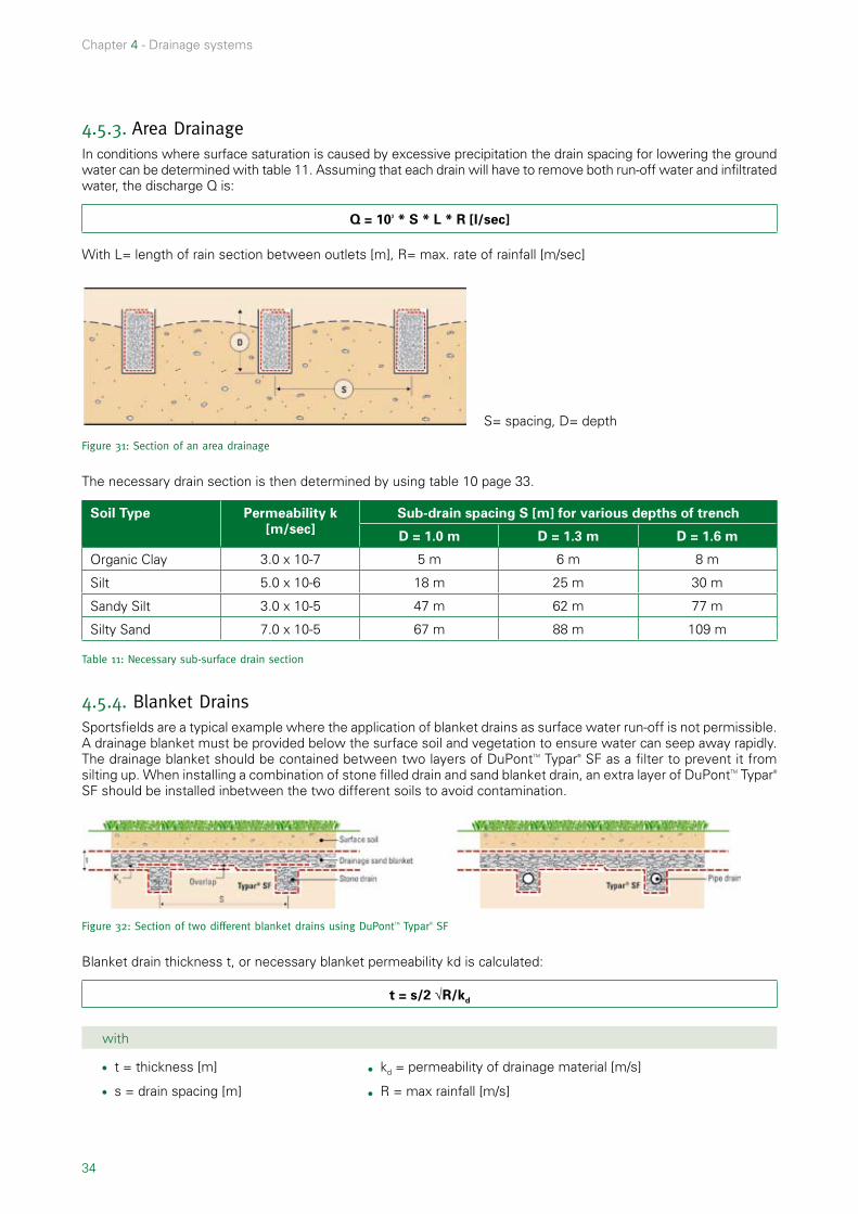
4.5.3. Area DrainageIn conditions where surface saturation is caused by excessive precipitation the drain spacing for lowering the ground water can be determined with table 11. Assuming that each drain will have to remove both run-off water and infiltrated water, the discharge Q is:
Q = 103 * S * L * R [l/sec]
With L= length of rain section between outlets [m], R= max. rate of rainfall [m/sec]
Figure 31: Section of an area drainage
The necessary drain section is then determined by using table 10 page 33.
Soil Type Permeability k [m/sec]
Sub-drain spacing S [m] for various depths of trench
D = 1.0 m D = 1.3 m D = 1.6 m
Organic Clay 3.0 x 10⁻⁷ 5 m 6 m 8 m
Silt 5.0 x 10⁻⁶ 18 m 25 m 30 m
Sandy Silt 3.0 x 10⁻⁵ 47 m 62 m 77 m
Silty Sand 7.0 x 10⁻⁵ 67 m 88 m 109 m
Table 11: Necessary sub-surface drain section
4.5.4. Blanket Drains Sportsfields are a typical example where the application of blanket drains as surface water run-off is not permissible. A drainage blanket must be provided below the surface soil and vegetation to ensure water can seep away rapidly. The drainage blanket should be contained between two layers of DuPontTM Typar® SF as a filter to prevent it from silting up. When installing a combination of stone filled drain and sand blanket drain, an extra layer of DuPontTM Typar® SF should be installed inbetween the two different soils to avoid contamination.
Figure 32: Section of two different blanket drains using DuPontTM Typar® SF
Blanket drain thickness t, or necessary blanket permeability kd is calculated:
t = s/2 √R/kd
with
l t = thickness [m] l kd = permeability of drainage material [m/s]
l s = drain spacing [m] l R = max rainfall [m/s]
S= spacing, D= depth

35
4
Chapter 4 - Drainage systems
As a sufficient safety margin we recommend a safety factor 10 to the permeability kd. Drain spacing s and drain section can be determined either by using table 10 or
Q = 103 * S * L * R [l/sec]
Note that the surface-soil has to be sufficiently permeable to pass the surface water to the drainage layer.
4.5.5. Composite Drainage
Figure 33: Installation of composite drainage as road shoulder drain
These products come in many shapes and sizes depending on the specific applications that they will be used in:
Civil engineering applications
l Road drains: edge drains, blanket drains, asphalt drains
l Waste disposals: gas venting or leachate collection
l Blanket drains under sport fields, …
l Agricultural pipe drains
l Vertical or wick drains
Construction applications
l Sheet drains for protection of underground walls, basements, parking lots...
l Blanket drains for terraces , green roofs, balconies, …
Composite drainage products are increasingly replacing traditional drainage systems consisting of aggregates wrapped into a geotextile. Their industrial manufacturing and ease of installation make them an economic alternative to the traditional drain.
For further information on these products, their applications and availability, please contact your local DuPontTM Typar® SF representative.
P P PP P P
Figure 34a: Reduction of drainage capacity due Figure 34b: DuPontTM Typar® SF and its superior performance to deformable filter fabric as a filter in a composite drainage system
During the last years, a new kind of drainage material has appeared on the geosynthetic market and is gaining rapid acknowledgement in the construction and civil engineering industry: composite drainage products.
A composite drainage product is composed of a rigid synthetic core surrounded by or wrapped into a geotextile filter. The core will have a rather open but uncompressible structure that allows the free flow of water even when installed. The filter will prevent the core of being clogged by the soil.

36
Chapter 4 - Drainage systems
4.6. Installation guidelinesIt is very important to cover Typar® SF as soon as possible after it has been rolled out. During rainfalls small particles are washed out of the soil and might dry on the geotextile forming an impermeable soil (clay) layer. The following guidelines for the different drainage systems should be followed when installing Typar® SF:
4.6.1. Trenches
Figure 35: Fix Typar® SF to avoid the fabric being pulled Figure 36: Enclose aggregate with Typar® SF and overlap down, allowing contamination of the drainage aggregate by at least 30cm
l The base and side walls of the trench should be as free of irregularities as possible (holes, roots, etc.). l Lay Typar® SF parallel to the trench and anchor the edges of the geotextile. l Do not drag the fabric in the mud. This can result in the deposit of a large amount of fine particles on the
surface of Typar® SF thus creating an impervious film. l Off-load the drainage aggregates carefully to avoid the sides of the fabric being dragged towards the bottom
of the trench.l Do not use over-large stones to fill up the trench. Gravel of a maximum size of 2cm is required to ensure good
fabric-to-soil contactl Compact the aggregate and enclose it with Typar® SF before backfilling to the top of the trench.l Overlap lengths of Typar® SF by at least 30cm
4.6.2. Blanket drainsl Overlap by a minimum of 30cm. l Do not unroll Typar® SF too far in advance, especially in windy conditions. l Use relatively small sized aggregate to ensure good fabric-to-soil contact.
Figure 37: Application of Typar® SF for a blanket drain
37
4
Chapter 4 - Drainage systems
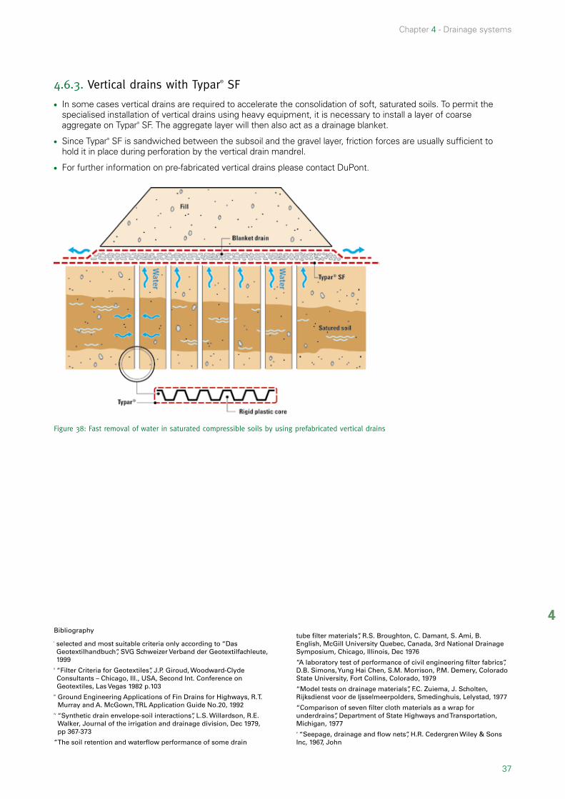
4.6.3. Vertical drains with Typar® SF
l In some cases vertical drains are required to accelerate the consolidation of soft, saturated soils. To permit the specialised installation of vertical drains using heavy equipment, it is necessary to install a layer of coarse aggregate on Typar® SF. The aggregate layer will then also act as a drainage blanket.
l Since Typar® SF is sandwiched between the subsoil and the gravel layer, friction forces are usually sufficient to hold it in place during perforation by the vertical drain mandrel.
l For further information on pre-fabricated vertical drains please contact DuPont.
Figure 38: Fast removal of water in saturated compressible soils by using prefabricated vertical drains
Bibliography
I selected and most suitable criteria only according to “Das Geotextilhandbuch”, SVG Schweizer Verband der Geotextilfachleute, 1999
II “Filter Criteria for Geotextiles”, J.P. Giroud, Woodward-Clyde Consultants – Chicago, Ill., USA, Second Int. Conference on Geotextiles, Las Vegas 1982 p.103
III Ground Engineering Applications of Fin Drains for Highways, R.T. Murray and A. McGown, TRL Application Guide No.20, 1992
IV “Synthetic drain envelope-soil interactions”, L.S. Willardson, R.E. Walker, Journal of the irrigation and drainage division, Dec 1979, pp 367-373
“The soil retention and waterflow performance of some drain
tube filter materials”, R.S. Broughton, C. Damant, S. Ami, B. English, McGill University Quebec, Canada, 3rd National Drainage Symposium, Chicago, Illinois, Dec 1976
“A laboratory test of performance of civil engineering filter fabrics”, D.B. Simons, Yung Hai Chen, S.M. Morrison, P.M. Demery, Colorado State University, Fort Collins, Colorado, 1979
“Model tests on drainage materials”, F.C. Zuiema, J. Scholten, Rijksdienst voor de Ijsselmeerpolders, Smedinghuis, Lelystad, 1977
“Comparison of seven filter cloth materials as a wrap for underdrains”, Department of State Highways and Transportation, Michigan, 1977V “Seepage, drainage and flow nets”, H.R. Cedergren Wiley & Sons Inc, 1967, John


39
5
5.1. Introduction 40
5.2. Functions 40
5.3. Selecting the correct DuPontTM Typar® SF style 41
5.3.1. Filter criteria 41
5.3.2. Energy criteria 41
5.4. Installation Guidelines: Erosion control systems with DuPontTM Typar® SF 42
Chapter 5
Erosion control

40
Chapter 5 - Erosion control
5.1. IntroductionErosion control is defined as: “The use of a geotextile or a geotextile-related product to prevent soil or other particle movements at the surface of, for example, a slope”23.
Figure 39: DuPontTM Typar® SF in an erosion control application
The erosion process is part of the geological cycle, a natural phenomenon, wherein water and air are particularly aggressive factors causing soil erosion. A geotextile is used as part of an erosion control system to protect the soil (sea embankment slopes, river banks, bed protection) from this influence. Depending on the water’s force (flow rate, wave action, tidal surges) and the characteristics of the soil the effects can be devastating (e.g. landslides).
5.2. FunctionsThe main function of the geotextile in an erosion control system is the retention of the basic material without the generation of unacceptable excess pore water pressure. The geotextile replaces a conventional well-graded filter between soil to be retained and gabions, rip-rap or concrete slabs revetments, which protect the filter geotextile. Its particular opening size retains the soil and so avoids erosion of the slope. Furthermore the geotextile must fulfill the strength requirements.
DuPontTM Typar® SF is the ideal filter for erosion control and is used to replace multi-phased aggregate filters because:
l Its strong, homogeneous, cohesive structure absorbs and dissipates frontal water forces more effectively thus resisting disintegration.
l Its permeability characteristics allow the passage of water while retaining soil particles thus eliminating long term hydrostatic pressure build-up.
l Its structure is more consistent in quality and uniformity compared to aggregates.
l It more effectively prevents the undermining of structures by preventing piping and scouring of soils around them.
5. Erosion control
23 EN ISO 10318.

41
5
Chapter 5 - Erosion control
5.3. Selecting the correct DuPontTM Typar® SF styleThe important elements to be considered by the engineer when designing drainage systems are the topography, water table, soil composition and characteristics of the drain and filter to be used. The selection of the geotextile filter must consider both the filter and energy absorption criteria.
5.3.1. Filter criteriaThe geotextile used in erosion control systems must satisfy the filter criteria under dynamic flow conditions (reversible flow), i.e. under the condition of satisfying the permeability requirement, the maximum opening size of the geotextile (O90) should be as small as possible. For example, for coarse soils (D40 ≥ 0.06mm 24), the following must be observed:
O90 ≤ D60 y O90 ≤ 1.5 * D10 * Cu
Concerning the permeability, the following aspects should be considered:
l Contact condition between subsoil and DuPontTM Typar® SF: For erosion control applications, the geotextiles may not be firmly connected with the subsoil locally because of the occurrence of ballooning effect of the geotextiles due to reversible water flow causing liquefaction of subsoil underneath the geotextiles and decomposition of the natural filter layer under the geotextiles. However, using small size gravel with particle size not more than 50mm to 100mm, good contact between the geotextile and the underlying soil can be achieved.
l The influence of the top layer on the permeability: The permeability of DuPontTM Typar® SF is adapted to that of the subsoil. However, situations may occur where adoption according to the permeability of the top layer is necessary. For instance if concrete blocks are applied directly on to the DuPontTM Typar® SF and there is minimal space between the geotextile and the blocks, the permeability of DuPontTM Typar® SF remains the same but cannot be utilised along the entire surface. The water from the subsoil must first be directed to the openings between the blocks. The effective permeable area is reduced. To eliminate this effect and to provide some additional protection against installation damages, a layer of gravel or sand is placed between the geotextile and the concrete blocks. Furthermore this protects the geotextile from possible UV exposure.
5.3.2. Energy criteriaDuring the construction of the erosion control system, the stone may be dumped on the geotextile. In this case a DuPontTM Typar® SF style with a high energy absorption potential is required, such as a style with an energy level 3 (see Fig. 22 and table 6).
When the subsoil locally deforms, while the adjacent part remains unchanged, large local tension deformation can occur in the geotextile. This local deformation can occur from two mechanisms: non-uniform settlement and transport of material underneath DuPontTM Typar® SF. Differential settlement can be caused by variation in the bearing capacity of the subsoil, variation in the top load and softening and plastic deformation. A high initial modulus can stabilise the underlying soil and reduce non-uniform settlement. Movement of material underneath the geotextile may result from excavations along the border of the geotextile or damage in form of wear or tear. A geotextile with a high energy absorption is optimally suited to withstand such harsh installation conditions and minimise potential damages.
24 EN ISO 10318

42
Chapter 5 - Erosion control
5.4. Installation Guidelines: Erosion control systems with DuPontTM Typar® SFl If possible, grade and compact slopes.
l If slope width is less than 8m, unroll DuPontTM Typar® SF along the length of the lower half of the slope first, then place DuPontTM Typar® SF on upper half of the slope with 0.5 to 1m overlap.
Figure 40: DuPontTM Typar® SF unrolled first on the lower half of the slope and then on the upper half
l If slope is over 8m, place DuPontTM Typar® SF in full-width lengths from slope top to bottom. Overlap in direction of waterflow.
l Excavate ditches for anchoring DuPontTM Typar® SF at top and toe of slope. The toe is the foundation of the structure and should get special attention to prevent undermining (see Fig. 41).
l When placing rip-rap or gabions, start at toe and work up the slope to prevent sliding. Install rip-rap smoothly, without dropping it from a big height on DuPontTM Typar® SF.
l To ensure good fabric-to-soil contact, first of all place a layer of bedding material (gravel) on the DuPontTM Typar® SF. This layer will also help prevent puncturing by heavy rip-rap.
l Anchor the fabric in the ditch at the top edge of the slope with soil and vegetation. This deep anchoring method will prevent large volumes of surface water from getting under the fabric and lifting the entire structure.
Figure 41: Anchoring DuPontTM Typar® SF at the top edge of the slope

43
5
Chapter 5 - Erosion control
Hydraulic applications:When installing the geotextile under water level DuPontTM Typar® SF floats on the water, because the density of polypropylene is lower than that of water (0.91). In order to hold the geotextile in place, sand or gravel need to be dropped on the geotextile immediately following the layout machine.
For rapid and consistent installation, attach steel rods (e.g. typical 6mm diameter reinforcement bar) every 5 metres. These rods will keep the fabric flat, thus allowing a regular overlap (no need for divers; smaller overlap = cost savings)
Figure 42: Attaching steel rods to DuPontTM Typar® SF will keep fabric flat and allows installation under water


45
6
Controlling capillary raise of saline water 46
Roof gardens 46
Vegetation irrigation along roads 47
Pathways with concrete slabs or paving stones 47
Drainage of foundation walls 47
Drainage of building foundations 47
Capillary break for building wall 48
Individual housing sewerage 48
Pipes on soft soil 48
Artificial beaches on lakes 49
Liner protection 49
Railways, new tracks and track renewal 49
Agricultural and pipe drains 49
Breakwater and jetties on soft soil sea bed 50
Land reclamation with hydraulic fill 50
Application suggestions
Chapter 6

46
Chapter 6 - Application suggestions
Apart from the most common applications in road, drainage and erosion control projects geotextiles are also widely utilised in a multitude of other applications such as:
l roofing systems
l landscaping
l building foundations
l foot paths etc.
Below special applications of Typar® are illustrated.
Controlling capillary raise of saline water.
l In arid countries intense surface evaporation causes the capillary rise of underlying salt water into fertile soil, to the detriment of vegetation.
l When newly installed, a granular capillary break will prevent capillary rise of salts. However downwash of fertile soil will eventually fill the granular material and again favour the capillary process.
l DuPontTM Typar® SF filter prevents downwash of soil.
l The efficient separation with DuPontTM Typar® SF permits installation of thinner capillary break layer.
l The installation of impervious coated Typar® at the bottom of the capillary break will retain irrigation water and/or allow irrigation water supply through the granular layer, thus diminishing evaporative losses and encouraging deep root growth.
l This system can also be used in normal conditions, the granular layer simply acting as a drainage or irrigation layer.
Roof gardensl Upper Typar® layer prevents downwash of humus
into the drainage layer.
l Bottom DuPontTM Typar® SF layer protects the waterproof membrane from puncturing and acts as a root barrier.
6. Application suggestions
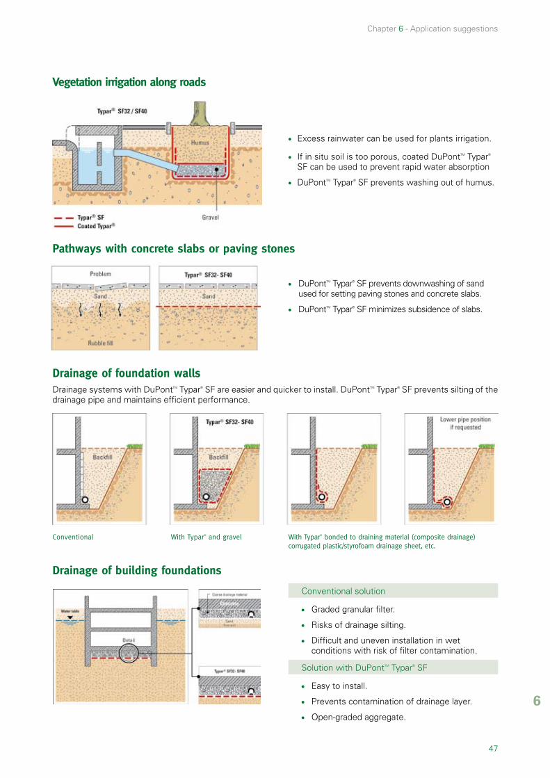
47
6
Chapter 6 - Application suggestions
Vegetation irrigation along roads
l Excess rainwater can be used for plants irrigation.
l If in situ soil is too porous, coated DuPontTM Typar® SF can be used to prevent rapid water absorption
l DuPontTM Typar® SF prevents washing out of humus.
Pathways with concrete slabs or paving stones
l DuPontTM Typar® SF prevents downwashing of sand used for setting paving stones and concrete slabs.
l DuPontTM Typar® SF minimizes subsidence of slabs.
Drainage of foundation wallsDrainage systems with DuPontTM Typar® SF are easier and quicker to install. DuPontTM Typar® SF prevents silting of the drainage pipe and maintains efficient performance.
Conventional With Typar® and gravel With Typar® bonded to draining material (composite drainage) corrugated plastic/styrofoam drainage sheet, etc.
Drainage of building foundations
Conventional solution
l Graded granular filter.
l Risks of drainage silting.
l Difficult and uneven installation in wet conditions with risk of filter contamination.
Solution with DuPontTM Typar® SF
l Easy to install.
l Prevents contamination of drainage layer.
l Open-graded aggregate.

48
Chapter 6 - Application suggestions
Capillary break for building walls
l In fine soils a high water table may rise by capillary effect into the building walls, causing wall humidity and revetment degradation.
l A coarse gravel layer will provide a capillary break.
l DuPontTM Typar® SF prevents the capillary break from being contaminated by fine soils.
Individual housing sewerage
l DuPontTM Typar® SF prevents contamination of gravel by fill or surrounding soil, thus allowing efficient biological transformation through good aeration of the gravel.
Pipes on soft soil
l DuPontTM Typar® SF allows clean installation of pipe-support material.
l Better compaction can be achieved.
l DuPontTM Typar® SF minimizes differential
settlement.

49
6
Chapter 6 - Application suggestions
Artificial beaches on lakes
l DuPontTM Typar® SF prevents sand from sinking into the muddy lake-shore.
l DuPontTM Typar® SF is easy to install.
l In northern countries, DuPontTM Typar® SF and sand can be laid on to frozen lake surface. When the ice melts they will deposit on the lake bed.
l DuPontTM Typar® SF prevents weed growth.
Liner protection
l DuPontTM Typar® SF between pond liner and supporting soil > SF56 (min).
l DuPontTM Typar® SF between pond lines and protective layer of sand > SF37.
l DuPontTM Typar® SF Provides protection against
puncturing.
Railways, new tracks and track renewal
l DuPontTM Typar® SF avoids ballast contamination by pumping effect due to dynamic loading.
l It allows better compacting and aggregate saving.
l DuPontTM Typar® SF retains soil particles without clogging.
l It ensures longer service life.
Agricultural and pipe drains
l A corrugated pipe wrapped with DuPontTM Typar® SF can be put into subsoil with or without digging a trench.
l The drainage surface of corrugated pipe is increased up to 90 times.
l The influence zone of wrapped drain is higher.
l Drain spacing can be increased.
l The stiffness of DuPontTM Typar® SF prevents fabric from entering the pipe corrugations.
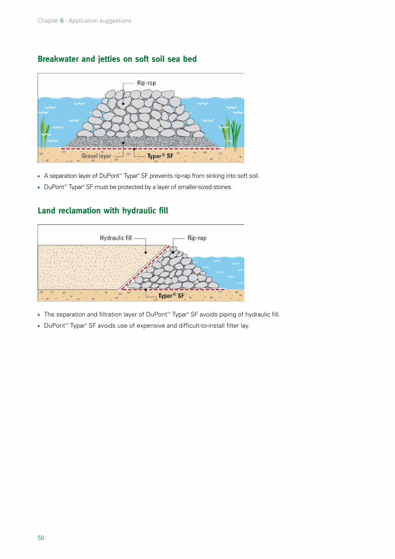
50
Chapter 6 - Application suggestions
Breakwater and jetties on soft soil sea bed
l A separation layer of DuPontTM Typar® SF prevents rip-rap from sinking into soft soil.
l DuPontTM Typar® SF must be protected by a layer of smaller-sized stones.
Land reclamation with hydraulic fill
l The separation and filtration layer of DuPontTM Typar® SF avoids piping of hydraulic fill.
l DuPontTM Typar® SF avoids use of expensive and difficult-to-install filter lay.

51 7
7.1. Standard Test Methods 52
7.1.1. Descriptive Properties 52
7.1.2. Mechanical Properties 52
7.1.3. Hydraulic Properties 53
7.2. Hydraulic Characteristics 54
7.3. Energy absorption 54
7.4. Comparison of properties 55
7.5. Raw materials 55
7.6. Durability 58
7.6.1. UV resistance 58
7.6.2. Oxidation resistance 58
7.6.3. Microbiological resistance 58
7.6.4. Chemical resistance 58
7.7. Temperature Resistance 58
7.7.1. Temperature Resistance 58
7.7.2. High temperatures 59
7.8. Joining Methods 58
7.8.1. Sewing 58
7.8.2. Overlap 59
7.9. Useful data 60
7.9. Specification Text 64
Geotextiles used to separate earthworks materials 64
Annex
Chapter 7

52
Chapter 7 - Annex
7.1. Standard Test MethodsSince geotextiles have been initially developed by the textile industry, geotextile properties were first measured using test standards for textiles. It soon became evident that these properties and standards were not relating well to the geotextile applications such as e.g. filtration and separation.
Institutes in different countries developed new test equipment and test methods more appropriate to the geotextile end-uses. But this also made it more difficult to compare the various products from different countries. Since several years the European Standard Tests provide a common basis (see 7.1.1 –7.1.3) and are applied not only throughout the European Union but accepted throughout Europe and have widely been adopted by ISO (International Standard Organisation).
The tests that are described below are so-called index tests. Index tests allow significant comparisons of different products when using the same test standard. But index tests are not providing any information on the soil-geotextile interaction. They only highlight one side of the geotextile’s properties. Contrary to performance tests, which are used to determine the performance of geotextiles under the specific site conditions for a defined application. They do not necessarily have to be field tests but can be carried out in a laboratory or as a large scale model.
7.1.1. Descriptive PropertiesThese properties are not indicative for the geotextile’s performance but simply describe the products physic.
Mass per Unit Area EN 965 –The mass is determined by the weight of small samples of known size, which have been taken along the full width and length of the sample.
Thickness at specified pressures EN 964-1 –The thickness of the geotextile is determined at pressures from 2 kPa to 200 kPa, which simulates the geotextile being in service.
7.1.2. Mechanical Properties
Wide-width tensile test EN ISO 10319
This test is performed for all kinds of geotextiles and geogrids on a specimen of 200mm width and 100mm length. A longitudinal force is applied to the specimen until it ruptures while the maximum tensile strength, the elongation and the energy absorption is measured. This test is similar to ASTM D4595. The main difference between this method and others such as DIN 53857, ASTM D1682 etc. is the width of the specimen or the rate of strain.
Static puncture test (CBR) EN ISO 12236
A steel plunger (50mm diameter)is pushed at a constant rate on the centre of the specimen which is clamped between two steel rings. Maximum push-through force and displacement at maximum force are measured. This test is similar to ASTM D6241.
Annex

53 7
Chapter 7 - Annex
Puncture Resistance (US Rod) ASTM D4833
This test is similar to the static puncture test (CBR) but a different plunger (ø 8mm) is used and the specimen is smaller. Koerner though recommends the CBR test because it gives more consistent resultsI.
Dynamic perforation test (cone drop test) EN 918
A steel cone is dropped from a distance of 50 cm on to the centre of a fixed geotextile specimen. The degree of penetration is measured by the hole diameter.
Grab Strength ASTM D4632 – the same
Trap Tear Strength ASTM D4533 – the same
200mm
100mm
76m
m
15mm
Hydraulic Bursting Strength of Textile Fabrics (Mullen burst test) ASTM D3786
An inflatable rubber membrane is used to deform the geotextile into a shape of a hemisphere of 30mm diameter until it bursts. Due to the small sample size and high variation in the test procedure, the results of this test vary widely. In the last revision of AASHTO M288 in 2000 this property has been removed from the list of mechanical properties for the installation survivability requirements!
7.1.3. Hydraulic PropertiesCharacteristic opening size EN ISO 12956 A defined graded granular material is washed through a single layer of the geotextile sample used as a sieve and the particle size distribution is established. O90,wet is the characteristic opening size of the geotextile determined from the particle size distribution.

54
Chapter 7 - Annex
Apparent Opening Size ASTM D4751 This test method covers the determination of the apparent opening size (AOS = O95) of a geotextile by sieving glass beads through a geotextile. A geotextile sample is placed in a sieve frame, and sized glass beads are placed on the geotextile surface. The geotextile and frame are vibrated to induce the beads to pass through the test specimen. The procedure is repeated on the same sample with various size distributions of glass beads until its apparent opening size O95(dry) has been determined from the particle size distribution.
Flow rate BS 6906-3 The flow of water with a 10 cm water head through a single layer of geotextile normal to the plane of the geotextile is measured under specified conditions [l/(s*m2)]. Note: This test has been replaced by EN ISO 11058.
Water permeability (Velocity Index) EN 11058 Constant head method: a single layer of the geotextile specimen is subjected to a unidirectional flow of water normal to the plane under a range of constant water heads. Falling head method: like the constant head method but with falling water head. The result is the velocity index VH50 (mm/s) corresponding to a head loss of 50 mm across a specimen, and the permittivity (s-1) (Conversion VH50 /50mm = (l/m2 * s)/mm = m/s). This test has been introduced in 1999 and since then is often confused with the permeability coefficient k due to the unit m/s. But the velocity index is a flow rate (m/s = l/m2 * s).
Permeability under load E-DIN 60500-4 The permeability coefficient k normal to the plane is measured under a constant water head, hydraulic gradient i = 1 and a range of different loads. This test is of particular interest when comparing geotextiles of different thickness since the hydraulic gradient is fixed at i = 1.
7.2. Hydraulic Characteristicsl The permeability k [m/s] describes the flow of water perpendicular to the plane and is measured by means of a
permeameter with demineralised and de-aerated water. The measurement of the flow rate Q and hydraulic gradient i allow the determination of the water permeability coefficient k= Q/i for a steady laminar flow (i < 3). The hydraulic gradient i is defined as the head loss dh divided by the thickness of the soil i= dh/ts. For geotextiles the formula is adapted using the thickness tg of the geotexile: i= dh/tg. Ideally for geotextiles a hydraulic gradient of i= 1 should be used thus eliminating the influence of the geotextile thickness. Otherwise products of different thicknesses but the same water flow will have different k-values and that is not correct (see also 4.3). As a general rule, the geotextile’s permeability should be higher than that of the soil in order to not reduce the water flow rate.
l Transmissivity Θ= k*tg [m2/s] describes the permeability in the plane or discharge capacity of a geosynthetic. Factors
such as the amount of fine particles caught in the structure of the geotextile (clogging) and soil pressure influence the transmissivity of a geotextile in service. While soil pressure can be simulated in the lab (foam plates under pressure), possible clogging or blinding cannot be foreseen in advance. Therefore the transmissivity is best applied to geosynthetics combining a drainage core and adequate filter, which ensures the long term discharge capacity. The transmissivity of “thick ”geotextiles measured in a laboratory does not reflect the discharge capacity on the site.
l The permittivity Ψ= k /tg [s-1] is the ratio of k divided by the thickness tg of the geotextile. This value allows comparing
geotextiles of different thickness.
7.3. Energy absorptionl Definition: “Energy absorption, W” – Work done to elongate the specimen defined as the integral of the
stress-strain curve (to a chosen point) and expressed in kJ/m2 or kN/m.
l Energy absorption W at maximum load (based on EN 10319): Calculate the energy absorption W, expressed in kilojoules per metre (or kN/m²), directly from the data obtained from the tensile testing machine, using the following equation:
W= 0∫ Ff Ff(x) dx*c*d [kJ/m2]
F(x) is the recorded function of the stress strain curve d= 1/H, where H is the specimen nominal height in metres c is obtained from the equation (1)or equation (2) as appropriate:
For nonwovens, closely woven fabrics or similar materials, c= 1/B (1) where B is the specimen nominal width in metres.
For coarse-woven geotextiles, geomeshes, geogrids or similar open-structure materials,c= Nm /Ns (2)where Nm is the minimum number of tensile elements within 1m width of the product being tested and Ns is the number of tensile elements within the test specimen.

55 7
Chapter 7 - Annex
7.4. Comparison of propertiesEngineers are frequently required to compare the properties of different brands of geotextiles. Often the properties are given according to different norms or the products differ strongly (such as a woven and a nonwoven material) which makes it difficult to compare them. A good and easy method of comparing these is to compare the energy absorption similar to the method recommended by the Swiss Geotextile Committee. It is a valid comparison because the energy absorption is a combination of properties. A geotextile with a high tensile strength but a low elongation may have the same energy as an-other with a lower tensile strength and a high elongation. So when comparing tensile strength and elongation alone the products would not seem equivalent.
Figure 43: Difference between the actual and theoretical energy absorption potential shown with stress-strain curves of two different geotextiles.
It is a comparison of the resistance to installation and construction stresses. As illustrated in the second chapter, the geotextile’s resistance to damage is achieved primarily as a combination of high tensile strength and high elongation at break (energy absorption).
In several countries the theoretical energy absorption (Windex = 0.5 * T * ε) is used, which is a simplification. The actual energy absorption potential W is more accurate and should be the value used because this takes into account the characteristics of the stress-strain curve (e.g. the initial modulus).
7.5. Raw materialsA whole range of different polymers is used for the production of geotextiles, the most common being polypropylene and polyester. Each polymer has its own advantages and disadvantages. The typical density and melting temperature are listed in the following table.
PP PET PA HDPE
Density (g/cm3) 0.91 1.38 1.12 0.95
Melting temperature (°C) 165 260 220-250 130
l Polypropylene (PP) is a thermoplastic long chain polymer which has a high stiffness, good tensile properties and resistance to acids and alkalis.
l Polyamide (PA) is a thermoplastic which has a high strength, high wear and abrasion resistance and good chemical resistance.
l Polyethylene (PE) used in its high density form HDPE is a thermoplastic with a high strength and stiffness and a good resistance to chemicals.
l Polyester (PET) is a thermoplastic with a high strength, a low creep strain rate and good chemical resistance to most acides and many solvents. Although for applications of polyester in highly alkaline environments with pH > 10, particularly in the presence of lime, cement or concrete further testing should be considered.

56
Chapter 7 - Annex
7.6. DurabilityIn the production process stabilisers are added to the polypropylene to increase the durability of DuPontTM Typar® SF.
7.6.1. UV resistanceDuPontTM Typar® SF can endure up to several weeks in direct sunlight, but prolonged exposure, particularly in tropical sunlight, can cause strength losses. Generally a geotextile should be covered immediately after laying to avoid UV degradation, wind uplifting or mechanical damage. According to EN 12224, DuPontTM Typar® SF should be covered within 2 weeks after installation.
7.6.2. Oxidation resistanceNumerous accelerated ageing tests have shown that the resistance of DuPontTM Typar® SF highly exceeds a lifetime of 100 years. And also according to CE Marking requirements, Typar® SF is predicted to be durable for a minimum of 100 years in all natural soils.
The oxidation resistance according to prEN ISO 13438 is:
l Oven test >100% retained strength
l High pressure test >100% retained strength
7.6.3. Microbiological resistanceTypar is made of 100% polypropylene which makes it resistant to rot and moisture.The microbiological resistance according to EN 12225 is 100% retained strength.
7.6.4. Chemical resistanceThe chemical resistance according to EN 14030 is:
l for acid environment (method A) 100% retained strength
l for alkali environment (method B) 100% retained strength
Note: for oxidation, microbiological and chemical resistance > than 50 % retained strength is acceptable.
Agent Conc.% Temp. °CTime,
Hours/MonthsEffect on
DuPontTM Typar® SF 1
Acids
Acetic 100 20° 6 months None
Chromic 10 21° 10 hrs. None
Hydrobromic 10 21° 10 hrs. None
Hydrochloric 10 21° 1000 hrs. None
Hydrochloric 37 71° 10 hrs. None
Nitric 10 99° 10 hrs. None
Nitric 70 21° 10 hrs. None
Nitric 95 21° 1000 hrs. Considerable
Phosphoric 85 21° 10 hrs. None
Sulphuric 60 99° 10 hrs. None
Sulphuric 96 21° 1000 hrs. None
Formic 100 20° 6 months None
Hydrochloric 30 60° 6 months None
Hydrochloric 30 100° 6 months Degraded
Sulphuric 98 20° 6 months None
Sulphuric 98 60° 6 months Considerable
Sulphuric 98 100° 6 months Degraded

57 7
Chapter 7 - Annex
Agent Conc.% Temp. °CTime,
Hours/MonthsEffect on
DuPontTM Typar® SF 1
Alkalis
Ammonia 30 20° 6 months None
Ammonia 58 21° 1000 hrs. None
Sodium Hydroxide 50 21° 6 months None
Sodium Hydroxide 50 60° 6 months None
Sodium Hypochlorite 20 20° 6 months None
Sodium Hypochlorite 20 100° 6 months Considerable
Organic Chemicals
Acetone 100 20° 6 months None
Acetone 100 56° 6 months None
Benzene 100 21° 1000 hrs. None
Benzene 100 20° 6 months Moderate
Benzene 100 60° 6 months Considerable
Carbon Tetrachloride 100 20° 6 months Considerable
Cyclohexanone 100 20° 6 months None
Cyclohexanone 100 60° 6 months Considerable
Ethanol 96 20° 6 months None
Ethanol 96 60° 6 months None
Ethanol 96 81° 6 months None
Ethylene Glycol 100 20° 6 months None
Ethylene Glycol 100 60° 6 months None
Dimethyl Formamide 100 93° 10 heures None
Dimethyl Formamide 100 153° 10 hrs. Degraded
Dimethyl Sulphoxide 100 93° 10 hrs. None
Gasoline 100 20° 6 months Considerable
Linseed Oil 100 20° 6 months None
Linseed Oil 100 60° 6 months None
Methylene Chloride 100 20° 6 months Considerable
Perchloroethylene 200 93° 10 hrs. Considerable
Perchloroethylene 250 121° 10 hrs. Degraded
Stoddard Solvent 100 93° 10 hrs. None
Transformer Oil 100 20° 6 months None
Transformer Oil 100 60° 6 months Considerable
Trichloroethylene 100 20° 6 months Considerable
Turpentine 100 100° 6 months None
Xylene, meta 100 93° 10 hrs. None
Xylene, meta 100 20° 6 months Considerable
1 Change in breaking strength caused by exposure:
None: 90% through 100% of original strength retainedSlight: 80% through 89% of original strength retainedModerate: 60% through 79% of original strength retainedConsiderable: 20% through 59% of original strength retainedDegraded: 0% through 19% of original strength retained

58
Chapter 7 - Annex
7.7. Temperature Resistance
7.7.1. Low temperaturesResistance to low temperatures is important if the geotextile is to be used in cold areas such as Alaska, Northern Scandinavia etc. Under extremely cold conditions the tensile strength will increase, along with a decrease in elongation of a few percent. This effect is reversible as the temperature is increased. No significant tensile strength changes were observed on a DuPontTM Typar® SF of 200g/m2 after 4 cycles of 0 to –18°C both wet and dry. Since DuPontTM Typar® SF does not absorb water, rolls will not freeze.
7.7.2. High temperaturesThe tensile strength will decrease and elongation increase at high temperatures. The hydraulic properties are little affected. For more details please contact the DuPont Geosynthetics Technical Centre.
7.8. Joining Methods
7.8.1. SewingSewing DuPontTM Typar® SF for wide width support, drainage and erosion control installations is a practical method of eliminating fabric overlap and reducing its cost. Sewing is the most reliable jointing method, especially because it can easily be performed on site while welding and gluing require a clean and dry work space.
A recommended seam type is shown in figure 44 below. The sewing machine should be adjusted to give 2 stitches/cm. Even though a sewn seam is the preferred choice a welded or glued seam can also give good results regarding the tensile strength. For more details please contact the DuPont Geosynthetics Technical Centre.
Figure 44: Recommended seam style

59 7
Chapter 7 - Annex
7.8.2. Overlap
The required side and end overlaps depend on soil properties (CBR), the project nature and on the deformations, which might occur. In general the following overlaps are used:
l Drainage systems: min 30cm
l Parking lots, permanent roads: 30 to 50cm
l Erosion control systems: 50 to 100cm
l Temporary roads: see figure 45
Figure 45: Overlapping of DuPontTM Typar® SF for temporary roads
The following graph shows the extra amount of DuPontTM Typar® SF needed when overlapping depending on the surface area and the overlap width. Estimates of the possible savings by sewing or welding instead of overlapping are clearly demonstrated.
Figure 46: Necessary surface depending on width of overlap
For applications where DuPontTM Typar® SF is used for reinforcement purposes, overlapping requires special attention. Calculations by experienced design engineers may be needed to check the correct transmission of stresses.

60
Chapter 7 - Annex
7.9. Useful dataApproximate range of soil properties for the most common types of soil (for preliminary design).
Soil Property SymbolSI
Unit
Sand
Gravel
Gravely riprap non- uniforme
Angular riprap
sandfree
Cobbles
LooseMedium dense Dense
Sand free
With gravel and sand
Unit weight,
dry soil
saturate soil g
kN/m3
kN/m3
17
19
18
20
19
21
18
20
20
21
17
-
17
-
19
20
Porosity
Permeability coefficient
Height of capillary rise
n
k
hk
%
cm/sec
cm
45
10-1
20
35
10-2
25
25
10-3
30
25 - 45
100
1 - 5
20 - 35
10-2
25
40 - 60
101
-
40 - 50
101
-
25 - 45
100
20
Simple Proctor density
Optimum moisture content
p
Wopt
kN/m3
%
17 - 20
6 - 10
19
5
22
7
-
-
-
-
-
-
Stiffness modulus
Deformation modulus
CBR value
ES
EV1
CBR
MN/m2
MN/m2
%
20 - 50
15 - 40
10 -20
40 - 100
30 - 60
20 - 30
80 - 150
50 - 80
30 - 40
100 - 200
70 - 120
50
150 - 250
100 - 150
70
100 - 200
70 - 120
90 - 100
100 - 150
60 - 100
100
150 - 250
100 - 150
90 - 100
Effective friction angle 30 32,5 35 37,5 37,5 40 35 37,5
Table 12: non-cohesive soils
Clay
Drift loam
Loam, mari
SiltOrganic clay, silt PeatSoil Property Symbol SI Unit
Semi solid Stiff Soft Stiff Soft
Unit weight g kN/m3 19 18 17 21 21 19 18 15 11
Porosity
Natural moisture content
n
w
%
%
50
20
60
30
70
40
30
10
30
15
40
20
40
30
60
80
90
400
Liquid limit
Plastic limit
Plasticity index
WL
Wp
lp
%
%
%
40 - 100
20 - 30
20 - 70
30
15
15
20 - 40
10 - 20
10 - 25
15 - 30
10 - 15
5 - 15
70 - 120
20 - 30
50 - 90
-
-
-
Permeability coefficient
Height of capillary rise
k
hk
cm/sec
m
10-7 - 10-9
5 - 100
10-5
1 - 5
10-6 - 10-8
1 - 5
10-5
1 - 5
10-8
1-5
10-3
-
Simple proctor density
Optimum moisture content
p
wopt
kN/m3
%
14 - 17
15 - 30
18 - 22
10 - 15
17 - 19
12 - 20
17-19
12-20
14-17
20-25
-
-
Stiffness modulus
Deformation modulus
CBR value
Es
Ev1
CBR
MN/m2
MN/m2
%
5 - 10
3 - 8
2 - 5
2 - 5
1 - 4
1 - 3
1 - 3
0,5 - 2
0 - 2
30 - 100
15 - 50
10 - 20
5-20
5-15
3-10
4 - 8
3 - 6
2 - 5
3-10
2-8
1-5
1-5
1-3
0-2
0,5 - 2
0 - 1
0
Effective friction angle
Effective soil cohesion
Effective shear strength
c’
cu
.
MN/m2
MN/m2
20
25
40 - 100
17,5
20
20 - 60
15
10
5 - 40
15
25
200 - 500
25
10
50 - 200
22,5
0
40 - 100
25
0
20 - 100
17,5
10
5 - 40
15
0
0
Consollidation coefficient cv m2/sec 10-6 - 10-9 - 10-5 - 10-7 10-4 10-7 - 10-9 10-3
Table 13: cohesive soils.

61 7
Chapter 7 - Annex
Figure 47: (b) Soil retention criteria for geotextile filter design under dynamic flow conditions. (after Luettich et al. [6])

62
Chapter 7 - Annex
% particles
Plas. index l(%)
Typical permeability
K(m/s)Designation <0.006 0.06-2mm >2mm
GW Well-graded gravel, sandy gravel < 5 VAR > 50 - 10-1 - 10-4
GP Poorly-graded, sandy gravel < 5 VAR > 50 - 10-1 - 10-4
GM Silty gravel, G + S + M < 15 VAR > 50 < 7 10-5 - 10-8
GC Clayey Gravel, G + S + C < 15 VAR > 50 > 7 10-8 - 10-10
SW Well graded sand, gravelly sand < 5 > 50 VAR - 10-2 - 10-5
SP Poorly graded sand, gravelly sand < 5 > 50 VAR - 10-2 - 10-5
SM Silty sand < 15 > 50 VAR < 7 10-5 - 10-8
SC Clayey sand < 15 > 50 VAR > 7 10-8 - 10-10
ML Silt, very fine sands > 50 ~ 50 VAR < 4 10-5 - 10-8
CL Clay > 50 ~ 20 VAR > 7 10-8 - 10-10
GM - ML Silty gravel > 15 VAR > 40 < 4 10-5 - 10-8
GM - GC Clayey-silty gravel > 15 VAR > 40 4 - 7 10-8 - 10-10
GC - GL Clayey gravel > 15 VAR > 40 > 7 10-8 - 10-10
SM - ML Silty sand - sandy silt 15 - 50 ~ 50 VAR < 4 10-5 - 10-8
SM - SC Clayey-silty sand 15 - 50 ~ 40 VAR 4 - 7 10-8 - 10-10
SC - CL Clayey sand - sandy clay 15 - 50 ~ 40 VAR > 7 10-8 - 10-10
CL - ML Clayey silt > 50 VAR VAR 4 - 7 10-7 - 10-10
OL Organic silt > 50 VAR VAR > 10 -
OH Organic Clay > 50 VAR VAR > 20 -
PT Peat - - - - -
Table 15: USCS soils classification
Figure 48: USCS soils classification based on plasticity index

63 7
Chapter 7 - Annex
Tableau 16: Correlation chart for estimating unsoaked CBR values from soil strength or property values.

64
Chapter 7 - Annex
7.10. Specification Text
Geotextiles Used to Separate Earthworks Materials
______ m2 geotextile shall be delivered and installed.
Specification for DuPont DuPontTM Typar® SF ______ or equivalent.
Thermally bonded nonwoven manufactured
l from 100% Polypropylene continuous filament
l according to Quality system ISO 9001, ISO 14001
Compressibility ratio at 200kN/2kN EN 964 < 15 %
Energy absorption EN ISO 10319 ≥ ____ kN/m or kJ/m2
Tensile strength EN ISO 10319 ≥ ____ kN/m
Tensile strength at 5% elongation EN ISO 10319 ≥ ____ kN/m
Elongation EN ISO 10319 ≥ ____ %
Puncture strength CBR EN ISO 12236 ≥ ____ N
Dynamic Cone Puncture EN 918 ≤ ____ mm
Tear Strength ASTM D4533 ≥ ____ N
Velocity index EN ISO 11058 ≥ ____ mm/s
Water permeability at 20kN/m2 DIN 60500 ≥ ____ 10-4 m/s
Pore opening size O90 EN ISO 12956 ≤ ____ _m (microns)
The geotextile fabric shall be UV stabilised and inert to chemicals commonly encountered in soil and water.
Geotextile rolls shall be furnished with suitable wrapping for protection and each roll shall be labelled and identified for field identification as well as for inventory and quality control purposes.
The surface to receive the geotextile fabric shall be prepared to a relatively smooth condition, free of obtrusions, depressions, and debris. Geotextile installation shall proceed in the direction of construction. Longitudinal joints in the fabric shall have a minimum overlap of 30cm, sewn or otherwise specified by the Engineer. In the event construction machinery is used to place the fabric, the working platform for the machinery shall be the soil and not the previously laid geotextile.
Bibliography
I R.M. Koerner, Designing with Geotextiles, p.110, Fourth Edition, 1999, Prentice Hall

For further information please contact us:DuPont de Nemours (Luxembourg) s.à r.l.DuPontTm Typar® GeosyntheticsL-2984 LuxembourgTel. : +352-3666 5779Fax : +352-3666 5021www.typargeo.comE-mail: [email protected]
DuPontTm Typar® Geosynthetics
• Typar® SF brochure
• Recommended Typar® SF styles
• Typar® datasheets
• Typar® HR product and design guide
• HR reinforcement geocomposite brochure
• Typar® case histories
other publications
Other publications from DuPontTM Typar® Geosynthetics:
01/2010 Copyright © 2010 DuPont. All rights reserved. The DuPont Oval Logo, DuPontTM, The miracles of scienceTM and Typar® are registered trademarks or trademarks of E. I. du Pont de Nemours and Company or its affiliates.