
TECHNICAL DOCUMENTATION WOLF CYLINDER SYSTEMS€¦ · 04 Space saving steel stratification buffer...
32
30m 3 /h WOLF CYLINDER SYSTEMS TECHNICAL DOCUMENTATION
Transcript of TECHNICAL DOCUMENTATION WOLF CYLINDER SYSTEMS€¦ · 04 Space saving steel stratification buffer...

30m3/h
WOLFCYLINDER SYSTEMS
T E C H N I CA L D O C U M E N TAT I O N

THE EXTENSIVEEQUIPMENT RANGEfrom system supplier WOLF offers the ideal solution for commercial and
industrial buildings, new build and modernisation projects alike.
The range of WOLF control units can meet any requirement for heating convenience.
All equipment is easy to operate, highly energy efficient and reliable.
Solar thermal systems can be swiftly integrated into existing systems.
WOLF equipment is easy and quick to install and maintain.

03WOLF CYLINDER SYSTEMS
STRATIFICATION BUFFER CYLINDERS BSP, BSP-SL, BSP-W, BSP-W-SL 04
ACCESSORIES 04
COMBINATION OPTIONS 06
SPECIFICATION 07
STRATIFICATION BUFFER CYLINDERS BSH 08-09
SPECIFICATION 10-11
SPU-2-W, SPU-2 500 UP TO 1500 LITRES 12-13
SPECIFICATION 14-15
SPU-2 2000 UP TO 5000 LITRES 16
SPECIFICATION 17
FRESHWATER MODULE FWS-2 18
SPECIFICATION 19
DHW CHARGING CYLINDERS SEL 20
SPECIFICATION 21
LS-2 CYLINDER CHARGING MODULE 22
SPECIFICATION 23
SOLAR DHW CYLINDERS SEM-1, SEM-2 24
ACCESSORIES 25
SPECIFICATION 26
DHW CYLINDERS SE-2 27
ACCESSORIES 28
SPECIFICATION 29
NOTES 30-31

04
Space saving steel stratification buffer cylinder
with quality certificate
Hydraulic components, such as the freshwater module, 2 circuits with mixer and solar pump assembly, can be mounted on the cylinder itself or on the wall
Stratification separators stabilise the temperature layers inside the cylinder and improve
the solar yield significantly
Highest possible solar yields, as the cylinder can be heated up to 95 °C without risk of scaling or scalding
Hygienic DHW heating with a powerful
freshwater module with high efficiency
pump (EEI < 0.20)
Push-fit connections enable DHW circulation
set to be retrofitted; control via time switch,
thermostat or by opening the tap
As option with 2 mixer circuit assemblies for high and low
temperature circuits
Single cylinder system for the
lowest heat losses
Affordable solution for central heating backup
Thermal insulation removable for easier transport into the installation room
5 year statutory warranty on the floorstanding cylinder; 2 years on electrical and moving parts
BSP STRATIFICATION BUFFER CYLINDERS
BENEFITS OF THE WOLF BSP STRATIFICATION BUFFER CYLINDER

05WOLF CYLINDER SYSTEMS
STRATIFICATION BUFFER CYLINDERSACCESSORIES
BSP / BSP-SL / BSP-W / BSP-W-SL
BSP-MK 1 MIXER CIRCUIT ASSEMBLY FOR LOW TEMPERATURE HEATING CIRCUIT
For direct mounting on the BSP / BSP-SL cylinder
Consisting of: DN15-50 high efficiency pump (EEI < 0.23), self-regulating, fitted mixer motor (230 V/210 s), 3-way mixer DN20 Kvs=4.0, 2 ball valves in the flow and 2 in the return for servicing without buffer or draining the heating system, integrated gravity brake to prevent incorrect circulation, overflow valve, bypass choke to set a constant proportion of water to be mixed into the return, thermometer, connections with flat gaskets, well designed EPP thermal insulation shells.
BSP-MK 2 MIXER CIRCUIT ASSEMBLY FOR HIGH TEMPERATURE HEATING CIRCUIT
For direct mounting on the BSP / BSP-SL cylinder
Consisting of: DN15-50 high efficiency pump (EEI < 0.23), self-regulating, fitted mixer motor (230 V/210 s), 3-way mixer DN20 Kvs=4.0, 2 ball valves in the flow and 2 in the return for servicing without buffer or draining the heating system, integrated gravity brake to prevent incorrect circulation, overflow valve, bypass choke to set a constant proportion of water to be mixed into the return, thermometer, connections with flat gaskets, well designed EPP thermal insulation shells. BSP-MK 1 and 2 mixer circuit assembly for low temperature heating circuit.
BSP-MK 1 AND 2 MIXER CIRCUIT ASSEMBLY FOR LOW TEMPERATURE HEATING CIRCUIT AND HIGH TEMPERATURE HEATING CIRCUIT
For direct mounting on the BSP / BSP-SL cylinder
Consisting of: Two DN15-50 high efficiency pumps (EEI < 0.23), self-regulating, two fitted mixer motors (230 V/210 s), two 3-way mixers DN20 Kvs=4.0, 2 ball valves in each flow and 2 in each return for servicing without buffer or draining the heating system, integrated gravity brakes to prevent incorrect circulation, overflow valves, bypass chokes to set a constant proportion of water to be mixed into the return, thermometer, connections with flat gaskets, well designed EPP thermal insulation shells.
ZP-3 DHW CIRCULATION PUMP KIT TO EXTEND THE FRESHWATER MODULE
Consisting of:
High efficiency DHW circulation pump, with thermostat shutdown and time switch, ball valve and offset fitting (activation from draw-off point or by means of integrated time switch).

06
BSP-W-1000
Stratification buffer cylinder for DHW heating and central heating backup via WOLF heat pump with removable thermal insulation and one smooth tube indirect coil
BSP-W-SL-1000
Stratification buffer cylinder for DHW heating and central heating backup via WOLF heat pump with removable thermal insulation and two smooth tube indirect coils
WRSWRS
STRATIFICATION BUFFER CYLINDERSFOR COMBINATION WITH SOLAR, BIOMASS AND OIL/GASBSP / BSP-SL / BSP-W / BSP-W-SL
STRATIFICATION BUFFER CYLINDERSFOR COMBINATION WITH SOLAR AND HEAT PUMPBSP / BSP-SL / BSP-W / BSP-W-SL
BSP 800/1000
Stratification buffer cylinder for DHW heating and central heating backup with removable thermal insulation and one smooth tube indirect coi
WRS
BSP-SL-1000
Stratification buffer cylinder for DHW heating and central heating backup with removable thermal insulation and two smooth tube indirect coils
WRS

07WOLF CYLINDER SYSTEMS
TYPE BSP 800 1000 SL-1000 W-1000 W-SL-1000Cylinder capacity litres 785 915 900 915 900
Standby heat loss kWh/24 h 3.18 3.22 3.22 3.22 3.22
Solar return (lower indirect coil) A mm 230 230 230 230 230
Solar sensor (lower indirect coil) B mm 490 550 550 550 550
Changeover valve sensor C mm 800 950 950 950 950
Solar flow (lower indirect coil) D mm 910 1030 1030 1030 1030
Common sensor E mm 1200 1350 1350 1350 1350
Cylinder sensor F mm 1350 1510 1510 1510 1510
Solar return (upper indirect coil) G mm - - 1443 - 1443
Solar sensor (upper indirect coil) H mm - - 1610 - 1610
Solar flow (upper indirect coil) I mm - - 1780 - 1780
Total height excl. thermal insulation J mm 1755 2040 2040 2040 2040
Total height incl. thermal insulation K mm 1825 2110 2110 2110 2110
Connection L mm 260 310 310 310 310
Connection M mm 630 745 745 745 745
Connection N mm 1030 1250 1250 1250 1250
Connection O mm - 1430 1430 1430 1430
Connection P mm 1430 1710 1710 1710 1710
Diameter incl. thermal insulation Q mm 1000 1000 1000 1000 1000
Diameter excl. thermal insulation R mm 790 790 790 790 790
Height when tilted, excl. thermal insulation mm 1788 2068 2068 2068 2068
Solar flow / return G 1 1 1 1 1
Connection Rp 1½ 1½ 1½ 1½ 1½Sensor (4 pce), internal diameter(for BSP-SL/BSP-W-SL: 5 pce)
mm 10 10 10 10 10
Solar internal indirect coil surface area, lower / upper coil m² 2.5 / - 3.0 / - 3.0 / 1.9 3.0 / - 3.0 / 1.9
Solar internal indirect coil capacity, lower / upper coil litres 16.5 / - 19.8 / - 19.8 / 11.0 19.8 / - 19.8 / 11.0
Max. operating pressure, cylinder bar 3 3 3 3 3
Max. operating pressure, indirect coil bar 6 6 6 6 6
Max. operating temperature, cylinder °C 95 95 95 95 95
Weight kg 171 194 215 194 215
* With thermostat factory-set to 3.25
Freshwater module FWS-2-60 FWS-2-80
DHW output at cold water temperature 10 °Cat 70 °C buffer/DHW temperature 60 °C
l/min 15* 27
DHW output at cold water temperature 10 °Cat 65 °C buffer/DHW temperature 45 °C
l/min 25* 40
DHW output at cold water temperature 10 °Cat 50 °C buffer/DHW temperature 45 °C
l/min - 25
Max. heating operating pressure bar 3 3
Max. water operating pressure bar 10 10
Max. operating temperature °C 95 95
Power consumption W 45 48
Weight kg 17 20
Electrical connection 230 V / 50 Hz
Q
R
M
LA
D
B
N
P G
H
O
C
E
F
I
J
K
STRATIFICATION BUFFER CYLINDERSSPECIFICATION
BSP / BSP-SL / BSP-W / BSP-W-SL

08
BSH BUFFER CYLINDERS
Maintenance of temperature stratification inside the
buffer cylinder through the use of a circulation lance
(accessory)
Hygienic DHW heating according to the instantaneous water heating principle with stainless steel DHW indirect coil
Lowest cool-down losses and minimal space requirement
through single cylinder system
Space saving steel buffer cylinder with quality certificate
No DHW charging pump
required
Variable matching of the "standby section"
for DHW heating through adjustable
positioning of the cylinder sensor via the sensor clamping strip
Higher solar yield through large solar indirect coils and permanent cooling
of the lower cylinder section during DHW heating
Low scaling tendency, even up to 70 °C
Higher draw-off capacity available temporarily through large water content inside the DHW indirect coil (48 - 80 litres depending on cylinder size)
Thermal insulation removable for easier transport into the installation room
5 year statutory warranty on the floorstanding cylinder; 2 years on electrical and moving parts
BENEFITS OF THE WOLF BSH BUFFER CYLINDER

09WOLF CYLINDER SYSTEMS
BUFFER CYLINDERSBSH-500/800/1000/1500/2000
BSH 500
Buffer cylinder with integral corrugated stainless steel pipe for DHW heating and central heating backup, with removable thermal insulation and one smooth tube indirect coil
WRS
BSH 800 to 2000
Buffer cylinder with integral corrugated stainless steel pipe for DHW heating and central heating backup, with removable thermal insulation and two smooth tube indirect coils
WRS

10
I
J
K/LM
NO
PQ
R
A
B
C
D
F
G
H
E
S
UV
WX
TK
LA
30°
I
J
K/LM
NO
PQ
R
A
B
C
D
F
G
H
E
S
UV
WX
TK
LA
30°
BUFFER CYLINDERSSPECIFICATIONBSH-500/800/1000/1500/2000

11WOLF CYLINDER SYSTEMS
1) 10/45 °C (DHW temp.), 70 °C (buffer temp.)2) Energy class according to Ecodesign Directive for cylinders ≤ 500 l
TYPE BSH 500 800 1000 1500 2000
Energy efficiency class2) B - - - -
Total cylinder capacity litres 495 800 900 1500 1965
Standby heat loss kWh/24 h 1.9 2.32 2.4 3.03 3.6
DHW capacity litres 48 60 60 70 80
Continuous cylinder output1) kW - l/h 24 - 594 38 - 940 50 - 1200 75 - 1848 100 - 2515
Output factor1) NL
2.1 4.3 5.4 6.5 7.6
Cold water connection A mm 240 270 270 335 350
Thermometer / sensor B mm 440 570 580 600 750
Electric booster heater C mm 820 920 1130 1130 1210
Thermometer D mm 1150 1290 1500 1500 1470
Thermometer / sensor E mm - - - - 1730
DHW connection F mm 1420 1580 1760 1825 1950
Height excl. thermal insulation / air vent valve G mm 1650 1840 2020 2150 2290
Height incl. thermal insulation H mm 1730 1940 2120 2250 2390
Diameter excl. thermal insulation I mm 650 790 790 1000 1100
Diameter incl. thermal insulation J mm 850 1030 1030 1240 1340
Stratification return / connection K / L mm 150 170 170 235 250
Solar return, bottom M mm 280 310 310 375 390
Sensor well, solar cylinder sensor, bottom N mm 490 465 495 520 630
Solar flow, bottom O mm 700 670 730 765 870
Sensor well, buffer sensor P mm 800 770 840 875 970
Connection Q mm 910 870 950 975 1080
Connection R mm 1020 980 1060 1085 1190
Solar return, top S mm - 1090 1210 1195 1300
Connection T mm - - - 1305 1410
Sensor well, cylinder sensor U mm 1150 1190 1330 1415 1520
Sensor well, solar cylinder sensor, top V mm - 1290 1450 1525 1640
Connection W mm 1400 1390 1520 1635 1760
Solar flow, top X mm - 1500 1680 1745 1870
Height when tilted, excl. thermal insulation mm 1750 1950 2125 2290 2450
Height when tilted, incl. thermal insulation mm 1930 2200 2360 2575 2745
Solar flow / return; solar / vent G (fem.) 1" 1" 1" 1" 1"
Cold water / DHW connection G (fem.) 1¼" 1¼" 1¼" 1¼" 1¼"
Thermometer / sensor G (fem.) ½" ½" ½" ½" ½"
Connections Q, R, T, W and C G (fem.) 1½" 1½" 1½" 1½" 1½"
Stratification return / connection L G (fem.) 1¼" 1½" 1½" 1½" 1½"
Sensor well, internal diameter mm 10 10 10 10 10
Solar indirect coil surface area, bottom / top m² 2.3 / - 3.0 / 2.0 3.0 / 3.0 3.0 / 3.5 5.5 / 4.2
Solar indirect coil content, bottom / top litres 9.8 / - 12.1 / 7.7 12.1 / 12.1 15.0 / 20.2 22.7 / 18.4
DHW indirect coil surface area m² 5.6 7.1 7.1 8.2 9.4
Max. operating pressure, DHW / solar bar 10 10 10 10 10
Max. operating pressure, heating water bar 3 3 3 3 3
Max. operating temperature °C 95 95 95 95 95
Weight kg 135 220 245 365 405
BUFFER CYLINDERSSPECIFICATION
BSH-500/800/1000/1500/2000

12
BUFFER CYLINDERSSPU-2W 500 UP TO 1500 LITRES SPU-2 500 UP TO 1500 LITRES
Buffer cylinder made from steel with quality certificate and smooth tube indirect steel coil (type SPU-2 without indirect coil)
Water capacity from 500 l to 1500 l
Eight 1½" connections and four ½" connections in the cylinder wall
Thermal insulation removable for easier transport into the installation room
5 year statutory warranty on the floorstanding cylinder; 2 years on electrical and moving parts
BENEFITS OF THE WOLF BSH BUFFER CYLINDERSPU-2W / SPU-2
Low heat losses due to high grade thermal insulation,
100 mm thick

13WOLF CYLINDER SYSTEMS
SPU-2W
Buffer cylinder for central heating backup with removable thermal insulation and one smooth tube indirect coil
WRS
SPU-2
Buffer cylinder for central heating backup with removable thermal insulation
BUFFER CYLINDERSSPU-2W 500 UP TO 1500 LITRES
SPU-2 500 UP TO 1500 LITRES

14
SPU-2
G
H
I
J
B
A
C
D
B
A
C
D
G
H
I
J
K
SPU-1
E
F
G
H
B
A
C
D
SPU-2-W
I
J
SPU-2
G
H
I
J
B
A
C
D
B
A
C
D
G
H
I
J
K
SPU-1
E
F
G
H
B
A
C
D
SPU-2-W
I
J
SPU-2
G
H
I
J
B
A
C
D
B
A
C
D
G
H
I
J
K
SPU-1
E
F
G
H
B
A
C
D
SPU-2-W
I
J
BUFFER CYLINDERSSPU-1-200SPU-2-W / SPU-2-500/800/1000/1500

15WOLF CYLINDER SYSTEMS
TYPE SPU-1 200 - - - -
SPU-2-(W) - 500 800 1000 1500
Energy efficiency class1) - C - - -Cylinder capacity
SPU-1 litres 200 - - - -
SPU-2-W litres - 480 780 960 1500
SPU-2 litres - 490 795 980 1530
Standby heat loss
SPU-1 kWh/24 h 1.55 - - - -
SPU-2-W kWh/24 h - 2.03 2.59 3.02 3.67
Connection / thermometer / sensor strip A mm 256 220 260 310 380
Connection / thermometer / sensor strip B mm 460 620 630 745 825
Sensor well C mm 358 - - - -
Connection / thermometer / sensor strip C mm - 1010 1030 1250 1350
Connection / thermometer / sensor strip D mm 910 1390 1430 1710 1760
Indirect coil return * E mm - 220 260 310 375
Indirect coil flow * F mm - 715 845 1030 1175
Height excl. thermal insulation / air vent valve G mm - 1640 1700 2050 2150
Height incl. thermal insulation H mm 1140 1725 1785 2135 2235
Diameter incl. thermal insulation I mm 610 850 990 990 1200
Diameter excl. thermal insulation J mm - 650 790 790 1000
Drain K mm 85 - - - -
Height when tilted, incl. thermal insulation mm 1310 1910 2050 2360 2540
Height when tilted, excl. thermal insulation mm - 1670 1750 2090 2270
Connections (5 pce) Rp 1½" - - - -
Connections (8 pce) Rp - 1½" 1½" 1½" 1½"
Sensor well Rp ½" - - - -
Thermometer (4 pce) Rp - ½" ½" ½" ½"
Air vent valve Rp 1" 1½" 1½" 1½" 1½"
Drain Rp ½" - - - -
Indirect coil connection * Rp - 1" 1" 1" 1"
Indirect coil area * m² - 1.8 2.4 3 3.6
Indirect coil * litres - 11 15 19 22
Max. operating pressure primary * / secondary bar - / 3 10 / 3 10 / 3 10 / 3 10 / 3
Max. operating temperature primary * / secondary °C - / 95 110 / 95 110 / 95 110 / 95 110 / 95
Weight
SPU-1 kg 48 - - - -
SPU-2-W kg - 113 133 149 256
SPU-2 kg - 87 109 130 205
* Only for SPU-2-W
BUFFER CYLINDERSSPU-1-200
SPU-2-W / SPU-2-500/800/1000/1500

16
BUFFER CYLINDERSSPU-2-2000/3000/4000/5000
Buffer cylinder made from steel with quality certificate
Water capacity from 200 l to 5000 l
Variable matching of the "standby section" for DHW heating through
adjustable positioning of the DHW sensor via the sensor clamping strip
Thermal insulation removable for easier transport into the installation room
5 year statutory warranty on the floorstanding cylinder; 2 years on electrical and moving parts
BENEFITS OF THE WOLF BSH BUFFER CYLINDERSPU-2
Eight 1½" connections and four ½" connections
in the cylinder wall
Low heat losses due to high grade thermal insulation,
100 mm thick

17WOLF CYLINDER SYSTEMS
SPU-2
G
H
I
J
B
A
C
D
E
F
G
H
B
A
C
D
SPU-2-W
I
J
TYPE SPU-2 2000 3000 4000 5000Cylinder capacity litres 1950 2700 3950 4950
Standby heat loss kWh/24 h 4.28 - - -
Connection / thermometer / sensor strip A mm 395 435 490 510
Connection / thermometer / sensor strip B mm 950 995 1050 1135
Connection / thermometer / sensor strip C mm 1510 1555 1610 1760
Connection / thermometer / sensor strip D mm 2070 2115 2170 2390
Height excl. thermal insulation / air vent valve G mm 2400 2480 2590 2830
Height incl. thermal insulation H mm 2480 2560 2670 2910
Diameter incl. thermal insulation I mm 1300 1450 1700 1800
Diameter excl. thermal insulation J mm 1100 1250 1500 1600
Height when tilted, incl. thermal insulation mm 2800 2950 3150 3400
Height when tilted, excl. thermal insulation mm 2550 2650 2850 3100
Connections (8 pce) Rp 2" 2" 2" 2"
Thermometer (4 pce) Rp ½" ½" ½" ½"
Air vent valve Rp 1¼" 1¼" 1¼" 1¼"
Max. operating pressure primary * / secondary bar - / 3 - / 3 - / 3 - / 3
Max. operating temperature primary * / secondary °C - / 95 - / 95 - / 95 - / 95
Weight
SPU-2 kg 253 298 486 603
BUFFER CYLINDERSSPU-2-2000/3000/4000/5000
FWS
SPU-2
Buffer cylinder for central heating backup with removable thermal insulation

18
FWS-2 FRESHWATER MODULEWITH HIGH EFFICIENCY PUMPS (EEI < 0.23) FOR HYGIENIC DHW HEATING WITH A BUFFER CYLINDER
"SLM-20 module charging unit" control unit Menu language: German, English, French
With integral DHW circulation
Fully wired and plumbed; programmed ready for installation
Floorstanding, complete with thermal insulation cover
Including all necessary fittings
BENEFITS OF THE WOLF FRESHWATER MODULEFWS-2
Variable output matching with speed-controlled
pumps
Large plate heat exchanger
FWS-2-140 (140 kW)
Continuous DHW output 40 l/min 1) Dimensions: 900 x 1990 x 490 mm (W x H x D)
FWS-2-455 (455 kW) Continuous DHW output 130 l/min 1) Dimensions: 900 x 1990 x 490 mm (W x H x D)
FWS-2-350 (350 kW) Continuous DHW output 100 l/min 1)
Dimensions: 900 x 1990 x 490 mm (W x H x D)
Continuous DHW output at rated output: 1) 70/25 °C buffer flow/return; 10/60 °C cold water/DHW;
cold water at 10 °C mixed in at the draw-off point
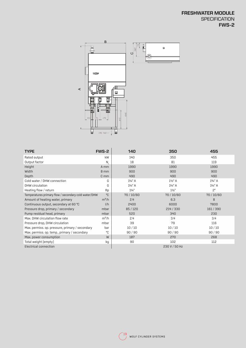
19WOLF CYLINDER SYSTEMS
A
C
B
TYPE FWS-2 140 350 455Rated output kW 140 350 455
Output factor NL
18 81 119
Height A mm 1990 1990 1990
Width B mm 900 900 900
Depth C mm 490 490 490
Cold water / DHW connection G 1¼" A 1½" A 1¾" A
DHW circulation G 1¼" A 1¼" A 1¼" A
Heating flow / return Rp 1¼" 1½" 2"
Temperatures primary flow / secondary cold water/DHW °C 70 / 10/60 70 / 10/60 70 / 10/60
Amount of heating water, primary m³/h 2.4 6.3 8
Continuous output, secondary at 60 °C l/h 2400 6000 7800
Pressure drop, primary / secondary mbar 85 / 120 214 / 330 161 / 390
Pump residual head, primary mbar 520 340 230
Max. DHW circulation flow rate m³/h 2.4 3.4 3.4
Pressure drop, DHW circulation mbar 39 79 116
Max. permiss. op. pressure, primary / secondary bar 10 / 10 10 / 10 10 / 10
Max. permiss. op. temp., primary / secondary °C 90 / 90 90 / 90 90 / 90
Max. power consumption W 187 270 268
Total weight (empty) kg 90 102 112
Electrical connection 230 V / 50 Hz
FRESHWATER MODULESPECIFICATION
FWS-2

20
DHW charging cylinder made from steel with two-layer enamel coating
Thermal insulation removable for easier
transport into the installation room
Cylinder interior protected against corrosion by a two-layer enamel
coating, plus a sacrificial magnesium anode for extra corrosion protection
Cold water/DHW connections and two G (male) 1¼" or 2" charging connections, 1" (fem.) DHW circulation, ½" (fem.) thermometer connection, two ½" (fem.) control or test connections
5 year statutory warranty on the floorstanding cylinder; 2 years on electrical and moving parts
BENEFITS OF THE WOLF FRESHWATER MODULEFWS-2
Low heat losses due to high grade thermal insulation,
100 mm thick
DHW outlet at the side
SEL DHW CHARGING CYLINDERS

21WOLF CYLINDER SYSTEMS
SEL
DHW charging cylinder for external heating by LS-2 cylinder charging module; made from steel with two-layer enamel coating
TYPE SEL 500 800 1000
Energy efficiency class1) C - -
Cylinder capacity litres 500 800 965
Standby heat loss kWh/24 h 2.72 2.62 3.05
Cold water connection A mm 85 122 122
Charging return / control connection B mm 310 323 323
Flange C mm 465 478 478
Anode D mm - 760 1106
DHW circulation / control connection E mm 894 900 1246
Charging flow F mm 1348 1450 1774
DHW connection / thermometer G mm 1478 1580 1904
Height excl. thermal insulation / air vent valve H mm - 1900 2250
Height incl. thermal insulation I mm 1806 2000 2350
Diameter excl. thermal insulation J mm - 790 790
Diameter incl. thermal insulation K mm 750 990 990
Height when tilted, incl. thermal insulation mm 1910 2232 2550
Height when tilted, excl. thermal insulation mm - 1960 2320
Internal flange diameter mm 120 120 120
DHW / cold water connection G (male) 1¼" 2" 2"
Charging flow / return G (male) 1¼" 2" 2"
DHW circulation G (fem.) 1" 1" 1"
Anode G (fem.) 1¼" 1¼" 1¼"
Control connection / thermometer G (fem.) ½" ½" ½"
Air vent valve G (fem.) 1¼" 2" 2"
Drain G (fem.) 1¼" 1¼" 1¼"
Max. operating pressure bar 10 10 10
Max. operating temperature °C 95 95 95
Weight kg 184 200 2701) Energy class according to Ecodesign Directive for cylinders ≤ 500 l
45°
HG
C
K
B
C
A
F
G
H
E
I
SEL-500
J
K
B
C
D
F
G
H
E
A
I
SEL-800/1000
WRS
LS
DHW CHARGING CYLINDERSSPECIFICATION
SEL
22
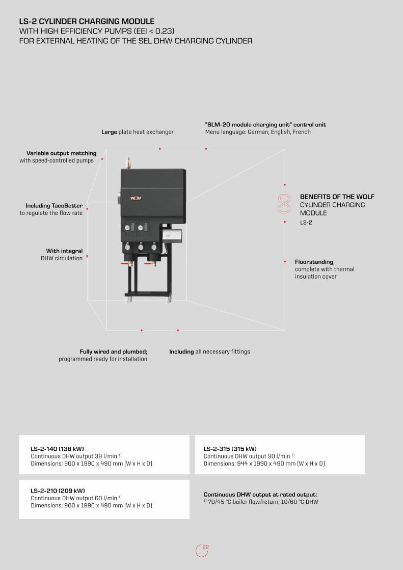
"SLM-20 module charging unit" control unit Menu language: German, English, French
Fully wired and plumbed; programmed ready for installation
Including all necessary fittings
Floorstanding, complete with thermal insulation cover
BENEFITS OF THE WOLF CYLINDER CHARGING MODULELS-2
Variable output matching with speed-controlled pumps
Large plate heat exchanger
LS-2-140 (138 kW) Continuous DHW output 39 l/min 1) Dimensions: 900 x 1990 x 490 mm (W x H x D)
LS-2-315 (315 kW) Continuous DHW output 90 l/min 1) Dimensions: 944 x 1990 x 490 mm (W x H x D)
LS-2-210 (209 kW) Continuous DHW output 60 l/min 1) Dimensions: 900 x 1990 x 490 mm (W x H x D)
Continuous DHW output at rated output: 1) 70/45 °C boiler flow/return; 10/60 °C DHW
LS-2 CYLINDER CHARGING MODULEWITH HIGH EFFICIENCY PUMPS (EEI < 0.23) FOR EXTERNAL HEATING OF THE SEL DHW CHARGING CYLINDER
Including TacoSetter to regulate the flow rate
With integral DHW circulation

23WOLF CYLINDER SYSTEMS
A
C
B
B
TYPE LS-2 140 210 315Rated output kW 140 210 315
Height A mm 1990 1990 1990
Width B mm 900 900 944
Depth C mm 490 490 490
Cylinder charging, flow / return G 1¼" A 1¼" A 1½" A
DHW circulation G 1¼" A 1¼" A 1¼" A
Heating flow / return Rp 1¼" 2" 2"
Primary FL / secondary RL/FL temperatures °C 70 / 10/60 70 / 10/60 70 / 10/60
Amount of heating water, primary m³/h 4.3 6.4 9.6
Continuous output, secondary at 60 °C l/h 2400 3600 5400
Pressure drop, primary / secondary mbar 124 / 175 154 / 211 297 / 177
Pump residual head, primary / secondary mbar 642 / 431 373 / 635 263 / 469
Max. DHW circulation flow rate m³/h 2.4 2.4 3.4
Pressure drop, DHW circulation mbar 32 65 78
Max. permiss. op. pressure, primary / secondary bar 10 / 10 10 / 10 10 / 10
Max. permiss. op. temp., primary / secondary °C 90 / 90 90 / 90 90 / 90
Max. power consumption W 365 445 587
Total weight (empty) kg 99 107 119
Electrical connection 230 V / 50 Hz
CYLINDER CHARGING MODULESPECIFICATION
LS-2

24
Large indirect coil surface areas ensure a short
heat-up time and a high continuous DHW output
Solar DHW cylinder made from steel with quality certificate, two-layer enamel coating and two smooth tube indirect coils
Low heat losses due to high grade rigid PUR foam or polyester fleece thermal insulation below the
foil jacket of the cylinder
Solar pump assembly can be fitted directly to the SEM-2 solar DHW cylinder
Connection for an electric booster heater
Optimised diameter/height ratio for good temperature stratification
Side flange for additional indirect coil and easy
maintenance
Cylinder interior and indirect coils protected against corrosion by a two-layer enamel coating and sacrificial magnesium anode
5 year statutory warranty on the floorstanding cylinder; 2 years on electrical and moving parts
BENEFITS OF THE WOLF SOLAR DHW CYLINDERSEM-1 / SEM-2
SEM-1 SEM-2
SOLAR DHW CYLINDERSSEM-1-500/750/1000SEM-2-300/400

25WOLF CYLINDER SYSTEMS
SEM-1 / SEM-2
Steel solar cylinder for DHW heating with two-layer enamel coating and two smooth tube indirect coils
WRS
ACCESSORIES
SOLAR PUMP ASSEMBLY
ELECTRIC BOOSTER HEATER 2 KW/230 V/50 HZ / 4.5 & 6 KW/400 V/50 HZ.Integral cylinder thermostat and high limit safety cut-out. Frost protection is assured. The cylinder water temperature can be adjusted either up to 60 °C or up to 80 °C.
CHARGING PUMP ¾" / 1"
THERMOMETER
IMPRESSED CURRENT ANODE
FLEXIBLE PIPE SET
SOLAR DHW CYLINDERSSEM-1-500/750/1000
SEM-2-300/400

26
TYPE SEM-1 - - 500 750 1000
SEM-2 300 400 - - -
Energy efficiency class1) C C C - -
Cylinder capacity litres 285 385 500 750 935
Standby heat loss kWh/24 h 1.92 2.41 2.44 2.73 3.2
Continuous cylinder output 80/60-10/45 °C (heating) kW - l/h 20 - 490 20 - 490 20 - 490 50 - 1200 50 - 1200
Output factor (heating) NL
2.3 4.8 6 13.5 18
Cold water connection A mm 90 55 99 220 220
Return, solar B mm 815 874 305 345 345
Cylinder sensor, solar C mm 506 416 586 603 603
Flow, solar D mm 815 874 865 920 975
Heating return E mm 974 987 985 1025 1340
Cylinder sensor, heating F mm 1154 1204 1160 1185 1500
DHW circulation G mm 1077 1092 1195 1290 1605
Heating flow H mm 1334 1335 1335 1475 1790
DHW connection I mm 1728 1586 1451 1590 1940
Flange (bottom) J mm 324 275 335 384 384
Electric booster heater K mm 887 915 949 970 1145
Thermometer L mm 1504 1416 1404 1460 1810
Total height M mm 1794 1651 1780 1850 2200
Diameter incl. thermal insulation N mm 600 701 850 1000 1000
Diameter excl. thermal insulation O mm - - - 800 800
Height when tilted, incl. thermal insulation mm 1898 1820 1935 2030 2350
Primary heating water bar/°C 10/110 10/110 10/110 10/110 10/110
Secondary DHW bar/°C 10/95 10/95 10/95 10/95 10/95
Internal flange diameter mm 114 114 114 114 114
Cold water connection G (male) 1" 1" 1" 1¼" 1¼"
Heating flow / return G (fem.) 1" 1" 1" 1¼" 1¼"
Solar flow / return G (male) ¾" ¾" 1"* 1¼"* 1¼"*
DHW circulation G (male) ¾" ¾" ¾" 1" 1"
DHW connection G (male) 1" 1" 1" 1¼" 1¼"
Electric booster heater G (fem.) 1½" 1½" 1½" 1½" 1½"
Thermometer G (fem.) ½" ½" ½" ½" ½"
Indirect coil surface area (heating) m² 1.0 1.2 1.0 1.5 1.5
Indirect coil surface area (solar) m² 1.6 2.2 1.8 2.1 2.4
Indirect coil content (heating) litres 5.8 7.0 6.1 9.2 9.2
Indirect coil content (solar) litres 9.4 13.0 11.5 13.5 14.5
Weight kg 130 159 182 290 350
*G (fem.)1) Energy class according to Ecodesign Directive for cylinders ≤ 500 l
SEM-1 SEM-2
A
F
E
H
I
G
N
J
C
B/D
K
L
M
B
A
C
D
F
E
H
I
J
K
L
M
N
O
G
SOLAR DHW CYLINDERSSPECIFICATIONSEM-1-500/750/1000SEM-2-300/400

27WOLF CYLINDER SYSTEMS
SE-2 DHW CYLINDERS
DHW cylinder made from steel with quality certificate, two-layer enamel coating and one smooth tube indirect coil
Cylinder interior and indirect coils protected against corrosion by a two-layer enamel coating
and a sacrificial magnesium anode (SE-2-750 with impressed current anode)
Large, low-lying internal indirect coil for short heat-up times and a high continuous DHW output
5 year statutory warranty on the floorstanding cylinder; 2 years on electrical and moving parts
BENEFITS OF THE WOLF DHW CYLINDERSE-2
Inspection and cleaning apertures for easy
maintenance
Low heat losses due to high grade rigid PUR foam thermal insulation below the foil jacket
of the cylinder
Optimised diameter/height ratio for
good temperature stratification
Connection for an electric booster heater

28
SE-2
DHW cylinder made from steel with two-layer enamel coating
WRS
DHW CYLINDERSSE-2-150/200/300/400/500/750
ACCESSORIES
ELECTRIC BOOSTER HEATER 2 KW/230 V/50 HZ / 4.5 & 6 KW/400 V/50 HZ.Integral cylinder thermostat and high limit safety cut-out. Frost protection is assured. The cylinder water temperature can be adjusted either up to 60 °C or up to 80 °C.
SP1 CONTROL UNIT FOR CHARGING PUMPS
CHARGING PUMP ¾" / 1"
THERMOMETER
IMPRESSED CURRENT ANODE
FLEXIBLE PIPE SET

29WOLF CYLINDER SYSTEMS
TYPE SE-2 150 200 300 400 500 750
Energy efficiency class1) B B C C C -
Cylinder capacity litres 140 195 285 380 485 750
Standby heat loss kWh/24 h 1.17 1.36 2.19 2.45 2.72 2.66
Continuous cylinder output 80/60-10/45 °C kW - l/h 28 - 700 28 - 700 40 - 1000 45 - 1100 53 - 1300 60 - 1500
Output factor NL
2.0 3.5 7.5 11.0 15.0 24.0
Cold water connection A mm 90 90 85 85 85 120
Heating return B mm 255 255 263 320 370 380
Cylinder sensor, heating C mm 603 720 898 960 1010 1156
DHW circulation D mm 665 800 983 1000 1095 860
Heating flow E mm 730 650 818 880 930 1025
DHW connection F mm 930 1194 1523 1525 1500 1580
Electric booster heater G mm 550 685 983 1000 1095 1080
Thermometer H mm 760 1024 1507 1521 1498 1485
Total height I mm 996 1260 1755 1800 1806 1982
Diameter incl. thermal insulation J mm 600 600 600 670 750 990
Diameter excl. thermal insulation K mm - - - - - 790
Flange (bottom) L mm 325 325 305 345 370 415
Height when tilted, incl. thermal insulation mm 1150 1350 1860 1925 1960 1940
Primary heating water bar/°C 10/110 10/110 10/110 10/110 10/110 10/110
Secondary DHW bar/°C 10/95 10/95 10/95 10/95 10/95 10/95
Internal flange diameter mm 110 110 120 120 120 178
Cold water connection G (male) 1" 1" 1" 1" 1" 1½"
Heating return G (fem.) 1" 1" 1" 1" 1" 1¼"
DHW circulation G (male) ¾" ¾" ¾" ¾" ¾" ¾"
Heating flow G (fem.) 1" 1" 1" 1" 1" 1¼"
DHW connection G (male) 1" 1" 1" 1" 1" 1½"
Electric booster heater G (fem.) 1½" 1½" 1½" 1½" 1½" 1½"
Thermometer G (fem.) ½" ½" ½" ½" ½" ½"
Indirect coil surface area m² 1.0 1.0 1.4 1.8 2.0 2.7
Indirect coil content litres 6.8 6.8 8.9 11.5 12.6 22.5
Weight kg 53 65 115 145 160 260
*G (male)1) Energy class according to Ecodesign Directive for cylinders ≤ 500 l
J
K
B
A
E
C
F
L
G
H
I
D
DHW CYLINDERSSE-2-150/200/300/400/500/750

30
NOTES

31WOLF CYLINDER SYSTEMS
NOTES
WOLF GMBH / P.O. BOX 1380 / D-84048 MAINBURG / TEL. +49.0.875174-0 / FAX +49.0.875174-1600 / www.WOLF.eu
Doc. no. 480631 GB 2017/08
Dealer address