TECHNICAL DATA - Viking Group · PDF fileTECHNICAL DATA June 3, 2011 45a ESFR CoLD SToRAgE...
10
TECHNICAL DATA June 3, 2011 45a ESFR COLD STORAGE SYSTEM The Viking Corporation, 210 N Industrial Park Drive, Hastings MI 49058 Telephone: 269-945-9501 Technical Services: 877-384-5464 Fax: 269-818-1680 Email: [email protected] Replaces page 45a-j, dated April 1, 2011. (Revised section 4.G.) Form No. F_033004 1. SYSTEM DESCRIPTION The Viking ESFR Pre-Primed Single Interlocked Preaction Cold Storage System is fixed fire protection for refrigerated or cold ware- house storage. This system is also appropriate for unheated storage applications in areas subject to freezing. The piping system is filled with pressurized propylene glycol and water solution maintained from a pressure pump system that controls and maintains the desired solution pressure. This is a pre-primed preaction system with electric release that utilizes a deluge valve with conventional and electric release trims and listed release control panel with proper detection system. The riser consists of two Viking Easy Riser ® Swing Check Valves, one with trim for preprimed preaction system and the second with by-pass trim to moderate the antifreeze thermal transfer in the system from the water supply. The sprinklers used in this system are closed heat-sensitive Viking ESFR K25.2 VK510 Pendent Sprinklers having an ordinary tem- perature rating of 165 °F (74 °C). With this system, ceiling-only sprinklers are required and no in-rack sprinklers are needed. Single row, double row, and multiple row rack storage is required and sprinklers shall be located in accordance with applicable Viking Techni- cal Data and the latest recognized storage installation rules of NFPA or the Authority Having Jurisdiction (AHJ). Open rack storage is required, and sprinklers shall be located in accordance with applicable Viking technical data (refer to the latest issue of sprinkler data page 124a-f) and the latest recognized storage installation rules of NFPA or the Authority Having Jurisdiction (AHJ). 2. SYSTEM OPERATION Upon operation of the detection system, the deluge valve opens prior to sprinkler operation and pressurizes the sprinkler piping to the desired discharge pressure. Upon operation of the sprinkler(s), the pressurized propylene glycol/water solution is distributed from the sprinkler. Water from the supply system pushes out the propylene glycol/water solution at a very rapid rate due to the sprinkler orifice size and design pressures. The limited system volume ensures that 100% water will flow from the sprinklers at an appropriate stage of fire development. Upon water replacement of propylene glycol/water solution in the system, 100% water is distributed over the specific area to control or suppress the fire. The CS-1 Tank and Pump System is designed to maintain supervisory system static pressure in the sprinkler piping using antifreeze and water premix. As the deluge valve operates, an alarm pressure switch is used to send a signal to the CS-1 system control to shut off the flow of antifreeze from the reservoir. Upon operation of the detection system, the deluge valve opens and pressurizes the sys- tem to desired starting discharge pressure. An alarm is activated due to water flow from the alarm pressure switch on the conventional trim. When the ESFR Sprinkler(s) operate, the system is already pressurized and will discharge the antifreeze solution followed by water. Typically, only those sprinklers above or adjacent to the fire operate, minimizing water damage and contamination. Other anti- freeze systems within the warehouse would not typically be activated. In the event of a broken sprinkler or sprinkler pipe without a fire condition, the deluge valve will hold back the water supply and only an- tifreeze will be drained from the sprinkler or broken pipe. This will prevent large amounts of water from being discharged and possible contamination of the antifreeze left in the system that could cause undesired freezing in the piping. A pressure supervisory switch on the antifreeze system located at the primary Easy Riser ® Check Valve adjacent to the deluge valve will provide an alarm of low-pres- sure condition. The antifreeze supply from the CS-1 Pump must be manually shut off in this condition at the riser supply point. In the event of a fire, the system pressure switch that controls the system solenoid valve is wired through the alarm switch located on the deluge valve and to the CS-1 panel. In this case, the CS-1 system solenoid valve is restricted from opening for the riser that is flowing to the fire area and stops the flow of antifreeze to the discharging system. 3. APPLICATION This system shall be designed by qualified fire protection technicians, in conjunction with requirements of the Authorities Having Juris- diction. Viking ESFR Cold Storage Systems are designed to meet the requirements described in Viking technical data for ESFR K25.2 Sprinkler VK510 for use with 35% or 50% propylene glycol and water solution, and the standards of NFPA 13 or other organizations, and also with the provisions of governmental codes, ordinances, and standards where applicable. This system shall meet all require- ments of ESFR installations except where specified in this data sheet. This system can be considered a wet system due to the system being filled with the approved antifreeze solution, and operation of the detection and preaction system will provide water supply and pressurized solution at the sprinkler upon operation. In order to effectively apply 100% water as rapidly as possible, the system size must be limited in volume. The system uses either a 35% or 50% (depending on the minimum temperature in the area being protected) by volume mixture of propylene glycol and water premix solution. The propylene glycol and water mixture cools and adds wetting ability to control the fire until water is applied to sup- press the fire. 4. SYSTEM DESIGN A. HYDRAULIC CALCULATIONS The area of coverage for a single system is dependent upon the volume of the system required to cover the area being protected. The hydraulic calculations are necessary in order to properly size the system piping.
Transcript of TECHNICAL DATA - Viking Group · PDF fileTECHNICAL DATA June 3, 2011 45a ESFR CoLD SToRAgE...

TECHNICAL DATA
June 3, 2011 45a
ESFR CoLD SToRAgE SySTEm
The Viking Corporation, 210 N Industrial Park Drive, Hastings mI 49058Telephone: 269-945-9501 Technical Services: 877-384-5464 Fax: 269-818-1680 Email: [email protected]
Replaces page 45a-j, dated April 1, 2011. (Revised section 4.G.)
Form No. F_033004
1. SySTEm DESCRIPTIoNThe Viking ESFR Pre-Primed Single Interlocked Preaction Cold Storage System is fixed fire protection for refrigerated or cold ware-house storage. This system is also appropriate for unheated storage applications in areas subject to freezing. The piping system is filled with pressurized propylene glycol and water solution maintained from a pressure pump system that controls and maintains the desired solution pressure. This is a pre-primed preaction system with electric release that utilizes a deluge valve with conventional and electric release trims and listed release control panel with proper detection system. The riser consists of two Viking Easy Riser® Swing Check Valves, one with trim for preprimed preaction system and the second with by-pass trim to moderate the antifreeze thermal transfer in the system from the water supply.The sprinklers used in this system are closed heat-sensitive Viking ESFR K25.2 VK510 Pendent Sprinklers having an ordinary tem-perature rating of 165 °F (74 °C). With this system, ceiling-only sprinklers are required and no in-rack sprinklers are needed. Single row, double row, and multiple row rack storage is required and sprinklers shall be located in accordance with applicable Viking Techni-cal Data and the latest recognized storage installation rules of NFPA or the Authority Having Jurisdiction (AHJ). Open rack storage is required, and sprinklers shall be located in accordance with applicable Viking technical data (refer to the latest issue of sprinkler data page 124a-f) and the latest recognized storage installation rules of NFPA or the Authority Having Jurisdiction (AHJ).
2. SySTEm oPERATIoNUpon operation of the detection system, the deluge valve opens prior to sprinkler operation and pressurizes the sprinkler piping to the desired discharge pressure. Upon operation of the sprinkler(s), the pressurized propylene glycol/water solution is distributed from the sprinkler. Water from the supply system pushes out the propylene glycol/water solution at a very rapid rate due to the sprinkler orifice size and design pressures. The limited system volume ensures that 100% water will flow from the sprinklers at an appropriate stage of fire development. Upon water replacement of propylene glycol/water solution in the system, 100% water is distributed over the specific area to control or suppress the fire. The CS-1 Tank and Pump System is designed to maintain supervisory system static pressure in the sprinkler piping using antifreeze and water premix. As the deluge valve operates, an alarm pressure switch is used to send a signal to the CS-1 system control to shut off the flow of antifreeze from the reservoir. Upon operation of the detection system, the deluge valve opens and pressurizes the sys-tem to desired starting discharge pressure. An alarm is activated due to water flow from the alarm pressure switch on the conventional trim. When the ESFR Sprinkler(s) operate, the system is already pressurized and will discharge the antifreeze solution followed by water. Typically, only those sprinklers above or adjacent to the fire operate, minimizing water damage and contamination. Other anti-freeze systems within the warehouse would not typically be activated.In the event of a broken sprinkler or sprinkler pipe without a fire condition, the deluge valve will hold back the water supply and only an-tifreeze will be drained from the sprinkler or broken pipe. This will prevent large amounts of water from being discharged and possible contamination of the antifreeze left in the system that could cause undesired freezing in the piping. A pressure supervisory switch on the antifreeze system located at the primary Easy Riser® Check Valve adjacent to the deluge valve will provide an alarm of low-pres-sure condition. The antifreeze supply from the CS-1 Pump must be manually shut off in this condition at the riser supply point.In the event of a fire, the system pressure switch that controls the system solenoid valve is wired through the alarm switch located on the deluge valve and to the CS-1 panel. In this case, the CS-1 system solenoid valve is restricted from opening for the riser that is flowing to the fire area and stops the flow of antifreeze to the discharging system.
3. APPLICATIoN This system shall be designed by qualified fire protection technicians, in conjunction with requirements of the Authorities Having Juris-diction. Viking ESFR Cold Storage Systems are designed to meet the requirements described in Viking technical data for ESFR K25.2 Sprinkler VK510 for use with 35% or 50% propylene glycol and water solution, and the standards of NFPA 13 or other organizations, and also with the provisions of governmental codes, ordinances, and standards where applicable. This system shall meet all require-ments of ESFR installations except where specified in this data sheet. This system can be considered a wet system due to the system being filled with the approved antifreeze solution, and operation of the detection and preaction system will provide water supply and pressurized solution at the sprinkler upon operation.In order to effectively apply 100% water as rapidly as possible, the system size must be limited in volume. The system uses either a 35% or 50% (depending on the minimum temperature in the area being protected) by volume mixture of propylene glycol and water premix solution. The propylene glycol and water mixture cools and adds wetting ability to control the fire until water is applied to sup-press the fire.
4. SySTEm DESIgNA. HyDRAULIC CALCULATIoNS
The area of coverage for a single system is dependent upon the volume of the system required to cover the area being protected. The hydraulic calculations are necessary in order to properly size the system piping.
TECHNICAL DATA
June 3, 201145b
ESFR CoLD SToRAgE SySTEm
The Viking Corporation, 210 N Industrial Park Drive, Hastings mI 49058Telephone: 269-945-9501 Technical Services: 877-384-5464 Fax: 269-818-1680 Email: [email protected]
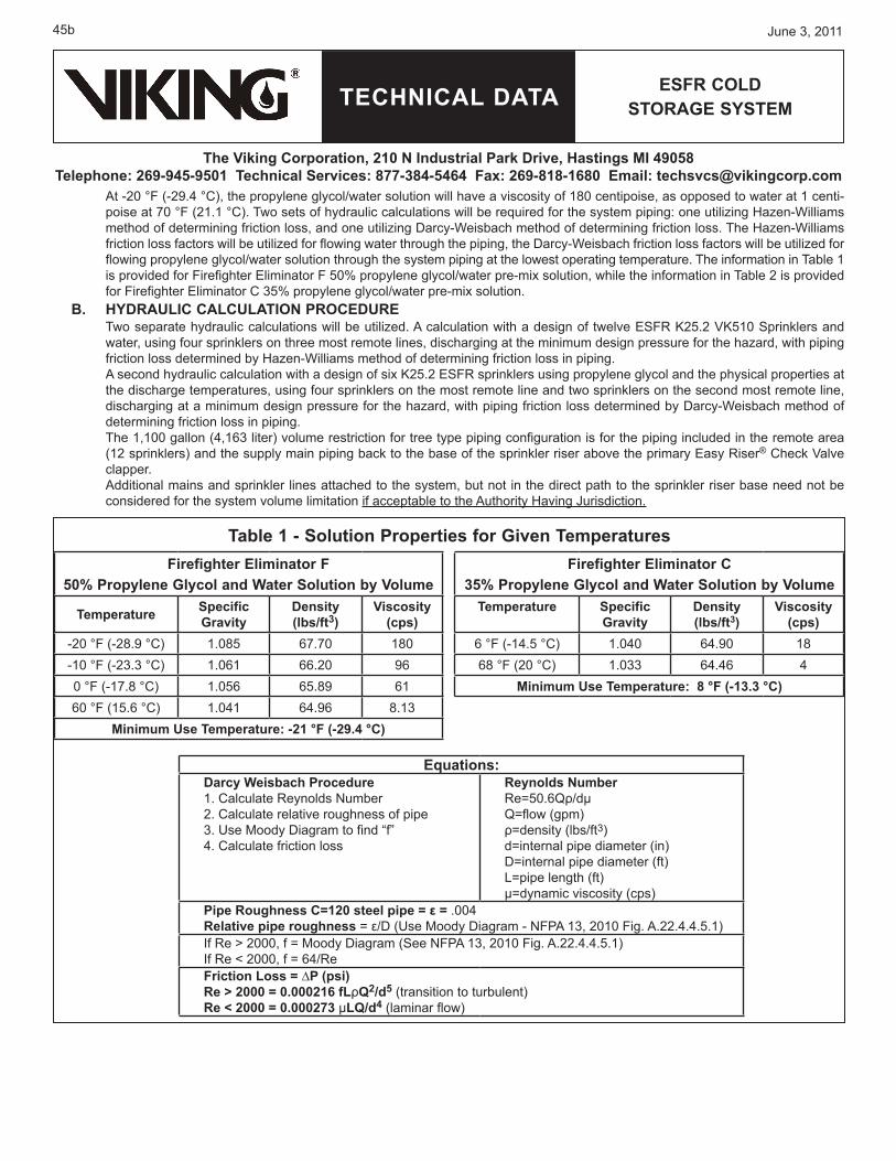
At -20 °F (-29.4 °C), the propylene glycol/water solution will have a viscosity of 180 centipoise, as opposed to water at 1 centi-poise at 70 °F (21.1 °C). Two sets of hydraulic calculations will be required for the system piping: one utilizing Hazen-Williams method of determining friction loss, and one utilizing Darcy-Weisbach method of determining friction loss. The Hazen-Williams friction loss factors will be utilized for flowing water through the piping, the Darcy-Weisbach friction loss factors will be utilized for flowing propylene glycol/water solution through the system piping at the lowest operating temperature. The information in Table 1 is provided for Firefighter Eliminator F 50% propylene glycol/water pre-mix solution, while the information in Table 2 is provided for Firefighter Eliminator C 35% propylene glycol/water pre-mix solution.
B. HyDRAULIC CALCULATIoN PRoCEDURETwo separate hydraulic calculations will be utilized. A calculation with a design of twelve ESFR K25.2 VK510 Sprinklers and water, using four sprinklers on three most remote lines, discharging at the minimum design pressure for the hazard, with piping friction loss determined by Hazen-Williams method of determining friction loss in piping.A second hydraulic calculation with a design of six K25.2 ESFR sprinklers using propylene glycol and the physical properties at the discharge temperatures, using four sprinklers on the most remote line and two sprinklers on the second most remote line, discharging at a minimum design pressure for the hazard, with piping friction loss determined by Darcy-Weisbach method of determining friction loss in piping.The 1,100 gallon (4,163 liter) volume restriction for tree type piping configuration is for the piping included in the remote area (12 sprinklers) and the supply main piping back to the base of the sprinkler riser above the primary Easy Riser® Check Valve clapper.Additional mains and sprinkler lines attached to the system, but not in the direct path to the sprinkler riser base need not be considered for the system volume limitation if acceptable to the Authority Having Jurisdiction.
Firefighter Eliminator F 50% Propylene glycol and Water Solution by Volume
Temperature Specific gravity
Density(lbs/ft3)
Viscosity (cps)
-20 °F (-28.9 °C) 1.085 67.70 180-10 °F (-23.3 °C) 1.061 66.20 960 °F (-17.8 °C) 1.056 65.89 6160 °F (15.6 °C) 1.041 64.96 8.13
minimum Use Temperature: -21 °F (-29.4 °C)
Firefighter Eliminator C 35% Propylene glycol and Water Solution by Volume
Temperature Specific gravity
Density(lbs/ft3)
Viscosity (cps)
6 °F (-14.5 °C) 1.040 64.90 1868 °F (20 °C) 1.033 64.46 4
minimum Use Temperature: 8 °F (-13.3 °C)
Table 1 - Solution Properties for given Temperatures
Equations:Darcy Weisbach Procedure1. Calculate Reynolds Number2. Calculate relative roughness of pipe3. Use Moody Diagram to find “f”4. Calculate friction loss
Reynolds NumberRe=50.6Qρ/dμQ=flow (gpm)ρ=density (lbs/ft3)d=internal pipe diameter (in)D=internal pipe diameter (ft)L=pipe length (ft)µ=dynamic viscosity (cps)
Pipe Roughness C=120 steel pipe = ε = .004Relative pipe roughness = ε/D (Use Moody Diagram - NFPA 13, 2010 Fig. A.22.4.4.5.1)If Re > 2000, f = Moody Diagram (See NFPA 13, 2010 Fig. A.22.4.4.5.1) If Re < 2000, f = 64/ReFriction Loss = ∆P (psi)Re > 2000 = 0.000216 fLρQ2/d5 (transition to turbulent)Re < 2000 = 0.000273 µLQ/d4 (laminar flow)

TECHNICAL DATA
June 3, 2011 45c
ESFR CoLD SToRAgE SySTEm
The Viking Corporation, 210 N Industrial Park Drive, Hastings mI 49058Telephone: 269-945-9501 Technical Services: 877-384-5464 Fax: 269-818-1680 Email: [email protected]
C. ESFR CoLD SToRAgE SySTEmThe discharge pressure for all sprinklers flowing must maintain at a minimum of the required design. For tree systems utilizing this system, the branch lines or supply mains should not be looped together as done in some dry pipe and preaction systems. The actual propylene glycol solution requirement for the system is determined by adding all the system piping volume together. In regards to all other aspects of this system, installation requirements apply as described. All NFPA 13 installation criteria and AHJ requirements apply to installation of the Viking ESFR Cold Storage System with the following exceptions:
Commodity limited to Class II or less (limited to wood pallets).Maximum ceiling height to bottom of inside upper deck is 40 ft. (12.2 m) with a maximum storage height of 35 ft. (10.7 m) and a minimum sprinkler discharge pressure of 40 PSI (2.8 bar). oR:Maximum ceiling height to bottom of inside upper deck is 45 ft-3 in. (13.8 m) with maximum storage height of 40 ft. (12.2 m) and a minimum sprinkler discharge pressure of 60 PSI (4.14 bar).Where the minimum temperature in the area being protected is 8 °F (-13.3 °C) or above, 35% percent by volume of propylene glycol factory premixed with water must be used. Viking requires Firefighter Eliminator C premix 35% propylene glycol/water mixture with a freeze temperature rating (freeze point) of 2.4 °F (-16.4 °C). oR:Where the minimum temperature in the area being protected is between 8 °F (-13.3 °C) and -21 °F (-29.4 °C), the percentage by volume of propylene glycol must be 50%, factory premixed with water for antifreeze solution. Viking requires Firefighter Eliminator F type 50% propylene glycol/water mixture, with a freeze temperature rating (freeze point) of -26 °F (-32.2 °C). Minimum ambient temperature is -21 °F (-29.4 °C). NOTE: The minimum temperature is NOT an average in the freezer, but is the lowest temperature for the system.Maximum system volume is 1,100 gallons (4,163 liters). Refer to calculation to determine volume.Detection System shall be capable of operation prior to or equal to an ESFR Sprinkler having an RTI (Response Time Index) of 50 or less. No linear detection shall be allowed. This limits the system to low temp spot heat, beam smoke or air sample type smoke system or equal.Use ordinary temperature rated 165 °F (74 °C) Viking ESFR K25.2 Sprinkler VK510. Exception: Intermediate temperature rated 205 °F (96 °C) Viking ESFR VK510 K25.2 Sprinklers that are intended for installation in close proximity to heat sources may be applied only as referenced in NFPA 13.The piping system must be pitched for drainage of the system after operation. For refrigerated area systems, the piping system shall be pitched to drain complete system toward the riser and Easy Riser® Check Valve with branch lines at ½” per 10 ft. (4 mm/m) and mains at ½” per 10 ft. (4 mm/m) run of pipe. For systems in unheated areas subject to freezing, branch lines shall be pitched at ½” per 10 ft. (4 mm/m) and mains at ¼” per 10 ft. (2 mm/m) run of pipe. The system must be designed so maximum operating pressure of the system does not exceed 175 PSI (12 bar) at the sprinkler, including test pressures of pumps at zero flow.For specific limitations on Expansion of Antifreeze, see the Automatic Pressure Control System, data pages 47a-c.For specific limitations on the CS-1 Pump and Tank, see data pages 51a-j.For specific limitations on Propylene Glycol Solution, see data pages 49a-b and 50a-b.
For system configuration, see Figure 1. D. PIPINg SySTEm To SPRINKLERS
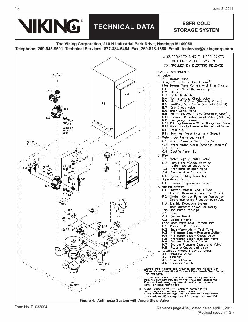
Piping configurations vary. There are side or end feeds, offset feeds, and center feeds. Many times the configuration of the system piping is dictated by building features or by hydraulic calculations. The deluge valve and trim system, system check valves, along with all antifreeze supply piping (see Figure 3 or 4 and data page 48a-d) must be installed in a heated area that is maintained at or above 40 °F (4 °C). Insulating the fire sprinkler riser will be required to eliminate condensation and frost from developing on the piping in the heated area. Insulate the riser main from the freezer wall to the isolation check valve. If the primary system check valve is close enough to isolation check valve and freezer separation wall to cause freezing of water and condensation on piping below the check valve, then a listed heat trace heating system may be required for the riser piping above and below the primary check valve that will maintain a temperature under the insulation to eliminate condensation and maintain internal temperature of solution above freezing for air below the primary check valve. Due to difficulty in servicing and insulating the check valve, it is recommended to install the deluge and check valve near floor level at the base of the main riser in the heated area allowing approximately 1 to 2 ft between the outlet of deluge valve and inlet of the primary Easy Riser® Check Valve. Maintain the longest separation as possible but at least 5 to 10 ft (1.5 to 3 m) of pipe from the primary Easy Riser® Check Valve to the isolation check valve that is between the freezer wall and the primary check valve. This will reduce the cold thermal transfer of propylene glycol solution in the system piping to the vertical system riser and minimize frosting on the system riser.Air vent valves or manual bleed valves must be installed at the highest and most remote points on the piping system in order to vent out all air during fill of the 35% or 50% premix of propylene glycol/water solution in the system. Additional vent or bleed valves shall be installed on the end of each branch line piping to ensure air is vented from the system. This is required in order to eliminate compressible gas (air) from the system when setting supervisory pressure from the antifreeze CS-1 pump system. Also, the manual vent valves may be used for multiple sample points of the system for quality testing of the antifreeze solution.
••
•
•
•
•
••
•
•
•
•••
TECHNICAL DATA
June 3, 201145d
ESFR CoLD SToRAgE SySTEm
The Viking Corporation, 210 N Industrial Park Drive, Hastings mI 49058Telephone: 269-945-9501 Technical Services: 877-384-5464 Fax: 269-818-1680 Email: [email protected]
The Viking Model AV-1 Automatic Air/Vent Valve is recommended for this use. It automatically vents air during fill and breaks the vacuum for faster drainage of the system when performing maintenance or draining the system after operation.
E. THE mAIN DRAIN The main drain valve will be used to drain the system piping downstream of the Easy Riser® Check Valves. The main drain outlet should be directed to an appropriate location and the drain valve shall be installed at an accessible level so it can be operated from floor level. The main drain valves from the isolation check and primary check valves shall be installed at an accessible level, as the solution will be trapped in the drop leg to the drain valve and will not affect the total calculation for the system. As the cold antifreeze from the freezer area will emit cold thermal transfer, it will be required to insulate the drain pipe to prevent frosting.Propylene glycol/water solutions are designed to be installed on systems supplied by potable water supplies. Local authorities should be consulted prior to draining system to storm sewers or to natural drainage areas. In the main drain line between the valve and Easy Riser® Check Valves inlet, a tee is provided on the check valve trim with a 1” NPT connection for supply and maintenance of the antifreeze solution to the system above the primary Easy Riser® Check Valve.
F. RECLAIm TANKAn atmospheric storage tank is to be installed for the system(s) that is of adequate capacity of the largest system volume in-stalled. The tank shall be utilized as a reclaim tank for the propylene glycol solution in the system piping when the system(s) are drained for system service and for discharge of propylene glycol solution if system pressure exceeds 175 PSI (12 bar) at the sprinklers.
g. SoLUTIoN TEST VALVES Multiple propylene glycol/water solution test valves are to be installed on the system piping for semi-annual testing with a refrac-tometer to detect the concentration of antifreeze solution and effectiveness against freezing. When draining sample antifreeze solution from the system, be sure to shut off the system control valve directly upstream of the deluge valve so that water doesn’t enter the system. Sampling shall be taken from multiple points within the freezer system. The testing stated in this section is more restrictive than the required test frequency indicated in NFPA 25. Solution test valves should be located in several areas of the system piping as follows:
The most practical location immediately downstream of the primary Easy Riser® Check Valve.The most remote location from the Easy Riser® Check Valve.One valve located at the end of 50% of the line piping directly on the AV-1 Air/Vent Valve Assembly.A test valve shall be located at the end of the nearest line on the tree system and the last line on the tree system.
If the propylene glycol/water solution becomes diluted or does not pass the refractometer test, the entire system is to be drained; all sections of trapped piping are to be drained. Five percent (5%) of the pendent ESFR sprinklers are to be removed and in-spected for frozen solution. If any of the pendent ESFR sprinklers are found with frozen solution, then all the pendent ESFR sprinklers are to be removed and replaced with new Viking K25.2 Pendent ESFR VK510 Sprinklers prior to re-charging the sys-tem with new 35% or 50% premix propylene glycol/water solution. (Refer to the system service schedule for additional solution tests.)Ensure that the CS-1 pump antifreeze supply control system is returned to the fully pressurized state once fluid sampling is com-pleted. After the CS-1 pump has restored the antifreeze solution pressure, ensure that the water supply control valve is returned to the fully open position once fluid sampling is completed.
H. RE-CHARgINg SySTEm PIPINg WITH 35% oR 50% PREmIX PRoPyLENE gLyCoL/WATER SoLUTIoN A suitable portable pump can be utilized to fill the system. (The CS-1 pump can be used for filling the system initially at 15 GPM (56 l/min) to 100 ft. head pressure or system static pressure, however, it is a less efficient pump for filling the system because of the duration of time required to do so. The CS-1 pump is to be utilized to bring the antifreeze solution to supervisory pressure [normally recommended 50 PSI (3.45 bar) and is designed to maintain system supervisory pressure once the system is initially filled. Also, repeat air bleed from the system as described above. If using the Viking Model AV-1 Air/Vent Valve Assembly, the air will automatically be vented during the fill cycle.
I. EXPANSIoN oF ANTIFREEZE IN THE SySTEmIn a freezer system, the atmospheric temperature is typically controlled at a pre-determined desired temperature year round. The most likely time over-pressurization of the system might occur due to temperature fluctuation is in a warm-up mode of the freezer. See Automatic Pressure Control data page 47a-c for Installation and Start-up Instructions.
J. CS-1 PUmPThe purpose the antifreeze pressure pump is to lock in a supervisory pressure in the system and eliminate air for proper perfor-mance of the system. The CS-1 pump utilized on the ESFR Cold Storage System provides a static pressure on the propylene glycol/water solution in the system by taking suction from an atmospheric storage tank with premix propylene glycol and water solution and discharging to the downstream or system side of the primary Easy Riser® Check Valve clapper. See CS-1 Pump and Tank data 51a-j for Installation, Start-up and Maintenance of Pump Package.
••••

TECHNICAL DATA
June 3, 2011 45e
ESFR CoLD SToRAgE SySTEm
The Viking Corporation, 210 N Industrial Park Drive, Hastings mI 49058Telephone: 269-945-9501 Technical Services: 877-384-5464 Fax: 269-818-1680 Email: [email protected]
K. PRoPyLENE gLyCoL AND WATER SoLUTIoN PREmIXPremix 35% or 50% propylene glycol and water solution that is certified by the manufacturer or a third-party agency is to be installed in the system piping. Field mixing of propylene glycol and site water is strictly prohibited as the control of the mixture cannot be assured. See Firefighter Eliminator data pages 49a-b or 50a-b for more detailed information regarding solution.
L. RISER SySTEmThe arrangement of the riser system shall include a Viking Model E or F Deluge Valve with Conventional Trim, Electric Release, a primary Easy Riser® Check Valve including Cold Trim, an isolation Easy Riser® Check Valve including cold storage by-pass trim. The system must include a supervised system control valve upstream of the deluge valve and a supervised system isolation valve downstream of the isolation check valve. The downstream system isolation valve is required to facilitate maintenance of the system and isolation of antifreeze solution during maintenance and testing. Pressure relief valve must be selected based on height position of the valve and static pressure to restrict pressure at the sprin-kler to its rated pressure. The pressure relief valve shall be selected so as to not open at the flowing pressure. The relief valve shall be ordered separately. Calculate the differential height and specific gravity of antifreeze at the operating temperature of the freezer and size the PRV relief pressure accordingly.The alarm line of the deluge valve shall be attached to an alarm pressure switch (and mechanical water motor alarm, if required) that activates an alarm due to activation of the system. An additional supervisory pressure switch on the primary check valve system side is required in order to provide a low pressure alarm in the case of antifreeze pressure loss due to sprinkler operation without a fire condition. In this case the antifreeze supply must be manually shut off to the low-pressure riser. The isolation valve is located on the antifreeze inlet line of the riser primary check valve.
m. ALARm TEST CoNNECTIoNAn alarm test connection is provided on the deluge valve trim. When testing the alarm, the downstream isolation valve and an-tifreeze isolation valve must be shut before opening the test valve. This is a precaution in case the deluge valve would inadver-tently operate due to problems in the trim components and cause water to enter the system causing possible contamination of antifreeze. After testing of the alarm, restore the control valves to their normal operating position and open the antifreeze supply valve.
N. FLoW TEST VALVEAnnual flow tests are required for every sprinkler system. When performing annual water flow tests for the ESFR Pre-Primed Single Interlocked Preaction Cold Storage System, you will utilize the main drain of the isolation check valve. This will allow the primary check valve clapper to open also. First, close the supervised system isolation valve downstream of the isolation check valve. Close the antifreeze inlet ball valve. The deluge valve must be operated (opened) to perform the flow test. Close the prime line valve and open the emergency manual release valve. Make sure the diversion drain valve is open to flow water to a drain area or the recovery tank as desired. Note: If antifreeze is stored in the recovery tank, do not allow water to enter, or contamina-tion of solution will occur. Record the water supply pressure on the water supply pressure gauge upstream of the deluge valve.Open the main drain on the downstream isolation check valve fully. This will allow water to flow through the deluge valve and both the primary and isolation check valves. Once the pressure gauge has settled to flowing pressure, record the pressure on the water supply pressure gauge upstream of the deluge valve.After the water flow test is completed, close the water supply control valve upstream of the deluge valve, drain all the water located between the primary and isolation check valves. Then drain all water from between the deluge valve and the primary check valve using the auxiliary drain on the deluge valve trim. Close the main drain and auxiliary drain once water is completely drained. Open the antifreeze supply isolation valve. The CS-1 pump will supply propylene glycol/water solution from the mainte-nance solution supply tank. The CS-1 pump will stop running when the pressure in the section of piping is 50 PSI (3.45 bar) or the set pressure of the system pressure switch. Ensure there is no trapped air in the piping between check valves by bleeding through the main drain valve of the isolation check valve. After system pressure is built, the CS-1 pump will stop running. Open the down stream system isolation valve, when system antifreeze pressure is at desired pressure and the CS-1 pump stops. Now, prime the deluge valve by opening the prime supply valve and watch for pressure to build in the prime chamber of the deluge valve. Now, open the system shut-off valve upstream of the deluge valve. Any supervisory alarm switches silenced for system maintenance must be re-set. The system is now in service.
o. gENERAL PIPINg AND mATERIAL REQUIREmENTSIn order to prevent leaks and preserve the antifreeze solution, it is imperative that grooved pipe ends are smooth, round, and free of burrs, flat spots, and weld seam imperfections. Also, pipes should be capped to prevent contaminant during shipping, storage, etc. Antifreeze solution is very lubrise and difficult to seal compared to plain water and initial care in pipe connections will minimize leaks at start-up. Prefabricated pipe should be capped during shipping and staging prior to installation.Prefabricated pipe should be capped during shipping and staging prior to installation.If grooved couplings are utilized in the system piping installation, “flush seal” gaskets, low temperature EPDM rubber and lube are required. Pooling of propylene glycol system shall be eliminated. Vent valves shall be minimum ½” ball valves with ½” plug. Vent valves can double as solution test points as well; the Viking Model AV-1 Air/Vent Valve is recommended, as it includes strainer and test connection for automatic venting during fill and drain of the system. Material installed on the system shall be compatible with propylene glycol solution. A re-claim tank with adequate capacity of the largest system(s) shall be located near the system riser(s). System drain piping shall be arranged to discharge to the re-claim tank.

TECHNICAL DATA
June 3, 201145f
ESFR CoLD SToRAgE SySTEm
The Viking Corporation, 210 N Industrial Park Drive, Hastings mI 49058Telephone: 269-945-9501 Technical Services: 877-384-5464 Fax: 269-818-1680 Email: [email protected]
Verify that any gasket materials used in couplings, etc. are compatible with the antifreeze solution. Refer to the antifreeze solution technical data page.
gaskets: Grade “E” EPDM. NSF-61 Certified. -40 °F to 230 °F (service temperature range) (-40 °C to 110 °C) Recommended for water service, diluted acids, alkalys solutions, oil-free air and many chemical services. Xtremeä Lubricant is required for freezer applications.Lubricant: GRUVLOK Xtreme Lubricant has been developed for use with Gruvlok couplings in services where improved lubrication is beneficial. This lubricant has an operating temperature range from -65 °F to 400 °F (-54 °C to 204 °C), well°F to 400 °F (-54 °C to 204 °C), well to 400 °F (-54 °C to 204 °C), well exceeding the temperature range of Gruvlok gaskets. This lubricant is waterproof, thereby eliminating water wash-out and it will not dry out in the absence of water. There are five primary applications. Since it is formulated from a non-hydrocarbon base, it can be used with EPDM, Nitrile and Fluoroelastomer gasket materials. It is not to be used with silicone gaskets.
5. SERVICE PRoCEDURESA. DRAIN-DoWN oF THE INDIVIDUAL SySTEm (if system operation has occurred):
After system trip and sprinkler(s) have operated and water has entered the system, the complete system must be drained down immediately and solution within the piping system disposed of.All sprinklers are pendent type and must be removed and replaced with new sprinklers. This is due to possible collection of water at each sprinkler and creation of a small ice plug in each sprinkler.If using the Viking Model AV-1 Air/Vent Valve Assembly, the device also breaks a vacuum in the piping system and provides faster and more complete drainage of the system piping.
B. TAKINg THE SySTEm oUT oF SERVICEClose the water supply control valve to the riser being serviced.Close the antifreeze supply valve to the riser being serviced.If the system is being serviced, then the solution in the system can be drained into clean containers or reclaim tank and reused as long as water has not entered the systems. Solution should be checked at various points while draining for proper refractometer readings to verify freeze-protection properties.Open vent/bleed valves at high points of the system, or, if the AV-1 Vent Valve is applied, it will automatically open.Open the main drain and collect solution in clean containers or recovery tank for re-use in the system.After the system is completely drained from the main drain, open any low-point drains to remove the remaining solution from the system
C. PLACINg THE SySTEm IN SERVICE (after it has been completely drained):Close the main drain valve on the riser.Connect the propylene glycol/water solution fill pump (NOT the CS-1 Pump) to the connection located on the main drain assembly.Close the main drain valve, vent/bleed valves, and low-point drains if opened. Ensure there are no openings on system piping.Fill system with Firefighter Eliminator C or Eliminator F Propylene Glycol/Water Solution. While filling, periodically open the manual vent/bleed valves or allow the Model AV-1 Vent Valve to automatically open on system piping to ensure air is elimi-nated from system piping. Slow fill is recommended to minimize the entrainment of air.Fill and pressurize system piping to 50 PSI (3.45 bar) minimum using the CS-1 Pump System to provide the final set system pressure.Check for trapped air by cracking open vent/bleed valves or observe the AV-1 Vent Valve. Ensure all trapped air is eliminated from the system.After system pressure is attained, the water supply control valve upstream of the deluge valve can be opened.
•
•
1.
2.
3.
1.2.3.
4.5.6.
1.2.
3.
4.
5.
6.
7.

TECHNICAL DATA
June 3, 2011 45g
ESFR CoLD SToRAgE SySTEm
The Viking Corporation, 210 N Industrial Park Drive, Hastings mI 49058Telephone: 269-945-9501 Technical Services: 877-384-5464 Fax: 269-818-1680 Email: [email protected]
Figure 1: ESFR Cold Storage System Tree Configuration

TECHNICAL DATA
June 3, 201145h
ESFR CoLD SToRAgE SySTEm
The Viking Corporation, 210 N Industrial Park Drive, Hastings mI 49058Telephone: 269-945-9501 Technical Services: 877-384-5464 Fax: 269-818-1680 Email: [email protected]
Figu
re 2
: A
ntifr
eeze
Sys
tem
Sch
emat
ic

TECHNICAL DATA
June 3, 2011 45i
ESFR CoLD SToRAgE SySTEm
The Viking Corporation, 210 N Industrial Park Drive, Hastings mI 49058Telephone: 269-945-9501 Technical Services: 877-384-5464 Fax: 269-818-1680 Email: [email protected]
Figure 3: Antifreeze System with Straight Through Valve
TECHNICAL DATA
June 3, 201145j
ESFR CoLD SToRAgE SySTEm
The Viking Corporation, 210 N Industrial Park Drive, Hastings mI 49058Telephone: 269-945-9501 Technical Services: 877-384-5464 Fax: 269-818-1680 Email: [email protected]
Form No. F_033004
Figure 4: Antifreeze System with Angle Style Valve
Replaces page 45a-j, dated dated April 1, 2011. (Revised section 4.G.)


![Viking™ M / Viking™ L / Viking™XLportale.siva.it/files/doc/product/7it137105 rev 4 - viking m-l-xl_.pdf · Viking M / Viking L / Viking XL • 7IT137105 Rev 4 3 'H¿QL]LRQL](https://static.fdocuments.net/doc/165x107/5e50e48a160c0c016b766bb4/vikinga-m-vikinga-l-vikinga-rev-4-viking-m-l-xlpdf-viking-m-viking.jpg)