TECHNICAL DATA TECHNICAL DATA SURFACE...
15
~ 200 z z 400 50 z 100 z 12.5 z 25 z 1.6 z 3.2 z 6.3 z 0.1 z 0.05 z 0.2 z 0.4 z 0.8 z s 0.8 s 0.4 s 0.2 s 0.1 s 0.05 s 6.3 s 3.2 s 1.6 s 25 s 12.5 400 s s 200 s 50 s 100 a a a a a 0.2 0.1 0.05 0.025 0.012 a a a 1.6 0.8 0.4 a a 6.3 3.2 12.5 a a 25 50 a a 100 0.08 0.25 0.25 - 8 0.8 - 0.25 8 0.8 0.25 0.08 Yv1, Yv2, Yv3, Yv4, Yv5: Yp1, Yp2, Yp3, Yp4, Yp5: 5 +Yv 4 5 Yv1+Yv +Yv 2 +Yv 3 + 5 3+Yp +Yp 4 2+Yp +Yp 1 Yp Rz= m 5 Yp Yp 4 V5 Y 3 Yp Yp 2 Y V4 Y V3 YV2 1 V1 Y Yp r ~ 50 100 25 12.5 ~ ~ 3.2 6.3 1.6 0.4 ~ ~ 0.012 0.2 Ra= x ) d x 1 r f( 0 r X 0 Ra Y r m Rp Ry=Rp+Rv m Rv Ry r c a g d e M 3.2 (b) 3.2 (a) 1.6 6.3 (b) 6.3 (a) 1.6 (c) 25 25 6.3 (b) 6.3 25 25 (a) b f c e d g 1168 1167 Definitions and indications for surface roughness parameters (for industrial products) are specified. They are arithmetical mean roughness (Ra) , maximum height (Ry) , ten-point mean roughness (Rz) , mean spacing of profile irregularities (Sm) , mean spacing of local peaks of the profile (S) and profile bearing length ratio (tp) . Surface roughness is given as the arithmetical mean value for a randomly sampled area. [ Mean center line roughness (Ra ) is defined in the annexes of JIS B 0031 and JIS B 0061 ] . Lowest 5 peaks within sample Tallest 5 peaks within sample GThe interdependence for 3 classes is not strictly enforced. Rz Ten-point mean roughness Ry Max. height Reference:Relationship between arithmetical mean roughness (Ra) and conventional symbols Ten-point mean roughness (Rz) Maximum peak (Ry) Arithmetical mean roughness (Ra) Typical ways for obtaining surface roughness Categories of surface roughness Direction of lay of cutting blade Direction of lay of cutting blade Direction of lay of cutting blade (ex) Facing surface (ex) Honing finished surface Examples indicating processing method Front milled Examples indicating the upper limit and lower limit of Ra Examples indicating direction of lay Examples indicating the upper limits of Ra Indicating symbol of surface on which no removal process is permitted Indicating symbol of surface requiring removal press Indicating symbol of surface IExamples indicating surface texture on drawing Figure Meaning Symbol Items other than a and f are added as necessary. Each grain surface position is indicated as shown in Fig. 1.This includes surface roughness, cut-off value or reference length, processing method, symbol of direction of lay, surface waviness, etc. Reference:The location of lay of e in Fig. 1.is given as the finish allowance in ISO 1302. Note: Fig. 1 Legend Positions of respective indicating symbols relative to indicating symbol of surface GThe evaluation length of Ra, Ry and Rz:Five times the cut-off value standard length respectively. Preferred number series Indication of surface texture on drawings Preferred number series Triangular indication Standard length of RyCRz (mm) Cut-off value c(mm) Arithmetical mean roughness Ra r SURFACE ROUGHNESS TECHNICAL DRAWINGS Excerpt from JIS B 0601(1994)and JIS B 0031(1994) Excerpt from JIS Z B 0031(1994) METHOD OF INDICATING SURFACE TEXTURE ON DRAWINGS 75 A section of standard length is sampled from the mean line on the roughness chart. The distance between the peaks and valleys of the sampled line is measured in the y direction. The value is expressed in micrometer (Om) . A section of standard length is sampled from the mean line on the roughness chart. The distance between the peaks and valleys of the sampled line is measured in the y direction. Then, the average peak is obtained among 5 tallest peaks (Yp) , as is the average valley between 5 lowest valleys (Yv) . The sum of these two values is expressed in micrometer (Om) . Note:To obtain Ry, sample only the standard length. The part, where peaks and valleys are wide enough to be interpreted as scratches, should be avoided. Parallel to the projected surface on which the direction of lay of the cutting blade is indicated. (ex) Shaped surface Perpendicular to the projected surfa- ce on which the direction of lay of the cutting blade is indicated. Intersection of two diagonal lines on the projected surface on which the direction of lay of the cutting blade is indicated. Concentric circles roughly centered on the same on the surface on which the direction of lay of the cutting blade is indicated. Radiating shape roughly centered on the same point on the surface on which the direction of lay of the cutting blade is indicated. Multidirectional intersection or non- directional point on the projected surface on which the direction of lay of the cutting blade is indicated. (ex) Shaped surface (when viewed from the side) , machined or cyli- ndrical ground surface. (ex) Rapping finished surface, super finished surface, face milled or end milled surface in surfacing feed direction TECHNICAL DATA TECHNICAL DATA g :Surface waviness (according to JIS B 0610) f :Parameter other than Ra (With tp, parameter/cutoff level) d :Symbol of direction of lay c :Cutoff value. Evaluation length b :Processing method a :Value of Ra c :Reference length. Evaluation length A section of standard length is sampled from the mean line on the roughness chart. The mean line is laid on a Cartesian coordinate system wherein the mean line runs in the direction of the x-axis and magnification is the y-axis.The value obtained with the formula on the right is expressed in micrometer (Om)when y=f( ) .
Transcript of TECHNICAL DATA TECHNICAL DATA SURFACE...
~200 z
z400
50 z100 z
12.5 z25 z
1.6 z3.2 z6.3 z
0.1 z0.05 z
0.2 z0.4 z0.8 zs0.8
s0.4s0.2s0.1s0.05
s6.3s3.2s1.6
s25s12.5
400 ss200
s50s100
aaaaa
0.20.10.050.0250.012
aaa
1.60.80.4
aa
6.33.2
12.5 aa25
50 aa100
0.08
0.25
0.25
-
8
0.8
-
0.25
8
0.8
0.25
0.08
Yv1, Yv2, Yv3, Yv4, Yv5:
Yp1, Yp2, Yp3, Yp4, Yp5:
5+Yv45
Yv1+Yv +Yv2 +Yv3+53+Yp +Yp42+Yp+Yp1YpRz=
m
5YpYp
4
V5Y
3YpYp
2
YV4Y V
3
YV2
1
V1Y
Yp
r
~50 100
2512.5 ~
~3.2 6.3
1.60.4 ~
~0.012 0.2
Ra= x) dx1r f(
0
r
X0
Ra
Y
r
m
Rp
Ry=Rp+Rv
m
Rv
Ry
r
cagde
M
3.2
(b)
3.2
(a)
1.66.3
(b)
6.3
(a)
1.6
(c)
25
25
6.3
(b)
6.325
25
(a)
bfc
e d g
11681167
Definitions and indications for surface roughness parameters(for industrial products)are specified. They are arithmetical mean roughness(Ra), maximum height(Ry), ten-point mean roughness(Rz), mean spacing of profile irregularities(Sm), mean spacing of local peaks of the profile(S)and profile bearing length ratio(tp). Surface roughness is given as the arithmetical mean value for a randomly sampled area. [Mean center line roughness(Ra )is defined in the annexes of JIS B 0031 and JIS B 0061].
Lowest 5 peaks within sample
Tallest 5 peaks within sample
GThe interdependence for 3 classes is not strictly enforced.
RzTen-point mean roughness
RyMax. height
Reference:Relationship between arithmetical mean roughness(Ra)and conventional symbols
Ten-point mean roughness(Rz)
Maximum peak(Ry)
Arithmetical mean roughness(Ra)
Typical ways for obtaining surface roughness
Categories of surface roughness
Direction of layof cutting blade
Direction of layof cutting blade
Direction of layof cutting blade
(ex)Facing surface
(ex)Honing finished surface
Examples indicating processing method
Front milled
Examples indicating the upper limit and lower limit of Ra
Examples indicating direction of lay
Examples indicating the upper limits of Ra
Indicating symbol of surface on which no removal process is permitted
Indicating symbol of surface requiring removal press
Indicating symbol of surface
IExamples indicating surface texture on drawingFigureMeaningSymbol
Items other than a and f are added as necessary.
Each grain surface position is indicated as shown in Fig. 1.This includes surface roughness, cut-off value or reference length, processing method, symbol of direction of lay, surface waviness, etc.
Reference:The location of lay of e in Fig. 1.is given as the finish allowance in ISO 1302.
Note:
Fig. 1 Legend
Positions of respective indicating symbols relative to indicating symbol of surface
GThe evaluation length of Ra, Ry and Rz:Five times the cut-off value standard length respectively.
Preferred number series Indication of surface texture on drawings Preferred number series
Triangularindication
Standard lengthof RyCRz
(mm)Cut-off value c(mm)
Arithmetical mean roughnessRa
r
SURFACE ROUGHNESS TECHNICAL DRAWINGSExcerpt from JIS B 0601(1994)and JIS B 0031(1994)
Excerpt from JIS Z B 0031(1994)
METHOD OF INDICATING SURFACETEXTURE ON DRAWINGS
75
A section of standard length is sampled from the mean line on the roughness chart. The distance between the peaks and valleys of the sampled line is measured in the y direction. The value is expressed in micrometer(Om).
A section of standard length is sampled from the mean line on the roughness chart. The distance between the peaks and valleys of the sampled line is measured in the y direction.Then, the average peak is obtained among 5 tallest peaks(Yp), as is the average valley between 5 lowest valleys(Yv). The sum of these two values is expressed in micrometer(Om).
Note:To obtain Ry, sample only the standard length. The part, where peaks and valleys are wide enough to be interpreted as scratches, should be avoided.
Parallel to the projected surface on which the direction of lay of the cutting blade is indicated. (ex)Shaped surface
Perpendicular to the projected surfa-ce on which the direction of lay of the cutting blade is indicated.
Intersection of two diagonal lines on the projected surface on which the direction of lay of the cutting blade is indicated.
Concentric circles roughly centered on the same on the surface on which the direction of lay of the cutting blade is indicated.
Radiating shape roughly centered on the same point on the surface on which the direction of lay of the cutting blade is indicated.
Multidirectional intersection or non-directional point on the projected surface on which the direction of lay of the cutting blade is indicated.
(ex)Shaped surface(when viewed from the side), machined or cyli-ndrical ground surface.
(ex)Rapping finished surface, super finished surface, face milled or end milled surface in surfacing feed direction
TECHNICAL DATA TECHNICAL DATA
g:Surface waviness(according to JIS B 0610)
f:Parameter other than Ra(With tp, parameter/cutoff level)
d:Symbol of direction of lay
c:Cutoff value. Evaluation length
b:Processing method
a:Value of Ra
c:Reference length. Evaluation length
A section of standard length is sampled from the mean line on the roughness chart. The mean line is laid on a Cartesian coordinate system wherein the mean line runs in the direction of the x-axis and magnification is the y-axis.The value obtained with the formula on the right is expressed in micrometer(Om)when y=f(a).
PD-4 1st
0.1-S -S
0.2-S0.4
-S0.8
-S1.6
-S3.2
-S6.3
-S12.5
-S25
-S50
-S100
-S200
-S400
0.25 0.8 2.5 8 25
-
0.025 0.05 0.1 0.2 0.4 0.8 1.6 3.2 6.3 12.5 25 50 100
0.1
0.1
F
F0.08
Ft
F0.01
A
AF
0.01 A
A
0.02
A0.08A
AA F0.01
AB
A100
F0.03
60
B
A
40B
0.08
A
t
F
A-B0.1
B
F
A
A-B
F
0.1
F
BA
t
0.04F
t
t
t
t
Ft
0.08
t
SFt
tt
Ft
11701169
llll lll ll l
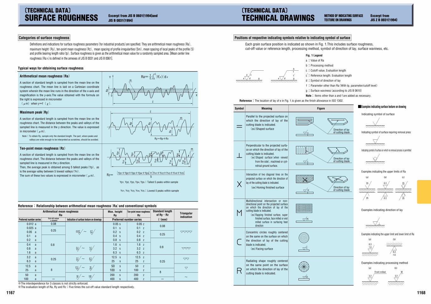
SURFACE ROUGHNESS BY DIFFERENT PROCESSING METHODS INDICATIONS OF GEOMETRICAL TOLERANCE ON DRAWINGS Excerpt from JIS B 0021(1984)
Standard values of standard length(mm)
Forging
Casting
Die casting
Hot rolling
Cold rolling
Drawing
Extruding
Tumbling
Sandblasting
Rolling
Face cutter grinding
Planing
Cutter grinding
Precision boring
Filing
Round grinding
Boring
Drilling
Reaming
Broach grinding
Shaving
Grinding
Hone finishing
Super finishing
Buffing
Paper finishing
Lapping
Liquid honing
Burnishing
Surface rolling
Electric discharge carving
Wire cut electric spark
Chemical polishing
Electrolytic abrasion
Carving( Slotting)
Precision
Precision
Precision
Precision
Precision
Precision
Precision
Precision
Precision
Precision
Precision
Precision
Precision
Precision Fine Medium Rough
Precision Fine Medium Rough
Precision
Triangular indication
Max. heightRmax.
Arithmetical mean roughnessRa
Form
er de
signa
tions
of su
rface
roug
hnes
s
Examples of diagrammatical indication and its interpretationKind of tolerance
Straightness tolerance
Symbol
Flatness tolerance
Circularity tolerance
Cylindricity tolerance
Profile tolerance of line
Definition of tolerance zone
Profile toleranceof surface
Parallelismtolerance
Perpendicularitytolerance
Angularitytolerance
Measuring plane
Positionaltolerance
Coaxiality toleranceor
concentricity tolerance
Symmetrytolerance
Circularrun-out
tolerance
Total run-outtolerance
Thin alternate long and short dash line:Center lineThin alternate long and two short dashes line:Supplementary projection plane or sectional plane.Thick alternate long and two short dashes line:Projection of a feature to supplementary Projection plane or sectional plane
IKinds and symbols of geometrical tolerances
Lines used in the drawings in the column of ""definition of tolerance zone"" indicate the following meanings:
Thick solid line or broken line:FeatureThick alternate long and short dash line:DatumThin solid line or broken line:Tolerance zone
Where symbol F is attached before the numerical value indicating a tolerance zone, this tolerance zone is a zone in a cylinder of diameter t.
The tolerance zone is a zone held between two parallel planes a distance t apart.
The tolerance zone in the considered plane is a zone between two concentric circles a distance t apart.
The tolerance zone is a zone contained between two coaxial cylinder surfaces a distance t apart.
The tolerance zone is a zone held between two lines enveloping circles of diameter t, the centers of which are situated on a theoretically exact profile line.The tolerance zone is a zone held between the two surfaces enveloping the spheres of diameter t, the centers of which are situated on a theoretically exact profile surface.The tolerance zone is a zone held between two parallel planes parallel to the datum plane and a distance t apart from each other.
Where symbol F is attached before the numerical value indicating the tolerance, the tolerance zone is a zone within a cylinder of diameter t perpendicular to the datum plane.The tolerance zone is a zone held between two parallel planes inclined at the specified angle to the datum plane and a distance t apart from each other.
The tolerance zone is a zone within a circle or sphere of diameter t having its center at the theoretically exact location, hereinafter referred to as the ""true location"".Where symbol F is attached before the numerical value indicating the tolerance, the tolerance zone is a zone within a cylinder of diameter t whose axis agrees with the datum axial straight line.The tolerance zone is a zone held between two parallel planes a distance t apart from each other and arranged symmetrically about the datum median plane.
The tolerance zone is a zone between two coaxial cylinders having axes agreeing with the datum axial straight line and a distance t apart from each other in the radial direction.
The total radial run-out of the cylinder surface shown by the arrow of the leader line shall not exceed 0.1mm at any point on the cylinder surface when the cylinder part is rotated about the datum axial straight line A-B with a relative movement in the axial direction.
The tolerance is a zone between two concentric circles whose centers agree with the datum axial straight line on any measuring plane normal to the datum axial straight line and which are a distance t apart from each other in the radial direction.
The median surface shown by the arrow of the leader line shall be contained between two parallel planes 0.08mm apart form each other and arranged symmetrically about the datum median plane A.
The run-out in the radial direction of the cylinder surface shown by the arrow of the leader line shall not exceed 0.1mm on any measuring plane normal to the datum axial straight line when the cylinder is rotated by one rotation about the datum axial straight line A-B.
The axis shown by the arrow of the leader line shall be contained within a cylinder of 0.01mm diameter whose axis agrees with the datum axial straight line A.
The point shown by the arrow of the leader line shall be contained within a circle of 0.03mm diameter having its center at the true location 60mm and 100mm apart, respectively, from the datum straight line A and from the datum straight line B.
The surface shown by the arrow of the leader line shall be contained between two parallel planes which are inclined at 40B with theoretical exactness to the datum plane A and which are 0.08mm apart from each other in the direction of the arrow of the leader line.
In any cross-section parallel to the projection plane the considered profile shall be contained between two lines enveloping circles of 0.04mm in diameter, the centers of which are situated on a surface having the theoretically exact profile.
The considered surface shall be contained between two surfaces enveloping the spheres of diameter 0.02mm, the centers of which are situated on a surface having the theoretically exact profile.The surface shown by the arrow of the leader line shall be contained between two planes parallel to the datum plane A and 0.01mm apart from each other in the direction of the arrow of the leader line.
The axis of the cylinder shown by the arrow of the leader line shall be contained within a cylinder of diameter 0.01mm perpendicular to the datum plane A.
The considered surface shall be contained between two coaxial cylinder surfaces 0.1mm apart.
The circumference in any section normal to the axis shall be contained between two concentric circles 0.1mm apart on the same plane.
This surface shall be contained between two parallel planes 0.08mm apart.
Where a tolerance frame is connected to the dimension showing the diameter of a cylinder, the axis of the cylinder shall be contained a cylinder of 0.08mm diameter.
Wor
king
met
hod
Form
tole
ranc
eOr
ient
atio
n to
lera
nce
Loca
tion
tole
ranc
eRu
n-ou
t tol
eran
ce
TECHNICAL DATA TECHNICAL DATA
Precision
Precision
Truelocation
Tolerance surface
PD-5 2nd
sr
rad
cd
mol
K
A
s
kg
m
2
3
3
2
3
-1
2
3
2
cd/mm /kgmol/mA/mA/mkg/m
mm/sm/smm
2
-6
22
2
M10
3
6
-1
-2
4
2
6
-4
-6
cal/(gCA)kcal/(kgCA)
18.600 0M10
1.162 791
1
1M10
1M10
1M10
1
1M10
1M10
1M10
1
St
kcal/(hCm CA)
kcal/(hCmCA)
cSt
J/(kgCK)
2W/(m CK)
W/(mCK)
2m /s
1
3.600
9.806 65
4.186 05M10
2
-5
-2
-1
-7
-24
6
6
1
1M10
1.019 72M10
1.019 72M10
1M10
1
1.019 72M10
1.019 72M10
9.806 65M10
9.806 65
1
1M10
9.806 65M10
9.806 65M10
1M10
1
kcal/hPSkgfCm/s
kcalkgfCmkWCh
kgf/cmkgf/mm
W
J
2
5
4
5
6
3
1.333 22M10
9.806 65
1.013 25M10
9.806 65M10
1M10
1M10
1M10
1
atmkgf/cmMPakPa barPa
PcPkgfdyn
-1
-3
1
1M10
1M10 2
31M10
1
1M10
-2
1M10
1M10
1
-6
-1
1
1.019 72M10
1.019 72M105
59.806 65M10
1
1M10-5
9.806 65
1M10
1
PaCsN
kMGTPE
310
610
910
1210
1510
1810 10 2
1010-1
10-2
10-3
10-6
hdadcmO
10-9
10-12
10-15
10-18
npfa
1
1M10
1M10
9.806 65M10
1.013 25M10
9.806 65M10
1.333 22M10
3
2
2
-1
-31M10
-3 -6
1M10-6
-4
-1
-1
1.333 22M10
9.806 65M10
1.013 25M10
9.806 65M10
1M10
1
-31M10
-2 -1
1M10-2
1M10
1
9.806 65M10
1.013 25
9.806 65M10
1.333 22M10-3
-51M10
-5 -4
1.019 72M10-5
-31.359 51M10
1M10
1.033 23
1
1.019 72
1.019 72M10
-21.019 72M10 9.869 23M10-3
9.869 23
9.869 23M10
9.678 41M10
1
9.678 41M10
1.315 79M10-3
-69.869 23M10
-5
-1
-1 4
4
1.019 72M10 -1
1.359 51M10
1
1.033 23M10
1M10
1.019 72M10
1.019 72M10
21.019 72M105
4 2
3
7.500 62
7.500 62M10
7.500 62M10
7.355 59M10
7.600 00M10
7.355 59M10
1
-37.500 62M10
2
2
-2
1.162 79M10
2.724 07M10
1
-3
2.777 78M10-7
-6
-11.019 72M10
24.268 58M10
1
3.670 98M10 5 28.600 0
1
2.388 89M10-4
2.342 70M10-3
M10
1.162 79
9.806 61
1
7.355 2M10 M107.5
1
1.185 72M10
1.019 72M10-1
-1
-21.333 33M10
1
1.580 95M10 -3
1.359 62M10 -3
26.325 29M10
-18.600 0
1
8.433 71
M10
11.162 79
8.600 0M101
14.186 05M10
2.388 89M10 -4
1-3
-1
mmH20
11641163
SvGyBqlxlmA
HT
WbS
FVCWJ
PaNHz
-1
2
2
-1
2
2
-1
1 Sv=1J/kg1 Gy=1J/kg1 Bq=1s1 lx=1lm/m1 lm=1cdCsr1 t=(t+273.15)K1 H=1Wb/A1 T=1Wb/m1 Wb=1VCs1 S=1 1 =1V/A1 F=1C/V1 V=1J/C1 C=1ACs1 W=1J/s1 J=1NCm1 Pa=1N/m1 N=1kgCm/s1 Hz=1s
Pa N/m2 MPa N/mm2
Table 2. Supplementary unit
Table 1. Base unit
DefinitionSign
Steradian
Radian
Unit
Solid angle
Plane angle
Volume
)aThe elementary unit must be specified and must be an atom, molecule, ion, electron, photon or a specified group of such units.1
DefinitionUnitVolume
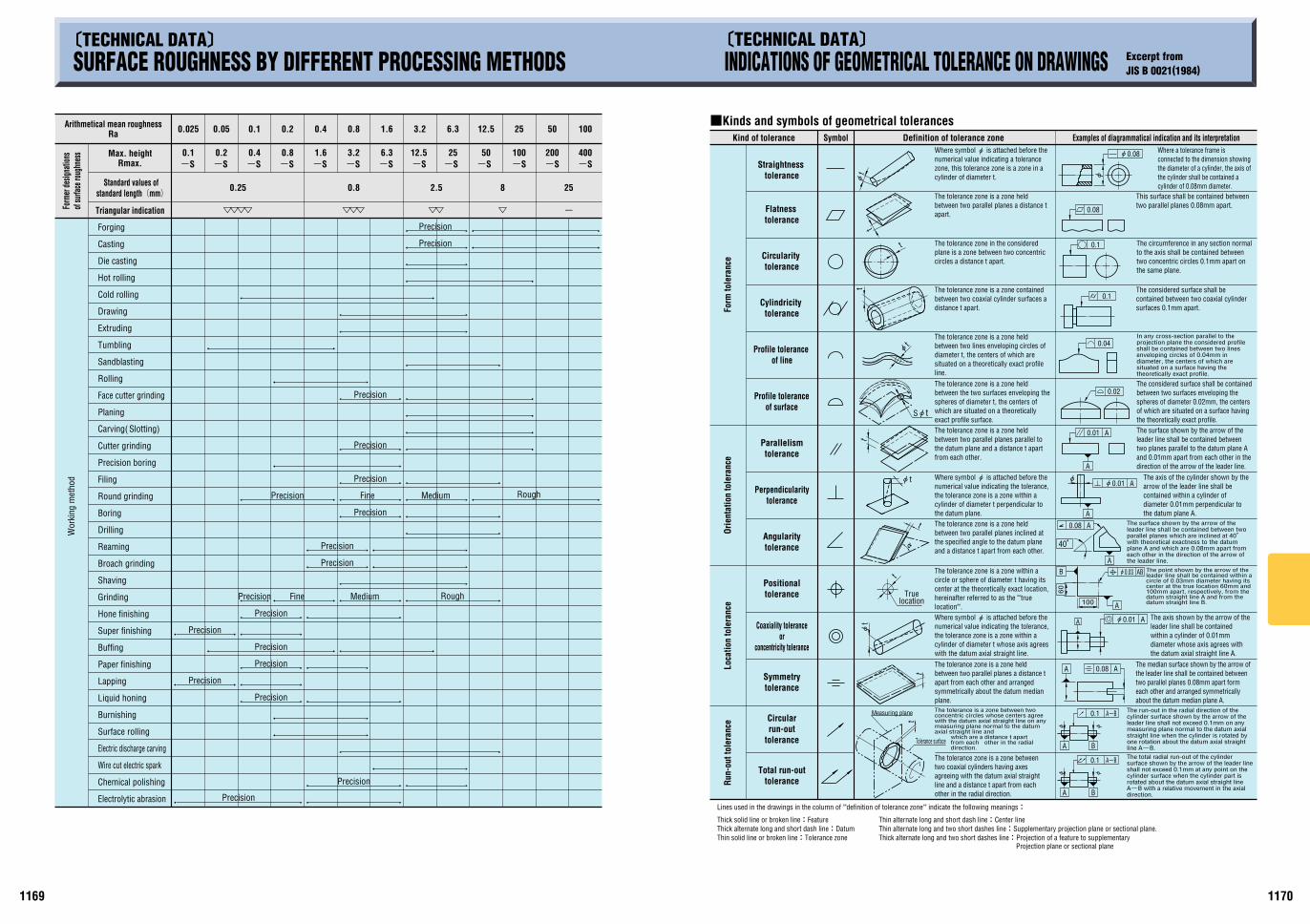
The steradian is the unit of measurement for solid angles, equal to the solid angle subtended center of a sphere by a portion of the surface of the sphere whose area equals the square of the sphere's radius.
The radian is a unit of plane angle, defined as the central angle of a circle determined by two radii and an arc joining them, all of the same length.
The candela is a unit of luminous intensity, defined as the luminous intensity of a steradian light source which emits a a monochrome radiation at a frequency of 540M1012, in a specified direction and at a force equal to watts.
The mole is the amount of substance of a system(with a specific composition)which contains as many elementary units( 1 )as there are atoms of carbon in 0.012 kilogram of pure nuclide carbon 12.The mole is used to specify both the elementary unit and system.
The kelvin is a unit of absolute temperature equal to of the absolute temperature of the triple point of water.
The ampere is a unit of electric current, defined as a 2M10-7 newton force of attraction exerted at 1 meter intervals between two parallel current-carrying linear conductors that are infinitely small in circular cross-sectional area and infinitely long in length.
The second is a fundamental unit of time, equal to 9,192,631,770 periods of radiation corresponding to the transition between two superfine levels of the ground state of an atom of cesium-133.
international prototype stored in Sevres, France.The kilogram is a unit of mass(not weight nor force), equal to the mass of an
Sign
Candela
Mole
Kelvin
Ampere
Second
Kilogram
Meter
Note(
Luminous intensity
Amount ofsubstance
Thermodynamic temperature
Electric current
Time
Mass
Length
Those units given in Table 1.Those units given in Table 2.
Generic term used to describe base units, supplementary units or derived units of the International System of Units(SI).
It contains base units and supplementary units, units derived from them, and their integral exponents to the 10th power.Coherent system of units adopted and recommended by the International committee on Weights and Measures.(1)International System
of Units(SI)
Celsius degreeor Degree
SievertGray
BecquerelLux
Lumen
HenryTesla
WeberSiemens
OhmFaradBolt
CoulombWattJoulePascalNewton
Herz
Volume
Radio equivalentQuantity of absorption radioRadioactivityIlluminationLight fluxCelsius temperatureInductance
Magnetic flux density,magnetic induction
Magnetic fluxConductanceElectric resistanceElectrostatic capacity, capacitance
Potential, potential difference, voltage, electromotive force
Electric charge, quantity of electricity
Work rate, process rate,power, electric power
Energy, work, heatPressure, stressForceFrequency
SymbolName
Derived units
2
Candela every square meterCubic meter every kilogramMole every cubic meterAmpere every meterAmpere every square meterKilogram every cubic meterEvery meterMeter/secondMeter/secondCubicSquare
SymbolName
Derived units
LuminanceSpecific volume
Concentration of substanceMagnetic field strengthElectric current density
DensityWave numbers
AccelerationVelocityVolume
Area
Volume
Example of the units derived from the base units Table 3. The derived units having proper names
(5)Derived unitsunits and supplementary units. Besides, the derived units that have proper names are shown in Table 3.The units of derived quantity in International units. Those are expressed algebraically in terms of the base
Terminology used in this specification and definitions thereof are as follows
This standard specifies how to use the International System of Units(SI)and other international unitary systems, as well as units used in correlation with units from international systems, and other units which made be used.
(2)SI unit(3)Base unit(4)Supplementary unit
1-2. Terminology and definitions
1-1. Sphere of application1. International units SI and the method of use
mmHg or Torr
Note)
1 W=1 J/s,PS:French horsepowerNote)
Note)
Note)
Note)
Note)
Stre
ssFo
rce
Pres
sure
Work
, en
erg
y,qu
antity
of
hea
tPo
wer,
heat
flow
rate
(The units contained in bold lines are SI units.)2. Table of conversion rate of JIS units attendant upon switchover to SI units
KiloMegaGigaTeraPetaExsa
Multiple to be combined with unit SymbolName
Prefixes
Table 4. Prefixes
The multiple for composing the integral multiplication of 10 in SI units, names of prefixed and their symbols are shown in Table 4.(1)Prefixes1-3. Integral multiplication in SI units
Multiple to be combined with unit
Prefixes
Name SymbolMultiple to be
combined with unitPrefixes
Name SymbolHectDecaDeciCentiMilli
Micro
NanoPicoFemtAto
The meter is the distance light travels in of a second in a vacuum.1299, 792, 458
6831
1273.16
Excerpt from JIS Z 8203(1985)
TECHNICAL DATA SI(Système International d'Unités)
SI is the abbreviation of Systeme International d'Unites(International System of Units).
Expressing method by derived unit or supplementary unit/others
Visc
osity
Kinem
atic v
iscos
ityT
her
mal
con
du
ctiv
ity
Spec
ific
heat
Coeff
icien
t of
heat
trans
fer
2 21 Pa=1 N/m , 1Mpa N/mm
=1 NCS/m ,1 cP=1mPaCs21 PaCs
2=1 dynCs/cm =1 g/cmCs1 P
221 St=1cm /s, 1 cSt=1mm /S
1 J=1 WCs,1 J=1NCm
21 Pa=1 N/m
or or
PD-2 1st

1020
3040
5060
70
ED
M
WE
DM
Wn
CU-
Zn
-
Wn
CU-
DWA
A PA GC C CBN
DCBN
Wn-
Co
SKH-
Wn-
Co
SKH-
SKH-
Wn-
Co
S45C
( AI-
allo
i)SS
400(
SS41
) S
KD11
S50C
DC
53
SKD6
1
STAV
AX E
SR
STAV
AX ES
RST
AVAX
ESR
ORAV
AR S
UPRE
ME
RIGO
RRI
GOR
( AI)
CU BsBM
2
HRC
( Be-
Cu)
SCM
435
HPM
2T
HPM
7
NA
K55
PX5
HPM
1NA
K80
HPM
38
H
PM50
DH2F
SUJ2
S45C
SKS3
SKH5
1
DC53
SKD1
1
HPM
38S-
STAR
FDAC
SKD6
1S-
STAR
JIS
AISI
DIN
ISO
YC3
YCS3
SGT
CRD
SLD
SLD8
SLD1
0AR
K1SC
DHP
M2T
PRE2
HMD5
HMD1
ACD3
7
YSM
ACD8
YXM
1
YXM
4
XVC5
YXR3
3YX
R3YX
R7
HAP4
0
HAP5
R
HAP1
0
HAP5
0
HAP7
2
SK3
SK30
1SK
S3
SKD1
SKD1
1
AUD1
5
SXAC
ESK
D12
SX10
5VSX
4AK
S3
AKS4
AUD1
1SX
5SX
44
QK3
QKSM
QKS3
QC1
QC11
QCM
8QC
M10
QCM
7
QF3
QF1
QH51
QHZ
SPM
23
SPM
60
YK3
YK30
GOA
DC1
DC11
DC53
DCX
DC12
GO40
FCX
1
GO5
GO4
GS5
MH5
1
MH5
5
MH8
MH8
5M
H88
DEX4
0DE
X-M
1DE
X-M
3
DEX2
1DE
X60
DEX6
1DE
X80
K3 K3M
KS3
KD1
KD11
KD11
SKD
21
KD12
KAP6
5RC
55
FH5
KSM
KTV5
H51
HM35
MV1
0
KXM
KMX2
KMX3
SK3M
SKS3
CDS1
1
MDS
9
SRS6
ICS2
2M
CR1
SKH9
HM35
HS53
MHS
93R
HS98
MFM
38V
MDS
1M
DS3
MDS
7M
ATRI
X2AT
M3
FAX3
8
FAX3
1
FAX5
5FA
XG1
FAX1
8FA
XG2
RS3
RD11
RHM
1
RHM
5
RHM
7
ARNE
SVER
KER3
SVER
KER2
1
SLEI
PNER
RIGO
RIM
PAX
FERN
O
PREG
ACO
MPA
XCA
LMAX
VIKI
NGEL
MAX
VANA
DIS4
VANA
DIS6
VANA
DIS1
0
ASP3
0
ASP2
3
ASP6
0
K990
K460
K100
K107
K105
K110
K340
K305
K630
K190
S600
S705
S700
S590
S690
S790
S390
KHA3
0
KHA3
VN
KHA3
2
KHA6
0KH
A77
KHA3
0NKH
A33N
KHA3
NHKH
A5NH
W1-
10
D3 D2 A2 M2
TC10
5
X210
Cr12
X210
Cr12
W12
X100
CrM
oV5
HS6-
5-2
HS6-
5-2-
5
HS10-
4-3-
10
HS6-
5-3-
8
11921191
COMPARISON OF DIE STEEL BY MANUFACTURERSHi
tach
iM
etal
s, L
td.
Aich
i Ste
elW
orks
., Lt
d.Ko
be S
teel
Co.,
Ltd
.Sa
nyo S
pecia
lSte
el Co
., Ltd
.Da
ido
Stee
lCo
., Lt
d.Na
chi-Fu
jikosh
iCo
rp.Ri
ken
Seik
oCo
., Lt
d.Bo
hler
(Ge
rman
y)Ud
deho
lm(
Swed
en)
Nippon
Koshu
haSte
el Co.,
Ltd.
Cate
gory
ICO
MPA
RISO
N OF
DIE
STE
EL B
Y M
ANUF
ACTU
RERS
Carbo
n too
l stee
l
Pow
dere
dhi
gh-s
peed
tool
ste
el
High
-spe
edto
ol s
teel
Allo
y too
l ste
el
Inte
rnat
iona
l Sta
ndar
ds re
late
d sy
mbo
ls
Refe
renc
e m
ater
ial:
"Spe
cial
ste
el" N
ovem
ber 2
001
SKS9
3SK
S3
SKD1
SKD1
1
CrSKD
in ma
trix gro
upSK
D12
Preh
arden
40HR
CPre
harden
50HRC
or mo
re
Flame
-harde
ned ste
el
Low tem
peratur
e air-co
oled ste
el
High-i
mpac
t stee
l
Othe
rs
SKH5
1
SKH5
5 gr
oup
SKH5
7 gr
oup
Mat
rix g
roup
SKH4
0
Mat
rix g
roup
Othe
rs
SK
10
5(P
revio
us
sele
ct
SK
3)
SKD1
1(
Mod
ifica
tion)
Mat
rix g
roup:
The
tool
ste
el ty
pe th
at a
ccel
erat
es to
ol w
ear a
t cut
ting
and
enha
nces
its
toug
hnes
s
Mac
hine
d m
ater
ials
Nonferr
ous me
talUn
treat
edHa
rden
ed m
ater
ials
Quen
ched
/Tem
pere
d ( SKD
12gr
oup)
( Car
bide
)
( Elec
trofor
ming
/outsi
de)
( Elec
trofor
ming
/insid
e)
Tool
mat
eria
ls
Tool
s m
ater
ials
Mat
eria
ls
Parts
mat
eria
lsFo
r pr
ess
die
For
plas
ticm
old
Taps
Mag
nets
grind
stone
Drill
s
Ream
ers
End
mill
s
Cuttin
g too
ls
Electro
de ma
ster
Wire
Carb
ide
High
-spe
ed s
teel
High
-spe
ed s
teel
Carb
ide
High
-spe
ed s
teel
Carb
ide
Boro
n
Diam
ond
Electr
odep
osite
d bor
on
Blac
k sil
icon
carb
ide
Gree
n silic
on ca
rbide
Pink f
used
alum
ina
Brow
n fus
ed al
umina
Whit
e fus
ed al
umina
Electr
odep
osite
d diam
ond
Electr
olytic
copp
er, Br
ass
Copper
tungst
en, Sil
ver tun
gsten
Bras
s
Tung
sten
( Non
ferr
ous
met
al)
( Non
ferr
ous
met
al)
( Non
ferr
ous
met
al)
( Car
bide
)
( Car
bide
)
Jig
grin
der
Surfa
ce g
rinde
r
Form
ing
grin
der
Cylin
dric
al g
rinde
r
Prof
ile g
rinde
r
Taps
Mag
nets
grind
stone
Elec
trode
mas
ter
Wire
Drill
s
Cuttin
g too
ls
Taps
Ream
ers
Drill
s
Cuttin
g too
ls
Ream
ers
NC m
illin
g cu
tter
Gene
ral pu
rpos
e milli
ng cu
tter
Mac
hini
ng c
ente
rDr
illin
g m
achi
ne
Jig
bore
r
Drill
pre
ssBo
ring
mac
hine
NC la
the
Gene
ral p
urpo
se la
the
Turn
ing
cent
er
Drill
s
Cuttin
g too
ls
Ream
ers
End
mill
s
Cutti
ng
Boring
on
flanks
and bo
ttom
Grin
ding
Elec
troer
osio
n
Borin
g
Machi
ning
cylind
er
Equi
pmen
tPr
oces
sing
m
etho
dRe
quire
d to
ols
HARDNESS OF MATERIAL AND CORRESPONDING TOOLS
( SKD
12gr
oup)
Ade-
har
den
ed(
) MAS
1C
X210C
r12
H6.5
.2
S6.2
.5
S10-
4-3-
10
1.20
80
1.23
63
1.33
43
1.32
43
1.32
07
1.23
79
PD-16 2nd
’TECHNICAL DATA» ’TECHNICAL DATA»
SUS
201
SUS
202
SUS
301
SUS
301L
SUS
301J
1SU
S 30
2SU
S 30
2BSU
S 30
3SU
S 30
3Se
SUS
303C
uSU
S 30
4SU
S 30
4L
SUS
304N
1SU
S 30
4N2
SUS
304L
NSU
S 30
4J1
SUS
304J
2SU
S 30
4J3
SUS
305
SUS
305J
1SU
S 30
9SSU
S 31
0SSU
S 31
5J1
SUS
315J
2SU
S 31
6SU
S 31
6FSU
S 31
6L
SUS
316N
SUS
316L
N
SUS
316T
iSU
S 31
6J1
SUS
316J
1LSU
S 31
7SU
S 31
7LSU
S 31
7LN
SUS
317J
1SU
S 31
7J2
SUS
317J
3LSU
S 83
6LSU
S 89
0LSU
S 32
1SU
S 34
7SU
S 38
4SU
S XM
7SU
S XM
15J1
SUS
329J
1SU
S 32
9J3L
SUS
329J
4L
12 5 4 13 6 1 2 10 3 8
X6Cr
Ni23-1
4X6
CrNi2
5-21
26 27 19 20 22 23 28 21 24 31 15 17 9D2
6(1 )
33 34
S201
00S2
0200
S301
00
S302
00S3
0215
S303
00S3
0323
S304
00S3
0403
S304
51S3
0452
S304
53
S304
31S3
0500
S309
08S3
1008
S316
00
S316
03
S316
51S3
1653
S316
35
S317
00S3
1703
S317
53
N083
67N0
8904
S321
00S3
4700
S384
00S3
0430
S381
00S3
2900
S392
40S3
9275
201
202
301
302
302B
303
303S
e
304
304L
304N
304L
N
S304
3130
5
309S
310S
316
316L
316N
316L
N
317
317L
N089
0432
134
738
430
4Cu
329
S318
03S3
1260
284S
1630
1S21
302S
25
303S
2130
3S41
304S
3130
4S11
305S
19
310S
31
316S
31
316S
11
317S
1631
7S12
904S
1432
1S31
347S
31
394S
17
X12C
rNi17
7X2
CrNi
N18-
7X1
2CrN
i17 7
X10C
rNiS1
8 9
X5Cr
Ni18
10
X2Cr
Ni19
11
X2Cr
NiN1
8 10
X5Cr
Ni18
12
X5CrN
iMo1
7 12 2
X5CrN
iMo1
7 13 3
X2CrN
iMo1
7 13 2
X2CrN
iMo1
7 14 3
X2CrNi
MoN1
7 12 2
X2CrNi
MoN1
7 13 3
X6CrNi
MoTi1
7 12 2
X2CrN
iMo1
8 16 4
X6Cr
NiTi1
8 10
X6Cr
NiNb1
8 10
Z12C
MN17
-07Az
Z11C
N17-
08
Z12C
N18-
09
Z8CN
F18-
09
Z7CN
18-0
9Z3
CN19
-11
Z6CN
19-0
9Az
Z3CN
18-1
0Az
Z8CN
18-1
2
Z10C
N24-
13Z8
CN25
-20
Z7CN
D17-1
2-02
Z6CN
D18-1
2-03
Z3CN
D17-1
2-02
Z3CN
D17-1
3-03
Z3CN
D17-1
1Az
Z3CN
D17-1
2Az
Z6CN
DT17
-12
Z3CN
D19-1
5-04
Z3CN
D19-1
4Az
Z2NC
DU25
-20
Z6CN
T18-
10Z6
CNNb
18-1
0Z6
CN18
-16
Z2CN
U18-
10Z1
5CNS
20-1
2
Z3CN
DU22
-05Az
Z3CN
DU25
-07Az
12X1
7 9A
H407
X16H
6
12X1
8H9
12X1
8H10
E
08X1
8H10
03X1
8H11
06X1
8H11
10X2
3H18
03X1
7H14
M3
08X1
7H13
M2T
08X1
8H10
T08
X18H
12
08X2
1H6M
2T
X12C
rMnN
iN17-7
-5X1
2CrM
nNiN1
8-9-5
X5Cr
Ni17
-7X2
CrNi
N18-
7
X8Cr
NiS1
8-9
X4Cr
Ni18
-10
X2Cr
Ni19
-11
X2Cr
Ni18
-9
X2Cr
NiN1
8-10
X4Cr
Ni18
-12
X6Cr
Ni25
-20
X4Cr
NiMo
17-1
2-2
X4Cr
NiMo
17-1
3-3
X2Cr
NiMo
17-1
2-2
X2Cr
NiMo
17-1
3-3
X2Cr
NiMo
18-1
4-3
X2CrN
iMoN
17-11
-2X2
CrNiM
oN17
-13-3
X6CrN
iMoT
i17-12
-2
X2CrN
iMo1
8-15-4
X2CrN
iMoN
18-12
-4X2
CrNiM
oN17
-13-5
X1CrN
iMoCu
N25-2
5-5X6
CrNi
Ti18
10X6
CrNi
Nb18
10
X3Cr
NiCu
18-9
-4X1
CrNi
Si18
-15-
4
X2Cr
NiMoN
22-5-
3X2
CrNiM
oCuN
25-6-
3
1.43
721.
4373
1.43
191.
4318
1.43
05
1.43
011.
4307
1.43
071.
4306
1.43
11
1.43
03
1.44
011.
4436
1.44
041.
4432
1.44
35
1.44
061.
4429
1.45
71
1.44
381.
4434
1.44
39
1.45
391.
4541
1.45
50
1.45
871.
4381
1.44
621.
4507
UN
SA
ISI
BS
DIN
NF
O
CT
JIS
SUS
405
SUS
410L
SUS
429
SUS
430
SUS
430F
SUS
430L
X
SUS
430J
1LSU
S 43
4SU
S 43
6LSU
S 43
6J1L
SUS
444
SUS
445J
1SU
S 44
5J2
SUS
447J
1SU
S XM
27SU
S 40
3SU
S 41
0SU
S 41
0SSU
S 41
0F2
SUS
410J
1SU
S 41
6SU
S 42
0J1
SUS
420J
2SU
S 42
0FSU
S 42
0F2
SUS
429J
1SU
S 43
1SU
S 44
0ASU
S 44
0BSU
S 44
0CSU
S 44
0FSU
S 63
0SU
S 63
1SU
S 63
2J1
SUH
31SU
H 35
SUH
36SU
H 37
SUH
38SU
H 30
9SU
H 31
0SU
H 33
0SU
H 66
0SU
H 66
1SU
H 21
SUH
409
SUH
409L
SUH
446
SUH
1SU
H 3
SUH
4SU
H 11
SUH
600
SUH
616
40 41 42 44 43 46 48 39 49 50 51 57 58 59
X53CrM
nNi21
4
(2)
37 36X1
5CrN
26(2 )
X45C
rSi9-
3(2)
X50C
rSi18-
2(2 )
S405
00
S429
00S4
3000
S430
20S4
3035
S434
00S4
3600
S444
00
S447
00S4
4627
S403
00S4
1000
S410
08
S410
25S4
1600
S420
00S4
2000
S420
20
S431
00S4
4002
S440
03S4
4004
S440
20S1
7400
S177
00
S630
08S6
3017
S309
00S3
1000
N083
30S6
6286
R301
55
S409
00
S446
00S6
5007
S422
00
405
429
430
430F
434
436
444
403
410
410S
416
420
420
420F
431
440A
440B
440C
S440
20S1
7400
S177
00
309
310
N083
30
409
446
405S
17
430S
17
434S
17
410S
2140
3S17
416S
2142
0S29
420S
37
431S
29
331S
4234
9S52
349S
5438
1S34
309S
2431
0S24
409S
19
401S
45
443S
65
X6Cr
Al13
X6Cr
17X7
CrM
oS18
X6Cr
Ti17
X6Cr
Nb17
X6Cr
Mo1
7 1
X10C
r13
X6Cr
13
X20C
r13
X30C
r13
X20C
rNi17
2
X7Cr
NiAl
17 7
X53C
rMnN
i21 9
CrNi
2520
CrAI
1205
X6Cr
Ti12
X45C
rSi9
3
Z8CA
12Z3
C14
Z8C1
7Z8
CF17
Z4CT
17
Z4CN
b17
Z8CD
17-0
1
Z3CD
T18-
02
Z1CD
26-0
1
Z13C
13Z8
C12
Z11C
F13
Z20C
13Z3
3C13
Z30C
F13
Z15C
N16-
02Z7
0C15
Z100
CD17
Z6CN
U17-
04Z9
CNA1
7-07
Z35C
NWS1
4-14
Z52C
MN21
-09Az
Z55C
MN21
-09Az
Z15C
N24-
13Z1
5CN2
5-20
Z12N
CS35
-16
Z6NC
TV25
-20
Z6CT
12Z3
CT12
Z12C
25Z4
5CS9
Z40C
SD10
Z80C
SN20
-02
12X1
7
08X1
3
20X1
330
X13
20X1
7H2
95X1
8
09X1
7H7
IO
45X1
4H14
B2M
55X2
0 9A
H4
20X2
5H20
C2
15X2
8
40X1
0C2M
40X
9C2
20X1
2BHM
F
X6Cr
Al13
X6Cr
17X6
CrM
oS17
X3Cr
Ti17
X2Cr
Ti17
X3Cr
Nb17
X6Cr
Mo1
7-1
X1Cr
MoT
i16-
1
X2Cr
MoT
i18-
2
X12C
r13
X6Cr
13
X12C
rS13
X20C
r13
X30C
r13
X29C
rS13
X19C
rNi1
7 2
X70C
rMo1
5
X105
CrM
o17
X5Cr
NiCu
Nb16
-4X7
CrNi
Al17
-7
X2Cr
Ti12
1.40
02
1.40
161.
4105
1.45
101.
4520
1.45
111.
4113
1.45
13
1.45
21
1.40
061.
4000
1.40
051.
4021
1.40
281.
4029
1.40
571.
4109
1.41
25
1.45
421.
4568
1.45
12
UN
SA
ISI
BS
DIN
NF
O
CT
JIS
SKH
2SK
H 3
SKH
4SK
H10
SKH5
1SK
H52
SKH5
3SK
H54
SKH5
5SK
H56
SKH5
7SK
H58
SKH5
9SK
S11
SKS
2SK
S21
SKS
5SK
S51
SKS
7SK
S 8
SKS
4SK
S41
SKS4
3SK
S44
SKS
3SK
S31
SKS9
3SK
S94
SKS9
5SK
D 1
SKD1
1SK
D12
SKD
4SK
D 5
SKD
6SK
D61
SKD6
2
TC14
0TC
120
TC10
5TC
90
TC 9
0TC
80
TC 8
0TC
70
-
HS18-
0-1
HS18-
1-1-
5HS
18-
0-1-
10HS
12-
1-5-
5HS
6-
5-2
-
HS 6-
5-3
-
HS 6-
5-2-
5-
HS10-
4-3-
10HS
2-
9-2
HS 2-
9-1-
8-
105W
Cr1
- - - - - - -
TCV1
05- -
105W
Cr1
- - -
210C
r12
-
100C
rMoV
530
WCr
V530
WCr
V9-
40Cr
MoV
5-
-
W1-
111 /
2
W1-
10
W
1- 9
W1-
8
- - T 1
T 4
T 5
T15
M2
M
3-1
M3-
2M
4
- M36 - M7
M42 F2 - - - L6 - - - -
W2-
91 /2
W2-
8
- - - - - D3 D2 A2 - H21
H11
H13
H12
- - - - - - - BT 1
BT 4
BT 5
BT15
BM 2- -
BM 4
BM35- BT
42-
BM42- - - - - - - - - BW
2- - - - - - BD
3BD
2BA
2- BH
21BH
11BH
13BH
12
- -
C105
W1
-
C 8
0W1
C 8
0W1
C
70W
2-
S18-
1-2-
5-
S12-
1-4-
5S
6-
5-2
-
S 6-
5-3
-
S 6-
5-2-
5-
S10-
4-3-
10-
S 2-
10-
1-8
-
105W
Cr6
- - - - - - - - - -
105W
Cr6
- - -
X210
Cr12
- - - -
X38C
rMoV
51X4
0CrM
oV51
-
C140
E3U
C120
E3U
C105
E2U
C 9
0E2U
C 9
0E2U
C 8
0E2U
C 8
0E2U
C 7
0E2U
C 7
0E2U
HS18-
0-1
HS18-
1-1-
5HS
18-
0-2-
9HS
12-
1-5-
5HS
6-
5-2
-
HS 6-
5-3
HS 6-
5-4
HS 6-
5-2-
5HC
-
HS10-
4-3-
10HS
2-
9-2
HS 2-
9-1-
8-
105W
Cr5
- - - -
C140
E3UC
r4- -
100V
2- -
105W
Cr5
- - -
X200
Cr12
X160
CrM
oV12
X100
CrM
oV5
X32W
CrV3
X30W
CrV9
X38C
rMoV
5X4
0CrM
oV5
X35C
rWM
oV5
- - - - - - -
P6M
5K5
- - - -
XB4
XB
- - - - 13X- - - -
9XB
XB
- - - X12- - - -
4X5MF
C
4X5MF
1C3X
3M3F
Y13
Y12
Y11
Y10
Y8
Y9 Y8 Y7 P18
JIS G
440
4
JIS G
440
3
VD
Eh
DIN
AIS
IB
SIS
ON
F
OC
TA
ST
MJI
S G
440
1SK
D 7
SKD
8SK
T 3
SKT
4
30Cr
MoV
3- -
55Ni
CrM
oV2
H10
H19- -
BH10
BH19
-
BH22
4/5
X32C
rMoV
33- -
55Ni
CrM
oV6
32Cr
MoV1
2-18
-
55Cr
NiM
oV4
55Ni
CrM
oV7
- - -
5XHM
SUP
3
SUP
6SU
P 7
SUP
9SU
P 9
ASU
P10
SUP1
1ASU
P12
SUP1
3SU
M11
SUM
12SU
M21
SUM
22SU
M22
LSU
M23
SUM
23L
SUM
24L
SUM
25SU
M31
SUM
31L
SUM
32SU
M41
SUM
42SU
M43
SUJ
1SU
J 2
SUJ
3
SUJ
4SU
J 5
-
59Si
759
Si7
55Cr
3-
51Cr
V460
CrB3
55Si
Cr63
60Cr
Mo3
3- -
9 S2
011
SMn2
811
SMnP
b28
- -
11SM
nPb2
812
SMn3
5- - - - -
44SM
n28
- - -
1075
1078- 92
6051
5551
6061
5051
B60
9254
4161
1110
1108
1212
1213
12L1
312
15-
12L1
4- 11
17- - 11
3711
4111
4451
100
5210
0AS
TM A
485
Grad
e 1
- -
- - - - -
735A
51,73
5H51
-
685A
57,68
5H57
705A
60,70
5H60
- - -
(23
0M07)
- - - - - - -
210M
15,21
0A15
- -
(22
6M44)
- - - - -
- - -
55Cr
3-
50Cr
V4-
54Si
Cr6
- - - -
9 SM
n28
9
SMnP
b28
- -
9 SM
nPb2
89
SMn3
615
S10
- - - - - -
100C
r6
- - -
-
60Si
760
Si7
55Cr
3
60Cr
3
51Cr
V4-
54Si
Cr6
60Cr
Mo4
- - -
S250
S250
Pb- -
S250
PbS3
00
- -
(13
MF4
)
(35
MF6
)
(45
MF6
.1)
(45
MF6
.3)
-
100C
r6
- - -
60C2
60C2
- -
XFA5
0X F
A50
X P
- - - - - - - - - - - - - - - - - -
X1
5
- - -
VD
Eh
DIN
AIS
IB
SIS
ON
F
OC
TA
ST
MJI
S G
440
4
DIN
AIS
IB
SIS
ON
F
OC
TS
AE
JIS G
480
5
JIS G
480
4
JIS G
480
175
8085
80
11901189
ISO
TR
15
51
0LC
No.
ISO
TR
15
51
0LC
No
.
-
Spec
ial p
urpo
se s
teel
s
Allo
y to
olst
eel
JIS nu
mber・
name
Japa
n Ind
ustri
al Sta
ndard
sSt
eel t
ypes
rela
ted
to fo
reig
n st
anda
rds
Sym
bol
Sym
bol
JIS nu
mber・
name
Japa
n Ind
ustri
al Sta
ndard
sSt
eel t
ypes
rela
ted
to fo
reig
n st
anda
rds
High
-car
bon
chro
me
bear
ing
stee
l
Sulfu
r and
sulfu
rco
mbine
d free
cuttin
g stee
l
Sprin
g st
eel
(Co
ntin
ued)
SK
120(
Pre
vio
us
sele
ct
SK
2)
Tool
ste
els
and
rela
ted
mat
eria
ls
High
spe
edto
ol s
teel
JIS nu
mber・
name
Japa
n Ind
ustri
al Sta
ndard
sSt
eel t
ypes
rela
ted
to fo
reig
n st
anda
rds
Sym
bol
Carb
on to
olst
eel
SK
140(
Pre
vio
us
sele
ct
SK
1)
SK
105(
Pre
vio
us
sele
ct
SK
3)
SK
95(
Pre
vio
us
sele
ct
SK
4)
SK
85(
Pre
vio
us
sele
ct
SK
5)
SK
75(
Pre
vio
us
sele
ct
SK
6)
SK
65(
Pre
vio
us
sele
ct
SK
7)
JIS
G 43
03~
4305
Bar
Hot-ro
lled pla
te and
band
Cold-r
olled p
late and
band
JIS
G 43
08~
4309
Wire
rod
Wire
JIS
G 43
13~
4315
Ban
d fo
r spr
ing W
ire fo
r spr
ing W
ires for
cold f
orging
JIS
G 43
17~
4320
Hot-ro
lled equ
ilateral
angle ir
on C
old fin
ishing
bar
Billet f
or temp
ered ste
el prod
uct Col
d formi
ng equ
ilateral
angle ir
on
JIS
G 4
311~
4315
Heat r
esistin
g stee
l bar
Heat r
esisting
steel p
late
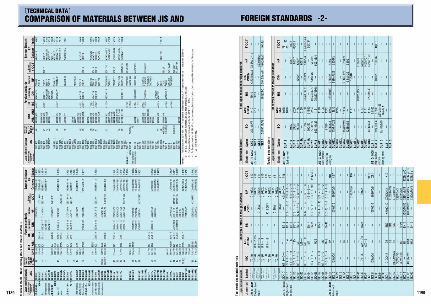
Rem
ark
1.Th
e ISO
is ba
sed on
the I
SO TR
1551
0:19
97. T
he co
de is
same a
s the
EN ex
pressi
on. H
oweve
r,(1 )
is base
d on t
he IS
O 495
4, an
d(2 )
is base
d on t
he IS
O 683C
15.
2.
For U
SA, U
NS re
gist
ratio
n nu
mbe
rs a
nd A
ISI s
teel
man
uals
are
refe
rred
.
3.
Euro
pean
sta
ndar
ds a
re b
ased
on
the
En10
088-
1: 1
995
4.
For E
urop
ean c
ount
ries,
BS, D
IN, N
F, etc
, has
been
refer
red,
but t
he sp
ecific
ation
s of e
ach c
ount
ry w
ill be
aboli
shed
by th
e EN
enac
tmen
t.
5.o
OCT
is b
ased
on
5632
.
Stai
nles
s st
eelsC
Heat
resi
stin
g st
eels
and
rela
ted
mat
eria
lsJa
pan I
ndus
trial
Stand
ards
Inte
rnat
iona
lSt
anda
rds
Fore
ign
stan
dard
sUS
AGe
rman
yFr
ance
UKRu
ssia
(Ol
d Sov
iet U
nion)
Cate
gory
Euro
pean
Sta
ndar
dsEN
Num
ber
JIS Nu
mberC
Name
(S
tain
less
ste
el
is
om
itte
d)
Japa
n Ind
ustri
al Sta
ndard
sFo
reig
n st
anda
rds
USA
Germ
any
Fran
ceUK
Cate
gory
Euro
pean
Sta
ndar
dsEN
Num
ber
’TECHNICAL DATA»COMPARISON OF MATERIALS BETWEEN JIS AND FOREIGN STANDARDS -2-
JIS Nu
mberC
Name
(S
tain
less
ste
el
is
om
itte
d)
Inte
rnat
iona
lSt
anda
rds
Russ
ia(
Old S
ovie
t Uni
on)
B1or
100C
r6
B2 or 1
00CrMn
Si4-4
PD-15 2nd
11881187
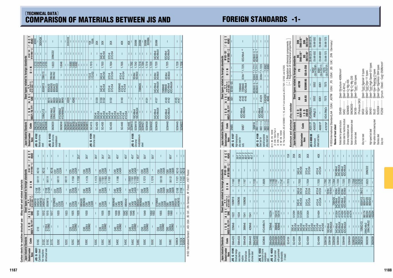
’TECHNICAL DATA»
COMPARISON OF MATERIALS BETWEEN JIS AND FOREIGN STANDARDS -1-St
eel t
ypes
rela
ted
to fo
reig
n st
anda
rds
Chro
me
stee
l
steel
Nick
el-ch
rom
e
steel
moly
bden
umNi
ckel-
chro
me
Japa
n Ind
ustri
al S
tand
ards
Stand
ard nu
mber
Name
Code
Chro
me
mol
ybde
num
stee
l
Code
Name
Stand
ard nu
mber
Stee
l typ
es re
late
d to
fore
ign
stan
dard
sJa
pan I
ndus
trial
Sta
ndar
dsCa
rbon
ste
els
for m
achi
ne s
truct
ual u
seC
Allo
y st
eel a
nd re
late
d m
ater
ials
Carb
on s
teel
for m
achi
nest
ruct
ual u
se
Stee
lCSt
ruct
ureC
400N
/mm
2
Stee
lC0.
45%
CSt
eelC
CrC
Mo
435
Stee
lCNiC
CrC
Mo
220
Stee
lCTo
olC10
5 ty
pes
Stee
lCTo
olCSp
ecia
lC3
type
sSt
eelC
ToolC
DiesC
11 ty
pes
Stee
lCTo
olCHi
gh S
peedC
51 ty
pes
Stee
lCUs
eCBe
arin
gC2
type
sSt
eelC
UseC
Stai
nles
sC30
4 ty
pes
Ferr
um(
Stee
l)C
CastC
250N
/mm
2
GIS
O(In
tern
atio
nal S
tand
ard)
,AA(
USA)
,AST
M(
USA)
,FS(
USA)
,BS(
UK)
,DIN(
Germ
any)
Nam
e of
tool
ste
el
Rolle
d stee
l for g
enera
l stru
cture
Carbo
n stee
l for m
achin
e stru
cture
Chrom
e moly
bden
um st
eel
Nicke
l chro
me m
olybd
enum
stee
lCa
rbon t
ool s
teel
Alloy
tool
steel
W
High-s
peed
tool
steel
High-c
arbon
chrom
e bea
ring s
teel
Stainl
ess s
teel
Gray
iron
2) 2)3)3)
42CrM
o4
40CrMo
V4740C
rMoV47
1)40
CrMoV
4-6
1)40
CrMoV
4-6
4)40
CrMoV
4-6
4)40
CrMoV
4-6
42CrMo
41
)42
CrM
o44
)42
CrM
o4
--- -
-------
--
-
709M
4070
8M40
--
BS15
06-
625
4145
4140
4340
E434
0H
4142
H
--4142
501
--
42Cr
Mo4
42Cr
MoS
4
42Cr
Mo4
42Cr
MoS
4
---
SNB2
4-1~
5SN
B23-
1~5
SNB2
2-1~
5
SNB2
1-1~
5SN
B16
SNB7
SNB5
JIS G 41
07
JIS G 41
08
SAE
4543
oD
I N
A I
S I
I S
OCo
deNa
meSta
ndard
numb
erSt
eel t
ypes
rela
ted
to fo
reig
n st
anda
rds
Japa
n Ind
ustri
al S
tand
ards
O
C T
High-t
empe
rature
alloy s
teel fo
r bo
lts
Stee
l bar
forsp
ecial
-pur
pose
alloy
stee
l bolt
1.72
25
1.77
111.
7711
1.72
23
1.65
621.
6565
-
EN AW
-505
2EN
AW-5
052
-EN
AW-20
17A
EN AW
-2017
A- 50
5250
52-
AlM
g2.5
EN AW
-606
1EN
AW-6
061
6061
(QQ-
A-25
0/11F
)
5052
(QQ-
A-25
0/8F)
7075
(QQ-
A-25
0/12F
)
6061
6061
-
EN AW
-707
5EN
AW-7
075
7075
7075
AlZn
5.5M
gCu
AlCu4
MgSi(
A)A2
017P
A505
2P
A606
1P
A707
5P
JIS H
400
0:88
6361
:90
AA:9
3
AA
B209
M:9
5
ASTM
QQ-A
-250
FSI
S O
209:
89I
S O
EN48
5-2:95
**BS
EN57
3-3:95
*BS
EN48
5-2:95
**DI
N
EN57
3-3:94
*DI
NCo
de
Stee
l typ
es re
late
d to
fore
ign
stan
dard
sJa
pan I
ndus
trial
Sta
ndar
ds
Alum
inum
shee
t and
bars
Alum
inum
and
alu
min
um a
lloy
exte
nder
*:Re
gula
tion
of c
hem
ical
com
pone
nts
**:
Regu
latio
n of
mec
hani
cal p
rope
rties
()
Name
Stand
ard nu
mber
683/
1,10
, 115)
B S
970 P
art
1,3
BS E
N 10
083-
1,2
NF A3
5-55
1NF
EN 10
083-
1,2
G1) BS
EN
102
59
2) DI
N 1
654
Part
4
3) DI
N 1
7240
4) NF
EN
102
59
5) Th
e tra
nsla
tion
JIS
of IS
O683-
1, 1
0, a
nd 1
1 ar
e is
sued
as
JIS
G 75
01, G
7502
, and
G75
03.
SS40
0EEE
S45CEEE
SCM
435EE
SNCM
220E
SK10
5EEE
(Pr
evio
us S
K3)
SKS3EEE
SKD1
1EEE
SKH5
1EEE
SUJ2EEE
SUS3
04EE
FC25
0EEE
steel
molyb
denum
Alumi
num
chrom
e
Stru
ctual
use
and m
anga
nese
chro
me st
eel
mach
ine
nese
stee
l for
Struc
tual m
anga
-
Stru
ctual
steel
with
guara
nteed
hard
enab
ility
(H
steel)
Japa
n Ind
ustri
al S
tand
ards
Stee
l typ
es re
late
d to
fore
ign
stan
dard
sSta
ndard
numb
erCo
de
GIS
O(Int
ernati
onal
Stan
dard)
, AIS
I(US
A), B
S(UK)
, DIN(
Germ
any)
, NF(
Franc
e), Γ
OCT(
Russ
ia)
-
25o
30o
30o
35o
35o
40o
40o
45o
45o
50o
50o
60o- - - - - - - - - -
XC18-
XC12
XC10
- --- - -- --
C22
C22E
C22R
C25
C30
C30E
C30R
C35
C40
C40E
C40R
C45
C45E
C45R
C55
C55E
C55R
C60
C60E
C60R
C10E
C15E
C50
C50E
C50R
C35E
C35R
C25E
C25R
--- -- -
C22
C22E
C22R
C25
C30
C30E
C30R
C35
C40
C40E
C40R
C45
C45E
C45R
C55
XC12
XC18
C55E
C55R
C60
C60E
C60R
XC10
C50
C50E
C50R
C35E
C35R
C25E
C25R
--- - - - -
070M
20C2
2C2
2EC2
2R
C25
080A
3008
0M30
C30
C30E
C30R
C35
080M
40C4
0C4
0EC4
0R08
0A42
C45
C45E
C45R
080A
4708
0M50
070M
55C5
5C5
5EC5
5RC6
0C6
0EC6
0R04
5A10
045M
10
C50
C50E
C50R
C35E
C35R
C25E
C25R
C15R
C15E
C10E
C10R
-
055M
1504
0A12
045M
10
040A
1004
5A10
1020
1023
1025
1029
1030
- 1035
1038
1039
1040
1042
1043
1045
1046
- 1049
1050
1053
1055
1059
1060
- - -1017
1015
1012
1010
- - - - - - - -- - --
C25
C25E
4C2
5M2
C30
C30E
4C3
0M2
C35
C35E
4C3
5M2
C40
C40E
4C4
0M2
C45
C45E
4C4
5M2
C50
C50E
4C5
0M2
C55
C55E
4C5
5M2
C60
C60E
4C6
0M2
C15E
4C1
5M2
-
C10
S20C
S22C
S25C
S28C
S30C
S33C
S35C
S38C
S40C
S43C
S45C
S48C
S50C
S53C
S55C
S58C
S09C
K
S15C
KS2
0CK
S17C
S15C
S12C
S10C
JIS G 40
51
683/
1,10
, 115)
SAE
4543
oD
I N
A I
S I
O
C T
-
1.0301/1
.1121
1.0401/1
.1141
1.0402/1
.1151
1.0402/1
.1151
1.0535/1
.1203
1.0601/1
.1221
1.11
58
1.11
58
1.11
78
1.11
73
1.11
81
1.11
86
1.11
91
1.12
13
1.12
10
1.11
211.
1141
1.11
51
1.02
011.
1181
1.11
83
1.05
031.
1191
1.11
93
- -
B S
970 P
art
1,3
BS E
N 10
083-
1,2
NF A3
5-55
1NF
EN 10
083-
1,2
---
35XM-
30XM
A20
XM-20
XM
20XM-
45X
40X
35X
30X
20X----- 15XA
15X-------
20XH2
M(20X
HM)
30XH
3A-40XH
--------- -- - - - - - - - - -
20NC
D2
----
--------
41Cr
S441
Cr4
------------ ---
--
42Cr
MoS
4
708M
40
42Cr
Mo4
42Cr
MoS4
42Cr
Mo4
34Cr
MoS
4
709M
40
34Cr
Mo4
42Cr
MoS
442
CrM
o4
34Cr
MoS
434
CrM
o434
CrMo
S434
CrMo
4
18Cr
MoS4
18Cr
Mo4
--70
8M20
- ---
41Cr
441
CrS4
530M
40
37Cr
437
CrS4
37Cr
437
CrS4
37Cr
437
CrS4
34Cr
S434
Cr4
34Cr
S4
15Ni
Cr13
20NiC
rMo2
20NiC
rMo2
34Cr
434
CrS4
34Cr
4
17Cr
S317
Cr3
-------- ----
805M
2280
5A22
805A
2080
5M20
-65
5M13---
-41
47
4142
4137
4145
4140-
4131----
5140
5132
5120- -
4340-
4320-
5132
5130
8622
8615
8640
8620
8637
8617 -- -- -- -- --
--------41
CrS4
42Cr
MoS
4
34Cr
MoS
4
42Cr
Mo4
34Cr
Mo4
18Cr
MoS
418
CrM
o4
41Cr
437
CrS4
37Cr
434
CrS4
34Cr
4
34Cr
434
CrS4
34Cr
S434
Cr4
20Cr
S420
Cr4- ---------
41Cr
NiM
oS2
20Ni
CrM
oS2
41Cr
NiM
o2
20Ni
CrM
o2
-15
NiCr
13---
SCM
822
SCM
445
SCM
440
SCM
435
SCM
432
SCM
430
SCM
421
SCM
420
SCM
418
SCM
415
SCr4
45
SCr4
40
SCr4
35
SCr4
30
SCr4
20
SCr4
15
SNCM
815
SNCM
630
SNCM
625
SNCM
616
SNCM
447
SNCM
439
SNCM
431
SNCM
420
SNCM
415
SNCM
240
SNCM
220
SNC8
36SN
C815
SNC6
31SN
C415
SNC2
36
JIS G 41
05
JIS G 41
04
JIS G 41
02
JIS G 41
03
A I
S I
D I
No
4543
SAE
683/
1,10
, 115)
O
C T
1.57
101.
5732
1.57
361.
5752
1.57
55
1.65
23
1.65
46
1.65
801.
6565
1.65
82
1.70
15
1.70
33
1.70
34
1.70
35
1.72
42
1.72
18
1.72
62
1.72
641.
7218
1.72
20
1.72
20
1.72
25
1.72
281.
7258
- - - - - - - -
B S
970 P
art
1,3
BS E
N 10
083-
1,2
NF A3
5-55
1NF
EN 10
083-
1,2
- - - - - - - - - ---40X
45o
240o
2
- - - - -
40o
235o
235o
230o
2
35X
30X
20X
15X
- -- --
20NC
D2
--- ----- -- - --- - - - - --- - - -
---- - -
34CrM
o434C
rMoS
434
CrM
o434
CrM
oS4
--
41Cr
S4
18CrM
o418C
rMoS
4
15NriC
r13
41Cr
441
CrS4
41Cr
4
37Cr
S437
Cr4
37Cr
S437
Cr4
------- - --- - - - -
34Cr
4
805H
2280
5H20
-
805H
1765
5H13
----
42Cr
Mo4
42Cr
MoS
442C
rMo4
42CrM
oS4
42Cr
Mo4
42Cr
MoS
4
34Cr
Mo4
34Cr
MoS
4
708H
20
--
41Cr
441
CrS4
37Cr
437
CrS4
150M
36
150M
19
150M
36
-- -- ----- ---
34Cr
434
CrS4
34Cr
S434
Cr4
34Cr
S4
8622
H
8617
H
4320
H
8620
H
-------
5140
H
5135
H
4147
H41
45H
4142
H41
40H
4137
H41
35H
5132
H51
30H
5120
H
---15
41H
1541
H-
1522
H
---
1541
1541
1534
1522
20Ni
CrM
oS2
20Ni
CrM
o2
-
15Ni
Cr13
------41
CrS4
41Cr
437
CrS4
37Cr
437
CrS4
37Cr
4
34Cr
434
CrS4
18Cr
MoS
418
CrM
o4
34Cr
S434
Cr4
42Cr
MoS
442
CrM
o434
CrM
oS4
34Cr
Mo4
20Cr
S420
Cr4
- --42
Mn6
36M
n6-
22M
n6
41Cr
AIM
o74
--
42M
n6
36M
n6
-
22M
n6
SNCM
420H
SNCM
220H
SNC8
15H
SNC6
31H
SNC4
15H
SCM
822H
SCM
445H
SCM
440H
SCM
435H
SCM
420H
SCM
418H
SCM
415H
SCr4
40H
SCr4
35H
SCr4
30H
SCr4
20H
SCr4
15H
SMnC
443H
SMnC
420H
SMn4
43H
SMn4
38H
SMn4
33H
SMn4
20H
SACM
645
SMnC
443
SMnC
420
SMn4
43
SMn4
38
SMn4
33
SMn4
20
JIS G 40
52
JIS G 42
02
JIS G 41
06
Name
I S
OA
I S
ID
I N
o O
C T
4543
SAE
683/
1,10
, 115)
1.11
60
1.11
66
1.11
67
1.11
33
1.85
09
1.11
601.
1166
1.11
67
1.71
47
1.70
15
1.70
33
1.70
34
1.70
35
1.72
62
1.72
42
1.72
641.
7220
1.72
25
1.72
28
1.72
581.
5732
1.57
361.
5752
1.65
23
- - - - - -
B S
970 P
art
1,3
BS E
N 10
083-
1,2
NF A3
5-55
1NF
EN 10
083-
1,2
I S
OI
S O
PD-14 2nd
Stee
l typ
es re
late
d to
fore
ign
stan
dard
sSt
eel t
ypes
rela
ted
to fo
reig
n st
anda
rds
Code
Name
Stand
ard nu
mber
Japa
n Ind
ustri
al S
tand
ards
Code
Name
Stand
ard nu
mber
Japa
n Ind
ustri
al S
tand
ards
Stee
l typ
es re
late
d to
fore
ign
stan
dard
s
Code
Stand
ard nu
mber
Japa
n Ind
ustri
al S
tand
ards
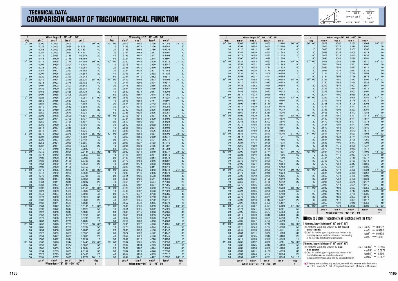
11861185
0B00'1020304050
1B00'1020304050
2B00'1020304050
3B00'1020304050
4B00'1020304050
5B00'1020304050
6B00'1020304050
7B00'1020304050
8B00'1020304050
9B00'1020304050
10B00'1020304050
11B00'1020304050
.0000
.0029
.0058
.0087
.0116
.0145
.0175
.0204
.0233
.0262
.0291
.0320
.0349
.0378
.0407
.0436
.0465
.0494
.0523
.0552
.0581
.0610
.0640
.0669
.0698
.0727
.0756
.0785
.0814
.0843
.0872
.0901
.0929
.0958
.0987
.1016
.1045
.1074
.1103
.1132
.1161
.1190
.1219
.1248
.1276
.1305
.1334
.1363
.1392
.1421
.1449
.1478
.1507
.1536
.1564
.1593
.1622
.1650
.1679
.1708
.1736
.1765
.1794
.1822
.1851
.1880
.1908
.1937
.1965
.1994
.2022
.2051
1.00001.00001.00001.00000.9999
.9999
.9998
.9998
.9997
.9997
.9996
.9995
.9994
.9993
.9992
.9990
.9989
.9988
.9986
.9985
.9983
.9981
.9980
.9978
.9976
.9974
.9971
.9969
.9967
.9964
.9962
.9959
.9957
.9954
.9951
.9948
.9945
.9942
.9939
.9936
.9932
.9929
.9925
.9922
.9918
.9914
.9911
.9907
.9903
.9899
.9894
.9890
.9886
.9881
.9877
.9872
.9868
.9863
.9858
.9853
.9848
.9843
.9838
.9833
.9827
.9822
.9816
.9811
.9805
.9799
.9793
.9787
.0000
.0029
.0058
.0087
.0116
.0145
.0175
.0204
.0233
.0262
.0291
.0320
.0349
.0378
.0407
.0437
.0466
.0495
.0524
.0553
.0582
.0612
.0641
.0670
.0699
.0729
.0758
.0787
.0816
.0846
.0875
.0904
.0934
.0963
.0992
.1022
.1051
.1080
.1110
.1139
.1169
.1198
.1228
.1257
.1287
.1317
.1346
.1376
.1405
.1435
.1465
.1495
.1524
.1554
.1584
.1614
.1644
.1673
.1703
.1733
.1763
.1793
.1823
.1853
.1883
.1914
.1944
.1974
.2004
.2035
.2065
.2095
343.77171.89114.59
85.94068.75057.29049.10442.96438.18834.36831.24228.63626.43224.54222.90421.47020.20619.08118.07517.16916.35015.60514.92414.30113.72713.19712.70612.25111.82611.43011.05910.71210.38510.078
9.78829.51449.25539.00988.77698.55558.34508.14437.95307.77047.59587.42877.26877.11546.96826.82696.69126.56066.43486.31386.19706.08445.97585.87085.76945.67135.57645.48455.39555.30935.22575.14465.06584.98944.91524.84304.7729
N 90B00'5040302010
89B00'5040302010
88B00'5040302010
87B00'5040302010
86B00'5040302010
85B00'5040302010
84B00'5040302010
83B00'5040302010
82B00'5040302010
81B00'5040302010
80B00'5040302010
79B00'50403020
78B10
12B00'1020304050
13B00'1020304050
14B00'1020304050
15B00'1020304050
16B00'1020304050
17B00'1020304050
18B00'1020304050
19B00'1020304050
20B00'1020304050
21B00'1020304050
22B00'1020304050
23B00'1020304050
.2079
.2108
.2136
.2164
.2193
.2221
.2250
.2278
.2306
.2334
.2363
.2391
.2419
.2447
.2476
.2504
.2532
.2560
.2588
.2616
.2644
.2672
.2700
.2728
.2756
.2784
.2812
.2840
.2868
.2896
.2924
.2952
.2979
.3007
.3035
.3062
.3090
.3118
.3145
.3173
.3201
.3228
.3256
.3283
.3311
.3338
.3365
.3393
.3420
.3448
.3475
.3502
.3529
.3557
.3584
.3611
.3638
.3665
.3692
.3719
.3746
.3773
.3800
.3827
.3854
.3881
.3907
.3934
.3961
.3987
.4014
.4041
.9781
.9775
.9769
.9763
.9757
.9750
.9744
.9737
.9730
.9724
.9717
.9710
.9703
.9696
.9689
.9681
.9674
.9667
.9659
.9652
.9644
.9636
.9628
.9621
.9613
.9605
.9596
.9588
.9580
.9572
.9563
.9555
.9546
.9537
.9528
.9520
.9511
.9502
.9492
.9483
.9474
.9465
.9455
.9446
.9436
.9426
.9417
.9407
.9397
.9387
.9377
.9367
.9356
.9346
.9336
.9325
.9315
.9304
.9293
.9283
.9272
.9261
.9250
.9239
.9228
.9216
.9205
.9194
.9182
.9171
.9159
.9147
.2126
.2156
.2186
.2217
.2247
.2278
.2309
.2339
.2370
.2401
.2432
.2462
.2493
.2524
.2555
.2586
.2617
.2648
.2679
.2711
.2742
.2773
.2805
.2836
.2867
.2899
.2931
.2962
.2994
.3026
.3057
.3089
.3121
.3153
.3185
.3217
.3249
.3281
.3314
.3346
.3378
.3411
.3443
.3476
.3508
.3541
.3574
.3607
.3640
.3673
.3706
.3739
.3772
.3805
.3839
.3872
.3906
.3939
.3973
.4006
.4040
.4074
.4108
.4142
.4176
.4210
.4245
.4279
.4314
.4348
.4383
.4417
4.70464.63824.57364.51074.44944.38974.33154.27474.21934.16534.11264.06114.01083.96173.91363.86673.82083.77603.73213.68913.64703.60593.56563.52613.48743.44953.41243.37593.34023.30523.27093.23713.20413.17163.13973.10843.07773.04753.01782.98872.96002.93192.90422.87702.85022.82392.79802.77252.74752.72282.69852.67462.65112.62792.60512.58262.56052.53862.51722.49602.47512.45452.43422.41422.39452.37502.35592.33692.31832.29982.28172.2637
78B00'5040302010
77B00'5040302010
76B00'5040302010
75B00'5040302010
74B00'5040302010
73B00'5040302010
72B00'5040302010
71B00'5040302010
70B00'5040302010
69B00'5040302010
68B00'5040302010
67B00'50403020
66B10
24B00'1020304050
25B00'1020304050
26B00'1020304050
27B00'1020304050
28B00'1020304050
29B00'1020304050
30B00'1020304050
31B00'1020304050
32B00'1020304050
33B00'1020304050
34B00'1020304050
35B00'1020304050
.4067
.4094
.4120
.4147
.4173
.4200
.4226
.4253
.4279
.4305
.4331
.4358
.4384
.4410
.4436
.4462
.4488
.4514
.4540
.4566
.4592
.4617
.4643
.4669
.4695
.4720
.4746
.4772
.4797
.4823
.4848
.4874
.4899
.4924
.4950
.4975
.5000
.5025
.5050
.5075
.5100
.5125
.5150
.5175
.5200
.5225
.5250
.5275
.5299
.5324
.5348
.5373
.5398
.5422
.5446
.5471
.5495
.5519
.5544
.5568
.5592
.5616
.5640
.5664
.5688
.5712
.5736
.5760
.5783
.5807
.5831
.5854
.9135
.9124
.9112
.9100
.9088
.9075
.9063
.9051
.9038
.9026
.9013
.9001
.8988
.8975
.8962
.8949
.8936
.8923
.8910
.8897
.8884
.8870
.8857
.8843
.8829
.8816
.8802
.8788
.8774
.8760
.8746
.8732
.8718
.8704
.8689
.8675
.8660
.8646
.8631
.8616
.8601
.8587
.8572
.8557
.8542
.8526
.8511
.8496
.8480
.8465
.8450
.8434
.8418
.8403
.8387
.8371
.8355
.8339
.8323
.8307
.8290
.8274
.8258
.8241
.8225
.8208
.8192
.8175
.8158
.8141
.8124
.8107
.4452
.4487
.4522
.4557
.4592
.4628
.4663
.4699
.4734
.4770
.4806
.4841
.4877
.4913
.4950
.4986
.5022
.5059
.5095
.5132
.5169
.5206
.5243
.5280
.5317
.5354
.5392
.5430
.5467
.5505
.5543
.5581
.5619
.5658
.5696
.5735
.5774
.5812
.5851
.5890
.5930
.5969
.6009
.6048
.6088
.6128
.6168
.6208
.6249
.6289
.6330
.6371
.6412
.6453
.6494
.6536
.6577
.6619
.6661
.6703
.6745
.6787
.6830
.6873
.6916
.6959
.7002
.7046
.7089
.7133
.7177
.7221
2.24602.22862.21132.19432.17752.16092.14452.12832.11232.09652.08092.06552.05032.03532.02042.00571.99121.97681.96261.94861.93471.92101.90741.89401.88071.86761.85461.84181.82911.81651.80401.79171.77961.76751.75561.74371.73211.72051.70901.69771.68641.67531.66431.65341.64261.63191.62121.61071.60031.59001.57981.56971.55971.54971.53991.53011.52041.51081.50131.49191.48261.47331.46411.45501.44601.43701.42811.41931.41061.40191.39341.3848
66B00'5040302010
65B00'5040302010
64B00'5040302010
63B00'5040302010
62B00'5040302010
61B00'5040302010
60B00'5040302010
59B00'5040302010
58B00'5040302010
57B00'5040302010
56B00'5040302010
55B00'50403020
54B10
36B00'1020304050
37B00'1020304050
38B00'1020304050
39B00'1020304050
40B00'1020304050
41B00'1020304050
42B00'1020304050
43B00'1020304050
44B00'1020304050
45B00'
54B00'5040302010
53B00'5040302010
52B00'5040302010
51B00'5040302010
50B00'5040302010
49B00'5040302010
48B00'5040302010
47B00'5040302010
46B00'5040302010
45B00'
.5878
.5901
.5925
.5948
.5972
.5995
.6018
.6041
.6065
.6088
.6111
.6134
.6157
.6180
.6202
.6225
.6248
.6271
.6293
.6316
.6338
.6361
.6383
.6406
.6428
.6450
.6472
.6494
.6517
.6539
.6561
.6583
.6604
.6626
.6648
.6670
.6691
.6713
.6734
.6756
.6777
.6799
.6820
.6841
.6862
.6884
.6905
.6926
.6947
.6967
.6988
.7009
.7030
.7050
.7071
.8090
.8073
.8056
.8039
.8021
.8004
.7986
.7969
.7951
.7934
.7916
.7898
.7880
.7862
.7844
.7826
.7808
.7790
.7771
.7753
.7735
.7716
.7698
.7679
.7660
.7642
.7623
.7604
.7585
.7566
.7547
.7528
.7509
.7490
.7470
.7451
.7431
.7412
.7392
.7373
.7353
.7333
.7314
.7294
.7274
.7254
.7234
.7214
.7193
.7173
.7153
.7133
.7112
.7092
.7071
.7265
.7310
.7355
.7400
.7445
.7490
.7536
.7581
.7627
.7673
.7720
.7766
.7813
.7860
.7907
.7954
.8002
.8050
.8098
.8146
.8195
.8243
.8292
.8342
.8391
.8441
.8491
.8541
.8591
.8642
.8693
.8744
.8796
.8847
.8899
.8952
.9004
.9057
.9110
.9163
.9217
.9271
.9325
.9380
.9435
.9490
.9545
.9601
.9657
.9713
.9770
.9827
.9884
.99421.0000
1.37641.36801.35971.35141.34321.33511.32701.31901.31111.30321.29541.28761.27991.27231.26471.25721.24971.24231.23491.22761.22031.21311.20591.19881.19181.18471.17781.17081.16401.15711.15041.14361.13691.13031.12371.11711.11061.10411.09771.09131.08501.07861.07241.06611.05991.05381.04771.04161.03551.02951.02351.01761.01171.00581.0000
ex.)sin 5B=10.0872ex.)cos5B=10.9962ex.)tan 5B=00.0875ex.)cot 5B=11.430
ex.)sin 85B=00.9962ex.)cos85B=00.0872ex.)tan 85B=11.430ex.)cot 85B=00.0875
a
b
cP
a = ,
b = aCcosP ,
c = aCsinP ,bCtanP
cosPb
sinPc
tanPc
〔TECHNICAL DATA〕COMPARISON CHART OF TRIGONOMETRICAL FUNCTION
When deg.(degree)is between 0B00'and 45B00'
IHow to Obtain Trigonometrical Functions from the Chart
When deg.(degree)is between 45B00'and 90B00'
qLocate the target deg. value in the left-handed sideP column.wCheck the required type of trigonometrical function in the chart's top row, and obtain the real number corresponding to the deg. value from the appropriate column.
qLocate the target deg. value in the right most column.wCheck the required type of trigonometrical function in the chart's bottom row, and obtain the real number corresponding to the deg. value from the appropriate column.
If the deg value contains any fractions, convert it into a degree and minute value. ex.)5.5Bstands for 5B30'(5 degrees 30 minutes).(1 degree=60 minutes)
degP
cosPWhen deg=54B10'~66B00'
sinP cotP tanP
P
deg sinPWhen deg=24B00'~35B50'
cosP tanP cotPP
deg sinPWhen deg=36B00'~45B00'
cosP tanP cotPP
deg sinPWhen deg=12B00'~23B50'
cosP tanP cotPP
deg sinPWhen deg=0B00'~11B50'
cosP tanP cotP
degcosPWhen deg=78B10'~90B00'
sinP cotP tanPP
degP
cosPWhen deg=66B10'~78B00'
sinP cotP tanP
When deg=45B00'~54B00'
cosP sinP cotP tanP degP
PD-13 1st
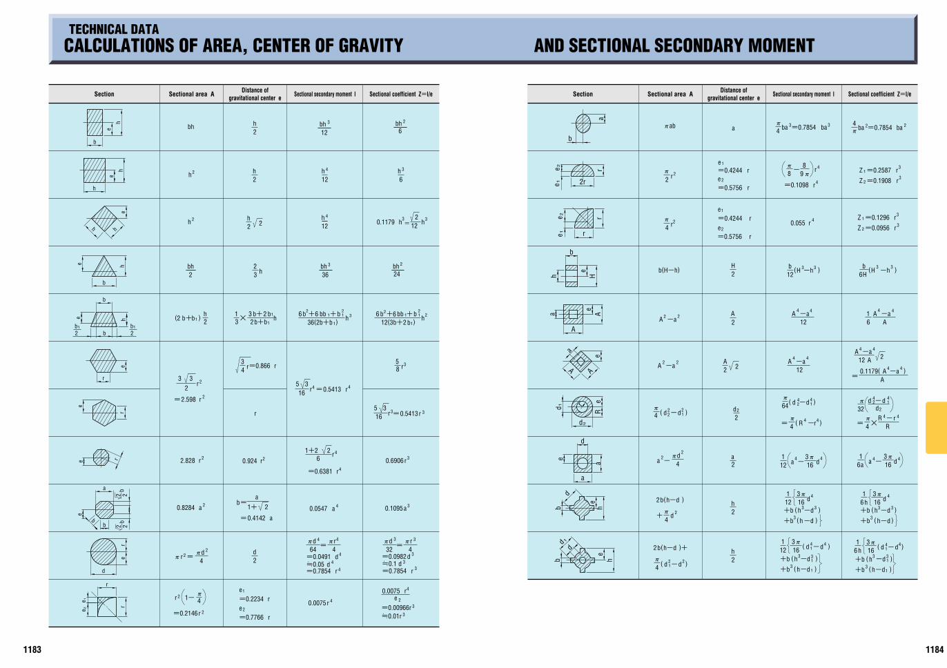
2 2b
b
ee
b
h
e
h h
hh
b
he
b
h
bb1
2
e
r
e
e
r
21b
2e
rr
e
d
22
b
e
b
a
re
1
2
2
2
22
2
2
2
43
3
2
4
4
4
4
33
3
334 4
4 3
3
4
422
4
3
23
334
4
4
3
3
3
3
2
2
2
r
=0.01r=0.00966r
re
0.00751
r
r
=0.7766e=0.2234e
1- Q
4
=0.2146r
r
Q
32=
4Qd r
=0.0982dd=0.1
=0.7854 rr=0.7854=0.05 d
d=0.0491
rd
d
Q
4=
64Q
=Q
4Q
b=
0.4142
a1+ 2
a=
=0.6381 r
r21+2
0.0075r
0.6906r
0.1095aa0.05470.8284 a
0.924 rr2.828
2d
6
b+
3
r2.598=
r2
33
16 r =0.5413 r5
50.5413r=r16
3
r=0.866r34
b2h1bb
1b+6 b
12(36
)+
2+b2
232b 1+
2+
)6
36(2b+bb6
1
bb 1 hh1b
1b+b2b+
23
31 M2
h) 1b(2
85
r
r
212
bh2
bh2436
bh
= h0.1179
h23
22h h
12
h612
h
6bhbh
12
h2
2h
h
h
bh
e 1
r
12e
e
r
r
12
2r
r
ee
b
a
d
b
eh
he
b
d
e
a
a
d
d
d
Rer
e
a
A A
a A
A
eHh
e
b
1
2
1
2
4
3
3
4
3
3
4
3
4
3
44
r44
44
2
2
2
22
22 2
4 4
44
33
44
4 4
44
44
4
)33
4
3
-dh(3
4
3 3
3
32
2
4
2
2
2 2
2
2
33
4
44
22
22
3
3
33
4
4
)
ab
( 1- )d d
+b 1 )
)-dh(+b 11
dd )-1(
+b121
163Q
(h -d )
)1-dh(+b
3Q16
16 h
h+b61
d163Q
(h -d)-dh(+b+b (h-d
)-dh(
3Q16 d
112+b
4Q
( 1- )d d
2 (h-d )+b
4Q
d+
b )h-d(2
a1
63Q
- 16a dda 16-3Q
121d
- 4Q
a
M R
ddd 1-Q
32
4Q -R r
== R )-(Q
4
64Q
( 2- 1 )d d
dd )1-(Q
4
)A=
0.1179( -aA
A-aA
12 2A
12-a
A -a
61 A
A-a-a
12A
-aA
H6b (H -h ))-hH(b
12
Z 1=0.1296 r
r=0.09562Z
Z 2=0.1908 r
r=0.25871Z
ba =0.7854 baQ4Q
4 ba=0.7854ba
Q-
Q
8r
=0.1098 r
98
1
r
r
=0.5756e=0.4244e
e=0.4244e=0.5756
r
r
1
d2
2a
h2
2h
0.055 rrQ
4
Q
2Q
r
a
22A
A2
2H
b(H-h)
d
11841183
h
〔TECHNICAL DATA〕CALCULATIONS OF AREA, CENTER OF GRAVITY AND SECTIONAL SECONDARY MOMENT
Section Sectional area A Distance ofgravitational center e Sectional secondary moment I Sectional coefficient Z=I/e Sectional coefficient Z=I/eSectional secondary moment IDistance of
gravitational center eSectional area ASection
PD-12 1st

V=Q4 d2h
d4Q 2=
h2
1+h2
3V= A=h6h arn
r
a
n
3
6Qh
=
V=Qh(3r-h)2
(3a2+h2)
QabcV=
V=
34
Qab43
2
4
=Qth(D-t)
V=Q h(D2-d2)
=Qth(d+t)
(A+a+ Aa)hV= 3
2V= Qr32h
2 h
DdQ4
V=2Q2 Rr 2
2
2
2
=19.739Rr
=
=2.4674Dd
=2.0944r
=1.0472r
rV=Q32h
2h
3
6Q
= d3
V= 4Qr
=0.5236d 3
3=4.1888r 3
QhV= (3a62+3b 2+h2)
(2DQ V= 122+d2)
V=0.209 2 Dd+1/4d 2)(2D
[g/cm ] [Kgf/mm ]2
1Kgf/mm =9.80665M10 Pa2 6
3
SUS304
SKD11
7.85
7.85
14.1
7.3
8.0
8.9
8.4
2.7
2.8
4.5
7500~10500
56000
21000
21000
19700
11700
10300
6900
7200
10600
9.2~11.8
6.0
11.7
8.07 23300 10.1
11.7
17.3
17.6
20.8
23.6
23.6
8.4
h1
d
hh2 d t
D
h
D
d
r
R
r
rh
a
h h
a c
b
d D
D
h
r
a
h
r a
h
b
2
r
r
r
FD
L
Q4Q4
[M10 /A]-6
100F
2
0.117[20A]
[120A]
11821181
Pt=‰tMAsEEE(1)
=112/5=22.4[kgf/mm2]
=Qd2‰t/4EE(2)
As=Pt/‰t=200/22.4=8.9[mm2]
345
121515
565
8109
13.111.310.68.97.46.76.15.85.24.7
M 4M 5M 6M 8M10M12M14M16M20M24
8.78 14.2 20.1 36.6 58 84.3115157245353
114160213326429565702911
12741659
9.17.87.48.77.36.565.75.14.7
79111149318423548690895
12501659
12.9
kgf/mm2 kgf kgf/mm2 kgf
10.9
=46.6/12=3.9[kgf/mm2]
A=(M-P)QL=(30-1.5)QM12=1074[mm2]
=46.6
P=AMÍ
D=
=QD2Í/4
(4P)/(QÍ)
=
—7.3(4M800)/(3.14M19.2)
=120M0.8/5=19.2[kgf/mm2]
E=
ð = = 1000M6078.5M21000
PLAðPLAE
L
ð
Pkgf
M
P
P
= M1.62M5M7.85
—79[g]
—0.036mmF10
P=ÍtMA. =3.9M107.4 =4190[kgf]
〔TECHNICAL DATA〕STRENGTH OF BOLTS, SCREW PLUGS AND DOWEL PINS
Pt :Tensile load in the axial direction[kgf]‰b:Yield stress of bolt[kgf/mm2]
‰t :Allowable stress of bolt[kgf/mm2]
(‰t=‰b/safety factor Å)As:Effective sectional area of bolt[mm2]
d :Effectiveness of bolt(core diameter)[mm]
ISafety factor Å of Unwin based on tensile strength
SteelCast iron
Copper, soft metal
Static load Impact loadPulsatingRepeated load
ReversedMaterial
Reference strength:Yield stress for ductile materials Fracture stress for brittle materials
Allowable stress= Reference strength
Safety factorÅ
(Example)Find a suitable size when a socket head cap screw receives tensile load of P=200kgf repeatedly(pulsating).
From equation(1)
(Socket head cap screw material:SCM435, 38~43HRC, strength class:12.9)
Find an effective sectional area greater than this value from the table at the right. M4 of 14.2’mm2»will be the selection. If fatigue strength is taken into account, M6 of allowable load 213kgf in 12.9 should be selected.
2)Selection must be based on fatigue strength for the bolts such as the stripper bolt which receives impact load from tension. (As the above example, 200kgf load is applied. Stripper bolt material:SCM435, 33~38HRC, strength class 10.9)
From the table at the right, M8 of 318’kgf»is found when allowable load of strength class 10.9 is over 200kgf. Accordingly, MSB10 having M8 screw and axial diameter of 10mm is the selection. Use dowel pins when shearing load is applied.
IStrength of screw plugsFind allowable load P when screw plug MSW30 receives impact load.(MSW30 material:S45C, tensile strength‰b for 34~43HRC is 65kgf/mm2.)If MSW breaks by shearing force applied to the core diameter part, allowable load
Find the allowable shearing force based on the core diameter of internal thread if tapping is made of soft material.
Shearing sectional area A=Core diameter d1MQML
Yield stress—0.9MTensile strength‰b=0.9M65=58.2Shearing stress—0.8MYield stress
Allowable shearing stress Qt=Shearing stress/safety factor 12
(Core diameter d1—M-P)
IStrength of dowel pinsFind a suitable size when a dowel pin receives 800kgf repetitive(pulsating)shearing load.(Dowel pin material:SUJ2CHardness 58HRC or more)
For MS dowel pin, select D8 or larger size. When larger size dowel pins are used, tools and stocks can be reduced.
‰b for yield stress of SUJ2=120[kgf/mm2]
Allowable shearing strengthÍ=‰bM0.8/safety factorÅ
The calculations shown above are only examples of finding strength. For actual calculation, various conditions, such as accuracy of inter-hole pitch, perpendicularity of holes, surface roughness, circularity, plate materials, parallelism, quenching, precision of press machine, quantity of production, and wear of tools, should be taken into account. Use these examples as a reference for calculating strength. (They are not guaranteed values.)
〔TECHNICAL DATA〕CALCULATION OF CUBIC VOLUME
IHow to calculate the weightWeight[g]=Volume[cm3]MDensity
Example:Soft steel
FD=16 L=50mm, the weight is:
W= D2MLMDensity
IMethod for finding changes dimensions due to thermal expansionExample:SKD11
FD=2 The volume of dimension change Î when a pin of L=100mm is heated to 2A is Î=Coefficient of thermal expansionMTotal lengthMChange in temperature =11.7M10-6M100mmM100A =0.117[mm]
Density Young's modulusE Thermal expansion coefficient
IFinding strain with Young's modulus E’Example»Find amount of strainð when load P=1000kgf is applied to F10ML60 pin.(Material:SKD11)
Sectional area A=Q4 D2
ICharacteristics of Metals
Material
Duralumin A7075
Aluminum A1100
Titanium
Cemented carbide V30
Oxygen free copper C1020
Cast iron
Soft steel
Powdered high-speed steel(HAP40)
Truncated cylinder
Pyramid
Spherical crown
Ellipsoid
Solid Volume V Volume VSolid Solid Volume V
A=Area of base
=Radius of inscribed circle
=Length of a side of a regular polygon
=Number of the sides of a regular polygon
a is the radius.
In case of a spheroid
(b=c)
Spherical segment
Torus
Spherical belt
Barrel When circumference makes a
curve equal to the circular arc,
When its periphery makes a
curve equal to a parabolic line,
A,a=Area of both ends
Hollow cylinder
Truncated pyramid
Circular cone
Sphere
IStrength of bolts
Yield stress in strength class 12.9 is ‰b=112’kgf/mm2».Allowable stress ‰t=‰b/safety factor(safety factor is 5 from the above table)
IFatigue strength of bolts(In case of screws:Fatigue strength is 2 million times)
Nominaldiameterof thread
Strength rank
Fatigue strength* Allowable load Fatigue strength* Allowable load
Effectivesectional area
Asmm2
Avoid using the dowel pins in such a way as load is applied to the screw part.
Fatigue strength* is corrected excerpt from "Estimated values of fatigue limit of metric screw threads for machine screws, bolts and nuts"(Yamamoto).
1)When tensile load is applied to the bolt
Core diameter d1
6/4 Brass C2801
As=Qd2/4
PD-11 1st

11801179
5M48M4.5M45M4.5M42M4M39M4M36M
3.5M33M3.5M30M3M27M3M24M2.5M22M
2.5M20M2.5M18M2M16M2M14M1.75M12M
1.5M11M1.5M10M1.25M9M1.25M8M1M7M
1M6M0.8M5M0.75M4.5M
0.7M4M0.6M3.5M0.5M3M
0.45M2.6M0.45M2.5M0.4M2.3M0.45M2.2M0.4M2M0.35M1.8M0.35M1.7M0.35M1.6M0.3M1.4M0.25M1.2M
0.25M1MM 1.1M 0.25
0.730.830.931.081.221.331.421.571.711.872.012.12
2.462.853.24
3.694.134.92
5.926.657.658.389.38
10.1111.8413.8415.2917.29
19.2920.7523.7526.2129.21
31.6734.6737.1340.1342.59
0.780.890.981.141.321.421.521.671.841.972.142.23
2.603.013.42
3.884.335.15
6.156.917.918.689.68
10.4412.2114.2115.7417.74
19.7421.2524.2526.7729.77
32.2735.2737.8040.8043.30
-
-
-
-
-
-
-
-
-
-
-
-
2.643.053.47
3.924.385.22
6.226.987.988.759.75
10.5312.3114.3115.8517.85
19.8521.3824.3826.9229.92
32.4235.4237.9840.9843.49
0.35M3
M
MMMMMMM
MMM
M
M
M
M
M
2.5
3.54
4.55
5.56
788
9
11
12
14
15
M
M
M
M
M
M
M
M
M
M
M
M
M
M
M
M
M
M
M
M
M
M
M
0.35
0.350.50.50.50.50.75
0.7510.75
10.75
10.75
10.75
1.51.251
1.51
1.51
1.25M10M
2.12
2.623.123.463.964.464.965.19
6.196.927.19
7.928.19
8.658.929.19
9.9210.19
10.3810.6510.92
12.3812.92
13.3813.92
2.22
2.723.223.604.104.605.105.38
6.387.157.38
8.158.38
8.919.159.38
10.1510.38
10.6810.9111.15
12.6813.15
13.6814.15
-
-
-
3.644.144.645.145.42
6.427.227.42
8.228.42
8.989.22-
10.2210.42
10.7510.9811.22
12.7513.22
13.7514.22
1MM
M
M
M
M
M
M
M
M
M
M
M
16
17
18
20
22
24
25
26
27
28
30
32
M
M
M
M
M
M
M
M
M
M
M
M
M
M
M
M
M
M
M
M
M
M
M
M
M
M
M
M
M
M
M
1.5
1.51
21.51
21.51
21.51
21.51
21.51
1.5
21.51
21.51
321.51
21.5
3M33MM 2M 1.5
M 35M 1.5
MM 3
23
1.5
1.5234
1.52
4
1.523
1.523
1.5
1.52
M
M
M
M
M
M
M
M
M
M
M
M
M
M
M
M
M
M
50
45
42
40
39
38
M
M
M
M
M
M 36M 3
M 48MM
M
432
M
M 1.5
14.6815.15
15.6816.15
16.2116.6817.15
18.2118.6819.15
20.2120.6821.15
22.2122.6823.15
23.2123.6824.15
24.68
25.2125.6826.15
26.2126.6827.15
27.2528.2128.6829.15
30.2130.68
30.2531.2131.68
33.68
33.2534.2134.68
36.68
36.2537.2137.68
37.2538.2138.68
38.2739.2540.2140.68
41.2742.2543.2143.68
44.2745.2546.2146.68
47.2548.2148.68
14.7515.22
15.7516.22
16.3116.7517.22
18.3118.7519.22
20.3120.7521.22
22.3122.7523.22
23.3123.7524.22
24.75
25.3125.7526.22
26.3126.7527.22
27.3828.3128.7529.22
30.3130.75
30.3831.3131.75
33.75
33.3834.3134.75
36.75
36.3837.3137.75
37.3838.3138.75
38.4239.3840.3140.75
41.4242.3843.3143.75
44.4245.3846.3146.75
47.3848.3148.75
14.3814.92
15.3815.92
15.8416.3816.92
17.8418.3818.92
19.8420.3820.92
21.8422.3822.92
22.8423.3823.92
24.38
24.8425.3825.92
25.8426.3826.92
26.7527.8428.3828.92
29.8430.38
29.7530.8431.38
33.38
32.7533.8434.38
36.38
35.7536.8437.38
36.7537.8438.38
37.6738.7539.8440.38
43.3842.8441.7540.67
43.6744.7545.8446.38
48.3847.8446.75
9M
M 1010M
M 15
12M
M 14
11M
12M
36M
M
M
M 50
48
45
M
M
M 42
40
39
50M
48M
45M
42M
40M
39M
36M
42M
M 45
48M
17M
M
M
M
M
22
24
20
18
M 16
18M
M 20
M 22
M 24
M 25
M
M
M
M
M
32
33
30
28
27
25M
27M
28M
30M
33M
M 30
1.25
1.4
1.6
1.8
kgf563983
15902251409964969442
128801758421504274403393639536
5.038.78
14.2020.1036.6058.0084.30
115.00157.00192.00245.00303.00353.00
M0.5M0.7M0.8M1M1.25M1.5M1.75M2M2M2.5M2.5M2.5M3
M 3M 4M 5M 6M 8M10M12M14M16M18M20M22M24
394688
111315762869454766099016
1203915053192082375527675
174081
138334663
1160184028703950560076209680
482842
13621928351055628084
110291505618413234962905833853
338589953
13492457389456597720
1053912889164472034023697
153469
118286567990
158024603380479065208290
328573927
13132390378755057510
1025212922164892039223757
230401649919
167326513853525771769045
115421427416630
10234780
195386674
107016702370336045805820
12.9
kgf kgfCcm kgf
10.9
kgf kgfCcm kgf
8.8 4.8
kgf kgfCcm
(a) (b)0.1450.1550.1650.1750.1850.1950.2150.250.350.450.55
SCM-FC FC-FC SUS-FCS10C-FC SCM-S10C SCM-SCM FC-S10C FC-SCMSCM-SUS FC-SUS AL-FC SUS-S10C SUS-SCM SUS-SUSS10C-S10C S10C-SCM S10C-SUS AL-S10C AL-SCMSCM-AL FC-AL AL-SUSS10C-AL SUS-ALAL-ALS10C-FC SCM-FC FC-FCS10C-SCM SCM-SCM FC-S10C FC-SCM AL-FCS10C-S10C SCM-S10C AL-S10C AL-SCMSCM-AL FC-AL AL-AL
175305493697
1270201329253991544866628502
1051412249
122213345488889
14092048279338144664595173608574
5122543
104205358570889
1220173023603000
kgf kgf kgfCcm
12.9
10.9
(a)(b)
Asmm2
TABLE OF HOLE SIZE BEFORE THREADING SUITABLE AXIAL FORCE AND TIGHTENING TORQUE OF BOLTSTECHNICAL DATA TECHNICAL DATA
Nominal diameter of thread Grade 2 Grade 3
Max. dimensionLast dimensionGrade 2CGrade 3
1.Metric coarse thread
2.Metric fine pitch threadNominal diameter
of threadLast dimensionGrade 2CGrade 3
Max. dimensionGrade 2 Grade 3
Nominal diameter of thread
Max. dimensionGrade 2 Grade 3
Last dimensionGrade 2CGrade 3
IAxial force and fatigue limit in tightening bolts
ICalculation of axial force and tightening torque
IExample
CDetermine a suitable axial force to tighten the bolt within a range of elasticity in which the maximum value is 70% of the specified bearing force in the calibrated wrench method.CThe fatigue strength of the bolt due to repetitive load should not exceed the allowable value.CDo not make the tightened piece sunk in the bearing surface of bolt and nut.CDo not break the tightened piece by tightening.
Nominal diameterof thread
Effectivesectional area
Yield load Initial clamping force Tightening torque
Strength rank
Yield load Initial clamping force Tightening torque Yield load Initial clamping force Tightening torque Yield load Initial clamping force Tightening torque
(Note)CTightening condition:Use of a torque wrench(oil lubricated surfaceCTorque coefficient k=0.17CTightening coefficient Q=1.4)CUse this table as a reference. The torque coefficient varies depending on the use condition.CThis table contains edited excerpt from the catalogs of Kyokuto Seisaksho.
Surfacetreatment
& lubrication
Torque coefficient
k
CombinationTightened piece material-Internal thread material
Steel bolt Black oxide filmOil lubrication
Steel boltBlack oxide filmnot lubricated
Tightening coefficient
QTightening method LubricationSurface condition
Bolt nut
Not treated or treated with phosphate
Lubricated withoil or MoS2 paste
Manganese phosphate
Not treated or treated with phosphate
Not treated not lubricatedNot treated or treated with phosphate
Torque wrenchTorque wrenchTorque controlled wrenchImpact wrenchTorque wrenchTorque controlled wrench
Convention of strength class
Bearing force(yield stress):90% of the mianimum value of tensile strength
The minimum value of tensile strength is 1220N/mm{124kgf/mm2}
ex.
Bearing force(yield stress):90% of the minimum value of tensile strength
The minimum value of tensile strength is 1.040N/mm2{106kgf/mm2}
IToque coefficients in various combinations of the surface treatments of bolt, tightened piece materials, and internal thread materials
IStandard value of tightening coefficient Q
Relation of axial force Ff is indicated in equation(1).Ff=0.7M‰yMAsEE(1)Tightening torque TfA is found in equation(1).TfA=0.35k(1+1/Q)‰yCAsCdEE(2)
kdQ‰y
As
:Torque coefficient:Port diameter of bolt[cm]:Tightening coefficient:Bearing force(112kgf/mm2 when the strength class is 12.9):Effective sectional area of bolt[mm2
]
Find suitable torque and axial force to tighten soft steel plates with a socket cap head screw M6(strength class 12.9)in the condition of oil lubrication.CFrom equation(2), the suitable torque is: CFrom equation(1), axial force Ff is: TfA=0.35k(1+1/Q)‰yCAsCdTA =0.35C0.17(1+1/1.4)112C20.1C0.6TA =138[kgfCcm]
Ff=0.7M‰yMAs =0.7M112M20.1 =1576[kgf]
There are several methods of tightening the bolt, including the calibrated wrench method, yieldcontrolled tightening method, angle control method, and bolt stretch method.
IInitial clamping force and tightening torqueS10C:Unrefined soft steel SCM:Refined steel(35HRC) FC:Cast iron(FC200) AL:Aluminum SUS:Stainless(SUS304)
PD-10 1st
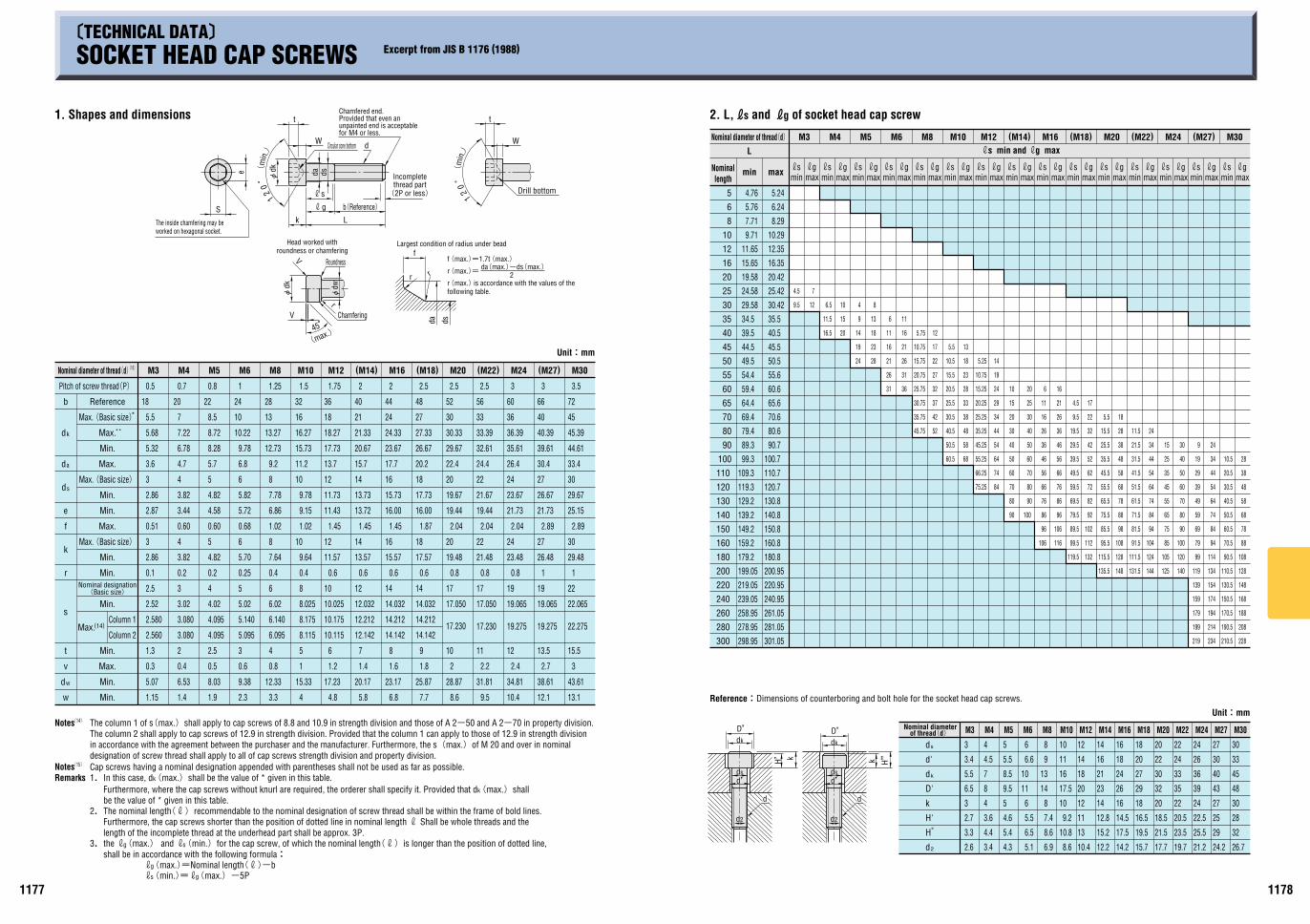
45B
r
V
f
r
da ds
r
W
t
12
0
B0
21
t
k
s
g
L
da ds
W d
13.1
43.61
3
15.5
22.275
22.065
22
1
29.48
30
2.89
25.15
29.67
30
33.4
44.61
45.39
45
72
3.5
12.1
38.61
2.7
13.5
19.275
19.065
19
1
26.48
27
2.89
21.73
26.67
27
30.4
39.61
40.39
40
66
3
10.4
34.81
2.4
12
19.275
19.065
19
0.8
23.48
24
2.04
21.73
23.67
24
26.4
35.61
36.39
36
60
3
9.5
31.81
2.2
11
17.230
17.050
17
0.8
21.48
22
2.04
19.44
21.67
22
24.4
32.61
33.39
33
56
2.5
8.6
28.87
2
10
17.230
17.050
17
0.8
19.48
20
2.04
19.44
19.67
20
22.4
29.67
30.33
30
52
2.5
7.7
25.87
1.8
9
14.142
14.212
14.032
14
0.6
17.57
18
1.87
16.00
17.73
18
20.2
26.67
27.33
27
48
2.5
6.8
23.17
1.6
8
14.142
14.212
14.032
14
0.6
15.57
16
1.45
16.00
15.73
16
17.7
23.67
24.33
24
44
2
5.8
20.17
1.4
7
12.142
12.212
12.032
12
0.6
13.57
14
1.45
13.72
13.73
14
15.7
20.67
21.33
21
40
2
4.8
17.23
1.2
6
10.115
10.175
10.025
10
0.6
11.57
12
1.45
11.43
11.73
12
13.7
17.73
18.27
18
36
1.75
4
15.33
1
5
8.115
8.175
8.025
8
0.4
9.64
10
1.02
9.15
9.78
10
11.2
15.73
16.27
16
32
1.5
3.3
12.33
0.8
4
6.095
6.140
6.02
6
0.4
7.64
8
1.02
6.86
7.78
8
9.2
12.73
13.27
13
28
1.25
2.3
9.38
0.6
3
5.095
5.140
5.02
5
0.25
5.70
6
0.68
5.72
5.82
6
1
6.8
9.78
10.22
10
24
1.9
8.03
0.5
2.5
4.095
4.095
4.02
4
0.2
4.82
5
0.60
4.58
4.82
5
5.7
8.28
8.72
8.5
22
0.8
1.4
6.53
0.4
2
3.080
3.080
3.02
3
0.2
3.82
4
0.60
3.44
3.82
4
4.7
6.78
7.22
7
20
0.7
1.15
5.07
0.3
1.3
2.560
2.580
2.52
2.5
0.1
2.86
3
0.51
2.87
2.86
3
3.6
5.32
5.68
5.5
18
0.5
w
s
a
k
w
d
v
t
s
r
k
f
e
d
d
d
b
M30(M27)M24(M22)M20(M18)M16(M14)M12M10M8M6M5M4M3
S
e
V
Fdk
Fdw
maxminmaxminmaxminmaxminmaxminmaxminmaxminmaxminmaxminmaxminmaxminmaxminmaxminmaxmin
26.7
32
28
30
48
45
33
30
24.2
29
25
27
43
40
30
27
21.2
25.5
22.5
24
39
36
26
24
19.7
23.5
20.5
22
35
33
24
22
17.7
21.5
18.5
20
32
30
22
20
15.7
19.5
16.5
18
29
27
20
18
14.2
17.5
14.5
16
26
24
18
16
12.2
15.2
12.8
14
23
21
16
14
10.4
13
11
12
20
18
14
12
8.6
10.8
9.2
10
17.5
16
11
10
8.6
7.4
8
14
13
9
8
6.5
5.5
6
11
10
6.6
6
4.3
5.4
4.6
5
9.5
8.5
5.5
5
3.4
4.4
3.6
4
8
7
4.5
4
2.6
3.3
2.7
3
6.5
5.5
3.4
3
2d
"H
H'
k
D'
kd
d'
sd
M30M27M24M22M20M18M16M14M12M10M8M6M5M4M3
228
208
188
168
148
128
108
88
78
68
58
48
38
28
210.5
190.5
170.5
150.5
130.5
110.5
90.5
70.5
60.5
50.5
40.5
30.5
20.5
10.5
234
214
194
174
154
134
114
94
84
74
64
54
44
34
24
219
199
179
159
139
119
99
79
69
59
49
39
29
19
9
140
120
100
90
80
70
60
50
40
30
125
105
85
75
65
55
45
35
25
15
144
124
104
94
84
74
64
54
44
34
24
131.5
111.5
91.5
81.5
71.5
61.5
51.5
41.5
31.5
21.5
11.5
148
128
108
98
88
78
68
58
48
38
28
18
135.5
115.5
95.5
85.5
75.5
65.5
55.5
45.5
35.5
25.5
15.5
5.5
132
112
102
92
82
72
62
52
42
32
22
17
119.5
99.5
89.5
79.5
69.5
59.5
49.5
39.5
29.5
19.5
9.5
4.5
116
106
96
86
76
66
56
46
36
26
21
16
106
96
86
76
66
56
46
36
26
16
11
6
100
90
80
70
60
50
40
30
25
20
90
80
70
60
50
40
30
20
15
10
84
74
64
54
44
34
29
24
19
14
75.25
66.25
55.25
45.25
35.25
25.25
20.25
15.25
10.75
5.25
68
58
48
38
33
28
23
18
13
60.5
50.5
40.5
30.5
25.5
20.5
15.5
10.5
5.5
52
42
37
32
27
22
17
12
45.75
35.75
30.75
25.75
20.75
15.75
10.75
5.75
36
31
26
21
16
11
31
26
21
16
11
6
28
23
18
13
8
24
19
14
9
4
20
15
10
16.5
11.5
6.512
7
9.5
4.5
301.05
281.05
261.05
240.95
220.95
200.95
180.8
160.8
150.8
140.8
130.8
120.7
110.7
100.7
90.7
80.6
70.6
65.6
60.6
55.6
50.5
45.5
40.5
35.5
30.42
25.42
20.42
16.35
12.35
10.29
8.29
6.24
5.24
298.95
278.95
258.95
239.05
219.05
199.05
179.2
159.2
149.2
139.2
129.2
119.3
109.3
99.3
89.3
79.4
69.4
64.4
59.4
54.4
49.5
44.5
39.5
34.5
29.58
24.58
19.58
15.65
11.65
9.71
7.71
5.76
4.76
300
280
260
240
220
200
180
160
150
140
130
120
110
100
90
80
70
65
60
55
50
45
40
35
30
25
20
16
12
10
8
6
5
s g s g s g s g s g s g s g s g s g s g s g s g s g s g gmaxmin
smaxmin
L
M3 M4 M5 M6 M8 M10 M12 (M14) M16 (M18) M20 (M22) M24 (M27) M30
5.1 6.9
Fdk
r
r
rrrr r rr r r r r r rrrr r rr r rrr r rr r rr r
H''k
d
d2
d'ds
D'dk
H'
dk
D'
k
dsd'
d2
d
11781177
B
SOCKET HEAD CAP SCREWS Excerpt from JIS B 1176 (1988)TECHNICAL DATA
1. Shapes and dimensions
The inside chamfering may be worked on hexagonal socket.
(m
in.)
Chamfered end.Provided that even an unpainted end is acceptable for M4 or less.
Circular cone bottom
(2P or less)
Incompletethread part
b(Reference)
Head worked withroundness or chamfering
Roundness
(max.)
Chamfering
Largest condition of radius under bead
Drill bottom
(m
in.)
f(max.)=1.7t(max.)
r(max.) is accordance with the values of the following table.
r(max.)= da(max.)-ds(max.)2
Unit:mm
Pitch of screw thread(P)
(15)Nominal diameter of thread(d)
**Max.
*Max.(Basic size)
Reference
Max.
Min.
Max.(Basic size)
Max.(Basic size)
Min.
Min.
Max.
Min.
Min.
Min.
Nominal designation(Basic size)
Column 2
Column 1(14)Max.
Max.
Min.
Min.
Min.
Remarks
(14)Notes
(15)Notes
3.the rg(max.) and rs(min.)for the cap screw, of which the nominal length(r)is longer than the position of dotted line, shall be in accordance with the following formula:
Furthermore, the cap screws shorter than the position of dotted line in nominal length r Shall be whole threads and the length of the incomplete thread at the underhead part shall be approx. 3P.
2.The nominal length(r)recommendable to the nominal designation of screw thread shall be within the frame of bold lines.
Furthermore, where the cap screws without knurl are required, the orderer shall specify it. Provided that dk(max.)shall be the value of * given in this table.
1.In this case, dk(max.)shall be the value of * given in this table.Cap screws having a nominal designation appended with parentheses shall not be used as far as possible.
The column 1 of s(max.)shall apply to cap screws of 8.8 and 10.9 in strength division and those of A 2-50 and A 2-70 in property division. The column 2 shall apply to cap screws of 12.9 in strength division. Provided that the column 1 can apply to those of 12.9 in strength division in accordance with the agreement between the purchaser and the manufacturer. Furthermore, the s(max.)of M 20 and over in nominal designation of screw thread shall apply to all of cap screws strength division and property division.
rg(max.)=Nominal length(r)-brs(min.)=rg(max.)-5P
Reference:Dimensions of counterboring and bolt hole for the socket head cap screws.
Nominal diameterof thread(d)
Unit:mm
Nominallength
Nominal diameter of thread(d)
2. L,Rs and Rg of socket head cap screw
s min and g maxr r
PD-9 2nd

1
Ú0.05
Ú0.1
Ú0.15
Ú0.2
Ú0.3
Ú0.5
Ú0.1
Ú0.2
Ú0.3
Ú0.5
Ú0.8
Ú1.2
Ú0.3
Ú0.5
Ú0.8
Ú1.2
Ú2
Ú3 Ú6Ú3Ú1.2
Ú4Ú2Ú0.8
Ú2.5Ú1.2Ú0.5
Ú1.5Ú0.8Ú0.3
Ú1Ú0.5Ú0.2
Ú0.5Ú0.3Ú0.1
t 1.6< 3< 6<
Ú0.1
Ú0.2
Ú0.3
Ú0.5
Ú0.8
Ú1.2
Ú0.3
Ú0.5
Ú0.8
Ú1
Ú1.5
Ú2
-
Ú0.3
Ú0.4
Ú0.5
Ú0.8
Ú1.2
-
Ú0.5
Ú0.8
Ú1.2
Ú2
Ú2.5
-
Ú0.8
Ú1
Ú1.5
Ú2
Ú3
-
Ú1.2
Ú1.5
Ú2
Ú3
Ú4
-
-
-
-
-
-
-
Ú1.5
Ú2
Ú2.5
Ú3
Ú4
6
4
3
2
1.5
-
-
-
-
-
-
-
5
3
2
1.5
0.8
-
3
2
1.5
0.8
0.5
-
2.5
1.5
1
0.5
0.3
-
1.2
0.8
0.5
0.3
0.2
-
2
1.2
0.8
0.5
0.3
0.2
1.2
0.8
0.5
0.3
0.2
0.1
t 3< 6<
-
0.3
0.8
1.5
3
6
-
0.5
1.2
3
6
10
-
0.5
1
2
4
6
-
0.8
1.5
3
6
10
-
-
-
-
-
-
-
1.5
2
3
6
10
Ú8
Ú4
Ú2
-Ú0.3
Ú0.8
Ú2
Ú4
Ú0.5
Ú1.2
Ú3
Ú6
Ú1.2
Ú2.5
Ú0.5
Ú0.2
Ú0.8
Ú1.5
Ú0.3
Ú0.15
Ú0.5
Ú1
Ú0.2
Ú0.5
Ú0.1
Ú0.3
Ú0.1
Ú0.05
-
Ú0.2
Ú0.1
Ú0.05
c
v
m
f
f
m
c
v
Ú0.2
Ú0.4 Ú1
Ú0.5 Ú1
Ú2
Ú1B
Ú1B30“
Ú3B
Ú 1B
Ú 2B
Ú30“ Ú20“
Ú30“
Ú 1B
Ú10“
Ú15“
Ú30“
Ú 5“
Ú10“
Ú20“v
c
m
f
H
K
L
L
K
H
0.2
0.4
0.6 1
0.6
0.3
1.5
0.8
0.4
2
1
0.5
0.02
0.05
0.1
0.05
0.1
0.2
0.1
0.2
0.4
0.2
0.4
0.8
0.3
0.6
1.2
0.4
0.8
1.6
¯1.6 t¯3 t¯6 t¯12
t¯1.6 1.6< t¯3 6< t¯123< t¯6
¯3 t¯6 t¯12
11761175
( )
Excerpt from JIS B 0408/0410(1991) Excerpt from JIS B 0405/0419(1991)GENERAL DIMENSIONAL TOLERANCEGENERAL DIMENSIONAL TOLERANCES FOR PARTS FORMED BY PRESS WORKING FROM SHEET METAL AND SHEAR FROM METAL PLATES
TECHNICAL DATA TECHNICAL DATA
Table 1. General dimensional tolerance of blanking Unit:mm
1. General dimensional tolerances for parts formed by press working from sheet metal
Basic size stepGrades
Grade A Grade B Grade C
Over 1000 to 2000 incl.
Over 400 to 1000 incl.
Over 120 to 400 incl.
Over 30 to 120 incl.
Over 6 to 30 incl.
6 or less
Note: Grade A, B and C are equal to tolerance grade f, m and c of JIS B 0405 respectively.
Unit:mmTable 2. adimensional tolerance of bending and drawing
Grade C Grade BGrade A
GradesBasic size step
Over 1000 to 2000 incl.
Over 400 to 1000 incl.
Over 120 to 400 incl.
Over 30 to 120 incl.
Over 6 to 30 incl.
6 or less
Grade A, B and C are equal to tolerance grade m, c and v of JIS B 0405 respectively.
Note:
2. General tolerances for parts formed by shear from metal plates
Table 1. General dimaensional tolerance of cut width Unit:mm
Unit:mmTable 2. General tolerance of straightness
Over 2000 to 4000 incl.
Over 1000 to 2000 incl.
Over 400 to 1000 incl.
Over 120 to 400 incl.
Over 30 to 120 incl.
30 or less
Over 2000 to 4000 incl.
Over 1000 to 2000 incl.
Over 400 to 1000 incl.
Over 120 to 400 incl.
Over 30 to 120 incl.
30 or less
Basic size step
Nominal length oncut dimension
Grade A Grade B Grade A Grade B Grade A Grade B Grade A Grade B
Board thickness(t)
Grades
Grades
Board thickness(t)
Grade B Grade AGrade B Grade AGrade BGrade AGrade BGrade A
Grade A Grade B Grade A Grade B Grade A Grade B
Board thickness(t)
Grades
Unit:mmTable 3. General tolerance of perpendicularity
Nominal length on shorter side
Over 2000 to 4000 incl.
Over 1000 to 2000 incl.
Over 400 to 1000 incl.
Over 120 to 400 incl.
Over 30 to 120 incl.
30 or less
1. General dimensional tolerance of cutting
Unit:mmLength dimensional tolerance (excluding chamfered parts)
3. Tolerance of angle dimension
Unit:mm
2. Length dimensional tolerance in chamfered parts (corner roundness or chamfer dimension)
Unit:mm
Degree Basic size step
Symbol Explanation
0.5 to
3 incl.
Over 30 to
120 incl.
Over 6 to
30 incl.
Over 3 to
6 incl.
Tolerance
Over 2000 to
4000 incl.
Over 1000 to
2000 incl.
Over 400 to
1000 incl.
Over 120 to
400 incl.
Coarse
Very coarse
Medium
Fine
1Note( ):Tolerance for standard dimensions of less than 0.5mm shall be specified individually.
Degree Basic size step
Symbol
Shorter side of cornerDegree
Symbol ExplanationExplanation
Fine
Medium
Coarse
Very coarse
Fine
Medium
Coarse
Very coarse
0.5 ( ) to
3 incl.
1 Over 3 to
6 incl.Over 6
Over 10 to
50 incl.
Over 50 to
120 incl.
Over 120 to
400 incl.10 or less
Note( ):Tolerance for standard dimensions of less
than 0.5mm shall be specified individually.
1
Over 400
4. General tolerance of perpendicularityUnit:mmJIS B 0419-1991
Over 300 to
1000 incl.
Over 100 to
300 incl.
Over 1000 to
3000 incl.100 or lessDegree
Nominal length on shorter side
Perpendicularity tolerance
Nominal area
Degree
5. General tolerance of straightness and flatnessUnit:mmJIS B 0419-1991
Over 30 to 100 incl.
10 or less Over 10 to 30 incl.
Over 100 to 300 incl.
Over 300 to 1000 incl.
Over 1000 to 3000 incl.
Straightness and flatness tolerance
JIS B 0408
JIS B 0410 -1991
-1991
ToleranceTolerance
-1991JIS B 0405
PD-8 1st

11741173
--
--
--
--
--
--
--
-
--
----77-
56-
67-
46-
56-
38-
51-
33-
43-
28-
36-
24-
30-
20
-16
6-
131
-14
6-
111
-12
1-
91-
106
-76-
86-
61-
76-
51-
61-
40-
54-
33
-44-
26
-37-
22-
31-
19-
28-
18
-17
1-
131
-15
9-
119
-14
7-
107
-12
6-
91-
113
-78-
94-
64-
85-
55-
70-
45-
64-
39-
54-
33
-----
-16
9-
123
-15
9-
113
-15
1-
105
-13
3-
93-
125
-85
-11
7-
77-
101
-66-
93-
58-
78-
48-
72-
42
-59-
34
-48-
27
-39-
21
-32-
17-
27-
15-
24-
14
-17
2-
109
-16
6-
103
-15
0-
93-
144
-87
-13
0-
78-
126
-74
-11
3-
67-
109
-63
-10
6-
60-
93-
53-
90-
50-
88-
48-
76-
41-
73-
38-
62-
32-
60-
30
-50-
25
-41-
20
-34-
16
-28-
13-
23-
11-
20-
10
-10
8-
45
-98-
41
-88-
36
-79-
33
-68-
28
-59-
24
-51-
21
-42-
17
-35-
14
-29-
11
-24-
9-
20-
8-
16-
6
-95-
55
-87-
51
-79-
47
-70-
41
-61-
36
-52-
30
-45-
26
-37-
21
-31-
18
-26-
15
-21-
12-
17-
9-
12-
6
-80-
17
-73-
16
-66-
14
-60-
14
-52-
12
-45-
10
-39-
9
-33-
8
-28-
7
-23-
5
-19-
4-
16-
4-
14-
4
-67-
27
-62-
26
-57-
25
-51-
22
-45-
20
-38-
16
-33-
14
-28-
12
-24-
11
-20-
9
-16-
7-
13-
5-
10-
4
-630
-570
-520
-460
-400
-350
-300
-250
-210
-180
-150-
120-
12-
2
-50-
10
-46-
10
-41-
9
-37-
8
-33-
8
-28-
6
-24-
5
-20-
4
-17-
4
-15-
4
-12-
3-
9-
1-
8-
2
-45+
18
-40+
17
-36+
16
-33+
13
-28+
12
-25+
10
-21+
9
-18+
7
-15+
6
-12+
6
-10+
5-
9+
3-
100
-32+
8
-29+
7
-27+
5
-24+
5
-21+
4
-18+
4
-15+
4
-13+
3
-11+
2
-9+
2
-7+
2-
6+
2-
60
Ú23
Ú20
Ú5
Ú6
Ú7
Ú9
Ú10
Ú12
Ú15
Ú17
Ú26
Ú28
Ú31
Ú20
Ú18
Ú16
Ú14
.5
Ú12
.5
Ú11Ú
9.5
Ú8
Ú6.
5
Ú5.
5
Ú4.
5
Ú4
Ú3
0+
2500
+23
00+
2100
+18
50+
1600
+14
00+
1200
+10
00+
840+
700+
580+
480+
40X7
U7T7
S7R7
P7P6
N7N6
M7
M6
K7K6
JS7
JS6
H10
H9
0+
1550
+14
00+
1300
+11
50+
1000
+870+
740+
620+
520+
430+
360+
300+
25
0+
970+
890+
810+
720+
630+
540+
460+
390+
330+
270+
220+
180+
14
0+
630+
570+
520+
460+
400+
350+
300+
250+
210+
180+
150+
120+
10
0+
400+
360+
320+
290+
250+
220+
190+
160+
130+
110+
90+
80+
6
+20
+83
+18
+75
+17
+69
+15
+61
+14
+54
+12
+47
+10
+40
+9
+34
+7
+28
+6
+24
+5
+20+
4+
16+
2+
12
+20
+60
+18
+54
+17
+49
+15
+44
+14
+39
+12
+34
+10
+29
+9
+25
+7
+20
+6
+17
+5
+14+
4+
12+
2+
8
+68
+16
5
+62
+15
1
+56
+13
7
+50
+12
2
+43
+10
6
+36
+90
+30
+76
+25
+64
+20
+53
+16
+43
+13
+35
+10
+28+
6+
20
+68
+13
1
+62
+11
9
+56
+10
8
+50
+96
+43
+83
+36
+71
+30
+60
+25
+50
+20
+41
+16
+34
+13
+28
+10
+22+
6+
16
+68
+10
8
+62
+98
+56
+88
+50
+79
+43
+68
+36
+58
+30
+49
+25
+41
+20
+33
+16
+27
+13
+22
+10
+18+
6+
12
+13
5+
290
+12
5+
265
+11
0+
240
+10
0+
215
+85
+18
5
+72
+15
9
+60
+13
4
+50
+11
2
+40
+92
+32
+75
+25
+61
+20
+50
+14
+39
+13
5+
232
+12
5+
214
+11
0+
191
+10
0+
172
+85
+14
8
+72
+12
6
+60
+10
6
+50
+89
+40
+73
+32
+59
+25
+47
+20
+38
+14
+28
+13
5+
198
+12
5+
182
+11
0+
162
+10
0+
146
+85
+12
5
+72
+10
7
+60
+90
+50
+75
+40
+61
+32
+50
+25
+40
+20
+32
+14
+24
+23
0+
480
+21
0+
440
+19
0+
400
+17
0+
355
+14
5+
305
+12
0+
260
+10
0+
220
+80
+18
0
+65
+14
9
+50
+12
0
+40
+98
+30
+78
+20
+60
+23
0+
385
+21
0+
350
+19
0+
320
+17
0+
285
+14
5+
245
+12
0+
207
+10
0+
174
+80
+14
2
+65
+11
7
+50
+93
+40
+76
+30
+60
+20
+45
+23
0+
327
+21
0+
299
+19
0+
271
+17
0+
242
+14
5+
208
+12
0+
174
+10
0+
146
+80
+11
9
+65
+98
+50
+77
+40
+62
+30
+48
+20
+34
+48
0+
730
+44
0+
690
+40
0+
630
+36
0+
590
+33
0+
540
+30
0+
510
+28
0+
465
+26
0+
445
+24
0+
425
+23
0+
390
+21
0+
370
+20
0+
360
+18
0+
320
+17
0+
310
+15
0+
270
+14
0+
260
+13
0+
230
+12
0+
220
+11
0+
194
+95
+16
5
+80
+13
8+
70+
118
+60
+10
0
+48
0+
635
+44
0+
595
+40
0+
540
+36
0+
500
+33
0+
460
+30
0+
430
+28
0+
395
+26
0+
375
+24
0+
355
+23
0+
330
+21
0+
310
+20
0+
300
+18
0+
267
+17
0+
257
+15
0+
224
+14
0+
214
+13
0+
192
+12
0+
182
+11
0+
162
+95
+13
8
+80
+11
6+
70+
100
+60
+85
+84
0+
1090
+76
0+
1010
+68
0+
910
+60
0+
830
+54
0+
750
+48
0+
690
+42
0+
605
+38
0+
565
+34
0+
525
+31
0+
470
+28
0+
440
+26
0+
420
+24
0+
380
+22
0+
360
+20
0+
320
+19
0+
310
+18
0+
280
+17
0+
270
+16
0+
244
+15
0+
220
+15
0+
208
+14
0+
188
+14
0+
180
500
450
400
355
315
280
250
225
200
180
160
140
120
10080655040302418141063
450
400
355
315
280
250
225
200
180
160
140
120
10080655040302418141063
-
H8H7
H6G7
G6F8
F7F6
E9E8
E7D1
0D9
D8C1
0C9
B10
( mm
)
--
--
--
---
--
-
--
-
--
---
-----
Ú31
Ú28
Ú26
Ú23
Ú20
Ú17
Ú15
Ú12
Ú10
Ú9
Ú7
Ú6
Ú5
Ú3
Ú4
Ú4.
5
Ú5.
5
Ú6.
5
Ú8
Ú9.
5
Ú11
Ú12
.5
Ú14
.5
Ú16
Ú18
Ú20
Ú13
.5
Ú12
.5
Ú11
.5
Ú10Ú
9
Ú7.
5
Ú6.
5
Ú5.
5
Ú4.
5
Ú4
Ú3
Ú2.
5
Ú2
+64
+77
+54
+67
+45
+56
+40
+51
+34
+43
+28
+36
+20
+26
+14
4+
166
+12
4+
146
+10
2+
121
+87
+10
6+
70+
86+
60+
76+
48+
61+
41+
54
+33
+44
+28
+37
+23
+31
+18
+24
+14
6+
171
+13
4+
159
+12
2+
147
+10
4+
126
+91
+11
3+
75+
94+
66+
85+
54+
70+
48+
64+
41+
54
+14
0+
169
+13
0+
159
+12
2+
151
+10
8+
133
+10
0+
125
+92
+11
7+
79+
101
+71
+93
+59
+78
+53
+72
+43
+59
+35
+48
+28
+39
+23
+32
+19
+27
+14
+20
+13
2+
172
+12
6+
166
+11
4+
150
+10
8+
144
+98
+13
0+
94+
126
+84
+11
3+
80+
109
+77
+10
6+
68+
93+
65+
90+
63+
88+
54+
76+
51+
73+
43+
62+
41+
60
+34
+50
+28
+41
+23
+34
+19
+28
+15
+23
+10
+16
+68
+10
8
+62+
98
+56+
88
+50+
79
+43+
68
+37
+59
+32
+51
+26
+42
+22
+35
+18
+29
+15
+24
+12
+20+
6+
12
+40+
80
+37+
73
+34+
66
+31+
60
+27+
52
+23
+45
+20
+39
+17
+33
+15
+28
+12
+23
+10
+19+
8+
16+
4+
10
+23+
63
+21+
57
+20+
52
+17+
46
+15+
40
+13
+35
+11
+30
+9
+25
+8
+21
+7
+18
+6
+15+
4+
12+
2+
8
+23+
50
+21+
46
+20+
43
+17+
37
+15+
33
+13
+28
+11
+24
+9
+20
+8
+17
+7
+15
+6
+12+
4+
9+
2+
6
+5
+45
+4
+40
+4
+36
+4
+33
+3
+28+
3+
25
+2
+21
+2
+18
+2
+15
+1
+12
+1
+10+
1+
90+
6
+5
+32
+4
+29
+4
+27
+4
+24
+3
+21+
3+
18
+2
+15
+2
+13
+2
+11
+1
+9
+1
+7
+1
+60
+4
-15
50
-14
00
-13
00
-11
50
-10
00
-870
-740
-620
-520
-430
-360
-300
-250
-970
-890
-810
-720
-630
-540
-460
-390
-330
-270
-220
-180
-140
-630
-570
-520
-460
-400
-350
-300
-250
-210
-180
-150
-120
-100
-400
-360
-320
-290
-250
-220
-190
-160
-130
-110
-90
-80
-60
-270
-250
-230
-200
-180
-150
-130
-110
-90
-80
-60
-50
-40
-60
-20
-54
-18
-49
-17
-44
-15
-39
-14
-34
-12
-29
-10
-25-
9
-20-
7
-17-
6
-14-
5-
12-
4-
8-
2
-47
-20
-43
-18
-40
-17
-35
-15
-32
-14
-27
-12
-23
-10
-20-
9
-16-
7
-14-
6
-11-
5-
9-
4-
6-
2
-16
5-
68
-15
1-
62
-13
7-
56
-12
2-
50
-10
6-
43
-90
-36
-76
-30
-64
-25
-53
-20
-43
-16
-35
-13
-28
-10
-20-
6
-13
1-
68
-11
9-
62
-10
8-
56
-96
-50
-83
-43
-71
-36
-60
-30
-50
-25
-41
-20
-34
-16
-28
-13
-22
-10
-16-
6
-10
8-
68
-98
-62
-88
-56
-79
-50
-68
-43
-58
-36
-49
-30
-41
-25
-33
-20
-27
-16
-22
-13
-18
-10
-12-
6
-29
0-
135
-26
5-
125
-24
0-
110
-21
5-
100
-18
5-
85
-15
9-
72
-13
4-
60
-11
2-
50
-92
-40
-75
-32
-61
-25
-50
-20
-39
-14
-23
2-
135
-21
4-
125
-19
1-
110
-17
2-
100
-14
8-
85
-12
6-
72
-10
6-
60
-89
-50
-73
-40
-59
-32
-47
-25
-38
-20
-28
-14
-19
8-
135
-18
2-
125
-16
2-
110
-14
6-
100
-12
5-
85
-10
7-
72
-90
-60
-75
-50
-61
-40
-50
-32
-40
-25
-32
-20
-24
-14
-38
5-
230
-35
0-
210
-32
0-
190
-28
5-
170
-24
5-
145
-20
7-
120
-17
4-
100
-14
2-
80
-11
7-
65
-93
-50
-76
-40
-60
-30
-45
-20
-32
7-
230
-29
9-
210
-27
1-
190
-24
2-
170
-20
8-
145
-17
4-
120
-14
6-
100
-11
9-
80
-98
-65
-77
-50
-62
-40
-48
-30
-34
-20
-63
5-
480
-59
5-
440
-54
0-
400
-50
0-
360
-46
0-
330
-43
0-
300
-39
5-
280
-37
5-
260
-35
5-
240
-33
0-
230
-31
0-
210
-30
0-
200
-26
7-
180
-25
7-
170
-22
4-
150
-21
4-
140
-19
2-
130
-18
2-
120
-16
2-
110
-13
8-
95
-11
6-
80-
100
-70
-85
-60
-99
5-
840
-91
5-
760
-82
0-
680
-74
0-
600
-67
0-
540
-61
0-
480
-53
5-
420
-49
5-
380
-45
5-
340
-41
0-
310
-38
0-
280
-36
0-
260
-32
7-
240
-30
7-
220
-27
4-
200
-26
4-
190
-24
2-
180
-23
2-
170
-21
2-
160
-19
3-
150
-18
6-
150
-17
0-
140
-16
5-
140
x6u
6t6
s6r6
p6
n6
m6
m5
k6k5
js7
js6
js5
h9
h8
h7
h6
h5
g6
g5
f8f7
f6e9
e8
e7
d9
d8
c9b9
500
450
400
355
315
280
250
225
200
180
160
140
120
10080655040302418141063
450
400
355
315
280
250
225
200
180
160
140
120
10080655040302418141063
-
( mm)
+20
+4
n5 +
8
+16+
8+
13
+10
+12
+38
+17
+28
+20
+33
+23
- - - - -
*h4*
+24
+15
-200
-180
-160
-140
-120
-100
-80
-70
-60
-50
-40
-40
-30
TOLERANCES OF COMMONLY USED HOLE FITS Excerpt fromJIS B 0401(1986) TOLERANCES OF COMMONLY USED SHAFT FITS Excerpt from
JIS B 0401(1986)
TECHNICAL DATA TECHNICAL DATADe
viat
ions
of h
oles
to b
e us
ed in
com
mon
ly u
sed
fits
Basi
csi
ze s
tep
Devi
atio
ns o
f sha
fts to
be
used
in c
omm
only
use
d fit
sBa
sic
size
ste
p
or less
Over
or les
sOv
er
Note:
This
tabl
e sh
ows
that
the
uppe
r fig
ures
are
the
uppe
r dev
iatio
n an
d th
e lo
wer
figu
res
are
the
low
er d
evia
tion.
Note:
This
tabl
e sh
ows
that
the
uppe
r fig
ures
are
the
uppe
r dev
iatio
n an
d th
e lo
wer
figu
res
are
the
low
er d
evia
tion.
Tole
ranc
e zo
ne c
lass
of h
ole
Tole
ranc
e zo
ne c
lass
of s
haft
Unit:O
m
Unit:O
m
PD-7 1st

H8H7
F8F7
E7
11721171
H6
h8h7
n6n5h6h5
h9
x6u6t6s6r6p6n6m6k6js6h6
r5p5m5k5js5h5
f8f7
c9 e9d9
e8d9
g6f7e7
g5f6
H9H8
H7
h9h8
h7h6
h6h5
h6h5
H10
H9H8
H7H6
H9H8
E9E8
D10
D9D8
C10
C9B1
0H9
H8F8
E9E8
D9D8
X7U7
T7S7
R7P7
P6K7
N7N6
M7M6
K6JS7
JS6G7
H7H6
G6F7
F6P6
N6M6
K5JS6
M6
h9h8
h7
200
150
100 50 0
-50
d9c9
b9d8
h9h8
e9g8
d9c9
h8h7
f8f7
e9e8
d9x6
u6t6
s6r6
p6n6
m6k6
js7js6
h7h6
g6f7
f6e7
p6n6
m6m5
k6k5
js6js5
h6h5
g6g5
f6
-20
0
-15
0
-10
0
-50050
H10
H9H8
H7H6
h9h8h7h6h5
X7U7
T7S7
R7
P6
B10
C9 C10
D8 D9 D10
D8D9
E9E8E9E8E7
F8F8F7F7F6G6 G7
H9H6 H6 H7 H7 H8 H9H8H8
JS6
JS6
JS7
K6 K6 K7
M6
M6
M7
x6u6
t6s6
n6m
6m
6m
5
k6k6k5
js7
js6
js6
js5
h8 h8 h9h7h7h6h6h5
g6g6g5f6 f6 f7 f7 f8
e7 e8 e9 e8 e9
d9 d8 d9d9c9c9
b9H1
0
H9H8H7H6p6*
n6*
r6*
P7*
P6*
N6 N7N6*
p6*
Excerpt from JIS B 0401(1986) BASIS OF SELECTION FOR FITS SYSTEM OF LIMITS AND FITSExcerpt from "Usage of JIS series" Manual for Designing (Precision Ver.)
TECHNICAL DATA TECHNICAL DATAFu
nctio
nal c
lass
ifica
tion
Appl
icat
ion
exam
ple
Appl
icab
le p
art
Can be moved relatively
Clearance fitPrecisionrolling fitRolling fitLight rolling fitLoose fit
Cannot be moved relatively
Transition fit
Light press fitDriving fitPush fitLubricated fit
Interference fit
Press fitStrong press fitC
Shrinkage fitCCooling fit
The
part
which
allo
ws a
larg
e cle
aran
ce s
pace
or t
he p
art r
equi
res
clear
ance
spa
ce.
The
part
which
can
be
enlar
ged
to m
ake
clear
ance
spa
ce to
mak
e as
sem
bly
easie
r. Th
e pa
rt wh
ich re
quire
s pr
oper
clea
ranc
e sp
ace
in th
e hi
gh te
mpe
ratu
re.
The
part
whi
ch a
llow
s a
larg
e cl
eara
nce
spac
e or
the
part
requ
ires
clea
ranc
e sp
ace.
Func
tiona
lly, th
e part
whic
h req
uires
larg
e clea
rance
spac
e
For r
educ
ing
Safe
ty c
ost
Prod
uctio
n co
st
Leng
th o
f fit
is lo
ng.
Expa
nse.
Pos
ition
ing
erro
r is
larg
e.
The
gene
ral r
otat
ing
or tr
aveli
ng p
art.
(Th
e co
nditi
on o
f goo
d lu
brica
tion
is re
quire
d.)
Ordi
nary
fit p
arts
.(
Disa
ssem
blin
g is
ofte
n do
ne.)
The
part
whi
ch re
quire
s pr
ecis
ion
mov
emen
t with
out a
ny s
lack
.
The
part
whi
ch
requ
ires
prec
isio
n m
ovem
ent w
ithou
t an
y sl
ack.
Tran
smis
sion
of
pow
er c
an n
ot b
e do
ne b
y on
ly
junc
tion
pow
er o
f fit.
Small
pow
er c
an b
e tra
nsm
itted
by
junc
tion
powe
r of f
it.
Hard
to d
isas
sem
ble
with
out d
amag
ing
com
pone
nts.
Cons
ider
able
pow
er
can
be tr
ansm
itted
by
junc
tion
pow
er o
f fit.
Pres
s di
e pa
rts a
re s
how
n in
the
appl
icat
ion
exam
ple
for t
he it
em w
ritte
n in
red
lette
rs.
Fixa
tion
of b
ushi
ng fo
r bea
ring
Fixa
tion
of d
rivin
g ge
ar a
nd b
oss
Fixa
tion
of jo
int f
lang
e an
d sh
aft( l
arge
torq
ue)
Insert
ion of
valve
seat
for in
let va
lve
Dowe
l pin
MST(
p6)
Fixa
tion
of b
ushi
ng fo
r bea
ring
Join
t and
sha
ft
Ream
er b
olt
Fixa
tion
of g
ear p
ump
shaf
t and
cas
ing
Fit o
f rim
of t
ooth
ed g
ear a
nd b
oss
Gove
rnor
way
and
pin
Fit b
etw
een
join
t fla
nges
Pin
for l
ink
syst
em a
nd le
ver
Key
and
key
groo
veVa
lve
stem
of p
reci
sion
con
trol v
alve
Fit o
f loo
seni
ng s
afet
y pi
n
Pist
on ri
ng a
nd p
isto
n rin
g gr
oove
Cran
k web
and p
in be
aring(
Side
surfa
ce)
Exha
ust v
alve c
age a
nd tr
aveli
ng pa
rt of
sprin
g she
etPi
ston r
ing an
d pist
on ri
ng gr
oove
Fit o
f exh
aust
valv
e se
atM
ain b
earin
g fo
r cra
nksh
aft
Gene
ral t
rave
ling
part
Stri
pper
bol
t MSB(
e9)
Inse
rtion
par
t of c
oolin
g ex
haus
t valv
e ca
geGe
nera
l sha
ft an
d bu
shin
g G
uide
lifte
r pin(
g6)
Leve
r for
ling
sys
tem
and
bus
hing
Fit o
f too
thed
gea
r of p
recis
ion
gear
mec
hani
sm
Fit o
f rim
and
bos
s Do
wel
pin
MST
H(h7)
Fit o
f joi
nt fl
ange
and
sha
ftFix
atio
n of
pist
on o
f hyd
raul
ic sy
stem
and
sha
ftRe
amer
bol
t Do
wel
pin
MST
M(m
6)
Flex
ible
pla
te c
oupl
ing
and
gear
( act
ive
side
)Fi
xatio
n of
gea
r and
sha
ft(sm
all t
orqu
e)Ins
ertion
of va
lve gu
ide fo
r inlet
valve
Straig
ht die
MSD
, etc.(
n5)
Insert
ion of
valve
guide
for in
let va
lve
Die M
HD, e
tc.(m5)
Prec
isio
n fit
Punc
h SP
AS, e
tc.(
m5)
Flex
ible
pla
te c
oupl
ing
and
gear
( pas
sive
sid
e)
The
part
which
allo
ws a
slig
ht c
leara
nce
spac
e or
the
part
requ
ires
clear
ance
sp
ace(
high
gra
de fi
t). T
he b
earin
g pa
rt wh
ich h
as s
light
clea
ranc
e sp
ace
and
good
lubr
icatio
n. T
he b
earin
g pa
rt wh
ich is
wor
king
unde
r the
con
ditio
n of
hig
h te
mpe
ratu
re, h
igh
spee
d an
d hi
gh lo
ad(
high
gra
de p
ress
ure
feed
lubr
icatio
n).
1.1
Com
mon
ly u
sed
hole
-bas
is fi
ts
Clea
ranc
e fit
Basi
c ho
leTr
ansi
tion
fitTo
lera
nce
zone
cla
ss o
f sha
ftIn
terfe
renc
e fit
1.2
Mut
ual r
elat
ions
of t
oler
ance
zon
e in
com
mon
ly u
sed
hole
-bas
is s
yste
m o
f fits
2.1
Com
mon
ly u
sed
shaf
t-bas
is fi
ts
2.2
Mut
ual r
elat
ions
of t
oler
ance
zon
e in
com
mon
ly u
sed
shaf
t-bas
is s
yste
m o
f fits
Basic
shaf
tTo
lera
nce
zone
cla
ss o
f hol
eCl
eara
nce
fitTr
ansi
tion
fitIn
terfe
renc
e fit
Fit w
hich
can
be
mob
ile d
ue to
pro
per c
lear
ance
spa
ce(hi
gh g
rade
fit)
.Th
e ge
nera
l col
d be
arin
g pa
rt of
gre
ase
or o
il lu
bric
atio
n.
The c
ontin
uous
rotar
y par
t of li
ght lo
ad pr
ecisi
on m
achin
e.Fit
whic
h can
be m
obile
in sp
ite of
small
clea
ranc
e spa
ce(sp
igot a
nd po
sition
ing)
.Pr
ecisi
on tr
aveli
ng pa
rt.
Fit w
hich c
an be
mov
ed m
anua
lly w
ith us
ing a
lubric
ator(
high g
rade
posit
ioning).
Spec
ial pr
ecisi
on tr
aveli
ng pa
rt.St
ation
ary p
art w
hich i
s not
of gr
eat im
porta
nce.
Mou
ntin
g pa
rt wh
ich is
give
n a
little
leew
ay.
High
-pre
cisio
n po
sitio
ning
whe
re b
oth
are
imm
ovab
le.Fit
whi
ch c
an b
e as
sem
bled
and
disa
ssem
bled
by
wood
or l
ead
ham
mer
.
Fit w
hich c
an be
asse
mble
d and
disa
ssem
bled b
y an i
ron h
amm
er or
hand
pres
s(Ke
y or s
uch
item
s are
requ
ired t
o pre
vent
othe
r com
pone
nts f
rom
rotat
ing).
High
-pre
cision
posit
ioning
.
Sam
e as
the
abov
e fo
r ass
embl
ing
and
disa
ssem
blin
g.Hi
gh-p
recis
ion
posit
ioni
ng w
hich
doe
s no
t tol
erat
e an
y cle
aran
ce s
pace
.
Fit w
hich
requ
ires
cons
ider
able
powe
r for
ass
embl
ing
and
disa
ssem
blin
g.Hi
gh-p
recis
ion
fixed
mou
ntin
g.(
Key
or s
uch
item
s ar
e re
quire
d fo
r lar
ge to
rque
tra
nsm
issio
n.)
Fit wh
ich re
quire
s much
powe
r for a
ssemb
ling an
d disa
ssemb
ling.(
Key o
r such
items
are r
equire
d for
large
torqu
e tra
nsmiss
ion.)
Howe
ver, w
hen no
n-ferr
ous c
ompo
nents
are fit
ted to
gether
, pres
s fit p
ower
will b
e activ
ated.
Stand
ard pr
ess fit
fixing
betwe
en iro
n and
iron o
r betw
een br
onze
and co
pper.
Sam
e as t
he ab
ove f
or as
sem
bling
and
disas
sem
bling
.Sh
rinka
ge fi
t, co
oling
fit a
nd st
rong
pre
ss fi
t for
larg
e dim
ensio
n co
mpo
nent
s.
Fixe
d fir
mly
toge
ther
, so
that
per
man
ent a
ssem
blin
g ca
n be
sou
ght w
ith
shrin
kage
fit,
cool
ing
fit a
nd s
trong
pre
ss fi
t for
ass
embl
ing.
Pre
ss fi
t for
lig
ht a
lloy.
Notic
e(*)
Fits
will
mak
e ex
cept
ions
acc
ordi
ng to
the
size
ste
ps.
Basi
c ho
le
Fit
Clearance fit
Transition fit
Interference fit
Clea
ranc
e fit Lubricated fit
Trans
ition f
itInt
erfere
nce f
it
Driving fit
Press fit
Strong press fit
Shrinkage fit
Clea
ranc
e fit
Toler
ance z
one c
lass o
f shaf
t
(Om) Variation of tolerance
(Om) Variation of tolerance
Loose rolling fitLight rolling fit
Rolling fit
Clearance fit
Clearance fit
Notic
e(*)
Fits
will
mak
e ex
cept
ions
acc
ordi
ng to
the
size
ste
ps.
*Th
is ta
ble
show
s th
e ca
se w
hen
basi
c si
ze is
ove
r 18m
m to
30m
m.
*Th
is ta
ble
show
s th
e ca
se w
hen
basi
c si
ze is
ove
r 18m
m to
30m
m.
Basic
shaft
Fit
Clearance fit
Transition fit
Interference fit
Clearance fit
Tolera
nce zo
ne clas
s of sh
aft
Transition fit
Interference fit
Clearance fit
Clearance fit
Clearance fit
PD-6 1st
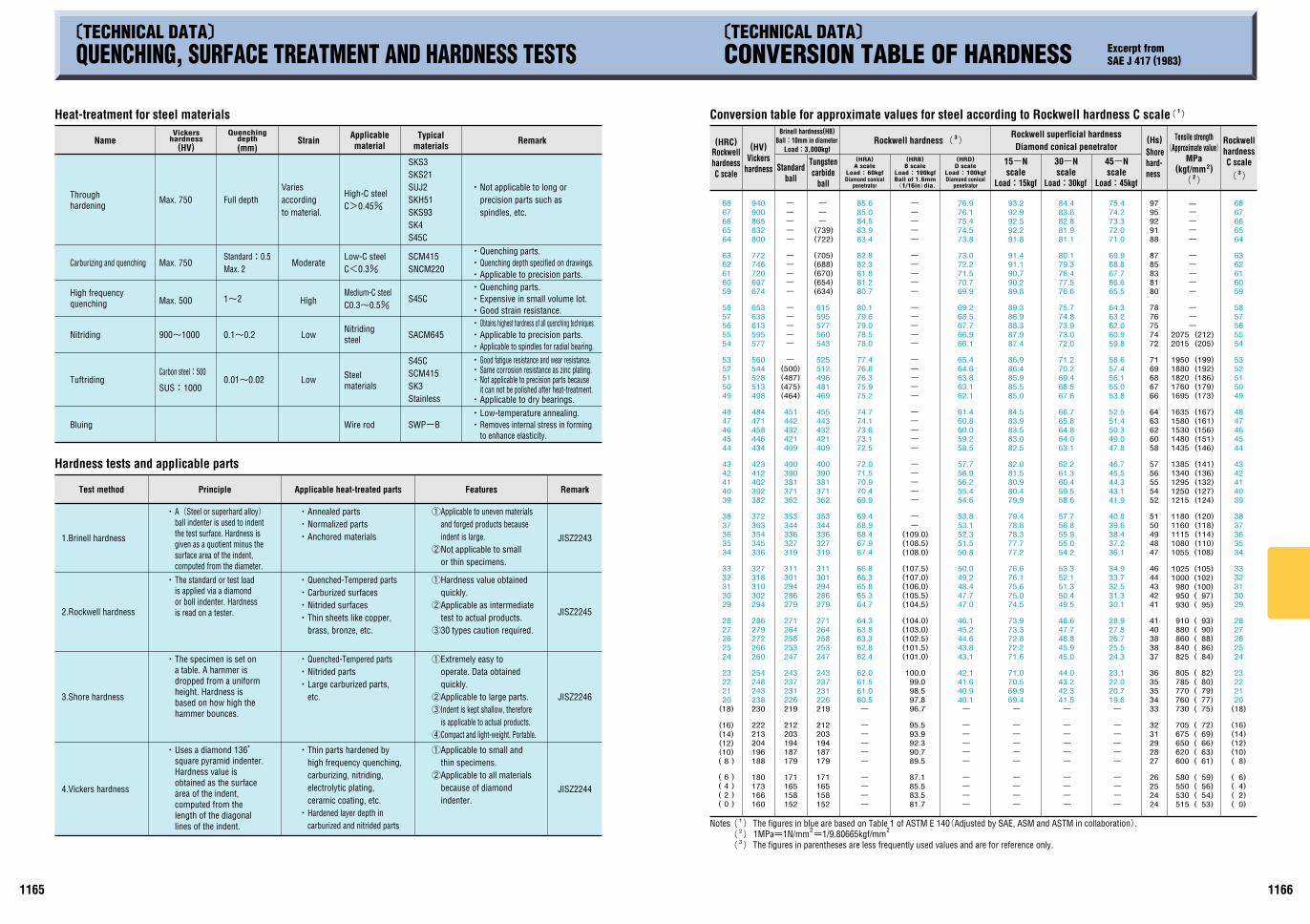
11661165
900~1000
C>0.45%
C<0.3%
C0.3~0.5%
SWP-B
SACM645
S45C
SNCM220SCM415
SKS21SUJ2SKH51SKS93SK4S45C
SKS3
SCM415SK3
S45C
1~2
0.1~0.2
0.01~0.02
JISZ2243
JISZ2245
JISZ2246
JISZ2244( 0)( 2)( 4)( 6)
( 8)(10)(12)(14)(16)
(18)20212223
2425262728
2930313233
3435363738
3940414243
4445464748
4950515253
5455565758
5960616263
6465666768
24242526
2728293132
3334353536
3738384041
4142434446
4748495051
5254555657
5860626364
6667686971
7274757678
8081838587
8891929597
152158165171
179187194203212
219226231237243
247253258264271
279286294301311
319327336344353
362371381390400
409421432443455
469481496512525
543560577595615
(634)(654)(670)(688)(705)
(722)(739)-
-
-
160166173180
188196204213222
230238243248254
260266272279286
294302310318327
336345354363372
382392402412423
434446458471484
498513528544560
577595613633653
674697720746772
800832865900940
( 0 )( 2 )( 4 )( 6 )
( 8 )(10)(12)(14)(16)
(18)20212223
2425262728
2930313233
3435363738
3940414243
4445464748
4950515253
5455565758
5960616263
6465666768
-
-
-
-
-
-
-
-
-
-
19.620.722.023.1
24.325.526.727.828.9
30.131.332.533.734.9
36.137.238.439.640.8
41.943.144.345.546.7
47.849.050.351.452.5
53.855.056.157.458.6
59.860.962.063.264.3
65.566.667.768.869.9
71.072.073.374.275.4
-
41.542.343.244.0
45.045.946.847.748.6
49.550.451.352.153.3
54.255.055.956.857.7
58.659.560.461.362.2
63.164.064.865.866.7
67.668.569.470.271.2
72.073.073.974.875.7
76.677.578.479.380.1
81.181.982.883.684.4
-
-
-
-
-
-
-
-
-
-
69.469.970.571.0
71.672.272.873.373.9
74.575.075.676.176.6
77.277.778.378.879.4
79.980.480.981.582.0
82.583.083.583.984.5
85.085.585.986.486.9
87.487.988.388.989.3
89.890.290.791.191.4
91.892.292.592.993.2
-
-
-
-
-
-
-
-
-
-
40.140.941.642.1
43.143.844.645.246.1
47.047.748.449.250.0
50.851.552.353.153.8
54.655.456.256.957.7
58.559.260.060.861.4
62.163.163.864.665.4
66.166.967.768.569.2
69.970.771.572.273.0
73.874.575.476.176.9
-
-
-
-
-
-
-
-
-
-
60.561.061.562.0
62.462.863.363.864.3
64.765.365.866.366.8
67.467.968.468.969.4
69.970.470.971.572.0
72.573.173.674.174.7
75.275.976.376.877.4
78.078.579.079.680.1
80.781.281.882.382.8
83.483.984.585.085.6
-
-
-
-
-
-
-
-
-152158165171
179187194203212
219226231237243
247253258264271
279286294301311
319327336344353
362371381390400
409421432442451
(464)(475)(487)(500)-
-
-
-
-
-
-
-
-
-
-
-
-
-
-
-
81.783.585.587.1
89.590.792.393.995.5
96.797.898.599.0
100.0
(101.0)(101.5)(102.5)(103.0)(104.0)
(104.5)(105.5)(106.0)(107.0)(107.5)
(108.0)(108.5)(109.0)-
-
-
-
-
-
-
-
-
-
-
-
-
-
-
-
-
-
-
-
-
-
-
-
-
-
-
-
-
-
-
-
515530550580
600620650675705
730760770785805
825840860880910
930950980
10001025
10551080111511601180
12151250129513401385
14351480153015801635
16951760182018801950
20152075-
-
-
-
-
-
-
-
-
-
-
--
(212)(205)
(199)(192)(186)(179)(173)
(167)(161)(156)(151)(146)
(141)(136)(132)(127)(124)
(105)(102)(100)( 97)( 95)
(120)(118)(114)(110)(108)
( 93)( 90)( 88)( 86)( 84)
( 82)( 80)( 79)( 77)( 75)
( 72)( 69)( 66)( 63)( 61)
( 59)( 56)( 54)( 53)
QUENCHING, SURFACE TREATMENT AND HARDNESS TESTS CONVERSION TABLE OF HARDNESS Excerpt fromSAE J 417 (1983)
Heat-treatment for steel materials
Name Strain Applicablematerial
Typicalmaterials Remark
Moderate
High
Low
Vickershardness
(HV)
Quenchingdepth(mm)
High frequencyquenching
Throughhardening
Carburizing and quenching
Nitriding
Tuftriding
Bluing
Max. 750
Max. 750
Max. 500
Carbon steel:500
SUS:1000
Full depth
Nitridingsteel
Steelmaterials
Wire rod
Variesaccordingto material.
High-C steel
Low-C steel
Medium-C steel
Low
Stainless
CNot applicable to long or precision parts such as spindles, etc.
CGood strain resistance.CExpensive in small volume lot.CQuenching parts.
CApplicable to spindles for radial bearing.CApplicable to precision parts.CObtains highest hardness of all quenching techniques.
CGood fatigue resistance and wear resistance.CSame corrosion resistance as zinc plating.CNot applicable to precision parts becauseait can not be polished after heat-treatment.CApplicable to dry bearings.CLow-temperature annealing.CRemoves internal stress in forming to enhance elasticity.
Standard:0.5Max. 2
Hardness tests and applicable parts
Test method Principle Features Remark
1.Brinell hardness
2.Rockwell hardness
3.Shore hardness
4.Vickers hardness
CA(Steel or superhard alloy) ball indenter is used to indent the test surface. Hardness is given as a quotient minus the surface area of the indent, computed from the diameter.CThe standard or test load is applied via a diamond or boll indenter. Hardness is read on a tester.
CThe specimen is set on a table. A hammer is dropped from a uniform height. Hardness is based on how high the hammer bounces.
CUses a diamond 136B square pyramid indenter. Hardness value is obtained as the surface area of the indent, computed from the length of the diagonal lines of the indent.
CAnchored materialsCNormalized partsCAnnealed parts
CThin sheets like copper, brass, bronze, etc.
CNitrided surfacesCCarburized surfacesCQuenched-Tempered parts
CLarge carburized parts, etc.
CNitrided partsCQuenched-Tempered parts
CHardened layer depth in carburized and nitrided parts
CThin parts hardened by high frequency quenching, carburizing, nitriding, electrolytic plating, ceramic coating, etc.
2Not applicable to small or thin specimens.
1Applicable to uneven materials and forged products because indent is large.
330 types caution required.
2Applicable as intermediate test to actual products.
1Hardness value obtained quickly.
2Applicable to all materials because of diamond indenter.
1Applicable to small and thin specimens.
3Indent is kept shallow, therefore is applicable to actual products.
2Applicable to large parts.
1Extremely easy to operate. Data obtained quickly.
4Compact and light-weight. Portable.
Applicable heat-treated parts
Conversion table for approximate values for steel according to Rockwell hardness C scale
(HRC)RockwellhardnessC scale
(HV)Vickers
hardness
Brinell hardness(HB)Ball:10mm in diameter
Load:3,000kgf
Standardball
Tungstencarbide
ball
(HRA)A scale
Load:60kgfDiamond conical
penetratorBall of 1.6mm(1/16in)dia.
Load:100kgfB scale(HRB) (HRD)
D scaleLoad:100kgfDiamond conical
penetrator
Rockwell superficial hardnessDiamond conical penetrator
15-Nscale
Load:15kgf Load:30kgfscale30-N
Load:45kgfscale45-N
(Hs)
The figures in blue are based on Table 1 of ASTM E 140(Adjusted by SAE, ASM and ASTM in collaboration).Notes
The figures in parentheses are less frequently used values and are for reference only.1MPa=1N/mm =1/9.80665kgf/mm2 2
(1)
(2)
(3)
CQuenching parts.
CApplicable to precision parts.CQuenching depth specified on drawings.
(1)
Rockwell hardness( 3) Rockwell
hardnessC scale(
3)
Tensile strength(Approximate value)
MPa
(2)
(kgf/mm )2
Shorehard-ness
TECHNICAL DATA TECHNICAL DATA
PD-3 1st
![[Technical Paper] Surface Modification of Polyethylene ...](https://static.fdocuments.net/doc/165x107/6185352dc0a3737cd12700eb/technical-paper-surface-modication-of-polyethylene-.jpg)


![EA763AD-54A...(JEMI 426)] (JEM1426)J 3 ELISA ) ELISA ) ELISA ) ELISA ELISA ) ELISA ) JIS Ll 902 JIS Z291 1 JIS Z2801 JIS Z2801 JIS Z2801 JIS Z2801 JIS Z2801 JIS 2911 JIS Z2801 JIS](https://static.fdocuments.net/doc/165x107/5e93b98e09aa5216734c1831/ea763ad-54a-jemi-426-jem1426j-3-elisa-elisa-elisa-elisa-elisa-elisa.jpg)