
Technical Data Sheet Extrusion Blow Moulding of … Data Sheet Extrusion Blow Moulding of Grilamid...
21
Technical Data Sheet Extrusion Blow Moulding of Grilamid and Grilon EMS-GRIVORY
Transcript of Technical Data Sheet Extrusion Blow Moulding of … Data Sheet Extrusion Blow Moulding of Grilamid...
Technical Data Sheet
Extrusion Blow Mouldingof Grilamid and Grilon
EMS-GRIVORY
3
1. EMS-GRIVORY extrusion blow mouldingmaterials
2. Processing behaviour of polyamide inextrusion blow moulding
2.1 Melt strength2.2 Drying2.3 Processing temperatures2.4 Parison swelling2.5 Blow-up ratio2.6 Shrinkage2.7 Recycling
3. Machinery for polyamide blow moulding
3.1 Extrusion blow moulding technologies for technicalparts
3.2 Extrusion blow moulding heads3.3 Screw configurations3.4 Tooling
4. Integration of joined parts
5. Processing problems and trouble shooting
5.1 Parison failures5.2 Part failures5.3 General mistakes
Contents
The data and recommendations given are based on ourexperience to date, however, no liability can be assumed inconnection with their usage and processing.
Domat/Ems, June 1998
4
The blow moulding process has been employed since about1950, though its application to polyamides came much later.In recent years the development of technical blow mouldingmaterials has been pushed ahead, so that there are now aconsiderable variety of them.
With Polyamide 6 there are now types ranging from good tovery high impact strength. The reinforced types are being pro-duced with 15 % and 20 % glass fibre reinforcement.
Polyamide12 is now available unreinforced or with 20 % glassfibres, possessing good and very high impact strength. Theavailable types all feature very good resistance to hot waterand coolants.
Table 1:
Designation Glass Impact Meltcontent strength strength
Grilon EB50 H — good high
Grilon EB50 HDZ — high high
Grilon R50 HNZ — very high high
Grilon EBV-15H 15 % good high
Grilon EBV-2H 20 % good very high
Grilon RVZ-15H.1 15 % high high
Grilon ELX 40 HNZ — very high high
Grilamid L20 ANZ — high high
Grilamid L25 ANZ — very high very high
Grilamid LV-2 ANZ 20 % good very high
1.EMS-GRIVORY extrusionblow moulding materials
2. Processing behaviour ofpolyamide in extrusionblow moulding
Start
Parison
Stop
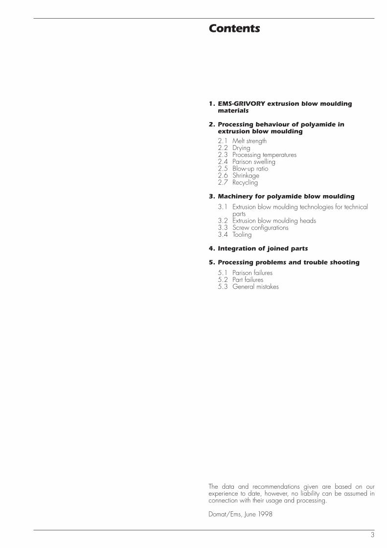
Fig. 1: Device for determining the melt strength by the EMS-GRIVORY method.
2.1. Melt strength
Very exacting requirements are imposed on the material whenprocessing polyamide by extrusion blow moulding. One of themost important properties is the melt strength.
The term melt strength describes the “stability” of the parison.With higher melt strength it remains dimensionally stable,whereas with low melt strength it elongates more.
Consequently, materials with high melt strength are needed forextrusion blow moulding.
For this EMS-GRIVORY has developed its own procedure toassess the melt strength. A tube is continuously extruded andthe time taken by the tube to cover the distance (1 metre) fromnozzle to floor is measured.
The melt strength is always measured with an output of 100cubic centimetres per minute and a fixed temperature profile.
5
Lupo
len 3
020
DG
rilon
EB 5
0 H
Grilo
n EB
50
HDZ
Grilo
n R
50 H
NZ
Grilo
n RV
Z-15H
.1G
rilon
EBV-1
5HG
rilon
EBV-2
H
Grilo
n EL
X 40
HN
Z
Grila
mid
L 25
ANZ
Grila
mid
L 20
ANZ
Grila
mid
LV-2
AN
Z70
80
90
100
110
120
Melt strength [%]
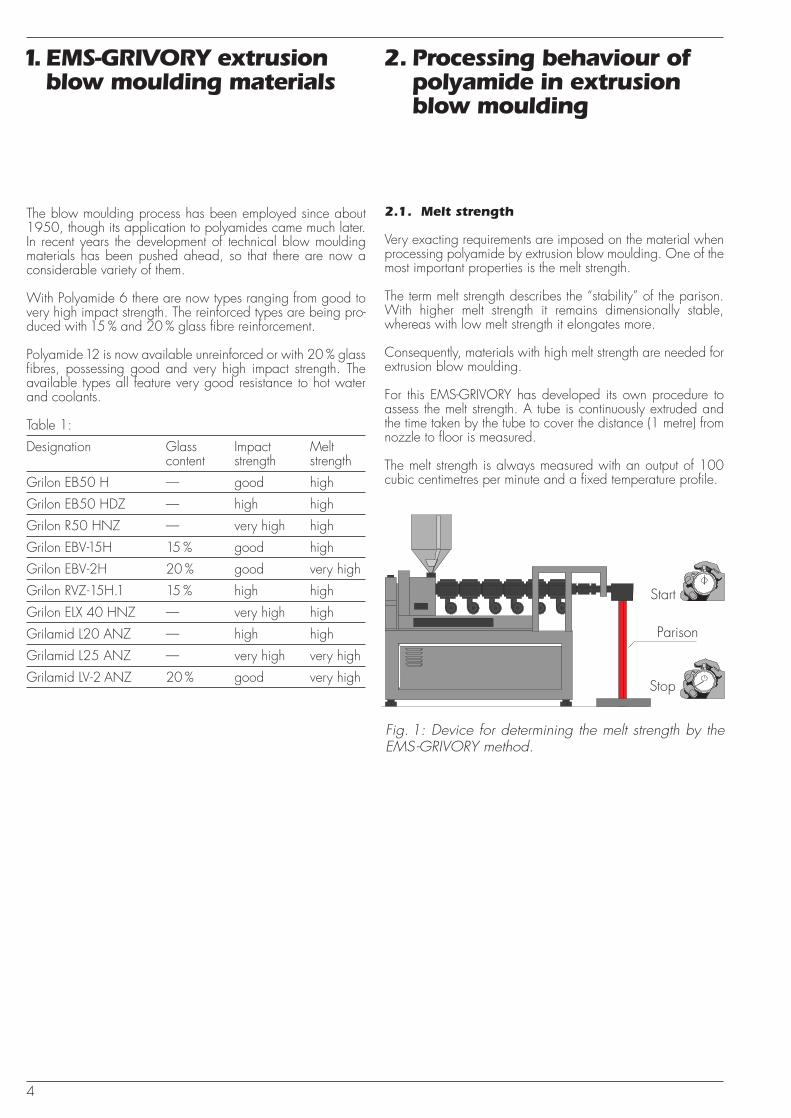
Fig. 2: Comparison of a standard PE - LD (at 210 °C melt temperature) with the EMS-GRIVORY blow moulding types (at 270 °C melt temperature).
Moisture content [%]
110
100
90
80
700 0.05 0.1 0.15 0.2
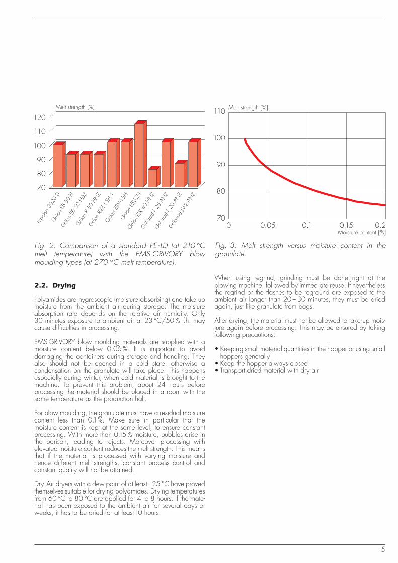
Fig. 3: Melt strength versus moisture content in the granulate.
Melt strength [%]
2.2. Drying
Polyamides are hygroscopic (moisture absorbing) and take upmoisture from the ambient air during storage. The moistureabsorption rate depends on the relative air humidity. Only30 minutes exposure to ambient air at 23 °C/50 % r.h. maycause difficulties in processing.
EMS-GRIVORY blow moulding materials are supplied with amoisture content below 0.06 %. It is important to avoiddamaging the containers during storage and handling. Theyalso should not be opened in a cold state, otherwise acondensation on the granulate will take place. This happensespecially during winter, when cold material is brought to themachine. To prevent this problem, about 24 hours beforeprocessing the material should be placed in a room with thesame temperature as the production hall.
For blow moulding, the granulate must have a residual moisturecontent less than 0.1%. Make sure in particular that themoisture content is kept at the same level, to ensure constantprocessing. With more than 0.15 % moisture, bubbles arise inthe parison, leading to rejects. Moreover processing withelevated moisture content reduces the melt strength. This meansthat if the material is processed with varying moisture andhence different melt strengths, constant process control andconstant quality will not be attained.
Dry -Air dryers with a dew point of at least –25 °C have provedthemselves suitable for drying polyamides. Drying temperaturesfrom 60 °C to 80 °C are applied for 4 to 8 hours. If the mate-rial has been exposed to the ambient air for several days orweeks, it has to be dried for at least10 hours.
When using regrind, grinding must be done right at theblowing machine, followed by immediate reuse. If neverthelessthe regrind or the flashes to be reground are exposed to theambient air longer than 20 – 30 minutes, they must be driedagain, just like granulate from bags.
After drying, the material must not be allowed to take up mois-ture again before processing. This may be ensured by takingfollowing precautions:
• Keeping small material quantities in the hopper or using smallhoppers generally
• Keep the hopper always closed• Transport dried material with dry air
6
Feed zone temperatures:
By using a grooved feeding zone, temperature control shouldrun with oil. If the machine has a smooth feed, a temperatureof 60 – 80 °C at the hopper may be run.
To ensure proper material conveying, a high feed zonetemperature must be chosen. Accordingly, the rule is: thedeeper the grooves, the higher the temperature should be.However, if the extruder still blocks, the material must be fed inslowly or preheated (about 120 to 130 °C).
Cylinder temperatures:
The cylinder temperatures must be selected so that the melt tem-perature does not have a bigger difference than10 –15 °C. Ifdeviation exceeds 15 °C, the cylinder temperature must bebrought into line. Generally speaking, very good results can beachieved with an elevated cylinder temperature at the first zonefollowed by a constant temperature profile. This temperatureprofile may differ depending on the screw geometry, but it mustbe optimized.
Head temperatures:
The head temperatures must be set according to the melttemperature. To check the parison swelling at the die, atemperature lower or higher than the melt temperature may berun. It should, however, not be too low if a good surface qualityis to be assured.
Mould temperatures:
Owing to the molecular chains of the extrusion blowing types,crystallization generally proceeds very slowly. Therefore blowmoulding polyamides can be processed with low mouldtemperatures and still achieve good product quality. Moreover,due to the unilateral one-side cooling in the mould, a slowercooling than in injection blow moulding and hence anadequate crystallization can be attained.
Blower
Thermostat
Drying granulate
Heating
Drying container
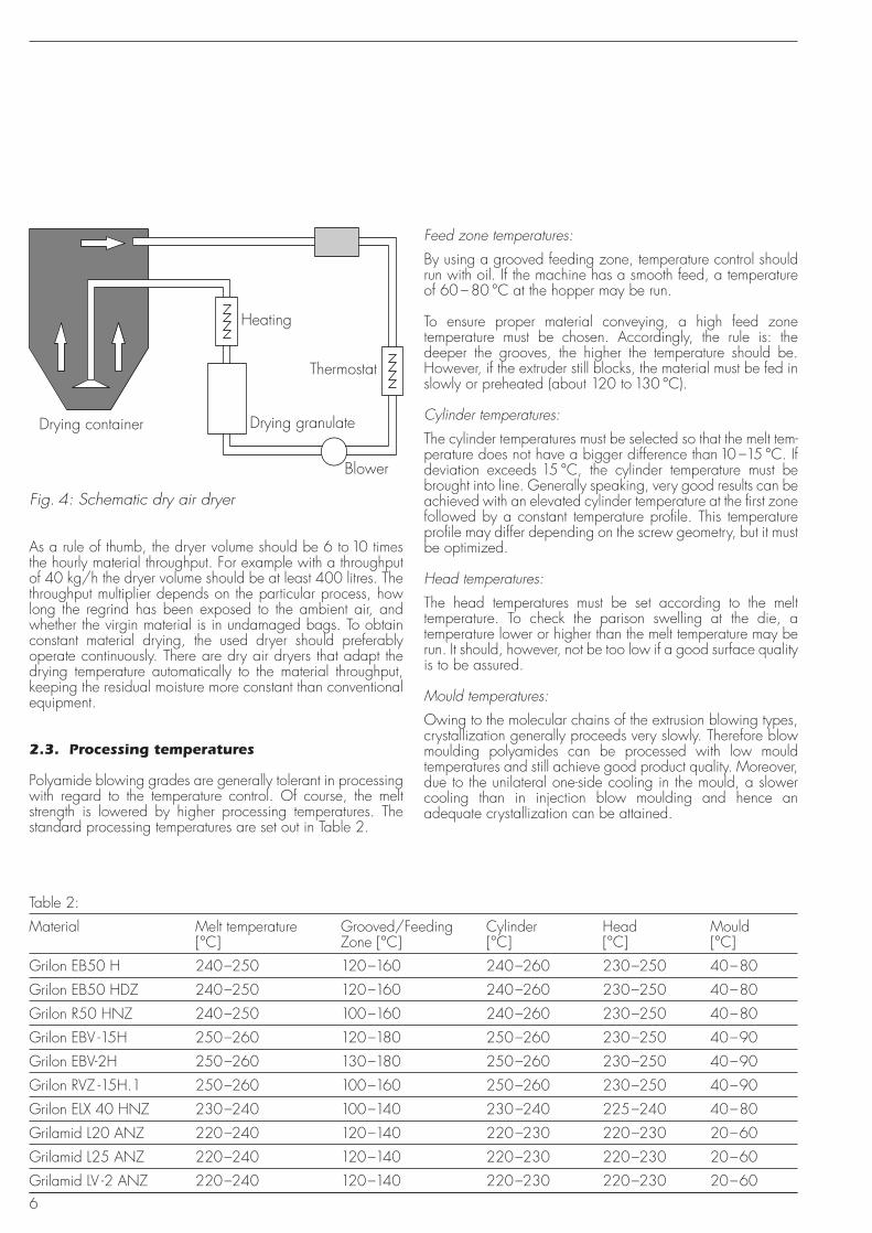
Fig. 4: Schematic dry air dryer
As a rule of thumb, the dryer volume should be 6 to 10 timesthe hourly material throughput. For example with a throughputof 40 kg/h the dryer volume should be at least 400 litres. Thethroughput multiplier depends on the particular process, howlong the regrind has been exposed to the ambient air, andwhether the virgin material is in undamaged bags. To obtainconstant material drying, the used dryer should preferablyoperate continuously. There are dry air dryers that adapt thedrying temperature automatically to the material throughput,keeping the residual moisture more constant than conventionalequipment.
2.3. Processing temperatures
Polyamide blowing grades are generally tolerant in processingwith regard to the temperature control. Of course, the meltstrength is lowered by higher processing temperatures. Thestandard processing temperatures are set out in Table 2.
Table 2:
Material Melt temperature Grooved/Feeding Cylinder Head Mould[°C] Zone [°C] [°C] [°C] [°C]
Grilon EB50 H 240–250 120–160 240–260 230–250 40–80
Grilon EB50 HDZ 240–250 120–160 240–260 230–250 40–80
Grilon R50 HNZ 240–250 100–160 240–260 230–250 40–80
Grilon EBV -15H 250–260 120–180 250–260 230–250 40–90
Grilon EBV-2H 250–260 130–180 250–260 230–250 40–90
Grilon RVZ -15H.1 250–260 100–160 250–260 230–250 40–90
Grilon ELX 40 HNZ 230–240 100–140 230–240 225–240 40–80
Grilamid L20 ANZ 220–240 120–140 220–230 220–230 20–60
Grilamid L25 ANZ 220–240 120–140 220–230 220–230 20–60
Grilamid LV -2 ANZ 220–240 120–140 220–230 220–230 20–60
7
Melt temperatures:
Through the melt temperature the melt strength can be adjustedwithin certain limits. Increasing the melt temperature by 20 °Cwill lower the melt strength by 20 –30 %. For the PA6 blowingtypes the melt temperature should always be above230 –235 °C if smooth surfaces are to be obtained.
2.4 Parison swelling
«Parison swelling» is defined as the change of diameter afterthe die exit. No values of general validity can be stated for it,because a great number of parameters are involved. Onlytendencies can be indicated here:
• The lower the melt temperature, the greater the swell(depending on the die geometry, see Fig. 5).
• The higher the melt strength, the greater the swell.• The higher the extrusion speed, the greater the swell.• The gentler and slower the melt is formed into the required
diameter, the less the swelling.
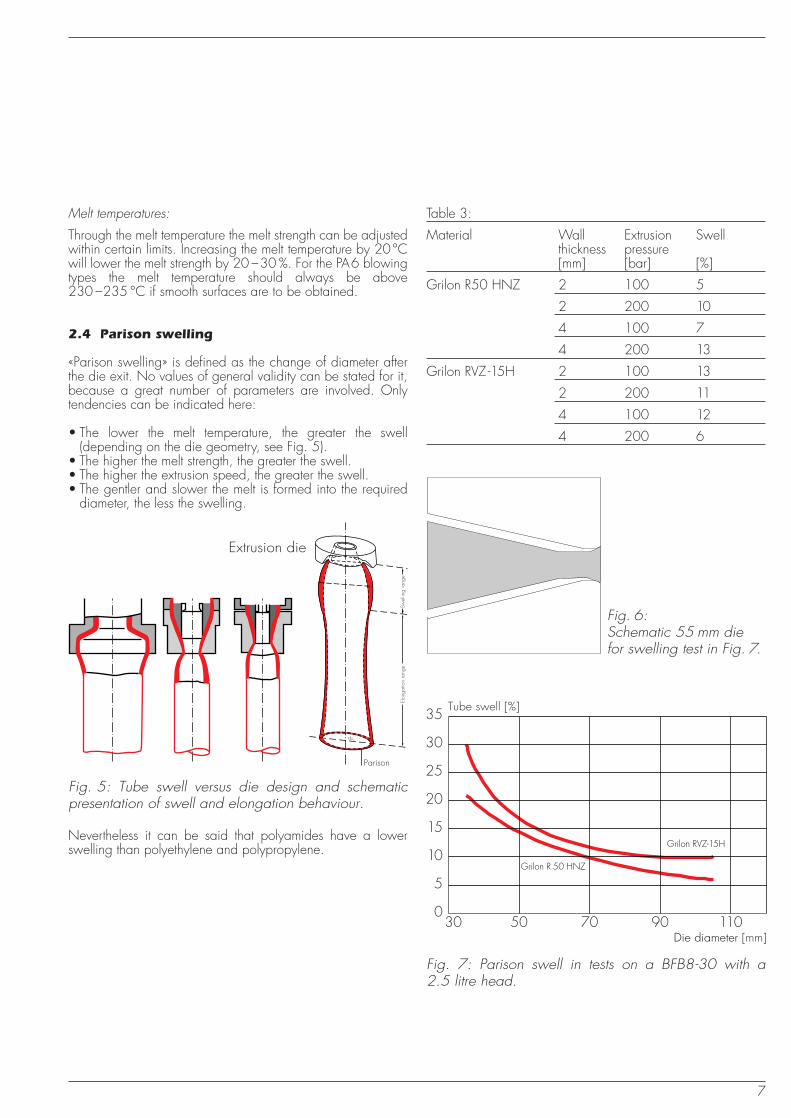
Table 3:
Material Wall Extrusion Swellthickness pressure[mm] [bar] [%]
Grilon R50 HNZ 2 100 5
2 200 10
4 100 7
4 200 13
Grilon RVZ -15H 2 100 13
2 200 11
4 100 12
4 200 6
Fig. 5: Tube swell versus die design and schematic presentation of swell and elongation behaviour.
Extrusion die
Swel
ling
rang
eEl
onga
tion
rang
e
Parison
ds2
Nevertheless it can be said that polyamides have a lowerswelling than polyethylene and polypropylene.
Fig. 6:Schematic 55 mm diefor swelling test in Fig. 7.
Grilon R 50 HNZ
Grilon RVZ-15H
35
30
30 50 70 90 110
25
20
15
10
5
0
Tube swell [%]
Die diameter [mm]
Fig. 7: Parison swell in tests on a BFB8-30 with a2.5 litre head.
8
2.5 Blow-up ratio
The «blow-up ratio» is defined as the ratio between thediameter of the parison and the diameter of the finished part.If the parison has a diameter of 60 mm and the finished part120 mm, the blow-up ratio is 2:1.
The blow-up ratio has considerable influence on the mechani-cal properties and above all on the shrinkage. It can be saidthat with an increasing blow-up ratio the orientation of themolecules and fibres increases in radial direction. This effectmay be used deliberately in order to obtain isotropic shrinkage(see Fig. 9) or improved orientation of glass fibres in radialdirection for example.
Even with unfavourable part geometry (e.g. sharp edges etc.)it is possible to achieve blow-up ratios of 4:1 with unreinforcedmaterials and 2:1 with reinforced materials. With an adequatepart geometry it may be possible to achieve higher blow-upratios, such as 6:1 with unreinforced materials and 4:1 withreinforced ones.
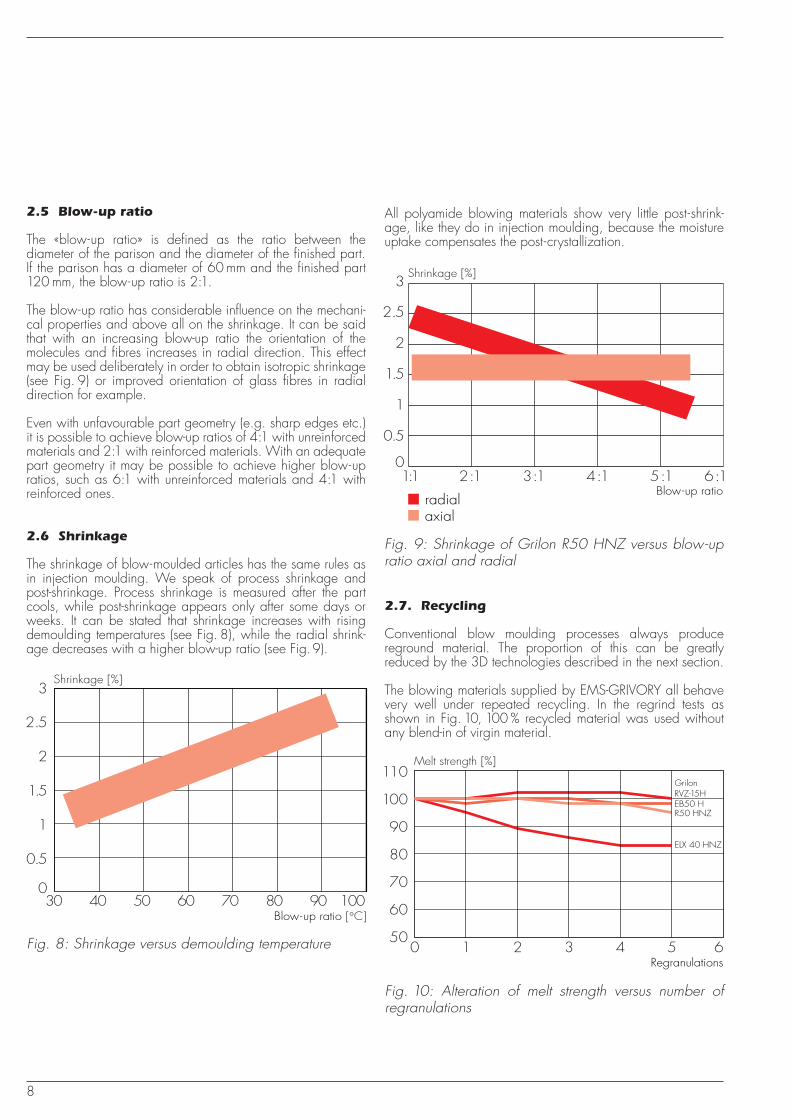
2.6 Shrinkage
The shrinkage of blow-moulded articles has the same rules asin injection moulding. We speak of process shrinkage andpost-shrinkage. Process shrinkage is measured after the partcools, while post-shrinkage appears only after some days orweeks. It can be stated that shrinkage increases with risingdemoulding temperatures (see Fig. 8), while the radial shrink-age decreases with a higher blow-up ratio (see Fig.9).
3
30 40 50 60 70 80 90 100
2.5
2
1.5
1
0.5
0
Shrinkage [%]
Blow-up ratio [°C]
Fig. 8: Shrinkage versus demoulding temperature
Shrinkage [%]
Blow-up ratio
3
1:1 2:1 3:1 4:1 5:1 6:1
2.5
2
1.5
1
0.5
0
radialaxial
Fig. 9: Shrinkage of Grilon R50 HNZ versus blow-up ratio axial and radial
All polyamide blowing materials show very little post-shrink-age, like they do in injection moulding, because the moistureuptake compensates the post-crystallization.
2.7. Recycling
Conventional blow moulding processes always producereground material. The proportion of this can be greatlyreduced by the 3D technologies described in the next section.
The blowing materials supplied by EMS-GRIVORY all behavevery well under repeated recycling. In the regrind tests asshown in Fig. 10, 100 % recycled material was used withoutany blend-in of virgin material.
Melt strength [%]
Regranulations
RVZ-15HGrilon
EB50 HR50 HNZ
ELX 40 HNZ
110
100
90
80
70
60
500 1 2 3 4 5 6
Fig. 10: Alteration of melt strength versus number of regranulations
9
3. Machinery for polyamideblow moulding
Hydrauliccylinder
Parison
Extruder
Mould
Blow mandrel and stretcher Parison gripper
Mould holding plateand clamping unit
Vertical andhorizontaladjustment
Feed hopper
Die head
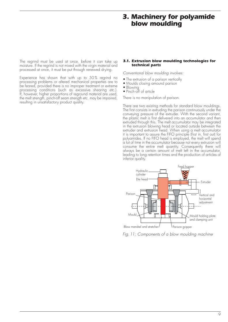
Fig. 11: Components of a blow moulding machine
The regrind must be used at once, before it can take upmoisture. If the regrind is not mixed with the virgin material andprocessed at once, it must be put through renewed drying.
Experience has shown that with up to 50 % regrind noprocessing problems or altered mechanical properties are tobe feared, provided there is no improper treatment or extremeprocessing conditions (such as excessive shearing etc.).If, however, higher proportions of reground material are used,the melt strength, pinch-off seam strength etc. may be impaired,resulting in unsatisfactory product quality.
3.1. Extrusion blow moulding technologies fortechnical parts
Conventional blow moulding involves:
• The extrusion of a parison vertically• Moulds closing amound parison• Blowing• Pinch-off of article
There is no manipulation of parison.
There are two existing methods for standard blow mouldings.The first consists in extruding the parison continuously under theconveying pressure of the extruder. With the second variant,the plastic melt is first delivered into an accumulator and thenextruded through this. The melt accumulator may be integratedin the extrusion blowing head or located outside between theextruder and extrusion head. When using a melt accumulatorit is important to assure the FIFO principle (first in, first out) forpolyamides. If no FIFO head is employed, the melt will spenda lot of time in the accumulator because not every extrusion willconsume the entire melt quantity. Consequently there willalways be a certain amount of melt left in the accumulator,leading to long retention times and the production of articles ofinferior quality.
10
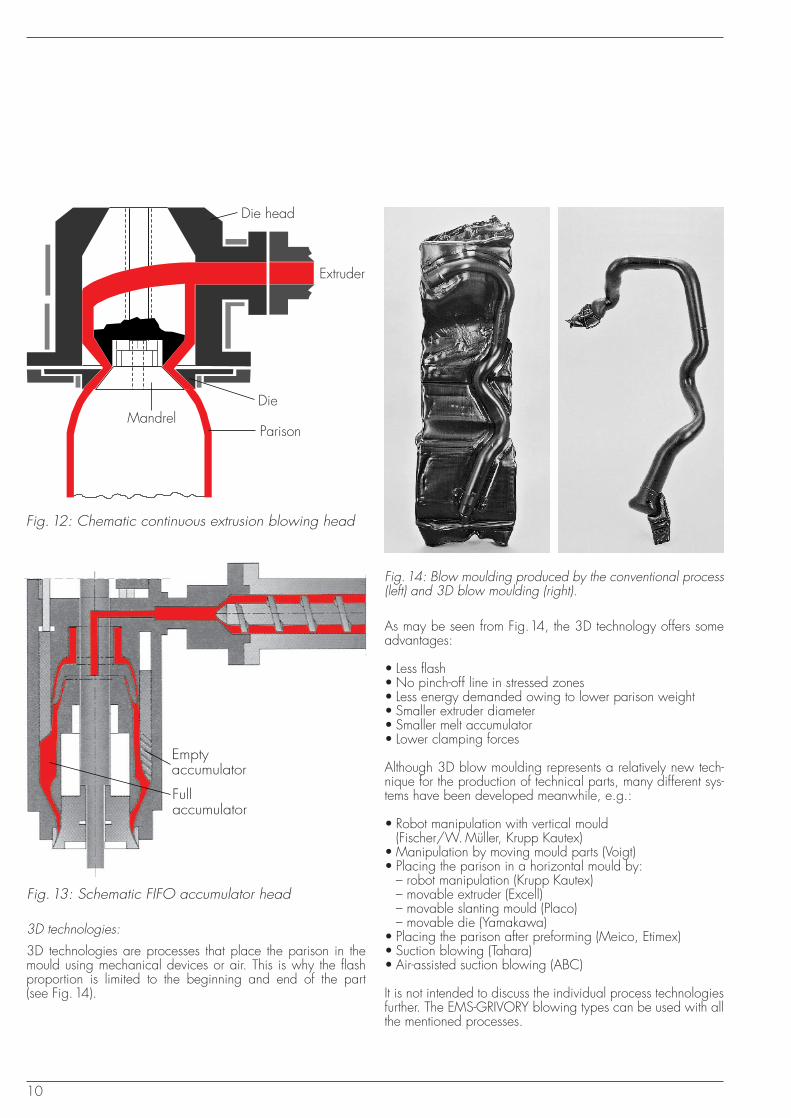
As may be seen from Fig.14, the 3D technology offers someadvantages:
• Less flash• No pinch-off line in stressed zones• Less energy demanded owing to lower parison weight• Smaller extruder diameter• Smaller melt accumulator• Lower clamping forces
Although 3D blow moulding represents a relatively new tech-nique for the production of technical parts, many different sys-tems have been developed meanwhile, e.g.:
• Robot manipulation with vertical mould(Fischer/W. Müller, Krupp Kautex)
• Manipulation by moving mould parts (Voigt)• Placing the parison in a horizontal mould by:
– robot manipulation (Krupp Kautex) – movable extruder (Excell)– movable slanting mould (Placo)– movable die (Yamakawa)
• Placing the parison after preforming (Meico, Etimex)• Suction blowing (Tahara)• Air-assisted suction blowing (ABC)
It is not intended to discuss the individual process technologiesfurther. The EMS-GRIVORY blowing types can be used with allthe mentioned processes.
Fig. 12: Chematic continuous extrusion blowing head
Die head
Extruder
Die
ParisonMandrel
Fig. 13: Schematic FIFO accumulator head
Emptyaccumulator
Fullaccumulator
Fig.14: Blow moulding produced by the conventional process(left) and 3D blow moulding (right).
3D technologies:
3D technologies are processes that place the parison in themould using mechanical devices or air. This is why the flashproportion is limited to the beginning and end of the part(see Fig.14).
11
ABC
ABA
A
B
C
t
VE
VE
t
Accumulator 1
Accumulator 2
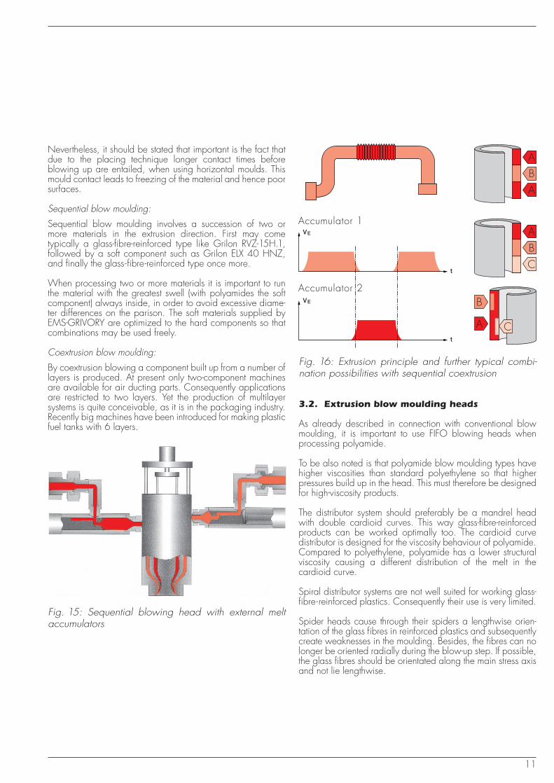
Fig. 16: Extrusion principle and further typical combi-nation possibilities with sequential coextrusion
Fig. 15: Sequential blowing head with external melt accumulators
3.2. Extrusion blow moulding heads
As already described in connection with conventional blowmoulding, it is important to use FIFO blowing heads whenprocessing polyamide.
To be also noted is that polyamide blow moulding types havehigher viscosities than standard polyethylene so that higherpressures build up in the head. This must therefore be designedfor high-viscosity products.
The distributor system should preferably be a mandrel headwith double cardioid curves. This way glass-fibre-reinforcedproducts can be worked optimally too. The cardioid curvedistributor is designed for the viscosity behaviour of polyamide.Compared to polyethylene, polyamide has a lower structuralviscosity causing a different distribution of the melt in thecardioid curve.
Spiral distributor systems are not well suited for working glass-fibre-reinforced plastics. Consequently their use is very limited.
Spider heads cause through their spiders a lengthwise orien-tation of the glass fibres in reinforced plastics and subsequentlycreate weaknesses in the moulding. Besides, the fibres can nolonger be oriented radially during the blow-up step. If possible,the glass fibres should be orientated along the main stress axisand not lie lengthwise.
Nevertheless, it should be stated that important is the fact thatdue to the placing technique longer contact times beforeblowing up are entailed, when using horizontal moulds. Thismould contact leads to freezing of the material and hence poorsurfaces.
Sequential blow moulding:
Sequential blow moulding involves a succession of two ormore materials in the extrusion direction. First may cometypically a glass-fibre-reinforced type like Grilon RVZ-15H.1,followed by a soft component such as Grilon ELX 40 HNZ,and finally the glass-fibre-reinforced type once more.
When processing two or more materials it is important to runthe material with the greatest swell (with polyamides the softcomponent) always inside, in order to avoid excessive diame-ter differences on the parison. The soft materials supplied byEMS-GRIVORY are optimized to the hard components so thatcombinations may be used freely.
Coextrusion blow moulding:
By coextrusion blowing a component built up from a number oflayers is produced. At present only two-component machinesare available for air ducting parts. Consequently applicationsare restricted to two layers. Yet the production of multilayersystems is quite conceivable, as it is in the packaging industry.Recently big machines have been introduced for making plasticfuel tanks with 6 layers.
12
3.3. Screw configuration
Screw geometry:
Various screw concepts are used, depending on the machinemaker. It can be claimed that EMS-GRIVORY blow mouldingmaterials may be used with almost any screw geometry.Nevertheless, some designs are better than others. For workingpolyamide optimally, the following facts are to be considered:
• Shearing must be kept low.• No mixing and/or shearing parts may be used.• Screw length should be 22 – 26 times the diameter.• A too short feed zone causes pulsating feed.• A too short compression zone will lead to poor melting and
low feed rates.• The higher the melting point, the longer the compression
zone must be.• The higher the material viscosity, the lower the compression
zone must be.
As already mentioned, there are various concepts. The simplestone employs the standard 3-zone screw without grooves like ininjection moulding. With this concept the melt temperature canbe easily controlled, allowing constant operation. None theless, it is marred by a lower feed rate than with a groovedfeeding zone.
Other machine makers generally use grooved feeding zones inconjunction with different screw concepts. One of these has a 3-zone screw with low compression(K=1.5 – 2). The usage of barrier screws has recently increasedand also has found its way to blowing machines as well.
The best way to arrive at an optimal plasticizer configuration isto talk to the machine supplier.
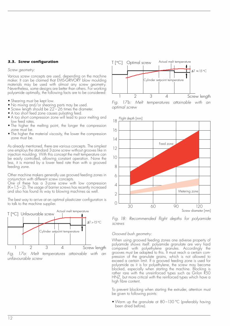
T [°C] Optimal screw
1 2 3 4Fig. 17b: Melt temperatures attainable with an optimal screw
Screw length
Actual melt temperature
Cylinder setpoint temperature
�T � 15 °C
Flight depth [mm]
Screw diameter [mm]
Feed zone
Metering zone
18
16
14
12
10
8
6
4
2
030 60 90 120
Fig. 18: Recommended flight depths for polyamide screws
Grooved bush geometry:
When using grooved feeding zones one adverse property ofpolyamide shows itself: polyamide granulate are very hardcompared with polyethylene granules. Accordingly thegrooves must be adapted to this. It must reach a certain com-pression of the granulate grains, which is not allowed toexceed a certain limit. If a grooved feeding zone is used forpolyamide as it is for polyethylene, the screw may becomeblocked, especially when starting the machine. Blocking israther rare with the unreinforced types such as Grilon R50HNZ, but more critical with the reinforced types which have ahigh fibre content.
To prevent blocking when starting the extruder, attention mustbe given to following points:
• Warm up the granulate at 80 –130 °C (preferably havingbeen dried before).
Fig. 17a: Melt temperatures attainable with an unfavourable screw
T [°C] Unfavourable screw
1 2 3 4 Screw length
Actual melt temperature
Cylinder setpoint temperature
�T > 15 °C
13
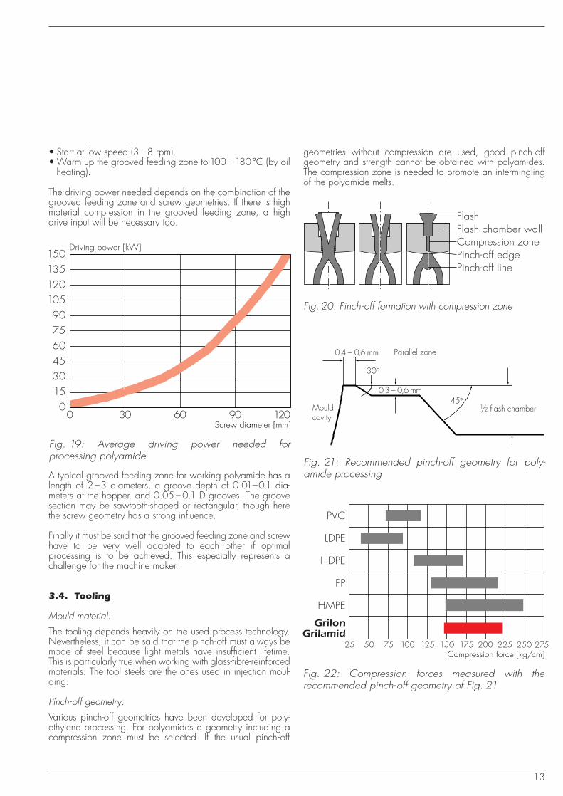
Driving power [kW]
Screw diameter [mm]
1501351201059075604530150
0 30 60 90 120
Fig. 19: Average driving power needed for processing polyamide
A typical grooved feeding zone for working polyamide has alength of 2 –3 diameters, a groove depth of 0.01–0.1 dia-meters at the hopper, and 0.05 – 0.1 D grooves. The groovesection may be sawtooth-shaped or rectangular, though herethe screw geometry has a strong influence.
Finally it must be said that the grooved feeding zone and screwhave to be very well adapted to each other if optimalprocessing is to be achieved. This especially represents achallenge for the machine maker.
3.4. Tooling
Mould material:
The tooling depends heavily on the used process technology.Nevertheless, it can be said that the pinch-off must always bemade of steel because light metals have insufficient lifetime.This is particularly true when working with glass-fibre-reinforcedmaterials. The tool steels are the ones used in injection moul-ding.
Pinch-off geometry:
Various pinch-off geometries have been developed for poly-ethylene processing. For polyamides a geometry including acompression zone must be selected. If the usual pinch-off
FlashFlash chamber wallCompression zonePinch-off edgePinch-off line
Fig. 21: Recommended pinch-off geometry for poly-amide processing
Mouldcavity
Parallel zone0,4 – 0,6 mm
30°
0,3 – 0,6 mm45°
1/2 flash chamber
Fig. 20: Pinch-off formation with compression zone
PVC
25 50 75 100 125 150 175 200 225 250 275
LDPE
HDPE
PP
HMPE
GrilonGrilamid
Compression force [kg/cm]
Fig. 22: Compression forces measured with the recommended pinch-off geometry of Fig. 21
• Start at low speed (3 – 8 rpm).• Warm up the grooved feeding zone to 100 –180 °C (by oil
heating).
The driving power needed depends on the combination of thegrooved feeding zone and screw geometries. If there is highmaterial compression in the grooved feeding zone, a highdrive input will be necessary too.
geometries without compression are used, good pinch-offgeometry and strength cannot be obtained with polyamides.The compression zone is needed to promote an interminglingof the polyamide melts.
14
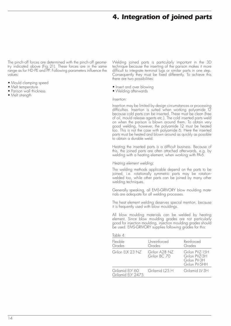
Welding joined parts is particularly important in the 3Dtechnique because the inserting of the parison makes it moredifficult to integrate terminal lugs or similar parts in one step.Consequently they must be fixed differently. To achieve thisthere are two possibilities:
• Insert and over blowing• Welding afterwards
Insertion:
Insertion may be limited by design circumstances or processingdifficulties. Insertion is suited when working polyamide 12because cold parts can be inserted. These must be clean (freeof oil, mould release agents etc.). The cold inserted parts weldon when the parison is blown around them. To obtain verygood welding, however, the polyamide 12 must be heatedtoo. This is not the case with polyamide 6. Here the insertedparts must be heated and blown around as quickly as possibleto obtain a durable weld.
Heating the inserted parts is a difficult business. Because ofthis, the joined parts are often attached afterwards, e.g. bywelding with a heating element, when working with PA6.
Heating element welding:
The welding methods applicable depend on the parts to bejoined, i.e. rotationally symmetric parts may be rotation-welded too, while other parts can be joined by many otherwelding techniques.
Generally speaking, all EMS-GRIVORY blow moulding mate-rials are adequate for all welding processes.
The heat element welding deserves special mention, becauseit is frequently used with blow mouldings.
All blow moulding materials can be welded by heatingelement. Since blow moulding grades are not particularlygood for injection moulding, injection moulding grades shouldbe used. EMS-GRIVORY supplies following grades for this:
Table 4:
Flexible Unreinforced ReinforcedGrades Grades Grades
Grilon ELX 23 NZ Grilon A28 NZ Grilon PVZ-15HGrilon BC 70 Grilon PVZ-3H
Grilon PV-3HGrilon PV-5HH
Grilamid ELY 60 Grilamid L25 H Grilamid LV-3HGrilamid ELY 2475
4. Integration of joined parts
The pinch-off forces are determined with the pinch-off geome-try indicated above (Fig. 21). These forces are in the samerange as for HD-PE and PP. Following parameters influence thevalues:
• Mould clamping speed• Melt temperature• Parison wall thickness• Melt strength
15
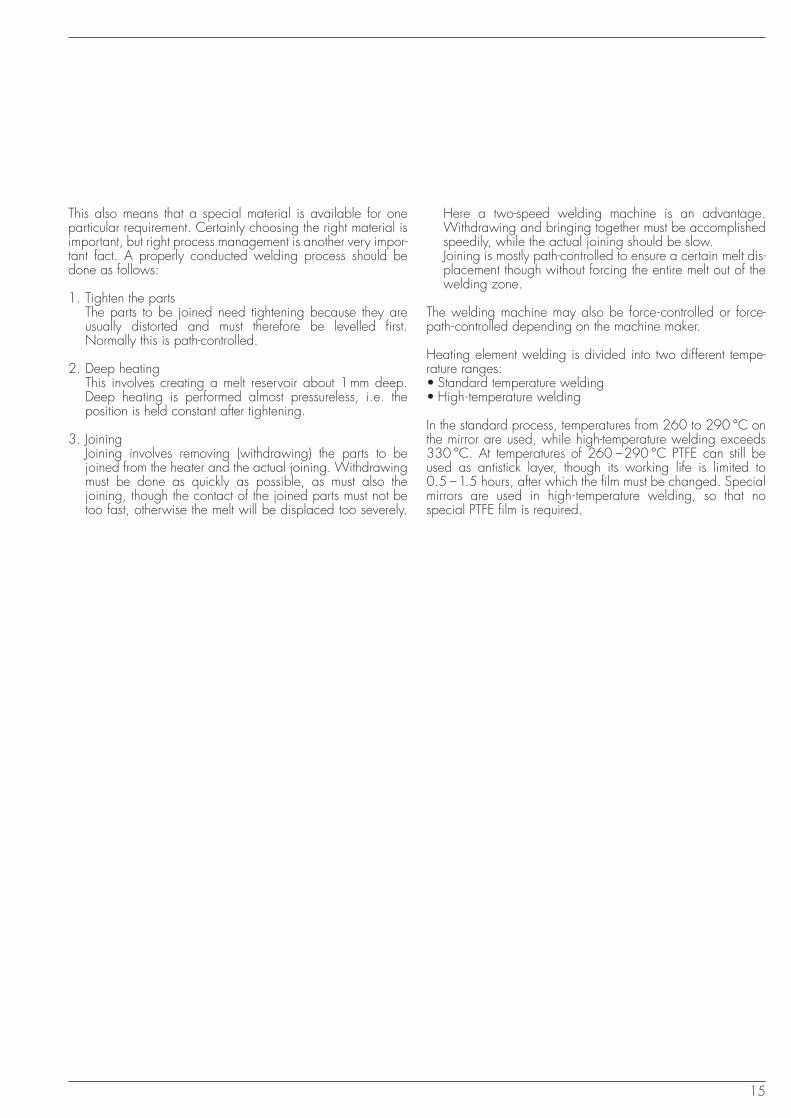
Here a two-speed welding machine is an advantage.Withdrawing and bringing together must be accomplishedspeedily, while the actual joining should be slow.Joining is mostly path-controlled to ensure a certain melt dis-placement though without forcing the entire melt out of thewelding zone.
The welding machine may also be force-controlled or force-path-controlled depending on the machine maker.
Heating element welding is divided into two different tempe-rature ranges:• Standard temperature welding• High-temperature welding
In the standard process, temperatures from 260 to 290 °C onthe mirror are used, while high-temperature welding exceeds330 °C. At temperatures of 260 –290 °C PTFE can still beused as antistick layer, though its working life is limited to0.5 –1.5 hours, after which the film must be changed. Specialmirrors are used in high-temperature welding, so that nospecial PTFE film is required.
This also means that a special material is available for oneparticular requirement. Certainly choosing the right material isimportant, but right process management is another very impor-tant fact. A properly conducted welding process should bedone as follows:
1. Tighten the parts The parts to be joined need tightening because they areusually distorted and must therefore be levelled first.Normally this is path-controlled.
2. Deep heating This involves creating a melt reservoir about 1mm deep.Deep heating is performed almost pressureless, i.e. theposition is held constant after tightening.
3. JoiningJoining involves removing (withdrawing) the parts to bejoined from the heater and the actual joining. Withdrawingmust be done as quickly as possible, as must also thejoining, though the contact of the joined parts must not betoo fast, otherwise the melt will be displaced too severely.
16
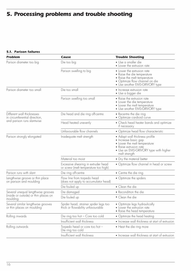
5.1. Parison failures
Problem Cause Trouble Shooting
Parison diameter too big Die too big • Use a smaller die• Lower the extrusion rate
Parison swelling to big • Lower the extrusion rate• Raise the die temperature• Raise the melt temperature• Optimize flow channel on die• Use another EMS-GRIVORY type
Parison diameter too small Die too small • Increase extrusion rate• Use a bigger die
Parison swelling too small • Raise the extrusion rate• Lower the die temperature• Lower the melt temperature• Use another EMS-GRIVORY type
Different wall thicknesses Die head and die ring off-centre • Recentre the die ringin circumferential direction, • Optimize cardioid curveand parison runs slantwise Head heated unevenly • Check head heater bands and optimize
if necessary
Unfavourable flow channels • Optimize head flow characteristic
Parison strongly elongated Inadequate melt strength • Adapt wall thickness profile• Increase basic gap• Lower the melt temperature• Raise extrusion rate• Use an EMS-GRIVORY type with higher
melt strength
Material too moist • Dry the material better
Excessive shearing in extruder head • Optimize flow channel in head or screwor screw (melt temperature too high)
Parison runs with slant Die ring off-centre • Centre the die ring
Lengthwise groove or thin place Flow line from torpedo head • Optimize the spiderson parison and moulding (does not apply to accumulator head)
Die fouled up • Clean the die
Several unequal lengthwise grooves Die damaged • Recondition the die(inside or outside) or thin places on Die fouled up • Clean the diemoulding
Several similar lengthwise grooves Spider head, strainer spider legs too • Optimize legs hydraulicallyor thin places on moulding thick or flowability unfavourable • Lower the extrusion rate
• Raise the head temperature
Rolling inwards Die ring too hot – Core too cold • Optimize the head heating
Insufficient wall thickness • Increase wall thickness at start of extrusion
Rolling outwards Torpedo head or core too hot – • Heat the die ring moreDie ring too cold
Insufficient wall thickness • Increase wall thickness at start of extrusion
5. Processing problems and trouble shooting
17
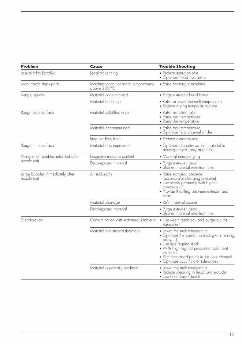
Problem Cause Trouble Shooting
Lateral folds (locally) Local advancing • Reduce extrusion rate• Optimize head hydraulics
Local rough strips parts Machine does not reach temperatures • Raise heating of machineabove 230 °C
Lumps, specks Material contaminated • Purge extruder/head longer
Material builds up • Raise or lower the melt temperature• Reduce drying temperature/time
Rough outer surface Material solidifies in air • Raise extrusion rate• Raise melt temperature• Raise die temperature
Material decompressed • Raise melt temperature• Optimize flow channel of die
Irregular flow front • Reduce extrusion rate
Rough inner surface Material decompressed • Optimize die entry so that material isdecompressed only at die exit
Many small bubbles retarded after Excessive moisture content • Material needs dryingnozzle exit Decomposed material • Purge extruder, head
• Shorten material retention time
Large bubbles immediately after Air inclusions • Raise extrusion pressurenozzle exit (accumulator charging pressure)
• Use screw geometry with highercompression
• Provide throttling between extruder andhead
Material shortage • Refill material sooner
Decomposed material • Purge extruder, head• Shorten material retention time
Discoloration Contamination with extraneous material • Use virgin feedstock and purge out theequipment
Material overstresed thermally • Lower the melt temperature• Optimize the screw (no mixing or shearing
parts,...)• Use less regrind stock• With high regrind proportion add heat
stabilizer• Eliminate dead points in the flow channel• Optimize accumulator tolerances
Material is partially oxidized • Lower the melt temperature• Reduce shearing in head and extruder• Use heat master batch
18
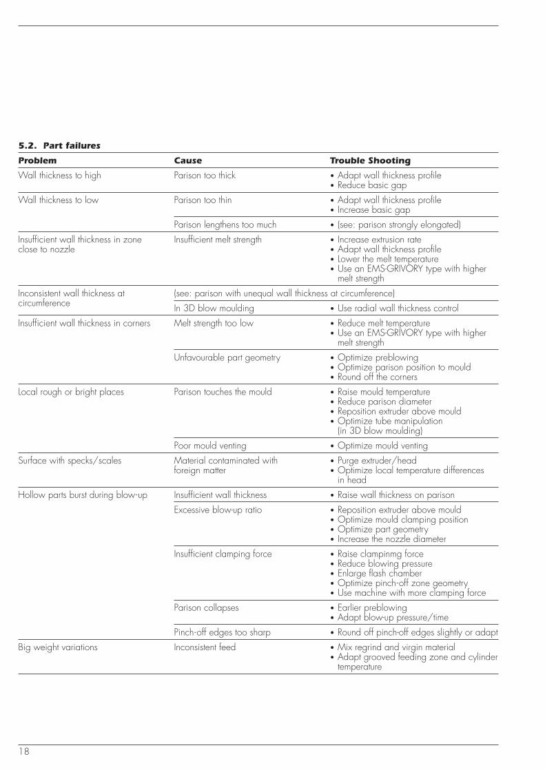
5.2. Part failures
Problem Cause Trouble Shooting
Wall thickness to high Parison too thick • Adapt wall thickness profile• Reduce basic gap
Wall thickness to low Parison too thin • Adapt wall thickness profile• Increase basic gap
Parison lengthens too much • (see: parison strongly elongated)
Insufficient wall thickness in zone Insufficient melt strength • Increase extrusion rateclose to nozzle • Adapt wall thickness profile
• Lower the melt temperature• Use an EMS-GRIVORY type with higher
melt strength
Inconsistent wall thickness at (see: parison with unequal wall thickness at circumference)circumference In 3D blow moulding • Use radial wall thickness control
Insufficient wall thickness in corners Melt strength too low • Reduce melt temperature• Use an EMS-GRIVORY type with higher
melt strength
Unfavourable part geometry • Optimize preblowing• Optimize parison position to mould• Round off the corners
Local rough or bright places Parison touches the mould • Raise mould temperature• Reduce parison diameter• Reposition extruder above mould• Optimize tube manipulation
(in 3D blow moulding)
Poor mould venting • Optimize mould venting
Surface with specks/scales Material contaminated with • Purge extruder/headforeign matter • Optimize local temperature differences
in head
Hollow parts burst during blow-up Insufficient wall thickness • Raise wall thickness on parison
Excessive blow-up ratio • Reposition extruder above mould• Optimize mould clamping position• Optimize part geometry• Increase the nozzle diameter
Insufficient clamping force • Raise clampinmg force• Reduce blowing pressure• Enlarge flash chamber• Optimize pinch-off zone geometry• Use machine with more clamping force
Parison collapses • Earlier preblowing• Adapt blow-up pressure/time
Pinch-off edges too sharp • Round off pinch-off edges slightly or adapt
Big weight variations Inconsistent feed • Mix regrind and virgin material• Adapt grooved feeding zone and cylinder
temperature
19
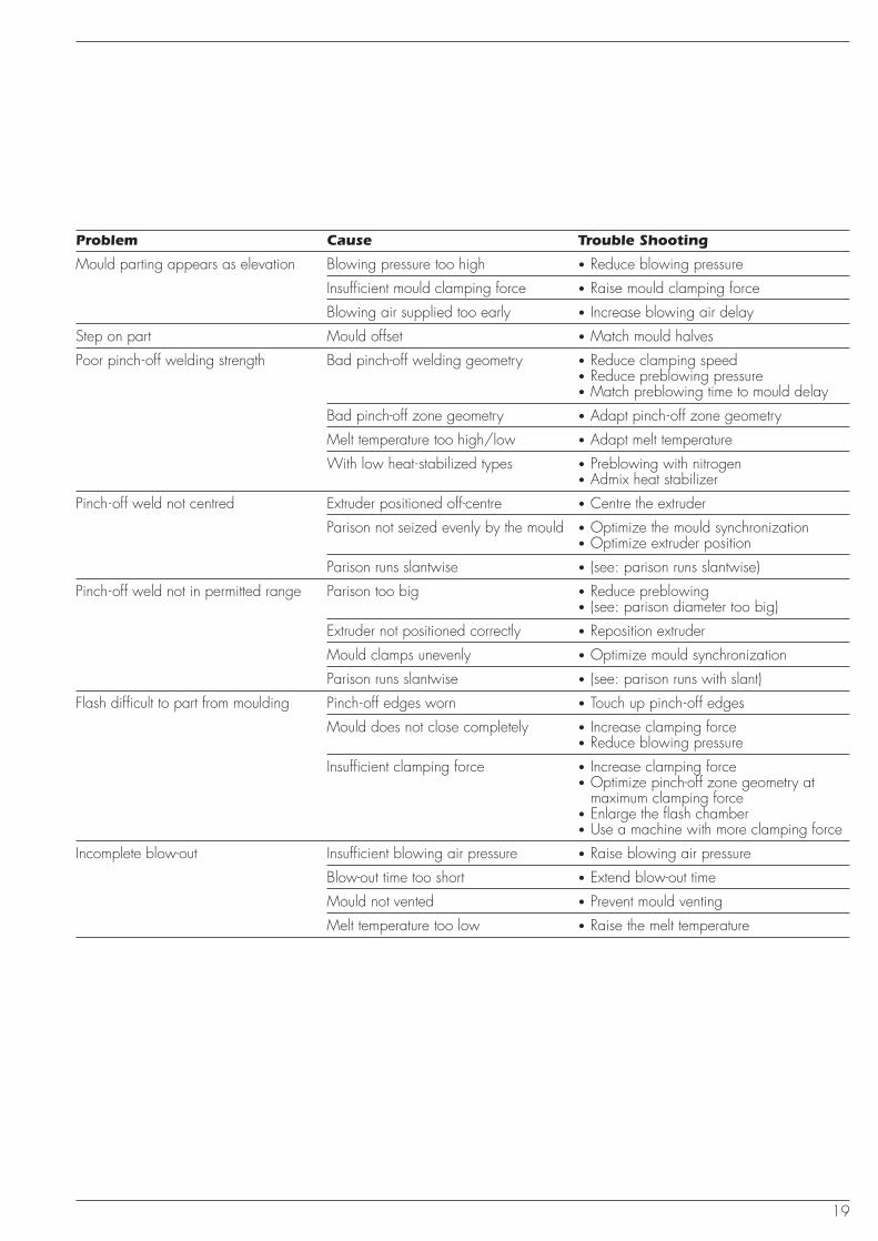
Problem Cause Trouble Shooting
Mould parting appears as elevation Blowing pressure too high • Reduce blowing pressure
Insufficient mould clamping force • Raise mould clamping force
Blowing air supplied too early • Increase blowing air delay
Step on part Mould offset • Match mould halves
Poor pinch-off welding strength Bad pinch-off welding geometry • Reduce clamping speed• Reduce preblowing pressure• Match preblowing time to mould delay
Bad pinch-off zone geometry • Adapt pinch-off zone geometry
Melt temperature too high/low • Adapt melt temperature
With low heat-stabilized types • Preblowing with nitrogen• Admix heat stabilizer
Pinch-off weld not centred Extruder positioned off-centre • Centre the extruder
Parison not seized evenly by the mould • Optimize the mould synchronization• Optimize extruder position
Parison runs slantwise • (see: parison runs slantwise)
Pinch-off weld not in permitted range Parison too big • Reduce preblowing• (see: parison diameter too big)
Extruder not positioned correctly • Reposition extruder
Mould clamps unevenly • Optimize mould synchronization
Parison runs slantwise • (see: parison runs with slant)
Flash difficult to part from moulding Pinch-off edges worn • Touch up pinch-off edges
Mould does not close completely • Increase clamping force• Reduce blowing pressure
Insufficient clamping force • Increase clamping force• Optimize pinch-off zone geometry at
maximum clamping force• Enlarge the flash chamber• Use a machine with more clamping force
Incomplete blow-out Insufficient blowing air pressure • Raise blowing air pressure
Blow-out time too short • Extend blow-out time
Mould not vented • Prevent mould venting
Melt temperature too low • Raise the melt temperature
20
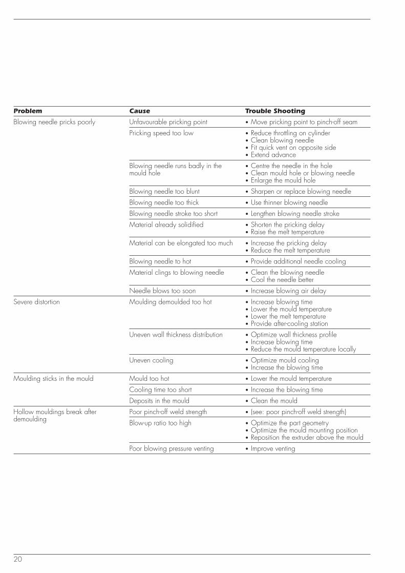
Problem Cause Trouble Shooting
Blowing needle pricks poorly Unfavourable pricking point • Move pricking point to pinch-off seam
Pricking speed too low • Reduce throttling on cylinder• Clean blowing needle• Fit quick vent on opposite side• Extend advance
Blowing needle runs badly in the • Centre the needle in the holemould hole • Clean mould hole or blowing needle
• Enlarge the mould hole
Blowing needle too blunt • Sharpen or replace blowing needle
Blowing needle too thick • Use thinner blowing needle
Blowing needle stroke too short • Lengthen blowing needle stroke
Material already solidified • Shorten the pricking delay• Raise the melt temperature
Material can be elongated too much • Increase the pricking delay• Reduce the melt temperature
Blowing needle to hot • Provide additional needle cooling
Material clings to blowing needle • Clean the blowing needle• Cool the needle better
Needle blows too soon • Increase blowing air delay
Severe distortion Moulding demoulded too hot • Increase blowing time• Lower the mould temperature• Lower the melt temperature• Provide after-cooling station
Uneven wall thickness distribution • Optimize wall thickness profile• Increase blowing time• Reduce the mould temperature locally
Uneven cooling • Optimize mould cooling• Increase the blowing time
Moulding sticks in the mould Mould too hot • Lower the mould temperature
Cooling time too short • Increase the blowing time
Deposits in the mould • Clean the mould
Hollow mouldings break after Poor pinch-off weld strength • (see: poor pinch-off weld strength)demoulding Blow-up ratio too high • Optimize the part geometry
• Optimize the mould mounting position• Reposition the extruder above the mould
Poor blowing pressure venting • Improve venting
21
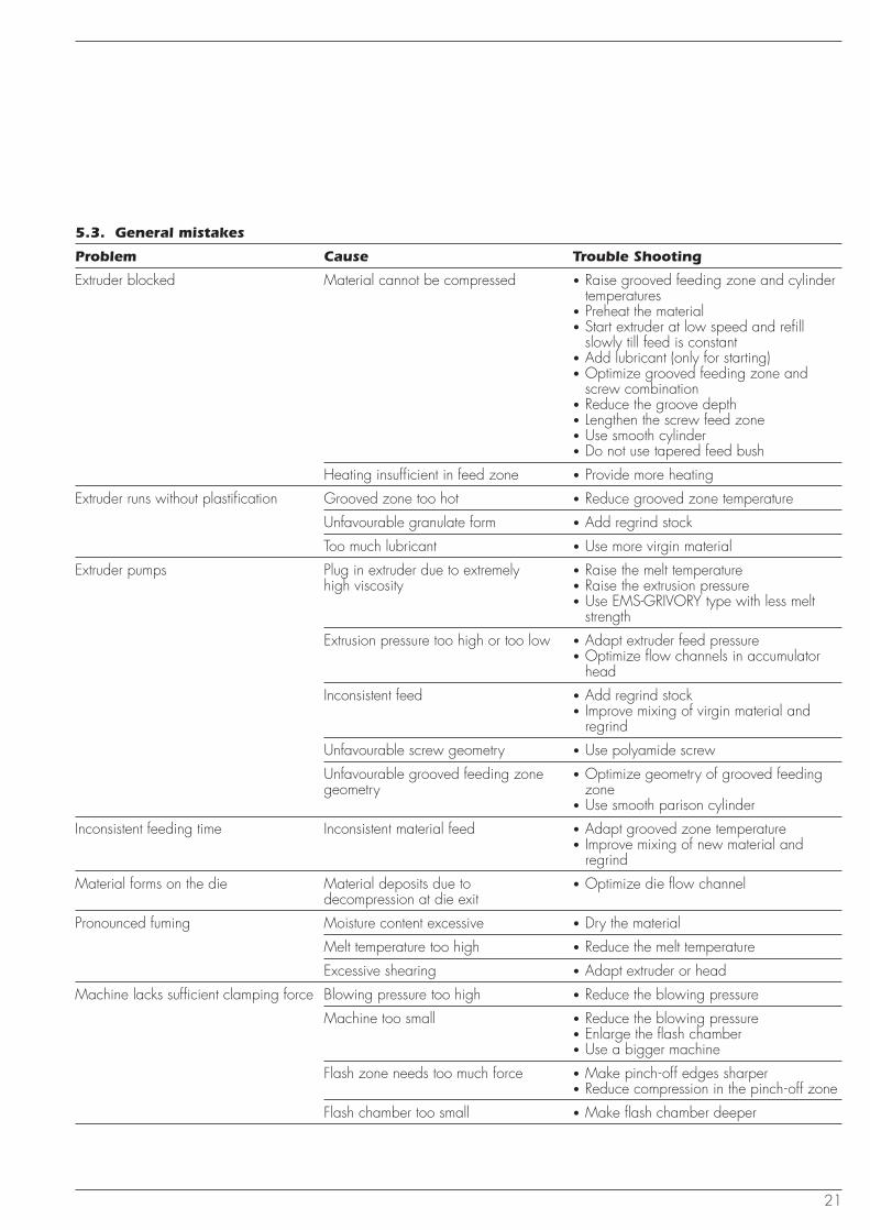
5.3. General mistakes
Problem Cause Trouble Shooting
Extruder blocked Material cannot be compressed • Raise grooved feeding zone and cylindertemperatures
• Preheat the material• Start extruder at low speed and refill
slowly till feed is constant• Add lubricant (only for starting)• Optimize grooved feeding zone and
screw combination• Reduce the groove depth• Lengthen the screw feed zone• Use smooth cylinder• Do not use tapered feed bush
Heating insufficient in feed zone • Provide more heating
Extruder runs without plastification Grooved zone too hot • Reduce grooved zone temperature
Unfavourable granulate form • Add regrind stock
Too much lubricant • Use more virgin material
Extruder pumps Plug in extruder due to extremely • Raise the melt temperaturehigh viscosity • Raise the extrusion pressure
• Use EMS-GRIVORY type with less meltstrength
Extrusion pressure too high or too low • Adapt extruder feed pressure• Optimize flow channels in accumulator
head
Inconsistent feed • Add regrind stock• Improve mixing of virgin material and
regrind
Unfavourable screw geometry • Use polyamide screw
Unfavourable grooved feeding zone • Optimize geometry of grooved feedinggeometry zone
• Use smooth parison cylinder
Inconsistent feeding time Inconsistent material feed • Adapt grooved zone temperature• Improve mixing of new material and
regrind
Material forms on the die Material deposits due to • Optimize die flow channeldecompression at die exit
Pronounced fuming Moisture content excessive • Dry the material
Melt temperature too high • Reduce the melt temperature
Excessive shearing • Adapt extruder or head
Machine lacks sufficient clamping force Blowing pressure too high • Reduce the blowing pressure
Machine too small • Reduce the blowing pressure• Enlarge the flash chamber• Use a bigger machine
Flash zone needs too much force • Make pinch-off edges sharper• Reduce compression in the pinch-off zone
Flash chamber too small • Make flash chamber deeper
7.00
3e
6.98
1000
AD
E
EMS-GRIVORY worldwidewww.emsgrivory.com
Switzerland
EMS-GRIVORY
CH-7013 Domat/EmsTel. +41 81 632 78 88Fax +41 81 632 74 01a unit of EMS-CHEMIE AGE-Mail: [email protected]
Germany
EMS-CHEMIE (Deutschland) GmbHBusiness Unit EMS-GRIVORYWarthweg 14D-64823 Gross -UmstadtTel. +49 6078 78 30Fax +49 6078 783 416E-Mail: [email protected]
France
EMS-CHEMIE (France) S.A.Division EMS-GRIVORY73-77, rue de SèvresBoîte postale 52F-92105 Boulogne-BillancourtTel. +33 1 41 10 06 10Fax +33 1 48 25 56 07E-Mail: [email protected]
Great Britain
EMS-CHEMIE (UK) Ltd.Business Unit EMS-GRIVORYDrummond RoadAstonfields Industrial EstateGB-Stafford ST16 3HJTel. +44 1785 607 580Fax +44 1785 607 570E-Mail: [email protected]
United States
EMS-CHEMIE (North America) Inc.Business Unit EMS-GRIVORY2060 Corporate WayP.O. Box 1717Sumter, SC 29151, USA Tel. +1 803 481 91 73Fax +1 803 481 38 20E-Mail: [email protected]
Taiwan
EMS-CHEMIE (Asia) Ltd.Business Unit EMS-GRIVORY36, Kwang Fu South RoadHsin Chu Industrial ParkFu Kou Hsiang, Hsin Chu HsienTaiwan, R.O.C.Tel. +886 35 985 335Fax +886 35 985 345E-Mail: [email protected]
Japan
EC-SHOWA DENKO K.K.Business Unit EMS -GRIVORYYutaka Bldg.4-9-3 TaitoTaito-ku110 -0016, Tokyo, JapanTel. +81 3 3832 1501Fax +81 3 3832 1503E-Mail: [email protected]
The recommendations anddata given are based on ourexperience today; however,no liability can be assumedin connection with their usageand processing.
Domat/Ems, November 2002 EMS-GRIVORY
Via Innovativa 1
EMS-GRIVORY EuropeSwitzerlandEMS-CHEMIE AG Business Unit EMS-GRIVORY Europe Via Innovativa 1 7013 Domat/Ems Switzerland Phone +41 81 632 78 88 Fax +41 81 632 76 65 [email protected]
GermanyEMS-CHEMIE (Deutschland) Vertriebs GmbH Warthweg 14 64823 Gross-Umstadt Deutschland Phone +49 6078 783 0 Fax +49 6078 783 416 [email protected]
FranceEMS-CHEMIE (France) S.A. 855 Avenue Roger Salengro Boîte postale 16 92370 Chaville France Phone +33 1 41 10 06 10 Fax +33 1 48 25 56 07 [email protected]
Great BritainEMS-CHEMIE (UK) Ltd. Darfin House, Priestly Court Staffordshire Technology Park Stafford ST18 0AR Great Britain Phone +44 1785 283 739 Fax +44 1785 283 722 [email protected]
EMS-GRIVORY, a business unit of the EMS Group
ItalyEMS-CHEMIE (Italia) S.r.l. Viale Innocenzo XI n. 77 22100 Como (CO) Italia Phone +41 81 632 75 25 Fax +41 81 632 74 54 [email protected]
EMS-GRIVORY AsiaChinaEMS-CHEMIE (China) Ltd. 227 Songbei Road Suzhou Industrial Park Suzhou City 215126 Jiangsu Province P.R. China Phone +86 512 8666 8180 Fax +86 512 8666 8210 [email protected]
EMS-CHEMIE (Suzhou) Ltd. 227 Songbei Road Suzhou Industrial Park Suzhou City 215126 Jiangsu Province P.R. China Phone +86 512 8666 8181 Fax +86 512 8666 8183 [email protected]
TaiwanEMS-CHEMIE (Taiwan) Ltd. 36, Kwang Fu South Road Hsin Chu Industrial Park Fu Kou Hsiang Hsin Chu Hsien 30351 Taiwan, R.O.C. Phone +886 3 598 5335 Fax +886 3 598 5345 [email protected]
KoreaEMS-CHEMIE (Korea) Ltd. #817 Doosan Venturedigm, 415 Heungan Daero, Dongan-gu, Anyang-si, Gyeonggi-do, 431-755 Republic of Korea Phone +82 31 478 3159 Fax +82 31 478 3157 [email protected]
JapanEMS-CHEMIE (Japan) Ltd. EMS Building 2-11-20 Higashi-koujiya Ota-ku, Tokyo 144-0033 Japan Phone +81 3 5735 0611 Fax +81 3 5735 0614 [email protected]
EMS-GRIVORY AmericaUnited States of AmericaEMS-CHEMIE (North America) Inc. 2060 Corporate Way P.O. Box 1717 Sumter, SC 29151 USA Phone +1 803 481 61 71 Fax +1 803 481 61 21 [email protected]
EMS-GRIVORY EuropeSwitzerlandEMS-CHEMIE AG Business Unit EMS-GRIVORY Europe Via Innovativa 1 7013 Domat/Ems Switzerland Phone +41 81 632 78 88 Fax +41 81 632 76 65 [email protected]
GermanyEMS-CHEMIE (Deutschland) Vertriebs GmbH Warthweg 14 64823 Gross-Umstadt Deutschland Phone +49 6078 783 0 Fax +49 6078 783 416 [email protected]
FranceEMS-CHEMIE (France) S.A. 855 Avenue Roger Salengro Boîte postale 16 92370 Chaville France Phone +33 1 41 10 06 10 Fax +33 1 48 25 56 07 [email protected]
Great BritainEMS-CHEMIE (UK) Ltd. Darfin House, Priestly Court Staffordshire Technology Park Stafford ST18 0LQ Great Britain Phone +44 1785 283 739 Fax +44 1785 283 722 [email protected]
EMS-GRIVORY, a business unit of the EMS Group
ItalyEMS-CHEMIE (Italia) S.r.l. Via Carloni 56 22100 Como (CO) Italia Phone +39 011 0604522 Fax +39 011 0604522 [email protected]
EMS-GRIVORY AsiaChinaEMS-CHEMIE (China) Ltd. 227 Songbei Road Suzhou Industrial Park Suzhou City 215126 Jiangsu Province P.R. China Phone +86 512 8666 8180 Fax +86 512 8666 8210 [email protected]
EMS-CHEMIE (Suzhou) Ltd. 227 Songbei Road Suzhou Industrial Park Suzhou City 215126 Jiangsu Province P.R. China Phone +86 512 8666 8181 Fax +86 512 8666 8183 [email protected]
TaiwanEMS-CHEMIE (Taiwan) Ltd. 36, Kwang Fu South Road Hsin Chu Industrial Park Fu Kou Hsiang Hsin Chu Hsien 30351 Taiwan, R.O.C. Phone +886 3 598 5335 Fax +886 3 598 5345 [email protected]
KoreaEMS-CHEMIE (Korea) Ltd. #817 Doosan Venturedigm, 415 Heungan Daero, Dongan-gu, Anyang-si, Gyeonggi-do, 431-755 Republic of Korea Phone +82 31 478 3159 Fax +82 31 478 3157 [email protected]
JapanEMS-CHEMIE (Japan) Ltd. EMS Building 2-11-20 Higashi-koujiya Ota-ku, Tokyo 144-0033 Japan Phone +81 3 5735 0611 Fax +81 3 5735 0614 [email protected]
EMS-GRIVORY AmericaUnited States of AmericaEMS-CHEMIE (North America) Inc. 2060 Corporate Way P.O. Box 1717 Sumter, SC 29151 USA Phone +1 803 481 61 71 Fax +1 803 481 61 21 [email protected]