
Technical Data and Specifications - Eatonpub/@eatonca/@elec/document… · CA08100012E—November...
78
Volume 10—Enclosed Control CA08100012E—November 2012 www.eaton.com V10-T17-1 17 17 17 17 17 17 17 17 17 17 17 17 17 17 17 17 17 17 17 17 17 17 17 17 17 17 17 17 17 17 Technical Data and Specifications NEMA Freedom Combination Starter IEC Contactors and Starter Lighting Contactor S801+ and S811+ Combination Soft Starters Control Power Transformer Kit 17.1 General Standards and Ratings Standards and Certifications . . . . . . . . . . . . . . . . . . . . . . . . . . . . . . . . V10-T17-2 Short-Circuit Testing . . . . . . . . . . . . . . . . . . . . . . . . . . . . . . . . . . . . . . V10-T17-2 17.2 NEMA Contactors and Starters Freedom Line . . . . . . . . . . . . . . . . . . . . . . . . . . . . . . . . . . . . . . . . . . . . V10-T17-3 17.3 IEC Contactors and Starters XT Line . . . . . . . . . . . . . . . . . . . . . . . . . . . . . . . . . . . . . . . . . . . . . . . . V10-T17-11 17.4 Solid State Overload Relay C440/XTOE . . . . . . . . . . . . . . . . . . . . . . . . . . . . . . . . . . . . . . . . . . . . . V10-T17-36 17.5 Lighting Contactors C30CN Lighting Contactors . . . . . . . . . . . . . . . . . . . . . . . . . . . . . . . . . V10-T17-39 A202 Lighting Contactors . . . . . . . . . . . . . . . . . . . . . . . . . . . . . . . . . . V10-T17-39 17.6 Reduced Voltage Starters S611 Solid-State Soft Starters . . . . . . . . . . . . . . . . . . . . . . . . . . . . . . . V10-T17-40 S801+/S811+ Solid-State Soft Starters . . . . . . . . . . . . . . . . . . . . . . . . V10-T17-52 17.7 NEMA Vacuum Break Contactors and Starters Specifications . . . . . . . . . . . . . . . . . . . . . . . . . . . . . . . . . . . . . . . . . . . V10-T17-73 17.8 Control Power Transformer Selection Control Power Transformer Selection Procedure . . . . . . . . . . . . . . . . . V10-T17-75 Selection Example . . . . . . . . . . . . . . . . . . . . . . . . . . . . . . . . . . . . . . . . V10-T17-75 17.9 Ampere Ratings of AC Motors Ampere Ratings of AC Motors . . . . . . . . . . . . . . . . . . . . . . . . . . . . . . . V10-T17-77 17.10 Product Codes Product Codes . . . . . . . . . . . . . . . . . . . . . . . . . . . . . . . . . . . . . . . . . . . V10-T17-78
-
Upload
vuongquynh -
Category
Documents
-
view
230 -
download
0
Transcript of Technical Data and Specifications - Eatonpub/@eatonca/@elec/document… · CA08100012E—November...

Volume 10—Enclosed Control CA08100012E—November 2012 www.eaton.com V10-T17-1
17
17
17
17
17
17
17
17
17
17
17
17
17
17
17
17
17
17
17
17
17
17
17
17
17
17
17
17
17
17
Technical Data and Specifications
NEMA Freedom Combination Starter
IEC Contactors and Starter
Lighting Contactor
S801+ and S811+ Combination Soft Starters
Control Power Transformer Kit
17.1 General Standards and Ratings
Standards and Certifications . . . . . . . . . . . . . . . . . . . . . . . . . . . . . . . . V10-T17-2
Short-Circuit Testing . . . . . . . . . . . . . . . . . . . . . . . . . . . . . . . . . . . . . . V10-T17-2
17.2 NEMA Contactors and Starters
Freedom Line . . . . . . . . . . . . . . . . . . . . . . . . . . . . . . . . . . . . . . . . . . . . V10-T17-3
17.3 IEC Contactors and Starters
XT Line . . . . . . . . . . . . . . . . . . . . . . . . . . . . . . . . . . . . . . . . . . . . . . . . V10-T17-11
17.4 Solid State Overload Relay
C440/XTOE . . . . . . . . . . . . . . . . . . . . . . . . . . . . . . . . . . . . . . . . . . . . . V10-T17-36
17.5 Lighting Contactors
C30CN Lighting Contactors . . . . . . . . . . . . . . . . . . . . . . . . . . . . . . . . . V10-T17-39
A202 Lighting Contactors . . . . . . . . . . . . . . . . . . . . . . . . . . . . . . . . . . V10-T17-39
17.6 Reduced Voltage Starters
S611 Solid-State Soft Starters . . . . . . . . . . . . . . . . . . . . . . . . . . . . . . . V10-T17-40
S801+/S811+ Solid-State Soft Starters . . . . . . . . . . . . . . . . . . . . . . . . V10-T17-52
17.7 NEMA Vacuum Break Contactors and Starters
Specifications . . . . . . . . . . . . . . . . . . . . . . . . . . . . . . . . . . . . . . . . . . . V10-T17-73
17.8 Control Power Transformer Selection
Control Power Transformer Selection Procedure . . . . . . . . . . . . . . . . . V10-T17-75
Selection Example . . . . . . . . . . . . . . . . . . . . . . . . . . . . . . . . . . . . . . . . V10-T17-75
17.9 Ampere Ratings of AC Motors
Ampere Ratings of AC Motors . . . . . . . . . . . . . . . . . . . . . . . . . . . . . . . V10-T17-77
17.10 Product Codes
Product Codes . . . . . . . . . . . . . . . . . . . . . . . . . . . . . . . . . . . . . . . . . . . V10-T17-78

V10-T17-2 Volume 10—Enclosed Control CA08100012E—November 2012 www.eaton.com
17
17
17
17
17
17
17
17
17
17
17
17
17
17
17
17
17
17
17
17
17
17
17
17
17
17
17
17
17
17
17.1 Technical Data and Specifications
General Standards and Ratings
Standards and CertificationsUL File NumbersThe enclosed control products from Eaton’s
electrical sector are covered by three UL file numbers. Where UL or UL 508 is listed under the Standards and Certifications headers in this catalog or labeled on the products, the following UL file numbers apply. For example: ECN0521AAA is covered by UL file number E19224, while ECS92S1EAF is covered by UL file number E175513.
● E19224—Non-Combination Motor Controllers
● E176513—Combination Motor Controllers
● E195239—Power Conversion Equipment
ABS Type ApprovalThe Eaton enclosed control
products have been tested and approved for American Bureau of Shipping standards. Both a Product Quality Assurance and Design Assessment approvals must be met in order to comply to ABS Type Approval. The following are Eaton’s ABS file numbers for products:
● QA-1597-X—Product Quality Assurance
● 63-HS385744-PDA—Design Assessment
cUL LabelThe Eaton enclosed control
products have been tested and approved for Canadian UL where cUL is listed in this catalog under the Standards and Certifications headers or labeled on the products. The cUL label also indicates that the appropriate CSA Standard has been investigated. The following numbers demonstrate cUL approval:
● E19224—Non-Combination Motor Controllers
● E176513—Combination Motor Controllers
● E195239—Power Conversion Equipment
CE LabelWhere the CE label
is applied or certification is mentioned, Eaton has undergone the proper testing to meet or exceed CE requirements. As CE is a self-administered certification, no CE file number is available. However, several products have undergone KEMA KEUR testing, a third party CE-certification testing agency. KEMA reference numbers are available upon request.
Other standards and certifications may apply as noted in product literature. For additional reference information, refer to the Consulting Application Guide or your local Eaton distributor.
Component Standards and CertificationsThe standards and certifications described in this catalog are for enclosed control products from Eaton’s electrical sector. Testing has been done on the complete enclosed assembly in order to achieve these certifications. For additional information on the standards and certifications for the components used in Eaton’s enclosed control, please refer to the Eaton Control Products Catalog.
Short-Circuit TestingInterrupting ratings—All Eaton enclosed control products have been designed and tested for short-circuit interrupting capabilities.
Interrupting Ratings● Fusible—Sizes 1–5
suitable for use on a circuit capable of delivering not more than 100,000 rms symmetrical amperes. 600V maximum where a Class R fuse clip kit is properly installed and Class R fuses are used. If Class R fuses are not used, the switch should not be installed on circuits capable of delivering more than 10,000 rms symmetrical amperes. Size 6 is limited to 18,000 and Size 7 is limited to 30,000 rms symmetrical amperes
● Circuit breaker HMCPE—Sizes 1–3 controllers are suitable for use on circuits capable of delivering not more than 100,000 rms symmetrical amperes at 480V maximum; for 600V applications not more than 25,000 rms symmetrical amperes
● HVAC panel and ECP irrigation pump panel—suitable for use on circuits capable of delivering not more than 10,000 rms symmetrical amperes at 600V maximum
Volume 10—Enclosed Control CA08100012E—November 2012 www.eaton.com V10-T17-3
17
17
17
17
17
17
17
17
17
17
17
17
17
17
17
17
17
17
17
17
17
17
17
17
17
17
17
17
17
17
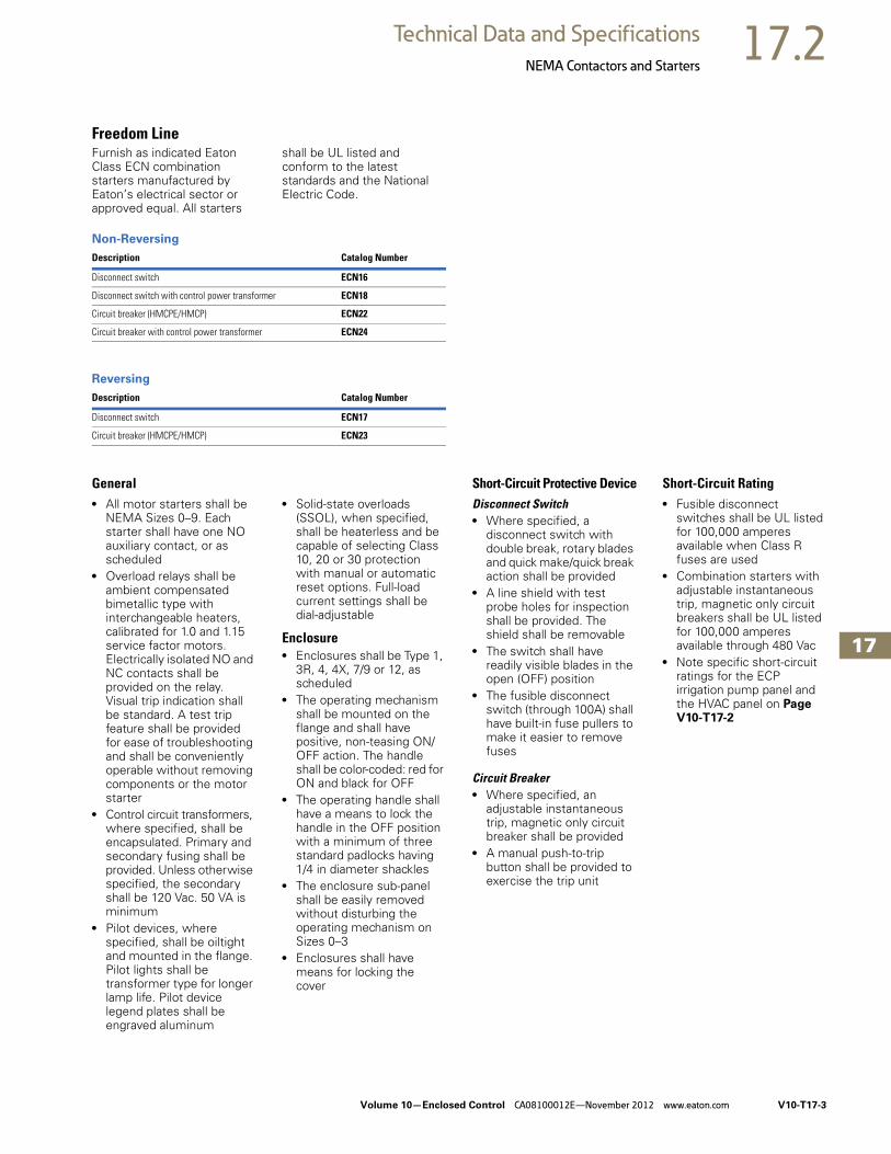
17.2Technical Data and Specifications
NEMA Contactors and Starters
Freedom LineFurnish as indicated Eaton Class ECN combination starters manufactured by Eaton’s electrical sector or approved equal. All starters
shall be UL listed and conform to the latest standards and the National Electric Code.
Non-Reversing
Reversing
General● All motor starters shall be
NEMA Sizes 0–9. Each starter shall have one NO auxiliary contact, or as scheduled
● Overload relays shall be ambient compensated bimetallic type with interchangeable heaters, calibrated for 1.0 and 1.15 service factor motors. Electrically isolated NO and NC contacts shall be provided on the relay. Visual trip indication shall be standard. A test trip feature shall be provided for ease of troubleshooting and shall be conveniently operable without removing components or the motor starter
● Control circuit transformers, where specified, shall be encapsulated. Primary and secondary fusing shall be provided. Unless otherwise specified, the secondary shall be 120 Vac. 50 VA is minimum
● Pilot devices, where specified, shall be oiltight and mounted in the flange. Pilot lights shall be transformer type for longer lamp life. Pilot device legend plates shall be engraved aluminum
● Solid-state overloads (SSOL), when specified, shall be heaterless and be capable of selecting Class 10, 20 or 30 protection with manual or automatic reset options. Full-load current settings shall be dial-adjustable
Enclosure● Enclosures shall be Type 1,
3R, 4, 4X, 7/9 or 12, as scheduled
● The operating mechanism shall be mounted on the flange and shall have positive, non-teasing ON/OFF action. The handle shall be color-coded: red for ON and black for OFF
● The operating handle shall have a means to lock the handle in the OFF position with a minimum of three standard padlocks having 1/4 in diameter shackles
● The enclosure sub-panel shall be easily removed without disturbing the operating mechanism on Sizes 0–3
● Enclosures shall have means for locking the cover
Short-Circuit Protective DeviceDisconnect Switch● Where specified, a
disconnect switch with double break, rotary blades and quick make/quick break action shall be provided
● A line shield with test probe holes for inspection shall be provided. The shield shall be removable
● The switch shall have readily visible blades in the open (OFF) position
● The fusible disconnect switch (through 100A) shall have built-in fuse pullers to make it easier to remove fuses
Circuit Breaker● Where specified, an
adjustable instantaneous trip, magnetic only circuit breaker shall be provided
● A manual push-to-trip button shall be provided to exercise the trip unit
Short-Circuit Rating● Fusible disconnect
switches shall be UL listed for 100,000 amperes available when Class R fuses are used
● Combination starters with adjustable instantaneous trip, magnetic only circuit breakers shall be UL listed for 100,000 amperes available through 480 Vac
● Note specific short-circuit ratings for the ECP irrigation pump panel and the HVAC panel on Page V10-T17-2
Description Catalog Number
Disconnect switch ECN16
Disconnect switch with control power transformer ECN18
Circuit breaker (HMCPE/HMCP) ECN22
Circuit breaker with control power transformer ECN24
Description Catalog Number
Disconnect switch ECN17
Circuit breaker (HMCPE/HMCP) ECN23

V10-T17-4 Volume 10—Enclosed Control CA08100012E—November 2012 www.eaton.com
17
17
17
17
17
17
17
17
17
17
17
17
17
17
17
17
17
17
17
17
17
17
17
17
17
17
17
17
17
17
17.2 Technical Data and Specifications
NEMA Contactors and Starters
Technical DataAll data is based on a standard contactor with no auxiliary devices and a 120 Vac or 24 Vdc magnet
coil. Coil data has a ±5% range depending on the application, therefore specific data may vary.
Coil Data Notes
Specifications—Sizes 00–3
P.U. Pickup time is the average time taken from closing of the coil circuit to main contact touch
D.O. Dropout time is the average time taken from opening of the coil circuit to main contact separation
Cold Coil data with a cold coil
Hot Coil data with a hot coil
Description
Contactor Catalog Number/SizeCN15ANEMA Size 00
CN15BNEMA Size 0
CN15DNEMA Size 1
CN15GNEMA Size 2
CN15KNEMA Size 3
Configuration
Number of poles 2, 3, 4 2, 3 2, 3, 4, 5 2, 3, 4, 5 2, 3
Auxiliary contacts, standard Fourth pole NO (1) Side NO (1) Side NO (1) Side NO (1) Side NO (1)
Add-on auxiliary contacts Top (4) or side (4) Top (4) or side (3) Top (4) or side (3) Top (4) or side (3) Left side (4) or right side (3)
Frame size 45 mm 45 mm 65 mm 65 mm 90 mm
Maximum voltage rating 600 Vac 600 Vac 600 Vac 600 Vac 600 Vac
Continuous ampere ratings (I) 9A 18A 27A 45A 90A
Maximum Horsepower (hp)
Single-phase
115V 1/3 1 2 3 7-1/2
230V 1 2 3 7-1/2 15
Three-phase
200V 1-1/2 3 7-1/2 10 25
230V 1-1/2 3 7-1/2 15 30
460V 2 5 10 25 50
575V 2 5 10 25 50
AC Magnet Coil Data
Pickup volts—cold 74% 74% 74% 74% 72%
Pickup volts—hot 78% 78% 78% 78% 76%
Pickup voltamperes 80 100 230 230 390
Pickup watts 49 65 95 95 112
Sealed voltamperes 7.5 10 28 28 49.8
Sealed watts 2.4 3.1 7.8 7.8 13
Dropout volts—cold 45% 45% 49% 49% 50%
Dropout volts—hot 46% 46% 50% 50% 52%
Maximum operation rate—ops/hour 12,000 12,000 12,000 12,000 7,200
Pickup time (ms) 12 12 20 20 14
Dropout time (ms) 12 12 14 14 11
Coil operating range % of rated voltage –15% to +10% –15% to +10% –15% to +10% –15% to +10% –15% to +10%
DC magnet coil data For DC magnet coils (and coil data), see Accessories, Tab14.
Operating temperature –20° to 65°C –20° to 65°C –20° to 65°C –20° to 65°C –20° to 65°C
Maximum operating altitude (ft) 6000 6000 6000 6000 6000
Mechanical life 20,000,000 20,000,000 10,000,000 10,000,000 6,000,000

Volume 10—Enclosed Control CA08100012E—November 2012 www.eaton.com V10-T17-5
17
17
17
17
17
17
17
17
17
17
17
17
17
17
17
17
17
17
17
17
17
17
17
17
17
17
17
17
17
17
17.2Technical Data and Specifications
NEMA Contactors and Starters
Specifications—Sizes 00–3, continued
Specifications—Sizes 4–8
Description
Contactor Catalog Number/SizeCN15ANEMA Size 00
CN15BNEMA Size 0
CN15DNEMA Size 1
CN15GNEMA Size 2
CN15KNEMA Size 3
Electrical Life (480V/60 Hz)
AC-3 4,000,000 3,000,000 5,000,000 3,500,000 1,700,000
AC-4 90,000 85,000 200,000 62,000 80,000
Wire Range
Power terminals 12–16 stranded,12–14 solid Cu
8–16 stranded,10–14 solid Cu
8–14 stranded or solid Cu
2–14 (upper) and/or6–14 (lower)stranded or solid Cu
1/0–14 Cu
Control terminals 12–16 stranded,12–14 solid Cu
12–16 stranded,12–14 solid Cu
12–16 stranded,12–14 solid Cu
12–16 stranded,12–14 solid Cu
12–16 stranded,12–14 solid Cu
Power terminal torque line and load—lb-in
7 15 20 40 (14–8 AWG)45 (6–4 AWG)50 (3 AWG)
35 (14–10 AWG)40 (8 AWG)45 (6–4 AWG)50 (3–1/0 AWG)
Auxiliary contact rating A600, P300 A600, P300 A600, P300 A600, P300 A600, P300
Description
Contactor Catalog Number/SizeCN15NNEMA Size 4
CN15SNEMA Size 5
CN15TNEMA Size 6
CN15UNEMA Size 7
CN15VNEMA Size 8
Configuration
Number of poles 2, 3 2, 3 3 3 3
Auxiliary contacts, standard Side NO (1) Side NO (1) Top left 2NO/2NC (1) Top left 2NO/2NC (1) Side 2NO/NC (1)
Add-on auxiliary contacts Left side (3) or right side (4)
Left side (3) or right side (4)
Top right 2NO/2NC (1) Top right 2NO/2NC (1) NO/NC (2)
Frame size 180 mm 180 mm 280 mm 280 mm 334 mm
Maximum voltage rating 600 Vac 600 Vac 600 Vac 600 Vac 600 Vac
Continuous ampere ratings (I) 135A 270A 540A 810A 1215A
Maximum Horsepower (hp)
Single-phase
115V — — — — —
230V — — — — —
Three-phase
200V 40 75 150 200 400
230V 50 100 200 300 450
460V 100 200 400 600 900
575V 100 200 400 600 900
AC Magnet Coil Data
Pickup volts—cold 72.5% 75% 75% 75% 75%
Pickup volts—hot 76% 77% 75% 75% 75%
Pickup voltamperes 1158 1158 1600 1600 2450
Pickup watts 240 240 1345 1345 2060
Sealed voltamperes 100 100 25 25 75
Sealed watts 27.2 27.2 22 22 60

V10-T17-6 Volume 10—Enclosed Control CA08100012E—November 2012 www.eaton.com
17
17
17
17
17
17
17
17
17
17
17
17
17
17
17
17
17
17
17
17
17
17
17
17
17
17
17
17
17
17
17.2 Technical Data and Specifications
NEMA Contactors and Starters
Specifications—Sizes 4–8, continued
Note1 20–30% of rated coil voltage.
Description
Contactor Catalog Number/SizeCN15NNEMA Size 4
CN15SNEMA Size 5
CN15TNEMA Size 6
CN15UNEMA Size 7
CN15VNEMA Size 8
AC Magnet Coil Data, continued
Dropout volts—cold 54% 63% 1 1 1
Dropout volts—hot 56% 64% 1 1 1
Maximum operation rate—ops/hour 2,400 2,400 N/A N/A N/A
Pickup time (ms) 28 25 105 105 70
Dropout time (ms) 14 13 200 200 50
Coil operating range % of rated voltage –15% to +10% –15% to +10% –15% to +10% –15% to +10% –15% to +10%
DC magnet coil data For DC magnet coils (and coil data), see Accessories, Tab 15
Operating temperature –20° to 65°C –20° to 65°C –20° to 65°C –20° to 65°C –20° to 65°C
Maximum operating altitude (ft) 6,000 6,000 6,000 6,000 6,000
Mechanical life 5,000,000 5,000,000 5,000,000 5,000,000 5,000,000
Electrical Life (480V/60 Hz)
AC-3 800,000 500,000 590,000 450,000 420,000
AC-4 70,000 34,000 7,400 5,000 4,200
Wire Range
Power terminals Open—3/0–8 Cu, Enclosed—250 kcmil–6 Cu/Al
750 kcmil—2 or (2) 250 kcmil–3/0 Cu/Al
(2) 750 kcmil–3/0 Cu/Al (3) 750 kcmil– 3/0 Cu/Al (4) 750 kcmil–1/0 Cu/Al
Control terminals 12–16 stranded, 12–14 solid Cu
12–16 stranded, 12–14 solid Cu
12–16 stranded, 12–14 solid Cu
12–16 stranded, 12–14 solid Cu
12–16 stranded, 12–14 solid Cu
Power terminal torqueline and load—lb-in
200 550 550 550 500
Auxiliary contact rating A600, P300 A600, P300 A600, P300 A600, P300 A600, P300

Volume 10—Enclosed Control CA08100012E—November 2012 www.eaton.com V10-T17-7
17
17
17
17
17
17
17
17
17
17
17
17
17
17
17
17
17
17
17
17
17
17
17
17
17
17
17
17
17
17
17.2Technical Data and Specifications
NEMA Contactors and Starters
Electrical Life—AC-3 and AC-4 Utilization Categories
Life Load CurvesEaton’s Freedom Series NEMA contactors have been designed and manufactured for superior life performance in any worldwide application. All testing has been based on requirements as found in NEMA and UL standards and conducted by Eaton. Actual application life may vary depending on environmental conditions and application duty cycle.
Utilization CategoriesAC-1—Non-inductive or slightly inductive loads, such as resistance furnaces and heating.
AC-2—Starting of slip-ring motors.
AC-3—Squirrel cage motors; starting, switching off motors during running.
AC-4—Squirrel cage motors; starting, plugging, inching or jogging.
Note: AC-3 tests are conducted at rated device currents and AC-4 tests are conducted at six times rated device currents. All tests have been run at 460V, 60 Hz.
Contactor Choice● Decide what utilization
category your application is and choose the appropriate curve
● Locate the intersection of the life-load curve of the appropriate contactor with the applications operational current (Ie), as found on the horizontal axis
● Read the estimated contact life along the vertical axis in number of operational cycles
AC-3 and AC-4 Utilization Categories
NEMA AC-3 Load Life, Sizes 00–5, 480V 60 Hz
100,000,000
10,000,000
1,000,000
100,0009
1 10Break Amperes
100 1000
18 27 45 90 135 270
Siz
e 0
0
Siz
e 0
Siz
e 1
Siz
e 2
Siz
e 3
Siz
e 4
Siz
e 5
Op
era
tio
ns
Op
era
tio
ns
NEMA AC-4 Load Life, Sizes 00–5, 480V 60 Hz
100,000,000
Siz
e 0
0
Siz
e 0
Siz
e 1
Siz
e 2
Siz
e 3
Siz
e 4
Siz
e 5
10,000,000
1,000,000
100,000
10,00010854
1 10Break Amperes
100 1000 10,000153 270 540 822 1620
V10-T17-8 Volume 10—Enclosed Control CA08100012E—November 2012 www.eaton.com
17
17
17
17
17
17
17
17
17
17
17
17
17
17
17
17
17
17
17
17
17
17
17
17
17
17
17
17
17
17
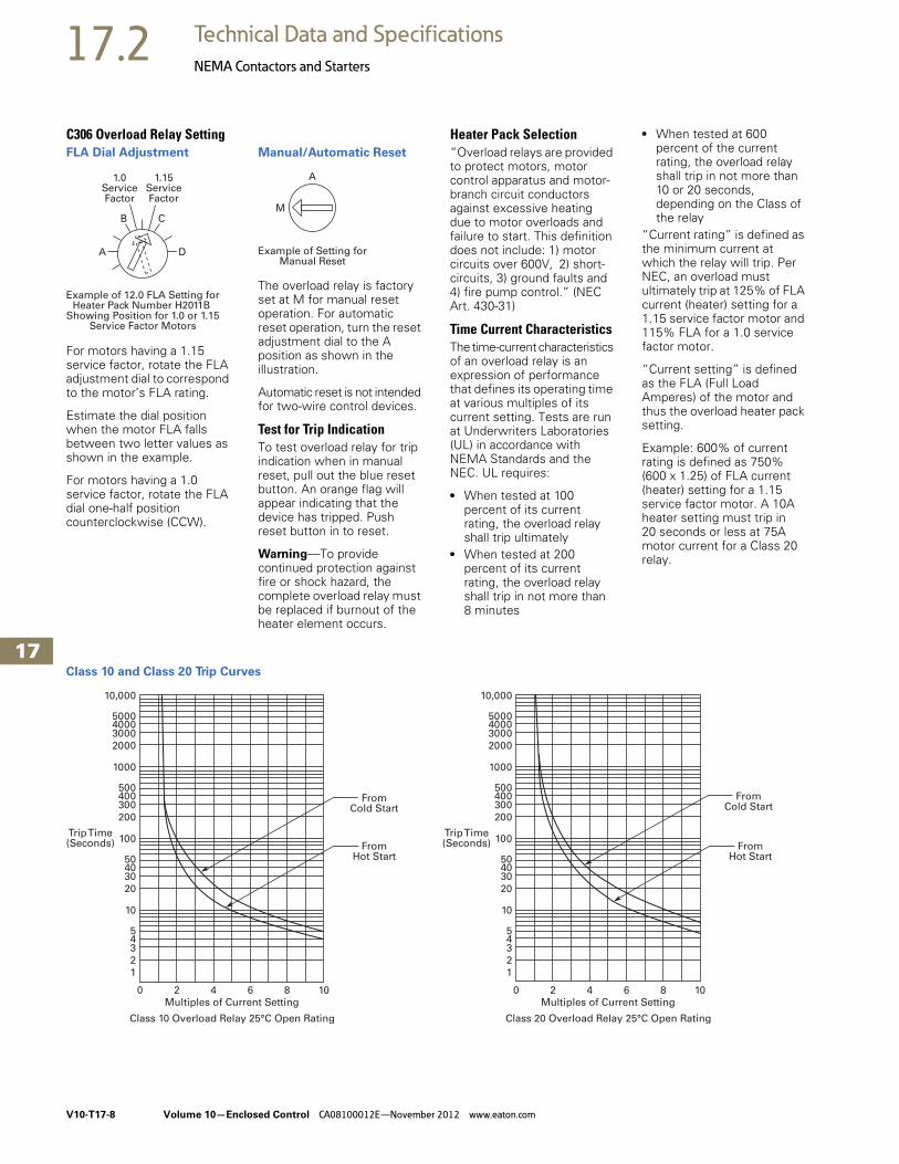
17.2 Technical Data and Specifications
NEMA Contactors and Starters
C306 Overload Relay SettingFLA Dial Adjustment
For motors having a 1.15 service factor, rotate the FLA adjustment dial to correspond to the motor’s FLA rating.
Estimate the dial position when the motor FLA falls between two letter values as shown in the example.
For motors having a 1.0 service factor, rotate the FLA dial one-half position counterclockwise (CCW).
Manual/Automatic Reset
The overload relay is factory set at M for manual reset operation. For automatic reset operation, turn the reset adjustment dial to the A position as shown in the illustration.
Automatic reset is not intended for two-wire control devices.
Test for Trip IndicationTo test overload relay for trip indication when in manual reset, pull out the blue reset button. An orange flag will appear indicating that the device has tripped. Push reset button in to reset.
Warning—To provide continued protection against fire or shock hazard, the complete overload relay must be replaced if burnout of the heater element occurs.
Heater Pack Selection“Overload relays are provided to protect motors, motor control apparatus and motor-branch circuit conductors against excessive heating due to motor overloads and failure to start. This definition does not include: 1) motor circuits over 600V, 2) short-circuits, 3) ground faults and 4) fire pump control.” (NEC Art. 430-31)
Time Current CharacteristicsThe time-current characteristics of an overload relay is an expression of performance that defines its operating time at various multiples of its current setting. Tests are run at Underwriters Laboratories (UL) in accordance with NEMA Standards and the NEC. UL requires:
● When tested at 100 percent of its current rating, the overload relay shall trip ultimately
● When tested at 200 percent of its current rating, the overload relay shall trip in not more than 8 minutes
● When tested at 600 percent of the current rating, the overload relay shall trip in not more than 10 or 20 seconds, depending on the Class of the relay
“Current rating” is defined as the minimum current at which the relay will trip. Per NEC, an overload must ultimately trip at 125% of FLA current (heater) setting for a 1.15 service factor motor and 115% FLA for a 1.0 service factor motor.
“Current setting” is defined as the FLA (Full Load Amperes) of the motor and thus the overload heater pack setting.
Example: 600% of current rating is defined as 750% (600 x 1.25) of FLA current (heater) setting for a 1.15 service factor motor. A 10A heater setting must trip in 20 seconds or less at 75A motor current for a Class 20 relay.
Class 10 and Class 20 Trip Curves
1.0ServiceFactor
1.15ServiceFactor
A
B C
D
Example of 12.0 FLA Setting forHeater Pack Number H2011B
Showing Position for 1.0 or 1.15Service Factor Motors
A
M
Example of Setting forManual Reset
0
1
2
345
10
20
304050
100
200
300400500
1000
2000
300040005000
10,000
2 4 6 8 10
FromHot Start
FromCold Start
Multiples of Current Setting
Trip Time(Seconds)
Class 10 Overload Relay 25°C Open Rating
0
1
2
345
10
20
304050
100
200
300400500
1000
2000
300040005000
10,000
2 4 6 8 10
FromHot Start
FromCold Start
Multiples of Current Setting
Trip Time(Seconds)
Class 20 Overload Relay 25°C Open Rating

Volume 10—Enclosed Control CA08100012E—November 2012 www.eaton.com V10-T17-9
17
17
17
17
17
17
17
17
17
17
17
17
17
17
17
17
17
17
17
17
17
17
17
17
17
17
17
17
17
17
17.2Technical Data and Specifications
NEMA Contactors and Starters
Relays
Wire (75°C) Sizes—AWG or kcmil—NEMA Sizes 00–2—Open
Wire (75°C) Sizes—AWG or kcmil—NEMA Sizes 3–8—Open
Power Terminal Torque Line and Load Terminals
Plugging and Jogging Service Horsepower Ratings 3
Overload Relay UL/CSA Contact Ratings Control Circuit 2
Notes1 Two compartment box lug. 2 DC ratings cover Freedom Series coils only.3 Maximum horsepower where operation is interrupted more than 5 times per minute or more
than 10 times in a 10 minute period. NEMA standard ICS 2-1993 table 2-4-3.
NEMA Size Cu Only
Power Terminals—Line
00 12–16 stranded, 12–14 solid
0 8–16 stranded, 10–14 solid
1 8–14 stranded or solid
2 3–14 (upper) and/or 6–14 (lower) stranded or solid 1
Power Terminals—Load—Cu Only (Stranded or Solid)
Terminal Wire SizeCatalogNumber
32A 14–6 AWG C306DN3B
75A 14–2 AWG C306GN3B
Control Terminals—Cu Only
12–16 AWG stranded, 12–14 AWG solid
NEMA Size Wire Size
Power Terminals—Line and Load
3 1/0–14 Cu/Al
4 Open—3/0–8 Cu
Enclosed—250 kcmil—6 Cu/Al
5 750 kcmil—2 or (2) 250 kcmil—3/0 Cu/Al
6–7 (2) 750 kcmil—3/0 Cu/Al
8 (2) 750 kcmil—1/0 Cu/Al
Control Terminals—Cu Only
12–16 AWG stranded, 12–14 AWG solid
Terminal Torque in lb-in Catalog Number
32A 20 C306DT3B
75A 35 (14–10 AWG) C306GT3B
40 (8 AWG)
45 (6–4 AWG)
50 (3–2 AWG)
105A 120 (3/16) C306KN3(Socket head screw)200 (1/4)
250 (5/16)
144A 120 (3/16) C306NN3(Socket head screw)200 (1/4)
250 (5/16)
35 (14–10 AWG) C306NN3(Slotted head screw)40 (8 AWG)
45 (6–4 AWG)
50 (3–1/0 AWG)
NEMA Size 200V 230V 460V 575V
00 — 1/2 1/2 1/2
0 1-1/2 1-1/2 2 2
1 3 3 5 5
2 7-1/2 10 15 15
3 15 20 30 30
4 25 30 60 60
5 60 75 150 150
6 125 150 300 300
AC Volts 120V 240V 480V 600V
NC Contact B600
Make and break amps 30 15 7.5 6
Break amps 3 1.5 0.75 0.6
Continuous amps 5 5 5 5
NO Contact C600
Make and break amps 15 7.5 3.375 3
Break amps 1.5 0.75 0.375 0.3
Continuous amps 2.5 2.5 2.5 2.5

V10-T17-10 Volume 10—Enclosed Control CA08100012E—November 2012 www.eaton.com
17
17
17
17
17
17
17
17
17
17
17
17
17
17
17
17
17
17
17
17
17
17
17
17
17
17
17
17
17
17
17.2 Technical Data and Specifications
NEMA Contactors and Starters
Dimensions and WeightsApproximate Dimensions in Inches (mm)
C306 Standalone Overload Relays
AmpereSize
WideA
HighB
DeepC
Mounting Ship. Wt.Lbs (kg)D E F (Slot) G (Hole)
32A 1.77 (45.0) 4.13 (104.9) 3.69 (93.7) 1.36 (34.5) 3.74 (95.0) 0.18 x 0.30 (4.6 x 7.6) 0.18 (4.6) dia. 0.8 (0.4)
75A 2.54 (64.5) 4.69 (119.1) 3.74 (95.0) 2.00 (50.8) 3.45 (87.6) 0.22 x 0.26 (5.6 x 6.6) 0.21 (5.3) dia. 1.4 (0.6)
105 and 144A 4.00 (101.6) 7.17 (182.1) 4.91 (124.7) 3.00 (76.2) 6.62 (168.1) — — 4.0 (1.8)
D
A C
C
EB
EB
ADF
32A and 75A SizesC306DT3B and C306GT3B
105A and 144A SizesC306KN3 and C306NN3
G
Mtg. Holes for (3)1/4-20 Screws

Volume 10—Enclosed Control CA08100012E—November 2012 www.eaton.com V10-T17-11
17
17
17
17
17
17
17
17
17
17
17
17
17
17
17
17
17
17
17
17
17
17
17
17
17
17
17
17
17
17
17.3Technical Data and Specifications
IEC Contactors and Starters
XT LineFurnish as indicated Eaton Class ECX combination starters manufactured by Eaton’s electrical sector or approved equal. All starters
shall be UL listed and conform to the latest IEC Standards and the National Electric Code.
Non-Reversing
Reversing
General● All motor starters shall be
IEC Sizes A–N (60 hp at 460V). Each starter shall have one NO auxiliary contact, or as scheduled
● Overload relays shall be ambient compensated bimetallic type with interchangeable heaters, calibrated for 1.0 and 1.15 service factor motors. Electrically isolated NO and NC contacts shall be provided on the relay. Visual trip indication shall be standard. A test trip feature shall be provided for ease of troubleshooting and shall be conveniently operable without removing components or the motor starter. Overload relays may also be solid-state
● Control circuit transformers, where specified, shall be encapsulated. Primary and secondary fusing shall be provided. Unless otherwise specified, the secondary shall be 120 Vac. 50 VA is minimum
● Pilot devices, where specified, shall be oiltight and mounted in the flange. Pilot lights shall be transformer type for longer lamp life. Pilot device legend plates shall be engraved aluminum
Enclosure● Enclosures shall be Type 1,
3R, 4, 4X, 7/9 or 12, as scheduled
● The operating mechanism shall be mounted on the flange and shall have positive, non-teasing ON/OFF action. The handle shall be color-coded: red for ON and black for OFF
● The operating handle shall have a means to lock the handle in the OFF position with a minimum of three standard padlocks having 1/4 in diameter shackles
● The enclosure sub-panel shall be easily removed without disturbing the operating mechanism
● Enclosures shall have means for locking the cover
Short-Circuit Protective DeviceDisconnect Switch● Where specified, a
disconnect switch with double break, rotary blades and quick make/quick break action shall be provided
● A line shield with test probe holes for inspection shall be provided. The shield shall be removable
● The switch shall have readily visible blades in the open (OFF) position
● The fusible disconnect switch (through 100A) shall have built-in fuse pullers to make it easier to remove fuses
Circuit Breaker● Where specified, an
adjustable instantaneous trip, magnetic only circuit breaker shall be provided
● A manual push-to-trip button shall be provided to exercise the trip unit
Short-Circuit Rating● Fusible disconnect switches
shall be UL listed for 100,000 amperes available when Class R fuses are used
● Combination starters with adjustable instantaneous trip, magnetic only circuit breakers shall be UL listed for 100,000 amperes available through 480 Vac
Description Catalog Number
Disconnect switch ECX19
Circuit breaker (HMCP) ECX25
Description Catalog Number
Disconnect switch ECX20
Circuit breaker (HMCP) ECX26

V10-T17-12 Volume 10—Enclosed Control CA08100012E—November 2012 www.eaton.com
17
17
17
17
17
17
17
17
17
17
17
17
17
17
17
17
17
17
17
17
17
17
17
17
17
17
17
17
17
17
17.3 Technical Data and Specifications
IEC Contactors and Starters
Technical Data
Instructional Leaflets
Instructional Leaflets
Publication Number Description
Pub51210 7–15A, B Frame XTCE, XTCEC and XTCF Contactors and Accessories (inside of packaging)
Pub51211 18–32A, C Frame XTCE and XTCEC Contactors and Accessories (inside of packaging)
Pub51221 XTOB, D Frame Overload Relays (inside of packaging)
Pub51222 XTOB, B–C Frame Overload Relays (inside of packaging)
Pub51237 7–12A, B Frame XTCE Contactors and Auxiliary Contacts
Pub51232 18–32A, C Frame XTCE Contactors and Auxiliary Contacts
Pub51216 40–65A, D Frame XTCE Contactors and Auxiliary Contacts
Pub51203 185–500A, L–M Frame XTCE Contactors and Auxiliary Contacts
Pub51215 S-Series 185–500A, L–M Frame XTCE Contactors and Auxiliary Contacts
Pub51204 580–1000A, N Frame XTCE Contactors and Auxiliary Contacts
Pub51209 1400–2000A, P–R Frame XTCE Contactors and Auxiliary Contacts
Pub51213 7–150A, B–G Frame XTAE non-reversing and XTAR Reversing Starters
Pub51217 XTCEXFA and XTCEXSA Front and Side-mount Auxiliary Contacts from 40–150A, D–G Frame XTCE Contactors
Pub51212 XTCEXML Mechanical Interlock for 7–150A, B–G Frame XTCE Contactors
Pub51214 XTCEXRL Reversing Link Kits for 18–32A, C Frame XTCE Contactors
Pub51218 XTCEXTL Lug Kits for 500–820A, M–N Frame XTCE Contactors
Pub51219 XTCEXRLB and XTCEXSDLB Reversing and Star-Delta (Wye-Delta) Link Kits for 7–12A, B Frame XTCE Contactors
Pub51205 Accessories for 185–500A, L–M Frame XTCE Contactors
Pub51207 Replacement DC Coils
Pub51213 Renewal Parts—Coils for 18–32A, C Frame XTCE Contactors
Pub51186 Renewal Parts—Coils for 40–65A, D Frame XTCE Contactors

Volume 10—Enclosed Control CA08100012E—November 2012 www.eaton.com V10-T17-13
17
17
17
17
17
17
17
17
17
17
17
17
17
17
17
17
17
17
17
17
17
17
17
17
17
17
17
17
17
17
17.3Technical Data and Specifications
IEC Contactors and Starters
Coil Data
Frame B–D
Coil Data—Frame B–D
Notes1 0.7–1.3 without additional auxiliary contact modules and ambient temperature +40°C (104°F).2 Coil suffix TD: Umin 24 Vdc/Umax 27 Vdc.
Coil suffix WD: Umin 48 Vdc/Umax 60 Vdc.Coil suffix AD: Umin 110 Vdc/Umax 130 Vdc.Coil suffix BD: Umin 200 Vdc/Umax 240 Vdc.Example:Uc = 0.7 x Umin—1.2 x UmaxUc = 0.7 x 24V—1.2 x 27 Vdc
Description XTCE007B XTCE009BXTCE012B,XTCF020B XTCE015B XTCE018C XTCE025C XTCE032C XTCE040D XTCE050D XTCE065D
Voltage Tolerance
Pickup (x Uc)AC operated 0.8–1.1 0.8–1.1 0.8–1.1 0.8–1.1 0.8–1.1 0.8–1.1 0.8–1.1 0.8–1.1 0.8–1.1 0.8–1.1
DC operated 0.8–1.1 1 0.8–1.1 1 0.8–1.1 1 0.8–1.1 1 0.7–1.2 2 0.7–1.2 2 0.7–1.2 2 0.7–1.2 2 0.7–1.2 2 0.7–1.2 2
Dropout (x Uc)AC operated 0.3–0.6 0.3–0.6 0.3–0.6 0.3–0.6 0.3–0.6 0.3–0.6 0.3–0.6 0.3–0.6 0.3–0.6 0.3–0.6
DC operated 0.15–0.6 0.15–0.6 0.15–0.6 0.15–0.6 0.15–0.6 0.15–0.6 0.15–0.6 0.15–0.6 0.15–0.6 0.15–0.6
Power Consumption of the Coil at Cold State and 1.0 x Uc
AC operatedSingle-voltage coil 50 Hz
Pickup VA 24 24 24 24 52 52 52 149 149 149
Pickup W 19 19 19 19 40 40 40 80 80 80
Sealing VA 3.4 3.4 3.4 3.4 7.1 7.1 7.1 16 16 16
Sealing W 1.2 1.2 1.2 1.2 2.1 2.1 2.1 4.3 4.3 4.3
Single-voltage coil 60 HzPickup VA 30 30 30 30 67 67 67 178 178 178
Pickup W 23 23 23 23 50 50 50 117 117 117
Sealing VA 4.4 4.4 4.4 4.4 8.7 8.7 8.7 19 19 19
Sealing W 1.4 1.4 1.4 1.4 2.6 2.6 2.6 5.3 5.3 5.3
50/60 HzPickup VA 27 27 27 27 62 62 62 168 168 168
25 25 25 25 58 58 58 154 154 154
Pickup W 22 22 22 22 48 48 48 120 120 120
21 21 21 21 43 43 43 43 43 43
Sealing VA 4.2 4.2 4.2 4.2 9.1 9.1 9.1 22 22 22
3.3 3.3 3.3 3.3 6.5 6.5 6.5 14 14 14
Sealing W 1.4 1.4 1.4 1.4 2.5 2.5 2.5 5.3 5.3 5.3
1.2 1.2 1.2 1.2 2 2 2 4.3 4.3 4.3
DC operatedPickup W 3 3 4.5 4.5 12 at 24V 12 at 24V 12 at 24V 24 at 24V 24 at 24V 24 at 24V
Sealing W 3 3 4.5 4.5 0.5 at 24V 0.5 at 24V 0.5 at 24V 0.5 at 24V 0.5 at 24V 0.5 at 24V
Duty factor (%DF) 100 100 100 100 100 100 100 100 100 100
Switching Time at 100% Uc (Approximate Values)
Main contactAC operated
Closing delay (ms) <21 <21 <21 <21 <22 <22 <22 <18 <18 <18
Opening delay (ms) <18 <18 <18 <18 <14 <14 <14 <13 <13 <13
DC operatedClosing delay (ms) <31 <31 <31 <31 <47 <47 <47 <54 <54 <54
Opening delay (ms) <12 <12 <12 <12 <30 <30 <30 <24 <24 <24
Arcing time (ms) 10 10 10 10 10 10 10 10 10 10
Electromagnetic Compatibility (EMC)
Emitted interference To EN-60947-1
Noise immunity To EN-60947-1
V10-T17-14 Volume 10—Enclosed Control CA08100012E—November 2012 www.eaton.com
17
17
17
17
17
17
17
17
17
17
17
17
17
17
17
17
17
17
17
17
17
17
17
17
17
17
17
17
17
17
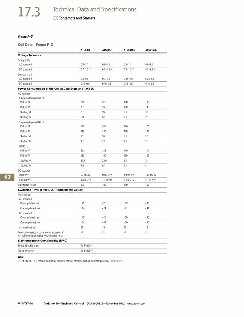
17.3 Technical Data and Specifications
IEC Contactors and Starters
Frame F–G
Coil Data—Frame F–G
Note1 At 24V: 0.7–1.3 without additional auxiliary contact modules and ambient temperature +40°C (104°F).
XTCE80F XTCE95F XTCE115G XTCE150G
Voltage Tolerance
Pickup (x Uc)
AC operated 0.8–1.1 0.8–1.1 0.8–1.1 0.8–1.1
DC operated 0.7–1.2 1 0.7–1.2 1 0.7–1.2 1 0.7–1.2 1
Dropout (x Uc)
AC operated 0.3–0.6 0.3–0.6 0.25–0.6 0.25–0.6
DC operated 0.15–0.6 0.15–0.6 0.15–0.6 0.15–0.6
Power Consumption of the Coil at Cold State and 1.0 x Uc
AC operated
Single-voltage coil 50 Hz
Pickup VA 310 310 180 180
Pickup W 165 165 130 130
Sealing VA 26 26 3.1 3.1
Sealing W 5.8 5.8 2.1 2.1
Single-voltage coil 60 Hz
Pickup VA 345 345 170 170
Pickup W 190 190 130 130
Sealing VA 30 30 3.1 3.1
Sealing W 7.1 7.1 2.1 2.1
50/60 Hz
Pickup VA 372 328 170 170
Pickup W 190 190 130 130
Sealing VA 37.1 22.6 3.1 3.1
Sealing W 7.5 6.1 2.1 2.1
DC operated
Pickup W 90 at 24V 90 at 24V 149 at 24V 149 at 24V
Sealing W 1.3 at 24V 1.3 at 24V 2.1 at 24V 2.1 at 24V
Duty factor (%DF) 100 100 100 100
Switching Time at 100% Uc (Approximate Values)
Main contact
AC operated
Closing delay (ms) <20 <20 <33 <33
Opening delay (ms) <14 <14 <41 <41
DC operated
Closing delay (ms) <45 <45 <35 <35
Opening delay (ms) <34 <34 <30 <30
Arcing time (ms) 15 15 15 15
Permissible residual current with actuation ofA1–A2 by the electronics (with 0 signal) (mA)
<1 <1 <1 <1
Electromagnetic Compatibility (EMC)
Emitted interference To EN60947-1
Noise immunity To EN60947-1

Volume 10—Enclosed Control CA08100012E—November 2012 www.eaton.com V10-T17-15
17
17
17
17
17
17
17
17
17
17
17
17
17
17
17
17
17
17
17
17
17
17
17
17
17
17
17
17
17
17
17.3Technical Data and Specifications
IEC Contactors and Starters
Frame L–R
Coil Data—Frame L–R
Note1 Control transformer with Uk <6%.
Description XTCE185LXTCE225L, XTCE250L
XTCE300M, XTCE400M XTCE500M
Voltage Tolerance
Pickup (x Uc)XTCE185L–XTCEC20R 0.7 x Ucmin—1.15 x Ucmax
XTCS185L–XTCS500M 0.85 x Ucmin—1.1 x Ucmax
Dropout (x Uc)XTCE185L–XTCEC20R 0.2 x Ucmin—0.6 x Ucmax
XTCS185L–XTCS500M 0.2 x Ucmin—0.4 x Ucmax
Power Consumption of the Coil at Cold State and 1.0 x Uc
XTCE185L–XTCEC20RPickup VA 250 1 250 1 450 1 450 1
Pickup W 200 200 350 350
Sealing VA 4.3 4.3 4.3 4.3
Sealing W 3.3 3.3 3.3 3.3
XTCS185L–XTCS500MPickup VA 360 360 715 715
Pickup W 325 325 645 645
Sealing VA 4.3 4.3 4.3 4.3
Sealing W 3.3 3.3 3.3 3.3
Duty Factor (%DF) 100 100 100 100
Switching Time at 100% Main Contact Uc (Approximate Values)
XTCE185L–XTCEC20RClosing delay (ms)
Opening delay (ms) <100 <100 <80 <80
XTCS185L–XTCS500M <80 <80 <80 <80Closing delay (ms) <50 <50 <50 <50
Opening delay (ms) <40 <40 <40 <40
Reaction in Threshold and Sealing State Transition Range (XTCE185L–XTCEC20R)
Voltage interruptions(0–0.2 x Ucmin) <10 ms Time is bridged successfully
(0–0.2 x Ucmin) >10 ms Dropout of the contactor
Voltage dips(0.2–0.6 x Ucmin) <12 ms Time is bridged successfully
(0.2–0.6 x Ucmin) >12 ms Dropout of the contactor
(0.6–0.7 x Ucmin) Contactor remains switched on
Excess voltage(1.15–1.3 x Ucmax) Contactor remains switched on
(>1.3 x Ucmax) <3s Contactor remains switched on
(>1.3 x Ucmax) >3s Dropout of the contactor
Pickup phase(0–0.7 x Ucmin) Contactor does not switch on
(0.7 x Ucmin –1.15 x Ucmax) Contactor switches on with certainty
(>1.15 x Ucmax) Contactor switches on with certainty
Permissible contact resistance (of the external command device with actuation of A11), ohms
<500 <500 <500 <500
Permissible residual current (with actuation of A11 by the electronics with 0 signal)
<1 <1 <1 <1
SPS signal level (A3–A4) to IEC/EN 61131-2 (Type 2)High 15V 15V 15V 15V
Low 5V 5V 5V 5V
Electromagnetic compatibility (EMC) This product is designed for operation in industrial environments. Usage in domestic areas can cause radio frequency interference (RFI). Noise suppression measures must be provided for the additional interference.

V10-T17-16 Volume 10—Enclosed Control CA08100012E—November 2012 www.eaton.com
17
17
17
17
17
17
17
17
17
17
17
17
17
17
17
17
17
17
17
17
17
17
17
17
17
17
17
17
17
17
17.3 Technical Data and Specifications
IEC Contactors and Starters
Coil Data—Frame L–R, continued
Note1 Control transformer with Uk <7%.
Description XTCE580NXTCE750N, XTCE820N XTCEC10N XTCEC14P XTCEC20R
Voltage Tolerance
Pickup (x Uc)XTCE185L–XTCEC20R 0.7 x Ucmin—1.15 x Ucmax
XTCS185L–XTCS500M 0.85 x Ucmin—1.1 x Ucmax
Dropout (x Uc)
XTCE185L–XTCEC20R 0.2 x Ucmin—0.6 x Ucmax
XTCS185L–XTCS500M 0.2 x Ucmin—0.4 x Ucmax
Power Consumption of the Coil at Cold State and 1.0 x Uc
XTCE185L–XTCEC20RPickup VA 800 1 800 1 800 1 800 1 1600 1
Pickup W 700 700 700 700 1400
Sealing VA 7.5 7.5 7.5 7.5 7.5
Sealing W 6.5 6.5 6.5 6.5 6.5
XTCS185L–XTCS500MPickup VA — — — — —
Pickup W — — — — —
Sealing VA — — — — —
Sealing W — — — — —
Duty Factor (%DF) 100 100 100 100 100
Switching Time at 100% Main Contact Uc (Approximate Values)
XTCE185L–XTCEC20RClosing delay (ms) <70 <70 <70 <70 <70
Opening delay (ms) <70 <70 <70 <70 <70
XTCS185L–XTCS500M
Closing delay (ms) — — — — —
Opening delay (ms) — — — — —
Reaction in Threshold and Sealing State Transition Range (XTCE185L–XTCEC20R)
Voltage interruptions(0–0.2 x Ucmin) <10 ms Time is bridged successfully
(0–0.2 x Ucmin) >10 ms Dropout of the contactor
Voltage dips(0.2–0.6 x Ucmin) <12 ms Time is bridged successfully
(0.6–0.7 x Ucmin) Dropout of the contactor
(0.6–0.7 x Ucmin) Contactor remains switched on
Excess voltage (1.15–1.3 x Ucmax) Contactor remains switched on
(>1.3 x Ucmax) <3s Contactor remains switched on
(>1.3 x Ucmax) >3s Dropout of the contactor
Pickup phase(0–0.7 x Ucmin) Contactor does not switch on
(0.7 x Ucmin –1.15 x Ucmax) Contactor switches on with certainty
(>1.15 x Ucmax) Contactor switches on with certainty
Permissible contact resistance (of the external command device with actuation of A11), ohms
<500 <500 <500 <500 <500
Permissible residual current (with actuation of A11 by the electronics with 0 signal)
<1 <1 <1 <1 <1
SPS signal level (A3–A4) to IEC/EN 61131-2 (Type 2)High 15V 15V 15V 15V 15V
Low 5V 5V 5V 5V 5V
Electromagnetic compatibility (EMC) This product is designed for operation in industrial environments. Usage in domestic areas can cause radio frequency interference (RFI). Noise suppression measures must be provided for the additional interference.

Volume 10—Enclosed Control CA08100012E—November 2012 www.eaton.com V10-T17-17
17
17
17
17
17
17
17
17
17
17
17
17
17
17
17
17
17
17
17
17
17
17
17
17
17
17
17
17
17
17
17.3Technical Data and Specifications
IEC Contactors and Starters
Contactor Contact Travel DiagramsThe diagrams indicate the closing and travel of the contacts of the contactors and auxiliary contacts at no-load. Tolerances are not taken into consideration.
Contactor Contact Travel Diagrams
4.5
4.53.30
0 1.0 2.9
2.92.10
0 0.7 4.4
4.43.30
0 1.0
4.5
4.53.20
0 1.6 2.9
2.92.30
0 0.7 4.4
4.43.20
0 1.6
4.5
4.52.00
0 2.8 2.9
2.91.10
0 1.9 4.4
4.42.00
0 2.8
6.040
1.8
3.2
7.55.10 1180
7.5
7.55.7
3.9
0
0
11
11
9.20
0 7.4
6
63.20
0 1.6
7.55.40
7.53.80 11
11
7.30
0 8.9
6
62.00
0 2.8
7.5
7.55.45
3.6
0
0
11
11
8.950
0 7.1
7.54.950
7.54.10 11
11
7.60
0 8.45
XTCE 7–15A, XTCF—AC
Frame B
Frame C Frame D Frame F and G
XTCEXSAC11
XTCEXF...LC_
XTCE 15–32A
XTCEXSBLN11 XTCEXSBLN11
XTCEXS...N_
XTCEXF...G–
XTCEXF...LG_
XTCE 80–150A
XTCEXF...LC_
XTCEXSAC11
XTCE 12–15A, XTCF—DC
XTCEXS...N_
XTCEXF...LG_
XTCEXF...G_
XTCE 40–65A
XTCEXF...LC_
XTCEXSAC11
XTCE 7–9A—DC
NO Contact
NC Contact
NO Contact
NC Contact
NO Contact
NC Contact
NO Contact
NC Contact
NO Contact
NC Contact
NO Contact
NC Contact
NO Contact
NC Contact
NO Contact
NC Contact
NO Contact
NC Contact
NO Contact
Auxiliary NC
Auxiliary NO
NO ContactNO Contact
NO Contact
NC Contact
NO Contact
NC ContactXTCEXSAC11, XTCEXF...C–
NO Contact
NC Contact
NO Contact
NC Contact
NO Contact
NC ContactXTCEXF...LC_
NO Contact
NC Contact
NO Contact
NC Contact
NO Contact
NC Contact
NO Contact
NC Contact
NO Contact
NC Contact

V10-T17-18 Volume 10—Enclosed Control CA08100012E—November 2012 www.eaton.com
17
17
17
17
17
17
17
17
17
17
17
17
17
17
17
17
17
17
17
17
17
17
17
17
17
17
17
17
17
17
17.3 Technical Data and Specifications
IEC Contactors and Starters
Auxiliary Contacts
Auxiliary Contacts Technical Data and Specifications
Notes1 Making and breaking conditions to DC-13, time L/R contact as stated.2 Conventional thermal current (Ith) of XTCEXSCC_ is 10A.3 See fuses overlay for time/current characteristic (on request).
DescriptionXTCE007B_– XTCE032C
XTCEXFAC_XTCEXFATC_
XTCEXFCC_XTCEXSCC_ XTCEXFAG_
XTCEXSBLN_XTCEXSBN_XTCEXSBNC_XTCEXSCN_XTCEXSCNC_
Interlocked opposing contacts with an auxiliary contact module (to IEC 60947-5 -1 Annex L)
— Yes Yes Yes Yes
Break contact (not late-break contact) suitable as a mirror contact (to IEC/EN 60947-4 -1 Annex F)
XTCE007B_–XTCE032C
XTCE007B_–XTCE032C
XTCE007B_–XTCE032C
XTCE040D_–XTCE065D_
XTCE040D_–XTCE065D_ XTCE185L_–XTCEC10N_
Rated impulse withstand voltage, (Uimp) Vac 6000 6000 6000 6000 6000
Overvoltage category/pollution degree III/3 III/3 III/3 III/3 III/3
Rated insulation voltage, (Ui) Vac 690 690 690 690 690
Rated operational voltage, (Ue) Vac 500 500 500 500 500
Safe isolation to VDE 0106 Part 101 and Part 101(A) in Vac
Between coil and auxiliary contacts 400 400 400 440 440
Between the auxiliary contacts 400 400 400 440 440
Rated operational current, leAC-15
230V 6A 6A 6A 6A 6A
380/415V 4A 3A 4A 4A 4A
500V 1.5A — 1.5A 1.5A 1.5A
DC-3 L/R <5 ms 1
24V 10A 10A 10A 10A 10A
60V 6A 6A 6A 6A 6A
110V 3A 3A 3A 3A 3A
220V 1A 1A 1A 1A 1A
Conventional thermal current, Ith 16A 16A 16A 2 10A 10A
Control circuit reliability (at Ue = 24 Vdc, Umin = 17 V, Imin = 5.4 mA)
<10-8, < one failure at 100 million operations
Component lifespan, operations x 106 at Ue = 230V, AC-15, 3A 1.3 1.3 1.3 1.3 1.3
Short-circuit rating without welding 3
Maximum fuse, gG/gL 10A 10A 10A 16A 16A

Volume 10—Enclosed Control CA08100012E—November 2012 www.eaton.com V10-T17-19
17
17
17
17
17
17
17
17
17
17
17
17
17
17
17
17
17
17
17
17
17
17
17
17
17
17
17
17
17
17
17.3Technical Data and Specifications
IEC Contactors and Starters
Parallel Link Technical Data and Specifications
Cable Terminal Block, Flat Cable Terminal Technical Data and Specifications
Description XTCEXPLKB XTECXPLKC XTCEXPLKD XTCEXPLKG XTCEXPLK185
Terminal capacity
Solid (mm2) 1–16 16 16 — —
Flexible with ferrule (mm2) 1 x (0.5–25)2 x (0.5–16)
1 x (16–35) 1 x (16–120) — —
Stranded (mm2) 1 x (0.5–25)2 x (0.5–16)
1 x (16–50) 1 x (16–120) 1 x (35–300)2 x (35–120)
—
Flat conductor—number of segments x width x thickness (mm)
6 x 9 x 0.8 — — 2 x (11 x 21 x 1) 1 x (6 x 16 x 0.8)2 x (20 x 32 x 0.5)2 x (11 x 21 x 1)
Tightening torque (Nm) 4 4 14 — —
Tools
Pozidriv screwdriver Size 2 Size 2 — — —
Hexagon socket head spanner—SW (mm) — — 5 6 —
Conventional thermal current
Three-pole (Ith) A 60 100 180 400 —
Four-pole (Ith) A 60 — — — —
Description XTCEXTLA225 XTCEXTLA400 XTCEXPLK185 XTCEXTFB650 XTCEXTFB820
Terminal capacity
Stranded (mm2) 1 x (16–185)2 x (16–150)
1 x (120–300)2 x (70–240)
— — —
Stranded (AWG) 1 x (6–350 kcmil)2 x (6–300 kcmil)
1 x (1/0–600 kcmil)2 x (1/0–500 kcmil)
— — —
Flat conductor—number of segments x width x thickness (mm)
1 x (3 x 9 x 0.8)2 x (10 x 16 x 0.8)
1 x (10 x 16 x 0.8)2 x (20 x 24 x 0.5)2 x (11 x 21 x 1)
1 x (6 x 16 x 0.8)2 x (20 x 32 x 0.5)2 x (11 x 21 x 1)
1 x (6 x 16 x 0.8)2 x (20 x 32 x 0.5)2 x (11 x 21 x 1)
1 x (6 x 16 x 0.8)2 x (10 x 40 x 1)2 x (20 x 40 x 0.5)

V10-T17-20 Volume 10—Enclosed Control CA08100012E—November 2012 www.eaton.com
17
17
17
17
17
17
17
17
17
17
17
17
17
17
17
17
17
17
17
17
17
17
17
17
17
17
17
17
17
17
17.3 Technical Data and Specifications
IEC Contactors and Starters
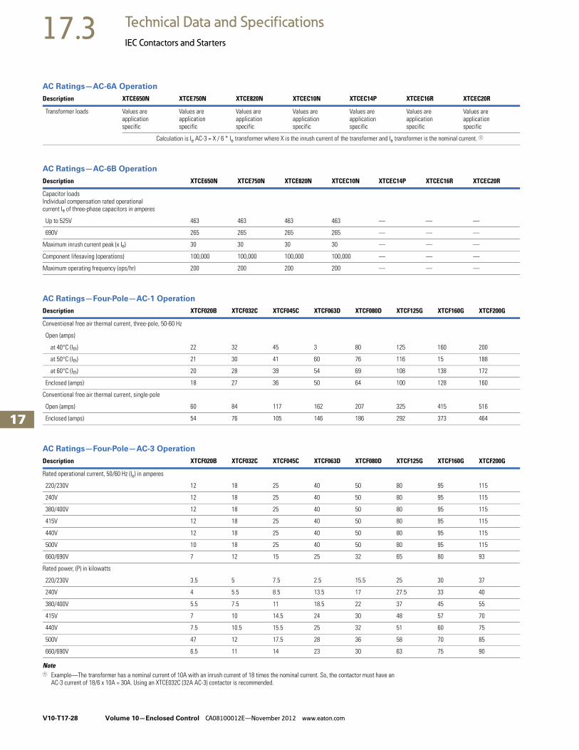
AC Ratings—AC-1 Operation
AC Ratings—AC-3 Operation
Note1 At maximum permissible ambient temperature.
Description XTCE007B XTCE009B XTCE012B XTCE015B XTCE018C XTCE025C XTCE032C
Conventional free air thermal current, three-pole, 50–60 Hz
Open
at 40°C (Ith) 22A 22A 22A 22A 40A 45A 45A
at 50°C (Ith) 21A 21A 21A 21A 38A 43A 43A
at 55°C (Ith) 21A 21A 21A 21A 37A 42A 42A
at 60°C (Ith) 20A 20A 20A 20A 35A 40A 40A
Enclosed 18A 18A 18A 18A 32A 36A 36A
Conventional free air thermal current, single-pole (Ith)
Open 50A 50A 50A 50A 88A 100A 100A
Enclosed 45A 45A 45A 45A 80A 90A 90A
Description XTCE007B XTCE009B XTCE012B XTCE015B XTCE018C XTCE025C XTCE032C
Rated operational current, 50/60 Hz 1 (Ie) in amperes
220/230V 7 9 12 15.5 18 25 32
240V 7 9 12 15.5 18 25 32
380/400V 7 9 12 15.5 18 25 32
415V 7 9 12 15.5 18 25 32
440V 7 9 12 15.5 18 25 32
500V 5 7 10 12.5 18 25 32
660/690V 4 5 7 9 12 15 18
1000V — — — — — — —
Rated power (P) in kilowatts
220/230V 2.2 2.5 3.5 4 5 7.5 10
240V 2.2 3 4 4.6 5.5 8.5 11
380/400V 3 4 5.5 7.5 7.5 11 15
415V 4 5.5 7 8 10 14.5 19
440V 4.5 5.5 7.5 8.4 10.5 15.5 20
500V 3.5 4.5 7 7.5 12 17.5 23
660/690V 3.5 4.5 6.5 7 11 14 17
1000V — — — — — — —
Volume 10—Enclosed Control CA08100012E—November 2012 www.eaton.com V10-T17-21
17
17
17
17
17
17
17
17
17
17
17
17
17
17
17
17
17
17
17
17
17
17
17
17
17
17
17
17
17
17
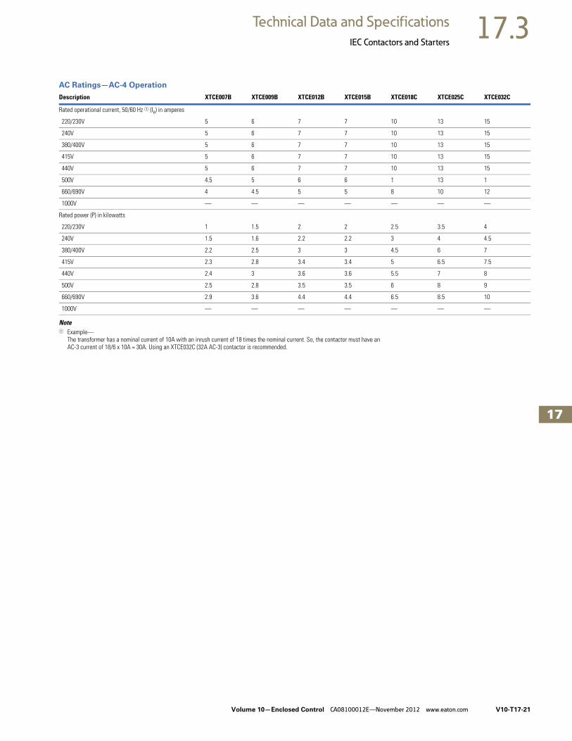
17.3Technical Data and Specifications
IEC Contactors and Starters
AC Ratings—AC-4 Operation
Note1 Example—
The transformer has a nominal current of 10A with an inrush current of 18 times the nominal current. So, the contactor must have an AC-3 current of 18/6 x 10A = 30A. Using an XTCE032C (32A AC-3) contactor is recommended.
Description XTCE007B XTCE009B XTCE012B XTCE015B XTCE018C XTCE025C XTCE032C
Rated operational current, 50/60 Hz 1 (Ie) in amperes
220/230V 5 6 7 7 10 13 15
240V 5 6 7 7 10 13 15
380/400V 5 6 7 7 10 13 15
415V 5 6 7 7 10 13 15
440V 5 6 7 7 10 13 15
500V 4.5 5 6 6 1 13 1
660/690V 4 4.5 5 5 8 10 12
1000V — — — — — — —
Rated power (P) in kilowatts
220/230V 1 1.5 2 2 2.5 3.5 4
240V 1.5 1.6 2.2 2.2 3 4 4.5
380/400V 2.2 2.5 3 3 4.5 6 7
415V 2.3 2.8 3.4 3.4 5 6.5 7.5
440V 2.4 3 3.6 3.6 5.5 7 8
500V 2.5 2.8 3.5 3.5 6 8 9
660/690V 2.9 3.6 4.4 4.4 6.5 8.5 10
1000V — — — — — — —

V10-T17-22 Volume 10—Enclosed Control CA08100012E—November 2012 www.eaton.com
17
17
17
17
17
17
17
17
17
17
17
17
17
17
17
17
17
17
17
17
17
17
17
17
17
17
17
17
17
17
17.3 Technical Data and Specifications
IEC Contactors and Starters
AC Ratings—AC-6A Operation
AC Ratings—AC-6B Operation
AC Ratings—AC-1 Operation
Notes1 Example—
The transformer has a nominal current of 10A with an inrush current of 18 times the nominal current. So, the contactor must have an AC-3 current of 18/6 x 10A = 30A. Using an XTCE032C (32A AC-3) contactor is recommended.
2 For 225–275A, use 2X 70 mm2 wire.3 At maximum permissible ambient temperature.
Description XTCE007B XTCE009B XTCE012B XTCE015B XTCE018C XTCE025C XTCE032C
Transformer loads Values are application specific
Values are application specific
Values are application specific
Values are application specific
Values are application specific
Values are application specific
Values are application specific
Calculation is Ie AC-3 = X / 6 * Ie transformer where X is the inrush current of the transformer and Ie transformer is the nominal current. 1
Description XTCE007B XTCE009B XTCE012B XTCE015B XTCE018C XTCE025C XTCE032C
Capacitor loadsIndividual compensation rated operational current Ie of three-phase capacitors in amperes
Up to 525V See Volume 5—Motor Control and Protection, CA08100006E, Tab 27 for capacitor ratings
690V See Volume 5—Motor Control and Protection, CA08100006E, Tab 27 for capacitor ratings
Maximum inrush current peak (x Ie) 30 30 30 30 30 30 30
Component lifesaving (operations) — — — — — — —
Maximum operating frequency (ops/hr) — — — — — — —
Description XTCE040D XTCE050D XTCE065D XTCE072D XTCE080F XTCE095F XTCE115G XTCE150G XTCE170G
Conventional free air thermal current, three-pole, 50–60 Hz
Open
at 40°C (Ith) 60A 80A 98A 98A 110A 130A 160A 190A 275A 2
at 50°C (Ith) 57A 71A 88A 88A 98A 125A 142A 180A 200A
at 55°C (Ith) 55A 68A 83A 83A 94A 115A 135A 170A 190A
at 60°C (Ith) 50A 65A 80A 80A 90A 110A 130A 160A 185A
Enclosed 45A 58A 72A 72A 80A 100A 115A 144A 166A
Conventional free air thermal current, single-pole (Ith)
Open 125A 162A 200A 200A 225A 275A 325A 400A 460A
Enclosed 112A 145A 180A 180A 200A 250A 285A 360A 415A

Volume 10—Enclosed Control CA08100012E—November 2012 www.eaton.com V10-T17-23
17
17
17
17
17
17
17
17
17
17
17
17
17
17
17
17
17
17
17
17
17
17
17
17
17
17
17
17
17
17
17.3Technical Data and Specifications
IEC Contactors and Starters
AC Ratings—AC-3 Operation
AC Ratings—AC-4 Operation
Note1 At maximum permissible ambient temperature.
Description XTCE040D XTCE050D XTCE065D XTCE072D XTCE080F XTCE095F XTCE115G XTCE150G XTCE170G
Rated operational current, 50/60 Hz 1 (Ie) in amperes
220/230V 40 50 65 72 80 95 115 150 170
240V 40 50 65 72 80 95 115 150 170
380/400V 40 50 65 7 80 95 115 150 170
415V 40 50 65 72 80 95 115 150 170
440V 40 50 65 72 80 95 115 15 170
500V 40 50 65 72 80 95 115 150 170
660/690 25 32 37 37 65 80 93 100 150
1000V — — — — — — — — —
Rated power (P) in kilowatts
220/230V 12.5 15.5 20 22 25 30 37 48 52
240V 13.5 17 22 35 27.5 34 40 52 57
380/400V 18.5 22 30 37 37 45 55 75 90
415V 24 30 39 41 43 57 70 91 100
440V 25 32 41 44 51 60 75 95 105
500V 28 36 47 45 58 70 85 110 120
660/690V 23 30 35 35 63 75 90 96 140
1000V — — — — — — — — —
Description XTCE040D XTCE050D XTCE065D XTCE072D XTCE080F XTCE095F XTCE115G XTCE150G XTCE170G
Rated operational current, 50/60 Hz 1 (Ie) in amperes
220/230V 18 21 25 25 40 50 55 65 65
240V 18 21 25 25 40 50 55 65 65
380/400V 18 21 25 25 40 50 55 65 65
415V 18 21 25 25 40 50 55 65 65
440V 18 21 25 25 40 50 55 65 65
500V 18 21 25 25 40 50 55 65 65
660/690V 14 17 20 20 40 50 45 50 50
1000V — — — — — — — — —
Rated power (P) in kilowatts
220/230V 5 6 7 7 12 16 17 20 20
240V 5.5 6.5 7.5 7.5 13 17 19 22 22
380/400V 9 10 12 12 20 26 28 33 33
415V 9.5 11 13 13 24 30 33 39 39
440V 10 12 14 14 25 32 35 41 41
500V 11 13 16 16 29 36 40 47 47
660/690V 12 14 17 17 26 35 43 48 48
1000V — — — — — — — — —

V10-T17-24 Volume 10—Enclosed Control CA08100012E—November 2012 www.eaton.com
17
17
17
17
17
17
17
17
17
17
17
17
17
17
17
17
17
17
17
17
17
17
17
17
17
17
17
17
17
17
17.3 Technical Data and Specifications
IEC Contactors and Starters
AC Ratings—AC6-A Operation
AC Ratings—AC6-B Operation
AC Ratings—AC-1 Operation
Note1 Example—The transformer has a nominal current of 10A with an inrush current of 18 times the nominal current. So, the contactor must have an
AC-3 current of 18/6 x 10A = 30A. Using an XTCE032C (32A AC-3) contactor is recommended.
Description XTCE040D XTCE050D XTCE065D XTCE072D XTCE080F XTCE095F XTCE115G XTCE150G XTCE170G
Transformer loads Values are application specific
Values are application specific
Values are application specific
Values are application specific
Values are application specific
Values are application specific
Values are application specific
Values are application specific
Values are application specific
Calculation is Ie AC-3 = X / 6 * Ie transformer where X is the inrush current of the transformer and Ie transformer is the nominal current. 1
Description XTCE040D XTCE050D XTCE065D XTCE072D XTCE080F XTCE095F XTCE115G XTCE150G XTCE170G
Capacitor loadsIndividual compensation rated operational current Ie of three-phase capacitors in amperes
Up to 525V See Volume 5—Motor Control and Protection, CA08100006E, Tab 27 for capacitor ratings
690V See Volume 5—Motor Control and Protection, CA08100006E, Tab 27 for capacitor ratings
Maximum inrush current peak (x Ie) 30 30 30 30 30 30 30 30 30
Component lifesaving (operations) — — — — — — — — —
Maximum operating frequency (ops/hr) — — — — — — — — —
Description XTCE185L XTCE225L XTCE250L XTCE300M XTCE400M XTCE500M XTCE570M XTCE580N
Conventional free air thermal current, three-pole, 50–60 Hz
at 40°C (Ith) 337 386 429 490 612 857 857 980
at 50°C (Ith) 301 345 383 438 548 767 767 876
at 55°C (Ith) 287 329 366 418 522 731 731 836
at 60°C (Ith) 275 315 350 400 500 700 700 800
Conventional free air thermal current, single-pole (Ith) 685 785 875 1000 1250 1750 1750 2000

Volume 10—Enclosed Control CA08100012E—November 2012 www.eaton.com V10-T17-25
17
17
17
17
17
17
17
17
17
17
17
17
17
17
17
17
17
17
17
17
17
17
17
17
17
17
17
17
17
17
17.3Technical Data and Specifications
IEC Contactors and Starters
AC Ratings—AC-3 Operation
AC Ratings—AC-4 Operation
Note1 At maximum permissible ambient temperature.
Description XTCE185L XTCE225L XTCE250L XTCE300M XTCE400M XTCE500M XTCE570M XTCE580N
Rated operational current, 50/60 Hz 1 (Ie) in amperes
220/230V 185 225 250 300 400 500 580 580
240V 185 225 250 300 400 500 580 580
380/400V 185 225 250 300 400 500 580 580
415V 185 225 250 300 400 500 580 580
440V 185 225 250 300 400 500 580 580
500V 185 225 250 300 400 500 580 580
660/690V 185 225 250 300 400 500 580 580
1000V 76 76 76 95 95 95 95 435
Rated power (P) in kilowatts
220/230V 55 70 75 90 125 155 185 185
240V 62 75 85 100 132 170 200 200
380/400V 90 110 132 160 200 250 315 315
415V 110 132 148 180 240 300 348 348
440V 115 142 157 190 255 345 370 370
500V 132 160 180 21 290 360 420 420
660/690V 175 215 240 286 344 344 344 560
1000V 108 108 108 132 132 132 132 600
Description XTCE185L XTCE225L XTCE250L XTCE300M XTCE400M XTCE500M XTCE570M XTCE580N
Rated operational current, 50/60 Hz 1 (Ie) in amperes
220/230V 136 164 200 240 296 360 360 456
240V 136 164 200 240 296 360 360 456
380/400V 136 164 200 240 296 360 360 456
415V 136 164 200 240 296 360 360 456
440V 136 164 200 240 296 360 360 456
500V 136 164 200 240 296 360 360 456
660/690V 136 164 200 240 296 360 360 456
1000V 76 76 76 95 95 95 95 348
Rated power (P) in kilowatts
220/230V 41 51 62 75 92 112 112 143
240V 45 54 68 82 101 122 122 156
380/400V 75 90 110 132 160 200 200 250
415V 80 96 117 142 176 216 216 274
440V 85 102 125 151 186 229 229 290
500V 96 116 143 172 214 260 260 330
660/690V 127 155 189 229 283 344 344 440
1000V 108 108 108 132 132 132 132 509

V10-T17-26 Volume 10—Enclosed Control CA08100012E—November 2012 www.eaton.com
17
17
17
17
17
17
17
17
17
17
17
17
17
17
17
17
17
17
17
17
17
17
17
17
17
17
17
17
17
17
17.3 Technical Data and Specifications
IEC Contactors and Starters
AC Ratings—AC-6A Operation
AC Ratings—AC-6B Operation
AC Ratings—AC-1 Operation
Notes1 Example—The transformer has a nominal current of 10A with an inrush current of 18 times the nominal current. So, the contactor must have an
AC-3 current of 18/6 x 10A = 30A. Using an XTCE032C (32A AC-3) contactor is recommended.2 Up to 690V.
Description XTCE185L XTCE225L XTCE250L XTCE300M XTCE400M XTCE500M XTCE570M XTCE580N
Transformer loads Values are application specific
Values are application specific
Values are application specific
Values are application specific
Values are application specific
Values are application specific
Values are application specific
Values are application specific
Calculation is Ie AC-3 = X / 6 * Ie transformer where X is the inrush current of the transformer and Ie transformer is the nominal current. 1
Description XTCE185L XTCE225L XTCE250L XTCE300M XTCE400M XTCE500M XTCE570M XTCE580N
Capacitor loadsIndividual compensation rated operational current Ie of three-phase capacitors in amperes
Up to 525V 220 220 220 307 307 307 307 463
690V 133 133 133 177 177 177 177 265
Maximum inrush current peak (x Ie) 30 30 30 30 30 30 30 30
Component lifesaving (operations) 100,000 100,000 100,000 100,000 100,000 100,000 100,000 100,000
Maximum operating frequency (ops/hr) 200 200 200 200 200 200 200 200
Description XTCE650N XTCE750N XTCE820N XTCEC10N XTCEC14P XTCEC16R XTCEC20R
Conventional free air thermal current, three-pole, 50–60 Hz
at 40°C (Ith) 1041 1102 1225 1225 1714 2 2200 2450 2
at 50°C (Ith) 931 986 1095 1095 1533 2 1970 2190 2
at 55°C (Ith) 888 940 1044 1044 1462 2 1800 2089 2
at 60°C (Ith) 850 900 1000 1000 1400 2 1800 2000 2
Conventional free air thermal current, single-pole (Ith)
2125 2250 2500 2500 3500 4500 5000

Volume 10—Enclosed Control CA08100012E—November 2012 www.eaton.com V10-T17-27
17
17
17
17
17
17
17
17
17
17
17
17
17
17
17
17
17
17
17
17
17
17
17
17
17
17
17
17
17
17
17.3Technical Data and Specifications
IEC Contactors and Starters
AC Ratings—AC-3 Operation
AC Ratings—AC-4 Operation
Note1 At maximum permissible ambient temperature.
Description XTCE650N XTCE750N XTCE820N XTCEC10N XTCEC14P XTCEC16R XTCEC20R
Rated operational current, 50/60 Hz 1 (Ie) in amperes
220/230V 650 750 820 1000 — 1600 —
240V 650 750 820 1000 — 1600 —
380/400V 650 750 820 1000 — 1600 —
415V 650 750 820 1000 — 1600 —
440V 650 750 820 1000 — 1600 —
500V 650 750 820 1000 — 1600 —
660/690V 650 750 820 1000 — 1600 —
1000V 435 580 580 700 — — —
Rated power (P) in kilowatts
220/230V 205 240 260 315 — 500 —
240V 225 260 285 340 — 550 —
380/400V 355 400 450 560 — 900 —
415V 390 455 500 610 — 930 —
440V 420 480 525 650 — 1000 —
500V 470 550 600 730 — 1180 —
660/690V 630 720 750 1000 — 1600 —
1000V 600 800 800 1000 — — —
Description XTCE650N XTCE750N XTCE820N XTCEC10N XTCEC14P XTCEC16R XTCEC20R
Rated operational current, 50/60 Hz 1 (Ie) in amperes
220/230V 512 576 656 800 — 1280 —
240V 512 576 656 800 — 1280 —
380/400V 512 576 656 800 — 1280 —
415V 512 576 656 800 — 1280 —
440V 512 576 656 800 — 1280 —
500V 512 576 656 800 — 1280 —
660/690V 512 576 656 800 — 1280 —
1000V 348 464 464 700 — — —
Rated power (P) in kilowatts
220/230V 161 181 209 260 — 30 —
240V 176 200 228 280 — 450 —
380/400V 280 315 355 450 — 750 —
415V 307 346 394 490 — 770 —
440V 32 367 41 520 — 830 —
500V 370 417 474 590 — 940 —
660/690V 494 556 633 780 — 1300 —
1000V 509 678 678 1000 — — —
V10-T17-28 Volume 10—Enclosed Control CA08100012E—November 2012 www.eaton.com
17
17
17
17
17
17
17
17
17
17
17
17
17
17
17
17
17
17
17
17
17
17
17
17
17
17
17
17
17
17
17.3 Technical Data and Specifications
IEC Contactors and Starters
AC Ratings—AC-6A Operation
AC Ratings—AC-6B Operation
AC Ratings—Four-Pole—AC-1 Operation
AC Ratings—Four-Pole—AC-3 Operation
Note1 Example—The transformer has a nominal current of 10A with an inrush current of 18 times the nominal current. So, the contactor must have an
AC-3 current of 18/6 x 10A = 30A. Using an XTCE032C (32A AC-3) contactor is recommended.
Description XTCE650N XTCE750N XTCE820N XTCEC10N XTCEC14P XTCEC16R XTCEC20R
Transformer loads Values are application specific
Values are application specific
Values are application specific
Values are application specific
Values are application specific
Values are application specific
Values are application specific
Calculation is Ie AC-3 = X / 6 * Ie transformer where X is the inrush current of the transformer and Ie transformer is the nominal current. 1
Description XTCE650N XTCE750N XTCE820N XTCEC10N XTCEC14P XTCEC16R XTCEC20R
Capacitor loadsIndividual compensation rated operational current Ie of three-phase capacitors in amperes
Up to 525V 463 463 463 463 — — —
690V 265 265 265 265 — — —
Maximum inrush current peak (x Ie) 30 30 30 30 — — —
Component lifesaving (operations) 100,000 100,000 100,000 100,000 — — —
Maximum operating frequency (ops/hr) 200 200 200 200 — — —
Description XTCF020B XTCF032C XTCF045C XTCF063D XTCF080D XTCF125G XTCF160G XTCF200G
Conventional free air thermal current, three-pole, 50-60 Hz
Open (amps)
at 40°C (Ith) 22 32 45 3 80 125 160 200
at 50°C (Ith) 21 30 41 60 76 116 15 188
at 60°C (Ith) 20 28 39 54 69 108 138 172
Enclosed (amps) 18 27 36 50 64 100 128 160
Conventional free air thermal current, single-pole
Open (amps) 60 84 117 162 207 325 415 516
Enclosed (amps) 54 76 105 146 186 292 373 464
Description XTCF020B XTCF032C XTCF045C XTCF063D XTCF080D XTCF125G XTCF160G XTCF200G
Rated operational current, 50/60 Hz (Ie) in amperes
220/230V 12 18 25 40 50 80 95 115
240V 12 18 25 40 50 80 95 115
380/400V 12 18 25 40 50 80 95 115
415V 12 18 25 40 50 80 95 115
440V 12 18 25 40 50 80 95 115
500V 10 18 25 40 50 80 95 115
660/690V 7 12 15 25 32 65 80 93
Rated power, (P) in kilowatts
220/230V 3.5 5 7.5 2.5 15.5 25 30 37
240V 4 5.5 8.5 13.5 17 27.5 33 40
380/400V 5.5 7.5 11 18.5 22 37 45 55
415V 7 10 14.5 24 30 48 57 70
440V 7.5 10.5 15.5 25 32 51 60 75
500V 47 12 17.5 28 36 58 70 85
660/690V 6.5 11 14 23 30 63 75 90
Volume 10—Enclosed Control CA08100012E—November 2012 www.eaton.com V10-T17-29
17
17
17
17
17
17
17
17
17
17
17
17
17
17
17
17
17
17
17
17
17
17
17
17
17
17
17
17
17
17
17.3Technical Data and Specifications
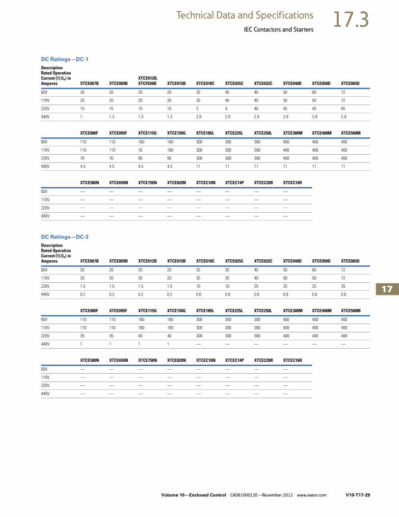
IEC Contactors and Starters
DC Ratings—DC-1
DC Ratings—DC-3
DescriptionRated Operation Current {1} (Ie) in Amperes XTCE007B XTCE009B
XTCE012B,XTCF020B XTCE015B XTCE018C XTCE025C XTCE032C XTCE040D XTCE050D XTCE065D
60V 20 20 20 20 35 40 40 50 60 72
110V 20 20 20 20 35 40 40 50 50 72
220V 15 15 15 15 3 4 40 45 45 65
440V 1 1.3 1.3 1.3 2.9 2.9 2.9 2.9 2.9 2.9
XTCE080F XTCE095F XTCE115G XTCE150G XTCE185L XTCE225L XTCE250L XTCE300M XTCE400M XTCE500M
60V 110 110 160 160 300 300 300 400 400 400
110V 110 110 16 160 300 300 300 400 400 400
220V 70 70 90 90 300 300 300 400 400 400
440V 4.5 4.5 4.5 4.5 11 11 11 11 11 11
XTCE580N XTCE650N XTCE750N XTCE820N XTCEC10N XTCEC14P XTCEC20R XTCEC16R
60V — — — — — — — —
110V — — — — — — — —
220V — — — — — — — —
440V — — — — — — — —
DescriptionRated Operation Current {1} (Ie) in Amperes XTCE007B XTCE009B XTCE012B XTCE015B XTCE018C XTCE025C XTCE032C XTCE040D XTCE050D XTCE065D
60V 20 20 20 20 35 35 40 50 60 72
110V 20 20 20 20 35 35 40 50 50 72
220V 1.5 1.5 1.5 1.5 10 10 25 25 25 35
440V 0.2 0.2 0.2 0.2 0.6 0.6 0.6 0.6 0.6 0.6
XTCE080F XTCE095F XTCE115G XTCE150G XTCE185L XTCE225L XTCE250L XTCE300M XTCE400M XTCE500M
60V 110 110 160 160 300 300 300 400 400 400
110V 110 110 160 160 300 300 300 400 400 400
220V 35 35 40 40 300 300 300 400 400 400
440V 1 1 1 1 — — — — — —
XTCE580N XTCE650N XTCE750N XTCE820N XTCEC10N XTCEC14P XTCEC20R XTCEC16R
60V — — — — — — — —
110V — — — — — — — —
220V — — — — — — — —
440V — — — — — — — —

V10-T17-30 Volume 10—Enclosed Control CA08100012E—November 2012 www.eaton.com
17
17
17
17
17
17
17
17
17
17
17
17
17
17
17
17
17
17
17
17
17
17
17
17
17
17
17
17
17
17
17.3 Technical Data and Specifications
IEC Contactors and Starters
DC Ratings—DC-5
DC Ratings—Four-Pole—DC-1 Operation
DC Ratings—Four-Pole—DC-3 Operation
DC Ratings—Four-Pole—DC-5 Operation
DescriptionRated Operation Current {1} (Ie) in Amperes XTCE007B XTCE009B XTCE012B XTCE015B XTCE018C XTCE025C XTCE032C XTCE040D XTCE050D XTCE065D
60V 20 20 20 20 35 35 40 50 60 72
110V 20 20 20 20 35 35 40 50 50 72
220V 1.5 1.5 1.5 1.5 10 10 25 25 25 35
440V 0.2 0.2 0.2 0.2 0.6 0.6 0.6 0.6 0.6 0.6
XTCE080F XTCE095F XTCE115G XTCE150G XTCE185L XTCE225L XTCE250L XTCE300M XTCE400M XTCE500M
60V 110 110 160 160 300 300 300 400 400 400
110V 110 110 160 160 300 300 300 400 400 400
220V 35 35 40 40 300 300 300 400 400 400
440V 1 1 1 1 — — — — — —
XTCE580N XTCE650N XTCE750N XTCE820N XTCEC10N XTCEC14P XTCEC20R
60V — — — — — — —
110V — — — — — — —
220V — — — — — — —
440V — — — — — — —
DescriptionRated Operation Current {1} (Ie) in Amperes XTCF020B XTCF032C XTCF045C XTCF063D XTCF080D XTCF125G XTCF160G XTCF200G
60V 22 32 45 63 80 125 160 200
110V 22 32 45 6 80 125 160 200
220V 6 32 45 63 80 125 160 200
440V 1.3 3 3 5 5 100 125 150
DescriptionRated Operation Current {1} (Ie) in Amperes XTCF020B XTCF032C XTCF045C XTCF063D XTCF080D XTCF125G XTCF160G XTCF200G
60V 20 32 45 63 80 125 160 200
110V 20 32 45 63 80 125 160 200
220V 1.5 32 45 63 80 125 160 200
440V 0.2 6 6 8 8 75 95 115
DescriptionRated Operation Current {1} (Ie) in Amperes XTCF020B XTCF032C XTCF045C XTCF063D XTCF080D XTCF125G XTCF160G XTCF200G
60V 20 32 45 63 80 125 160 200
110V 20 25 32 508 80 125 160 200
220V 1.5 15 22 38 70 100 125 150
440V 0.2 4 4 8 8 60 75 90

Volume 10—Enclosed Control CA08100012E—November 2012 www.eaton.com V10-T17-31
17
17
17
17
17
17
17
17
17
17
17
17
17
17
17
17
17
17
17
17
17
17
17
17
17
17
17
17
17
17
17.3Technical Data and Specifications
IEC Contactors and Starters
Life Curves
Normal Switching Duty
Extreme Switching Duty
AkW
150
115
9580
65
50
40
32
25
18
12
9
7
5
4
3
2
AC-3/400V
75
55
45
37
30
22
18.5
15
11
7.5
5.5
4
3
0.01 0.02 0.04 0.06 0.1 0.2 0.4 0.6 1 2 4 6 10
XTCE032C
XTCE050D
XTCE025C
XTCE015B
XTCE040D
XTCE065D
XTCE080F
XTCE115G
XTCE095F
XTCE150G
XTCE018C
XTCE012B
XTCE009B
XTCE007B
Ra
ted
Ou
tpu
t o
f T
hre
e-P
ha
se
Mo
tors
50
–6
0 H
z
Ra
ted
Op
era
tio
na
l C
urr
en
t I e
50
–6
0 H
z
Component Lifespan (Millions of operations)
kW
AC-3/400V
A
Ra
ted
Ou
tpu
t o
f T
hre
e-P
ha
se
Mo
tors
50
–6
0 H
z
Ra
ted
Op
era
tio
na
l C
urr
en
t I e
50
–6
0 H
z
Component Lifespan (Millions of operations)
XTCE185L
XTCE225L
XTCE250M
XTCE300M
XTCE400M
XTCE500M
XTCE580N
XTCE650N
XTCE750N
XTCE820N
XTCEC10N
0.02 0.04 0.06 0.1 0.2 0.4 0.6 1 2 4 6 100.01
820
750
650
580
500
400
300
250
225
185
145
104
85
72
58
43
36
30
23
16
1000
132
110
90
75
55
45
37
30
22
18.5
15
11
7.5
450
560
400
355315
250
200
160
XTCE007B–XTCE150G XTCE185L–XTCEC10N
AkW
100908066
403532
20
17
13
98.3
6.5
52474133
191715
9
7.5
5.5
43.5
2.5
5
4
3
2
AC-4/400V
XTCE150G
XTCE095F
XTCE065D
XTCE040D
XTCE032C
XTCE012 (and 015)B
XTCE007B
XTCE115G
XTCE080F
XTCE050D
XTCE025C
XTCE009B
0.01 0.02 0.04 0.06 0.1 0.2 0.4 0.6 1 2 4 6 10
Ra
ted
Ou
tpu
t o
f T
hre
e-P
ha
se
Mo
tors
50
–6
0 H
z
Ra
ted
Op
era
tio
na
l C
urr
en
t I e
50
–6
0 H
z
Component Lifespan (Millions of operations)
kW AC-4/400VA
Ra
ted
Ou
tpu
t o
f T
hre
e-P
ha
se
Mo
tors
50
–6
0 H
z
Ra
ted
Op
era
tio
na
l C
urr
en
t I e
50
–6
0 H
z
Component Lifespan (Millions of operations)
0.02 0.04 0.06 0.1 0.2 0.4 0.6 1 2 4 6 100.01
315280
200
160
110
90
75
55
45
37
30
22
18.5
15
11
7.5
5.5
4
3
2.2
1.5
576
355 656
512
360
250 456
296
200
132 240
164
140
85
104
72
58
43
36
30
23
16
12
8.8
6.5
3.5
XTCE185L
XTCE225L
XTCE250M
XTCE300M
XTCE750N
XTCE820N
XTCE650NXTCE580NXTCE500M
XTCE400M
5
XTCE007B–XTCE150G XTCE185L–XTCE820N

V10-T17-32 Volume 10—Enclosed Control CA08100012E—November 2012 www.eaton.com
17
17
17
17
17
17
17
17
17
17
17
17
17
17
17
17
17
17
17
17
17
17
17
17
17
17
17
17
17
17
17.3 Technical Data and Specifications
IEC Contactors and Starters
Switching Duty for Non-Motor Loads, Three-Pole, Four-Pole—XTCE185L–XTCEC14P Short-Time Loading, Three-Pole—XTCE185L–XTCEC20R
Maximum Operating Frequency—Related to Rating and Utilization Category (400V)
Note1 PN = maximum motor rating (kW/hp) of the relevant contactor.
ops/hr = maximum number of operations per hour.
AC-1/400V
Bre
akin
g C
urr
en
t A
Component Lifespan (Millions of operations)
0.1 0.2 0.5 70.7 1 3 5 10
2
1
3
4
0.3 2
5
900850
1400
1000
700800
500
400
275300
350
160
100
55
35
20
10
7
XTCE185LXTCE225L
XTCE400M
XTCE300MXTCE250M
XTCE750NXTCE650N
XTCE500MXTCE580N
XTCEC14P
XTCE820N/XTCEC10N
10Min
15Min
1Min
3Min
5Min
Seconds
AC-1/400VA
Sh
ort
-Tim
e C
urr
en
t
Duration of Load
XTCEC10N, XTCEC14P, XTCEC20R
900
30070 1005020 303 5 7 102
8000
10000
6000
5000
4000
3000
2500
2000
1000
700
500
400
300
1500
XTCE185L/XTCE225L
XTCE250M
XTCE300M
XTCE400M
XTCE500M
700200 500
200
XTCE580NXTCE650NXTCE750N
XTCE820N
6000
4000
2000
1000
800
600
400
200
100
0 10 20 30 40 50 60 70 80 90 100 %
PN (kW/hp)
1
2
5
3
4
Ops/hr
Utilization Category 1
Characteristic Curve Above
Type AC-1 AC-3AC-2AC-4
XTCE007B–XTCE015B 3 1 5
XTCE018C–XTCE032C 3 2 5
XTCE040D–XTCE065D 3 2 5
XTCE080F–XTCE150G 3 4 5
PN (kW/hp)
Ops/hr
4000
3000
2000
600
500
400
300
200
150
100
500 10 20 30 40 50 60 70 80 90 100 %
1500
1000
800
ab
d
c
e
f
g
Utilization Category 1
Type
Characteristic Curve Above
Type
Characteristic Curve Above
AC-1 AC-3 AC-4 AC-1 AC-3 AC-4
XTCE185L 2 1 6 XTCE500M 3 2 7
XTCE225L 2 1 6 XTCE580N 3 4 5
XTCE250L 2 1 6 XTCE650N 3 4 5
XTCE300M 3 2 7 XTCE750N 3 4 5
XTCE400M 3 2 7 XTCE820N 3 4 5
7–150 hp 185–820 hp

Volume 10—Enclosed Control CA08100012E—November 2012 www.eaton.com V10-T17-33
17
17
17
17
17
17
17
17
17
17
17
17
17
17
17
17
17
17
17
17
17
17
17
17
17
17
17
17
17
17
17.3Technical Data and Specifications
IEC Contactors and Starters
Overload Relays
XTOB Overload Relay—Technical Data and Specifications
Notes1 Ambient temperature operating range to IEC/EN 60947, PTB: –5° to 50°C.2 Consult factory.3 6 mm2 flexible with ferrules to DIN 46228.4 Main contact terminal capacity, solid and stranded conductors with ferrules: When using 2 conductors use identical cross-section.
DescriptionXTOB…BC1, XTOB…CC1 XTOB…DC1
XTOB…GC1, XTOB…GC1S XTOB...LC1
General
Standards IEC/EN 60947, VDE 0660, UL, CSA
Climate proofing Damp heat, constant, to IEC 60068-2-78; damp heat, cyclic, to IEC 60068-2-30
Ambient temperature 1 –25° to 55°C (–13° to 131°F)
–25° to 55°C (–13° to 131°F)
–25° to 55°C (–13° to 131°F)
–25° to 50°C(–13° to 122°F)
Temperature compensation Continuous Continuous Continuous Continuous
Mechanical shock resistance (IEC/EN 60068-2-27)half-sinusoidal shock 10 ms 10g 10g 10g 10g
Degree of protection IP20 IP20 IP20 P00
Protection against direct contact when actuated from front (IEC 536)
Finger- and back ofhand-proof
Finger- and back of hand-proof
Finger- and back of hand-proof
With terminal cover XTOBXTS...L
Insulation voltage (Ui) Vac 690 690 690 1000
Overvoltage category/pollution degree III/3 III/3 III/3 III/3
Impulse withstand voltage (Uimp) Vac 6000 6000 6000 8000
Operational voltage (Ue) Vac 690 690 690 1000
Safe isolation to VDE 0106 Part 101 and Part 101/A1
Between auxiliary contacts and main contacts (Vac) 440 440 440 440
Between main contacts (Vac) 440 440 440 440
Overload release setting range 0.1–32A 6–75A 25–150A 50–250A
Short-circuit protection maximum fuse 2 2 2 2
Temperature compensation residual error >40°C <0.25 <0.25 <0.25 <0.25
Current heat loss (three conductors)
Lower value of setting range, W 2.5 3 16 16
Upper value of setting range 6 7.5 28 28
Terminal capacity
Solid, mm2 2 x (1–6) 2 x (1–16) 2 x (4–16) —
Flexible with ferrule, mm2 2 x (1–4)2 x (1–6) 3
1 x 252 x (1–10) 4
1 x (4–70)2 x (4–50)
—
Flexible with cable lug, mm2 — — — 95
Stranded with cable lug, mm2 — — — 120
Solid or stranded, AWG 14–8 14–2 2/0 250 kcmil
Flat conductor—number of segments x width x thickness (mm2)
— — — 6 x 16 x 18
Bus bar—width (mm) — — — 20 x 3
Terminal screw M4 M6 M10 M8 x 25
Tightening torque
Nm 1.8 3.5 10 24
Lb-in 16 31 88.5 221.3
Tools
Pozidriv screwdriver Size 2 Size 2 — —
Standard screwdriver 1 x 6 1 x 6 — —
Hexagon socket head spanner (SW) — — 5 mm 13 mm

V10-T17-34 Volume 10—Enclosed Control CA08100012E—November 2012 www.eaton.com
17
17
17
17
17
17
17
17
17
17
17
17
17
17
17
17
17
17
17
17
17
17
17
17
17
17
17
17
17
17
17.3 Technical Data and Specifications
IEC Contactors and Starters
XTOB Overload Relay—Technical Data and Specifications, continued
Note1 Rated operational current: Making and breaking conditions to DC-13, L/R constant as stated.
DescriptionXTOB…BC1, XTOB…CC1 XTOB…DC1
XTOB…GC1, XTOB…GC1S XTOB...LC1
Auxiliary and Control Circuit Connections
Impulse withstand voltage (Uimp) Vac 6000 6000 6000 6000
Overvoltage category/pollution degree III/3 III/3 III/3 III/3
Terminal capacity
Solid, mm2 2 x (0.75–4) 2 x (0.75–4) 2 x (0.75–4) 2 x (0.75–4)
Flexible with ferrule, mm2 2 x (0.75–2.5) 2 x (0.75–2.5) 2 x (0.75–2.5) 2 x (0.75–2.5)
Solid or stranded (AWG) 2 x (18–12) 2 x (18–12) 2 x (18–12) 2 x (18–12)
Terminal screw M3.5 M3.5 M3.5 M3.5
Tightening torque
Nm 0.8–1.2 0.8–1.2 0.8–1.2 0.8–1.2
Lb-in 7–10.6 7–10.6 7–10.6 7–10.6
Tools
Pozidriv screwdriver Size 2 Size 2 Size 2 Size 2
Standard screwdriver 1 x 6 1 x 6 1 x 6 1 x 6
Rated insulated voltage (Ui) Vac 500 500 500 500
Rated operational voltage 500 500 500 500
Safe Isolation to VDE 0106 Part 101 and Part 101/A1between auxiliary contacts 240 240 240 240
Conventional thermal current, Ith 6 6 6 —
Rated operational current—AC-15
Make contact
120V 1.5 1.5 1.5 1.5
240V 1.5 1.5 1.5 1.5
415V 0.5 0.5 0.5 0.5
500V 0.5 0.5 0.5 0.5
Break contact
120V 1.5 1.5 1.5 1.5
240V 1.5 1.5 1.5 1.5
415V 0.9 0.9 0.9 0.9
500V 0.8 0.8 0.8 0.8
Rated operational current—DC-13 L/R <15 ms 1
24V 0.9 0.9 0.9 0.9
60V 0.75 0.75 0.75 0.75
110V 0.4 0.4 0.4 0.4
220V 0.2 0.2 0.2 0.2
Short-circuit rating without welding
Maximum fuse, A gG/gL 6 6 6 6

Volume 10—Enclosed Control CA08100012E—November 2012 www.eaton.com V10-T17-35
17
17
17
17
17
17
17
17
17
17
17
17
17
17
17
17
17
17
17
17
17
17
17
17
17
17
17
17
17
17
17.3Technical Data and Specifications
IEC Contactors and Starters
Tripping CharacteristicsThese tripping characteristics are the mean values of the spread at 20°C ambient temperature in a cold state.
Tripping time depends on response current. With devices at operating temperature, the tripping time of the overload relay reduces to approximately 25% of the read off value. Specific characteristics for each individual setting range can be found in MN03402001E.
Tripping Characteristics
Instructional Leaflets
Instructional Leaflets
Publication Number Description
Pub51221 XTOB, D Frame Overload Relays (inside of packaging)
Pub51222 XTOB, B–C Frame Overload Relays (inside of packaging)
2h100
6040
20
10
64
2
1
40
20
10
64
2
1
0.6
XTOB...BC1,XTOB...CC1,XTOB...DC1
1 1.5 2 3 4 6 8 10 15 20
x Setting Current
Two-PhaseSe
co
nd
sM
inu
tes
Three-Phase
2h100
6040
20
10
64
2
1
40
20
10
64
2
1
0.6
XTOB...GC1
1 1.5 2 3 4 6 8 10 15 20
x Setting Current
Two-PhaseSe
co
nd
sM
inu
tes
Three-Phase
2h100
6040
20
10
64
2
1
40
20
10
64
2
1
0.6
XTOB...LC1
1 1.5 2 3 4 6 8 10 15 20
x Setting Current
Two-PhaseSe
co
nd
sM
inu
tes
Three-Phase

V10-T17-36 Volume 10—Enclosed Control CA08100012E—November 2012 www.eaton.com
17
17
17
17
17
17
17
17
17
17
17
17
17
17
17
17
17
17
17
17
17
17
17
17
17
17
17
17
17
17
17.4 Technical Data and Specifications
Solid State Overload Relay
C440/XTOEElectronic Overload Relays up to 1500A
SpecificationDescription 45 mm 55 mm 110 mm
Electrical Ratings Range Range Range
Operating voltage (three-phase) and frequency 690 Vac (60/50 Hz) 690 Vac (60/50 Hz) 690 Vac (60/50 Hz)
FLA Range
0.33–1.65A1–5A4–20A9–45A
20–100A 28–140A (NEMA)35–175A (IEC)
Use with Contactors
XT IEC frames B, C, D F, G G, H
Freedom NEMA sizes 00, 0, 1, 2 3 4
Trip Class
10A, 10, 20, 30Selectable
10A, 10, 20, 30Selectable
10A, 10, 20, 30Selectable
Motor Protection
Thermal overload setting 1.05 x FLA: does not trip1.15 x FLA: overload trip
1.05 x FLA: does not trip1.15 x FLA: overload trip
1.05 x FLA: does not trip1.15 x FLA: overload trip
Feature Range Range Range
Phase loss Fixed threshold 50% Fixed threshold 50% Fixed threshold 50%
Phase unbalance (selectable: enable/disable) Fixed threshold 50% Fixed threshold 50% Fixed threshold 50%
Ground fault (selectable: enable/disable) 50% of FLA dial setting>150% = 2 sec>250% = 1 sec
50% of FLA dial setting>150% = 2 sec>250% = 1 sec
50% of FLA dial setting>150% = 2 sec>250% = 1 sec
Reset Manual/automatic Manual/automatic Manual/automatic
Indicators
Trip status Orange flag Orange flag Orange flag
Mode LED One flash: Overload operating properlyTwo flashes: Current is above FLA dial setting—pending trip
One flash: Overload operating properlyTwo flashes: Current is above FLA dial setting—pending trip
One flash: Overload operating properlyTwo flashes: Current is above FLA dial setting—pending trip
Options
Remote reset Yes Yes Yes
Reset bar Yes Yes Yes
Communication expansion module Yes Yes Yes
Communication adapter Yes Yes Yes
Capacity
Load terminals
Terminal capacity 12–10 AWG (4–6 mm2) 8–6 AWG (6–16 mm2)
6–1 AWG (16–50 mm2) 8–4/0 AWG (10–95 mm2)
Tightening torque 20–25 lb-in (2.3–2.8 Nm)25–30 lb-in (2.8–3.4 Nm)
25–30 lb-in (2.8–3.4 Nm) 124 lb-in (14 Nm)
Input, auxiliary contact and remote reset terminals
Terminal capacity 2 x (18–12) AWG 2 x (18–12) AWG 2 x (18–12) AWG
Tightening torque 7–11 lb-in (0.8–1.2 Nm) 7–11 lb-in (0.8–1.2 Nm) 7–11 lb-in (0.8–1.2 Nm)
Voltages
Insulation voltage Ui (three-phase) 690 Vac 690 Vac 690 Vac
Insulation voltage Ui (control) 500 Vac 500 Vac 500 Vac
Rated impulse withstand voltage 6000 Vac 6000 Vac 6000 Vac
Overvoltage category/pollution degree III/3 III/3 III/3

Volume 10—Enclosed Control CA08100012E—November 2012 www.eaton.com V10-T17-37
17
17
17
17
17
17
17
17
17
17
17
17
17
17
17
17
17
17
17
17
17
17
17
17
17
17
17
17
17
17
17.4Technical Data and Specifications
Solid State Overload Relay
Electronic Overload Relays up to 1500A, continued
SpecificationDescription 45 mm 55 mm 110 mm
Auxiliary and Control Circuit Ratings
Conventional thermal continuous current 5A 5A 5A
Rated operational current—IEC AC-15
Make contact (1800 VA)
120V 15A 15A 15A
240V 15A 15A 15A
415V 0.5A 0.5A 0.5A
500V 0.5A 0.5A 0.5A
Break contact (180 VA)
120V 1.5A 1.5A 1.5A
240V 1.5A 1.5A 1.5A
415V 0.9A 0.9A 0.9A
500V 0.8A 0.8A 0.8A
IEC DC-13 (L/R F 15 ms1)
0–250V 1.0A 1.0A 1.0A
Rated operational current—UL B600
Make contact (3600 VA)
120V 30A 30A 30A
240V 15A 15A 15A
480V 7.5A 7.5A 7.5A
600V 6A 6A 6A
Break contact (360 VA)
120V 3A 3A 3A
240V 1.5A 1.5A 1.5A
480V 0.75A 0.75A 0.75A
600V 0.6A 0.6A 0.6A
R300—Vdc ratings (28 VA)
0–120V 0.22A 0.22A 0.22A
250V 0.11A 0.11A 0.11A
Short-Circuit Rating without Welding
Maximum fuse 6A gG/gL 6A gG/gL 6A gG/gL
Environmental Ratings
Ambient temperature (operating) –13° to 149°F (–25° to 65°C) –13° to 149°F (–25° to 65°C) –13° to 149°F (–25° to 65°C)
Ambient temperature (storage) –40° to 185°F (–40° to 85°C) –40° to 185°F (–40° to 85°C) –40° to 185°F (–40° to 85°C)
Operating humidity UL 991 (H3) 5% to 95% non-condensing 5% to 95% non-condensing 5% to 95% non-condensing
Altitude (no derating) NEMA ICS1 2000m 2000m 2000m
Shock (IEC 600068-2-27) 15g any direction 15g any direction 15g any direction
Vibration (IEC 60068-2-6) 3g any direction 3g any direction 3g any direction
Pollution degree per IEC 60947-4-1 3 for product (2 for pcb) 3 for product (2 for pcb) 3 for product (2 for pcb)
Ingress protection IP20 IP20 IP20
Protection against direct contact when actuated from front (IEC 536)
Finger- and back-of-hand proof Finger- and back-of-hand proof Finger- and back-of-hand proof
Mounting position Any Any Any
Climatic proofing Damp heat, constant to IEC 60068-2-30 Damp heat, constant to IEC 60068-2-30 Damp heat, constant to IEC 60068-2-30

V10-T17-38 Volume 10—Enclosed Control CA08100012E—November 2012 www.eaton.com
17
17
17
17
17
17
17
17
17
17
17
17
17
17
17
17
17
17
17
17
17
17
17
17
17
17
17
17
17
17
17.4 Technical Data and Specifications
Solid State Overload Relay
Electronic Overload Relays up to 1500A, continued
SpecificationDescription 45 mm 55 mm 110 mm
Electrical/EMC
Radiated emissions IEC 60947-4-1-Table 15 EN 55011 (CISPIR 11) Group 1, Class A, ISM
30 mHz to 1000 mHz 30 mHz to 1000 mHz 30 mHz to 1000 mHz
Conducted emissions IEC 60947-4-1-Table 14 EN 55011 (CISPIR 11) Group 1; Class ISM
0.15 mHz to 30 mHz 0.15 mHz to 30 mHz 0.15 mHz to 30 mHz
ESD immunity IEC 60947-4-1 (Table 13)
±8 kV air, ±6 kV contact ±8 kV air, ±6 kV contact ±8 kV air, ±6 kV contact
Radiated immunity IEC 60947-4-1 IEC 61000-4-3
10 V/m 80 mHz–1000 mHz 3 V/m from 1.4 to 2.7 gHz80% amplitude modulated1 kHz sine wave
10 V/m 80 mHz–1000 mHz 3 V/m from 1.4 to 2.7 gHz80% amplitude modulated1 kHz sine wave
10 V/m 80 mHz–1000 mHz 3 V/m from 1.4 to 2.7 gHz80% amplitude modulated1 kHz sine wave
Conducted immunity IEC 60947-4-1, IEC 61000-4-6
140 dub (10V rms) 150 kHz–100 mHz
140 dub (10V rms) 150 kHz–100 mHz
140 dub (10V rms) 150 kHz–100 mHz
Fast transient immunity IEC 60947-4-1 (Table 13) IEC 61000-4-4
±4 kV using direct method with accessory installed in expansion bay
±2 kV using direct method
±4 kV using direct method with accessory installed in expansion bay
±2 kV using direct method
±4 kV using direct method with accessory installed in expansion bay
±2 kV using direct method
Surge immunity IEC 60947-4-1 (Table 13) IEC 61000-4-5 a Class 4
Three-phase power inputs:±4 kV line-to-line (DM)±4 kV line-to-ground (CM)
Three-phase power inputs:±4 kV line-to-line (DM)±4 kV line-to-ground (CM)
Three-phase power inputs:±4 kV line-to-line (DM)±4 kV line-to-ground (CM)
With accessory installed in expansion bay:±2 kV line-to-line (DM) –>1.2/50 us; 2 kV line-to-earth, 1 kV line-to-line ±4 kV line-to-ground (CM)
With accessory installed in expansion bay:±2 kV line-to-line (DM) –>1.2/50 us; 2 kV line-to-earth, 1 kV line-to-line ±4 kV line-to-ground (CM)
With accessory installed in expansion bay:±2 kV line-to-line (DM) –>1.2/50 us; 2 kV line-to-earth, 1 kV line-to-line ±4 kV line-to-ground (CM)
Power freq. magnetic field immunity IEC 60947-4-1, IEC 61000-4-8
30 A/m, 50 Hz 30 A/m, 50 Hz 30 A/m, 50 Hz
Electromagnetic field IEC 60947-4-1 Table 13, IEC 61000-4-3
10 V/m 10 V/m 10 V/m
Distortion IEEE 519 5% THD max., 5th harmonic 3% max. 5% THD max., 5th harmonic 3% max. 5% THD max., 5th harmonic 3% max.
Electrostatic discharge (ESD) IEC 61000-4-2, EN 61131-2
4 kV contact8 kV air discharge
4 kV contact8 kV air discharge
4 kV contact8 kV air discharge
Electrical fast transient (EFT) IEC 61000-4-4, EN 61131-2
±2 kV using direct method ±2 kV using direct method ±2 kV using direct method
Surge immunity IEC 61000-4-5, EN 61131-2
±2 kV line-to-ground (CM) ±2 kV line-to-ground (CM) ±2 kV line-to-ground (CM)

Volume 10—Enclosed Control CA08100012E—November 2012 www.eaton.com V10-T17-39
17
17
17
17
17
17
17
17
17
17
17
17
17
17
17
17
17
17
17
17
17
17
17
17
17
17
17
17
17
17
17.5Technical Data and Specifications
Lighting Contactors
C30CN Lighting ContactorsMain Power Poles
Maximum AC Voltage and Amp Ratings
Maximum Horsepower Rating
Control Circuit Characteristics
Coil
Control Module
Other Control Module Characteristics
Note1 8 AWG stranded only.
Auxiliary Contacts RatingA600, 24 Vdc, 24 VA
Ambient Temperature–13° to 104°F (–25° to 40°C)
Mounting PositionVertical three-point mounting only.
Wire Size
Wire Specifications
A202 Lighting Contactors● Terminals
● All except 30A devices: Cu/Al● 30A devices: Cu only
● Ballast load: 600 AC, breaking all lines● Tungsten lamp loads, maximum volts
● Line-to-line: 480 Vac● Line-to-neutral: 277 Vac
Load TypeAmps Continuous
PolesSingle-Phase Three-Phase
Ballast 30 347 Vac 600 Vac
General use 30 600 Vac 600 Vac
Tungsten 20 277 Vac 480 Vac
AC resistive 30 600 Vac 600 Vac
Normal Starting DutyVolts Horsepower
Single-Pole, Single-Phase
110–120V 1
220–240V 2
Three-Pole, Three-Phase
200–208V 3
220–240V 5
440–480V 10
550–600V 15
Description VA
Inrush 248 VA
Sealed 28 VA
InputVoltage
Steady State Current at Rated Voltage (mA)
MaximumVA
12–24 Vdc 42 2
24 Vac 80 5
115–120 Vac 83 12
200–277 Vac 91 30
Description Specification
Minimum pulse duration (three-wire control module) 250 ms
Maximum allowable leakage current 1.8 mA
EMI 35 V/m
Surge transient peak 6 kV
Frequency range 40–70 Hz
ComponentNumber of Cables
Wire Range (Solid or Stranded)
WireTemperature
Power poles 1 14–8 AWG 75°C Cu
2 14–8 AWG 1 75°C Cu
Coil 1 or 2 18–14 AWG 60°/75°C Cu
Control module 1 22–12 AWG 60°/75°C Cu
Auxiliary contacts 1 or 2 22–12 AWG 60°/75°C Cu

V10-T17-40 Volume 10—Enclosed Control CA08100012E—November 2012 www.eaton.com
17
17
17
17
17
17
17
17
17
17
17
17
17
17
17
17
17
17
17
17
17
17
17
17
17
17
17
17
17
17
17.6 Technical Data and Specifications
Reduced Voltage Starters
S611 Solid-State Soft StartersTechnical Data and SpecificationsSoft Starters—S611
DescriptionS611 Soft Starter (Partial Catalog Number)S611A052 S611A065 S611A072 S611B099
Max. current capacity A 52 65 77 99
FLA range A 26–52 32.5–65 38.5–77 48–99
Dimensions
Width inch (mm) 11.58 (294) 11.58 (294) 11.58 (294) 11.58 (294)
Height inch (mm) 19.45 (494) 19.45 (494) 19.45 (494) 19.45 (494)
Depth inch (mm) 7.46 (189) 7.46 (189) 7.46 (189) 7.46 (189)
Weight lb (kg) 24 (11) 24 (11) 24 (11) 24 (11)
General Information
Bypass mechanical lifespan 10M 10M 10M 10M
Insulating voltage V 660 660 660 660
Ramp time range Seconds 0.5–180 0.5–180 0.5–180 0.5–180
Vibration resistance—non-operating g 3g up to 242A units, 2g on 302A to 414A units
3g up to 242A units, 2g on 302A to 414A units
3g up to 242A units, 2g on 302A to 414A units
3g up to 242A units, 2g on 302A to 414A units
Vibration resistance—operating g 1 1 1 1
Shock resistance g 15g up to 242A units, 5g on 302A to 414A units
15g up to 242A units, 5g on 302A to 414A units
15g up to 242A units, 5g on 302A to 414A units
15g up to 242A units, 5g on 302A to 414A units
Electrical Information
Operating voltage V 130–600 130–600 130–600 130–600
Operating frequency Hertz 47–63 47–63 47–63 47–63
Overload setting (frame) % FLA 50–100 50–100 50–100 50–100
Trip class 5, 10, 20, 30 5, 10, 20, 30 5, 10, 20, 30 5, 10, 20, 30
Cabling Capacity (IEC 947)
Number of conductors 1 1 1 1
Wire sizes AWG 14–2/0 14–2/0 14–2/0 14–2/0
Type of connectors Lug Lug Lug Lug
Control Wiring
Wire sizes AWG 22–12 22–12 22–12 22–12
Number of conductors 2 (or one 12–14 AWG) 2 (or one 12–14 AWG) 2 (or one 12–14 AWG) 2 (or one 12–14 AWG)
Torque requirements lb-in 3.5 3.5 3.5 3.5
Maximum size AWG 12 12 12 12
Control Power Requirements
Voltage range (120V ±10%) V 108–132 108–132 108–132 108–132
Steady state current A 0.375 0.375 0.375 0.375
Inrush current A 0.5 0.5 0.5 0.5
Ripple % 1 1 1 1
Relays (1) Class A and C
Voltage AC—maximum V 120 120 120 120
Voltage DC—maximum V 24 24 24 24
Amps—maximum A 3 3 3 3
Environment
Temperature—operating °C –20° to 50°C –20° to 50°C –20° to 50°C –20° to 50°C
Temperature—storage °C –40° to 85°C –40° to 85°C –40° to 85°C –40° to 85°C
Altitude Meters <2000m, derate 0.5% per 100m >2000m
<2000m, derate 0.5% per 100m >2000m
<2000m, derate 0.5% per 100m >2000m
<2000m, derate 0.5% per 100m >2000m
Humidity % <95% non-condensing <95% non-condensing <95% non-condensing <95% non-condensing
Operating position Vertical, line side up Vertical, line side up Vertical, line side up Vertical, line side up
Pollution degree IEC947-1 3 3 3 3
Impulse withstand voltage IEC947-4-1 V 6000 6000 6000 6000

Volume 10—Enclosed Control CA08100012E—November 2012 www.eaton.com V10-T17-41
17
17
17
17
17
17
17
17
17
17
17
17
17
17
17
17
17
17
17
17
17
17
17
17
17
17
17
17
17
17
17.6Technical Data and Specifications
Reduced Voltage Starters
Soft Starters—S611, continued
DescriptionS611 Soft Starter (Partial Catalog Number)S611B125 S611C156 S611C180 S611D242
Max. current capacity A 125 156 180 242
FLA range A 62.5–125 78–156 90–180 120–242
Dimensions
Width inch (mm) 11.58 (294) 11.58 (294) 11.58 (294) 11.58 (294)
Height inch (mm) 19.45 (494) 20.83 (529) 20.83 (529) 20.83 (529)
Depth inch (mm) 7.46 (189) 8.37 (213) 8.37 (213) 8.37 (213)
Weight lb (kg) 24 (11) 33 (15) 33 (15) 38 (17)
General Information
Bypass mechanical lifespan 10M 10M 10M 10M
Insulating voltage V 660 660 660 660
Ramp time range Seconds 0.5–180 0.5–180 0.5–180 0.5–180
Vibration resistance—non-operating g 3g up to 242A units, 2g on 302A to 414A units
3g up to 242A units, 2g on 302A to 414A units
3g up to 242A units, 2g on 302A to 414A units
3g up to 242A units, 2g on 302A to 414A units
Vibration resistance—operating g 1 1 1 1
Shock resistance g 15g up to 242A units, 5g on 302A to 414A units
15g up to 242A units, 5g on 302A to 414A units
15g up to 242A units, 5g on 302A to 414A units
15g up to 242A units, 5g on 302A to 414A units
Electrical Information
Operating voltage V 130–600 130–600 130–600 130–600
Operating frequency Hertz 47–63 47–63 47–63 47–63
Overload setting (frame) % FLA 50–100 50–100 50–100 50–100
Trip class 5, 10, 20, 30 5, 10, 20, 30 5, 10, 20, 30 5, 10, 20, 30
Cabling Capacity (IEC 947)
Number of conductors 1 1 1 1
Wire sizes AWG 2–600 kcmil 2–600 kcmil 2–600 kcmil 2–600 kcmil
Type of connectors Lug Lug Lug Lug
Control Wiring
Wire sizes AWG 22–12 22–12 22–12 22–12
Number of conductors 2 (or one 12–14 AWG) 2 (or one 12–14 AWG) 2 (or one 12–14 AWG) 2 (or one 12–14 AWG)
Torque requirements lb-in 3.5 3.5 3.5 3.5
Maximum size AWG 12 12 12 12
Control Power Requirements
Voltage range (120V ±10%) V 108–132 108–132 108–132 108–132
Steady state current A 0.375 0.375 0.375 0.375
Inrush current A 0.5 0.5 0.5 0.5
Ripple % 1 1 1 1
Relays (1) Class A and C
Voltage AC—maximum V 120 120 120 120
Voltage DC—maximum V 24 24 24 24
Amps—maximum A 3 3 3 3
Environment
Temperature—operating °C –20° to 50°C –20° to 50°C –20° to 50°C –20° to 50°C
Temperature—storage °C –40° to 85°C –40° to 85°C –40° to 85°C –40° to 85°C
Altitude Meters <2000m, derate 0.5% per 100m >2000m
<2000m, derate 0.5% per 100m >2000m
<2000m, derate 0.5% per 100m >2000m
<2000m, derate 0.5% per 100m >2000m
Humidity % <95% non-condensing <95% non-condensing <95% non-condensing <95% non-condensing
Operating position Vertical, line side up Vertical, line side up Vertical, line side up Vertical, line side up
Pollution degree IEC947-1 3 3 3 3
Impulse withstand voltage IEC947-4-1 V 6000 6000 6000 6000

V10-T17-42 Volume 10—Enclosed Control CA08100012E—November 2012 www.eaton.com
17
17
17
17
17
17
17
17
17
17
17
17
17
17
17
17
17
17
17
17
17
17
17
17
17
17
17
17
17
17
17.6 Technical Data and Specifications
Reduced Voltage Starters
Soft Starters—S611, continued
DescriptionS611 Soft Starter (Partial Catalog Number)S611E302 S611E361 S611F414
Max. current capacity A 302 361 414
FLA range A 151–302 180.5–361 207–414
Dimensions
Width inch (mm) 17.56 (446) 17.56 (446) 17.56 (446)
Height inch (mm) 31.15 (791) 31.15 (791) 31.15 (791)
Depth inch (mm) 9.54 (242) 9.54 (242) 9.54 (242)
Weight lb (kg) 86 (39) 86 (39) 102 (46)
General Information
Bypass mechanical lifespan 10M 10M 10M
Insulating voltage V 660 660 660
Ramp time range Seconds 0.5–180 0.5–180 0.5–180
Vibration resistance—non-operating g 3g up to 242A units, 2g on 302A to 414A units
3g up to 242A units, 2g on 302A to 414A units
3g up to 242A units, 2g on 302A to 414A units
Vibration resistance—operating g 1 1 1
Shock resistance g 15g up to 242A units, 5g on 302A to 414A units
15g up to 242A units, 5g on 302A to 414A units
15g up to 242A units, 5g on 302A to 414A units
Electrical Information
Operating voltage V 130–600 130–600 130–600
Operating frequency Hertz 47–63 47–63 47–63
Overload setting (frame) % FLA 50–100 50–100 50–100
Trip class 5, 10, 20, 30 5, 10, 20, 30 5, 10, 20, 30
Cabling Capacity (IEC 947)
Number of conductors 2 2 2
Wire sizes AWG 2–600 kcmil 2–600 kcmil 2–600 kcmil
Type of connectors Lug Lug Lug
Control Wiring
Wire sizes AWG 22–12 22–12 22–12
Number of conductors 2 (or one 12–14 AWG) 2 (or one 12–14 AWG) 2 (or one 12–14 AWG)
Torque requirements lb-in 3.5 3.5 3.5
Maximum size AWG 12 12 12
Control Power Requirements
Voltage range (120V ±10%) V 108–132 108–132 108–132
Steady state current A 0.75 0.75 0.75
Inrush current A 1 1 1
Ripple % 1 1 1
Relays (1) Class A and C
Voltage AC—maximum V 120 120 120
Voltage DC—maximum V 24 24 24
Amps—maximum A 3 3 3
Environment
Temperature—operating °C –20° to 50°C –20° to 50°C –20° to 50°C
Temperature—storage °C –40° to 85°C –40° to 85°C –40° to 85°C
Altitude Meters <2000m, derate 0.5% per 100m >2000m
<2000m, derate 0.5% per 100m >2000m
<2000m, derate 0.5% per 100m >2000m
Humidity % <95% non-condensing <95% non-condensing <95% non-condensing
Operating position Vertical, line side up Vertical, line side up Vertical, line side up
Pollution degree IEC947-1 3 3 3
Impulse withstand voltage IEC947-4-1 V 6000 6000 6000

Volume 10—Enclosed Control CA08100012E—November 2012 www.eaton.com V10-T17-43
17
17
17
17
17
17
17
17
17
17
17
17
17
17
17
17
17
17
17
17
17
17
17
17
17
17
17
17
17
17
17.6Technical Data and Specifications
Reduced Voltage Starters
DimensionsApproximate Dimensions in inches (mm)
A and B Frame
C and D Frame
2.76 (70.0)
2.76 (70.0)
7.43 (188.6)
4.21 (107.0)
19.47 (494.5)
18.30 (464.7)
4.33 (110.0)
11.58 (294.2)
3.15 (80.0)
3.15 (80.0)
Ø 0.39 (10.0)8 Places
3.54 (90.0)
8.57 (217.6)
5.20 (132.0)
2.76 (70.0)
2.76 (70.0)
21.01 (533.6)
18.30 (464.7)
4.33 (110.0)
3.15 (80.0)
3.15 (80.0)
Ø 0.39 (10.0)
8 Places
3.54 (90.0)
11.58 (294.2)

V10-T17-44 Volume 10—Enclosed Control CA08100012E—November 2012 www.eaton.com
17
17
17
17
17
17
17
17
17
17
17
17
17
17
17
17
17
17
17
17
17
17
17
17
17
17
17
17
17
17
17.6 Technical Data and Specifications
Reduced Voltage Starters
Approximate Dimensions in inches (mm)
E and F Frame
9.50 (241.3)
6.81 (172.9)
5.00 (127.0)
6.10 (155.0)
5.00 (127.0)
29.69 (754.1)
22.13 (562.0)
5.00 (127.0)
6.10 (155.0)
5.00 (127.0)
Ø 0.53 (13.5)
8 Places
17.56 (446.1)
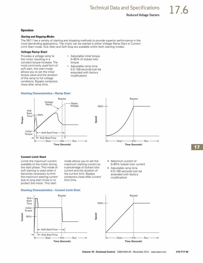
Volume 10—Enclosed Control CA08100012E—November 2012 www.eaton.com V10-T17-45
17
17
17
17
17
17
17
17
17
17
17
17
17
17
17
17
17
17
17
17
17
17
17
17
17
17
17
17
17
17
17.6Technical Data and Specifications
Reduced Voltage Starters
Operation
Starting and Stopping ModesThe S611 has a variety of starting and stopping methods to provide superior performance in the most demanding applications. The motor can be started in either Voltage Ramp Start or Current Limit Start mode. Kick Start and Soft Stop are available within both starting modes.
Voltage Ramp Start
Provides a voltage ramp to the motor resulting in a constant torque increase. The most commonly used form of soft start, this start mode allows you to set the initial torque value and the duration of the ramp to full voltage conditions. Bypass contactors close after ramp time.
● Adjustable initial torque 0–85% of locked rotor torque
● Adjustable ramp time 0.5–180 seconds (can be extended with factory modification)
Starting Characteristics—Ramp Start
Current Limit Start
Limits the maximum current available to the motor during the start phase. This mode of soft starting is used when it becomes necessary to limit the maximum starting current due to long start times or to protect the motor. This start
mode allows you to set the maximum starting current as a percentage of locked rotor current and the duration of the current limit. Bypass contactors close after current limit time.
● Maximum current of 0–85% locked rotor current
● Adjustable ramp time 0.5–180 seconds (can be extended with factory modification)
Starting Characteristics—Current Limit Start
InitialTorque
KickStartTorq
Kick Start Time
100%
Bypass BypassVoltageRamp Rated
Voltage
Soft Start Time
trStart Run
To
rqu
e
Time (Seconds)
100%
Start Run
Sp
ee
d
Time (Seconds)
InitialTorque
KickStartTorq
Kick Start Time
100%
Bypass Bypass
Soft Start Time
Start Run
Cu
rre
nt
Time (Seconds) Time (Seconds)
100%
Start Run
Sp
ee
d

V10-T17-46 Volume 10—Enclosed Control CA08100012E—November 2012 www.eaton.com
17
17
17
17
17
17
17
17
17
17
17
17
17
17
17
17
17
17
17
17
17
17
17
17
17
17
17
17
17
17
17.6 Technical Data and Specifications
Reduced Voltage Starters
Kick Start
Selectable feature in both Voltage Ramp Start and Current Limit Start modes. Provides a current and torque “kick” for 0 to 2.0 seconds. This provides greater initial current to develop additional torque to breakaway a high friction load.
● 0–85% of locked rotor torque
● 0–2.0 seconds duration
Starting Characteristics—Kick Start
Soft Stop
Allows for a controlled stopping of a load. Used when a stop-time that is greater than the coast-to-stop time is desired. Often used with high friction loads where a sudden stop may cause system or load damage.
● Stop time = 0–60 seconds
Starting Characteristics—Soft Stop
100%
Lo
cked
Ro
tor To
rqu
e
Ramp
Time (Seconds)
KickStart
Run
SoftStop Time
100%
Run Soft Stop
Sp
ee
d
Time (Seconds)
Coast to Stop(Speed)
Soft Stop Ramp(Voltage)

Volume 10—Enclosed Control CA08100012E—November 2012 www.eaton.com V10-T17-47
17
17
17
17
17
17
17
17
17
17
17
17
17
17
17
17
17
17
17
17
17
17
17
17
17
17
17
17
17
17
17.6Technical Data and Specifications
Reduced Voltage Starters
Pump Control Option
This option is intended to reduce the potential for water hammer in a centrifugal pump system by using a starting and stopping algorithm developed for pump control. Upon a start command, the speed of the motor is
increased, under the control of the S611 soft starter microprocessor, to achieve a gentle start. After the speed has reached its nominal value, the bypass contactors close and the pump operates as with any other starter.
Upon a stop command, the bypass contactors are opened and the motor speed is decreased in a tapered manner, to gradually slow the flow until the motor is brought to a stop.
Pump Control Option
Edge and Level Sensing ControlEdge or Level Sensing is selected with the Start Control parameter in the Advanced Configuration Menu. Factory default is Level Sensing.
Edge Sensing
Edge sensing requires 120 Vac power be momentarily applied to the Start terminal (with the Permissive terminal 120 Vac) to initiate a start under all conditions. After a stop or fault occurs, the 120 Vac must be reapplied to the start terminal before another start can occur. This control configuration should be used when restarting of the motor after a fault or stop must be supervised manually or as a part of a control scheme. The cycling of 120 Vac power to the Permissive terminal before starting is required regardless of the position of the auto reset parameter.
Level Sensing
Level sensing will enable a motor to restart after a fault is cleared without cycling 120V AC to the Permissive terminal as long as:
● Permissive terminal is supplied with 120 Vac
● The auto reset parameter is set to enabled
● All faults have cleared or have been reset
This control configuration should be used where it is desirable to restart a motor after a fault without additional manual or automatic control. An example of this condition would be on a remote pumping station where it is desirable to automatically restart a pump after a power outage without operator intervention.
Note: If the auto reset feature is used, CAUTION must be exercised to assure that any restart occurs in a safe manner.
100%
tr
potS pmuP tfoStratS
Sp
ee
d
Time (Seconds)
ts
Run
Coast to Stop
V10-T17-48 Volume 10—Enclosed Control CA08100012E—November 2012 www.eaton.com
17
17
17
17
17
17
17
17
17
17
17
17
17
17
17
17
17
17
17
17
17
17
17
17
17
17
17
17
17
17
17.6 Technical Data and Specifications
Reduced Voltage Starters
Features and Benefits● The User Interface Module
(UI) provides an intuitive, easy-to-use human interface with powerful configuration capabilities to maximize system performance
● Door or device mounted UI enables users to safely configure, commission, monitor and troubleshoot the system at the electrical panel without opening the enclosure door, eliminating the possibility of an arc flash incident
● System operating parameters can be monitored enterprise-wide through a communications network. Increase uptime by providing data for process management and preventive diagnostics
● Run bypass mode greatly reduces internal heating created by the greater power dissipation in the SCRs. Bypass contactors directly connect the motor to the line and improves system efficiency by reducing internal power losses
● Internal solid-state overload protection provides accurate current measurement and trip settings. Sophisticated algorithms solve a series of differential equations that model true motor heating and cooling, resulting in superior motor overload protection while minimizing nuisance trips. Advanced selectable protective features safeguard the motor and system against a variety of system faults
● Internal run bypass contactors and overload protection eliminate the need for additional devices, reducing enclosure sizes minimizing installation and wiring time and reducing overall assembly size and cost
● Wide range of overload FLA settings (50–100% of rated frame current) and a selectable trip class (5–30) offers users the flexibility to fine tune the starter to match specific application requirements
● Variable ramp times and torque control settings provide unlimited starting configurations, allowing for maximum application flexibility
● Kick-start feature enables soft starting of high friction loads
● Soft stop control for applications where an abrupt stop of the load is not acceptable
● Pump control option with sophisticated pump algorithms on both starting and stopping that minimize the pressure surges that cause water hammer. The pump control option will maximize the life of the pump and piping systems while minimizing the downtime caused by system failure
● Six SCRs control all three motor phases, providing smooth acceleration and deceleration performance
● Soft acceleration and deceleration reduces wear on belts, gears, chains, clutches, shafts and bearings
● Reduce the peak inrush current's stress on the power system
● Minimize peak starting torque to diminish mechanical system wear and damage
● 120 Vac control voltage enhances ease of connections
● The S611 lends itself to serviceability. The PCBs and contactors can be replaced in the field
Protective FeaturesAll protective features can be configured, enabled or disabled with the UI or through the communications network.
Motor Overload
The S611 includes electronic overload protection as standard. The overload meets applicable requirements for a motor overload protective device. The overload protects the motor from over heat conditions with the use of sophisticated algorithms that model true motor heating, resulting in superior motor protection and fewer nuisance trips.
The S611 calculates a thermal memory value. A 100% value represents the maximum safe temperature of the motor. When the thermal memory value reaches 100%, an overload trip will occur removing power to the motor.
Upon trip, the S611 stores the calculated motor heating value and will not allow a motor re-start until the motor has cooled. This feature ensures the motor will not be damaged by repeated overload trip, reset and re-start cycles.
The thermal memory value can be monitored through the UI or the communications network. The thermal memory value can be of great use in determining an impending overload trip condition. Alarms can be implemented in the process monitoring system warning of an impending trip before a trip occurs halting the process. Costly system downtime can be avoided.
The trip current is adjusted to match the specific application requirements by entering the motor nameplate full load current rating and trip class. The FLA adjustment includes a 2 to 1 adjustment range. The overload trip class is adjustable from class 5 through class 30. The overload is ambient temperature compensated - meaning its trip characteristics will not vary with changes in ambient temperature. The overload protection can be enabled, disabled, or disabled on start.
Short Circuit
The use of a short circuit protective device in coordination with the S611 is required in branch motor circuits by most electrical codes. Short circuit coordination ratings with both fuses and Eaton molded case circuit breakers are available providing customers with design flexibility. The S611 has short circuit coordination ratings as an open component, an enclosed starter, and in a motor control center. The short circuit ratings can go up to 100KA.

Volume 10—Enclosed Control CA08100012E—November 2012 www.eaton.com V10-T17-49
17
17
17
17
17
17
17
17
17
17
17
17
17
17
17
17
17
17
17
17
17
17
17
17
17
17
17
17
17
17
17.6Technical Data and Specifications
Reduced Voltage Starters
Jam
Excessive current and torque up to locked rotor levels can occur in a jam condition. The condition can result in stress and damage to the motor, load, mechanical system, and the electrical distribution system. Jam protection prevents the stress and damage from a jam during normal run. After the motor is started, a current greater than 300% FLA setting will cause the starter to trip on a jam fault.
Stall
Excessive current and torque up to locked rotor levels can occur in a stall condition. The condition can lead to an overload trip and result in stress and damage to the motor, load, mechanical system, and the electrical distribution system. Stall protection prevents stress and damage to a motor that has not come up to speed, or stalled after the soft start time. The S611 will trip to protect the system in the event that the motor did not get to the rated speed in the defined soft start period. A current greater than 200% FLA at the end of the soft start period will cause the starter to trip on a stall fault.
Pole Over Temperature
High ambient temperatures, extended ramp times and high duty cycle conditions may cause the S611 power pole conductors to reach a temperature that exceeds their thermal rating. The S611 is equipped with sensors that monitor the temperature of the power poles. Over temperature protection occurs if the device's thermal capacity is exceeded. The soft starter will trip in over temperature conditions, preventing device failure.
The device pole temperature value can be monitored through the UI or the communications network. This feature can be of use in determining an impending over temperature trip condition. Alarms can be implemented in the process monitoring system warning of an impending trip before a trip occurs, halting the process. Costly system shutdown can be avoided.
Phase Loss
Loss of a phase can cause a significant increase in the current drawn in the remaining two phases. Phase loss can lead to motor damage before an eventual overload trip occurs. Phase loss is typically an indication of a failure in the electrical distribution system. The S611 will detect a phase loss and trip if any phase current drops below a preset value. The phase loss trip level is adjustable from 0% to 100% of the average of the other two phase levels with an adjustable trip delay of 0.1 to 60 seconds.
Phase Imbalance
Phase current or voltage imbalance can cause a significant increase in the current drawn in the remaining two phases. Phase imbalance can lead to motor damage before an eventual overload trip. Phase imbalance is typically an indication of a failure in the electrical distribution system or the motor. The S611 will detect both current and voltage phase imbalances and trip if any phase becomes imbalanced as compared to the average of the other two phases.
The phase current imbalance trip level is adjustable from 0% to 100% of the average of the current in the other two phases with an adjustable trip delay of 0.1 to 60 seconds.
The phase voltage imbalance trip level is adjustable from 0% to 100% of the average of the voltage in the other two phases with an adjustable trip delay of 0.1 to 60 seconds.
Reset Mode
The S611 can be set up for automatic or manual reset on trip. The manual reset mode requires the operator to physically press the RESET button located on the soft starter. The overload can be manually reset through the UI or through the communications network.
The automatic reset mode allows the soft starter to be automatically reset as soon as the trip condition is no longer present. With the automatic reset mode, after the fault is no longer present, the motor will be restarted as soon as a valid start signal is present.
Phase Reversal
The S611 can determine if the proper line phase sequence is present by default. The device will trip if the line phase sequence is something other than A-B-C. The S611 can be configured to operate under reversed phase conditions (A-C-B).
Shorted SCR Detection
The S611 monitors the operation of the power poles and will trip under a shorted SCR condition.
Open SCR Detection
The S611 monitors the operation of the power poles and will trip under an open SCR condition.
Low Current
Low current conditions can be a result of a loss of load or a failure in the mechanical system. The S611 has low current protection that will trip if the average RMS current falls below a preset value. The low current protection can be programmed as a percent of motor FLA from 0% to 100%.
Low Voltage
Low voltage conditions can result from disturbances in the electrical power distribution system. Low voltage conditions can cause a malfunction and damage to electrical equipment. The S611 has low voltage protection that will trip if the average RMS voltage falls below a preset value. The low voltage protection can be programmed as a percent of nominal voltage from 1% to 99% with a trip delay of 0.1 to 60 seconds.
High Voltage
High voltage conditions can result from disturbances in the electrical power distribution system. High voltage conditions can cause malfunctions or failures of electrical equipment. The S611 has high voltage protection that will trip if the average RMS voltage is greater than a preset value. The high voltage protection can be programmed as a percent of nominal voltage from 101% to 120% with a trip delay of 0.1 to 60 seconds.

V10-T17-50 Volume 10—Enclosed Control CA08100012E—November 2012 www.eaton.com
17
17
17
17
17
17
17
17
17
17
17
17
17
17
17
17
17
17
17
17
17
17
17
17
17
17
17
17
17
17
17.6 Technical Data and Specifications
Reduced Voltage Starters
Monitoring CapabilitiesThe S611 has an impressive array of system monitoring capabilities that allow users to access real time process and diagnostic data. This data can be viewed at the device with the UI or through a communications network. Data over a communications network can provide valuable insight into the condition of the equipment and processes. Maintenance and production personnel can
monitor critical operational and maintenance data from a central control station that can be located far away from the production facility. Process data can be monitored to determine system anomalies that may indicate a need for preventive maintenance or an Impeding failure.
Adjustments made through the communications network can reduce costs by minimizing
the time traveling to the location where the motor controls are located. When faults do occur, real time fault data can assist maintenance in troubleshooting and planning repair resources. Remote reset signals can be given to tripped devices without the need for manual intervention by maintenance personnel.
Average Line Current
Provides the average of the three phase RMS line currents in amps, accurate to within 2%. Current data can be used to indicate a need for maintenance. Increased currents in a fixed load application can indicate a reduction in system efficiencies and performance, signifying system maintenance is due.
Average Pole Current
Provides the average of the three phase RMS pole currents in amps, accurate to within 2%. The pole current is the current through the soft starter. The line and pole current will be identical inin-line applications, and will differ in inside-the-delta applications.
Average Line Current as a % FLA
Provides the average RMS line current as a percentage of the S611 FLA setting.
Three-Phase Line Currents
Provides three RMS phase line currents in amps, accurate to within 2%. Imbalances or changes in the relative phase current to one another can indicate anomalies in the motor or electrical distribution system.
Three-Phase Pole Currents
Provides three RMS phase pole currents in amps, accurate to within 2%. The pole current is the current through the soft starter. The line and pole current will be identical in in-line applications.
Three-Phase Line Voltages
Provides the individual RMS three phase line voltages. Imbalances or changes in the relative phase voltage to one another can indicate anomalies in the motor or electrical distribution system. Voltage can be used to monitor electrical distribution system performance. Warnings, alarms and system actions to low or high voltage conditions can be implemented.
Percent Thermal Memory
Provides the real time calculated thermal memory value. The S611 calculates thermal memory value. A 100% value represents the maximum safe temperature of the motor. When the thermal memory value reaches 100%, an overload trip will occur, removing power to the motor.
The thermal memory value can be of great use in determining an impending overload trip Condition. Alarms can be implemented in the process monitoring system warning of an Impending trip before a trip occurs, halting the process. Costly system downtime can be avoided.
Pole Temperature
Increases in pole temperature are caused by increases in ambient temperature, start/stop times and start duty cycles. Changes in pole temperatures represent a change in system operating conditions. Identifying unexpected operating conditions or changes can prompt maintenance and aid in process evaluation activities.
Power Monitoring
S611 can monitor power and it can be displayed on the UI.
Start Count
Number of starts are stored in the device and can be displayed using field bus.

Volume 10—Enclosed Control CA08100012E—November 2012 www.eaton.com V10-T17-51
17
17
17
17
17
17
17
17
17
17
17
17
17
17
17
17
17
17
17
17
17
17
17
17
17
17
17
17
17
17
17.6Technical Data and Specifications
Reduced Voltage Starters
DiagnosticsFault Queue
Current fault and a fault queue containing the last nine system faults can be read through the UI or communications network. Fault identification can minimize troubleshooting time and cost and prevent arc flash incidents. The fault queue can be remotely accessed through a communications network to assist in planning maintenance resources. 30 different faults can be identified by the S611.
Control Status
The S611 provides data that represents system conditions that can be read through the UI or the communications network. This data identifies the status of the system and the control commands the system is requesting of the S611. This can be used for advanced Troubleshooting and system integration activities.
Field Serviceability
In the case of maintenance, the S611 provides easy access and replacement of key components including control board and internal bypass contactors—significantly increasing its service life. If a component ever needs to be replaced, this straightforward operation can be completed by an end-user without the need to call in an outside service technician or engineer. These components are stocked and available for order and quick fulfillment—ensuring your operation continues with minimal downtime.
Standards and Certifications● IEC 60947-4-2● UL listed ● CSA certified (3211 06)
Instructional Leaflets● Instruction Manual: MN03902011E● Quick Start Guide: MN03901003E

V10-T17-52 Volume 10—Enclosed Control CA08100012E—November 2012 www.eaton.com
17
17
17
17
17
17
17
17
17
17
17
17
17
17
17
17
17
17
17
17
17
17
17
17
17
17
17
17
17
17
17.6 Technical Data and Specifications
Reduced Voltage Starters
S801+/S811+ Solid-State Soft StartersFurnish as indicated Eaton Class ECS combination starters manufactured by Eaton’s electrical sector or approved equal. All starters shall be UL listed and conform to the latest IEC and NEMA Standards and the National Electric Code.
S801+ Soft Starter S811+ Soft Starter
General● All motor starters shall be
fully rated SCR devices up to 1000 amperes, with an adjustable ramp time up to 360 seconds as either current limit or torque, an initial torque kick start adjustable from 0–85% and soft stop adjustable up to 60 seconds
● Overload relays shall be solid-state and provide motor protection accuracy to 2%. Phase loss and phase unbalance protection shall be included as standard. The overload relay shall be heaterless and capable of selecting Class 10, 20 or 30 protection. Full-load current settings shall be set with dial settings or control interface module
● 24 Vdc power supplies are supplied as standard and are available with primary ratings from 480–120 Vac and have ratings available from 10–160 watts. Power supplies are equipped with a built-in short-circuit protection
● Control circuit transformers, where specified, shall be encapsulated. Primary and secondary fusing shall be provided. Unless otherwise specified, the secondary shall be 120 Vac. 100 VA is minimum
● Pilot devices, where specified, shall be oiltight and mounted in the flange. Pilot lights shall be transformer type for longer lamp life. Pilot device legend plates shall be engraved aluminum
● Running bypass contactor shall be supplied integral to the soft starter and capable of handling full load amperage
● Option available for full-voltage emergency bypass contactor
● S801+/S811+ shall have built-in communication port to enable control network connectivity
● S811+ shall have a removable digital interface module allowing access to monitor and adjust all parameters. DIM shall be an LCD display
● S801+ shall have a removable control interface module allowing adjustments to Class, FLA, ramp time, stop time, initial torque and protective features
Enclosure● Enclosures shall be Type 1,
3R, 4, 4X, 7/9 or 12, as scheduled
● The operating mechanism shall be mounted on the flange and shall have positive, non-teasing ON/OFF action. The handle shall be color-coded: red for ON and black for OFF
● The operating handle shall have a means to lock the handle in the OFF position with a minimum of three standard padlocks having 1/4 in diameter shackles
● The enclosure sub-panel shall be easily removed without disturbing the operating mechanism
● Enclosures shall have means for locking the cover
Short-Circuit Protective Device
Disconnect Switch● Where specified, a
disconnect switch with double break, rotary blades and quick make/quick break action shall be provided
● A line shield with test probe holes for inspection shall be provided. The shield shall be removable
● The switch shall have readily visible blades in the open (OFF) position
● The fusible disconnect switch (through 100A) shall have built-in fuse pullers to make it easier to remove fuses
Circuit Breaker● Where specified, an
adjustable instantaneous trip, magnetic only circuit breaker shall be provided
● A manual push-to-trip button shall be provided to exercise the trip unit
Short-Circuit Rating● Fusible disconnect
switches shall be UL listed for 100,000 amperes available when Class R fuses are used
● Combination starters with adjustable instantaneous trip, magnetic only circuit breakers shall be UL listed for 100,000 amperes available through 480 Vac
DescriptionCatalog Number
Non-combination ECS90
Disconnect switch ECS91
Circuit breaker ECS92
DescriptionCatalog Number
Non-combination ECS93
Disconnect switch ECS94
Circuit breaker ECS95

Volume 10—Enclosed Control CA08100012E—November 2012 www.eaton.com V10-T17-53
17
17
17
17
17
17
17
17
17
17
17
17
17
17
17
17
17
17
17
17
17
17
17
17
17
17
17
17
17
17
17.6Technical Data and Specifications
Reduced Voltage Starters
Technical Data and Specifications
Soft Starters—S801+
Description S801+N37N3S S801+N66N3S S801+R10N3S S801+R13N3S
Max. current capacity 37 66 105 135
General Information
Bypass mechanical lifespan 10M 10M 10M 10M
Insulating voltage Ui 660V 660V 660V 660V
Ramp time range 0.5–180 seconds 0.5–180 seconds 0.5–180 seconds 0.5–180 seconds
Resistance to vibration 3g 3g 3g 3g
Resistance to shock 15g 15g 15g 15g
Electrical Information
Operating voltage 200–600V 200–600V 200–600V 200–600V
Operating frequency 47–63 Hz 47–63 Hz 47–63 Hz 47–63 Hz
Overload setting 30–100% 30–100% 30–100% 30–100%
Trip class 5, 10, 20 and 30 5, 10, 20 and 30 5, 10, 20 and 30 5, 10, 20 and 30
Cabling Capacity (IEC 947)
Number of conductors 1 1 1 1
Wire sizes 14–2 14–2 14–4/0 14–4/0
Type of connectors Box lug Box lug Box lug Box lug
Control Wiring (12-Pin)
Wire sizes in AWG 22–14 22–14 22–14 22–14
Number of conductors (stranded) 2 (or one AWG 12) 2 (or one AWG 12) 2 (or one AWG 12) 2 (or one AWG 12)
Torque requirements in lb-in 3.5 3.5 3.5 3.5
Solid, stranded or flexible max. size in mm2 3.31 3.31 3.31 3.31
Control Power Requirements
Voltage range (24V ±10%) 21.6–26.4 21.6–26.4 21.6–26.4 21.6–26.4
Steady-state current amps 1.0 1.0 1.0 1.0
Inrush current amps 10 10 10 10
Ripple 1% 1% 1% 1%
Relays (1) Class A and C
Voltage AC—maximum 240 240 240 240
Voltage DC—maximum 120 120 120 120
Amps—maximum 3 3 3 3
Environment
Temperature—operating –30 to 50°C (no derating) consult factory for operation >50°C
–30 to 50°C (no derating) consult factory for operation >50°C
–30 to 50°C (no derating) consult factory for operation >50°C
–30 to 50°C (no derating) consult factory for operation >50°C
Temperature—storage –50 to 70°C –50 to 70°C –50 to 70°C –50 to 70°C
Altitude <2000m—consult factory for operation >2000m
<2000m—consult factory for operation >2000m
<2000m—consult factory for operation >2000m
<2000m—consult factoryfor operation >2000m
Humidity <95% noncondensing <95% noncondensing <95% noncondensing <95% noncondensing
Operating position Any Any Any Any
Pollution degree IEC947-1 3 3 3 3
Impulse withstand voltage IEC947-4-1 6000V 6000V 6000V 6000V

V10-T17-54 Volume 10—Enclosed Control CA08100012E—November 2012 www.eaton.com
17
17
17
17
17
17
17
17
17
17
17
17
17
17
17
17
17
17
17
17
17
17
17
17
17
17
17
17
17
17
17.6 Technical Data and Specifications
Reduced Voltage Starters
Soft Starters—S801+, continued
Notes1 801+U50N3S unit does not have IEC certification.2 UL recognized component.
Description S801+T18N3S S801+T24N3S S801+T30N3S S801+U36N3S 12
Max. current capacity 180 240 304 360
General Information
Bypass mechanical lifespan 10M 10M 10M 10M
Insulating voltage Ui 660V 660V 660V 660V
Ramp time range 0.5–180 seconds 0.5–180 seconds 0.5–180 seconds 0.5–180 seconds
Resistance to vibration 3g 3g 3g 3g
Resistance to shock 15g 15g 15g 15g
Electrical Information
Operating voltage 200–600V 200–600V 200–600V 200–600V
Operating frequency 47–63 Hz 47–63 Hz 47–63 Hz 47–63 Hz
Overload setting 30–100% 30–100% 30–100% 30–100%
Trip class 5, 10, 20 and 30 5, 10, 20 and 30 5, 10, 20 and 30 5, 10, 20 and 30
Cabling Capacity (IEC 947)
Number of conductors 1 or 2 1 or 2 1 or 2 1 or 2
Wire sizes 4 AWG to 500 kcmil 4 AWG to 500 kcmil 4 AWG to 500 kcmil 4 AWG to 500 kcmil
Type of connectors Add-on lug kit Add-on lug kit Add-on lug kit Add-on lug kit
Control Wiring (12-Pin)
Wire sizes in AWG 22–14 22–14 22–14 22–14
Number of conductors (stranded) 2 (or one AWG 12) 2 (or one AWG 12) 2 (or one AWG 12) 2 (or one AWG 12)
Torque requirements in lb-in 3.5 3.5 3.5 3.5
Solid, stranded or flexible max. size in mm2 3.31 3.31 3.31 3.31
Control Power Requirements
Voltage range (24V ±10%) 21.6–26.4 21.6–26.4 21.6–26.4 21.6–26.4
Steady-state current amps 1.0 1.0 1.0 1.0
Inrush current amps 10 10 10 10
Ripple 1% 1% 1% 1%
Relays (1) Class A and C
Voltage AC—maximum 240 240 240 240
Voltage DC—maximum 120 120 120 120
Amps—maximum 3 3 3 3
Environment
Temperature—operating –30 to 50°C (no derating) consult factory for operation >50°C
–30 to 50°C (no derating) consult factory for operation >50°C
–30 to 50°C (no derating) consult factory for operation >50°C
–30 to 50°C (no derating) consult factory for operation >50°C
Temperature—storage –50 to 70°C –50 to 70°C –50 to 70°C –50 to 70°C
Altitude <2000m—consult factory for operation >2000m
<2000m—consult factory for operation >2000m
<2000m—consult factory for operation >2000m
<2000m—consult factory for operation >2000m
Humidity <95% noncondensing <95% noncondensing <95% noncondensing <95% noncondensing
Operating position Any Any Any Any
Pollution degree IEC947-1 3 3 3 3
Impulse withstand voltage IEC947-4-1 6000V 6000V 6000V 6000V

Volume 10—Enclosed Control CA08100012E—November 2012 www.eaton.com V10-T17-55
17
17
17
17
17
17
17
17
17
17
17
17
17
17
17
17
17
17
17
17
17
17
17
17
17
17
17
17
17
17
17.6Technical Data and Specifications
Reduced Voltage Starters
Soft Starters—S801+, continued
Note1 801+U50N3S unit does not have IEC certification.
Description S801+U42N3S S801+U50N3S 1 S801+V36N3S S801+V42N3S
Max. current capacity 420 500 360 420
General Information
Bypass mechanical lifespan 10M 10M 10M 10M
Insulating voltage Ui 660V 660V 660V 660V
Ramp time range 0.5–180 seconds 0.5–180 seconds 0.5–180 seconds 0.5–180 seconds
Resistance to vibration 3g 3g 3g 3g
Resistance to shock 15g 15g 15g 15g
Electrical Information
Operating voltage 200–600V 200–600V 200–600V 200–600V
Operating frequency 47–63 Hz 47–63 Hz 47–63 Hz 47–63 Hz
Overload setting 30–100% 30–100% 30–100% 30–100%
Trip class 5, 10, 20 and 30 5, 10, 20 and 30 5, 10, 20 and 30 5, 10, 20 and 30
Cabling Capacity (IEC 947)
Number of conductors 1 or 2 1 or 2 2, 4 or 6 2, 4 or 6
Wire sizes 4 AWG to 500 kcmil 4 AWG to 500 kcmil 2/0 to 500 kcmil 2/0 to 500 kcmil
Type of connectors Add-on lug kit Add-on lug kit Add-on lug kit Add-on lug kit
Control Wiring (12-Pin)
Wire sizes in AWG 22–14 22–14 22–14 22–14
Number of conductors (stranded) 2 (or one AWG 12) 2 (or one AWG 12) 2 (or one AWG 12) 2 (or one AWG 12)
Torque requirements in lb-in 3.5 3.5 3.5 3.5
Solid, stranded or flexible max. size in mm2 3.31 3.31 3.31 3.31
Control Power Requirements
Voltage range (24V ±10%) 21.6–26.4 21.6–26.4 21.6–26.4 21.6–26.4
Steady-state current amps 1.0 1.0 1.4 1.4
Inrush current amps 10 10 10 10
Ripple 1% 1% 1% 1%
Relays (1) Class A and C
Voltage AC—maximum 240 240 240 240
Voltage DC—maximum 120 120 120 120
Amps—maximum 3 3 3 3
Environment
Temperature—operating –30 to 50°C (no derating) consult factory for operation >50°C
–30 to 50°C (no derating) consult factory for operation >50°C
–30 to 50°C (no derating) consult factory for operation >50°C
–30 to 50°C (no derating) consult factory for operation >50°C
Temperature—storage –50 to 70°C –50 to 70°C –50 to 70°C –50 to 70°C
Altitude <2000m—consult factory for operation >2000m
<2000m—consult factory for operation >2000m
<2000m—consult factory for operation >2000m
<2000m—consult factory for operation >2000m
Humidity <95% noncondensing <95% noncondensing <95% noncondensing <95% noncondensing
Operating position Any Any Any Any
Pollution degree IEC947-1 3 3 3 3
Impulse withstand voltage IEC947-4-1 6000V 6000V 6000V 6000V

V10-T17-56 Volume 10—Enclosed Control CA08100012E—November 2012 www.eaton.com
17
17
17
17
17
17
17
17
17
17
17
17
17
17
17
17
17
17
17
17
17
17
17
17
17
17
17
17
17
17
17.6 Technical Data and Specifications
Reduced Voltage Starters
Soft Starters—S801+, continued
Note1 UL recognized component.
Description S801+V50N3S S801+V65N3S S801+V72N3S S801+V85N3S S801+V10N3S 1
Max. current capacity 500 650 720 850 1000
Dimensions
Width in inches (mm) 11.03 (280.2) 11.03 (280.2) 11.03 (280.2) 11.03 (280.2) 11.03 (280.2)
Height in inches (mm) 16.57 (420.8) 16.57 (420.8) 16.57 (420.8) 16.57 (420.8) 16.57 (420.8)
Depth in inches (mm) 7.23 (183.7) 7.23 (183.7) 7.23 (183.7) 7.23 (183.7) 7.23 (183.7)
Weight in lbs (kg) 103 (46.8) with lugs91 (41.4) without lugs
103 (46.8) with lugs91 (41.4) without lugs
103 (46.8) with lugs91 (41.4) without lugs
103 (46.8) with lugs91 (41.4) without lugs
103 (46.8) with lugs91 (41.4) without lugs
General Information
Bypass mechanical lifespan 10M 10M 10M 10M 10M
Insulating voltage Ui 660V 660V 660V 660V 660V
Ramp time range 0.5–180 seconds 0.5–180 seconds 0.5–180 seconds 0.5–180 seconds 0.5–180 seconds
Resistance to vibration 3g 3g 3g 3g 3g
Resistance to shock 15g 15g 15g 15g 15g
Electrical Information
Operating voltage 200–600V 200–600V 200–600V 200–600V 200–600V
Operating frequency 47–63 Hz 47–63 Hz 47–63 Hz 47–63 Hz 47–63 Hz
Overload setting 30–100% 30–100% 30–100% 30–100% 30–100%
Trip class 5, 10, 20 and 30 5, 10, 20 and 30 5, 10, 20 and 30 5, 10, 20 and 30 5, 10, 20 and 30
Cabling Capacity (IEC 947)
Number of conductors 2, 4 or 6 2, 4 or 6 2, 4 or 6 2, 4 or 6 2, 4 or 6
Wire sizes 2/0 to 500 kcmil 2/0 to 500 kcmil 2/0 to 500 kcmil 2/0 to 500 kcmil 2/0 to 500 kcmil
Type of connectors Add-on lug kit Add-on lug kit Add-on lug kit Add-on lug kit Add-on lug kit
Control Wiring (12-Pin)
Wire sizes in AWG 22–14 22–14 22–14 22–14 22–14
Number of conductors (stranded) 2 (or one AWG 12) 2 (or one AWG 12) 2 (or one AWG 12) 2 (or one AWG 12) 2 (or one AWG 12)
Torque requirements in lb-in 3.5 3.5 3.5 3.5 3.5
Solid, stranded or flexible max. size in mm2 3.31 3.31 3.31 3.31 3.31
Control Power Requirements
Voltage range (24V ±10%) 21.6–26.4 21.6–26.4 21.6–26.4 21.6–26.4 21.6–26.4
Steady-state current amps 1.4 1.4 1.4 1.4 1.4
Inrush current amps 10 10 10 10 10
Ripple 1% 1% 1% 1% 1%
Relays (1) Class A and C
Voltage AC—maximum 240 240 240 240 240
Voltage DC—maximum 120 120 120 120 120
Amps—maximum 3 3 3 3 3
Environment
Temperature—operating –30 to 50°C (no derating) consult factory for operation >50°C
–30 to 50°C (no derating) consult factory for operation >50°C
–30 to 50°C (no derating) consult factory for operation >50°C
–30 to 50°C (no derating) consult factory for operation >50°C
–30 to 50°C (no derating) consult factory for operation >50°C
Temperature—storage –50 to 70°C –50 to 70°C –50 to 70°C –50 to 70°C –50 to 70°C
Altitude <2000m—consult factory for operation >2000m
<2000m—consult factory for operation >2000m
<2000m—consult factory for operation >2000m
<2000m—consult factory for operation >2000m
<2000m—consult factory for operation >2000m
Humidity <95% noncondensing <95% noncondensing <95% noncondensing <95% noncondensing <95% noncondensing
Operating position Any Any Any Any Any
Pollution degree IEC947-1 3 3 3 3 3
Impulse withstand voltage IEC947-4-1 6000V 6000V 6000V 6000V 6000V

Volume 10—Enclosed Control CA08100012E—November 2012 www.eaton.com V10-T17-57
17
17
17
17
17
17
17
17
17
17
17
17
17
17
17
17
17
17
17
17
17
17
17
17
17
17
17
17
17
17
17.6Technical Data and Specifications
Reduced Voltage Starters
Wiring Diagrams
Line Connected Soft Starter
DimensionsApproximate Dimensions in Inches (mm)
Soft Starters—S801+
Catalog Number W H D
Weightin Lbs (kg)
S801+N37N3S 2.66 (67.6) 7.37 (187.2) 6.45 (163.9) 5.8 (2.6)
S801+N66N3S 2.66 (67.6) 7.37 (187.2) 6.45 (163.9) 5.8 (2.6)
S801+R10N3S 4.38 (111.3) 7.92 (201.1) 6.64 (168.6) 10.5 (4.8)
S801+R13N3S 4.38 (111.3) 7.92 (201.1) 6.64 (168.6) 10.5 (4.8)
S801+T18N3S 7.65 (194.4) 12.71 (322.9) 6.47 (164.4) 48 (21.8) with lugs 41 (18.6) without lugs
S801+T24N3S 7.65 (194.4) 12.71 (322.9) 6.47 (164.4) 48 (21.8) with lugs 41 (18.6) without lugs
S801+T30N3S 7.65 (194.4) 12.71 (322.9) 6.47 (164.4) 48 (21.8) with lugs 41 (18.6) without lugs
S801+U36N3S 7.73 (196.3) 12.72 (323.1) 7.16 (181.8) 48 (21.8) with lugs 41 (18.6) without lugs
S801+U42N3S 7.73 (196.3) 12.72 (323.1) 7.16 (181.8) 48 (21.8) with lugs 41 (18.6) without lugs
S801+U50N3S 7.73 (196.3) 12.72 (323.1) 7.16 (181.8) 48 (21.8) with lugs 41 (18.6) without lugs
S801+V36N3S 11.05 (280.6) 16.57 (420.8) 7.39 (187.8) 103 (46.8) with lugs 91 (41.4) without lugs
S801+V42N3S 11.05 (280.6) 16.57 (420.8) 7.39 (187.8) 103 (46.8) with lugs 91 (41.4) without lugs
S801+V50N3S 11.05 (280.6) 16.57 (420.8) 7.39 (187.8) 103 (46.8) with lugs 91 (41.4) without lugs
S801+V65N3S 11.05 (280.6) 16.57 (420.8) 7.39 (187.8) 103 (46.8) with lugs 91 (41.4) without lugs
S801+V72N3S 11.05 (280.6) 16.57 (420.8) 7.39 (187.8) 103 (46.8) with lugs 91 (41.4) without lugs
S801+V85N3S 11.05 (280.6) 16.57 (420.8) 7.39 (187.8) 103 (46.8) with lugs 91 (41.4) without lugs
S801+V10N3S 11.05 (280.6) 16.57 (420.8) 7.39 (187.8) 103 (46.8) with lugs 91 (41.4) without lugs
1 L1 3 L2 5 L3
2 T1 4 T2 6 T3
3~
M

V10-T17-58 Volume 10—Enclosed Control CA08100012E—November 2012 www.eaton.com
17
17
17
17
17
17
17
17
17
17
17
17
17
17
17
17
17
17
17
17
17
17
17
17
17
17
17
17
17
17
17.6 Technical Data and Specifications
Reduced Voltage Starters
Operation
Overload Functionality
OvertemperatureProtects the device from overheating. Starter will shut down at 100°C.
StallSelectable protective feature, unit trips to protect system in event motor can not get to rated speed in the defined ramp period.
JamSelectable protective feature, unit trips to prevent damage to motor during normal run.
Phase LossSelectable protective feature, trips under voltage loss condition to any phase.
Phase ReversalSelectable protective feature, trips when phase rotation is something other than A-B-C.
Kick StartSelectable feature that provides a current “kick” of up to 550% of full load current for 0 to 2.0 seconds. This provides the additional torque required at startup to break free a motor.
Ramp StartProvides a constant increase in torque to the motor.
Current Limit StartLimits the maximum current available to the motor during the startup phase.
Soft StopAllows for a controlled stopping of a frictional load.
Shorted SCR DetectionMonitors for shorted SCR in the power poles.
Starting Characteristics
Kick StartProvides an initial boost of current to the motor to help overcome motor inertia and begin motor rotation.
● 0–85% of locked rotor torque
● 0–2.0 seconds duration
Starting Characteristics—Kick Start
Ramp StartThe most commonly used form of soft start. This allows you to set the initial torque value (of the ramp) and then raises it to full voltage conditions.
● Adjustable initial torque = 0–85% of locked rotor torque
● Adjustable ramp time = 0.5–180 seconds
Starting Characteristics—Ramp Start
100%
Lo
cked
Ro
tor To
rqu
e
Ramp
Time (Seconds)
KickStart
Run
Run
100%
Lo
cke
d R
oto
r To
rqu
e
Time (Seconds)
InitialTorque

Volume 10—Enclosed Control CA08100012E—November 2012 www.eaton.com V10-T17-59
17
17
17
17
17
17
17
17
17
17
17
17
17
17
17
17
17
17
17
17
17
17
17
17
17
17
17
17
17
17
17.6Technical Data and Specifications
Reduced Voltage Starters
Current LimitThis mode of soft starting is used when it becomes necessary to limit the maximum starting current due to long start times or to protect the motor.
● Maximum current of 0–85% locked rotor current
● Adjustable ramp time = 0.5–180 seconds
Starting Characteristics—Current Limit
Soft StopUsed when an extended coast-to-rest period is desired. Often used with high friction loads where a sudden stop may cause system or product damage.
● Stop time = 0–60 seconds
Starting Characteristics—Soft Stop
Run
Max.Allowed
100%FLA
Cu
rre
nt
Time (Seconds)
Ramp
Time (Seconds)
Run

V10-T17-60 Volume 10—Enclosed Control CA08100012E—November 2012 www.eaton.com
17
17
17
17
17
17
17
17
17
17
17
17
17
17
17
17
17
17
17
17
17
17
17
17
17
17
17
17
17
17
17.6 Technical Data and Specifications
Reduced Voltage Starters
Technical Data and Specifications
Soft Starters—S811+
Description S811+N37_ S811+N66_ S811+R10+ S811+R13_
Max. current capacity 37 66 105 135
FLA range 11–37 20–66 32–105 42–135
General Information
Bypass mechanical lifespan 10M 10M 10M 10M
Insulating voltage Ui 660V 660V 660V 660V
Ramp time range 0.5–180 seconds (0.5–360 seconds S811+ Premium)
0.5–180 seconds (0.5–360 seconds S811+ Premium)
0.5–180 seconds (0.5–360 seconds S811+ Premium)
0.5–180 seconds (0.5–360 seconds S811+ Premium)
Resistance to vibration 3g 3g 3g 3g
Resistance to shock 15g 15g 15g 15g
Electrical Information
Operating voltage 200–600V 200–600V 200–600V 200–600V
Operating frequency 47–63 Hz 47–63 Hz 47–63 Hz 47–63 Hz
Overload setting 30–100% 30–100% 30–100% 30–100%
Trip class 5, 10, 20 and 30 5, 10, 20 and 30 5, 10, 20 and 30 5, 10, 20 and 30
Cabling Capacity (IEC 947)
Number of conductors 1 1 1 1
Wire sizes 14–2 14–2 14–4/0 14–4/0
Type of connectors Box lug Box lug Box lug Box lug
Control Wiring (12-Pin)
Wire sizes in AWG 22–14 22–14 22–14 22–14
Number of conductors (stranded) 2 (or one AWG 12) 2 (or one AWG 12) 2 (or one AWG 12) 2 (or one AWG 12)
Torque requirements in lb-in 3.5 3.5 3.5 3.5
Solid, stranded or flexible max. size in mm2 3.31 3.31 3.31 3.31
Control Power Requirements
Voltage range (24V ±10%) 21.6–26.4 21.6–26.4 21.6–26.4 21.6–26.4
Steady-state current amps 1.0 1.0 1.0 1.0
Inrush current amps 10 10 10 10
Ripple 1% 1% 1% 1%
Relays (1) Class A and C
Voltage AC—maximum 240 240 240 240
Voltage DC—maximum 120 120 120 120
Amps—maximum 3 3 3 3
Environment
Temperature—operating –30 to 50°C (no derating) consult factory for operation >50°C
–30 to 50°C (no derating) consult factory for operation >50°C
–30 to 50°C (no derating) consult factory for operation >50°C
–30 to 50°C (no derating) consult factory for operation >50°C
Temperature—storage –50 to 70°C –50 to 70°C –50 to 70°C –50 to 70°C
Altitude <2000m—consult factory for operation >2000m
<2000m—consult factory for operation >2000m
<2000m—consult factory for operation >2000m
<2000m—consult factory for operation >2000m
Humidity <95% noncondensing <95% noncondensing <95% noncondensing <95% noncondensing
Operating position Any Any Any Any
Pollution degree IEC947-1 3 3 3 3
Impulse withstand voltage IEC947-4-1 6000V 6000V 6000V 6000V
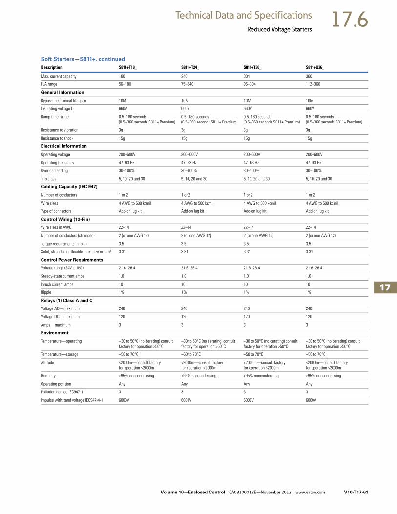
Volume 10—Enclosed Control CA08100012E—November 2012 www.eaton.com V10-T17-61
17
17
17
17
17
17
17
17
17
17
17
17
17
17
17
17
17
17
17
17
17
17
17
17
17
17
17
17
17
17
17.6Technical Data and Specifications
Reduced Voltage Starters
Soft Starters—S811+, continued
Description S811+T18_ S811+T24_ S811+T30_ S811+U36_
Max. current capacity 180 240 304 360
FLA range 56–180 75–240 95–304 112–360
General Information
Bypass mechanical lifespan 10M 10M 10M 10M
Insulating voltage Ui 660V 660V 660V 660V
Ramp time range 0.5–180 seconds (0.5–360 seconds S811+ Premium)
0.5–180 seconds (0.5–360 seconds S811+ Premium)
0.5–180 seconds (0.5–360 seconds S811+ Premium)
0.5–180 seconds (0.5–360 seconds S811+ Premium)
Resistance to vibration 3g 3g 3g 3g
Resistance to shock 15g 15g 15g 15g
Electrical Information
Operating voltage 200–600V 200–600V 200–600V 200–600V
Operating frequency 47–63 Hz 47–63 Hz 47–63 Hz 47–63 Hz
Overload setting 30–100% 30–100% 30–100% 30–100%
Trip class 5, 10, 20 and 30 5, 10, 20 and 30 5, 10, 20 and 30 5, 10, 20 and 30
Cabling Capacity (IEC 947)
Number of conductors 1 or 2 1 or 2 1 or 2 1 or 2
Wire sizes 4 AWG to 500 kcmil 4 AWG to 500 kcmil 4 AWG to 500 kcmil 4 AWG to 500 kcmil
Type of connectors Add-on lug kit Add-on lug kit Add-on lug kit Add-on lug kit
Control Wiring (12-Pin)
Wire sizes in AWG 22–14 22–14 22–14 22–14
Number of conductors (stranded) 2 (or one AWG 12) 2 (or one AWG 12) 2 (or one AWG 12) 2 (or one AWG 12)
Torque requirements in lb-in 3.5 3.5 3.5 3.5
Solid, stranded or flexible max. size in mm2 3.31 3.31 3.31 3.31
Control Power Requirements
Voltage range (24V ±10%) 21.6–26.4 21.6–26.4 21.6–26.4 21.6–26.4
Steady-state current amps 1.0 1.0 1.0 1.0
Inrush current amps 10 10 10 10
Ripple 1% 1% 1% 1%
Relays (1) Class A and C
Voltage AC—maximum 240 240 240 240
Voltage DC—maximum 120 120 120 120
Amps—maximum 3 3 3 3
Environment
Temperature—operating –30 to 50°C (no derating) consult factory for operation >50°C
–30 to 50°C (no derating) consult factory for operation >50°C
–30 to 50°C (no derating) consult factory for operation >50°C
–30 to 50°C (no derating) consult factory for operation >50°C
Temperature—storage –50 to 70°C –50 to 70°C –50 to 70°C –50 to 70°C
Altitude <2000m—consult factory for operation >2000m
<2000m—consult factory for operation >2000m
<2000m—consult factory for operation >2000m
<2000m—consult factory for operation >2000m
Humidity <95% noncondensing <95% noncondensing <95% noncondensing <95% noncondensing
Operating position Any Any Any Any
Pollution degree IEC947-1 3 3 3 3
Impulse withstand voltage IEC947-4-1 6000V 6000V 6000V 6000V

V10-T17-62 Volume 10—Enclosed Control CA08100012E—November 2012 www.eaton.com
17
17
17
17
17
17
17
17
17
17
17
17
17
17
17
17
17
17
17
17
17
17
17
17
17
17
17
17
17
17
17.6 Technical Data and Specifications
Reduced Voltage Starters
Soft Starters—S811+, continued
Note1 S811+U50_ unit does not have IEC certification.
Description S811+U42_ S811+U50_ 1 S811+V36_ S811+V42_
Max. current capacity 420 500 360 420
FLA range 131–420 156–500 112–360 131–420
General Information
Bypass mechanical lifespan 10M 10M 10M 10M
Insulating voltage Ui 660V 660V 660V 660V
Ramp time range 0.5–180 seconds (0.5–360 seconds S811+ Premium)
0.5–180 seconds (0.5–360 seconds S811+ Premium)
0.5–180 seconds (0.5–360 seconds S811+ Premium)
0.5–180 seconds (0.5–360 seconds S811+ Premium)
Resistance to vibration 3g 3g 3g 3g
Resistance to shock 15g 15g 15g 15g
Electrical Information
Operating voltage 200–600V 200–600V 200–600V 200–600V
Operating frequency 47–63 Hz 47–63 Hz 47–63 Hz 47–63 Hz
Overload setting 30–100% 30–100% 30–100% 30–100%
Trip class 5, 10, 20 and 30 5, 10, 20 and 30 5, 10, 20 and 30 5, 10, 20 and 30
Cabling Capacity (IEC 947)
Number of conductors 1 or 2 1 or 2 2, 4 or 6 2, 4 or 6
Wire sizes 4 AWG to 500 kcmil 4 AWG to 500 kcmil 4 AWG to 500 kcmil 4 AWG to 500 kcmil
Type of connectors Add-on lug kit Add-on lug kit Add-on lug kit Add-on lug kit
Control Wiring (12-Pin)
Wire sizes in AWG 22–14 22–14 22–14 22–14
Number of conductors (stranded) 2 (or one AWG 12) 2 (or one AWG 12) 2 (or one AWG 12) 2 (or one AWG 12)
Torque requirements in lb-in 3.5 3.5 3.5 3.5
Solid, stranded or flexible max. size in mm2 3.31 3.31 3.31 3.31
Control Power Requirements
Voltage range (24V ±10%) 21.6–26.4 21.6–26.4 21.6–26.4 21.6–26.4
Steady-state current amps 1.0 1.0 1.4 1.4
Inrush current amps 10 10 10 10
Ripple 1% 1% 1% 1%
Relays (1) Class A and C
Voltage AC—maximum 240 240 240 240
Voltage DC—maximum 120 120 120 120
Amps—maximum 3 3 3 3
Environment
Temperature—operating –30 to 50°C (no derating) consult factory for operation >50°C
–30 to 50°C (no derating) consult factory for operation >50°C
–30 to 50°C (no derating) consult factory for operation >50°C
–30 to 50°C (no derating) consult factory for operation >50°C
Temperature—storage –50 to 70°C –50 to 70°C –50 to 70°C –50 to 70°C
Altitude <2000m—consult factory for operation >2000m
<2000m—consult factory for operation >2000m
<2000m—consult factory for operation >2000m
<2000m—consult factory for operation >2000m
Humidity <95% noncondensing <95% noncondensing <95% noncondensing <95% noncondensing
Operating position Any Any Any Any
Pollution degree IEC947-1 3 3 3 3
Impulse withstand voltage IEC947-4-1 6000V 6000V 6000V 6000V

Volume 10—Enclosed Control CA08100012E—November 2012 www.eaton.com V10-T17-63
17
17
17
17
17
17
17
17
17
17
17
17
17
17
17
17
17
17
17
17
17
17
17
17
17
17
17
17
17
17
17.6Technical Data and Specifications
Reduced Voltage Starters
Soft Starters—S811+, continued
Note1 UR recognized product.
Description S811+V50_ S811+V65_ S811+V72_ S811+V85_ S811+V10_ 1
Max. current capacity 500 650 720 850 1000
FLA range 156–500 203–650 225–720 265–580 320–1000
General Information
Bypass mechanical lifespan 10M 10M 10M 10M 10M
Insulating voltage Ui 660V 660V 660V 660V 660V
Ramp time range 0.5–180 seconds (0.5–360 seconds S811+ Premium)
0.5–180 seconds (0.5–360 seconds S811+ Premium)
0.5–180 seconds (0.5–360 seconds S811+ Premium)
0.5–180 seconds (0.5–360 seconds S811+ Premium)
0.5–180 seconds (0.5–360 seconds S811+ Premium)
Resistance to vibration 3g 3g 3g 3g 3g
Resistance to shock 15g 15g 15g 15g 15g
Electrical Information
Operating voltage 200–600V 200–600V 200–600V 200–600V 200–600V
Operating frequency 47–63 Hz 47–63 Hz 47–63 Hz 47–63 Hz 47–63 Hz
Overload setting 30–100% 30–100% 30–100% 30–100% 30–100%
Trip class 5, 10, 20 and 30 5, 10, 20 and 30 5, 10, 20 and 30 5, 10, 20 and 30 5, 10, 20 and 30
Cabling Capacity (IEC 947)
Number of conductors 2, 4 or 6 2, 4 or 6 2, 4 or 6 2, 4 or 6 2, 4 or 6
Wire sizes 2/0 to 500 kcmil 2/0 to 500 kcmil 2/0 to 500 kcmil 2/0 to 500 kcmil 2/0 to 500 kcmil
Type of connectors Add-on lug kit Add-on lug kit Add-on lug kit Add-on lug kit Add-on lug kit
Control Wiring (12-Pin)
Wire sizes in AWG 22–14 22–14 22–14 22–14 22–14
Number of conductors (stranded) 2 (or one AWG 12) 2 (or one AWG 12) 2 (or one AWG 12) 2 (or one AWG 12) 2 (or one AWG 12)
Torque requirements in lb-in 3.5 3.5 3.5 3.5 3.5
Solid, stranded or flexible max. size in mm2 3.31 3.31 3.31 3.31 3.31
Control Power Requirements
Voltage range (24V ±10%) 21.6–26.4 21.6–26.4 21.6–26.4 21.6–26.4 21.6–26.4
Steady-state current amps 1.4 1.4 1.4 1.4 1.4
Inrush current amps 10 10 10 10 10
Ripple 1% 1% 1% 1% 1%
Relays (1) Class A and C
Voltage AC—maximum 240 240 240 240 240
Voltage DC—maximum 120 120 120 120 120
Amps—maximum 3 3 3 3 3
Environment
Temperature—operating –30 to 50°C (no derating) consult factory for operation >50°C
–30 to 50°C (no derating) consult factory for operation >50°C
–30 to 50°C (no derating) consult factory for operation >50°C
–30 to 50°C (no derating) consult factory for operation >50°C
–30 to 50°C (no derating) consult factory for operation >50°C
Temperature—storage –50 to 70°C –50 to 70°C –50 to 70°C –50 to 70°C –50 to 70°C
Altitude <2000m—consult factory for operation >2000m
<2000m—consult factory for operation >2000m
<2000m—consult factory for operation >2000m
<2000m—consult factory for operation >2000m
<2000m—consult factory for operation >2000m
Humidity <95% noncondensing <95% noncondensing <95% noncondensing <95% noncondensing <95% noncondensing
Operating position Any Any Any Any Any
Pollution degree IEC947-1 3 3 3 3 3
Impulse withstand voltage IEC947-4-1 6000V 6000V 6000V 6000V 6000V

V10-T17-64 Volume 10—Enclosed Control CA08100012E—November 2012 www.eaton.com
17
17
17
17
17
17
17
17
17
17
17
17
17
17
17
17
17
17
17
17
17
17
17
17
17
17
17
17
17
17
17.6 Technical Data and Specifications
Reduced Voltage Starters
Wiring Diagrams
Line Connected Soft Starter
Inside-the-Delta Connected Soft Starter for a 6-Lead Motor
Inside-the-Delta Connected Soft Starter for a 12-Lead Low Voltage Motor
Inside-the-Delta Connected Soft Starter for a 12-Lead High Voltage Motor
1 L1 3 L2 5 L3
2 T1 4 T2 6 T3
3~
M
L1S L2S
Supply
L3S
L31L1
3L2
5L3
T5 T4 T6
T3
T3
T3
T6
T4
T1T1
T2
T2
T2
T1
2T1
4T2
6T3
T5
L1
L1
Motor
L3
L2L2
S811+
L1S L2S
Supply
L3S
L3
L1
1L1
3L2
5L3
T11T5
T11T10T4
T12T6
T3T9
T3
T5
T3
T6T10
T7
T4
T1
T1
T12
T9
T2T8
T2
T2
T1T7
2T1
4T2
6T3
T8
L1
Motor
L3
L2L2
12-LeadLow Voltage
S811+
L1S L2S
Supply 12-LeadHigh VoltageL3S
L3
L1
1L1
3L2
5L3
T11
T11
T10 T12
T3
T3
T3
T6T10
T7
T4T1
T1
T12
T9
T2
T2
T2
T1
2T1
4T2
6T3
T8T5
T5T8
T6T9
L1
T7T4
Motor
L3
L2L2
S811+

Volume 10—Enclosed Control CA08100012E—November 2012 www.eaton.com V10-T17-65
17
17
17
17
17
17
17
17
17
17
17
17
17
17
17
17
17
17
17
17
17
17
17
17
17
17
17
17
17
17
17.6Technical Data and Specifications
Reduced Voltage Starters
DimensionsApproximate Dimensions in Inches (mm)
Soft Starters—S811+
Catalog Number W H D
Weightin Lbs (kg)
S811+N37N3S 2.66 (67.6) 7.37 (187.2) 6.45 (163.9) 5.8 (2.6)
S811+N66N3S 2.66 (67.6) 7.37 (187.2) 6.45 (163.9) 5.8 (2.6)
S811+R10N3S 4.38 (111.3) 7.92 (201.1) 6.64 (168.6) 10.5 (4.8)
S811+R13N3S 4.38 (111.3) 7.92 (201.1) 6.64 (168.6) 10.5 (4.8)
S811+T18N3S 7.65 (194.4) 12.71 (322.9) 6.47 (164.4) 48 (21.8) with lugs 41 (18.6) without lugs
S811+T24N3S 7.65 (194.4) 12.71 (322.9) 6.47 (164.4) 48 (21.8) with lugs 41 (18.6) without lugs
S811+T30N3S 7.65 (194.4) 12.71 (322.9) 6.47 (164.4) 48 (21.8) with lugs 41 (18.6) without lugs
S811+U36N3S 7.73 (196.3) 12.72 (323.1) 7.16 (181.8) 48 (21.8) with lugs 41 (18.6) without lugs
S811+U42N3S 7.73 (196.3) 12.72 (323.1) 7.16 (181.8) 48 (21.8) with lugs 41 (18.6) without lugs
S811+U50N3S 7.73 (196.3) 12.72 (323.1) 7.16 (181.8) 48 (21.8) with lugs 41 (18.6) without lugs
S811+V36N3S 11.05 (280.6) 16.57 (420.8) 7.39 (187.8) 103 (46.8) with lugs 91 (41.4) without lugs
S811+V42N3S 11.05 (280.6) 16.57 (420.8) 7.39 (187.8) 103 (46.8) with lugs 91 (41.4) without lugs
S811+V50N3S 11.05 (280.6) 16.57 (420.8) 7.39 (187.8) 103 (46.8) with lugs 91 (41.4) without lugs
S811+V65N3S 11.05 (280.6) 16.57 (420.8) 7.39 (187.8) 103 (46.8) with lugs 91 (41.4) without lugs
S811+V72N3S 11.05 (280.6) 16.57 (420.8) 7.39 (187.8) 103 (46.8) with lugs 91 (41.4) without lugs
S811+V85N3S 11.05 (280.6) 16.57 (420.8) 7.39 (187.8) 103 (46.8) with lugs 91 (41.4) without lugs
S811+V10N3S 11.05 (280.6) 16.57 (420.8) 7.39 (187.8) 103 (46.8) with lugs 91 (41.4) without lugs

V10-T17-66 Volume 10—Enclosed Control CA08100012E—November 2012 www.eaton.com
17
17
17
17
17
17
17
17
17
17
17
17
17
17
17
17
17
17
17
17
17
17
17
17
17
17
17
17
17
17
17.6 Technical Data and Specifications
Reduced Voltage Starters
CommunicationsThe S811+ has native Modbus RTU communication capabilities. The S811+ may be connected to a variety of networks, including DeviceNet™, Modbus TCP, EtherNet/IP and PROFIBUS.
The S811+ communication parameters can be configured with the DIM or through the Fieldbus using CH Studio Component Manager. Advanced communication configuration settings provide the system integrator with powerful tools to facilitate system optimization
Operation
Starting and Stopping ModesThe S811+ has a variety of starting and stopping methods to provide superior performance in the most demanding applications. The motor can be started in either voltage ramp start or current limit start mode. Kick start and soft stop are available within both starting modes. The user has the option to configure two independent start ramp profiles to accommodate variations in starting requirements.
Voltage Ramp Start
Provides a voltage ramp to the motor resulting in a constant torque increase. The most commonly used form of soft start, this start mode allows
you to set the initial torque value and the duration of the ramp to full voltage conditions. Bypass contactors close after ramp time.
● Adjustable initial torque 0–85% of locked rotor torque
● Adjustable ramp time 0.5–180 seconds (0.5–360 seconds with the S811+ Premium)
Starting Characteristics—Ramp Start
Communications Reference
DescriptionPartNumber
Modbus TCP Communication Adapter with 120 Vac I/O C441U
Modbus TCP Communication Adapter with 24 Vdc I/O C441V
EtherNet/IP Communication Adapter with 120 Vac I/O C441U
EtherNet/IP Communication Adapter with 24 Vdc I/O C441V
85–264 Vac input, 24 Vdc output PSG240E
360–575 Vac input, 24 Vdc output PSG240F
Run
100%
Lo
cke
d R
oto
r To
rqu
e
Time (Seconds)
InitialTorque

Volume 10—Enclosed Control CA08100012E—November 2012 www.eaton.com V10-T17-67
17
17
17
17
17
17
17
17
17
17
17
17
17
17
17
17
17
17
17
17
17
17
17
17
17
17
17
17
17
17
17.6Technical Data and Specifications
Reduced Voltage Starters
Current Limit Start
Limits the maximum current available to the motor during the start phase. This mode of soft starting is used when it becomes necessary to limit
the maximum starting current due to long start times or to protect the motor. This start mode allows you to set the maximum starting current as a
percentage of locked rotor current and the duration of the current limit. Bypass contactors close after current limit time.
● Maximum current of 0–85% locked rotor current
● Adjustable ramp time 0.5–180 seconds (0.5–360 seconds with the S811+ Premium)
Starting Characteristics—Current Limit Start
Kick Start
Selectable feature in both voltage ramp start and current limit start modes. Provides a current and torque “kick” for 0 to 2.0 seconds.
This provides greater initial current to develop additional torque to breakaway a high friction load.
● 0–85% of locked rotor torque
● 0–2.0 seconds duration
Starting Characteristics—Kick Start
Soft Stop
Allows for a controlled stopping of a load. Used when a stop-time that is greater than the coast-to-stop
time is desired. Often used with high friction loads where a sudden stop may cause system or load damage.
● Stop time = 0–60 seconds
Starting Characteristics—Soft Stop
Run
Max.Allowed
100%FLA
Cu
rre
nt
Time (Seconds)
100%
Lo
cked
Ro
tor To
rqu
e
Ramp
Time (Seconds)
KickStart
Run
Ramp
Time (Seconds)
Run

V10-T17-68 Volume 10—Enclosed Control CA08100012E—November 2012 www.eaton.com
17
17
17
17
17
17
17
17
17
17
17
17
17
17
17
17
17
17
17
17
17
17
17
17
17
17
17
17
17
17
17.6 Technical Data and Specifications
Reduced Voltage Starters
Edge and Level Sensing Control
Edge Sensing
Edge sensing requires +24 Vdc power be momentarily applied to Control Terminal Block Pin 1 (with Terminal P at +24 Vdc) to initiate a start under all conditions. After a stop or fault occurs, the +24 Vdc must be removed, then reapplied to Terminal Pin 1 before another start can occur. This control configuration should be used when restarting of the motor after a fault or stop must be supervised manually or as a part of a control scheme. The cycling of +24 Vdc power to Terminal 1 Pin before starting is required regardless of the position of the auto reset switch on the DIM.
Level Sensing
Level sensing will enable a motor to restart after a fault is cleared without cycling +24 Vdc power to Terminal Pin 1 as long as:
● Terminal Pin P is supplied with +24 Vdc (to start from Control Terminal Block, Terminal Pin 3 must also be enabled)
● The auto reset switch on the DIM is set to enabled
● All faults have been reset
This control configuration should be used where it is desirable to restart a motor after a fault without additional manual or automatic control. An example of this condition would be on a remote pumping station where it is desirable to automatically restart a pump after a power outage without operator intervention.
Note: If the auto reset feature is used, CAUTION must be exercised to ensure that any restart occurs in a safe manner.

Volume 10—Enclosed Control CA08100012E—November 2012 www.eaton.com V10-T17-69
17
17
17
17
17
17
17
17
17
17
17
17
17
17
17
17
17
17
17
17
17
17
17
17
17
17
17
17
17
17
17.6Technical Data and Specifications
Reduced Voltage Starters
Features and Benefits● Communication
capabilities with various protocols
● The Digital Interface Module (DIM) provides an intuitive, easy-to-use human interface with powerful configuration capabilities to maximize system performance
● Door or device mounted DIM enables users to safely configure, commission, monitor and troubleshoot the system at the electrical panel without opening the enclosure door, eliminating the possibility of an arc flash incident
● System operating parameters can be monitored enterprise-wide through a communications network. Increase uptime by providing data for process management and preventive diagnostics
● Run internal bypass mode greatly reduces internal heating created by the greater power dissipation in the SCRs. Bypass contactor directly connects the motor to the line and improves system efficiency by reducing internal power losses
● Internal solid-state overload protection provides accurate current measurement and trip settings. Sophisticated algorithms solve a series of differential equations that model true motor heating and cooling, resulting in superior motor overload protection while minimizing nuisance trips. Advanced selectable protective features safeguard the motor and system against a variety of system faults
● Internal run bypass contactors and overload protection eliminate the need for additional devices, reducing enclosure sizes, minimizing installation and wiring time, and reducing overall assembly size and cost
● Wide range of overload FLA settings (31–100% of rated current) and a selectable trip class (5–30) offers users the flexibility to fine tune the starter to match specific application requirements
● Variable ramp times and torque control settings provide unlimited starting configurations, allowing for maximum application flexibility
● Kick-start feature enables soft starting of high friction loads
● Soft stop control for applications where an abrupt stop of the load is not acceptable
● The S811+ Premium with sophisticated pump control algorithms on both starting and stopping that minimize the pressure surges that cause water hammer. The pump control feature will maximize the life of the pump and piping systems while minimizing the downtime caused by system failure
● Six SCRs control all three motor phases, providing smooth acceleration and deceleration performance
● Soft acceleration and deceleration reduces wear on belts, gears, chains, clutches, shafts and bearings
● Reduce the peak inrush current’s stress on the power system
● Manage peak starting torque to diminish mechanical system wear and damage
● 24 Vdc control voltage enhances personnel and equipment safety
● Removable, lockable control terminal block reduces maintenance costs. Also provides the opportunity for OEMs to reduce assembly and test costs by utilizing pre-assembled wire harnesses
Motor Wiring Configuration User Selectable Inline or Inside-the-Delta
Mains Motor Wiring Configuration is accomplished by simply selecting the required configuration from a menu. This feature allows adaptability from one configuration to another without any additional programming operations and reduces inventory levels by not having to stock both configurations.
Modbus Native Communications Protocol
Modbus RTU communications in now standard on all S811+ units. This allows users to quickly configure the unit for network communications using a common protocol. Adapters are available for users who prefer to use EtherNet/IP or Modbus TCP protocols.
Programmable Control Terminal Block Functionality
Four programmable terminals on the S811+ enable the user to expand functionality with options such as a second start ramp profile, externally triggered trip or warning functions, analog inputs, and others, in addition to the normal start, stop, reset, and so on, functions.
Second Start Ramp Profile Capability
A second start ramp profile may be configured for the soft starter. This profile is independent of the primary profile and retains all the parameter options such as start time and initial torques. With a signal at a terminal programmed for this feature, the second profile may be selected by a pushbutton station or a network.
Alarm-No-Trip Functionality
Some applications require the ability to effectively disable most protections with the intent of enabling the RVSS unit to control a motor under the most severe operating conditions characterized by current or voltage imbalances, high or low value deviations, or other fault conditions. This function causes the S811+ to ignore most fault trip conditions and continue operation of the application.
Digital Interface Module (DIM) Cloning
For OEMs or other users that desire to load identical parameter settings into multiple RVSS units, the DIM may be used to extract and duplicate parameter settings from one RVSS and loaded into other units, saving time, effort, and reducing chances for errors while programming.

V10-T17-70 Volume 10—Enclosed Control CA08100012E—November 2012 www.eaton.com
17
17
17
17
17
17
17
17
17
17
17
17
17
17
17
17
17
17
17
17
17
17
17
17
17
17
17
17
17
17
17.6 Technical Data and Specifications
Reduced Voltage Starters
Protective FeaturesAll protective features can be configured, enabled or disabled with the DIM or through the communications network.
Motor Overload
The S811+ includes electronic overload protection as standard. The overload meets applicable requirements for a motor overload protective device. The overload protects the motor from over heat conditions with the use of sophisticated algorithms that model true motor heating, resulting in superior motor protection and fewer nuisance trips.
The S811+ calculates a thermal memory value based on the heat energy introduced into the motor during the start process. A 100% value represents the maximum safe internal temperature of the motor.
When the thermal memory value reaches 100%, an overload trip will occur removing power to the motor. Upon trip, the S811+ stores the calculated motor heating value and will not allow a motor re-start until the motor has a thermal memory value of less than 100%. This feature ensures the motor will not be damaged by repeated overload trip, reset and re-start cycles.
The thermal memory value can be monitored through the DIM or the communications network. The thermal memory value can be of great use in determining an impending overload trip condition.Alarms can be implemented in the process monitoring system warning of an impending trip before a trip occurs halting the process. Costly system downtime can be avoided.
The trip current is adjusted to match the specific application requirements by entering the motor nameplate full load current rating and trip class. The FLA parameter is adjustable from 32% to 100% of the unit’s rated current. The overload trip class is adjustable from class 5 through class 30. The overload is ambient temperature compensated—meaning its trip characteristics will not vary with changes in ambient temperature. The overload protection can be enabled, disabled, or disabled on start.
Short Circuit
The use of a short-circuit protective device in coordination with the S811+ is required in branch motor circuits by most electrical codes. Short-circuit coordination ratings with both fuses and Eaton molded case circuit breakers are available providing customers with design flexibility. The S811+ has short-circuit coordination ratings as an open component, an enclosed starter, and in a motor control center.
External E-Stop
Emergency Stop functionality may be triggered from an external source. Removal of the 24 Vdc signal from a terminal configured for E-Stop will initiate an E-Stop action. The External E-Stop option is useful in applications where it is desirable to accomplish a motor shutdown in the event that an external condition(s) exist that will damage system components and/or product flows or operations.
External Trip
External Trip functionality may be triggered from an external source. Removal of the 24 Vdc signal from a terminal configured for External Trip will initiate an External Trip action. The External Trip option is useful in applications where it is desirable to accomplish a motor stop in the event that an external condition(s) exist that will damage system components and/or product flows or operations.
Fault Warning Functionality
Selected protection parameters may be assigned to provide a Fault Warning instead of a Fault Trip with user adjustable set points. When a Fault Warning condition is detected, the fault condition is reported via the DIM, network connection, or an auxiliary relay configured for this function. The soft starter remains in operation. At such time the fault condition no longer exists, the Fault Warning message will be extinguished.
External Warning
The S811+ will accept a Warning signal from an external source or device. In a fashion similar to the Fault Warning, the fault condition is reported via the DIM, network connection, or an auxiliary relay configured for this function. The soft starter remains in operation. At such time the fault condition no longer exists, the Fault Warning message will be extinguished.
Custom Fault/Warning Auxiliary Relays
Up to three fault and/or warning codes may be selected to operate an auxiliary relay configured to operate when any of these codes are detected. This option enables the user to provide external warnings or fault indications to increase monitoring effectiveness and to provide additional system control.
Motor Power
Motor Power can be not only be monitored, but trip levels can be adjusted to provide indications of system malfunctions or operating discrepancies. Both High and Low Power thresholds can be set to provide Fault Warning or Fault Trip functions. Additionally, fault delays times may be set to up to 60 seconds.
Analog Input
An input control terminal may be configured to accept a 0–20 mA DC signal with range scaling. This feature enables the S811+ to respond to an external device that may be monitoring a critical component or process and provides Fault Trip or Fault Warning capability to protect operating systems and processes.
Start Delay
Three start delay timers are available to enhance motor protection or to provide simple logic functions to coordinate motor control with other devices in the system. The timers will allow delays from 24 Vdc power up, receipt of a valid START command, or a delay in switch from one start ramp profile to another.
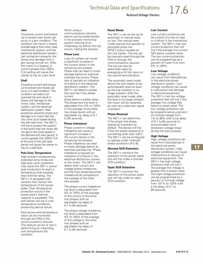
Volume 10—Enclosed Control CA08100012E—November 2012 www.eaton.com V10-T17-71
17
17
17
17
17
17
17
17
17
17
17
17
17
17
17
17
17
17
17
17
17
17
17
17
17
17
17
17
17
17
17.6Technical Data and Specifications
Reduced Voltage Starters
Jam
Excessive current and torque up to locked rotor levels can occur in a jam condition. The condition can result in stress and damage to the motor, load, mechanical system, and the electrical distribution system. Jam protection prevents the stress and damage from a jam during normal run. After the motor is in bypass, a current greater than 300% FLA setting will cause the starter to trip on a jam fault.
Stall
Excessive current and torque up to locked rotor levels can occur in a stall condition. The condition can lead to an overload trip and result in stress and damage to the motor, load, mechanical system, and the electrical distribution system. Stall protection prevents stress and damage to a motor that has not come up to speed during the soft start time. The S811+ will trip to protect the system in the event that the motor did not get to the rated speed in the defined soft start period. A current greater than 200% FLA at the end of the soft start period will cause the starter to trip on a stall fault.
Pole Over Temperature
High ambient temperatures, extended ramp times and high duty cycle conditions may cause the S811+ power pole conductors to reach a temperature that exceeds their thermal rating. The S811+ is equipped with sensors that monitor the temperature of the power poles. Over temperature protection occurs if the power pole’s thermal capacity is exceeded. The soft starter will trip in over temperature conditions, preventing device failure.
Each power pole temperature value can be monitored through the DIM or the communications network. This feature can be of use in determining an impending over temperature trip condition.
When using a communications network, alarms can be implemented in the process monitoring system warning of an impending trip before the trip occurs, halting the process.
Phase Loss
Loss of a phase can cause a significant increase in the current drawn in the remaining two phases. Phase loss can lead to motor damage before an eventual overload trip occurs. Phase loss is typically an indication of a failure in the electrical distribution system. The S811+ will detect a phase loss and trip if any phase current drops below a preset value. The phase loss trip level is adjustable from 0% to 100% of the average of the other two phase levels with an adjustable trip delay of 0.1 to 60 seconds.
Phase Imbalance
Phase current or voltage imbalance can cause a significant increase in the current drawn in the remaining two phases. Phase imbalance can lead to motor damage before an eventual overload trip. Phase imbalance is typically an indication of a failure in the electrical distribution system or the motor. The S811+ will detect both current and voltage phase imbalances and trip if any phase becomes imbalanced as compared to the average of the other two phases.
The phase current imbalance trip level is adjustable from 0% to 100% of the average of the current in the other two phases with an adjustable trip delay of 0.1 to 60 seconds.
The phase voltage imbalance trip level is adjustable from 0% to 100% of the average of the voltage in the other two phases with an adjustable trip delay of 0.1 to 60 seconds.
Reset Mode
The S811+ can be set up for automatic or manual reset on trip. The manual reset mode requires the operator to physically press the RESET button located on the soft starter. The trip can be manually reset through the DIM or through the communications network. The trip can also be electrically reset by energizing a 24 Vdc input on the control terminal block.
The automatic reset mode allows the soft starter to be automatically reset as soon as the trip condition is no longer present. With the automatic reset mode, after the fault is no longer present, the motor will be restarted as soon as a valid start signal is present.
Phase Reversal
The S811+ can determine if the proper line phase sequence is present by default. The device will trip if the line phase sequence is something other than A-B-C. The S811+ can be configured to operate under reversed phase conditions (A-C-B).
Shorted SCR Detection
The S811+ monitors the operation of the power poles and will trip under a shorted SCR condition.
Open SCR Detection
The S811+ monitors the operation of the power poles and will trip under an open SCR condition.
Low Current
Low current conditions can be a result of a loss of load or a failure in the mechanical system. The S811+ has low current protection that will trip if the average rms current falls below a preset value. The low current protection can be programmed as a percent of motor FLA from 0% to 100%.
Low VoltageLow voltage conditions can result from disturbances in the electrical power distribution system. Low voltage conditions can cause a malfunction and damage to electrical equipment. The S811+ has low voltage protection that will trip if the average rms voltage falls below a preset value. The low voltage protection can be programmed as a percent of nominal voltage from 1% to 99% with a trip delay of 0.1 to 60 seconds to accommodate short temporary voltage drops during the start process.
High VoltageHigh voltage conditions can result from disturbances in the electrical power distribution system. High voltage conditions can cause malfunctions or failures of electrical equipment. The S811+ has high voltage protection that will trip if the average rms voltage is greater than a preset value. The high voltage protection can be programmed as a percent of nominal voltage from 101% to 120% with a trip delay of 0.1 to 60 seconds.

V10-T17-72 Volume 10—Enclosed Control CA08100012E—November 2012 www.eaton.com
17
17
17
17
17
17
17
17
17
17
17
17
17
17
17
17
17
17
17
17
17
17
17
17
17
17
17
17
17
17
17.6 Technical Data and Specifications
Reduced Voltage Starters
Monitoring CapabilitiesThe S811+ has an impressive array of system monitoring capabilities that allows users to access real time process and diagnostic data. This data can be viewed at the device with the DIM or through a communications network. Data over a communications network can provide valuable insight into the condition of the equipment and processes. Maintenance and production personnel can monitor critical operational and maintenance data from a central control station that can be located far away from the production facility. Process data can be monitored to determine system anomalies that may indicate a need for preventive maintenance or an impeding failure. Adjustments made through the communications network can reduce costs by minimizing the time traveling to the location where the motor controls are located. When faults do occur, real time fault data can assist maintenance in trouble-shooting and planning repair resources. Remote reset signals can be given to tripped devices without the need for manual intervention by maintenance personnel.
Average Line Current
Provides the average of the three-phase rms line currents in amps, accurate to within 2%. Current data can be used to indicate a need for maintenance. Increased currents in a fixed load application can indicate a reduction in system efficiencies and performance, signifying system maintenance is due.
Average Pole Current
Provides the average of the three-phase rms pole currents in amps, accurate to within 2%. The pole current is the current through the soft starter. The line and pole current will be identical in inline applications, and will differ in inside-the-delta applications.
Average Line Current as a % FLA
Provides the average rms line current as a percentage of the S811+ FLA setting.
Three-Phase Line Currents
Provides three rms phase line currents in amps, accurate to within 2%. Imbalances or changes in the relative phase current to one another can indicate anomalies in the motor or electrical distribution system.
Three-Phase Pole Currents
Provides three rms phase pole currents in amps, accurate to within 2%. The pole current is the current through the soft starter. The line and pole current will be identical in in-line applications, and will differ in inside-the-delta applications.
Three-Phase Line Voltages
Provides the individual rms three-phase line voltages. Imbalances or changes in |the relative phase voltage to one another can indicate anomalies in the motor or electrical distribution system. Voltage can be used to monitor electrical distribution system performance. Warnings, alarms and system actions to low or high voltage conditions can be implemented.
Percent Thermal Memory
Provides the real time calculated thermal memory value. The S811+ calculates thermal memory value. A 100% value represents the maximum safe internal temperature of the motor. When the thermal memory value reaches 100%, an overload trip will occur, removing power to the motor.
The thermal memory value can be of great use in determining an impending overload trip condition. When using a communications network, alarms can be implemented in the process monitoring system warning of an impending trip before the trip occurs, halting the process. Costly system downtime can be avoided.
DC Control Voltage
Monitors level of the 24 Vdc control voltage. Fluctuations in control voltage can cause component malfunction and failure. System control voltage data can be used to implement warnings, alarms and system actions to low or high voltage conditions.
Pole Temperature
Increases in power pole temperature are caused by increases in ambient temperature, start/stop times and start duty cycles. Changes in pole temperatures represent a change in system operating conditions. Identifying unexpected operating conditions or changes can prompt maintenance and aid in process evaluation activities.
PCB Device Temperature
An increase in printed circuit board (PCB) device temperature is a strong indication of an increase in ambient temperature. High ambient temperature operation can be identified with the device temperature data. Device temperature increases can be due to undersized enclosures, failure of cooling fans or blocked venting. High operating temperatures will reduce the life of all electrical equipment in the enclosure.
Start Count
Start count data can be used to monitor system output, schedule preventative maintenance, identify system anomalies and identify changes in system operation.
Average Line Power
Provides the average of the three-phase line power in kilowatts, accurate to 5%. Power data may be used to monitor power transmitted to the load. Increased power demand may indicate degraded system components or connections. Additionally, such data is useful in determine power utilization in branch circuits consisting of multiple loads.
Power Factor
Provides the three-phase power factor value, accurate to 5%. The power factor of the circuit may be used to identify circuit conditions that may need to be corrected due to low power factor indications. Low circuit power factor can indicate improper or degraded components.

Volume 10—Enclosed Control CA08100012E—November 2012 www.eaton.com V10-T17-73
17
17
17
17
17
17
17
17
17
17
17
17
17
17
17
17
17
17
17
17
17
17
17
17
17
17
17
17
17
17
17.7Technical Data and Specifications
NEMA Vacuum Break Contactors and Starters
Specifications
Note1 For transformers having inrush currents of not more than 20 times the rated full load current.
Description
NEMA Special PurposeSize 4 Size 5 Size 6 160A 320A 540A 610AV201K4_ V201K5_ V201K6_ V201KR_ V201KT_ V201KV_ V201KZ_
Poles 3 3 3 3 3 3 3
Maximum voltage rating 600V 600V 600V 1500V 1500V 1500V 1500V
Ampere rating 135A 270A 540A 160A 320A 540A 610A
Frequency, Hz 50/60 50/60 50/60 50/60 50/60 50/60 50/60
Maximum closing current 1600A 3000A 6000A 1600A 3000A 6000A 6000A
Maximum interrupting current 1600A 3000A 6000A 1600A 3000A 6000A 6000A
Short time current
1 second 2400A rms 4500A rms 9000A rms 2400A rms 4500A rms 9000A rms 9000A rms
2 seconds 1600A rms 3000A rms 6000A rms 1600A rms 3000A rms 6000A rms 6000A rms
Dielectric strength 2200 Vac 5375 Vac 5375 Vac 2200 Vac 5375 Vac 5375 Vac 5375 Vac
Maximum allowable interrupting 1200/hr. — — 1200/hr. — — —
Impulse voltage (1 x 40 ms) 15 kV 15 kV 15 kV 15 kV 15 kV 15 kV 15 kV
Maximum motor horsepower at
200V 40 hp 75 hp 150 hp 50 hp 100 hp 150 hp 200 hp
230V 50 hp 100 hp 200 hp 60 hp 125 hp 200 hp 200 hp
380V 75 hp 150 hp 300 hp 100 hp 200 hp 300 hp 300 hp
460V 100 hp 200 hp 400 hp 125 hp 250 hp 400 hp 450 hp
575V 100 hp 200 hp 400 hp 150 hp 300 hp 400 hp 500 hp
800V — — — 200 hp 400 hp — 800 hp
1000V — — — 250 hp — — 1000 hp
1500V — — — 400 hp 800 hp 1300 hp 1600 hp
Three-phase capacitive switching (kVAR)
230V 40 kVAR 80 kVAR 160 kVAR 50 kVAR 80 kVAR 160 kVAR 176 kVAR
460V 80 kVAR 160 kVAR 320 kVAR 100 kVAR 160 kVAR 320 kVAR 356 kVAR
600V 100 kVAR 200 kVAR 400 kVAR 125 kVAR 200 kVAR 400 kVAR 400 kVAR
1500V — — — 205 kVAR 500 kVAR — 1000 kVAR
Transformer switching (kVA) 1
Single-phase, two-pole
120V 6.8 kVA 14 kVA 27 kVA 8 kVA 14 kVA 27 kVA 27 kVA
240V 14 kVA 27 kVA 54 kVA 16 kVA 27 kVA 54 kVA 54 kVA
480V 27 kVA 54 kVA 108 kVA 32 kVA 54 kVA 108 kVA 108 kVA
600V 34 kVA 68 kVA 135 kVA 40 kVA 68 kVA 135 kVA 135 kVA
Three-phase, three-pole
240V 23 kVA 47 kVA 94 kVA 27 kVA 47 kVA 94 kVA 94 kVA
480V 47 kVA 94 kVA 188 kVA 55 kVA 94 kVA 188 kVA 188 kVA
600V 59 kVA 117 kVA 234 kVA 70 kVA 117 kVA 234 kVA 234 kVA

V10-T17-74 Volume 10—Enclosed Control CA08100012E—November 2012 www.eaton.com
17
17
17
17
17
17
17
17
17
17
17
17
17
17
17
17
17
17
17
17
17
17
17
17
17
17
17
17
17
17
17.7 Technical Data and Specifications
NEMA Vacuum Break Contactors and Starters
Electrical Characteristics—Apply to Both NEMA and Special Purpose Types
Electrical Characteristics Coil Data (AC Supply Rectified)
DescriptionSize 4 (160A)
Size 5 (320A)
Size 6 (540A and 610A)
DC coil data—burden(AC supply rectified)
Open VA 300 VA 500 VA 1450 VA
Closed VA 30 VA 25 VA 32 VA
Closed watts 6W 20W 30W
Pickup volts 70% of rated coil volts
Dropout volts 50% of rated coil volts
Pickup time in Hz 1.5–2 Hz
Dropout time in Hz 6–6.15 Hz
Max. voltage rating 600V 600V 600V
Max. closing current 1600A 3000A 6000A
Max. interrupting current 1600A 3000A 6000A
Short time current
1 second 2400A rms 4500A rms 9000A rms
2 seconds 1600A rms 3000A rms 6000A rms
BurdenSize 4 (160A)
Size 5 (320A)
Size 6 (540A and 610A)
Inrush VA 300 600 1700
Sealed VA 30 20 28
Sealed watts 6 20 28
Pickup volts 70% of rated coil volts
Dropout volts 50% of rated coil volts
Pickup time in Hz 1.5–2 1.5–2 1.5–2
Dropout time in Hz 6–7.5 6–6.15 6–6.15

Volume 10—Enclosed Control CA08100012E—November 2012 www.eaton.com V10-T17-75
17
17
17
17
17
17
17
17
17
17
17
17
17
17
17
17
17
17
17
17
17
17
17
17
17
17
17
17
17
17
17.8Technical Data and Specifications
Control Power Transformer Selection
Control Power Transformer Selection ProcedureThe following steps will assure that the secondary voltage delivered by your transformer will be either 85%, 90% or 95% of the nameplate secondary voltage under maximum inrush conditions, at rated input voltage. A typical selection example based on these steps follows.
Step 1Calculate the total SEALED (steady state) VA load of your control circuit. This is done by adding the continuous VA requirements of the maximum number of components that will be energized at any given time, including non-inductive as well as inductive components. For Sealed VA data see Page V10-T17-76.
Step 2Calculate the PEAK INRUSH VA of your control circuit. First, analyze the sequence of operation of all components. Then add together the inrush VA ratings of the components that will be energized simultaneously. Next, determine the peak—or maximum simultaneous—inrush VA load that the transformer will “see.” The VA requirements for indicating lights, timers and other non-inductive components which do not have an inrush VA also should be included since they will present a load to the transformer at the time of maximum inrush.
Step 3Calculate the TRANSFORMER SELECTION INRUSH VA. Use the following formula:
Selection Inrush =
Note: Transformer selection inrush VA also can be determined by adding the inrush VA and sealed VA arithmetically, but this usually results in an oversized transformer.
Step 4Determine the correct transformer NAMEPLATE VA RATING. Refer to the Inrush/Regulation Data table: If the line supply to the transformer is fairly stable (does not vary more than 5%), use the 90% secondary voltage column—the 90% column is most commonly used. If the line supply voltage varies up to 10%, use the 95% voltage regulation column. To determine the correct VA transformer rating, go down the column until you arrive at the inrush VA rating closest to, but not less than, the Transformer Selection Inrush VA calculated in Step 3. The left hand column of the table will give the corresponding transformer NAMEPLATE VA RATING.
(VA Sealed)2 + (VA Inrush)2
Inrush/Regulation Data
Note: When evaluating supply-line stability, remember that supply-line voltage drop frequently is associated with motor-starting inrush current. When motors and motor controls are connected to a common
feeder, the controls will experience a momentary voltage dip when the motor starts. This reduces the control transformer voltage supplied to the motor starting contactor and may cause the contactor to chatter or drop out.
Selection ExampleSteps 1 and 2By following Steps 1 and 2 described in column one at left, analysis of the control
circuits shows the following sealed VA and inrush VA data:
Example Data
Step 3Following Step 3 in column two at left, the Transformer Selection Inrush VA is calculated at 1773 VA.
Transformer Selection VA
Steps 4 and 5Following Steps 3 and 4 at left, the Inrush/Regulation Data Chart is then consulted to find the correction nameplate VA size of the transformer. Under the 90% Secondary Voltage column, we find that a 320 VA transformer will deliver 2224 VA, amply covering circuit demands of 1800 Inrush VA. Checking this selection against the requirements of 311 VA sealed, we confirm that a 320 VA transformer will be sufficient.
TransformerVA Rating55°C
Inrush VA—40% Power FactorAt 95%SecondaryVoltage
At 90%SecondaryVoltage
At 85%SecondaryVoltage
60 137 185 227
95 242 329 409
105 294 407 512
180 592 842 1071
225 929 1312 1663
275 1271 1801 2288
320 1581 2224 2816
380 2124 3048 3895
550 3196 4604 5896
850 5500 7914 10,141
1100 8382 12,067 15,477
1500 11,100 16,066 21,032
2000 21,820 24,356 41,100
3000 29,123 32,770 59,997
5000 74,595 111,000 145,000
7500 104,000 162,000 219,000
10,000 111,000 166,000 237,000
Qty. Description Sealed VA Inrush VA
3 Three-pole Size 1 contactors 60 309
2 Three-pole Size 3 contactors 99 780
4 Relays 88 620
2 Electronic timers 36 36
4 Indicating lights 28 28
Totals 311 1773
3,240,250=
1800=
(VA Sealed)2 + (VA Inrush)2=
(311)2 + (1773)2=
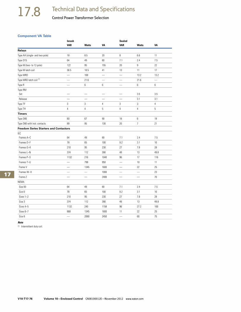
V10-T17-76 Volume 10—Enclosed Control CA08100012E—November 2012 www.eaton.com
17
17
17
17
17
17
17
17
17
17
17
17
17
17
17
17
17
17
17
17
17
17
17
17
17
17
17
17
17
17
17.8 Technical Data and Specifications
Control Power Transformer Selection
Component VA Table
Note1 Intermittent duty coil.
Inrush SealedVAR Watts VA VAR Watts VA
Relays
Type AA (single- and two-pole) 18 8.5 20 8 6.6 11
Type D15 64 49 80 7.1 2.4 7.5
Type M (two- to 12-pole) 122 95 155 20 9 22
Type M latch coil 36.5 18.5 41 13 11 17
Type MRD — 168 — — 13.2 13.2
Type MRD latch coil 1 — 21.6 — — 21.6 —
Type R — 6 6 — 6 6
Type RM
Set — — — — 3.5 3.5
Release — — — — 3.1 3.1
Type TF 3 3 4 3 3 4
Type TH 4 4 5 4 4 5
Timers
Type D80 60 67 90 18 6 19
Type D80 with inst. contacts 89 95 130 20 7 21
Freedom Series Starters and Contactors
IEC
Frames A–C 64 49 80 7.1 2.4 7.5
Frames D–F 78 65 100 9.2 3.1 10
Frames G–K 210 95 230 27 7.8 28
Frames L–N 374 112 390 48 13 49.8
Frames P–S 1132 216 1040 96 17 116
Frames T–U — 798 950 — 10 11
Frame V — 1345 1600 — 22 25
Frames W–X — — 1000 — — 23
Frame Z — — 2400 — — 70
NEMA
Size 00 64 49 80 7.1 2.4 7.5
Size 0 78 65 100 9.2 3.1 10
Sizes 1–2 210 95 230 27 7.8 28
Size 3 374 112 390 48 13 49.8
Sizes 4–5 1132 240 1158 96 27.2 100
Sizes 6–7 868 1345 1600 11 22 25
Size 8 — 2060 2450 — 60 75

Volume 10—Enclosed Control CA08100012E—November 2012 www.eaton.com V10-T17-77
17
17
17
17
17
17
17
17
17
17
17
17
17
17
17
17
17
17
17
17
17
17
17
17
17
17
17
17
17
17
17.9Technical Data and Specifications
Ampere Ratings of AC Motors
Ampere ratings of motors vary somewhat, depending upon the type of motor. The values given below are for drip-proof, Class B insulated (T Frame) where available, 1.15 service factor, NEMA Design B motors. These values represent an average
full load motor current that was calculated from the motor performance data published by several motor manufacturers. In the case of high torque squirrel cage motors, the ampere ratings will be at least 10% greater than the values given below.
Caution—These average ratings could be high or low for a specific motor and therefore heater coil selection on this basis always involves risk. For fully
reliable motor protection, select heater coils on the basis of full load current rating as shown on the motor nameplate.
Ampere Ratings of Three-Phase, 60 Hz, AC Induction Motor
Notes1 To convert horsepower to kW, multiply horsepower by 0.7457.2 380V 50 Hz.
hp 1
Syn.SpeedRPM
Current in Amperes
hp 1
Syn.SpeedRPM
Current in Amperes
200V 230V 380V 2 460V 575V 2200V 200V 230V 380V 2 460V 575V 2200V
1/4 1800 1.09 0.95 0.55 0.48 0.38 — 25 3600 69.9 60.8 36.8 30.4 24.3 —1200 1.61 1.40 0.81 0.70 0.56 — 1800 74.5 64.8 39.2 32.4 25.9 —900 1.84 1.60 0.93 0.80 0.64 — 1200 75.4 65.6 39.6 32.8 26.2 —
1/3 1800 1.37 1.19 0.69 0.60 0.48 — 900 77.4 67.3 40.7 33.7 27.0 —1200 1.83 1.59 0.92 0.80 0.64 — 30 3600 84.8 73.7 44.4 36.8 29.4 —900 2.07 1.80 1.04 0.90 0.72 — 1800 86.9 75.6 45.7 37.8 30.2 —
1/2 1800 1.98 1.72 0.99 0.86 0.69 — 1200 90.6 78.8 47.6 39.4 31.5 —1200 2.47 2.15 1.24 1.08 0.86 — 900 94.1 81.8 49.5 40.9 32.7 —900 2.74 2.38 1.38 1.19 0.95 — 40 3600 111 96.4 58.2 48.2 38.5 —
3/4 1800 2.83 2.46 1.42 1.23 0.98 — 1800 116 101 61.0 50.4 40.3 —1200 3.36 2.92 1.69 1.46 1.17 — 1200 117 102 61.2 50.6 40.4 —900 3.75 3.26 1.88 1.63 1.30 — 900 121 105 63.2 52.2 41.7 —
1 3600 3.22 2.80 1.70 1.40 1.12 — 50 3600 138 120 72.9 60.1 48.2 —1800 4.09 3.56 2.06 1.78 1.42 — 1800 143 124 75.2 62.2 49.7 —1200 4.32 3.76 2.28 1.88 1.50 — 1200 145 126 76.2 63.0 50.4 —900 4.95 4.30 2.60 2.15 1.72 — 900 150 130 78.5 65.0 52.0 —
1-1/2 3600 5.01 4.36 2.64 2.18 1.74 — 60 3600 164 143 86.8 71.7 57.3 —1800 5.59 4.86 2.94 2.43 1.94 — 1800 171 140 90.0 74.5 59.4 —1200 6.07 5.28 3.20 2.64 2.11 — 1200 173 150 91.0 75.0 60.0 —900 6.44 5.60 3.39 2.80 2.24 — 900 177 154 93.1 77.0 61.5 —
2 3600 6.44 5.60 3.39 2.80 2.24 — 75 3600 206 179 108 89.6 71.7 —1800 7.36 6.40 3.87 3.20 2.56 — 1800 210 183 111 91.6 73.2 —1200 7.87 6.84 4.14 3.42 2.74 — 1200 212 184 112 92.0 73.5 —900 9.09 7.90 4.77 3.95 3.16 — 900 222 193 117 96.5 77.5 —
3 3600 9.59 8.34 5.02 4.17 3.34 — 100 3600 — 231 140 115 92.2 —1800 10.8 9.40 5.70 4.70 3.76 — 1800 — 236 144 118 94.8 23.61200 11.7 10.2 6.20 5.12 4.10 — 1200 — 239 145 120 95.6 24.2900 13.1 11.4 6.90 5.70 4.55 — 900 — 252 153 126 101 24.8
5 3600 15.5 13.5 8.20 6.76 5.41 — 125 3600 — 292 176 146 116 —1800 16.6 14.4 8.74 7.21 5.78 — 1800 — 293 177 147 117 29.21200 18.2 15.8 9.59 7.91 6.32 — 1200 — 298 180 149 119 29.9900 18.3 15.9 9.60 7.92 6.33 — 900 — 305 186 153 122 30.9
7-1/2 3600 22.4 19.5 11.8 9.79 7.81 — 150 3600 — 343 208 171 137 —1800 24.7 21.5 13.0 10.7 8.55 — 1800 — 348 210 174 139 34.81200 25.1 21.8 13.2 10.9 8.70 — 1200 — 350 210 174 139 35.5900 26.5 23.0 13.9 11.5 9.19 — 900 — 365 211 183 146 37.0
10 3600 29.2 25.4 15.4 12.7 10.1 — 200 3600 — 452 257 226 181 —1800 30.8 26.8 16.3 13.4 10.7 — 1800 — 458 265 229 184 46.71200 32.2 28.0 16.9 14.0 11.2 — 1200 — 460 266 230 184 47.0900 35.1 30.5 18.5 15.2 12.2 — 900 — 482 279 241 193 49.4
15 3600 41.9 36.4 22.0 18.2 14.5 — 250 3600 — 559 338 279 223 —1800 45.1 39.2 23.7 19.6 15.7 — 1800 — 568 343 284 227 57.51200 47.6 41.4 25.0 20.7 16.5 — 1200 — 573 345 287 229 58.5900 51.2 44.5 26.9 22.2 17.8 — 900 — 600 347 300 240 60.5
20 3600 58.0 50.4 30.5 25.2 20.1 — 300 1800 — 678 392 339 271 69.01800 58.9 51.2 31.0 25.6 20.5 — 1200 — 684 395 342 274 70.01200 60.7 52.8 31.9 26.4 21.1 — 400 1800 — 896 518 448 358 91.8900 63.1 54.9 33.2 27.4 21.9 — 500 1800 — 1110 642 555 444 116

V10-T17-78 Volume 10—Enclosed Control CA08100012E—November 2012 www.eaton.com
17
17
17
17
17
17
17
17
17
17
17
17
17
17
17
17
17
17
17
17
17
17
17
17
17
17
17
17
17
17
17.10 Technical Data and Specifications
Product Codes
Product Codes—By Description
Product Codes—By Code
Description Code Description Code
Accessories, Fuse Clips and Cover Control AF40 Multispeed, NEMA Freedom AI61
C361 Flange Mounted Switch AN20 Multispeed, Vacuum AI64
C371 Circuit Breaker Operator AN50 Non-Combination Enclosed Starters, Specials AM50
Combination Enclosed Starters, Specials AM60 Non-Combination Full Voltage NEMA Freedom Contactor AB61
Combination Full Voltage NEMA Freedom Starter AE61 Non-Combination Full Voltage NEMA Freedom Starter AA61
Combination Full Voltage Type 4X and 7/9 NEMA Starter AE65 Non-Combination Full Voltage Type 4X Starter AA65
Combination Full Voltage Vacuum Starter AE64 Non-Combination Full Voltage Type 7/9 Explosion Proof Starter AA66
Combination NEMA HVAC EH61 Non-Combination Full Voltage Type 7/9 NEMA Starter AE66
Combination Reduced Voltage IT. Soft Starters NS22 Non-Combination Full Voltage Vacuum Contactor AB64
Duplex Pump Panels, Freedom AJ65 Non-Combination Full Voltage Vacuum Starter AA64
Ghisalba Coils and Feeder Groups HD70A1 Non-Combination Reduced Voltage IT. Soft Starter NS12
Lighting, Electrically Held Enclosed A202 Contactor AB76 Oil Pump Panel, NEMA Freedom AJ71
Lighting, Electrically Held Enclosed CN35 Contactor AB66 Pump Panel, NEMA Freedom AJ61
Lighting, Magnetically Latched Enclosed A202 Contactor AB72 Pump Panel, Vacuum AJ64
Lighting, Mechanically Held Enclosed A202 Contactor AB67 Reduced Voltage IEC Starter AG62
Lighting, Mechanically Held Enclosed C30 Contactor AB79 Reduced Voltage NEMA Starter AG61
Manual Starters Type B100 2916 Reduced Voltage Vacuum Starter AG64
Manual Starters Type MS 2915 Reduced Voltage, IT. AG68
Multispeed Combination, NEMA Freedom AI65 Renewal Parts for Enclosed Control, C361, C371, C400 HD70H4
Code Description Code Description
2915 Manual Starters Type MS AG62 Reduced Voltage IEC Starter
2916 Manual Starters Type B100 AG64 Reduced Voltage Vacuum Starter
AA61 Non-Combination Full Voltage NEMA Freedom Starter AG68 Reduced Voltage, IT.
AA64 Non-Combination Full Voltage Vacuum Starter AI61 Multispeed, NEMA Freedom
AA65 Non-Combination Full Voltage Type 4X Starter AI64 Multispeed, Vacuum
AA66 Non-Combination Full Voltage Type 7/9 Explosion Proof Starter AI65 Multispeed Combination, NEMA Freedom
AB61 Non-Combination Full Voltage NEMA Freedom Contactor AJ61 Pump Panel, NEMA Freedom
AB64 Non-Combination Full Voltage Vacuum Contactor AJ64 Pump Panel, Vacuum
AB66 Lighting, Electrically Held Enclosed CN35 Contactor AJ65 Duplex Pump Panels, Freedom
AB67 Lighting, Mechanically Held Enclosed A202 Contactor AJ71 Oil Pump Panel, NEMA Freedom
AB72 Lighting, Magnetically Latched Enclosed A202 Contactor AM50 Non-Combination Enclosed Starters, Specials
AB76 Lighting, Electrically Held Enclosed A202 Contactor AM60 Combination Enclosed Starters, Specials
AB79 Lighting, Mechanically Held Enclosed C30 Contactor AN20 C361 Flange Mounted Switch
AE61 Combination Full Voltage NEMA Freedom Starter AN50 C371 Circuit Breaker Operator
AE64 Combination Full Voltage Vacuum Starter EH61 Combination NEMA HVAC
AE65 Combination Full Voltage Type 4X and 7/9 NEMA Starter HD70A1 Ghisalba Coils and Feeder Groups
AE66 Non-Combination Full Voltage Type 7/9 NEMA Starter HD70H4 Renewal Parts for Enclosed Control, C361, C371, C400
AF40 Accessories, Fuse Clips and Cover Control NS12 Non-Combination Reduced Voltage IT. Soft Starter
AG61 Reduced Voltage NEMA Starter NS22 Combination Reduced Voltage IT. Soft Starters