Technical Configuration Guide for Microsoft Network … · > Technical Configuration Guide for...
95
> Technical Configuration Guide for Microsoft Network Load Balancing Enterprise Solutions Engineering Document Date: March 9, 2006 Document Version: 1.0 Ethernet Switch and Ethernet Routing Switch Engineering
Transcript of Technical Configuration Guide for Microsoft Network … · > Technical Configuration Guide for...

> Technical Configuration Guide for Microsoft Network Load Balancing Enterprise Solutions Engineering Document Date: March 9, 2006 Document Version: 1.0
Ethernet Switch and Ethernet Routing Switch Engineering

Technical Configuration Guide for: Microsoft Network Load Balancing v1.0 March, 2006
______________________________________________________________________________________________________
NORTEL External Distribution 1
Copyright © 2006 Nortel. All rights reserved. NORTEL CONFIDENTIAL: The information contained in this document is the property of Nortel. Except as specifically authorized in writing by Nortel, the holder of this document shall not copy or otherwise reproduce, or modify, in whole or in part, this document or the information contained herein. The holder of this document shall keep the information contained herein confidential and protect same from disclosure and dissemination to third parties and use same solely for the training of authorized individuals. This information is subject to change without notice. Nortel, the Nortel logo, Shasta, and Passport are trademarks of Nortel.
SUN, SUNLINK, and SOLARIS are trademarks of Sun Microsystems Inc. SPARC is a trademark of SPARC International Inc. UNIX is a trademark licensed exclusively through X/Open Company Ltd. OPENVIEW is a trademark of Hewlett-Packard Company. ORACLE is a trademark of Oracle Corporation.
Disclaimer This engineering document contains the best information available at the time of publication in terms of supporting the application and engineering of Nortel products in the customer environment. They are solely for the use by Nortel customers and meant as a guide for network engineers and planners from a network engineering perspective. All information is subject to interpretation based on internal Nortel test methodologies which were used to derive the various capacity and equipment performance criteria and should be reviewed with Nortel engineering primes prior to implementation in a live environment.

Technical Configuration Guide for: Microsoft Network Load Balancing v1.0 March, 2006
______________________________________________________________________________________________________
NORTEL External Distribution 2
Abstract The document provides an overview on how to configure Nortel Ethernet & Ethernet Routing Switches to support Microsoft’s Network Load Balancing (NLB) server clustering technology.
Technical Configuration Guide for: Microsoft Network Load Balancing v1.0 March, 2006
______________________________________________________________________________________________________
NORTEL External Distribution 3
Table of Contents 1. OVERVIEW: NETWORK LOAD BALANCING ........................................................................... 4
1.1 UNICAST MODE OF OPERATION ..................................................................................................... 6 1.2 MULTICAST MODE OF OPERATION ................................................................................................ 8 1.3 MAC ADDRESS FORMATS ........................................................................................................... 10 1.4 IMPLEMENTATION MODELS ......................................................................................................... 12
2. NETWORK LOAD BALANCING SWITCH SUPPORT ............................................................. 16 2.1 NORTEL SWITCH SUPPORT MATRIX............................................................................................. 16 2.2 MULTICAST FLOOD SUPPRESSION................................................................................................ 17 2.3 DEPLOYING MICROSOFT NETWORK LOAD BALANCING............................................................... 18
3. CONFIGURATION .......................................................................................................................... 24 3.1 WINDOWS 2003 SERVERS ............................................................................................................ 24 3.2 ETHERNET SWITCH SOFTWARE DEPENDENCIES........................................................................... 24 3.3 CREATING A WINDOWS SERVER UNICAST CLUSTER.................................................................... 25 3.4 CREATING A WINDOWS SERVER MULTICAST CLUSTER ............................................................... 38 3.5 ETHERNET SWITCH CONFIGURATION EXAMPLE .......................................................................... 51 3.6 ERS 1600 CONFIGURATION EXAMPLE......................................................................................... 53 3.7 ERS 5500 CONFIGURATION EXAMPLE......................................................................................... 64 3.8 ERS 8300 CONFIGURATION EXAMPLE......................................................................................... 76 3.9 ERS 8600 CONFIGURATION EXAMPLE 1...................................................................................... 82 3.10 ERS 8600 CONFIGURATION EXAMPLE 2...................................................................................... 88
4. APPENDIX......................................................................................................................................... 93 A. NLB PORT RULES OPTIONS ............................................................................................................. 93 B. RESOURCES & REFERENCE DOCUMENTS ......................................................................................... 94

Technical Configuration Guide for: Microsoft Network Load Balancing v1.0 March, 2006
______________________________________________________________________________________________________
NORTEL External Distribution 4
1. Overview: Network Load Balancing Network Load Balancing is a clustering technology offered by Microsoft as part of all Windows 2000 / Windows 2003 Server family of operating systems. Network Load Balancing uses a distributed algorithm to load balance network traffic across a number of hosts, enhancing the scalability and availability of mission critical, IP based services, such as Web, VPN, Streaming Media, Firewalls, etc. Network Load Balancing also provides high availability by detecting host failures and automatically redistributing traffic to remaining operational hosts.
Figure 1.1 – Network Load Balancing Cluster
With Network Load Balancing, each host runs separate copies of the desired server applications, such as Web Server, FTP Server, or ISA Firewall. Network Load Balancing distributes incoming client requests to the hosts in the cluster group. The load weight to be handled by each host can be configured by the administrator and hosts can be dynamically added or removed from the cluster as necessary. In addition, Network Load Balancing can direct all traffic to a designated single host, called the default host. Microsoft Network Load Balancing provides the following benefits:
• High availability for applications by redirecting incoming network traffic to working cluster hosts. If a cluster host fails or is offline, existing connections to an offline host are lost, but the Application remains available. In most cases (for example, with Web servers), client software automatically retries the failed connections, and the client may experience few second delay in receiving a response.
• Scalability by clustering of two or more host computers together. Clients access the
cluster using either a single IP address for multiple applications or individual addresses for each application. The clients are unable to distinguish the cluster from a single server and applications do not identify that they are running in a cluster.
• Higher performance by distributing the incoming network traffic among one or more hosts
assigned to the Network Load Balancing cluster. The hosts in the cluster then

Technical Configuration Guide for: Microsoft Network Load Balancing v1.0 March, 2006
______________________________________________________________________________________________________
NORTEL External Distribution 5
concurrently respond to different client requests, even multiple requests from the same client. For example, a Web browser might obtain each of the multiple images in a single Web page from different hosts within a Network Load Balancing cluster. This speeds up processing and shortens the response time to clients.
Figure 1.2 – Example Cluster

Technical Configuration Guide for: Microsoft Network Load Balancing v1.0 March, 2006
______________________________________________________________________________________________________
NORTEL External Distribution 6
1.1 Unicast Mode of Operation Microsoft’s Network Load Balancing default setting is unicast mode. In unicast mode, Network Load Balancing replaces the network adapters MAC address with a cluster MAC address. All Network Load Balancing host adapters in a cluster share a common cluster MAC address and all frames forwarded to the cluster MAC address are received by all hosts in the cluster.
Figure 1.1.1 – Unicast Mode MAC Address Assignment Sharing a common MAC address amongst multiple hosts’ works fine in shared media such as repeaters (hubs) but can cause issues in switched environments. An Ethernet switch forwards frames to hosts based on MAC addresses. An Ethernet switch does this by learning the MAC address of the host connected to each of its ports. The switch builds a forwarding database which provides a logical mapping of a MAC address to the port which it was learned on. A switch expects that a MAC address is unique, only connected to one port, and therefore will not associate a MAC address with multiple ports of the switch. As described above, Microsoft Network Load Balancing creates a cluster MAC address that is common to all hosts in a cluster. An Ethernet switch would learn this MAC address on multiple ports. Since the switch only associates a MAC address to a single port and not many ports, Network Load Balancing will not function correctly. Microsoft Network Load Balancing solves this problem by masking the cluster MAC address. When enabled, Network Load Balancing creates a bogus MAC address on each host adapter which starts with 02 and contains the host ID in the second octet. The bogus MAC address will appear in the Ethernet frame header and will be learned by the Ethernet switch rather than the cluster MAC address. This ensures that the Ethernet switch will not learn the cluster MAC addresses on multiple ports and will learn unique MAC addresses for each host in the cluster.
Figure 1.1.2 – Unicast Mode MAC Address Masking

Technical Configuration Guide for: Microsoft Network Load Balancing v1.0 March, 2006
______________________________________________________________________________________________________
NORTEL External Distribution 7
If each network adapters MAC address is unique, how are frames delivered to all members of the cluster? Microsoft Network Load Balancing solves this problem with IP. A client will learn the cluster MAC address associated with the virtual IP address using Address Resolution Protocol (ARP). When a client sends an ARP request for the MAC address of the clusters virtual IP address, the ARP response will contain cluster MAC virtual address and not the bogus MAC addresses. Frames from the client will then be forwarded to the clusters virtual IP address with a destination MAC address set to the cluster MAC address. On receipt of the frames, the Ethernet switch will perform a lookup and will not have a forwarding entry for the cluster MAC address. The switch will then flood the frames to all active ports in the broadcast domain so that all hosts in the cluster will receive the frames.
Figure 1.1.3 – Traffic from Clients to a Cluster
Flooding typically isn’t a problem for incoming traffic because the majority of traffic is outbound, not inbound. However if there is a significant amount of inbound traffic and other servers are connected to the same switch, switch flooding can present a problem if the traffic is high enough.

Technical Configuration Guide for: Microsoft Network Load Balancing v1.0 March, 2006
______________________________________________________________________________________________________
NORTEL External Distribution 8
1.2 Multicast Mode of Operation Multicast mode is the second option available for Network Load Balancing. In multicast mode, a multicast MAC address is assigned to all hosts in the cluster but the network adapter's built-in address is retained so that both addresses are used. The multicast MAC address is used for client-to-cluster traffic and the adapter MAC address is used for network traffic specific to the host computer. Microsoft Network Load Balancing multicast mode can be implemented with or without flood suppression. The default mode of operation does not support multicast flood suppression and uses a virtual cluster MAC address that starts with 03-bf. The second mode of operation supports multicast flood suppression by implementing IGMP and the clusters virtual MAC address starts with 01-00.
Figure 1.2.1 – Multicast Mode MAC Address Assignment
Using multicast MAC addresses allows multiple computers to listen on the same MAC address. All the machines listening on the same multicast MAC address are referred to as a "multicast group". Frames sent to the multicast MAC address are accepted by all the network adapters listening to the multicast address and frames directed to a unicast MAC address are accepted by the single host that owns the particular unicast address. As previously mentioned, Network Load Balancing requires that all members of the cluster receive the frames from the clients. By default Layer 2 switches will flood multicast frames to all active switch ports in the broadcast domain which ensures that all hosts in the cluster will receive the frames. Frames from clients are forwarded to the clusters virtual IP address with a destination MAC address set to the cluster multicast MAC address. A client will learn the multicast MAC address of the clusters virtual IP address using Address Resolution Protocol (ARP). When a client sends an ARP request for the MAC address of the clusters virtual IP address, the ARP response will contain the clusters multicast MAC address. Frames from the client will then be forwarded to the clusters virtual IP address with a destination MAC address set to the cluster multicast MAC address. On receipt of the frames, the Ethernet switch will flood the frames to all active ports in the broadcast domain so that all hosts in the cluster will receive the frames.

Technical Configuration Guide for: Microsoft Network Load Balancing v1.0 March, 2006
______________________________________________________________________________________________________
NORTEL External Distribution 9
Figure 1.2.2 – Traffic from Clients to a Cluster
In multicast mode there can be problems with certain Routers and Routing Switches:
1. Some Routers or Routing Switches may not support the ability to map a unicast IP address with a multicast MAC address.
2. Some Routers or Routing Switches may not be able to dynamically learn the clusters virtual MAC address.
3. Some Ethernet Routing Switches only support the ability to associate an ARP entry to a single port. If Network Load Balancing hosts are directly connected to the Ethernet Routing Switch, the frames will not be flooded to all hosts in the cluster. This can be easily solved by moving the Network Load Balancing cluster hosts to a subtended Layer 2 Ethernet Switch so that the static ARP entry is associated to a single port.
One advantage to implementing the multicast version of Network Load Balancing is the ability to leverage IGMP snooping and pruning which provides the ability to suppress multicast flooding on Ethernet switches and only flood frames to specific hosts that request membership to the multicast group.

Technical Configuration Guide for: Microsoft Network Load Balancing v1.0 March, 2006
______________________________________________________________________________________________________
NORTEL External Distribution 10
1.3 MAC Address Formats Microsoft Network Load Balancing can implement either Unicast or Multicast MAC addresses depending on how Network Load Balancing is deployed. The following section describes the IEEE formatting of MAC addresses used with Ethernet as well as the MAC address formats used with Microsoft Network Load Balancing for unicast and multicast modes. In Ethernet there are four types of MAC addresses defined by IEEE: MAC Address Type MAC Address Range Globally Unique x0-xx-xx-xx-xx-xx
x4-xx-xx-xx-xx-xx x8-xx-xx-xx-xx-xx xC-xx-xx-xx-xx-xx
Locally Administered x2-xx-xx-xx-xx-xx x6-xx-xx-xx-xx-xx xA-xx-xx-xx-xx-xx xE-xx-xx-xx-xx-xx
Multicast x1-xx-xx-xx-xx-xx x3-xx-xx-xx-xx-xx x5-xx-xx-xx-xx-xx x7-xx-xx-xx-xx-xx x9-xx-xx-xx-xx-xx xB-xx-xx-xx-xx-xx xD-xx-xx-xx-xx-xx xF-xx-xx-xx-xx-xx (exception broadcast address)
Broadcast FF-FF-FF-FF-FF-FF
1.3.1 Globally Unique Globally unique addresses are allocated by the IEEE in blocks containing 2^24 (16,777,216) addresses and start with even numbers. In each allocation, the first 3 octets are fixed (e.g. 00-12-83 is Nortel) and the last three octets are variable (e.g. 00-00-00 through FF-FF-FF). The fixed portion of the allocation is known formally as the Organizationally Unique Identifier (OUI) and is used informally as the Vendor ID.
1.3.2 Locally Administered
Locally administered addresses are MAC addresses which have the second least significant bit of the first octet is set to '1' (for example, 'xxxxxx1x'). Locally administered addresses enable administrators to assign MAC addresses using their own scheme.
1.3.3 Multicast Multicast addresses have the least significant bit of the first octet set to '1' and start with an odd number. Ethernet multicast addressing is used by protocols which require efficient communication among groups of hosts.

Technical Configuration Guide for: Microsoft Network Load Balancing v1.0 March, 2006
______________________________________________________________________________________________________
NORTEL External Distribution 11
1.3.4 Broadcast Broadcast address is a special case where all bits of the MAC address are set to '1' (e.g. FF-FF-FF-FF-FF-FF). When an adapter receives a packet with a destination broadcast address, it always passes it to the operating system for further processing.
1.3.5 Network Load Balancing Unicast Mode When Microsoft Network Load Balancing is deployed in unicast mode, the globally unique MAC address on the hosts network adapter is replaced with a locally administered MAC address assigned by Microsoft. The locally administered MAC address starts with a 02:xx prefix and the second octet will contain the host id of the host in the cluster.
The clusters virtual MAC address is also a locally administered MAC address and starts with a 02:bf prefix.
Figure 1.3.5 – Host Unicast MAC Assignment
1.3.6 Network Load Balancing Multicast Mode When Microsoft Network Load Balancing is deployed in multicast mode, the globally unique MAC address on the hosts network adapter is retained.
The clusters virtual MAC address is Multicast MAC address assigned by Microsoft and will start with a 03:bf prefix. All the hosts in cluster will be configured with the same multicast cluster MAC address.
Figure 1.3.6 – Host Multicast MAC Assignment

Technical Configuration Guide for: Microsoft Network Load Balancing v1.0 March, 2006
______________________________________________________________________________________________________
NORTEL External Distribution 12
1.4 Implementation Models Microsoft’s Network Load Balancing can be deployed using one of four models. This section provides a brief overview of the supported models and provides advantages and disadvantages of each.
1.4.1 Single Network Adapter in Unicast Mode The single network adapter unicast model is suitable for a cluster in which ordinary network communication among cluster hosts is not required and there is limited dedicated traffic from outside the cluster subnet to specific cluster hosts.
Figure 1.4.1 – Single Adapter Unicast Mode
Advantages
• One network adapter per host is required.
• Minimum configuration is required as unicast mode is the default.
• Works with all routers and L2 switches.
Disadvantages
• Network communication between cluster hosts is not possible.
• All traffic from clients to cluster hosts will be flooded.
• Not supported by all L3 switches.

Technical Configuration Guide for: Microsoft Network Load Balancing v1.0 March, 2006
______________________________________________________________________________________________________
NORTEL External Distribution 13
1.4.2 Single Network Adapter in Multicast Mode The single network adapter multicast model is suitable for a cluster in which ordinary network communication among cluster hosts is necessary or desirable, but in which there is limited dedicated traffic from outside the cluster subnet to specific cluster hosts.
Figure 1.4.2 – Single Adapter Multicast Mode
Advantages
• One network adapter per host is required.
• Network communication between cluster hosts is permitted.
• Supports Internet Group Management Protocol (IGMP) on the cluster hosts to control flooding on the switch.
Disadvantages
• Some Routers or Routing Switches may not support the ability to map a unicast IP address with a multicast MAC address.
• Some Routers or Routing Switches may not be able to dynamically learn the clusters virtual MAC address.
• By default Windows 2003 Server implements IGMPv3 which is not supported by some L2 switches. A registry modification is required to change the default IGMPv3 setting to IGMPv1 or IGMPv2 (See Appendix B).

Technical Configuration Guide for: Microsoft Network Load Balancing v1.0 March, 2006
______________________________________________________________________________________________________
NORTEL External Distribution 14
1.4.3 Multiple Network Adapters in Unicast Mode The multiple network adapter unicast model is suitable for a cluster in which ordinary network communication among cluster hosts is necessary or desirable. It is also appropriate when you want to separate the traffic used to manage the cluster from the traffic occurring between the cluster and client computers.
Figure 1.4.3 – Multiple Adapters Unicast Mode
Advantages
• Network communication between cluster hosts is permitted.
• This model works with all routers and L2 switches.
Disadvantages
• This model requires a second network adapter.
• All traffic from clients to cluster hosts will be flooded.
• Not supported by all L3 switches.
Technical Configuration Guide for: Microsoft Network Load Balancing v1.0 March, 2006
______________________________________________________________________________________________________
NORTEL External Distribution 15
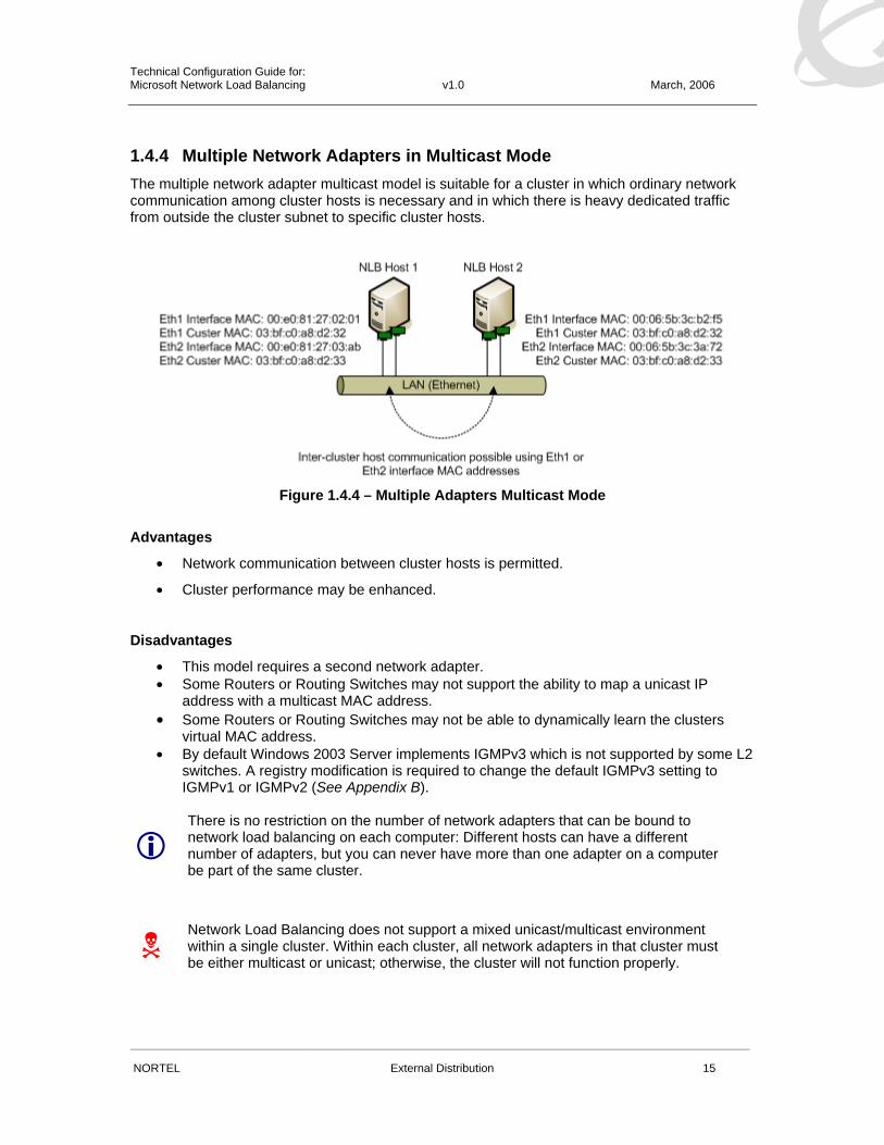
1.4.4 Multiple Network Adapters in Multicast Mode The multiple network adapter multicast model is suitable for a cluster in which ordinary network communication among cluster hosts is necessary and in which there is heavy dedicated traffic from outside the cluster subnet to specific cluster hosts.
Figure 1.4.4 – Multiple Adapters Multicast Mode
Advantages
• Network communication between cluster hosts is permitted.
• Cluster performance may be enhanced.
Disadvantages
• This model requires a second network adapter. • Some Routers or Routing Switches may not support the ability to map a unicast IP
address with a multicast MAC address. • Some Routers or Routing Switches may not be able to dynamically learn the clusters
virtual MAC address. • By default Windows 2003 Server implements IGMPv3 which is not supported by some L2
switches. A registry modification is required to change the default IGMPv3 setting to IGMPv1 or IGMPv2 (See Appendix B).
There is no restriction on the number of network adapters that can be bound to network load balancing on each computer: Different hosts can have a different number of adapters, but you can never have more than one adapter on a computer be part of the same cluster.
Network Load Balancing does not support a mixed unicast/multicast environment within a single cluster. Within each cluster, all network adapters in that cluster must be either multicast or unicast; otherwise, the cluster will not function properly.

Technical Configuration Guide for: Microsoft Network Load Balancing v1.0 March, 2006
______________________________________________________________________________________________________
NORTEL External Distribution 16
2. Network Load Balancing Switch Support Microsoft Network Load Balancing is supported in some fashion by all Nortel Ethernet Switches. However due to the nature of how the Microsoft Network Load Balancing feature works, Network Load Balancing support is dependent on where the clustered servers are placed in the network as well as how the Ethernet Switch the clustered servers are connected to is configured.
2.1 Nortel Switch Support Matrix
Ethernet Switch Model Unicast Support
(L2 Switching)
Unicast Support
(L3 Routing)
Multicast Support
(L2 Switching)
Multicast Support
(L3 Routing) Ethernet Switch 325 Yes N/A Yes (Note 1) N/A Ethernet Switch 425 Yes N/A Yes (Note 1) N/A Ethernet Switch 470 Yes N/A Yes (Note 1) N/A Ethernet Switch 460-24T-PWR Yes N/A Yes (Note 1) N/A Ethernet Routing Switch 1600 Yes No (Note 2) Yes (Note 1) No (Note 3) Ethernet Routing Switch 5500 Yes No (Note 2) Yes (Note 1) No (Note 3) Ethernet Routing Switch 8300 Yes No (Note 2) Yes (Note 1) No Ethernet Routing Switch 8600 Yes Yes Yes (Note 1) Yes (Note 4)
Table 2.1.1 – Supported Switches
Note 1 – By default Windows 2003 Servers implement IGMPv3 which is not currently supported on Nortel switches. If multicast flood suppression is desired the Windows 2003 servers registry can be modified to support IGMPv1 or IGMPv2 (See Appendix B). Note 2 – The Ethernet Routing Switch models 1600, 5500 and 8300 can provide unicast support in certain routing scenarios as long as the Network Load Balancing cluster of servers are connected to a subtended to a Layer 2 switch. Note 3 – The Ethernet Routing Switch models 1600 and 5500 can provide multicast support in certain routing scenarios as long as the Network Load Balancing cluster of servers are connected to a subtended to a Layer 2 switch. These models support the ability to create a static ARP entry where a Multicast MAC address is mapped to a Unicast IP address. Note 4 – The Ethernet Routing Switch 8600 does not provide support for multicast mode with IGMP flood suppression when the Network Load Balancing cluster of servers and clients are directly connected to the switch and the switch is performing IP routing.

Technical Configuration Guide for: Microsoft Network Load Balancing v1.0 March, 2006
______________________________________________________________________________________________________
NORTEL External Distribution 17
2.2 Multicast Flood Suppression In certain deployments where client traffic to the cluster hosts is high, it may be desirable to implement flood suppression so that other devices in the IP subnet are not unnecessarily receiving cluster traffic. Microsoft Network Load Balancing in multicast mode supports the ability to suppress flooding using Internet Group Management Protocol (IGMP). When enabled, an Ethernet Switch can snoop on IGMP Queries, Reports & Leave messages and prune the multicast traffic so that only specific hosts that request membership to the multicast group will receive the traffic. When IGMP is enabled on the Windows 2003 Servers and the Ethernet Switch, traffic from clients is only flooded out of the ports that the Network Load Balancing cluster hosts are connected and is not flooded out of any other port which reduces the amount of unnecessary traffic that other hosts in the IP subnet receive. Ethernet Switch Model IGMPv1 IGMPv2 IGMPv3 Ethernet Switch 325 Yes Yes Future Ethernet Switch 425 Yes Yes Future Ethernet Switch 470 Yes Yes Future Ethernet Switch 460-24T-PWR Yes Yes Future Ethernet Routing Switch 1600 Yes Yes Future Ethernet Routing Switch 5500 Yes Yes Future Ethernet Routing Switch 8300 Yes Yes Future Ethernet Routing Switch 8600 Yes Yes Future
Table 2.4.1 – Ethernet Switch Flood Suppression Support
By default Windows 2003 Server implements IGMPv3 which is not supported by some L2 switches. A registry modification is required to change the default IGMPv3 setting to IGMPv1 or IGMPv2 (See Appendix B).

Technical Configuration Guide for: Microsoft Network Load Balancing v1.0 March, 2006
______________________________________________________________________________________________________
NORTEL External Distribution 18
2.3 Deploying Microsoft Network Load Balancing The following section describes the tested and verified topologies that can be used with Nortel Ethernet Switches to deploy Windows 2003 clustered servers using the Microsoft Network Load Balancing feature.
2.3.1 Single Subnet Environments Single subnet environments are supported on all Nortel Ethernet & Ethernet Routing Switch models for unicast and multicast modes with no additional switch configuration being required.
If Ethernet Routing Switch models 1600, 5500, 8300 or 8600 are utilized, the Ethernet Routing Switches must be configured for Layer 2 only and must not have IP routing enabled or the unicast and multicast frames will not be flooded to all the hosts in the cluster which will result in the clients not being able to communicate with the clusters IP address.
Figure 2.3.1 – Ethernet Switch Example

Technical Configuration Guide for: Microsoft Network Load Balancing v1.0 March, 2006
______________________________________________________________________________________________________
NORTEL External Distribution 19
2.3.2 Multiple Subnet Subtended Switch Deployments Multiple subnet environments are supported by all Nortel Ethernet Routing Switch models when the Network Load Balancing clusters of servers are connected to a subtended Layer 2 Ethernet Switch.
2.3.2.1 Ethernet Routing Switch 1600
The Ethernet Routing Switch 1600 may be used as a centralized Layer 3 device when Network Load Balanced servers and clients are connected to subtended Layer 2 switches. The Ethernet Routing Switch 1600 supports Network Load Balanced servers running unicast or multicast modes.
If multicast mode is enabled with no IGMP flood suppression, the Ethernet Routing Switch 1600 requires that a static ARP entry be created so that the client can communicate with the clusters virtual IP address. If multicast mode is enabled with IGMP flood suppression, the Ethernet Routing Switch 1600 dynamically learns the ARP entry and no additional configuration is required.
Figure 2.3.1.2 – Ethernet Routing Switch 1600 Example

Technical Configuration Guide for: Microsoft Network Load Balancing v1.0 March, 2006
______________________________________________________________________________________________________
NORTEL External Distribution 20
2.3.2.2 Ethernet Routing Switch 5500
The Ethernet Routing Switch 5500 may be used as a centralized Layer 3 device when Network Load Balanced servers and clients are connected to subtended Layer 2 switches. The Ethernet Routing Switch 5500 supports Network Load Balanced servers running unicast or multicast modes.
If multicast mode is enabled (with or without IGMP flood suppression) the Ethernet Routing Switch 5500 requires that a static ARP entry be created so that the client can communicate with the clusters virtual IP address.
Figure 2.3.2.2 – Ethernet Routing Switch 5500 Example

Technical Configuration Guide for: Microsoft Network Load Balancing v1.0 March, 2006
______________________________________________________________________________________________________
NORTEL External Distribution 21
2.3.2.3 Ethernet Routing Switch 8300
The Ethernet Routing Switch 8300 may be used as a centralized Layer 3 device when Network Load Balanced servers and clients are connected to subtended Layer 2 switches. The Ethernet Routing Switch 8300 supports Network Load Balanced servers in unicast mode only but can route the client traffic to the clusters virtual IP address.
Figure 2.3.2.3 – Ethernet Routing Switch 8300 Example

Technical Configuration Guide for: Microsoft Network Load Balancing v1.0 March, 2006
______________________________________________________________________________________________________
NORTEL External Distribution 22
2.3.2.4 Ethernet Routing Switch 8600
The Ethernet Routing Switch 8600 may be used as a centralized Layer 3 device when Network Load Balanced servers and clients are connected to subtended Layer 2 switches. The Ethernet Routing Switch 8600 supports Network Load Balanced servers running unicast or multicast modes.
If multicast mode is enabled (with or without IGMP flood suppression), the Ethernet Routing Switch 8600 will dynamically learn the ARP entry so no additional configuration is required.
Figure 2.3.2.4 – Ethernet Routing Switch 8600 Example

Technical Configuration Guide for: Microsoft Network Load Balancing v1.0 March, 2006
______________________________________________________________________________________________________
NORTEL External Distribution 23
2.3.3 Multiple Subnet Single Switch Deployments The Ethernet Routing Switch 8600 may be used as a centralized Layer 3 device when Network Load Balanced servers and clients are directly connected to the switch. The Ethernet Routing Switch 8600 supports Network Load Balanced servers running unicast or multicast modes but does require that unicast or multicast flooding features be enabled so that the frames are flooded to all hosts in the cluster.
If multicast mode is enabled, the Ethernet Routing Switch 8600 will dynamically learn the ARP entry so no additional configuration is required. The Ethernet Routing Switch 8600 however does not support multicast mode with IGMP flood suppression in this configuration.
Figure 2.3.3 – Ethernet Routing Switch 8600 Example
Technical Configuration Guide for: Microsoft Network Load Balancing v1.0 March, 2006
______________________________________________________________________________________________________
NORTEL External Distribution 24
3. Configuration 3.1 Windows 2003 Servers The Windows 2003 Servers used in the following examples were configured as follows:
• The Windows 2003 servers have been updated with Service Pack 1 with all the current updates applied.
• The Windows 2003 servers have two 10/100/1000BASE-T Ethernet Network Adaptors installed. The first Ethernet Network Adaptor was used for Server Management and the second Ethernet Network Adaptor was used for Network Load Balancing.
• Internet Information Services (IIS) is installed and operational with a default web site tied to the Clusters Virtual IP Address.
3.2 Ethernet Switch Software Dependencies The Ethernet Switches used in the following examples were based on the following software versions:
• Ethernet Routing Switch 8600 – Release 3.7.7 (Note 1)
• Ethernet Routing Switch 8300 – Release 2.3.0
• Ethernet Routing Switch 5500 – Release 4.2.1
• Ethernet Routing Switch 1600 – Release 1.2.4
• Ethernet Routing Switch 460/470 – Release 3.6.0
Note 1 – The Ethernet Routing Switch 8600 has several specific Network Load Balancing features that have been added to provide Network Load Balancing Support when the Ethernet Routing Switch 8600 is proving IP routing between subnets (VLANs):
• NLB multicast flooding – Added in release 3.2.2
• NLB unicast flooding – Added in release 3.7.7 (not available in release 4.0.x)
The information in this document was created from devices in a specific lab environment. If you are working in a live network environment, please ensure that you fully understand the impact of any command or configuration change before doing it.

Technical Configuration Guide for: Microsoft Network Load Balancing v1.0 March, 2006
______________________________________________________________________________________________________
NORTEL External Distribution 25
3.3 Creating a Windows Server Unicast Cluster For this configuration example we will create a Network Load Balancing Cluster in unicast mode to provide high available HTTP web services. This example uses two Windows 2003 Advanced Servers with Internet Information Services (IIS) installed and operation with both IIS server providing identical web content. Both servers will have two Ethernet Network Adaptors installed where the first adaptor will be used for management and the second adaptor will be bound to the cluster to service client requests.
Figure 3.3.1 – NLB Unicast Server Configuration Step 1 – Start the Network Load Balancing Manager The Microsoft Network Load Balancing Manager simplifies the creation and management of Network Load Balancing Server Clusters. To start the Network Load Balancing Manager on a Windows 2003 server, select “Start”, “Programs”, “Administrative Tools” and click on “Network Load Balancing Manager”. You can optionally start the Network Load Balancing Manager by typing “NLBmgr” in the console or by selecting “Start” and clicking “Run” and typing in “NLBmgr”.

Technical Configuration Guide for: Microsoft Network Load Balancing v1.0 March, 2006
______________________________________________________________________________________________________
NORTEL External Distribution 26
Network Load Balancing can optionally be configured on each individual server by modifying the Network Adaptors properties and binding the “Network Load Balancing” protocol to the Adaptor. This method is much more complex and does not provide visibility into the state of the cluster so for the purpose of this document the Network Load Balancing Manager will be used.
Step 2 – Creating a New Cluster In the “Network Load Balancing Manager” application, right click on “Network Load Balancing Clusters” and select “New Cluster”. A new cluster can also be created by selecting the “Cluster” menu and clicking on “New”.

Technical Configuration Guide for: Microsoft Network Load Balancing v1.0 March, 2006
______________________________________________________________________________________________________
NORTEL External Distribution 27
Step 3 – Modifying Cluster Parameters The “Cluster Parameters” window allows you to specify the Clusters Virtual IP Address, a full DNS name for the service and the Cluster operational mode. For this example we will use a Cluster Virtual IP Address of “192.168.110.50”. The Cluster Virtual IP Address is placed in the same IP subnet as the IP Addresses assigned to each of the second Ethernet Adaptors installed in each Server (see figure 3.1.1). We will enter in the full DNS name “www.jclab.com” which is configured on our DNS server and set the “Cluster operational mode” to “Unicast”.
Click “Next”

Technical Configuration Guide for: Microsoft Network Load Balancing v1.0 March, 2006
______________________________________________________________________________________________________
NORTEL External Distribution 28
Step 4 – Adding Additional Cluster IP Addresses The “Cluster IP Address” window allows you to bind additional Virtual IP Addresses to the Cluster. This can be useful in applications such as Web Servers where multiple sites are being hosted and each site requires a unique IP Address. For the purpose of this example we will be hosting a single Web site so no additional addresses are required.
Click “Next”

Technical Configuration Guide for: Microsoft Network Load Balancing v1.0 March, 2006
______________________________________________________________________________________________________
NORTEL External Distribution 29
Step 5 – Port Rules The “Port Rules” window allows you to specify how the traffic is handled by the hosts in the cluster. Port rules allow you to define which protocols the hosts in the cluster support, how the traffic is distributed between the hosts as well as weigh each member in the cluster. The rules are very flexible and a single rule could be used to service a multiple applications or multiple rules can be used to limit applications to specific ports or hosts. For example a Web Server servicing HTTP & HTTPS requests could have a single rule with the port range set for 80 443. Alternatively two rules could be created with the first rule port range set for 80 80 and a second rule with the port range set for 443 443. By default all TCP / UDP traffic from 0 – 65535 received on the cluster Virtual IP Address will be distributed to all hosts in the cluster. For our example we are hosting a Web Server so we will modify the default port rules so that only HTTP traffic is serviced by the hosts. To modify the default rule, click on “Edit”

Technical Configuration Guide for: Microsoft Network Load Balancing v1.0 March, 2006
______________________________________________________________________________________________________
NORTEL External Distribution 30
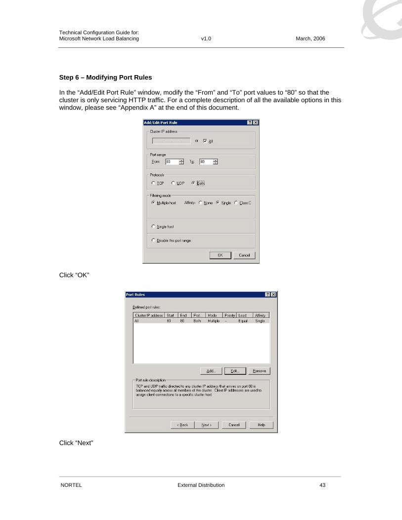
Step 6 – Modifying Port Rules In the “Add/Edit Port Rule” window, modify the “From” and “To” port values to “80” so that the cluster is only servicing HTTP traffic. For a complete description of all the available options in this window, please see “Appendix A” at the end of this document.
Click “OK”
Click “Next”

Technical Configuration Guide for: Microsoft Network Load Balancing v1.0 March, 2006
______________________________________________________________________________________________________
NORTEL External Distribution 31
Step 7 – Adding Labserver1 to the Cluster The “Connect” window allows us to add the first host that is to be a member of the cluster. In our example we have two Windows 2003 Advanced Servers named “Labserver1” and “Labserver2”. In this step we will add “Labserver1” and specify the “Network Adaptor” that will support the cluster. In the “Connect” window in the “Host” field, type in the name or IP Address of the first server that will be a member of the cluster. Click “Connect” and the “Network Load Balancing Manager” will attempt to contact the server.
If successful, the “Connection Status” field should show “Connected” and a list of available Network Adaptors will be listed in the “Interface name” table. Select the Interface that is to participate in the cluster and click on “Next”.

Technical Configuration Guide for: Microsoft Network Load Balancing v1.0 March, 2006
______________________________________________________________________________________________________
NORTEL External Distribution 32
Step 8 – Modifying Labserver1 Host Parameters The “Host Parameters” window defines the “Priority” or “Host ID” for the cluster host instance, the unique IP Address bound to the Network Adaptor and the “Initial host state”. For our example server “Labserver1” will be assigned as host “1”. We will retain the IP Addressing that was initially assigned to the Network Adaptor and we will use the default state of “Started”.
Click “Finish”

Technical Configuration Guide for: Microsoft Network Load Balancing v1.0 March, 2006
______________________________________________________________________________________________________
NORTEL External Distribution 33
Once the Cluster Wizard completes, the newly configured cluster “www.jclab.com” will be listed in the “Network Load Balancing Manager” window along with the host “Labserver1”. When the “Network Load Balancing Manager” has completed configuring the host, the host state should be listed as “Converged”.

Technical Configuration Guide for: Microsoft Network Load Balancing v1.0 March, 2006
______________________________________________________________________________________________________
NORTEL External Distribution 34
Step 9 – Adding Additional Hosts to the Cluster In the “Network Load Balancing Manager” application, right click on the cluster you just created (e.g. www.jclab.com) and select “Add Host to Cluster”. A new host can also be added to the cluster by selecting the “Cluster” menu and clicking on “Add Host”.

Technical Configuration Guide for: Microsoft Network Load Balancing v1.0 March, 2006
______________________________________________________________________________________________________
NORTEL External Distribution 35
Step 10 – Adding Labserver2 to the Cluster In the “Connect” window in the “Host” field, type in the name or IP Address of the second server that will be a member of the cluster. Click “Connect” and the “Network Load Balancing Manager” will attempt to contact the server.
If successful, the “Connection Status” field should show “Connected” and a list of available Network Adaptors will be listed in the “Interface name” table. Select the Interface that is to participate in the cluster and click on “Next”.

Technical Configuration Guide for: Microsoft Network Load Balancing v1.0 March, 2006
______________________________________________________________________________________________________
NORTEL External Distribution 36
Step 11 – Modifying Labserver2 Host Parameters The “Host Parameters” window defines the “Priority” or “Host ID” for the cluster host instance, the unique IP Address bound to the Network Adaptor and the “Initial host state”. For our example server “Labserver2” will be assigned as host “2”. We will retain the IP Addressing that was initially assigned to the Network Adaptor and we will use the default state of “Started”.
Click “Finished”

Technical Configuration Guide for: Microsoft Network Load Balancing v1.0 March, 2006
______________________________________________________________________________________________________
NORTEL External Distribution 37
Once the second host has been successfully added to the cluster, the host state will change to “Converged”.
Technical Configuration Guide for: Microsoft Network Load Balancing v1.0 March, 2006
______________________________________________________________________________________________________
NORTEL External Distribution 38
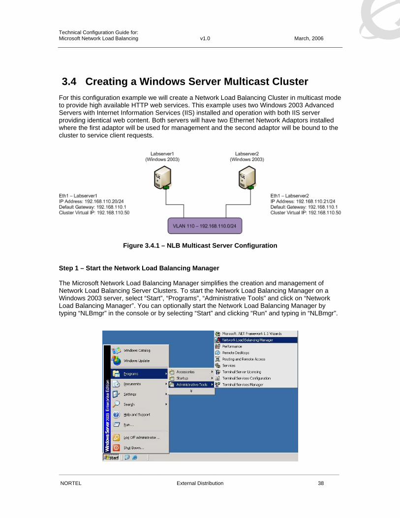
3.4 Creating a Windows Server Multicast Cluster For this configuration example we will create a Network Load Balancing Cluster in multicast mode to provide high available HTTP web services. This example uses two Windows 2003 Advanced Servers with Internet Information Services (IIS) installed and operation with both IIS server providing identical web content. Both servers will have two Ethernet Network Adaptors installed where the first adaptor will be used for management and the second adaptor will be bound to the cluster to service client requests.
Figure 3.4.1 – NLB Multicast Server Configuration Step 1 – Start the Network Load Balancing Manager The Microsoft Network Load Balancing Manager simplifies the creation and management of Network Load Balancing Server Clusters. To start the Network Load Balancing Manager on a Windows 2003 server, select “Start”, “Programs”, “Administrative Tools” and click on “Network Load Balancing Manager”. You can optionally start the Network Load Balancing Manager by typing “NLBmgr” in the console or by selecting “Start” and clicking “Run” and typing in “NLBmgr”.

Technical Configuration Guide for: Microsoft Network Load Balancing v1.0 March, 2006
______________________________________________________________________________________________________
NORTEL External Distribution 39
Network Load Balancing can optionally be configured on each individual server by modifying the Network Adaptors properties and binding the “Network Load Balancing” protocol to the Adaptor. This method is much more complex and does not provide visibility into the state of the cluster so for the purpose of this document the Network Load Balancing Manager will be used.
Step 2 – Creating a New Cluster In the “Network Load Balancing Manager” application, right click on “Network Load Balancing Clusters” and select “New Cluster”. A new cluster can also be created by selecting the “Cluster” menu and clicking on “New”.

Technical Configuration Guide for: Microsoft Network Load Balancing v1.0 March, 2006
______________________________________________________________________________________________________
NORTEL External Distribution 40
Step 3 – Modifying Cluster Parameters The “Cluster Parameters” window allows you to specify the Clusters Virtual IP Address, a full DNS name for the service and the Cluster operational mode. For this example we will use a Cluster Virtual IP Address of “192.168.110.50”. The Cluster Virtual IP Address is placed in the same IP subnet as the IP Addresses assigned to each of the second Ethernet Adaptors installed in each Server (see figure 3.2.1). We will enter in the full DNS name “www.jclab.com” which is configured on our DNS server and set the “Cluster operational mode” to “Multicast”. Click “Next”.
You can optionally enable “IGMP multicast” support which can be used to provide Multicast flood suppression. If the “IGMP multicast” option is enabled, please ensure that the IGMP version on the Windows 2003 server is changed to support IGMPv2. Click “Next”.

Technical Configuration Guide for: Microsoft Network Load Balancing v1.0 March, 2006
______________________________________________________________________________________________________
NORTEL External Distribution 41
Step 4 – Adding Additional Cluster IP Addresses The “Cluster IP Address” window allows you to bind additional Virtual IP Addresses to the Cluster. This can be useful in applications such as Web Servers where multiple sites are being hosted and each site requires a unique IP Address. For the purpose of this example we will be hosting a single Web site so no additional addresses are required.
Click “Next”

Technical Configuration Guide for: Microsoft Network Load Balancing v1.0 March, 2006
______________________________________________________________________________________________________
NORTEL External Distribution 42
Step 5 – Port Rules The “Port Rules” window allows you to specify how the traffic is handled by the hosts in the cluster. Port rules allow you to define which protocols the hosts in the cluster support, how the traffic is distributed between the hosts as well as weight each member in the cluster. The rules are very flexible and a single rule could be used to service a multiple applications or multiple rules can be used to limit applications to specific ports or hosts. For example a Web Server servicing HTTP & HTTPS requests could have a single rule with the port range set for 80 443. Alternatively two rules could be created with the first rule port range set for 80 80 and a second rule with the port range set for 443 443. By default all TCP / UDP traffic from 0 – 65535 received on the cluster Virtual IP Address will be distributed to all hosts in the cluster. For our example we are hosting a Web Server so we will modify the default port rules so that only HTTP traffic is serviced by the hosts. To modify the default rule, click on “Edit”
Technical Configuration Guide for: Microsoft Network Load Balancing v1.0 March, 2006
______________________________________________________________________________________________________
NORTEL External Distribution 43
Step 6 – Modifying Port Rules In the “Add/Edit Port Rule” window, modify the “From” and “To” port values to “80” so that the cluster is only servicing HTTP traffic. For a complete description of all the available options in this window, please see “Appendix A” at the end of this document.
Click “OK”
Click “Next”

Technical Configuration Guide for: Microsoft Network Load Balancing v1.0 March, 2006
______________________________________________________________________________________________________
NORTEL External Distribution 44
Step 7 – Adding Labserver1 to the Cluster The “Connect” window allows us to add the first host that is to be a member of the cluster. In our example we have two Windows 2003 Advanced Servers named “Labserver1” and “Labserver2”. In this step we will add “Labserver1” and specify the “Network Adaptor” that will support the cluster. In the “Connect” window in the “Host” field, type in the name or IP Address of the first server that will be a member of the cluster. Click “Connect” and the “Network Load Balancing Manager” will attempt to contact the server.
If successful, the “Connection Status” field should show “Connected” and a list of available Network Adaptors will be listed in the “Interface name” table. Select the Interface that is to participate in the cluster and click on “Next”.

Technical Configuration Guide for: Microsoft Network Load Balancing v1.0 March, 2006
______________________________________________________________________________________________________
NORTEL External Distribution 45
Step 8 – Modifying Labserver1 Host Parameters The “Host Parameters” window defines the “Priority” or “Host ID” for the cluster host instance, the unique IP Address bound to the Network Adaptor and the “Initial host state”. For our example server “Labserver1” will be assigned as host “1”. We will retain the IP Addressing that was initially assigned to the Network Adaptor and we will use the default state of “Started”.
Click “Finish”
Technical Configuration Guide for: Microsoft Network Load Balancing v1.0 March, 2006
______________________________________________________________________________________________________
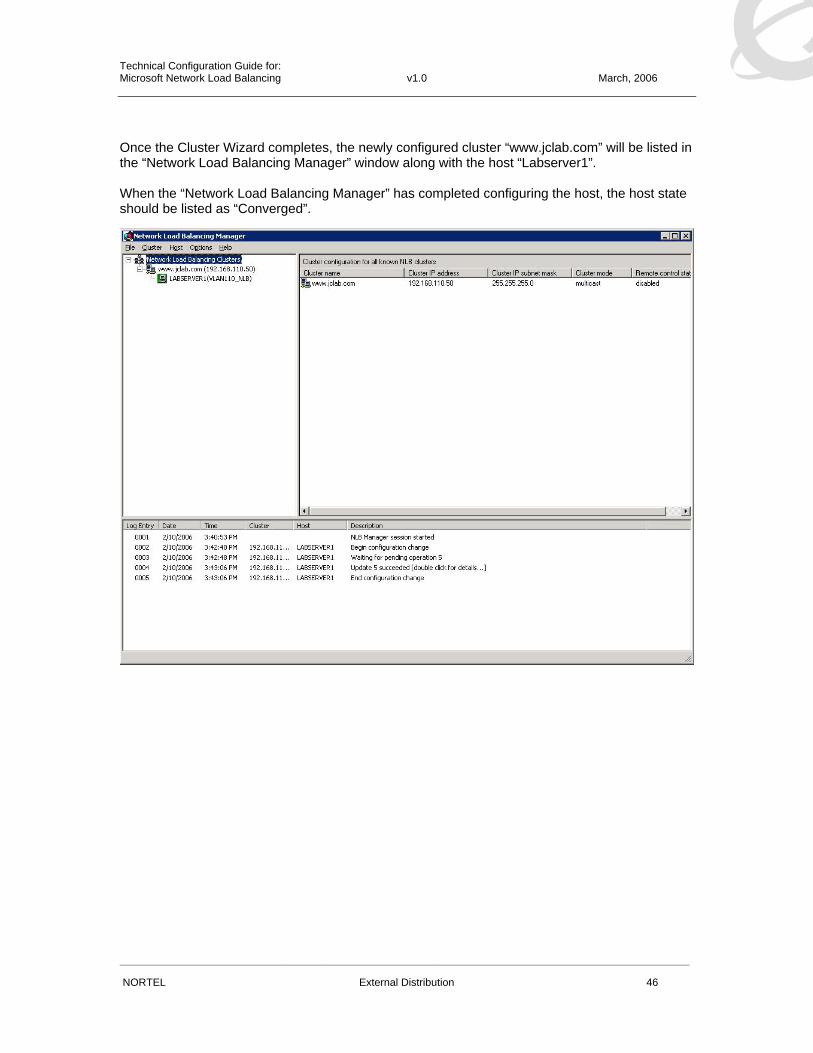
NORTEL External Distribution 46
Once the Cluster Wizard completes, the newly configured cluster “www.jclab.com” will be listed in the “Network Load Balancing Manager” window along with the host “Labserver1”. When the “Network Load Balancing Manager” has completed configuring the host, the host state should be listed as “Converged”.

Technical Configuration Guide for: Microsoft Network Load Balancing v1.0 March, 2006
______________________________________________________________________________________________________
NORTEL External Distribution 47
Step 9 – Adding Additional Hosts to the Cluster In the “Network Load Balancing Manager” application, right click on the cluster you just created (e.g. www.jclab.com) and select “Add Host to Cluster”. A new host can also be added to the cluster by selecting the “Cluster” menu and clicking on “Add Host”.
Technical Configuration Guide for: Microsoft Network Load Balancing v1.0 March, 2006
______________________________________________________________________________________________________
NORTEL External Distribution 48
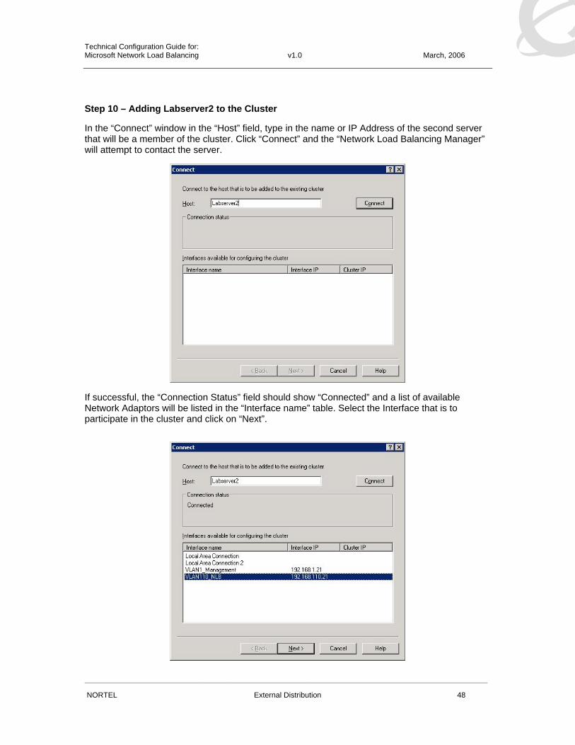
Step 10 – Adding Labserver2 to the Cluster In the “Connect” window in the “Host” field, type in the name or IP Address of the second server that will be a member of the cluster. Click “Connect” and the “Network Load Balancing Manager” will attempt to contact the server.
If successful, the “Connection Status” field should show “Connected” and a list of available Network Adaptors will be listed in the “Interface name” table. Select the Interface that is to participate in the cluster and click on “Next”.
Technical Configuration Guide for: Microsoft Network Load Balancing v1.0 March, 2006
______________________________________________________________________________________________________
NORTEL External Distribution 49
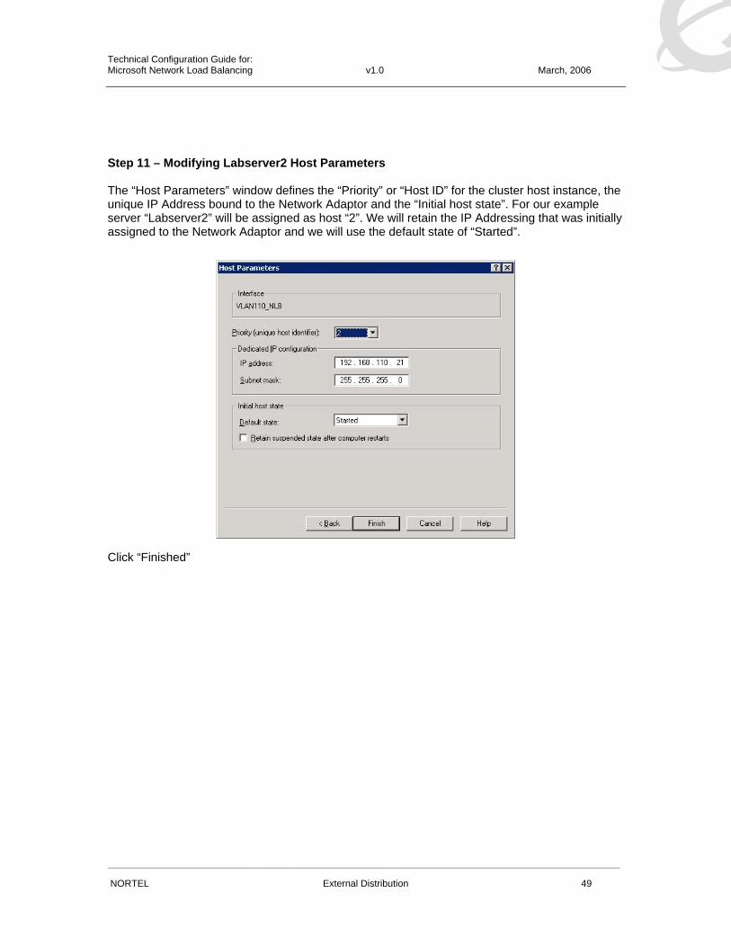
Step 11 – Modifying Labserver2 Host Parameters The “Host Parameters” window defines the “Priority” or “Host ID” for the cluster host instance, the unique IP Address bound to the Network Adaptor and the “Initial host state”. For our example server “Labserver2” will be assigned as host “2”. We will retain the IP Addressing that was initially assigned to the Network Adaptor and we will use the default state of “Started”.
Click “Finished”

Technical Configuration Guide for: Microsoft Network Load Balancing v1.0 March, 2006
______________________________________________________________________________________________________
NORTEL External Distribution 50
Once the second host has been successfully added to the cluster, the host state will change to “Converged”.

Technical Configuration Guide for: Microsoft Network Load Balancing v1.0 March, 2006
______________________________________________________________________________________________________
NORTEL External Distribution 51
3.5 Ethernet Switch Configuration Example The following configuration example demonstrates how to configure a standalone Nortel Ethernet Stackable Switch to support a Microsoft Network Load Balancing cluster of servers running in unicast or multicast modes.
In this example the Network Load Balancing cluster of servers and clients will be located on a single IP subnet (VLAN) which will represent a typical small office deployment.
As described in previous sections, no special switch configuration is required, however for this example we will enable IGMP snooping and proxy on the switch to provide multicast flood suppression.
Figure 3.5 – ES 470-24T Example Topology
3.5.1 ES 470-24T – Configuration For this example we will configure an Ethernet Switch 470-24T as follows:
1. Configure a management IP address of 192.168.1.10/24
2. Enable IGMPv2 snooping and proxy to provide NLB multicast suppression
From the Ethernet Switch Main Menu, select “Command Line Interface” to access the Nortel CLI.
1. At the CLI prompt, enter the configuration mode:
• 470-24T>enable
• 470-24T# configure terminal

Technical Configuration Guide for: Microsoft Network Load Balancing v1.0 March, 2006
______________________________________________________________________________________________________
NORTEL External Distribution 52
2. Create a IP address on the Ethernet Switch for management:
• 470-24T(config)# ip address switch 192.168.1.10 netmask 255.255.255.0
3. Verify IP addressing:
• 470-24T (config)# show ip BootP Mode: BootP Disabled
Configured In Use Last BootP
--------------- --------------- ---------------
Stack IP Address: 0.0.0.0 0.0.0.0
Switch IP Address: 192.168.1.10 192.168.1.10 0.0.0.0
Subnet Mask: 255.255.255.0 255.255.255.0 0.0.0.0
Default Gateway: 0.0.0.0 0.0.0.0 0.0.0.0
4. At the CLI prompt, enter the configuration mode:
• 470-24T>enable
• 470-24T# configure terminal
5. Enable IGMP snooping and proxy on VLAN 1:
• 470-24T(config)# vlan igmp 1 snooping enable
• 470-24T(config)# vlan igmp 1 proxy enable
6. Verify IGMP snooping and proxy are enabled on VLAN 1:
• 470-24T(config)# show vlan igmp 1
Snooping: Enabled
Proxy: Enabled
Robust Value: 2
Query Time: 125 seconds
IGMPv1 Static Router Ports: NONE
IGMPv2 Static Router Ports: NONE
7. Verify IGMP is suppressing the multicast flows to the server ports:
• 470-24T(config)# show vlan multicast membership 1
Multicast Group Address Port
----------------------- ----
239.255.1.50 1
239.255.1.50 3

Technical Configuration Guide for: Microsoft Network Load Balancing v1.0 March, 2006
______________________________________________________________________________________________________
NORTEL External Distribution 53
3.6 ERS 1600 Configuration Example The following configuration example demonstrates how to configure a centralized Nortel Ethernet Routing Switch 1600 to support a multiple subnet environment where the Microsoft Network Load Balancing cluster of servers and clients are connected to a subtended Layer 2 switches and are placed in separate IP subnets (VLANs).
Figure 3.6 – ERS 1612G Example Topology
3.6.1 ERS 1612G – Configuration For the first step we will configure an Ethernet Routing Switch 1600 as follows:
1. Create VLAN 2 to support clients (VLAN 1 is enabled by default)
2. Enable 802.1Q tagging on ports 1 – 4
3. Assign ports 1 – 2 to VLAN 1
4. Assign port 3 – 4 to VLAN 2
5. Assign a IP address of 192.168.1.1/24 to VLAN 1
6. Assign a IP address of 192.168.2.1/24 to VLAN 2
7. Force speed and duplex on ports 3 – 4 to 1000Mbps FDX to support the ES 470-24T
8. Create a Multi-Link Trunk with ports 1 – 2 to connect the ERS 5510-24T server switch
9. Create a Multi-Link Trunk with ports 3 – 4 to connect the ES 470-24T client switch
10. Create a static ARP entry to support NLB multicast mode
Technical Configuration Guide for: Microsoft Network Load Balancing v1.0 March, 2006
______________________________________________________________________________________________________
NORTEL External Distribution 54
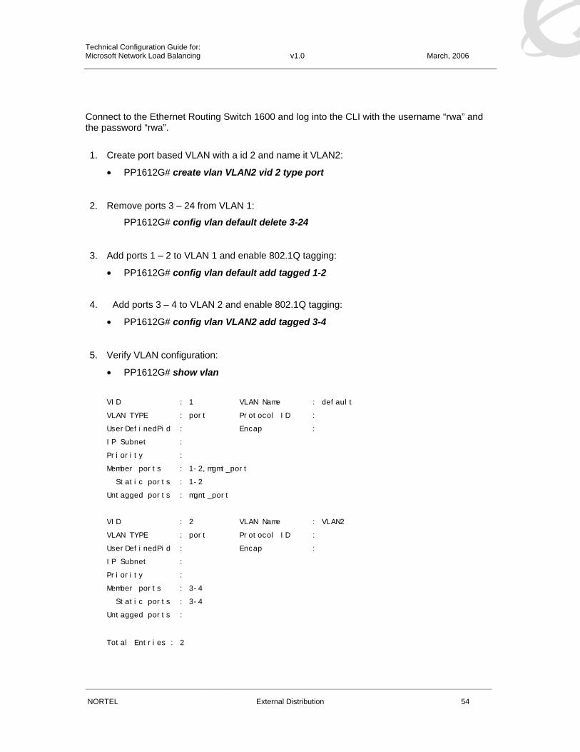
Connect to the Ethernet Routing Switch 1600 and log into the CLI with the username “rwa” and the password “rwa”.
1. Create port based VLAN with a id 2 and name it VLAN2:
• PP1612G# create vlan VLAN2 vid 2 type port
2. Remove ports 3 – 24 from VLAN 1:
PP1612G# config vlan default delete 3-24
3. Add ports 1 – 2 to VLAN 1 and enable 802.1Q tagging:
• PP1612G# config vlan default add tagged 1-2
4. Add ports 3 – 4 to VLAN 2 and enable 802.1Q tagging:
• PP1612G# config vlan VLAN2 add tagged 3-4
5. Verify VLAN configuration:
• PP1612G# show vlan
VID : 1 VLAN Name : default
VLAN TYPE : port Protocol ID :
UserDefinedPid : Encap :
IP Subnet :
Priority :
Member ports : 1-2,mgmt_port
Static ports : 1-2
Untagged ports : mgmt_port
VID : 2 VLAN Name : VLAN2
VLAN TYPE : port Protocol ID :
UserDefinedPid : Encap :
IP Subnet :
Priority :
Member ports : 3-4
Static ports : 3-4
Untagged ports :
Total Entries : 2

Technical Configuration Guide for: Microsoft Network Load Balancing v1.0 March, 2006
______________________________________________________________________________________________________
NORTEL External Distribution 55
6. Change the IP address for VLAN 1 to 192.168.1.1 and set the subnet mask to 255.255.255.0:
• PP1612G# config ipif System ipaddress 192.168.1.1/24
7. Create a IP Interface named VLAN 2_IF, set the IP address to 192.168.2.1 and the subnet mask to 255.255.255.0 and tie it to the VLAN named VLAN2:
• PP1612G# create ipif VLAN2_IF 192.168.2.1/24 VLAN2
8. Verify IP Interface configuration:
• PP1612G# show ipif
IP Interface Settings
Interface Name : System
IP Address : 192.168.1.1 (MANUAL)
Subnet Mask : 255.255.255.0
VLAN Name : default
Admin. State : Enabled
Interface Status : Link DOWN
Directed-Broadcast: Enabled
Member Ports : 1-2,mgmt_port
Interface Name : VLAN2_IF
IP Address : 192.168.2.1 (MANUAL)
Subnet Mask : 255.255.255.0
VLAN Name : VLAN2
Admin. State : Enabled
Interface Status : Link DOWN
Directed-Broadcast: Enabled
Member Ports : 3-4
Total Entries : 2
9. Ports 3 – 4 will connect to a ES 470-24T so we will need to force the speed and duplex on the ports to 1000Mbps Full Duplex:
• PP1612G# config ports 3-4 speed 1000_full

Technical Configuration Guide for: Microsoft Network Load Balancing v1.0 March, 2006
______________________________________________________________________________________________________
NORTEL External Distribution 56
10. Verify Ports 3 – 4 speed and duplex settings:
• PP1612G# show ports 3-4
Port Port Settings Connection Address
State Speed/Duplex/FlowCtrl Speed/Duplex/FlowCtrl Learning
---- -------- --------------------- --------------------- --------
3 Enabled 1000M/Full/Disabled Link Down Enabled
4 Enabled 1000M/Full/Disabled Link Down Enabled
11. Create Multi-Link Trunking group 1 and add ports 1 - 2:
• PP1612G# create link_aggregation group_id 1
• PP1612G# config link_aggregation group_id 1 master_port 1 ports 1-2
• PP1612G# config link_aggregation group_id 1 state enabled
12. Create Multi-Link Trunking group 2 and add ports 3 - 4:
• PP1612G# create link_aggregation group_id 2
• PP1612G# config link_aggregation group_id 2 master_port 3 ports 3-4
• PP1612G# config link_aggregation group_id 2 state enabled
13. Verify Multi-Link Trunking configuration:
• PP1612G# show link_aggregation
Group ID : 1
Master Port : 1
Member Port : 1-2
Status : Enabled
Flooding Port : 1
BPDU 8600 Interop : Disabled
Group ID : 2
Master Port : 3
Member Port : 3-4
Status : Enabled
Flooding Port : 3
BPDU 8600 Interop : Disabled
Technical Configuration Guide for: Microsoft Network Load Balancing v1.0 March, 2006
______________________________________________________________________________________________________
NORTEL External Distribution 57
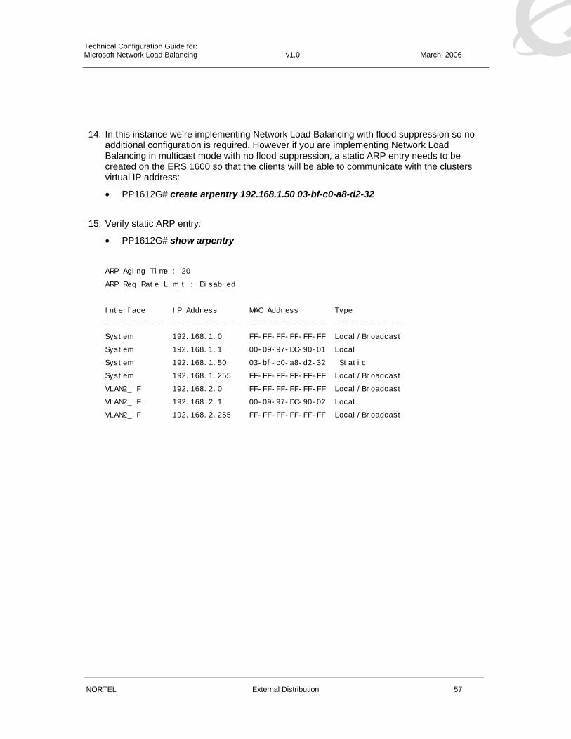
14. In this instance we’re implementing Network Load Balancing with flood suppression so no additional configuration is required. However if you are implementing Network Load Balancing in multicast mode with no flood suppression, a static ARP entry needs to be created on the ERS 1600 so that the clients will be able to communicate with the clusters virtual IP address:
• PP1612G# create arpentry 192.168.1.50 03-bf-c0-a8-d2-32
15. Verify static ARP entry:
• PP1612G# show arpentry
ARP Aging Time : 20
ARP Req Rate Limit : Disabled
Interface IP Address MAC Address Type
------------- --------------- ----------------- ---------------
System 192.168.1.0 FF-FF-FF-FF-FF-FF Local/Broadcast
System 192.168.1.1 00-09-97-DC-90-01 Local
System 192.168.1.50 03-bf-c0-a8-d2-32 Static
System 192.168.1.255 FF-FF-FF-FF-FF-FF Local/Broadcast
VLAN2_IF 192.168.2.0 FF-FF-FF-FF-FF-FF Local/Broadcast
VLAN2_IF 192.168.2.1 00-09-97-DC-90-02 Local
VLAN2_IF 192.168.2.255 FF-FF-FF-FF-FF-FF Local/Broadcast

Technical Configuration Guide for: Microsoft Network Load Balancing v1.0 March, 2006
______________________________________________________________________________________________________
NORTEL External Distribution 58
3.6.2 ERS 5510-24T – Configuration For the first step we will configure an Ethernet Routing Switch 5510-24T as follows:
1. Configure a management IP address of 192.168.1.10/24 and default gateway 192.168.1.1
2. Enable 802.1Q tagging on ports 23 – 24
3. Create a Multi-Link Trunk with ports 23 – 24 to connect to the ERS 1612G
4. Enable IGMPv2 snooping and proxy to provide NLB multicast suppression
From the Ethernet Switch Main Menu, select “Command Line Interface” to access the Nortel CLI.
1. At the CLI prompt, enter the configuration mode:
• ERS5510-24T>enable
• ERS5510-24T# configure terminal
2. Create a IP address on the Ethernet Switch for management:
• ERS5510-24T(config)# ip address switch 192.168.1.10 netmask 255.255.255.0
3. Configure a default gateway:
• ERS5510-24T(config)# ip default-gateway 192.168.1.1
4. Verify IP addressing:
• ERS5510-24T(config)# show ip BootP Mode: BootP Disabled
Configured In Use Last BootP
--------------- --------------- ---------------
Stack IP Address: 0.0.0.0 0.0.0.0
Switch IP Address: 192.168.1.10 192.168.1.10 0.0.0.0
Subnet Mask: 255.255.255.0 255.255.255.0 0.0.0.0
Default Gateway: 192.168.1.1 192.168.1.1 0.0.0.0
5. Enable 802.1Q tagging on ports 23-24:
• ERS5510-24T(config)# vlan ports 23-24 tagging tagall
Technical Configuration Guide for: Microsoft Network Load Balancing v1.0 March, 2006
______________________________________________________________________________________________________
NORTEL External Distribution 59
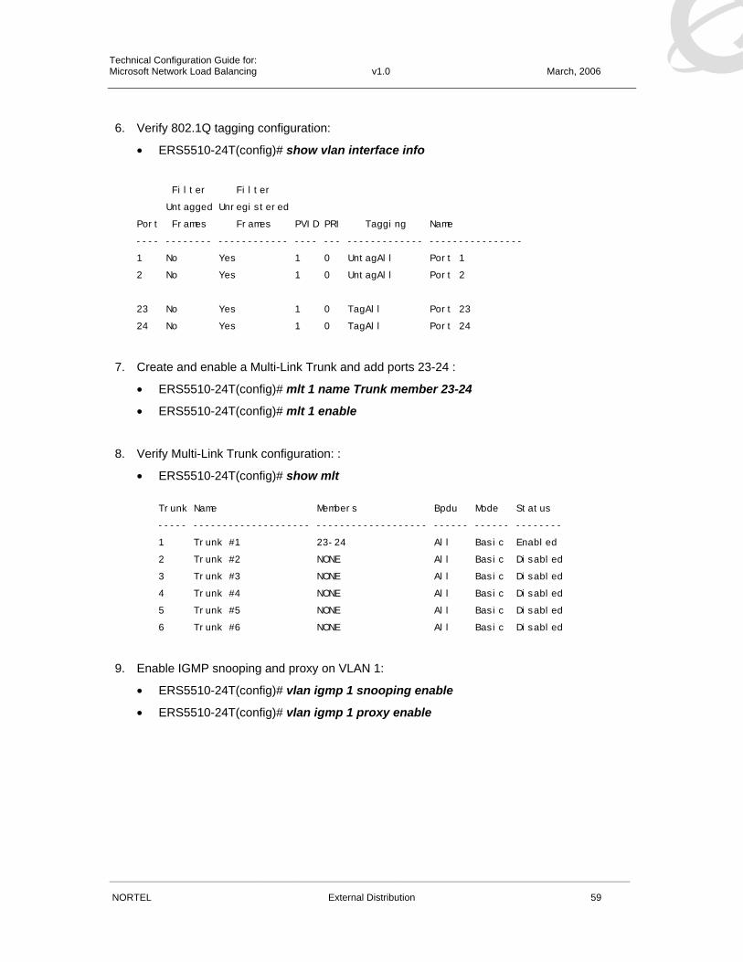
6. Verify 802.1Q tagging configuration:
• ERS5510-24T(config)# show vlan interface info
Filter Filter
Untagged Unregistered
Port Frames Frames PVID PRI Tagging Name
---- -------- ------------ ---- --- ------------- ----------------
1 No Yes 1 0 UntagAll Port 1
2 No Yes 1 0 UntagAll Port 2
23 No Yes 1 0 TagAll Port 23
24 No Yes 1 0 TagAll Port 24
7. Create and enable a Multi-Link Trunk and add ports 23-24 :
• ERS5510-24T(config)# mlt 1 name Trunk member 23-24
• ERS5510-24T(config)# mlt 1 enable
8. Verify Multi-Link Trunk configuration: :
• ERS5510-24T(config)# show mlt Trunk Name Members Bpdu Mode Status
----- -------------------- ------------------- ------ ------ --------
1 Trunk #1 23-24 All Basic Enabled
2 Trunk #2 NONE All Basic Disabled
3 Trunk #3 NONE All Basic Disabled
4 Trunk #4 NONE All Basic Disabled
5 Trunk #5 NONE All Basic Disabled
6 Trunk #6 NONE All Basic Disabled
9. Enable IGMP snooping and proxy on VLAN 1:
• ERS5510-24T(config)# vlan igmp 1 snooping enable
• ERS5510-24T(config)# vlan igmp 1 proxy enable

Technical Configuration Guide for: Microsoft Network Load Balancing v1.0 March, 2006
______________________________________________________________________________________________________
NORTEL External Distribution 60
10. Verify IGMP snooping and proxy are enabled on VLAN 1:
• ERS5510-24T(config)# show vlan igmp 1
Snooping: Enabled
Proxy: Enabled
Robust Value: 2
Query Time: 125 seconds
IGMPv1 Static Router Ports: NONE
IGMPv2 Static Router Ports: NONE
11. Verify IGMP is suppressing the multicast flows to the server ports:
• ERS5510-24T(config)# show vlan multicast membership 1
Multicast Group Address Port
----------------------- ----
239.255.1.50 1
239.255.1.50 3

Technical Configuration Guide for: Microsoft Network Load Balancing v1.0 March, 2006
______________________________________________________________________________________________________
NORTEL External Distribution 61
3.6.3 ES 470-24T – Configuration For the first step we will configure an Ethernet Switch 470-24T as follows:
1. Configure a management IP address of 192.168.2.10/24 and default gateway 192.168.2.1
2. Enable Auto-PVID
3. Create VLAN 2 and assign is as the management VLAN
4. Assign ports 1 – 24 to VLAN 2
5. Enable 802.1Q tagging on ports 23 – 24
6. Create a Multi-Link Trunk with ports 23 – 24 to connect to the ERS 1612G
From the Ethernet Switch Main Menu, select “Command Line Interface” to access the Nortel CLI.
1. At the CLI prompt, enter the configuration mode:
• ES470-24T>enable
• ES470-24T# configure terminal
2. Create a IP address on the Ethernet Switch for management:
• ES470-24T(config)# ip address switch 192.168.2.10 netmask 255.255.255.0
3. Configure a default gateway:
• ES470-24T(config)# ip default-gateway 192.168.2.1
4. Verify IP addressing:
• ES470-24T(config)# show ip BootP Mode: BootP Disabled
Configured In Use Last BootP
--------------- --------------- ---------------
Stack IP Address: 0.0.0.0 0.0.0.0
Switch IP Address: 192.168.2.10 192.168.2.10 0.0.0.0
Subnet Mask: 255.255.255.0 255.255.255.0 0.0.0.0
Default Gateway: 192.168.2.1 192.168.2.1 0.0.0.0
Technical Configuration Guide for: Microsoft Network Load Balancing v1.0 March, 2006
______________________________________________________________________________________________________
NORTEL External Distribution 62
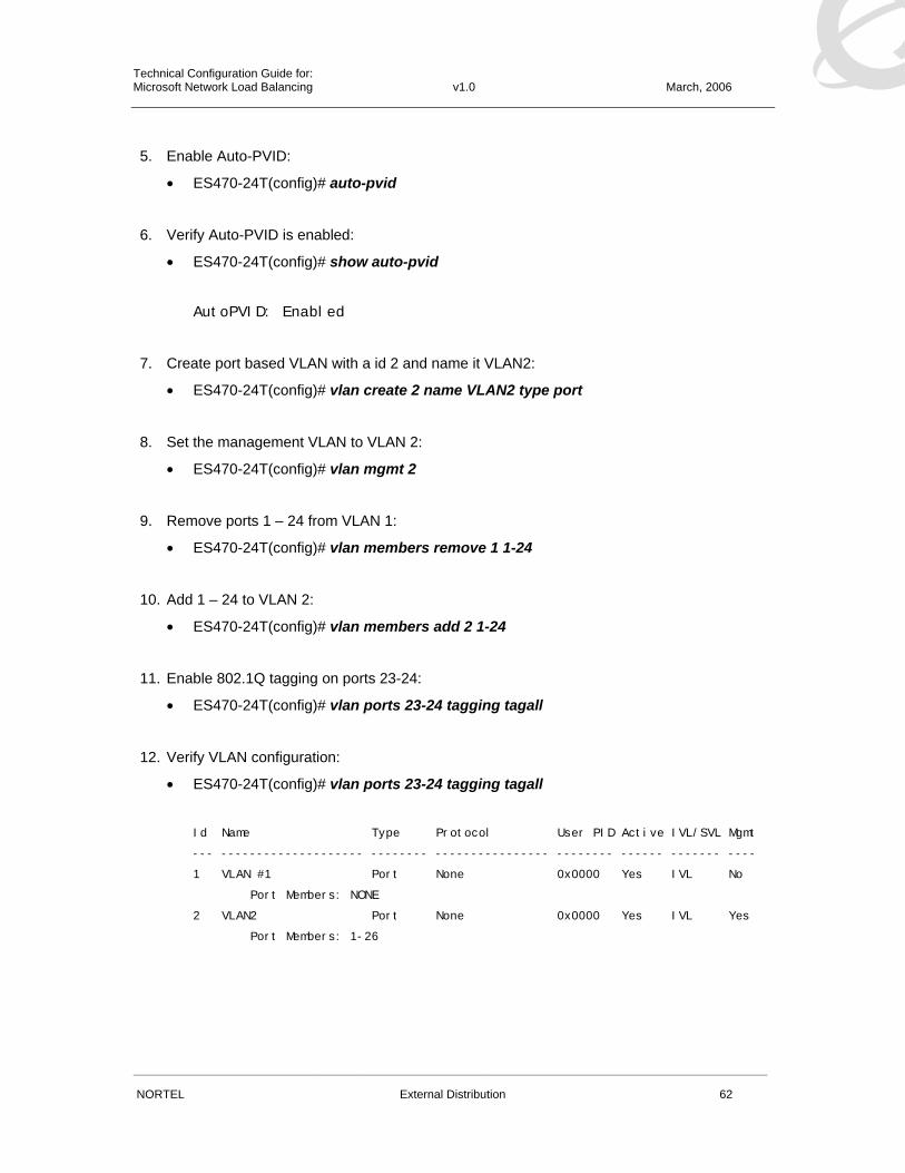
5. Enable Auto-PVID:
• ES470-24T(config)# auto-pvid
6. Verify Auto-PVID is enabled:
• ES470-24T(config)# show auto-pvid
AutoPVID: Enabled
7. Create port based VLAN with a id 2 and name it VLAN2:
• ES470-24T(config)# vlan create 2 name VLAN2 type port
8. Set the management VLAN to VLAN 2:
• ES470-24T(config)# vlan mgmt 2
9. Remove ports 1 – 24 from VLAN 1:
• ES470-24T(config)# vlan members remove 1 1-24
10. Add 1 – 24 to VLAN 2:
• ES470-24T(config)# vlan members add 2 1-24
11. Enable 802.1Q tagging on ports 23-24:
• ES470-24T(config)# vlan ports 23-24 tagging tagall
12. Verify VLAN configuration:
• ES470-24T(config)# vlan ports 23-24 tagging tagall Id Name Type Protocol User PID Active IVL/SVL Mgmt
--- -------------------- -------- ---------------- -------- ------ ------- ----
1 VLAN #1 Port None 0x0000 Yes IVL No
Port Members: NONE
2 VLAN2 Port None 0x0000 Yes IVL Yes
Port Members: 1-26

Technical Configuration Guide for: Microsoft Network Load Balancing v1.0 March, 2006
______________________________________________________________________________________________________
NORTEL External Distribution 63
13. Verify 802.1Q tagging configuration:
• ES470-24T(config)# show vlan interface info
Filter Filter
Untagged Unregistered
Port Frames Frames PVID PRI Tagging Name
---- -------- ------------ ---- --- ------------- ----------------
1 No Yes 2 0 UntagAll Port 1
2 No Yes 2 0 UntagAll Port 2
23 No Yes 2 0 TagAll Port 23
24 No Yes 2 0 TagAll Port 24
14. Verify VLAN assignment:
• ES470-24T(config)# show vlan interface vids
Port VLAN VLAN Name VLAN VLAN Name VLAN VLAN Name
---- ---- ---------------- ---- ---------------- ---- ----------------
1 2 VLAN2
---- ---- ---------------- ---- ---------------- ---- ----------------
2 2 VLAN2
---- ---- ---------------- ---- ---------------- ---- ----------------
---- ---- ---------------- ---- ---------------- ---- ----------------
23 2 VLAN2
---- ---- ---------------- ---- ---------------- ---- ----------------
24 2 VLAN2
---- ---- ---------------- ---- ---------------- ---- ----------------
15. Create and enable a Multi-Link Trunk and add ports 23-24 :
• ES470-24T(config)# mlt 1 name Trunk member 23-24
• ES470-24T(config)# mlt 1 enable
16. Verify Multi-Link Trunk configuration: :
• ES470-24T(config)# show mlt Trunk Name Members Bpdu Mode Status
----- -------------------- ------------------- ------ ------ --------
1 Trunk #1 23-24 All Basic Enabled
2 Trunk #2 NONE All Basic Disabled
6 Trunk #6 NONE All Basic Disabled

Technical Configuration Guide for: Microsoft Network Load Balancing v1.0 March, 2006
______________________________________________________________________________________________________
NORTEL External Distribution 64
3.7 ERS 5500 Configuration Example The following configuration example demonstrates how to configure a centralized Nortel Ethernet Routing Switch 5530-24TFD to support a multiple subnet environment where the Microsoft Network Load Balancing cluster of servers and clients are connected to a subtended Layer 2 switches and are placed in separate IP subnets (VLANs).
Figure 3.7 – ERS 5530-24TFD Example Topology
3.7.1 ERS 5530-24TFD – Configuration For the first step we will configure an Ethernet Routing Switch 5530-24TFD as follows:
1. Create VLAN 2 to support clients (VLAN 1 is enabled by default)
2. Enable 802.1Q tagging on ports 13 – 16
3. Assign ports 13 – 14 to VLAN 1
4. Assign ports 15 – 16 to VLAN 2
5. Assign a IP address of 192.168.1.1/24 to VLAN 1
6. Assign a IP address of 192.168.2.1/24 to VLAN 2
7. Force speed and duplex on ports 15 – 16 to 1000Mbps FDX to support the ES 470-24T
8. Create a Multi-Link Trunk with ports 13 – 14 to connect the ERS 5510-24T server switch
9. Create a Multi-Link Trunk with ports 15 – 16 to connect the ES 470-24T client switch
10. Create a static ARP entry to support NLB multicast mode

Technical Configuration Guide for: Microsoft Network Load Balancing v1.0 March, 2006
______________________________________________________________________________________________________
NORTEL External Distribution 65
From the Ethernet Switch Main Menu, select “Command Line Interface” to access the Nortel CLI.
1. At the CLI prompt, enter the configuration mode:
• ERS5530-24TFD>enable
• ERS5530-24TFD# configure terminal
2. Enable IP Routing:
• ERS5530-24TFD(config)# ip routing
3. Verify IP Routing is enabled:
• ERS5530-24TFD(config)# show ip routing
IP Routing is enabled
IP ARP life time is 21600 seconds
4. Enable Auto-PVID:
• ERS5530-24TFD(config)# auto-pvid
5. Verify Auto-PVID is enabled:
• ERS5530-24TFD(config)# show auto-pvid
AutoPVID: Enabled
6. Create port based VLAN with a id 2 and name it VLAN2:
• ERS5530-24TFD(config)# vlan create 2 name VLAN2 type port
7. Create a IP address and mask on VLAN 1:
• ERS5530-24TFD(config)# interface vlan 1
• ERS5530-24TFD(config-if)# ip address 192.168.1.1 255.255.255.0
8. Create a IP address and mask on VLAN 2:
• ERS5530-24TFD(config-if)# interface vlan 2
• ERS5530-24TFD(config-if)# ip address 192.168.2.1 255.255.255.0
• ERS5530-24TFD(config-if)# exit

Technical Configuration Guide for: Microsoft Network Load Balancing v1.0 March, 2006
______________________________________________________________________________________________________
NORTEL External Distribution 66
9. Verify IP addressing:
• ERS5530-24TFD(config)# show vlan ip
Id ifIndex Address Mask MacAddress Offset
1 10001 192.168.1.1 255.255.255.0 00:0C:F8:64:04:40 1
2 10002 192.168.2.1 255.255.255.0 00:0C:F8:64:04:41 2
10. Remove ports 15 – 16 from VLAN 1:
• ERS5530-24TFD(config)# vlan members remove 1 15-16
11. Add 15 – 16 to VLAN 2:
• ERS5530-24TFD(config)# vlan members add 2 15-16
12. Enable 802.1Q tagging on ports 13-16:
• ERS5530-24TFD(config)# vlan ports 13-16 tagging tagall
13. Verify 802.1Q tagging configuration:
• ERS5530-24TFD(config)# show vlan interface info
Filter Filter
Untagged Unregistered
Port Frames Frames PVID PRI Tagging Name
---- -------- ------------ ---- --- ------------- ----------------
1 No Yes 1 0 UntagAll Port 1
13 No Yes 1 0 TagAll Port 13
14 No Yes 1 0 TagAll Port 14
15 No Yes 2 0 TagAll Port 15
16 No Yes 2 0 TagAll Port 16
16. Ports 14 – 15 will connect to a ES 470-24T so we will need to force the speed and duplex on the ports to 1000Mbps Full Duplex:
• ERS5530-24TFD(config)# interface fastEthernet 14-15
• ERS5530-24TFD(config-if)# speed 1000
• ERS5530-24TFD(config-if)# duplex full
• ERS5530-24TFD(config-if)# exit

Technical Configuration Guide for: Microsoft Network Load Balancing v1.0 March, 2006
______________________________________________________________________________________________________
NORTEL External Distribution 67
17. Verify Ports 23 – 24 speed and duplex settings:
• ERS5530-24TFD(config)# show interfaces 23-24
Status Auto Flow
Port Trunk Admin Oper Link LinkTrap Negotiation Speed Duplex Control
---- ----- ------- ---- ---- -------- ----------- -------- ------ -------
23 Enable Down Down Enabled Disabled 1000Mbps Full Disable
24 Enable Down Down Enabled Disabled 1000Mbps Full Disable
14. Create and enable a Multi-Link Trunk and add ports 13-14 :
• ERS5530-24TFD(config)# mlt 1 name Trunk_1 member 13-14
• ERS5530-24TFD(config)# mlt 1 enable
15. Create and enable a Multi-Link Trunk and add ports 15-16 :
• ERS5530-24TFD(config)# mlt 2 name Trunk_2 member 15-16
• ERS5530-24TFD(config)# mlt 2 enable
16. Verify Multi-Link Trunk configuration: :
• ERS5530-24TFD(config)# show mlt Trunk Name Members Bpdu Mode Status
----- -------------------- ------------------- ------ ------ --------
1 Trunk_1 13-14 All Basic Enabled
2 Trunk_2 15-16 All Basic Enabled
6 Trunk #6 NONE All Basic Disabled
17. Create a static ARP entry mapping the clusters unicast virtual IP address 192.168.1.50 to the clusters multicast MAC address 01:00:5e:7f:d2:32:
• ERS5530-24TFD(config)# ip arp 192.168.110.50 01-00-5e-7f-d2-32 vid 1

Technical Configuration Guide for: Microsoft Network Load Balancing v1.0 March, 2006
______________________________________________________________________________________________________
NORTEL External Distribution 68
18. Verify ARP table:
• ERS5530-24TFD(config)# show ip arp
===============================================================================
IP ARP
===============================================================================
IP Address Age (min) MAC Address VLAN-Unit/Port/Trunk Flags
-------------------------------------------------------------------------------
192.168.2.255 0 ff:ff:ff:ff:ff:ff VLAN#2 LB
192.168.1.255 0 ff:ff:ff:ff:ff:ff VLAN#1 LB
192.168.2.1 0 00:0c:f8:64:04:41 VLAN#2 L
192.168.1.1 0 00:0c:f8:64:04:40 VLAN#1 L
192.168.2.0 0 ff:ff:ff:ff:ff:ff VLAN#2 LB
192.168.1.0 0 ff:ff:ff:ff:ff:ff VLAN#1 LB
192.168.1.50 0 01:00:5e:7f:d2:32 VLAN#1-Trunk_1 S
-------------------------------------------------------------------------------
Flags Legend:
S=Static, D=Dynamic, L=Local, B=Broadcast

Technical Configuration Guide for: Microsoft Network Load Balancing v1.0 March, 2006
______________________________________________________________________________________________________
NORTEL External Distribution 69
3.7.2 ERS 5510-24T – Configuration For the first step we will configure an Ethernet Routing Switch 5510-24T as follows:
1. Configure a management IP address of 192.168.1.10/24 and default gateway 192.168.1.1
2. Enable 802.1Q tagging on ports 23 – 24
3. Create a Multi-Link Trunk with ports 23 – 24 to connect to the ERS 5530-24TFD
4. Enable IGMPv2 snooping and proxy to provide NLB multicast suppression
From the Ethernet Switch Main Menu, select “Command Line Interface” to access the Nortel CLI.
1. At the CLI prompt, enter the configuration mode:
• ERS5510-24T>enable
• ERS5510-24T# configure terminal
2. Create a IP address on the Ethernet Switch for management:
• ERS5510-24T(config)# ip address switch 192.168.1.10 netmask 255.255.255.0
3. Configure a default gateway:
• ERS5510-24T(config)# ip default-gateway 192.168.1.1
4. Verify IP addressing:
• ERS5510-24T(config)# show ip BootP Mode: BootP Disabled
Configured In Use Last BootP
--------------- --------------- ---------------
Stack IP Address: 0.0.0.0 0.0.0.0
Switch IP Address: 192.168.1.10 192.168.1.10 0.0.0.0
Subnet Mask: 255.255.255.0 255.255.255.0 0.0.0.0
Default Gateway: 192.168.1.1 192.168.1.1 0.0.0.0
5. Enable 802.1Q tagging on ports 23-24:
• ERS5510-24T(config)# vlan ports 23-24 tagging tagall
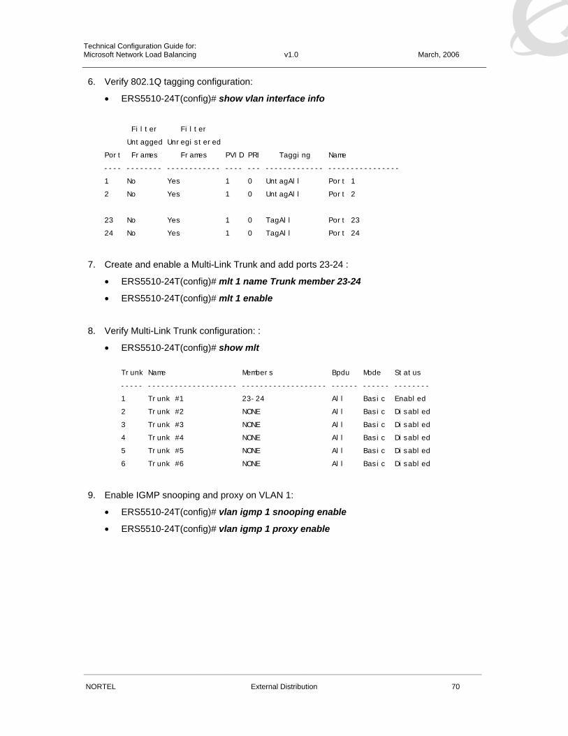
Technical Configuration Guide for: Microsoft Network Load Balancing v1.0 March, 2006
______________________________________________________________________________________________________
NORTEL External Distribution 70
6. Verify 802.1Q tagging configuration:
• ERS5510-24T(config)# show vlan interface info
Filter Filter
Untagged Unregistered
Port Frames Frames PVID PRI Tagging Name
---- -------- ------------ ---- --- ------------- ----------------
1 No Yes 1 0 UntagAll Port 1
2 No Yes 1 0 UntagAll Port 2
23 No Yes 1 0 TagAll Port 23
24 No Yes 1 0 TagAll Port 24
7. Create and enable a Multi-Link Trunk and add ports 23-24 :
• ERS5510-24T(config)# mlt 1 name Trunk member 23-24
• ERS5510-24T(config)# mlt 1 enable
8. Verify Multi-Link Trunk configuration: :
• ERS5510-24T(config)# show mlt Trunk Name Members Bpdu Mode Status
----- -------------------- ------------------- ------ ------ --------
1 Trunk #1 23-24 All Basic Enabled
2 Trunk #2 NONE All Basic Disabled
3 Trunk #3 NONE All Basic Disabled
4 Trunk #4 NONE All Basic Disabled
5 Trunk #5 NONE All Basic Disabled
6 Trunk #6 NONE All Basic Disabled
9. Enable IGMP snooping and proxy on VLAN 1:
• ERS5510-24T(config)# vlan igmp 1 snooping enable
• ERS5510-24T(config)# vlan igmp 1 proxy enable

Technical Configuration Guide for: Microsoft Network Load Balancing v1.0 March, 2006
______________________________________________________________________________________________________
NORTEL External Distribution 71
10. Verify IGMP snooping and proxy are enabled on VLAN 1:
• ERS5510-24T(config)# show vlan igmp 1
Snooping: Enabled
Proxy: Enabled
Robust Value: 2
Query Time: 125 seconds
IGMPv1 Static Router Ports: NONE
IGMPv2 Static Router Ports: NONE
11. Verify IGMP is suppressing the multicast flows to the server ports:
• ERS5510-24T(config)# show vlan multicast membership 1
Multicast Group Address Port
----------------------- ----
239.255.1.50 1
239.255.1.50 3

Technical Configuration Guide for: Microsoft Network Load Balancing v1.0 March, 2006
______________________________________________________________________________________________________
NORTEL External Distribution 72
3.7.3 ES 470-24T – Configuration For the first step we will configure an Ethernet Switch 470-24T as follows:
1. Configure a management IP address of 192.168.2.10/24 and default gateway 192.168.2.1
2. Enable Auto-PVID
3. Create VLAN 2 and assign is as the management VLAN
4. Assign ports 1 – 24 to VLAN 2
5. Enable 802.1Q tagging on ports 23 – 24
6. Create a Multi-Link Trunk with ports 23 – 24 to connect to the ERS 5530-24TFD
From the Ethernet Switch Main Menu, select “Command Line Interface” to access the Nortel CLI.
1. At the CLI prompt, enter the configuration mode:
• ES470-24T>enable
• ES470-24T# configure terminal
2. Create a IP address on the Ethernet Switch for management:
• ES470-24T(config)# ip address switch 192.168.2.10 netmask 255.255.255.0
3. Configure a default gateway:
• ES470-24T(config)# ip default-gateway 192.168.2.1
4. Verify IP addressing:
• ES470-24T(config)# show ip BootP Mode: BootP Disabled
Configured In Use Last BootP
--------------- --------------- ---------------
Stack IP Address: 0.0.0.0 0.0.0.0
Switch IP Address: 192.168.2.10 192.168.2.10 0.0.0.0
Subnet Mask: 255.255.255.0 255.255.255.0 0.0.0.0
Default Gateway: 192.168.2.1 192.168.2.1 0.0.0.0
5. Enable Auto-PVID:
• ES470-24T(config)# auto-pvid

Technical Configuration Guide for: Microsoft Network Load Balancing v1.0 March, 2006
______________________________________________________________________________________________________
NORTEL External Distribution 73
6. Verify Auto-PVID is enabled:
• ES470-24T(config)# show auto-pvid
AutoPVID: Enabled
7. Create port based VLAN with a id 2 and name it VLAN2:
• ES470-24T(config)# vlan create 2 name VLAN2 type port
8. Set the management VLAN to VLAN 2:
• ES470-24T(config)# vlan mgmt 2
9. Remove ports 1 – 24 from VLAN 1:
• ES470-24T(config)# vlan members remove 1 1-24
10. Add 1 – 24 to VLAN 2:
• ES470-24T(config)# vlan members add 2 1-24
11. Enable 802.1Q tagging on ports 23-24:
• ES470-24T(config)# vlan ports 23-24 tagging tagall
12. Verify VLAN configuration:
• ES470-24T(config)# vlan ports 23-24 tagging tagall Id Name Type Protocol User PID Active IVL/SVL Mgmt
--- -------------------- -------- ---------------- -------- ------ ------- ----
1 VLAN #1 Port None 0x0000 Yes IVL No
Port Members: NONE
2 VLAN2 Port None 0x0000 Yes IVL Yes
Port Members: 1-26
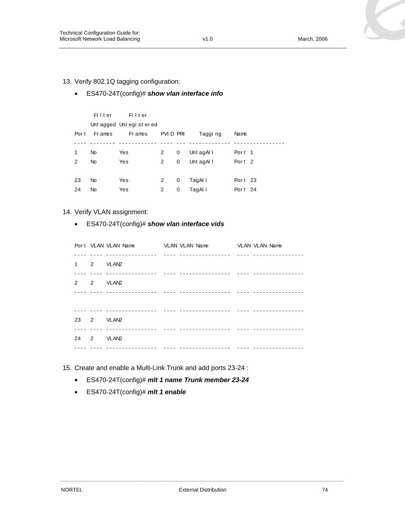
Technical Configuration Guide for: Microsoft Network Load Balancing v1.0 March, 2006
______________________________________________________________________________________________________
NORTEL External Distribution 74
13. Verify 802.1Q tagging configuration:
• ES470-24T(config)# show vlan interface info
Filter Filter
Untagged Unregistered
Port Frames Frames PVID PRI Tagging Name
---- -------- ------------ ---- --- ------------- ----------------
1 No Yes 2 0 UntagAll Port 1
2 No Yes 2 0 UntagAll Port 2
23 No Yes 2 0 TagAll Port 23
24 No Yes 2 0 TagAll Port 24
14. Verify VLAN assignment:
• ES470-24T(config)# show vlan interface vids
Port VLAN VLAN Name VLAN VLAN Name VLAN VLAN Name
---- ---- ---------------- ---- ---------------- ---- ----------------
1 2 VLAN2
---- ---- ---------------- ---- ---------------- ---- ----------------
2 2 VLAN2
---- ---- ---------------- ---- ---------------- ---- ----------------
---- ---- ---------------- ---- ---------------- ---- ----------------
23 2 VLAN2
---- ---- ---------------- ---- ---------------- ---- ----------------
24 2 VLAN2
---- ---- ---------------- ---- ---------------- ---- ----------------
15. Create and enable a Multi-Link Trunk and add ports 23-24 :
• ES470-24T(config)# mlt 1 name Trunk member 23-24
• ES470-24T(config)# mlt 1 enable

Technical Configuration Guide for: Microsoft Network Load Balancing v1.0 March, 2006
______________________________________________________________________________________________________
NORTEL External Distribution 75
16. Verify Multi-Link Trunk configuration: :
• ES470-24T(config)# show mlt Trunk Name Members Bpdu Mode Status
----- -------------------- ------------------- ------ ------ --------
1 Trunk #1 23-24 All Basic Enabled
2 Trunk #2 NONE All Basic Disabled
6 Trunk #6 NONE All Basic Disabled
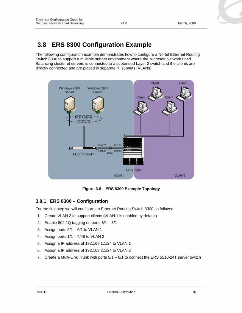
Technical Configuration Guide for: Microsoft Network Load Balancing v1.0 March, 2006
______________________________________________________________________________________________________
NORTEL External Distribution 76
3.8 ERS 8300 Configuration Example The following configuration example demonstrates how to configure a Nortel Ethernet Routing Switch 8300 to support a multiple subnet environment where the Microsoft Network Load Balancing cluster of servers is connected to a subtended Layer 2 switch and the clients are directly connected and are placed in separate IP subnets (VLANs).
Figure 3.8 – ERS 8300 Example Topology
3.8.1 ERS 8300 – Configuration For the first step we will configure an Ethernet Routing Switch 8300 as follows:
1. Create VLAN 2 to support clients (VLAN 1 is enabled by default)
2. Enable 802.1Q tagging on ports 5/1 – 6/1
3. Assign ports 5/1 – 6/1 to VLAN 1
4. Assign ports 1/1 – 4/48 to VLAN 2
5. Assign a IP address of 192.168.1.1/24 to VLAN 1
6. Assign a IP address of 192.168.2.1/24 to VLAN 2
7. Create a Multi-Link Trunk with ports 5/1 – 6/1 to connect the ERS 5510-24T server switch

Technical Configuration Guide for: Microsoft Network Load Balancing v1.0 March, 2006
______________________________________________________________________________________________________
NORTEL External Distribution 77
Connect to the Ethernet Routing Switch 8300 and log into the CLI with the username “rwa” and the password “rwa”.
1. Create port based VLAN with a id 2 and name it VLAN2:
• ERS8300# config vlan 2 create byport 1 name VLAN2
2. Remove ports 1/1 – 4/48 from VLAN 1:
ERS8300# config vlan 1 ports remove 1/1-4/48
3. Add ports 1/1 – 4/48 from VLAN 2:
ERS8300# config vlan 2 ports add 1/1-4/48
4. Enable 802.1Q tagging on ports 5/1 and 6/1:
• ERS8300# config ethernet 5/1-6/1 perform-tagging enable
5. Verify ports VLAN membership:
• ERS8300# show vlan info ports
================================================================================
Vlan Port
================================================================================
VLAN PORT ACTIVE STATIC NOT_ALLOW
ID MEMBER MEMBER MEMBER MEMBER
--------------------------------------------------------------------------------
1 5/1-6/8 5/1-6/8
2 1/1-4/48 1/1-4/48
6. Verify ports 5/1 – 6/1 tagging configuration:
• ERS8300# show ports info vlans vlan 1 port 5/1,6/1 ================================================================================
Port Vlans
================================================================================
PORT DISCARD DISCARD DEFAULT VLAN PORT UNTAG
NUM TAGGING TAGFRAM UNTAGFRAM VLANID IDS TYPE DEFVLAN
--------------------------------------------------------------------------------
5/1 enable false false 1 1 normal disable
6/1 enable false false 1 1 normal disable

Technical Configuration Guide for: Microsoft Network Load Balancing v1.0 March, 2006
______________________________________________________________________________________________________
NORTEL External Distribution 78
7. Create a IP address 192.168.1.1 and subnet mask 255.255.255.0 on VLAN 1:
• ERS8300# config vlan 1 ip create 192.168.1.1/24
8. Create a IP address 192.168.2.1 and subnet mask 255.255.255.0 on VLAN 2:
• ERS8300# config vlan 2 ip create 192.168.2.1/24
9. Verify IP Interface configuration:
• ERS8300# show vlan info ip
================================================================================
Vlan Ip
================================================================================
VLAN IP NET BCASTADDR REASM ADVERTISE DIRECTED
ID ADDRESS MASK FORMAT MAXSIZE WHEN_DOWN BROADCAST
--------------------------------------------------------------------------------
1 192.168.1.1 255.255.255.0 ones 1500 disable enable
2 192.168.2.1 255.255.255.0 ones 1500 disable enable
10. Create a Distributed Multi-Link Trunking group and add ports 5/1 – 6/1:
• ERS8300# mlt 1 create
• ERS8300# mlt 1 name DMLT_1
• ERS8300# mlt 1 perform-tagging en
• ERS8300# mlt 1 add ports 5/1,6/1
• ERS8300# mlt 1 add vlan 1
11. Verify Multi-Link Trunking configuration:
• ERS8300# show mlt info 1 ================================================================================
Mlt Info
================================================================================
PORT SVLAN MLT MLT PORT VLAN
MLTID IFINDEX NAME TYPE TYPE ADMIN CURRENT MEMBERS IDS
--------------------------------------------------------------------------------
1 4096 DMLT_1 trunk normal norm norm 5/1,6/1 1
MULTICAST DESIGNATED LACP LACP
MLTID IFINDEX DISTRIBUTION NT-STG PORTS ADMIN OPER
--------------------------------------------------------------------------------
1 4096 disable enable 2/1 disable down

Technical Configuration Guide for: Microsoft Network Load Balancing v1.0 March, 2006
______________________________________________________________________________________________________
NORTEL External Distribution 79
3.8.2 ERS 5510-24T – Configuration For the first step we will configure an Ethernet Routing Switch 5510-24T as follows:
1. Configure a management IP address of 192.168.1.10/24 and default gateway 192.168.1.1
2. Enable 802.1Q tagging on ports 23 – 24
3. Create a Multi-Link Trunk with ports 23 – 24 to connect to the ERS 8300
4. Enable IGMPv2 snooping and proxy to provide NLB multicast suppression
From the Ethernet Switch Main Menu, select “Command Line Interface” to access the Nortel CLI.
1. At the CLI prompt, enter the configuration mode:
• ERS5510-24T>enable
• ERS5510-24T# configure terminal
2. Create a IP address on the Ethernet Switch for management:
• ERS5510-24T(config)# ip address switch 192.168.1.10 netmask 255.255.255.0
3. Configure a default gateway:
• ERS5510-24T(config)# ip default-gateway 192.168.1.1
4. Verify IP addressing:
• ERS5510-24T(config)# show ip BootP Mode: BootP Disabled
Configured In Use Last BootP
--------------- --------------- ---------------
Stack IP Address: 0.0.0.0 0.0.0.0
Switch IP Address: 192.168.1.10 192.168.1.10 0.0.0.0
Subnet Mask: 255.255.255.0 255.255.255.0 0.0.0.0
Default Gateway: 192.168.1.1 192.168.1.1 0.0.0.0
5. Enable 802.1Q tagging on ports 23-24:
• ERS5510-24T(config)# vlan ports 23-24 tagging tagall

Technical Configuration Guide for: Microsoft Network Load Balancing v1.0 March, 2006
______________________________________________________________________________________________________
NORTEL External Distribution 80
6. Verify 802.1Q tagging configuration:
• ERS5510-24T(config)# show vlan interface info
Filter Filter
Untagged Unregistered
Port Frames Frames PVID PRI Tagging Name
---- -------- ------------ ---- --- ------------- ----------------
1 No Yes 1 0 UntagAll Port 1
2 No Yes 1 0 UntagAll Port 2
23 No Yes 1 0 TagAll Port 23
24 No Yes 1 0 TagAll Port 24
7. Create and enable a Multi-Link Trunk and add ports 23-24 :
• ERS5510-24T(config)# mlt 1 name Trunk member 23-24
• ERS5510-24T(config)# mlt 1 enable
8. Verify Multi-Link Trunk configuration: :
• ERS5510-24T(config)# show mlt Trunk Name Members Bpdu Mode Status
----- -------------------- ------------------- ------ ------ --------
1 Trunk #1 23-24 All Basic Enabled
2 Trunk #2 NONE All Basic Disabled
6 Trunk #6 NONE All Basic Disabled
9. Enable IGMP snooping and proxy on VLAN 1:
• ERS5510-24T(config)# vlan igmp 1 snooping enable
• ERS5510-24T(config)# vlan igmp 1 proxy enable
10. Verify IGMP snooping and proxy are enabled on VLAN 1:
• ERS5510-24T(config)# show vlan igmp 1
Snooping: Enabled
Proxy: Enabled
Robust Value: 2
Query Time: 125 seconds
IGMPv1 Static Router Ports: NONE
IGMPv2 Static Router Ports: NONE

Technical Configuration Guide for: Microsoft Network Load Balancing v1.0 March, 2006
______________________________________________________________________________________________________
NORTEL External Distribution 81
11. Verify IGMP is suppressing the multicast flows to the server ports:
• ERS5510-24T(config)# show vlan multicast membership 1
Multicast Group Address Port
----------------------- ----
239.255.1.50 1
239.255.1.50 3

Technical Configuration Guide for: Microsoft Network Load Balancing v1.0 March, 2006
______________________________________________________________________________________________________
NORTEL External Distribution 82
3.9 ERS 8600 Configuration Example 1 The following configuration example demonstrates how to configure a Nortel Ethernet Routing Switch 8600 to support a multiple subnet environment where the Microsoft Network Load Balancing cluster of servers is connected to a subtended Layer 2 switch and the clients are directly connected and are placed in separate IP subnets (VLANs).
3.9.1 ERS 8600 – Configuration For the first step we will configure an Ethernet Routing Switch 8600 as follows:
1. Create VLAN 2 to support clients (VLAN 1 is enabled by default)
2. Enable 802.1Q tagging on ports 4/1 – 7/1
3. Assign ports 4/1 – 7/1 to VLAN 1
4. Assign ports 1/1 – 3/48 to VLAN 2
5. Assign a IP address of 192.168.1.1/24 to VLAN 1
6. Assign a IP address of 192.168.2.1/24 to VLAN 2
7. Create a Multi-Link Trunk with ports 4/1 – 7/1 to connect the ERS 5510-24T server switch

Technical Configuration Guide for: Microsoft Network Load Balancing v1.0 March, 2006
______________________________________________________________________________________________________
NORTEL External Distribution 83
Connect to the Ethernet Routing Switch 8600 and log into the CLI with the username “rwa” and the password “rwa”.
1. Create port based VLAN with a id 2 and name it VLAN2:
• ERS8600# config vlan 2 create byport 1 name VLAN2
2. Remove ports 1/1 – 3/48 from VLAN 1:
ERS8600# config vlan 1 ports remove 1/1-3/48
3. Add ports 1/1 – 3/48 from VLAN 2:
ERS8600# config vlan 2 ports add 1/1-3/48
4. Enable 802.1Q tagging on ports 4/1 and 7/1:
• ERS8600# config ethernet 4/1-7/1 perform-tagging enable
5. Verify ports VLAN membership:
• ERS8600# show vlan info ports
================================================================================
Vlan Port
================================================================================
VLAN PORT ACTIVE STATIC NOT_ALLOW
ID MEMBER MEMBER MEMBER MEMBER
--------------------------------------------------------------------------------
1 4/1-4/8,7/1-7/8 4/1-4/8,7/1-7/8
2 1/1-3/48 1/1-3/48
6. Verify ports 4/1 – 7/1 tagging configuration:
• ERS8600# show ports info vlans vlan 1 port 4/1,7/1 ================================================================================
Port Vlans
================================================================================
PORT DISCARD DISCARD DEFAULT VLAN PORT UNTAG
NUM TAGGING TAGFRAM UNTAGFRAM VLANID IDS TYPE DEFVLAN
--------------------------------------------------------------------------------
5/1 enable false false 1 1 normal disable
6/1 enable false false 1 1 normal disable

Technical Configuration Guide for: Microsoft Network Load Balancing v1.0 March, 2006
______________________________________________________________________________________________________
NORTEL External Distribution 84
7. Create a IP address 192.168.1.1 and subnet mask 255.255.255.0 on VLAN 1:
• ERS8600# config vlan 1 ip create 192.168.1.1/24
8. Create a IP address 192.168.2.1 and subnet mask 255.255.255.0 on VLAN 2:
• ERS8600# config vlan 2 ip create 192.168.2.1/24
9. Verify IP Interface configuration:
• ERS8600# show vlan info ip
================================================================================
Vlan Ip
================================================================================
VLAN IP NET BCASTADDR REASM ADVERTISE DIRECTED
ID ADDRESS MASK FORMAT MAXSIZE WHEN_DOWN BROADCAST
--------------------------------------------------------------------------------
1 192.168.1.1 255.255.255.0 ones 1500 disable enable
2 192.168.2.1 255.255.255.0 ones 1500 disable enable
10. Create a Distributed Multi-Link Trunking group and add ports 5/1 – 6/1:
• ERS8600# mlt 1 create
• ERS8600# mlt 1 name DMLT_1
• ERS8600# mlt 1 perform-tagging en
• ERS8600# mlt 1 add ports 4/1,7/1
• ERS8600# mlt 1 add vlan 1
11. Verify Multi-Link Trunking configuration:
• ERS8600# show mlt info 1 ================================================================================
Mlt Info
================================================================================
PORT SVLAN MLT MLT PORT VLAN
MLTID IFINDEX NAME TYPE TYPE ADMIN CURRENT MEMBERS IDS
--------------------------------------------------------------------------------
1 4096 DMLT_1 trunk normal norm norm 4/1,7/1 1
MULTICAST DESIGNATED LACP LACP
MLTID IFINDEX DISTRIBUTION NT-STG PORTS ADMIN OPER
--------------------------------------------------------------------------------
1 4096 disable enable 2/1 disable down

Technical Configuration Guide for: Microsoft Network Load Balancing v1.0 March, 2006
______________________________________________________________________________________________________
NORTEL External Distribution 85
3.9.2 ERS 5510-24T – Configuration For the first step we will configure an Ethernet Routing Switch 5510-24T as follows:
1. Configure a management IP address of 192.168.1.10/24 and default gateway 192.168.1.1
2. Enable 802.1Q tagging on ports 23 – 24
3. Create a Multi-Link Trunk with ports 23 – 24 to connect to the ERS 8300
4. Enable IGMPv2 snooping and proxy to provide NLB multicast suppression
From the Ethernet Switch Main Menu, select “Command Line Interface” to access the Nortel CLI.
1. At the CLI prompt, enter the configuration mode:
• ERS5510-24T>enable
• ERS5510-24T# configure terminal
2. Create a IP address on the Ethernet Switch for management:
• ERS5510-24T(config)# ip address switch 192.168.1.10 netmask 255.255.255.0
3. Configure a default gateway:
• ERS5510-24T(config)# ip default-gateway 192.168.1.1
4. Verify IP addressing:
• ERS5510-24T(config)# show ip BootP Mode: BootP Disabled
Configured In Use Last BootP
--------------- --------------- ---------------
Stack IP Address: 0.0.0.0 0.0.0.0
Switch IP Address: 192.168.1.10 192.168.1.10 0.0.0.0
Subnet Mask: 255.255.255.0 255.255.255.0 0.0.0.0
Default Gateway: 192.168.1.1 192.168.1.1 0.0.0.0
5. Enable 802.1Q tagging on ports 23-24:
• ERS5510-24T(config)# vlan ports 23-24 tagging tagall

Technical Configuration Guide for: Microsoft Network Load Balancing v1.0 March, 2006
______________________________________________________________________________________________________
NORTEL External Distribution 86
6. Verify 802.1Q tagging configuration:
• ERS5510-24T(config)# show vlan interface info
Filter Filter
Untagged Unregistered
Port Frames Frames PVID PRI Tagging Name
---- -------- ------------ ---- --- ------------- ----------------
1 No Yes 1 0 UntagAll Port 1
2 No Yes 1 0 UntagAll Port 2
23 No Yes 1 0 TagAll Port 23
24 No Yes 1 0 TagAll Port 24
7. Create and enable a Multi-Link Trunk and add ports 23-24 :
• ERS5510-24T(config)# mlt 1 name Trunk member 23-24
• ERS5510-24T(config)# mlt 1 enable
8. Verify Multi-Link Trunk configuration: :
• ERS5510-24T(config)# show mlt Trunk Name Members Bpdu Mode Status
----- -------------------- ------------------- ------ ------ --------
1 Trunk #1 23-24 All Basic Enabled
2 Trunk #2 NONE All Basic Disabled
3 Trunk #3 NONE All Basic Disabled
6 Trunk #6 NONE All Basic Disabled
9. Enable IGMP snooping and proxy on VLAN 1:
• ERS5510-24T(config)# vlan igmp 1 snooping enable
• ERS5510-24T(config)# vlan igmp 1 proxy enable
10. Verify IGMP snooping and proxy are enabled on VLAN 1:
• ERS5510-24T(config)# show vlan igmp 1
Snooping: Enabled
Proxy: Enabled
Robust Value: 2
Query Time: 125 seconds
IGMPv1 Static Router Ports: NONE

Technical Configuration Guide for: Microsoft Network Load Balancing v1.0 March, 2006
______________________________________________________________________________________________________
NORTEL External Distribution 87
IGMPv2 Static Router Ports: NONE
11. Verify IGMP is suppressing the multicast flows to the server ports:
• ERS5510-24T(config)# show vlan multicast membership 1
Multicast Group Address Port
----------------------- ----
239.255.1.50 1
239.255.1.50 3

Technical Configuration Guide for: Microsoft Network Load Balancing v1.0 March, 2006
______________________________________________________________________________________________________
NORTEL External Distribution 88
3.10 ERS 8600 Configuration Example 2 The following configuration example demonstrates how to configure an Ethernet Routing Switch 8600 to support a multiple subnet environment where the Microsoft Network Load Balancing cluster of servers and clients are directly connected but are placed in separate IP subnets (VLANs).
For the first example we will demonstrate how to configure the Ethernet Routing Switch 8600 to support Network Load Balancing cluster of servers in unicast mode. For the second example we will demonstrate how to configure the Ethernet Routing Switch 8600 to support Network Load Balancing cluster of servers in multicast mode.
3.10.1 ERS 8600 – Configuration (Unicast Mode) For this example we will configure an Ethernet Routing Switch 8600 as follows:
1. Create VLAN 2 to support clients (VLAN 1 is enabled by default)
2. Enable 802.1Q tagging on ports 4/1 – 7/1
3. Assign ports 1/1 – 1/48 to VLAN 1
4. Assign ports 2/1 – 4/48 to VLAN 2
5. Enable the NLB unicast flooding feature on VLAN 1
6. Assign a IP address of 192.168.1.1/24 to VLAN 1
7. Assign a IP address of 192.168.2.1/24 to VLAN 2

Technical Configuration Guide for: Microsoft Network Load Balancing v1.0 March, 2006
______________________________________________________________________________________________________
NORTEL External Distribution 89
Connect to the Ethernet Routing Switch 8600 and log into the CLI with the username “rwa” and the password “rwa”.
1. Create port based VLAN with a id 2 and name it VLAN2:
• ERS8600# config vlan 2 create byport 1 name VLAN2
2. Remove ports 1/1 – 1/48 from VLAN 1:
ERS8600# config vlan 1 ports remove 1/1-1/48
3. Add ports 2/1 – 4/48 from VLAN 2:
ERS8600# config vlan 2 ports add 2/1-4/48
4. Verify ports VLAN membership:
• ERS8600# show vlan info ports
================================================================================
Vlan Port
================================================================================
VLAN PORT ACTIVE STATIC NOT_ALLOW
ID MEMBER MEMBER MEMBER MEMBER
--------------------------------------------------------------------------------
1 1/1-1/48 1/1-1/48
2 2/1-4/48 2/1-4/48
1. Enable the NLB unicast flooding feature on VLAN 1 so that unicast frames are flooded to all hosts in the Network Load Balancing cluster:
ERS8600# config vlan 1 ip nlb-unicast-mode enable
2. Verify that the NLB unicast flooding feature is enabled on VLAN 1:
ERS8600# config vlan 1 ip nlb-unicast-mode info
nlb-unicast-mode : enable
5. Create a IP address 192.168.1.1 and subnet mask 255.255.255.0 on VLAN 1:
• ERS8600# config vlan 1 ip create 192.168.1.1/24
6. Create a IP address 192.168.2.1 and subnet mask 255.255.255.0 on VLAN 2:
• ERS8600# config vlan 2 ip create 192.168.2.1/24

Technical Configuration Guide for: Microsoft Network Load Balancing v1.0 March, 2006
______________________________________________________________________________________________________
NORTEL External Distribution 90
7. Verify IP Interface configuration:
• ERS8600# show vlan info ip
================================================================================
Vlan Ip
================================================================================
VLAN IP NET BCASTADDR REASM ADVERTISE DIRECTED
ID ADDRESS MASK FORMAT MAXSIZE WHEN_DOWN BROADCAST
--------------------------------------------------------------------------------
1 192.168.1.1 255.255.255.0 ones 1500 disable enable
2 192.168.2.1 255.255.255.0 ones 1500 disable enable

Technical Configuration Guide for: Microsoft Network Load Balancing v1.0 March, 2006
______________________________________________________________________________________________________
NORTEL External Distribution 91
3.10.2 ERS 8600 – Configuration (Multicast Mode) For this example we will configure an Ethernet Routing Switch 8600 as follows:
1. Create VLAN 2 to support clients (VLAN 1 is enabled by default)
2. Assign ports 1/1 – 1/48 to VLAN 1
3. Assign ports 2/1 – 4/48 to VLAN 2
4. Enable the global multicast MAC flooding option
5. Assign a IP address of 192.168.1.1/24 to VLAN 1
6. Assign a IP address of 192.168.2.1/24 to VLAN 2
Connect to the Ethernet Routing Switch 8600 and log into the CLI with the username “rwa” and the password “rwa”.
1. Create port based VLAN with a id 2 and name it VLAN2:
• ERS8600# config vlan 2 create byport 1 name VLAN2
2. Remove ports 2/1 – 4/48 from VLAN 1:
ERS8600# config vlan 1 ports remove 1/1-1/48
3. Add ports 2/1 – 4/48 from VLAN 2:
ERS8600# config vlan 2 ports add 2/1-4/48
4. Verify ports VLAN membership:
• ERS8600# show vlan info ports
================================================================================
Vlan Port
================================================================================
VLAN PORT ACTIVE STATIC NOT_ALLOW
ID MEMBER MEMBER MEMBER MEMBER
--------------------------------------------------------------------------------
1 1/1-1/48 1/1-1/48
2 2/1-4/48 2/1-4/48
5. Enable the global multicast MAC flooding feature so that multicast frames are flooded to all hosts in the Network Load Balancing cluster:
ERS8600# config ip arp multicast-mac-flooding enable

Technical Configuration Guide for: Microsoft Network Load Balancing v1.0 March, 2006
______________________________________________________________________________________________________
NORTEL External Distribution 92
6. Verify that the multicast MAC flooding feature is enabled:
ERS8600# config ip arp info
Sub-Context: static-mcastmac
Current Context:
multicast-mac-flooding : enable
aging : 360 (min)
arpreqthreshold : 500
delete : N/A
add :
7. Create a IP address 192.168.1.1 and subnet mask 255.255.255.0 on VLAN 1:
• ERS8600# config vlan 1 ip create 192.168.1.1/24
8. Create a IP address 192.168.2.1 and subnet mask 255.255.255.0 on VLAN 2:
• ERS8600# config vlan 2 ip create 192.168.2.1/24
9. Verify IP Interface configuration:
• ERS8600# show vlan info ip
================================================================================
Vlan Ip
================================================================================
VLAN IP NET BCASTADDR REASM ADVERTISE DIRECTED
ID ADDRESS MASK FORMAT MAXSIZE WHEN_DOWN BROADCAST
--------------------------------------------------------------------------------
1 192.168.1.1 255.255.255.0 ones 1500 disable enable
2 192.168.2.1 255.255.255.0 ones 1500 disable enable

Technical Configuration Guide for: Microsoft Network Load Balancing v1.0 March, 2006
______________________________________________________________________________________________________
NORTEL External Distribution 93
4. Appendix A. NLB Port Rules Options
The following is a detailed overview of all the Port Rule options available in the “Add/Edit Port Rule” window that can be applied to hosts in a cluster. Parameter Description
Cluster IP Address Specifies options regarding which cluster IP addresses that the port rule should cover.
All Specifies whether the port rule is a global port rule and will cover all cluster IP addresses associated with the particular Network Load Balancing cluster.
Port Range Specifies the start and end of the port range for the selected port rule. Port numbers in a range of 0 to 65,535 are currently supported. The default port range is 0 to 65,535.
Protocols
Specifies the IP protocol that a port rule should cover: Transmission Control Protocol (TCP), User Datagram Protocol (UDP), or both. Only the network traffic for the specified protocol is affected by the rule. The default host will handle all traffic not covered by a port rule.
Multiple Host Specifies whether multiple hosts in the cluster handle network traffic for the associated port rule.
Affinity: None
Specifies whether multiple connections from the same client IP address can be handled by different hosts. Disabling affinity allows for more effective load balancing because it allows multiple connections from the same client to be handled concurrently by different cluster hosts. To maximize scaled performance when client affinity is not needed, disable affinity by selecting None. However, in order to allow Network Load Balancing to properly handle IP fragments, you should avoid using None when selecting UDP or Both for your protocol setting.
Affinity: Single
Specifies that Network Load Balancing direct multiple requests - Transmission Control Protocol (TCP) connections or User Datagram Protocol (UDP) datagram’s - from the same client Internet Protocol (IP) address to the same cluster host. This is the default setting for affinity. Using Single affinity ensures that only one cluster host will handle all connections that are part of the same client session. This is important if the server program running on the cluster host maintains session state (such as "server cookies") between connections.
Affinity: Class C
Specifies that Network Load Balancing direct multiple requests - Transmission Control Protocol (TCP) connections or User Datagram Protocol (UDP) datagram’s - from the same TCP/IP Class C address range to the same cluster host.
Affinity: Single Host
Specifies that network traffic for the associated port rule be handled by a single host in the cluster according to the specified handling priority. This filtering mode provides port specific fault tolerance for the handling of network traffic.
Disable this Port Range
Specifies whether all network traffic for the associated port rule will be blocked.

Technical Configuration Guide for: Microsoft Network Load Balancing v1.0 March, 2006
______________________________________________________________________________________________________
NORTEL External Distribution 94
B. Resources & Reference Documents Microsoft Resources
URL Description
http://www.microsoft.com/technet/prodtechnol/windowsserver2003/technologies/nlb.mspx
Windows Server 2003 Network Load Balancing (NLB) - Technical Library
http://support.microsoft.com/default.aspx?scid=kb;en-us;815752
Configure Windows XP or Windows Server 2003 for IGMP Version 1 or Version 2 Support
Contact Us:
For product support and sales information, visit the Nortel Networks website at:
http://www.nortel.com
In North America, dial toll-free 1-800-4Nortel, outside North America dial 987-288-3700.