TECHNICAL CATALOGUE - SGI Architectural · contained within this technical catalogue, without...
41
TECHNICAL CATALOGUE EXTERIORS Prodema NATURAL WOOD BEAUTY
Transcript of TECHNICAL CATALOGUE - SGI Architectural · contained within this technical catalogue, without...

TECHNICALCATALOGUE
EXTERIORS
ProdemaNATURAL WOOD BEAUTY
For the satisfactory installation of ProdEX panels, it is necessary to follow all the instructions contained within this technical catalogue, without exception.
For technical queries, alternative installation systems, etc., we recommend contacting Prodema ([email protected]).
The updated version of this present guide can be found on the Prodema website.
EDITION Nº 2
SPECIFIC CATALOGUE FOR
05/2015
EUROPEASIA
AFRICAOCEANIA
CENTRAL AND SOUTH AMERICA
4 5
CONTENTS
1. INTRODUCTION 1.1 CONSTRUCTION KIT CERTIFICATES .............................................................. 9 1.2 ENVIRONMENTAL COMMITMENT .................................................................. 10 1.3 TECHNICAL DATA SHEETS ..............................................................................11
2. PRIOR TO INSTALLATION OF THE PRODUCT 2.1 RECEIPT OF MATERIAL .................................................................................. 14 2.2 HANDLING AND STORAGE ............................................................................ 14 2.3 RANDOM POSITIONING OF PANELS ............................................................. 15 2.4 FABRICATION ................................................................................................... 16 2.4.1 CUTTING RECOMMENDATIONS ......................................................... 16 2.4.2 DRILLING RECOMMENDATIONS ......................................................... 17
3. INSTALLATION OF THE PRODUCT 3.1 GENERAL CONCEPTS .................................................................................... 18 3.1.1 VENTILATED FAÇADES ........................................................................ 18 3.1.2 EXPANSION JOINTS ............................................................................ 20 3.1.3 DIMENSIONAL STABILITY ................................................................... 21 3.1.4 SUBFRAMING OPTIONS ...................................................................... 22 3.1.5 MINIMUM SUPPORT POINTS PER PANEL .......................................... 24 3.1.6 TONGUE AND GROOVE AND COUNTERSUNK SCREWS ................. 25 3.2 INSTALLATION SYSTEM ................................................................................. 26 3.2.1 VISIBLE FASTENING WITH SCREWS OR RIVETS: FAÇADE ............. 26 3.2.2 CONCEALED FASTENING WITH CAPS ............................................... 32 3.2.3 CONCEALED FASTENING WITH HANGING HOOKS .......................... 34 3.2.4 CONCEALED FASTENING WITH ADHESIVE ....................................... 37 3.2.5 FIXED LOUVER SYSTEM ...................................................................... 40 3.2.6 CLAPBOARD SYSTEM .......................................................................... 46 3.3 UNIQUE FACADES ........................................................................................... 49 3.3.1 UNIQUE SHAPES ................................................................................. 49 3.3.2 SUSPENDED CEILINGS ....................................................................... 52 3.3.3 OPERABLE LOUVERS .......................................................................... 54 3.3.4 CURVED SURFACES ............................................................................ 55 3.4 INSTALLATION DETAILS .................................................................................. 65
4. POST-INSTALLATION 4.1 REMOVING THE PROTECTIVE SURFACE ..................................................... 66 4.2 CLEANING ........................................................................................................ 66 4.3 MAINTENANCE ................................................................................................ 67 4.4 REPAIR ............................................................................................................. 67
5. REMOVAL INFORMATION 5.1 REMOVAL ......................................................................................................... 67 5.2 WASTE MANAGEMENT ................................................................................... 67
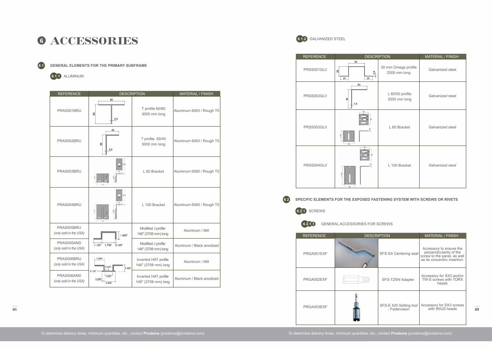
6. ACCESSORIES 6.1 GENERAL ELEMENTS FOR THE PRIMARY SUBFRAME .............................. 68 6.1.1 ALUMINUM ............................................................................................. 68 6.1.2 GALVANIZED STEEL ............................................................................. 69 6.2 SPECIFIC ELEMENTS FOR THE EXPOSED FASTENING SYSTEM WITH SCREWS OR RIVET .............................................................................. 69 6.2.1 SCREWS ................................................................................................ 69 6.2.2 RIVETS ................................................................................................... 72 6.3 SPECIFIC ELEMENTS FOR THE CONCEALED FASTENING WITH CAPS SYSTEM ...................................................................................... 75 6.3.1 GENERAL ACCESSORIES FOR THE CONCEALED FASTENING WITHCAP SYSTEM .......................................................... 75 6.3.2 CAPS ...................................................................................................... 75 6.4 SPECIFIC ELEMENTS FOR THE CONCEALED FASTENING SYSTEM WITH HANGING PROFILES ............................................................................ 76 6.4.1 GENERAL ACCESSORIES FOR THE CONCEALED SYSTEM ............ 76 6.5 SPECIFIC ELEMENTS FOR THE FIXED LOUVER SYSTEM ........................................................................................................... 76 6.5.1 GENERAL ACCESSORIES FOR THE FIXED LOUVER SYSTEM ................................................................................. 76 6.6 SPECIFIC ELEMENTS FOR THE CLAPBOARD SYSTEM .............................. 79 6.6.1 GENERAL ACCESSORIES FOR THE CLAPBOARD SYSTEM ............ 79
6 7
ProdEX. EXTERIORS
ProdEX is a construction kit for the cladding of ventilated façades made up of natural wood panels and the corresponding substructure. Each panel consists of a high density bakelite core, clad in a veneer of natural wood with a surface treated with synthetic resin and an exterior PVDF film, which lends greater durability to the panels, with anti-adherent properties, to protect the panel from solar radiation, atmospheric agents, dirt and the attacks of chemical products (anti-graffiti). Due to its high resistance, it does not require the typical maintenance of other woods for exteriors.
ProdEX panels are unique, no two are alike, each grain is different, which explains the difference in tone between them and which gives it a natural and authentic appearance that can be appreciated in the reflection of the light on its wood fibers.
At Prodema, we have invested a large part of our resources in constantly improving the quality of our products, subsequently obtaining different certificates of trials performed at independent laboratories.
This is because our philosophy of continual improvement obliges us to obtain the most demanding quality certificates, such as the ISO 9001 quality management standard.
1 INTRODUCTION
8 9
Panel thickness:, 18
Weight / unit surface area:, , 20, 22 mm
(mm)
(Kg/m2)
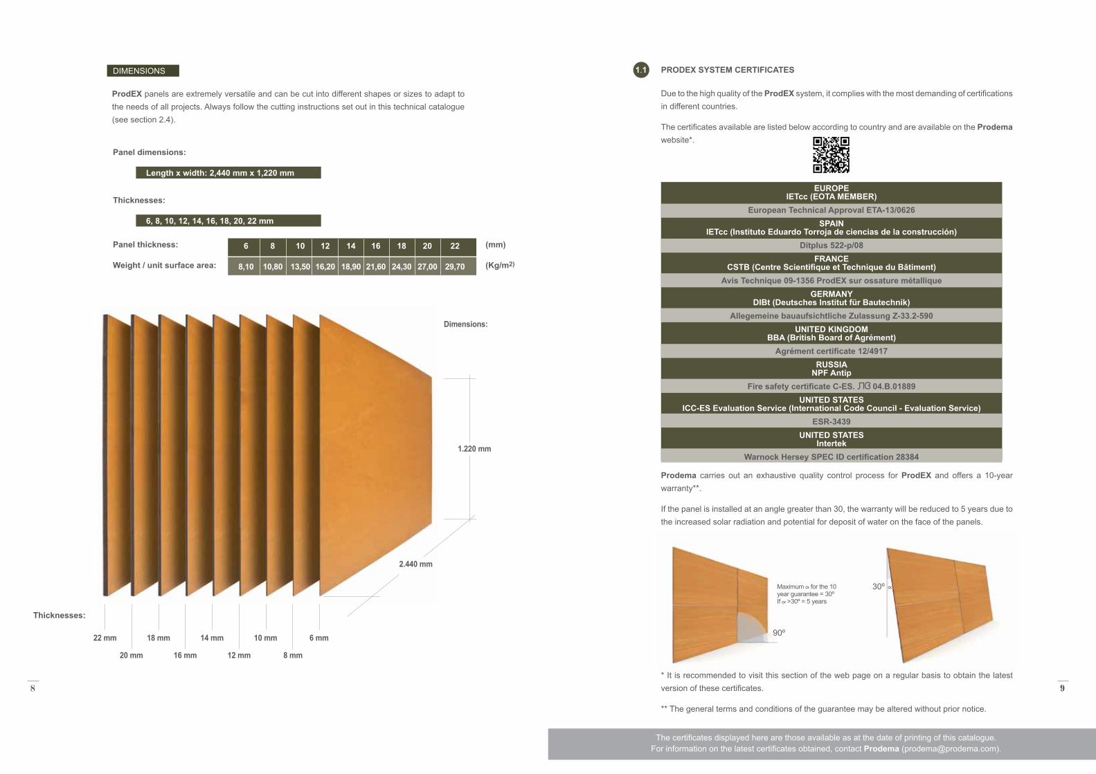
DIMENSIONS
Thicknesses:
ProdEX panels are extremely versatile and can be cut into different shapes or sizes to adapt to the needs of all projects. Always follow the cutting instructions set out in this technical catalogue (see section 2.4).
Dimensions:
1.220 mm
2.440 mm
22 mm 18 mm 14 mm 10 mm 6 mm
20 mm 16 mm 12 mm 8 mm
Panel dimensions:
Length x width: 2,440 mm x 1,220 mm
Thicknesses:
6, 8, 10, 12, 14, 16, 18, 20, 22 mm
PRODEX SYSTEM CERTIFICATES1 1
Due to the high quality of the ProdEX system, it complies with the most demanding of certifications in different countries.
The certificates available are listed below according to country and are available on the Prodema website*.
Prodema carries out an exhaustive quality control process for ProdEX and offers a 10-year warranty**.
If the panel is installed at an angle greater than 30, the warranty will be reduced to 5 years due to the increased solar radiation and potential for deposit of water on the face of the panels.
* It is recommended to visit this section of the web page on a regular basis to obtain the latest version of these certificates.
** The general terms and conditions of the guarantee may be altered without prior notice.
90º
30º
6 8 10 12 14 16 18 20 22
8,10 10,80 13,50 16,20 18,90 21,60 24,30 27,00 29,70
The certificates displayed here are those available as at the date of printing of this catalogue. For information on the latest certificates obtained, contact Prodema ([email protected]).
Maximum for the 10 year guarantee = 30º If >30º = 5 years
EUROPE IETcc (EOTA MEMBER)
European Technical Approval ETA-13/0626SPAIN
IETcc (Instituto Eduardo Torroja de ciencias de la construcción)Ditplus 522-p/08
FRANCE CSTB (Centre Scientifique et Technique du Bâtiment)
Avis Technique 09-1356 ProdEX sur ossature métalliqueGERMANY
DIBt (Deutsches Institut für Bautechnik)Allegemeine bauaufsichtliche Zulassung Z-33.2-590
UNITED KINGDOM BBA (British Board of Agrément)
Agrément certificate 12/4917RUSSIA
NPF AntipFire safety certificate C-ES. 04.B.01889
UNITED STATES ICC-ES Evaluation Service (International Code Council - Evaluation Service)
ESR-3439UNITED STATES
IntertekWarnock Hersey SPEC ID certification 28384
10 11
Prodema has had a long-standing commitment to the conservation of the environment and so we continually strive to develop initiatives to keep us at the forefront of sustainable practices.We have stayed true to this commitment and continue to contribute to our clients' environmental responsibilities and that of society in general.
In 2002, the ISO 14001 Environmental Management certification was granted to our factory in Legorreta (Spain), requiring that Prodema follow an environmental plan and improve its protocol as new industry and environmental standards develop.
More recently, we became the first company in our sector, world-wide,to obtain the ISO14006 for ECOdesign. ECOdesign recognizes companies for integrating environmental considerations into the design and development of products so as to reduce negative environmental impacts and continually improve the environmental performance of a product or service throughout its lilecycle. Prodema has also been granted the ECOlabel, recognizing the product's environmental impact during its lifecycle.
Prodema is PEFC certified which recognizes that we only use woods originating from managed forests that abide by the strictest environmental and socially responsible standards.
Prodema meets LEEDS standards and can contribute significant points to qualify for LEED certified buildings. Our products also meet the standards of other rating systems used throughout theworld (Breeam, Casbee, GBTool,and Green Globes)
ENVIRONMENTAL COMMITMENT
SUMMARY OF CERTIFICATES
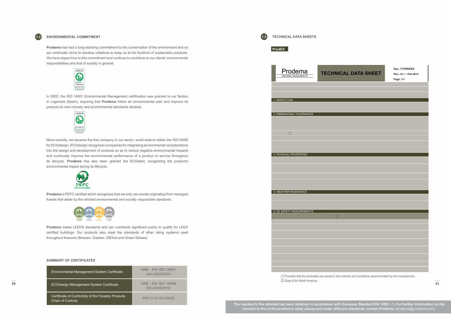
1 2 TECHNICAL DATA SHEETS1 3
ProdEX
TECHNICAL DATA SHEET
1. INSPECTION
2. DIMENSIONAL TOLERANCES
3. PHYSICAL PROPERTIES
4. WEATHER RESISTANCE
5. CE SAFETY REQUIREMENTS
Environmental Management System Certificate
ECOdesign Management System Certificate
Certificate of Conformity of the Forestry Products Chain of Custody
UNE - EN ISO 14001 GA-2002/0070
UNE - EN ISO 14006 ED-0009/2010
PEFC/14-35-00025
The reaction to fire detailed has been obtained in accordance with European Standard EN 13501 - 1. For further information on the reaction to fire of the product in other places and under different standards, contact Prodema ([email protected]).
ProdemaNATURAL WOOD BEAUTY
ProdemaNATURAL WOOD BEAUTY
ProdemaNATURAL WOOD BEAUTY
Provided that the laminates are stored in the manner and conditions recommended by the manufacturer. Class B for North America.2 1
2
1
12 13
ProdEX IGN ProdEX FIREPROOF
TECHNICAL DATA SHEET TECHNICAL DATA SHEET
ProdemaNATURAL WOOD BEAUTY
ProdemaNATURAL WOOD BEAUTY
ProdemaNATURAL WOOD BEAUTY
ProdemaNATURAL WOOD BEAUTY
ProdemaNATURAL WOOD BEAUTY
ProdemaNATURAL WOOD BEAUTY
1. INSPECTION 1. INSPECTION
2. DIMENSIONAL TOLERANCES 2. DIMENSIONAL TOLERANCES
3. PHYSICAL PROPERTIES 3. PHYSICAL PROPERTIES
4. WEATHER RESISTANCE 4. WEATHER RESISTANCE
5. CE SAFETY REQUIREMENTS 5. CE SAFETY REQUIREMENTS
The reaction to fire detailed has been obtained in accordance with European Standard EN 13501 - 1. For further information on the reaction to fire of the product in other places and under different standards, contact Prodema ([email protected]).
2
Provided that the laminates are stored in the manner and conditions recommended by the manufacturer. Class A for North America.
Provided that the laminates are stored in the manner and conditions recommended by the manufacturer.2 1 1
1 1
14 15
2 PRIOR TO INSTALLATION OF THE PRODUCT
RECEIPT OF MATERIAL
HANDLING AND STORAGE
2 1
2 2
Verify condition of package:
• In the case of visible damage, leave details on the transporter's delivery note.
• In the case of hidden damage, notify within 72 hours.
No claims will be accepted for transport damage if any of these instructions are not followed.
• ProdEX panels must be stored in a closed and climate controlled area, at an ambient temperature of 10–25º C and with an air humidity of 30–70%.
• It is recommended to store ProdEX panels in their original packaging until the time of installation. In the case of having to repackage any panel, this should be done under the same conditions as the original packaging.
• Once the packaging has been opened, it is recommended to remove only those ProdEX panels that will be installed immediately. The remaining panels must then be stored under the same conditions in the original packaging.
• ProdEX panels cannot be stored vertically, only in a horizontal position on a pallet with supports < 800mm in distance. Improper storage can result in warping of panels.
• The floor supporting the pallet must be free of material and debris that may affect the stability of the pallet.
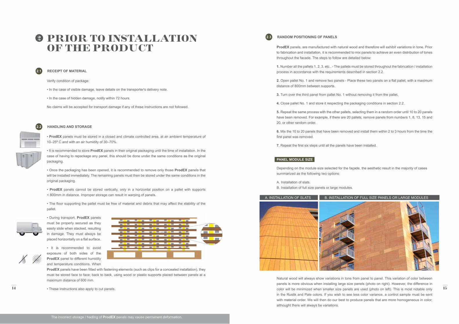
• During transport, ProdEX panels must be properly secured as they easily slide when stacked, resulting in damage. They must always be placed horizontally on a flat surface.
• It is recommended to avoid exposure of both sides of the ProdEX panel to different humidity and temperature conditions. When ProdEX panels have been fitted with fastening elements (such as clips for a concealed installation), they must be stored face to face; back to back, using wood or plastic supports placed between panels at a maximum distance of 600 mm.
• These instructions also apply to cut panels.
The incorrect storage / hadling of ProdEX panels may cause permanent deformation.
ProdEX panels, are manufactured with natural wood and therefore will exhibit variations in tone. Prior to fabrication and installation, it is recommended to mix panels to achieve an even distribution of tones throughout the facade. The steps to follow are detailed below:
1. Number all the pallets 1, 2, 3, etc., - The pallets must be stored throughout the fabrication / installation process in accordance with the requirements described in section 2.2.
2. Open pallet No. 1 and remove two panels - Place these two panels on a flat pallet, with a maximum distance of 800mm between supports.
3. Turn over the third panel from pallet No. 1 without removing it from the pallet.
4. Close pallet No. 1 and store it respecting the packaging conditions in section 2.2.
5. Repeat the same process with the other pallets, selecting them in a random order until 10 to 20 panels have been removed. For example, if there are 20 pallets, remove panels from numbers 1, 8, 13, 15 and 20, or other random order.
6. Mix the 10 to 20 panels that have been removed and install them within 2 to 3 hours from the time the first panel was removed.
7. Repeat the first six steps until all the panels have been installed.
PANEL MODULE SIZE
Depending on the module size selected for the façade, the aesthetic result in the majority of cases summarized as the following two options:
A. Installation of slats. B. Installation of full size panels or large modules.
Natural wood will always show variations in tone from panel to panel. This variation of color between panels is more obvious when installing large size panels (photo on right). However, the difference in color will be minimized when smaller size panels are used (photo on left). This is most notable only in the Rustik and Pale colors. If you wish to see less color variance, a control sample must be sent with material order. We will then do our best to produce panels that are more homogeneous in color, althought there will always be variations.
RANDOM POSITIONING OF PANELS2 3
A. INSTALLATION OF SLATS B. INSTALLATION OF FULL SIZE PANELS OR LARGE MODULES
16 17
C. ALTERNATIVE SYSTEMS
Apart from the already mentioned systems, there are other machining options but not all of them are compatible with the material.
• Waterjet cutting: this system is compatible with the ProdEX panels, however, it is advisable to carry out a test beforehand to adjust the parameters.
• Laser cutting: this system is not recommended for use on ProdEX panels as they blacken and burn the wood veneer.
Drilling Speeds Recommendations:
• Cutting speed: 16,000 rpm. • Feed speed: 4 m / min.
NOTE: Only use as reference as these will vary according to each tool.
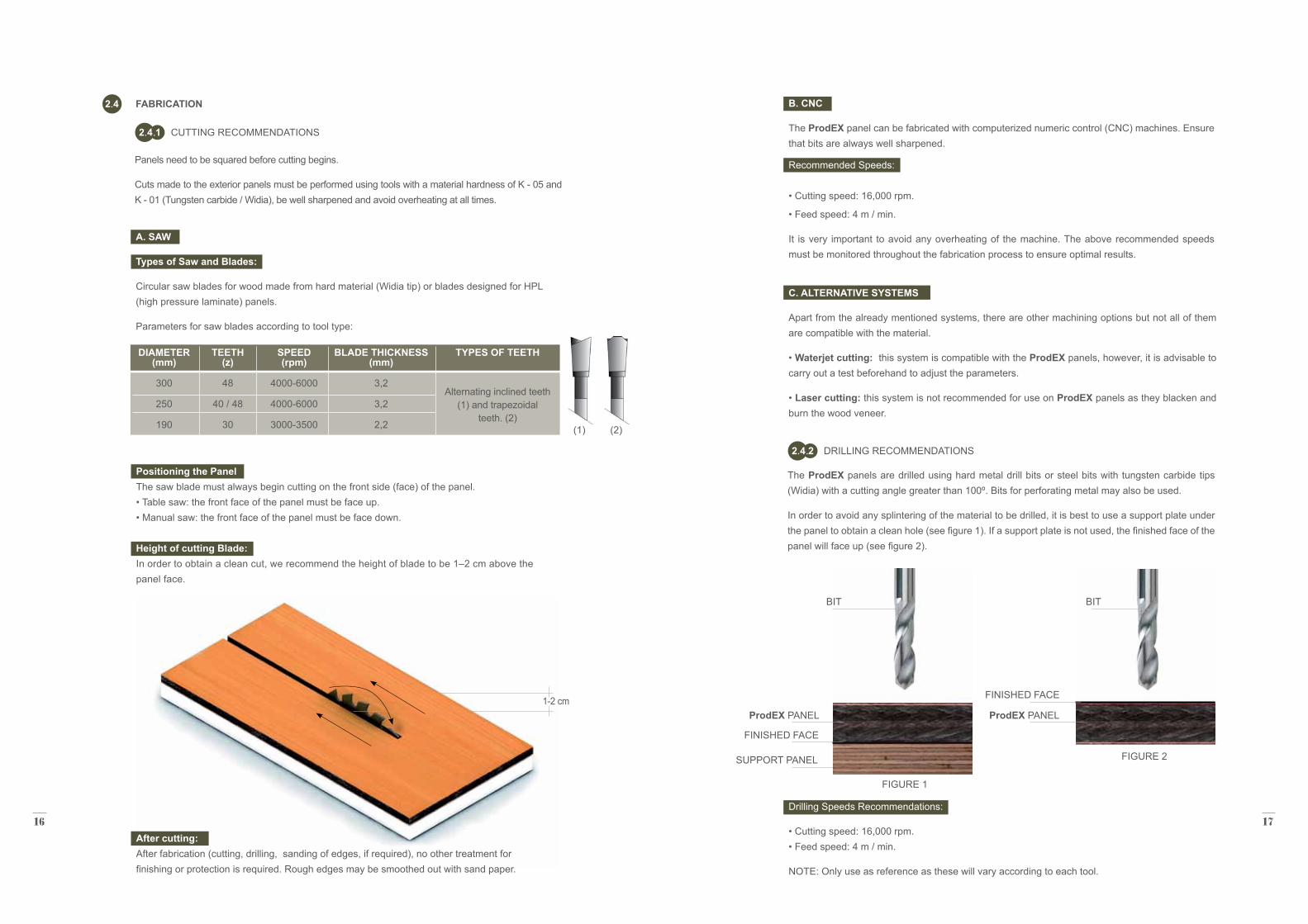
The ProdEX panels are drilled using hard metal drill bits or steel bits with tungsten carbide tips (Widia) with a cutting angle greater than 100º. Bits for perforating metal may also be used.
In order to avoid any splintering of the material to be drilled, it is best to use a support plate under the panel to obtain a clean hole (see figure 1). If a support plate is not used, the finished face of the panel will face up (see figure 2).
DRILLING RECOMMENDATIONS2 4 2
BIT BIT
ProdEX PANEL ProdEX PANEL
SUPPORT PANEL FIGURE 2
FIGURE 1
FINISHED FACE
FINISHED FACE
A. SAW
Types of Saw and Blades:
Circular saw blades for wood made from hard material (Widia tip) or blades designed for HPL (high pressure laminate) panels.
Parameters for saw blades according to tool type:
SPEED (rpm)
4000-6000
4000-6000
3000-3500
BLADE THICKNESS (mm)
3,2
3,2
2,2
TYPES OF TEETH
Alternating inclined teeth (1) and trapezoidal
teeth. (2)
TEETH (z)
48
40 / 48
30 (1) (2)
FABRICATION2 4
Panels need to be squared before cutting begins.
Cuts made to the exterior panels must be performed using tools with a material hardness of K - 05 and K - 01 (Tungsten carbide / Widia), be well sharpened and avoid overheating at all times.
CUTTING RECOMMENDATIONS2 4 1
DIAMETER (mm)
300
250
190
Positioning the Panel The saw blade must always begin cutting on the front side (face) of the panel. • Table saw: the front face of the panel must be face up. • Manual saw: the front face of the panel must be face down. Height of cutting Blade: In order to obtain a clean cut, we recommend the height of blade to be 1–2 cm above the panel face.
After cutting: After fabrication (cutting, drilling, sanding of edges, if required), no other treatment for finishing or protection is required. Rough edges may be smoothed out with sand paper.
1-2 cm
B. CNC
The ProdEX panel can be fabricated with computerized numeric control (CNC) machines. Ensure that bits are always well sharpened.
Recommended Speeds: • Cutting speed: 16,000 rpm.
• Feed speed: 4 m / min.
It is very important to avoid any overheating of the machine. The above recommended speeds must be monitored throughout the fabrication process to ensure optimal results.
18 19
3
GENERAL CONCEPTS3 1
INSTALLATION OF THE PRODUCT
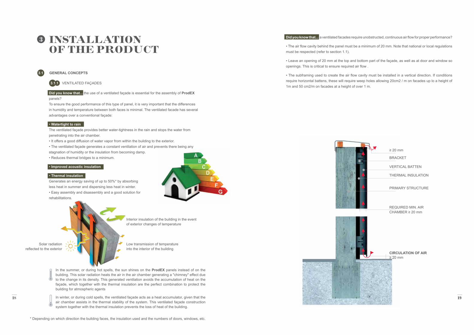
Did you know that... the use of a ventilated façade is essential for the assembly of ProdEX panels? To ensure the good performance of this type of panel, it is very important that the differences in humidity and temperature between both faces is minimal. The ventilated facade has several advantages over a conventional façade:
• Watertight to rain The ventilated façade provides better water-tightness in the rain and stops the water from penetrating into the air chamber. • It offers a good diffusion of water vapor from within the building to the exterior. • The ventilated façade generates a constant ventilation of air and prevents there being any stagnation of humidity or the insulation from becoming damp. • Reduces thermal bridges to a minimum.
• Improved acoustic insulation
• Thermal insulation Generates an energy saving of up to 50%* by absorbing less heat in summer and dispersing less heat in winter. • Easy assembly and disassembly and a good solution for rehabilitations.
Did you know that... a ventilated facades require unobstructed, continuous air flow for proper performance?
• The air flow cavity behind the panel must be a minimum of 20 mm. Note that national or local regulations must be respected (refer to section 1.1).
• Leave an opening of 20 mm at the top and bottom part of the façade, as well as at door and window so openings. This is critical to ensure required air flow .
• The subframing used to create the air flow cavity must be installed in a vertical direction. If conditions require horizontal battens, these will require weep holes allowing 20cm2 / m on facades up lo a height of 1m and 50 cm2/m on facades at a height of over 1 m.
BRACKET
VERTICAL BATTEN
THERMAL INSULATION
PRIMARY STRUCTURE
CIRCULATION OF AIR
REQUIRED MIN. AIR CHAMBER ≥ 20 mm
≥ 20 mm
≥ 20 mm
VENTILATED FAÇADES3 1 1
* Depending on which direction the building faces, the insulation used and the numbers of doors, windows, etc.
Low transmission of temperature into the interior of the building
Solar radiation reflected to the exterior
In the summer, or during hot spells, the sun shines on the ProdEX panels instead of on the building. This solar radiation heats the air in the air chamber generating a "chimney" effect due to the change in its density. This generated ventilation avoids the accumulation of heat on the façade, which together with the thermal insulation are the perfect combination to protect the building for atmospheric agents
In winter, or during cold spells, the ventilated façade acts as a heat accumulator, given that the air chamber assists in the thermal stability of the system. This ventilated façade construction system together with the thermal insulation prevents the loss of heat of the building.
Interior insulation of the building in the event of exterior changes of temperature
20 21
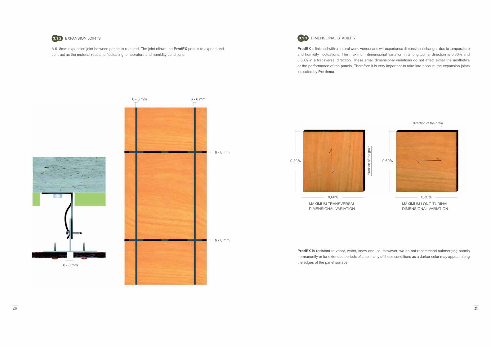
A 6–8mm expansion joint between panels is required. The joint allows the ProdEX panels to expand and contract as the material reacts to fluctuating temperature and humidity conditions.
EXPANSION JOINTS3 1 2
6 - 8 mm
6 - 8 mm6 - 8 mm
6 - 8 mm
6 - 8 mm
DIMENSIONAL STABILITY
ProdEX is finished with a natural wood veneer and will experience dimensional changes due to temperature and humidity fluctuations. The maximum dimensional variation in a longitudinal direction is 0.30% and 0.60% in a transversal direction. These small dimensional variations do not affect either the aesthetics or the performance of the panels. Therefore it is very important to take into account the expansion joints indicated by Prodema.
ProdEX is resistant to vapor, water, snow and ice. However, we do not recommend submerging panels permanently or for extended periods of time in any of these conditions as a darker color may appear along the edges of the panel surface.
3 1 3
0,60%
0,30% 0,60%
direction of the grain
0,30%
MAXIMUM TRANSVERSAL DIMENSIONAL VARIATION
MAXIMUM LONGITUDINAL DIMENSIONAL VARIATION
22 23
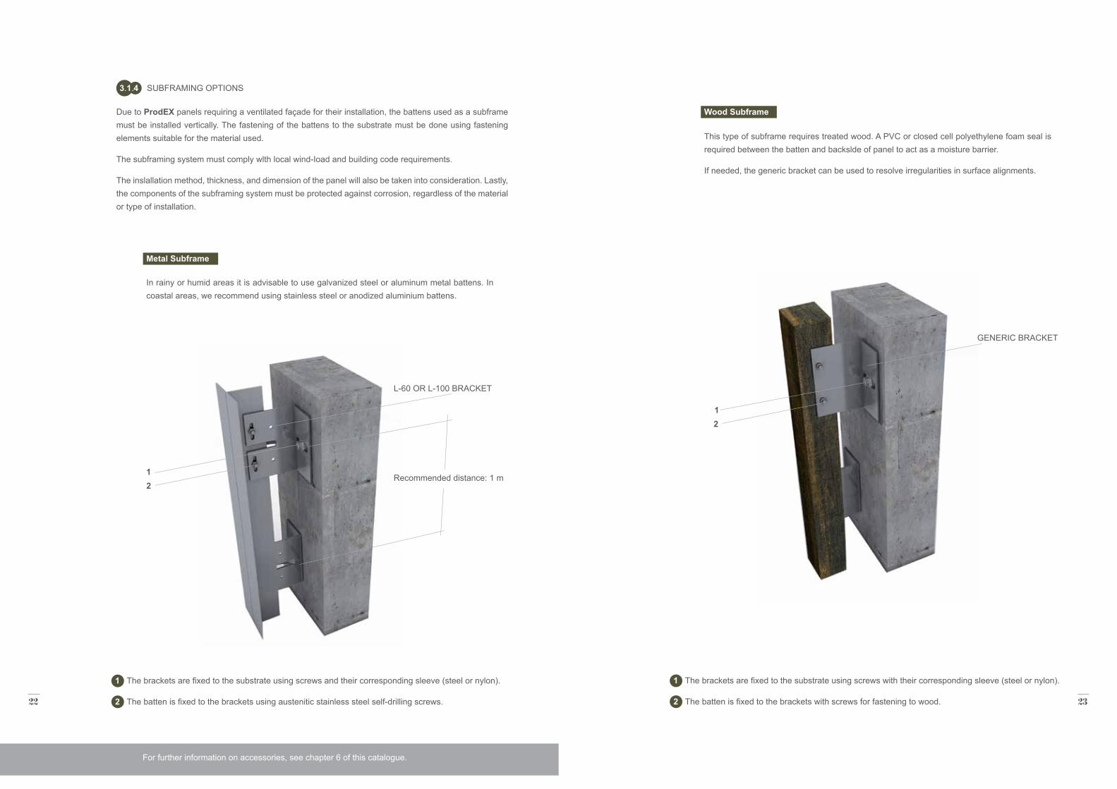
Due to ProdEX panels requiring a ventilated façade for their installation, the battens used as a subframe must be installed vertically. The fastening of the battens to the substrate must be done using fastening elements suitable for the material used.
The subframing system must comply wlth local wind-Ioad and building code requirements.
The inslallation method, thickness, and dimension of the panel will also be taken into consideration. Lastly, the components of the subframing system must be protected against corrosion, regardless of the material or type of installation.
In rainy or humid areas it is advisable to use galvanized steel or aluminum metal battens. In coastal areas, we recommend using stainless steel or anodized aluminium battens.
This type of subframe requires treated wood. A PVC or closed cell polyethylene foam seal is required between the batten and backslde of panel to act as a moisture barrier.
If needed, the generic bracket can be used to resolve irregularities in surface alignments.
SUBFRAMING OPTIONS
Wood Subframe
3 1 4
1 The brackets are fixed to the substrate using screws and their corresponding sleeve (steel or nylon).
2 The batten is fixed to the brackets using austenitic stainless steel self-drilling screws.
1 The brackets are fixed to the substrate using screws with their corresponding sleeve (steel or nylon).
2 The batten is fixed to the brackets with screws for fastening to wood.
Recommended distance: 1 m
L-60 OR L-100 BRACKET
1 2
Metal Subframe
1 2
GENERIC BRACKET
For further information on accessories, see chapter 6 of this catalogue.
24 25
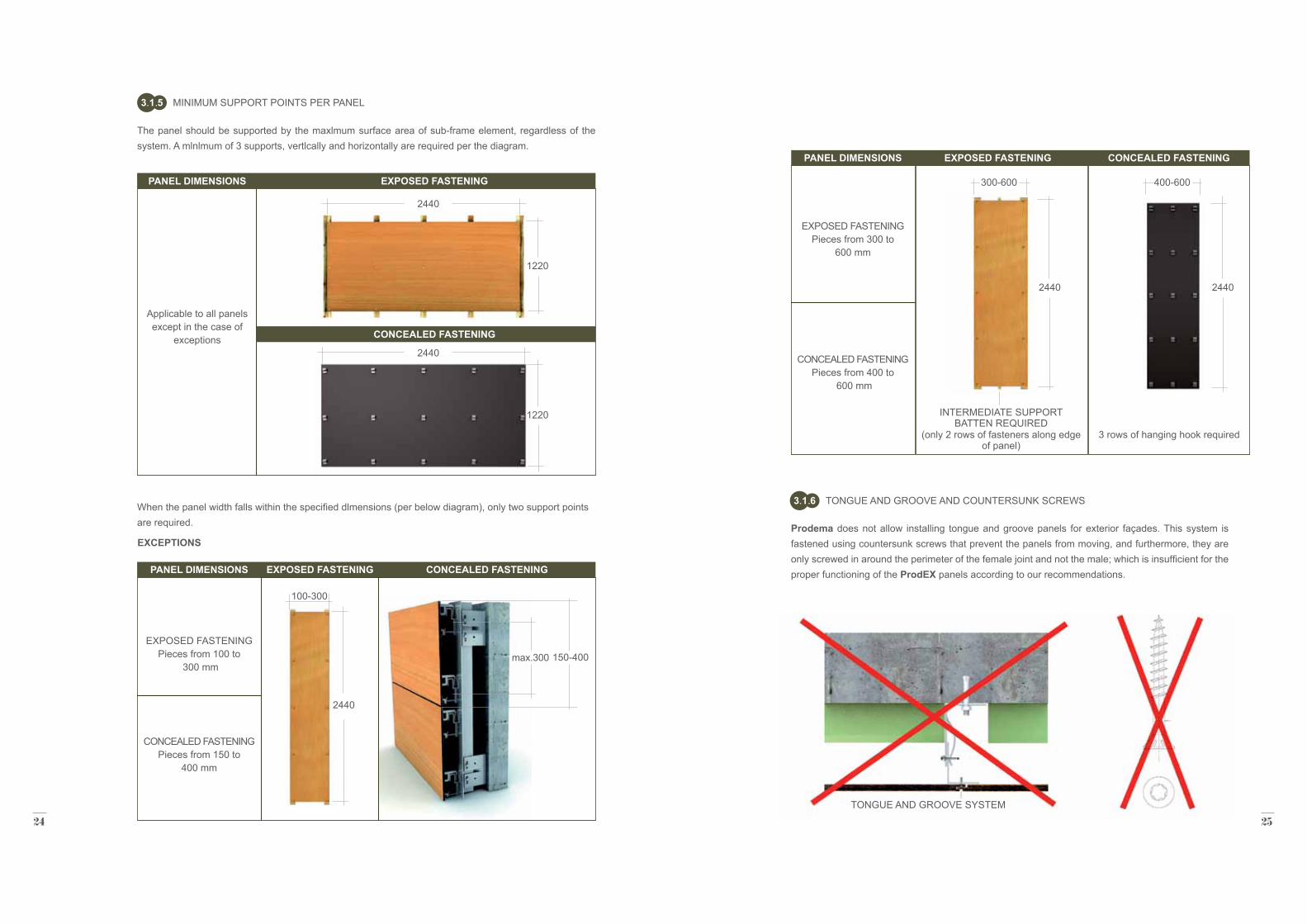
TONGUE AND GROOVE AND COUNTERSUNK SCREWS3 1 6
Prodema does not allow installing tongue and groove panels for exterior façades. This system is fastened using countersunk screws that prevent the panels from moving, and furthermore, they are only screwed in around the perimeter of the female joint and not the male; which is insufficient for the proper functioning of the ProdEX panels according to our recommendations.
TONGUE AND GROOVE SYSTEM
MINIMUM SUPPORT POINTS PER PANEL
The panel should be supported by the maxlmum surface area of sub-frame element, regardless of the system. A mlnlmum of 3 supports, vertlcally and horizontally are required per the diagram.
3 1 5
2440
2440
100-300
1220
1220
2440
When the panel width falls within the specified dlmensions (per below diagram), only two support points are required.
EXCEPTIONS
300-600 400-600
2440 2440
PANEL DIMENSIONS
Applicable to all panels except in the case of
exceptions
PANEL DIMENSIONS
EXPOSED FASTENING Pieces from 100 to
300 mm
CONCEALED FASTENING Pieces from 150 to
400 mm
PANEL DIMENSIONS
EXPOSED FASTENING
Pieces from 300 to 600 mm
CONCEALED FASTENING
Pieces from 400 to 600 mm
INTERMEDIATE SUPPORT BATTEN REQUIRED
(only 2 rows of fasteners along edge of panel)
3 rows of hanging hook required
EXPOSED FASTENING
CONCEALED FASTENING
EXPOSED FASTENING
EXPOSED FASTENING
CONCEALED FASTENING
CONCEALED FASTENING
max.300 150-400
26 27
INSTALLATION SYSTEMS3 2
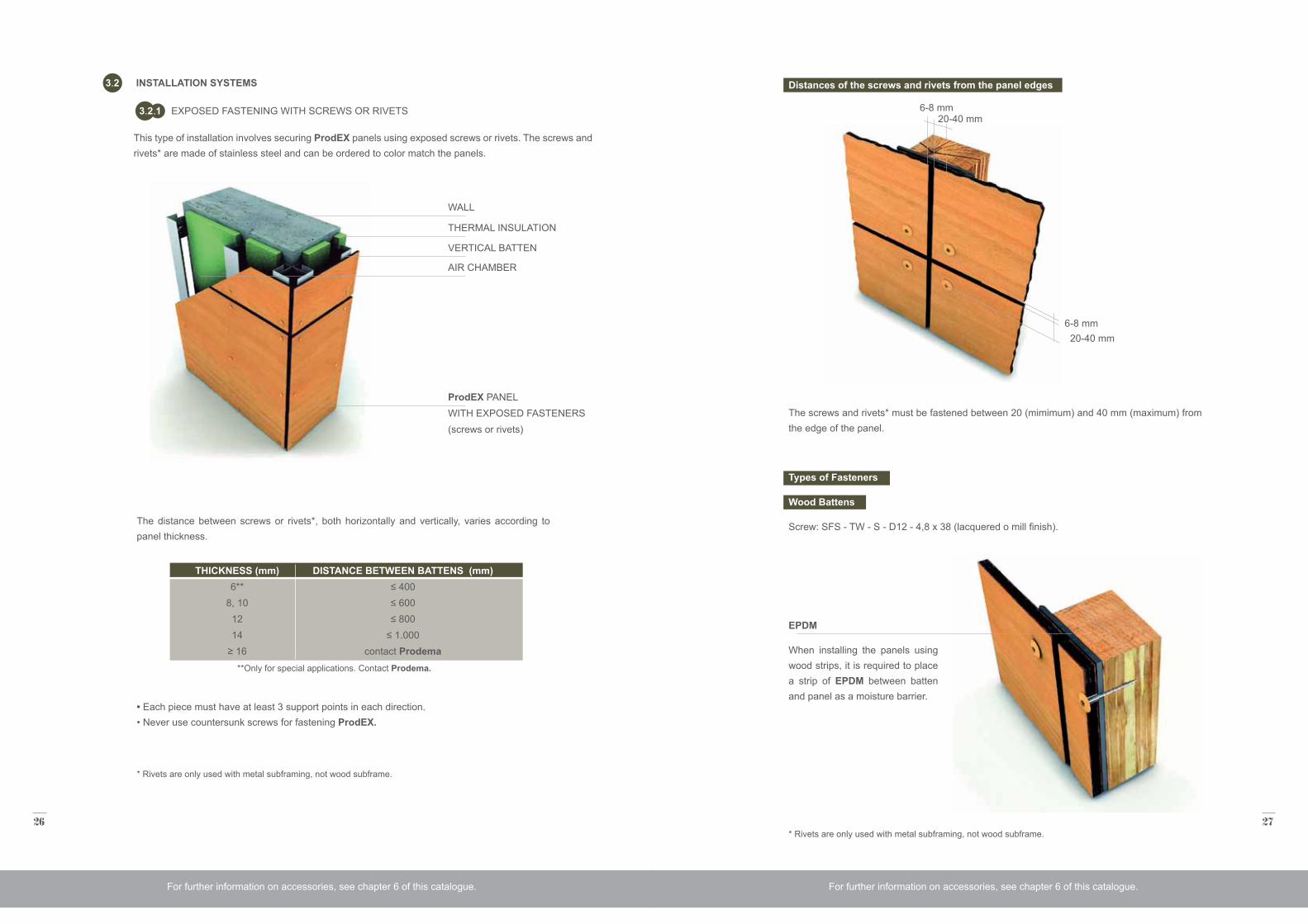
EXPOSED FASTENING WITH SCREWS OR RIVETS3 2 1
This type of installation involves securing ProdEX panels using exposed screws or rivets. The screws and rivets* are made of stainless steel and can be ordered to color match the panels.
* Rivets are only used with metal subframing, not wood subframe.
**Only for special applications. Contact Prodema.
WALL
THERMAL INSULATION
VERTICAL BATTEN
AIR CHAMBER
ProdEX PANELWITH EXPOSED FASTENERS(screws or rivets)
The distance between screws or rivets*, both horizontally and vertically, varies according to panel thickness.
• Each piece must have at least 3 support points in each direction. • Never use countersunk screws for fastening ProdEX.
THICKNESS (mm)6**
8, 101214
≥ 16
DISTANCE BETWEEN BATTENS (mm)≤ 400≤ 600≤ 800
≤ 1.000contact Prodema
Distances of the screws and rivets from the panel edges
Types of Fasteners
Wood Battens
Screw: SFS - TW - S - D12 - 4,8 x 38 (lacquered o mill finish).
The screws and rivets* must be fastened between 20 (mimimum) and 40 mm (maximum) from the edge of the panel.
* Rivets are only used with metal subframing, not wood subframe.
EPDM
When installing the panels using wood strips, it is required to place a strip of EPDM between batten and panel as a moisture barrier.
6-8 mm
6-8 mm
20-40 mm
20-40 mm
For further information on accessories, see chapter 6 of this catalogue. For further information on accessories, see chapter 6 of this catalogue.
28 29
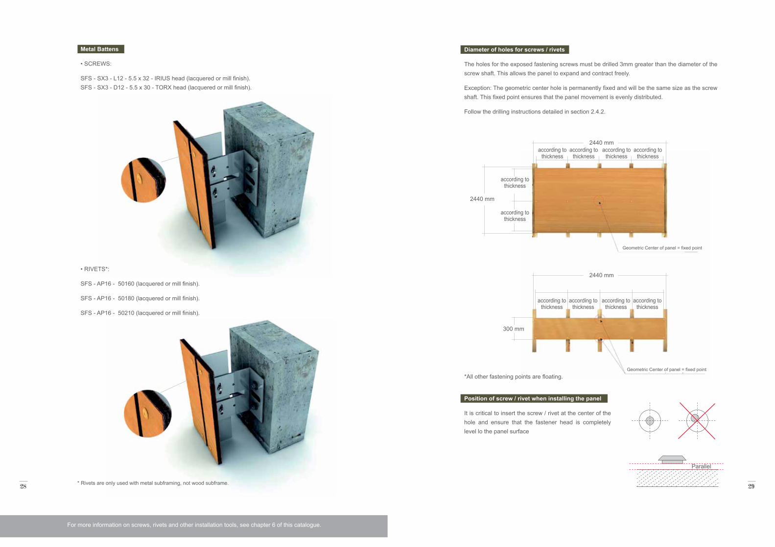
Metal Battens
• SCREWS:
SFS - SX3 - L12 - 5.5 x 32 - IRIUS head (lacquered or mill finish). SFS - SX3 - D12 - 5.5 x 30 - TORX head (lacquered or mill finish).
* Rivets are only used with metal subframing, not wood subframe.
Diameter of holes for screws / rivets
The holes for the exposed fastening screws must be drilled 3mm greater than the diameter of the screw shaft. This allows the panel to expand and contract freely.
Exception: The geometric center hole is permanently fixed and will be the same size as the screw shaft. This fixed point ensures that the panel movement is evenly distributed.
Follow the drilling instructions detailed in section 2.4.2.
Position of screw / rivet when installing the panel
It is critical to insert the screw / rivet at the center of the hole and ensure that the fastener head is completely level lo the panel surface
Parallel
For more information on screws, rivets and other installation tools, see chapter 6 of this catalogue.
• RIVETS*:
SFS - AP16 - 50160 (lacquered or mill finish).
SFS - AP16 - 50180 (lacquered or mill finish).
SFS - AP16 - 50210 (lacquered or mill finish).
2440 mm
2440 mm
according to thickness
according to thickness
according to thickness
according to thickness
according to thickness
according to thickness
according to thickness
according to thickness
according to thickness
according to thickness
2440 mm
300 mm
Geometric Center of panel = fixed point
*All other fastening points are floating.Geometric Center of panel = fixed point
30 31
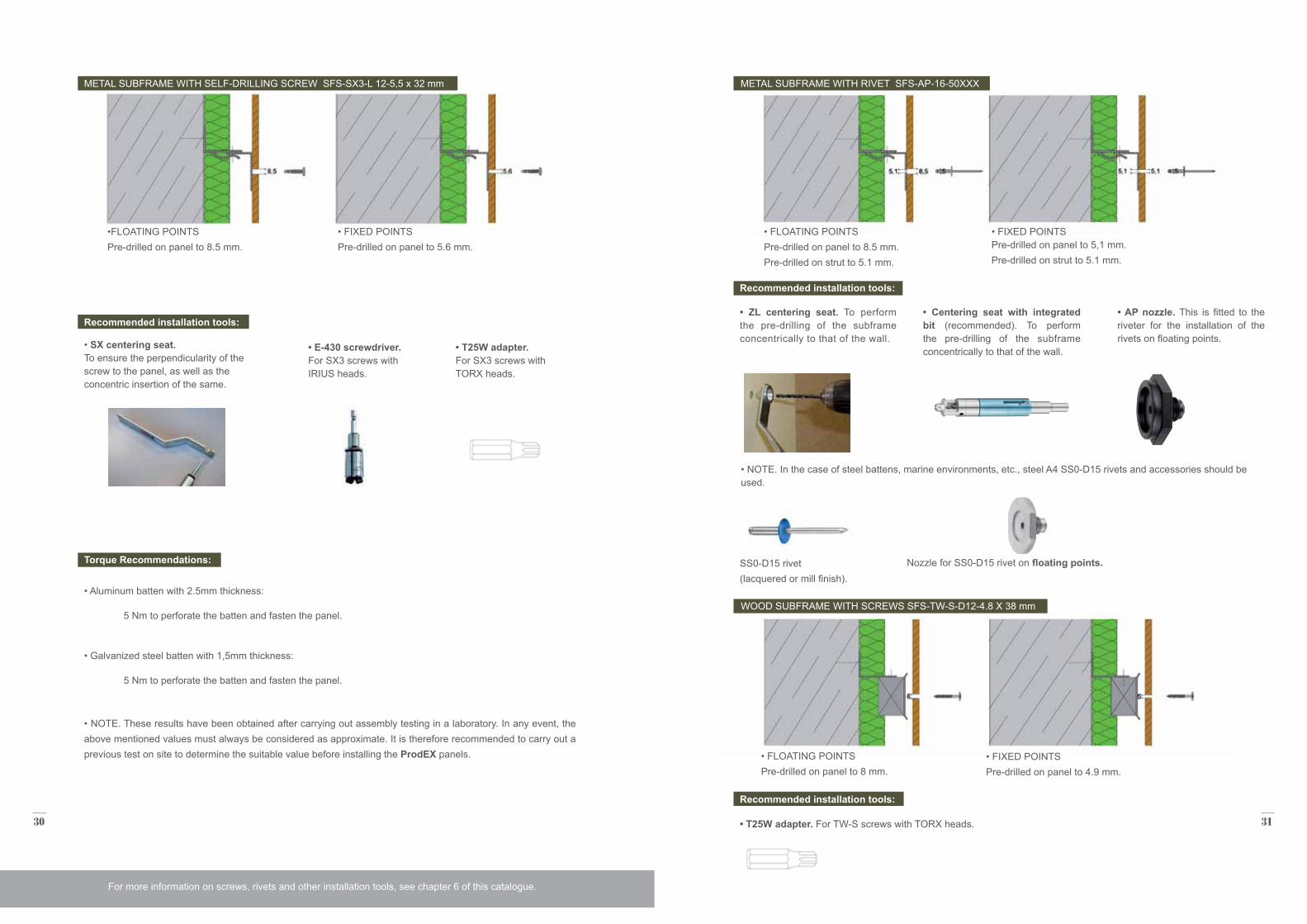
•FLOATING POINTS Pre-drilled on panel to 8.5 mm.
Recommended installation tools:
• SX centering seat. To ensure the perpendicularity of the screw to the panel, as well as the concentric insertion of the same.
Recommended installation tools:
• ZL centering seat. To perform the pre-drilling of the subframe concentrically to that of the wall.
Recommended installation tools:
• T25W adapter. For TW-S screws with TORX heads.
• E-430 screwdriver. For SX3 screws with IRIUS heads.
• Centering seat with integrated bit (recommended). To perform the pre-drilling of the subframe concentrically to that of the wall.
• AP nozzle. This is fitted to the riveter for the installation of the rivets on floating points.
• NOTE. In the case of steel battens, marine environments, etc., steel A4 SS0-D15 rivets and accessories should be used.
• T25W adapter. For SX3 screws with TORX heads.
• Aluminum batten with 2.5mm thickness:
5 Nm to perforate the batten and fasten the panel.
• Galvanized steel batten with 1,5mm thickness:
5 Nm to perforate the batten and fasten the panel.
Torque Recommendations: SS0-D15 rivet (lacquered or mill finish).
Nozzle for SS0-D15 rivet on floating points.
• FLOATING POINTS Pre-drilled on panel to 8.5 mm. Pre-drilled on strut to 5.1 mm.
• FIXED POINTS Pre-drilled on panel to 5.6 mm.
• FIXED POINTS Pre-drilled on panel to 5,1 mm. Pre-drilled on strut to 5.1 mm.
METAL SUBFRAME WITH SELF-DRILLING SCREW SFS-SX3-L 12-5,5 x 32 mm METAL SUBFRAME WITH RIVET SFS-AP-16-50XXX
For more information on screws, rivets and other installation tools, see chapter 6 of this catalogue.
• FLOATING POINTS Pre-drilled on panel to 8 mm.
• FIXED POINTS Pre-drilled on panel to 4.9 mm.
WOOD SUBFRAME WITH SCREWS SFS-TW-S-D12-4.8 X 38 mm
• NOTE. These results have been obtained after carrying out assembly testing in a laboratory. In any event, the above mentioned values must always be considered as approximate. It is therefore recommended to carry out a previous test on site to determine the suitable value before installing the ProdEX panels.
32 33
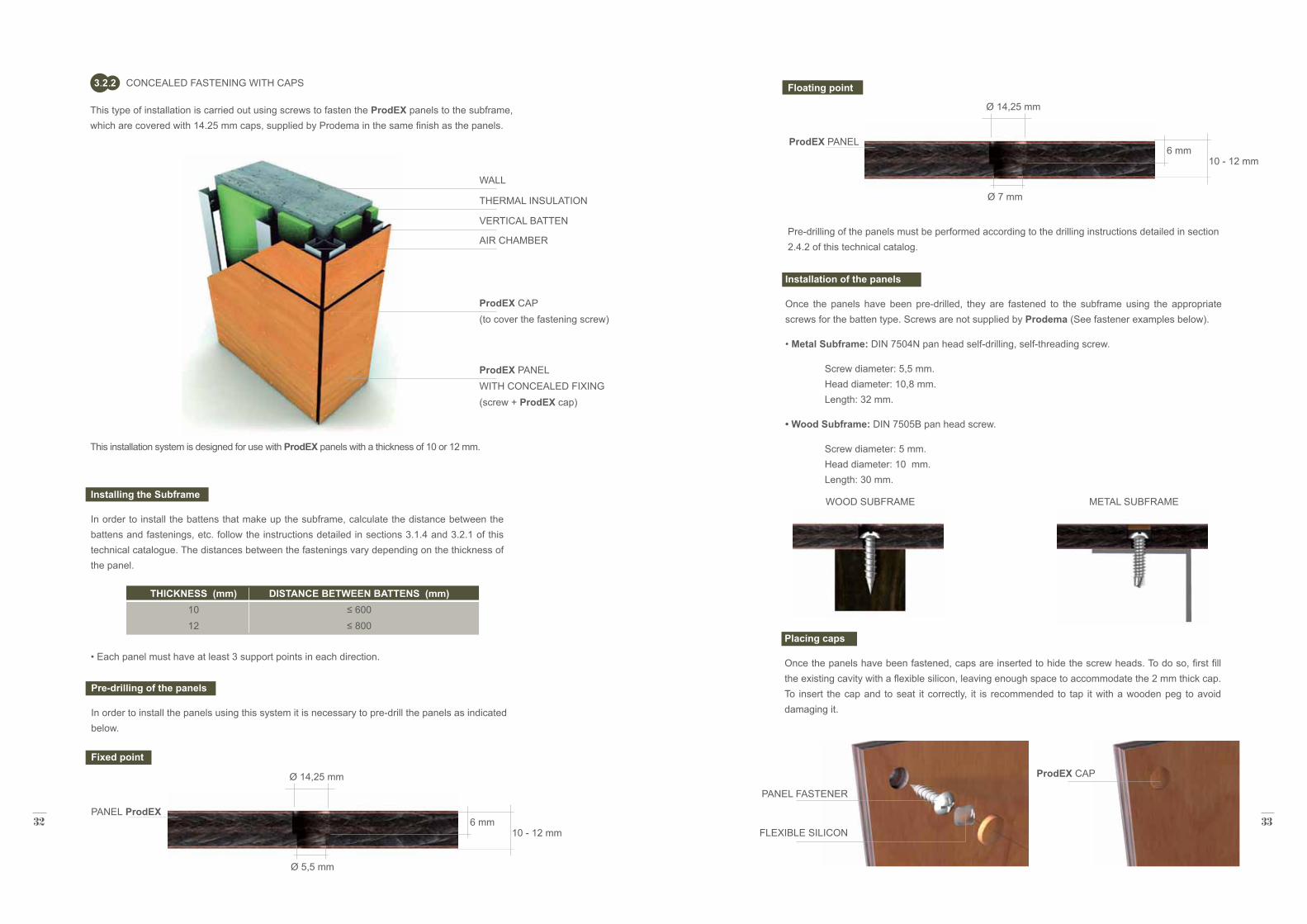
This type of installation is carried out using screws to fasten the ProdEX panels to the subframe, which are covered with 14.25 mm caps, supplied by Prodema in the same finish as the panels.
This installation system is designed for use with ProdEX panels with a thickness of 10 or 12 mm.
WALL
THERMAL INSULATION
VERTICAL BATTEN
AIR CHAMBER
ProdEX CAP(to cover the fastening screw)
ProdEX PANELWITH CONCEALED FIXING(screw + ProdEX cap)
CONCEALED FASTENING WITH CAPS3 2 2
Installing the Subframe
In order to install the battens that make up the subframe, calculate the distance between the battens and fastenings, etc. follow the instructions detailed in sections 3.1.4 and 3.2.1 of this technical catalogue. The distances between the fastenings vary depending on the thickness of the panel.
THICKNESS (mm)1012
DISTANCE BETWEEN BATTENS (mm)≤ 600≤ 800
• Each panel must have at least 3 support points in each direction.
Pre-drilling of the panels
In order to install the panels using this system it is necessary to pre-drill the panels as indicated below.
Pre-drilling of the panels must be performed according to the drilling instructions detailed in section 2.4.2 of this technical catalog.
Fixed point
Floating point
PANEL ProdEX
ProdEX PANEL
Ø 14,25 mm
Ø 14,25 mm
10 - 12 mm
10 - 12 mm
6 mm
6 mm
Ø 5,5 mm
Ø 7 mm
Installation of the panels
Once the panels have been pre-drilled, they are fastened to the subframe using the appropriate screws for the batten type. Screws are not supplied by Prodema (See fastener examples below).
• Metal Subframe: DIN 7504N pan head self-drilling, self-threading screw.
Screw diameter: 5,5 mm. Head diameter: 10,8 mm. Length: 32 mm.
• Wood Subframe: DIN 7505B pan head screw.
Screw diameter: 5 mm. Head diameter: 10 mm. Length: 30 mm.
WOOD SUBFRAME METAL SUBFRAME
FLEXIBLE SILICON
Placing caps
Once the panels have been fastened, caps are inserted to hide the screw heads. To do so, first fill the existing cavity with a flexible silicon, leaving enough space to accommodate the 2 mm thick cap. To insert the cap and to seat it correctly, it is recommended to tap it with a wooden peg to avoid damaging it.
PANEL FASTENER
ProdEX CAP
34 35
Recommended distance: 1 - 1.25 m
distan
ce ac
cordi
ng
to thi
ckne
ss*
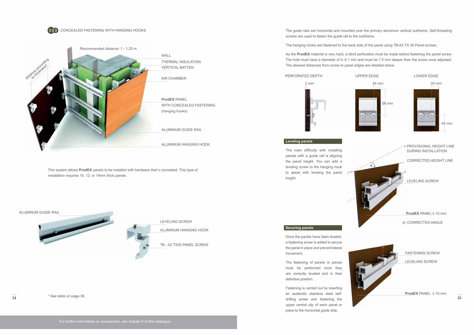
CONCEALED FASTENING WITH HANGING HOOKS3 2 3
WALL
LEVELING SCREW
THERMAL INSULATION
ALUMINUM HANGING HOOK
VERTICAL BATTEN
TB - A2 TX30 PANEL SCREW
AIR CHAMBER
ALUMINUM GUIDE RAIL
ALUMINUM HANGING HOOK
ProdEX PANELWITH CONCEALED FASTENING(hanging hooks)
This system allows ProdEX panels to be installed with hardware that´s concealed. This type of installation requires 10, 12, or 14mm thick panels.
ALUMINUM GUIDE RAIL
* See table on page 36.
For further information on accessories, see chapter 6 of this catalogue.
The guide rails are horizontal and mounted over the primary aluminum vertical subframe. Self-threading screws are used to fasten the guide rail to the subframe.
The hanging hooks are fastened to the back side of the panel using TB-A2 TX 30 Panel screws.
As the ProdEX material is very hard, a blind perforation must be made before fastening the panel screw. The hole must have a diameter of 5–5.1 mm and must be 1.5 mm deeper than the screw once adjusted. The allowed distances from screw to panel edges are detailed below.
Leveling panels
The main difficulty with installing panels with a guide rail is aligning the panel height. You can add a leveling screw to the hanging hook to assist with leveling the panel height.
Securing panels
Once the panels have been leveled, a fastening screw is added to secure the panel in place and prevent lateral movement.
The fastening of panels or pieces must be performed once they are correctly leveled and in their definitive position.
Fastening is carried out by inserting an austenitic stainless steel self-drilling screw and fastening the upper central clip of each panel or piece to the horizontal guide strip.
58 mm
45 mm
2 mm 24 mm 24 mm
PROVISIONAL HEIGHT LINE DURING INSTALLATION
=
=
: CORRECTED ANGLE
CORRECTED HEIGHT LINE
LEVELING SCREW
LEVELING SCREW
FASTENING SCREW
ProdEX PANEL ≥ 10 mm
ProdEX PANEL ≥ 10 mm
PERFORATED DEPTH UPPER EDGE LOWER EDGE
36 37
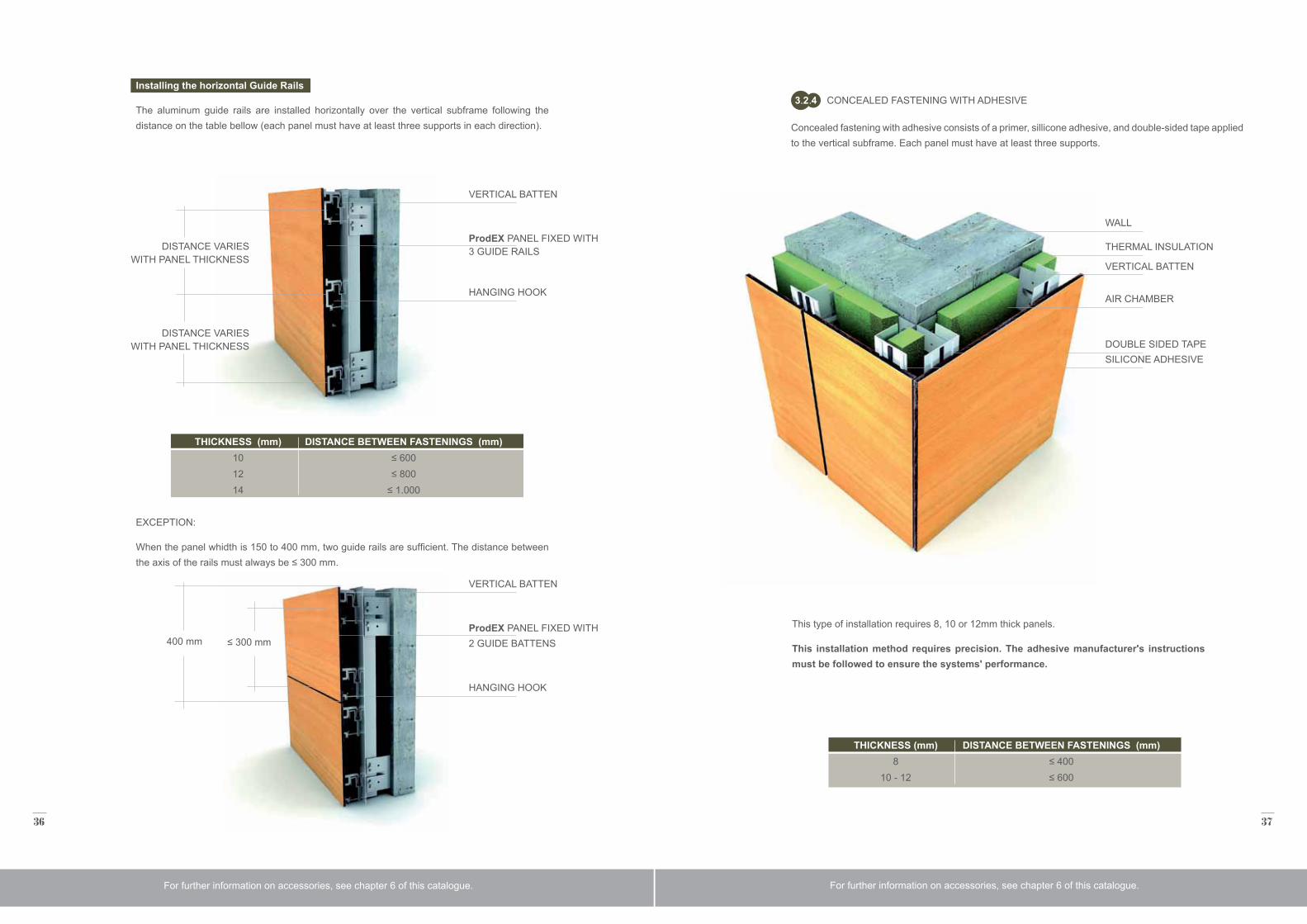
Installing the horizontal Guide Rails
The aluminum guide rails are installed horizontally over the vertical subframe following the distance on the table bellow (each panel must have at least three supports in each direction).
EXCEPTION:
When the panel whidth is 150 to 400 mm, two guide rails are sufficient. The distance between the axis of the rails must always be ≤ 300 mm.
VERTICAL BATTEN
VERTICAL BATTEN
DISTANCE VARIES WITH PANEL THICKNESS
DISTANCE VARIES WITH PANEL THICKNESS
≤ 300 mm400 mm
ProdEX PANEL FIXED WITH 3 GUIDE RAILS
ProdEX PANEL FIXED WITH 2 GUIDE BATTENS
HANGING HOOK
HANGING HOOK
THICKNESS (mm)101214
DISTANCE BETWEEN FASTENINGS (mm)≤ 600≤ 800
≤ 1.000
For further information on accessories, see chapter 6 of this catalogue.
CONCEALED FASTENING WITH ADHESIVE3 2 4
WALL
THERMAL INSULATION
VERTICAL BATTEN
AIR CHAMBER
DOUBLE SIDED TAPE SILICONE ADHESIVE
This type of installation requires 8, 10 or 12mm thick panels.
This installation method requires precision. The adhesive manufacturer's instructions must be followed to ensure the systems' performance.
THICKNESS (mm)8
10 - 12
DISTANCE BETWEEN FASTENINGS (mm)≤ 400≤ 600
Concealed fastening with adhesive consists of a primer, sillicone adhesive, and double-sided tape applied to the vertical subframe. Each panel must have at least three supports.
For further information on accessories, see chapter 6 of this catalogue.
38 39
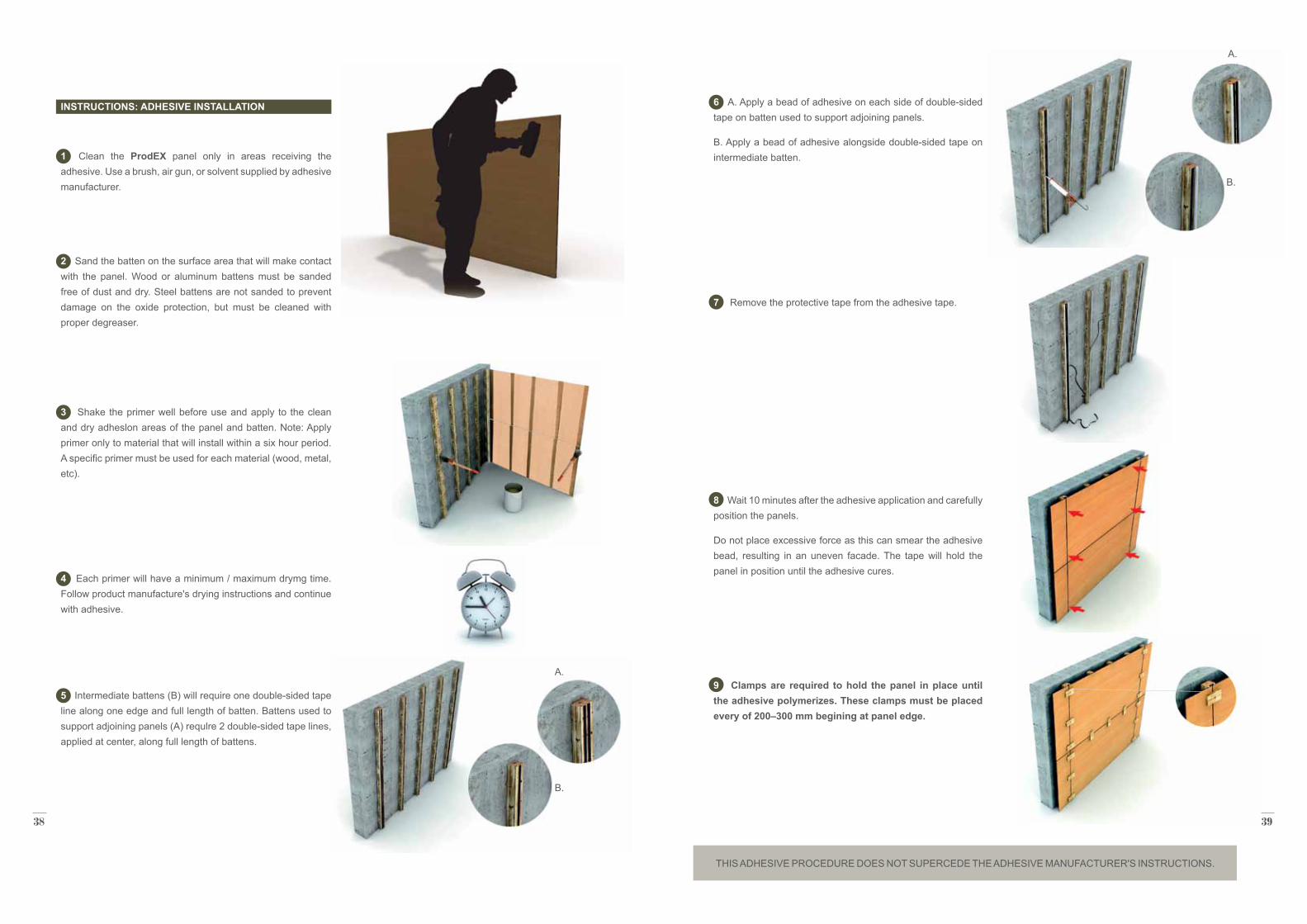
INSTRUCTIONS: ADHESIVE INSTALLATION
1 Clean the ProdEX panel only in areas receiving the adhesive. Use a brush, air gun, or solvent supplied by adhesive manufacturer.
2 Sand the batten on the surface area that will make contact with the panel. Wood or aluminum battens must be sanded free of dust and dry. Steel battens are not sanded to prevent damage on the oxide protection, but must be cleaned with proper degreaser.
3 Shake the primer well before use and apply to the clean and dry adheslon areas of the panel and batten. Note: Apply primer only to material that will install within a six hour period. A specific primer must be used for each material (wood, metal, etc).
4 Each primer will have a minimum / maximum drymg time. Follow product manufacture's drying instructions and continue with adhesive.
5 Intermediate battens (B) will require one double-sided tape line along one edge and full length of batten. Battens used to support adjoining panels (A) requlre 2 double-sided tape lines, applied at center, along full length of battens.
A.
B.
6 A. Apply a bead of adhesive on each side of double-sided tape on batten used to support adjoining panels.
B. Apply a bead of adhesive alongside double-sided tape on intermediate batten.
7 Remove the protective tape from the adhesive tape.
8 Wait 10 minutes after the adhesive application and carefully position the panels.
Do not place excessive force as this can smear the adhesive bead, resulting in an uneven facade. The tape will hold the panel in position until the adhesive cures.
9 Clamps are required to hold the panel in place until the adhesive polymerizes. These clamps must be placed every of 200–300 mm begining at panel edge.
A.
B.
THIS ADHESIVE PROCEDURE DOES NOT SUPERCEDE THE ADHESIVE MANUFACTURER'S INSTRUCTIONS.
40 41
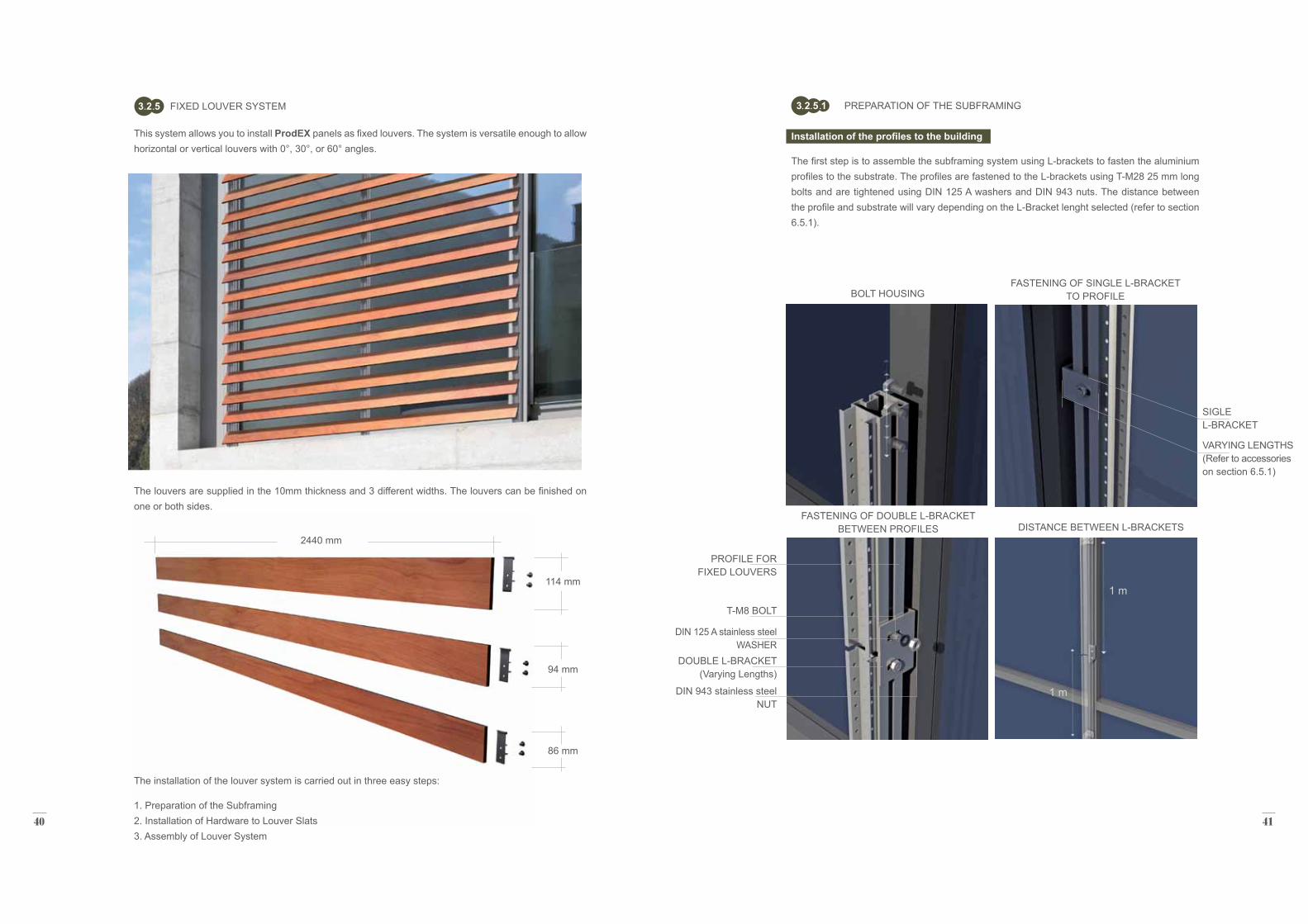
FIXED LOUVER SYSTEM3 2 5
This system allows you to install ProdEX panels as fixed louvers. The system is versatile enough to allow horizontal or vertical louvers with 0°, 30°, or 60° angles.
The louvers are supplied in the 10mm thickness and 3 different widths. The louvers can be finished on one or both sides.
The installation of the louver system is carried out in three easy steps:
1. Preparation of the Subframing 2. Installation of Hardware to Louver Slats 3. Assembly of Louver System
114 mm
2440 mm
94 mm
86 mm
PREPARATION OF THE SUBFRAMING3 2 5 1
FASTENING OF SINGLE L-BRACKET TO PROFILE
DISTANCE BETWEEN L-BRACKETSFASTENING OF DOUBLE L-BRACKET
BETWEEN PROFILES
BOLT HOUSING
PROFILE FOR FIXED LOUVERS
T-M8 BOLT
DIN 943 stainless steel NUT
DIN 125 A stainless steel WASHER
DOUBLE L-BRACKET (Varying Lengths)
SIGLE L-BRACKET
VARYING LENGTHS (Refer to accessories on section 6.5.1)
Installation of the profiles to the building
The first step is to assemble the subframing system using L-brackets to fasten the aluminium profiles to the substrate. The profiles are fastened to the L-brackets using T-M28 25 mm long bolts and are tightened using DIN 125 A washers and DIN 943 nuts. The distance between the profile and substrate will vary depending on the L-Bracket lenght selected (refer to section 6.5.1).
1 m
1 m
42 43
The louver orientation determines whether the profiles are installed vertically or horizontally. Horizontal louvers require vertical profiles and vertical louvers require horizontal profiles.
Accessories are available in mill, black, RAL or FUTURA colors (refer to Accesories in Section 6).
It is crucial to perfectly align profiles as failing to do so will result in uneven louvers.
Fixed louvers also require vertical and horizontal joint spacing and air cavity behind panels to promote ventilation (refer to sections 3.1.1 and 3.1.2).
INSTALLATION OF PROFILES FOR HORIZONTAL LOUVERS
INSTALLATION OF PROFILES FOR VERTICAL LOUVERS
INSTALLATION OF BASE PART
SELF-THREADING SCREW DIN 7981 5.5 x 13 stainless steel
Installation of the Base Parts to Profiles
Afler installing the profiles, the angled or flat base parts must be installed.These pieces are fastened to the profiles by inserting austenitic stainless steel DIN 7981 fasteners into the holes on each side (see image below). Note that the profiles are supplied with pre-drilled holes every 20mm. Although this distance is standard, the profiles can be supplied without perforations, upon request.
For further information on accessories, see chapter 6 of this catalogue.
20 mm
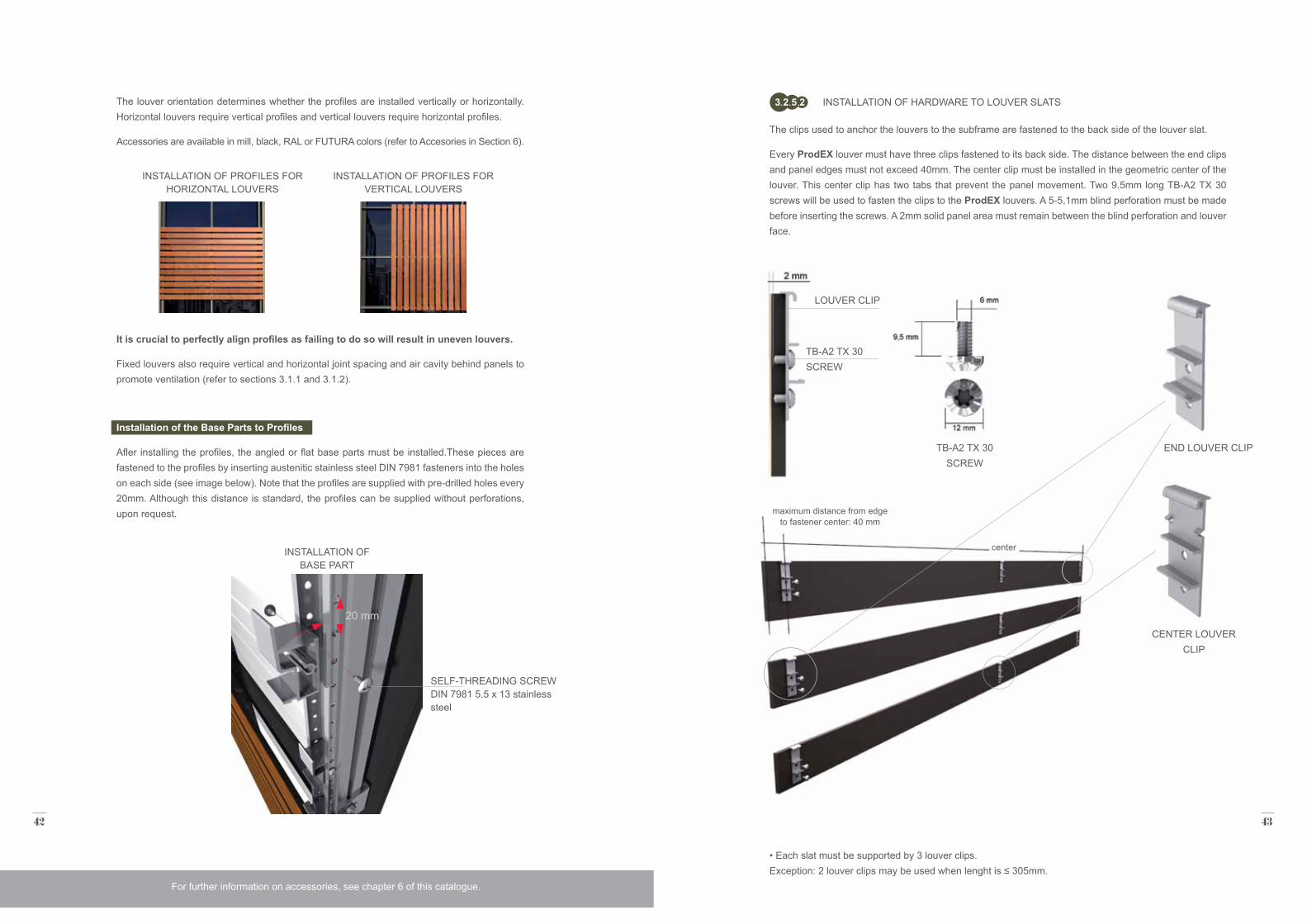
The clips used to anchor the louvers to the subframe are fastened to the back side of the louver slat.
Every ProdEX louver must have three clips fastened to its back side. The distance between the end clips and panel edges must not exceed 40mm. The center clip must be installed in the geometric center of the louver. This center clip has two tabs that prevent the panel movement. Two 9.5mm long TB-A2 TX 30 screws will be used to fasten the clips to the ProdEX louvers. A 5-5,1mm blind perforation must be made before inserting the screws. A 2mm solid panel area must remain between the blind perforation and louver face.
INSTALLATION OF HARDWARE TO LOUVER SLATS3 2 5 2
TB-A2 TX 30 SCREW
TB-A2 TX 30 SCREW
LOUVER CLIP
• Each slat must be supported by 3 louver clips. Exception: 2 louver clips may be used when lenght is ≤ 305mm.
CENTER LOUVER CLIP
END LOUVER CLIP
maximum distance from edge to fastener center: 40 mm
center
44 45
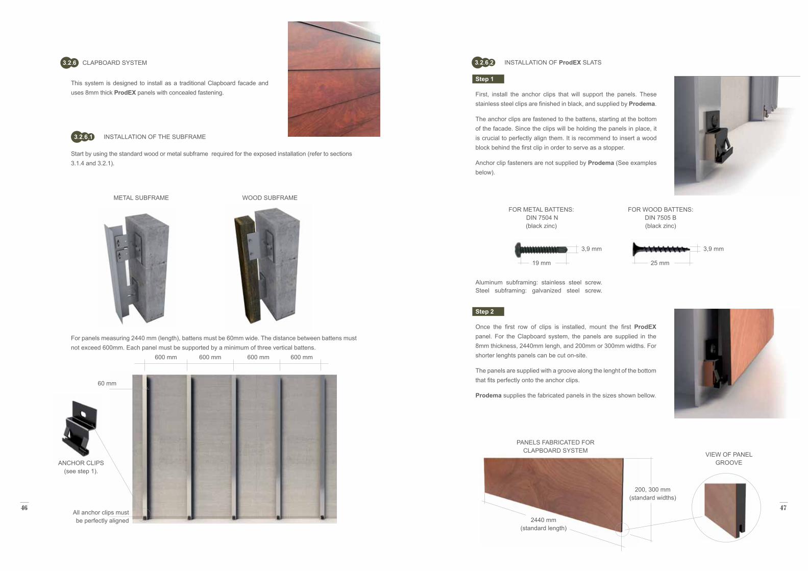
DOUBLE BASE PART FOR ANGLED FIXED LOUVERS (60º)*
BASE PART FOR ANGLED FIXED LOUVERS (30º) INSTALLATION OF
ADJOINING LOUVERS
INSTALLATION OF THE DOUBLE BASE PART
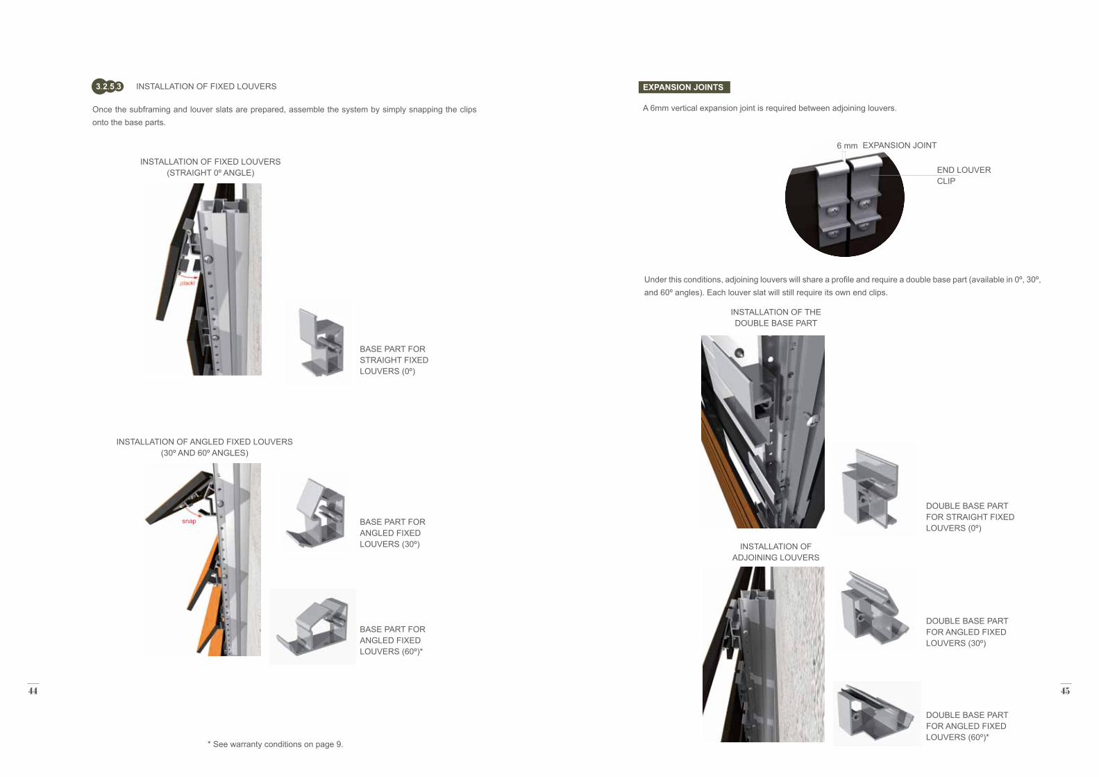
Once the subframing and louver slats are prepared, assemble the system by simply snapping the clips onto the base parts.
INSTALLATION OF FIXED LOUVERS3 2 5 3
INSTALLATION OF FIXED LOUVERS (STRAIGHT 0º ANGLE)
INSTALLATION OF ANGLED FIXED LOUVERS (30º AND 60º ANGLES)
BASE PART FOR STRAIGHT FIXED LOUVERS (0º)
BASE PART FOR ANGLED FIXED LOUVERS (60º)*
EXPANSION JOINT
END LOUVER CLIP
6 mm
EXPANSION JOINTS
A 6mm vertical expansion joint is required between adjoining louvers.
Under this conditions, adjoining louvers will share a profile and require a double base part (available in 0º, 30º, and 60º angles). Each louver slat will still require its own end clips.
DOUBLE BASE PART FOR ANGLED FIXED LOUVERS (30º)
DOUBLE BASE PART FOR STRAIGHT FIXED LOUVERS (0º)
* See warranty conditions on page 9.
snap
46 47
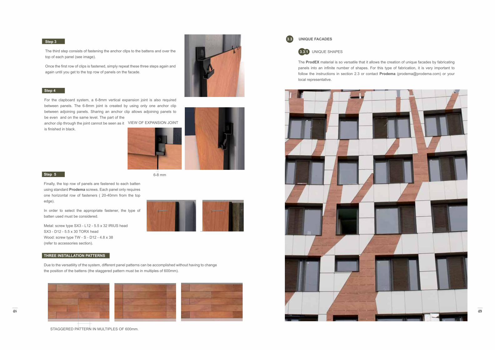
This system is designed to install as a traditional Clapboard facade and uses 8mm thick ProdEX panels with concealed fastening.
Start by using the standard wood or metal subframe required for the exposed installation (refer to sections 3.1.4 and 3.2.1).
INSTALLATION OF THE SUBFRAME3 2 6 1
CLAPBOARD SYSTEM3 2 6
60 mm
3,9 mm 3,9 mm
19 mm 25 mm
600 mm 600 mm 600 mm 600 mm
2440 mm (standard length)
200, 300 mm (standard widths)
For panels measuring 2440 mm (length), battens must be 60mm wide. The distance between battens must not exceed 600mm. Each panel must be supported by a minimum of three vertical battens.
All anchor clips must be perfectly aligned
Step 1
First, install the anchor clips that will support the panels. These stainless steel clips are finished in black, and supplied by Prodema.
The anchor clips are fastened to the battens, starting at the bottom of the facade. Since the clips will be holding the panels in place, it is crucial to perfectly align them. It is recommend to insert a wood block behind the first clip in order to serve as a stopper.
Anchor clip fasteners are not supplied by Prodema (See examples below).
Step 2
Once the first row of clips is installed, mount the first ProdEX panel. For the Clapboard system, the panels are supplied in the 8mm thickness, 2440mm lengh, and 200mm or 300mm widths. For shorter lenghts panels can be cut on-site.
The panels are supplied with a groove along the lenght of the bottom that fits perfectly onto the anchor clips.
Prodema supplies the fabricated panels in the sizes shown bellow.
INSTALLATION OF ProdEX SLATS3 2 6 2
VIEW OF PANEL GROOVE
PANELS FABRICATED FOR CLAPBOARD SYSTEM
FOR METAL BATTENS: DIN 7504 N (black zinc)
Aluminum subframing: stainless steel screw. Steel subframing: galvanized steel screw.
FOR WOOD BATTENS: DIN 7505 B (black zinc)
METAL SUBFRAME WOOD SUBFRAME
ANCHOR CLIPS (see step 1).
48 49
Step 4
For the clapboard system, a 6-8mm vertical expansion joint is also required between panels. The 6-8mm joint is created by using only one anchor clip between adjoining panels. Sharing an anchor clip allows adjoining panels to be even and on the same level. The part of the anchor clip through the joint cannot be seen as it is finished in black.
Step 5
Finally, the top row of panels are fastened to each batten using standard Prodema screws. Each panel only requires one horizontal row of fasteners ( 20-40mm from the top edge).
In order to select the appropriate fastener, the type of batten used must be considered.
Metal: screw type SX3 - L12 - 5.5 x 32 IRIUS head SX3 - D12 - 5.5 x 30 TORX head Wood: screw type TW - S - D12 - 4.8 x 38 (refer to accessories section).
THREE INSTALLATION PATTERNS
Due to the versatility of the system, different panel patterns can be accomplished without having to change the position of the battens (the staggered pattern must be in multiples of 600mm).
Step 3
The third step consists of fastening the anchor cllps to the battens and over the top of each panel (see image).
Once the first row of clips is fastened, simply repeat these three steps again and again until you get to the top row of panels on the facade.
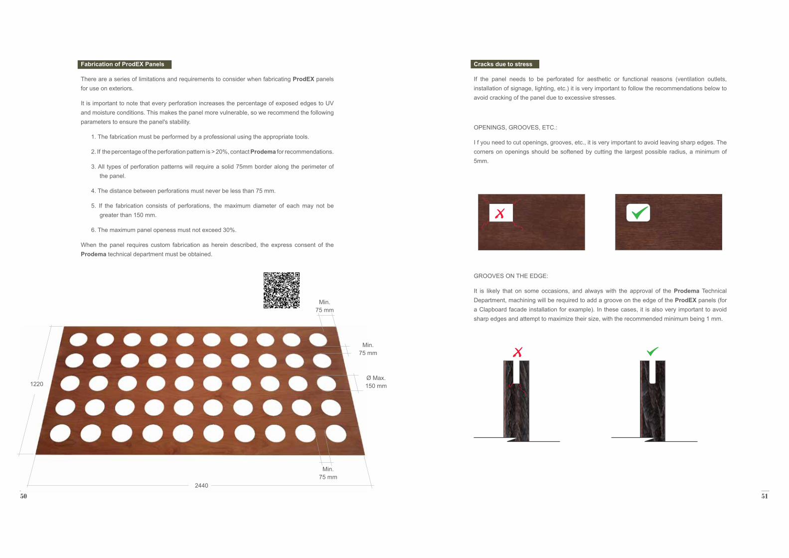
The ProdEX material is so versatile that it allows the creation of unique facades by fabricating panels into an infinite number of shapes. For this type of fabrication, it is very important to follow the instructions in section 2.3 or contact Prodema ([email protected]) or your local representative.
UNIQUE SHAPES3 3 1
UNIQUE FACADES3 3
VIEW OF EXPANSION JOINT
STAGGERED PATTERN IN MULTIPLES OF 600mm.
6-8 mm
50 51
Fabrication of ProdEX Panels
There are a series of limitations and requirements to consider when fabricating ProdEX panels for use on exteriors.
It is important to note that every perforation increases the percentage of exposed edges to UV and moisture conditions. This makes the panel more vulnerable, so we recommend the following parameters to ensure the panel's stability.
1. The fabrication must be performed by a professional using the appropriate tools.
2. If the percentage of the perforation pattern is > 20%, contact Prodema for recommendations.
3. All types of perforation patterns will require a solid 75mm border along the perimeter of the panel.
4. The distance between perforations must never be less than 75 mm.
5. If the fabrication consists of perforations, the maximum diameter of each may not be greater than 150 mm.
6. The maximum panel openess must not exceed 30%.
When the panel requires custom fabrication as herein described, the express consent of the Prodema technical department must be obtained.
Cracks due to stress
If the panel needs to be perforated for aesthetic or functional reasons (ventilation outlets, installation of signage, lighting, etc.) it is very important to follow the recommendations below to avoid cracking of the panel due to excessive stresses.
OPENINGS, GROOVES, ETC.:
I f you need to cut openings, grooves, etc., it is very important to avoid leaving sharp edges. The corners on openings should be softened by cutting the largest possible radius, a minimum of 5mm.
GROOVES ON THE EDGE:
It is likely that on some occasions, and always with the approval of the Prodema Technical Department, machining will be required to add a groove on the edge of the ProdEX panels (for a Clapboard facade installation for example). In these cases, it is also very important to avoid sharp edges and attempt to maximize their size, with the recommended minimum being 1 mm.
2440
1220
Min. 75 mm
Min. 75 mm
Min. 75 mm
Ø Max. 150 mm
52 53
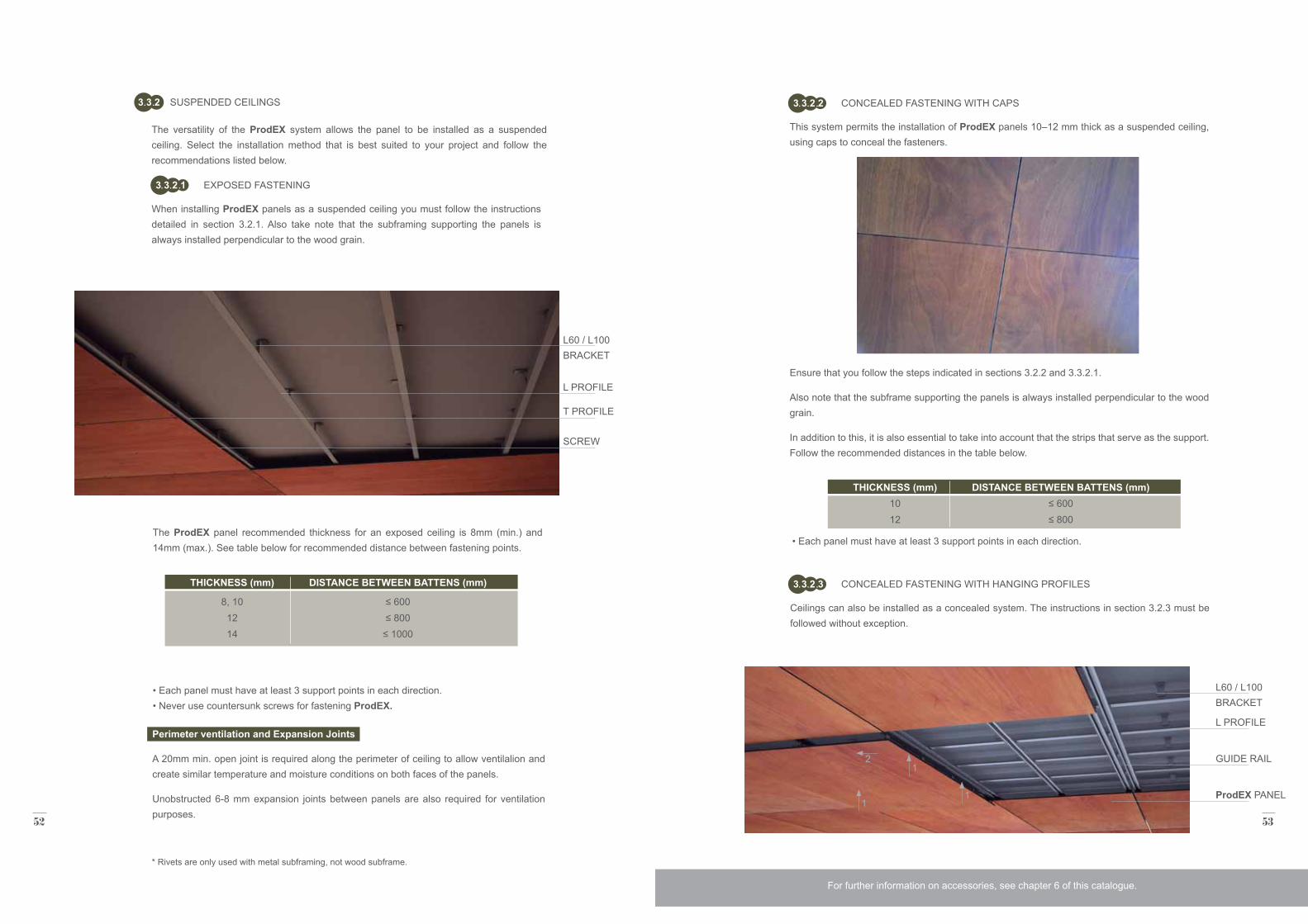
Ceilings can also be installed as a concealed system. The instructions in section 3.2.3 must be followed without exception.
The ProdEX panel recommended thickness for an exposed ceiling is 8mm (min.) and 14mm (max.). See table below for recommended distance between fastening points.
Perimeter ventilation and Expansion Joints
A 20mm min. open joint is required along the perimeter of ceiling to allow ventilalion and create similar temperature and moisture conditions on both faces of the panels.
Unobstructed 6-8 mm expansion joints between panels are also required for ventilation purposes.
THICKNESS (mm)
8, 101214
DISTANCE BETWEEN BATTENS (mm)
≤ 600≤ 800
≤ 1000
* Rivets are only used with metal subframing, not wood subframe.
• Each panel must have at least 3 support points in each direction. • Never use countersunk screws for fastening ProdEX.
This system permits the installation of ProdEX panels 10–12 mm thick as a suspended ceiling, using caps to conceal the fasteners.
Ensure that you follow the steps indicated in sections 3.2.2 and 3.3.2.1.
Also note that the subframe supporting the panels is always installed perpendicular to the wood grain.
In addition to this, it is also essential to take into account that the strips that serve as the support. Follow the recommended distances in the table below.
SUSPENDED CEILINGS3 3 2
The versatility of the ProdEX system allows the panel to be installed as a suspended ceiling. Select the installation method that is best suited to your project and follow the recommendations listed below.
When installing ProdEX panels as a suspended ceiling you must follow the instructions detailed in section 3.2.1. Also take note that the subframing supporting the panels is always installed perpendicular to the wood grain.
SCREW
ProdEX PANEL
L60 / L100 BRACKET
L60 / L100 BRACKET
T PROFILE
GUIDE RAIL
L PROFILE
L PROFILE
For further information on accessories, see chapter 6 of this catalogue.
THICKNESS (mm)1012
DISTANCE BETWEEN BATTENS (mm)≤ 600≤ 800
• Each panel must have at least 3 support points in each direction.
EXPOSED FASTENING
CONCEALED FASTENING WITH CAPS
CONCEALED FASTENING WITH HANGING PROFILES
3 3 2 1
3 3 2 2
3 3 2 3
1
11
2
54 55
CURVED SURFACES3 3 4
CURVED SURFACES WITH FACETED PANELS3 3 4 1
This system is fabricated to size and supplied as a complete kit, ready to install.
a: The maximum louver length using one continuous ProdEX panel is 2440mm. Longer lengths are possible by adjoining ProdEX panels.
b: Maximum width: 600mm.
The louvers can be designed to operate manually or by motor (synchronized or independently) using a variety of systems, such as automation centers, remote controls, sensors, etc.
The color, shape, etc., of the frame can be modified to meet the project's requirements contact Prodema ([email protected]) or your local representative.
The curving technique consists of using flat (standard) panels to create a faceted, curved surface. Select the installatlon method appropriate to the project and follow the technical instructions in this catalog.
OPERABLE LOUVERS3 3 3
In addition to our fixed louver system, Prodema offers a complete turnkey system for vertical operable louvers.
The system will adapt to each project's louver slze and motorization requirements. We will review projects on a case by case basis before making recommendations.
An aluminium frame system will be designed by Prodema per project specifications.The louver slats will fasten at both ends with a concealed or exposed attachment system.
a
b
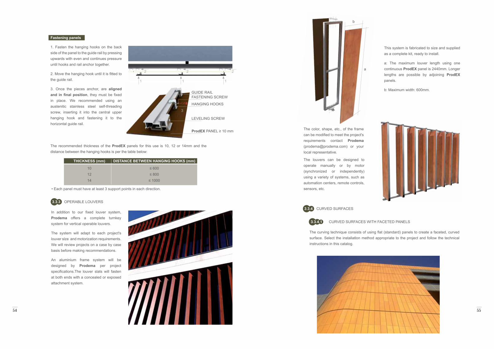
The recommended thickness of the ProdEX panels for this use is 10, 12 or 14mm and the distance between the hanging hooks is per the table below:
THICKNESS (mm)
101214
DISTANCE BETWEEN HANGING HOOKS (mm)
≤ 600≤ 800
≤ 1000
• Each panel must have at least 3 support points in each direction.
Fastening panels
1. Fasten the hanging hooks on the back side of the panel to the guide rail by pressing upwards with even and continues pressure until hooks and rail anchor together.
2. Move the hanging hook until it is fitted to the guide rail.
3. Once the pieces anchor, are aligned and in final position, they must be fixed in place. We recommended using an austenitic stainless steel self-threading screw, inserting it into the central upper hanging hook and fastening it to the horizontal guide rail.
HANGING HOOKS
LEVELING SCREW
ProdEX PANEL ≥ 10 mm
FASTENING SCREWGUIDE RAIL
3
111
2 2 2
56 57
CURVED SURFACES WITH FLAT PANELS
PRECURVED ProdEX
3 3 4 2
3 3 4 3
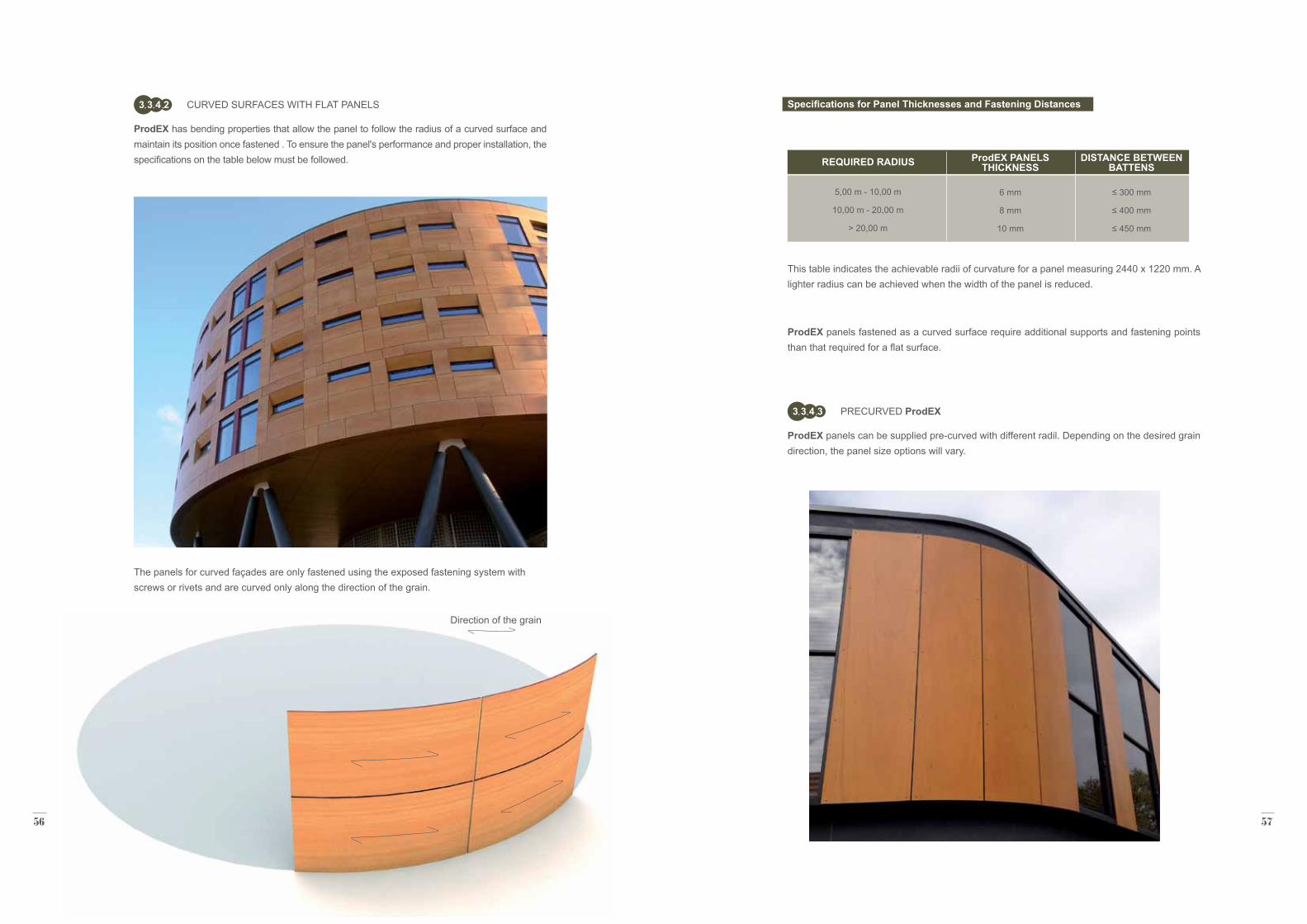
ProdEX has bending properties that allow the panel to follow the radius of a curved surface and maintain its position once fastened . To ensure the panel's performance and proper installation, the specifications on the table below must be followed.
The panels for curved façades are only fastened using the exposed fastening system with screws or rivets and are curved only along the direction of the grain.
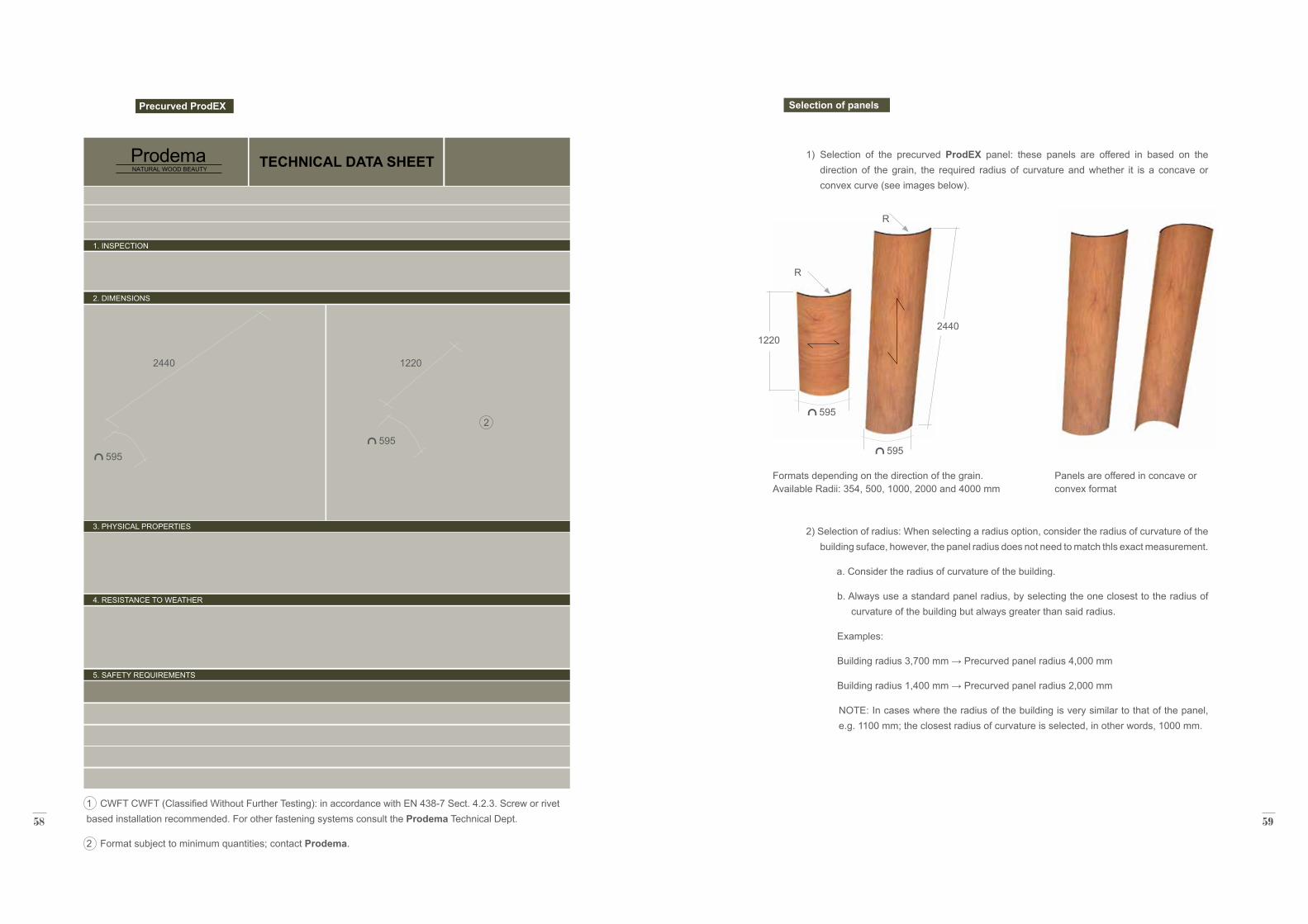
ProdEX panels can be supplied pre-curved with different radil. Depending on the desired grain direction, the panel size options will vary.
Direction of the grain
ProdEX panels fastened as a curved surface require additional supports and fastening points than that required for a flat surface.
Specifications for Panel Thicknesses and Fastening Distances
This table indicates the achievable radii of curvature for a panel measuring 2440 x 1220 mm. A lighter radius can be achieved when the width of the panel is reduced.
5,00 m - 10,00 m
10,00 m - 20,00 m
> 20,00 m
REQUIRED RADIUS ProdEX PANELS THICKNESS
6 mm
8 mm
10 mm
DISTANCE BETWEEN BATTENS
≤ 300 mm
≤ 400 mm
≤ 450 mm
58 59
Selection of panels
1) Selection of the precurved ProdEX panel: these panels are offered in based on the direction of the grain, the required radius of curvature and whether it is a concave or convex curve (see images below).
2) Selection of radius: When selecting a radius option, consider the radius of curvature of the building suface, however, the panel radius does not need to match thls exact measurement.
a. Consider the radius of curvature of the building.
b. Always use a standard panel radius, by selecting the one closest to the radius of curvature of the building but always greater than said radius.
Examples:
Building radius 3,700 mm → Precurved panel radius 4,000 mm
Building radius 1,400 mm → Precurved panel radius 2,000 mm
NOTE: In cases where the radius of the building is very similar to that of the panel, e.g. 1100 mm; the closest radius of curvature is selected, in other words, 1000 mm.
ProdemaNATURAL WOOD BEAUTY
ProdemaNATURAL WOOD BEAUTY
ProdemaNATURAL WOOD BEAUTY
TECHNICAL DATA SHEET
1. INSPECTION
2. DIMENSIONS
3. PHYSICAL PROPERTIES
4. RESISTANCE TO WEATHER
5. SAFETY REQUIREMENTS
Panels are offered in concave or convex format
Formats depending on the direction of the grain. Available Radii: 354, 500, 1000, 2000 and 4000 mm
2440 1220
595 595
Precurved ProdEX
24401220
R
R
595
595
1 CWFT CWFT (Classified Without Further Testing): in accordance with EN 438-7 Sect. 4.2.3. Screw or rivet based installation recommended. For other fastening systems consult the Prodema Technical Dept.
2 Format subject to minimum quantities; contact Prodema.
2
60 61
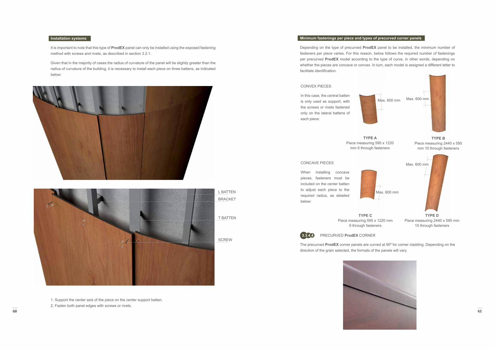
Installation systems
It is important to note that this type of ProdEX panel can only be installed using the exposed fastening method with screws and rivets, as described in section 3.2.1.
Given that in the majority of cases the radius of curvature of the panel will be slightly greater than the radius of curvature of the building, it is necessary to install each piece on three battens, as indicated below:
1. Support the center axis of the piece on the center support batten. 2. Fasten both panel edges with screws or rivets.
2
1
2
PRECURVED ProdEX CORNER3 3 4 4
The precurved ProdEX corner panels are curved at 90º for corner cladding. Depending on the direction of the grain selected, the formats of the panels will vary.
T BATTEN
SCREW
L BATTEN
BRACKET
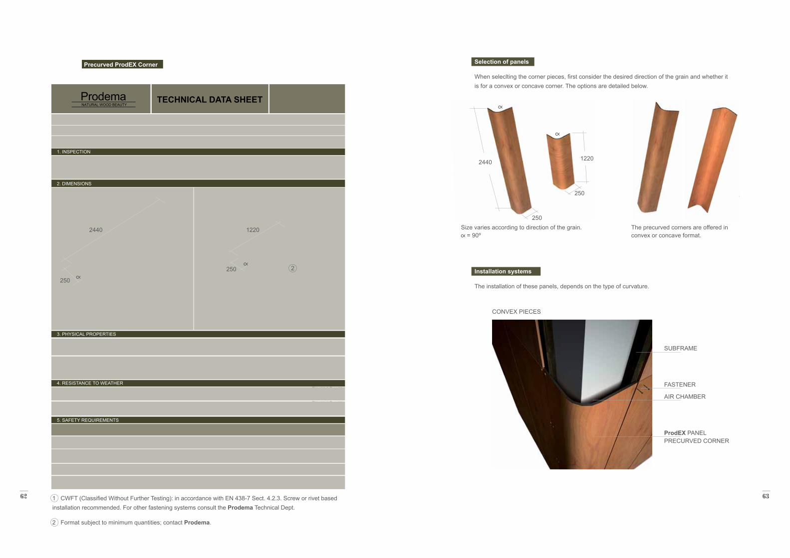
TYPE APiece measuring 595 x 1220
mm 6 through fasteners
TYPE CPiece measuring 595 x 1220 mm
9 through fasteners
TYPE BPiece measuring 2440 x 595
mm 10 through fasteners
TYPE DPiece measuring 2440 x 595 mm
15 through fasteners
Max. 600 mm
Max. 600 mm
Max. 600 mm
Max. 600 mm
Minimum fastenings per piece and types of precurved corner panels
Depending on the type of precurved ProdEX panel to be installed, the minimum number of fasteners per piece varies. For this reason, below follows the required number of fastenings per precurved ProdEX model according to the type of curve, in other words, depending on whether the pieces are concave or convex. In turn, each model is assigned a different letter to facilitate identification.
CONVEX PIECES
In this case, the central batten is only used as support, with the screws or rivets fastened only on the lateral battens of each piece:
CONCAVE PIECES
When installing concave pieces, fasteners must be included on the center batten to adjust each piece to the required radius, as detailed below:
62 63
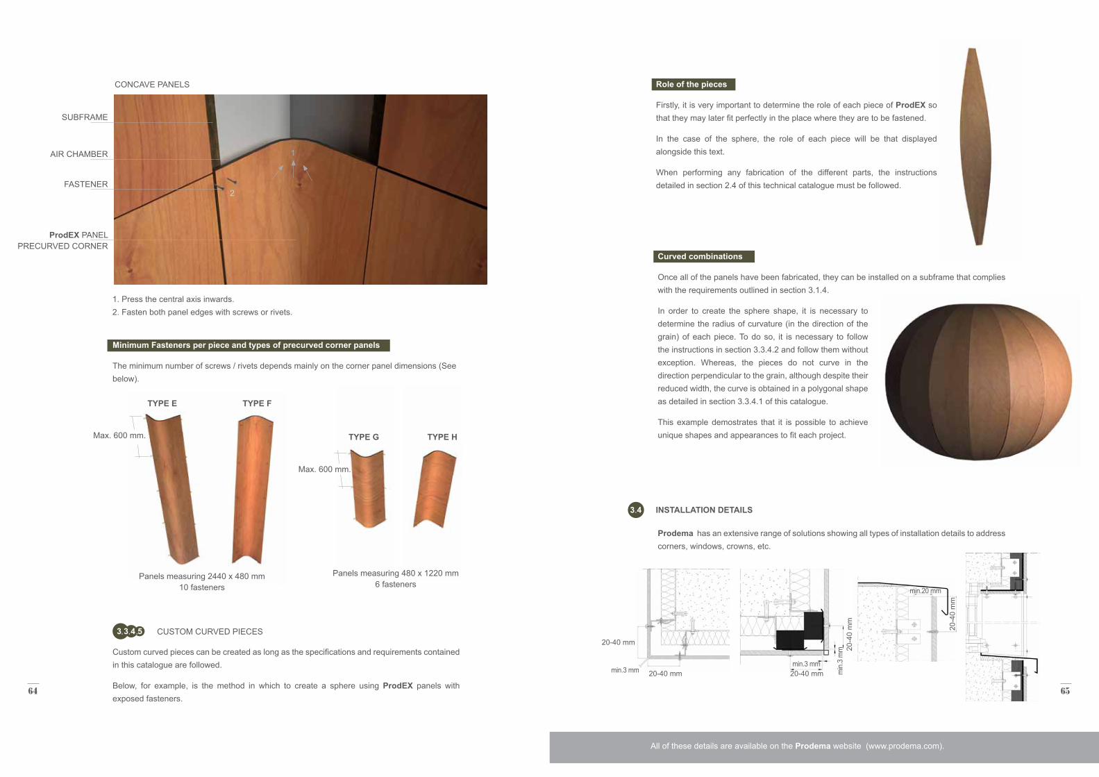
Selection of panels
When seleclting the corner pieces, first consider the desired direction of the grain and whether it is for a convex or concave corner. The options are detailed below.
Installation systems
The installation of these panels, depends on the type of curvature.
2440
250
250
ProdemaNATURAL WOOD BEAUTY
ProdemaNATURAL WOOD BEAUTY
ProdemaNATURAL WOOD BEAUTY
TECHNICAL DATA SHEET
1. INSPECTION
2. DIMENSIONS
3. PHYSICAL PROPERTIES
4. RESISTANCE TO WEATHER
5. SAFETY REQUIREMENTS
2440 1220
250
250
Precurved ProdEX Corner
The precurved corners are offered in convex or concave format.
Size varies according to direction of the grain. = 90º
1220
2
CONVEX PIECES
SUBFRAME
FASTENER
AIR CHAMBER
ProdEX PANEL PRECURVED CORNER
1 CWFT (Classified Without Further Testing): in accordance with EN 438-7 Sect. 4.2.3. Screw or rivet based installation recommended. For other fastening systems consult the Prodema Technical Dept.
2 Format subject to minimum quantities; contact Prodema.
64 65
Max. 600 mm.
Max. 600 mm.
Panels measuring 2440 x 480 mm 10 fasteners
TYPE E TYPE F
TYPE G TYPE H
Panels measuring 480 x 1220 mm 6 fasteners
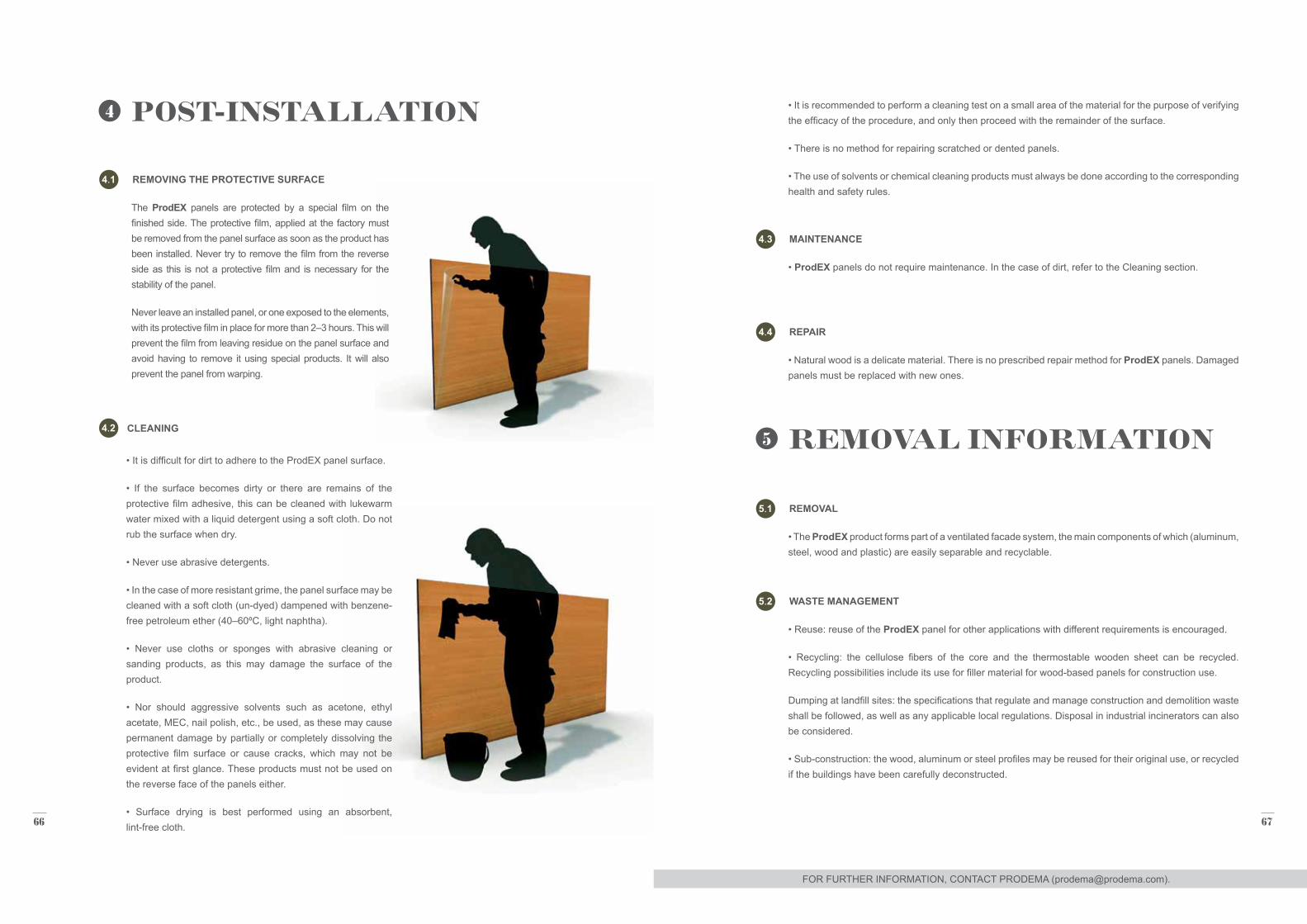
1. Press the central axis inwards. 2. Fasten both panel edges with screws or rivets.
1
CONCAVE PANELS
Minimum Fasteners per piece and types of precurved corner panels
The minimum number of screws / rivets depends mainly on the corner panel dimensions (See below).
SUBFRAME
FASTENER
AIR CHAMBER
ProdEX PANEL PRECURVED CORNER
CUSTOM CURVED PIECES3 3 4 5
Custom curved pieces can be created as long as the specifications and requirements contained in this catalogue are followed.
Below, for example, is the method in which to create a sphere using ProdEX panels with exposed fasteners.
Role of the pieces
Firstly, it is very important to determine the role of each piece of ProdEX so that they may later fit perfectly in the place where they are to be fastened.
In the case of the sphere, the role of each piece will be that displayed alongside this text.
When performing any fabrication of the different parts, the instructions detailed in section 2.4 of this technical catalogue must be followed.
Curved combinations
Once all of the panels have been fabricated, they can be installed on a subframe that complies with the requirements outlined in section 3.1.4.
In order to create the sphere shape, it is necessary to determine the radius of curvature (in the direction of the grain) of each piece. To do so, it is necessary to follow the instructions in section 3.3.4.2 and follow them without exception. Whereas, the pieces do not curve in the direction perpendicular to the grain, although despite their reduced width, the curve is obtained in a polygonal shape as detailed in section 3.3.4.1 of this catalogue.
This example demostrates that it is possible to achieve unique shapes and appearances to fit each project.
Prodema has an extensive range of solutions showing all types of installation details to address corners, windows, crowns, etc.
INSTALLATION DETAILS3 4
All of these details are available on the Prodema website (www.prodema.com).
2
20-40 mm
20-40 mm 20-40 mmmin.3 mmmin.3 mm
min.20 mm
66 67
• It is recommended to perform a cleaning test on a small area of the material for the purpose of verifying the efficacy of the procedure, and only then proceed with the remainder of the surface.
• There is no method for repairing scratched or dented panels.
• The use of solvents or chemical cleaning products must always be done according to the corresponding health and safety rules.
4
5
REMOVING THE PROTECTIVE SURFACE
CLEANING
4 1
4 2
POST-INSTALLATION
REMOVAL INFORMATION
The ProdEX panels are protected by a special film on the finished side. The protective film, applied at the factory must be removed from the panel surface as soon as the product has been installed. Never try to remove the film from the reverse side as this is not a protective film and is necessary for the stability of the panel.
Never leave an installed panel, or one exposed to the elements, with its protective film in place for more than 2–3 hours. This will prevent the film from leaving residue on the panel surface and avoid having to remove it using special products. It will also prevent the panel from warping.
• It is difficult for dirt to adhere to the ProdEX panel surface.
• If the surface becomes dirty or there are remains of the protective film adhesive, this can be cleaned with lukewarm water mixed with a liquid detergent using a soft cloth. Do not rub the surface when dry.
• Never use abrasive detergents.
• In the case of more resistant grime, the panel surface may be cleaned with a soft cloth (un-dyed) dampened with benzene-free petroleum ether (40–60ºC, light naphtha).
• Never use cloths or sponges with abrasive cleaning or sanding products, as this may damage the surface of the product.
• Nor should aggressive solvents such as acetone, ethyl acetate, MEC, nail polish, etc., be used, as these may cause permanent damage by partially or completely dissolving the protective film surface or cause cracks, which may not be evident at first glance. These products must not be used on the reverse face of the panels either.
• Surface drying is best performed using an absorbent, lint-free cloth.
REPAIR
MAINTENANCE
REMOVAL
WASTE MANAGEMENT
4 4
4 3
5 1
5 2
• Natural wood is a delicate material. There is no prescribed repair method for ProdEX panels. Damaged panels must be replaced with new ones.
• ProdEX panels do not require maintenance. In the case of dirt, refer to the Cleaning section.
• The ProdEX product forms part of a ventilated facade system, the main components of which (aluminum, steel, wood and plastic) are easily separable and recyclable.
• Reuse: reuse of the ProdEX panel for other applications with different requirements is encouraged.
• Recycling: the cellulose fibers of the core and the thermostable wooden sheet can be recycled. Recycling possibilities include its use for filler material for wood-based panels for construction use.
Dumping at landfill sites: the specifications that regulate and manage construction and demolition waste shall be followed, as well as any applicable local regulations. Disposal in industrial incinerators can also be considered.
• Sub-construction: the wood, aluminum or steel profiles may be reused for their original use, or recycled if the buildings have been carefully deconstructed.
FOR FURTHER INFORMATION, CONTACT PRODEMA ([email protected]).
68 69
PRGA001EXF
PRGA002EXF
PRGA003EXF
SFS-SX Centering seat
SFS-T25W Adapter
SFS-E 420 Setting tool - Federvision
Accessory to ensure the perpendicularity of the
screw to the panel, as well as its concentric insertion.
Accessory for SX3 and/or TW-S screws with TORX
heads
Accessory for SX3 screws with IRIUS heads
6
GENERAL ELEMENTS FOR THE PRIMARY SUBFRAME
SPECIFIC ELEMENTS FOR THE EXPOSED FASTENING SYSTEM WITH SCREWS OR RIVETS
6 1
6 2
ACCESSORIES
ALUMINUM:
SCREWS
GALVANIZED STEEL
6 1 1
6 2 1
6 1 2
To determine delivery times, minimum quantities, etc., contact Prodema ([email protected]). To determine delivery times, minimum quantities, etc., contact Prodema ([email protected]).
PRAS001BRU
PRSS001GLV
PRAS002BRU
PRSS002GLV
PRAS003BRU
PRSS003GLV
PRAS004BRU
PRSS004GLV
PRAS005BRU(only sold in the USA)
PRAS005AND(only sold in the USA)
PRAS006BRU(only sold in the USA)
PRAS006AND(only sold in the USA)
T profile 60/80 3000 mm long
30 mm Omega profile2500 mm long
T profile 60/40 3000 mm long
L 60/50 profile2500 mm long
L 60 Bracket
L 60 Bracket
L 100 Bracket
L 100 Bracket
Modified J profile 146" (3708 mm) long
Modified J profile 146" (3708 mm) long
Inverted HAT profile 146" (3708 mm) long
Inverted HAT profile 146" (3708 mm) long
Aluminum 6063 / Rough T5
Galvanized steel
Aluminum 6063 / Rough T5
Galvanized steel
Aluminum 6060 / Rough T5
Galvanized steel
Aluminum 6060 / Rough T5
Galvanized steel
Aluminum / Mill
Aluminum / Black anodized
Aluminum / Mill
Aluminum / Black anodized
REFERENCE DESCRIPTION MATERIAL / FINISH
GENERAL ACCESSORIES FOR SCREWS6 2 1 1
REFERENCE DESCRIPTION MATERIAL / FINISH
REFERENCE DESCRIPTION MATERIAL / FINISH
70 71
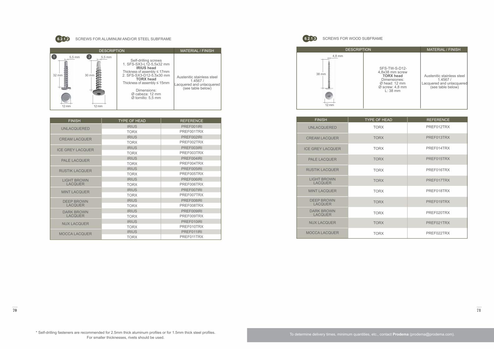
PREF012TRX
PREF014TRX
PREF016TRX
PREF018TRX
PREF020TRX
PREF022TRX
PREF013TRX
PREF015TRX
PREF017TRX
PREF019TRX
PREF021TRX
SFS-TW-S-D12- 4,8x38 mm screw
TORX headDimensiones:
Ø head: 12 mmØ screw: 4,8 mm
L: 38 mm
Austenitic stainless steel 1.4567 /
Lacquered and unlacquered(see table below)
DESCRIPTION
FINISH TYPE OF HEAD REFERENCE
MATERIAL / FINISH
38 mm
12 mm
4,8 mm
TORX
TORX
TORX
TORX
TORX
TORX
TORX
TORX
TORX
TORX
TORX
SCREWS FOR WOOD SUBFRAME6 2 1 3
* Self-drilling fasteners are recommended for 2.5mm thick aluminum profiles or for 1.5mm thick steel profiles. For smaller thicknesses, rivets should be used.
SCREWS FOR ALUMINUM AND/OR STEEL SUBFRAME6 2 1 2
To determine delivery times, minimum quantities, etc., contact Prodema ([email protected]).
Self-drilling screws 1. SFS-SX3-L12-5,5x32 mm
IRIUS headThickness of assembly ≤ 17mm2. SFS-SX3-D12-5,5x30 mm
TORX headThickness of assembly ≤ 15mm
Dimensions: Ø cabeza: 12 mmØ tornillo: 5,5 mm
Austenitic stainless steel 1.4567 /
Lacquered and unlacquered(see table below)
DESCRIPTION MATERIAL / FINISH
32 mm 30 mm
12 mm 12 mm
5,5 mm 5,5 mm1 2
PREF001TRX
PREF003TRX
PREF005TRX
PREF007TRX
PREF009TRX
PREF011TRX
PREF002TRX
PREF004TRX
PREF006TRX
PREF008TRX
PREF010TRX
FINISH TYPE OF HEAD REFERENCE
UNLACQUERED UNLACQUERED
ICE GREY LACQUER ICE GREY LACQUER
RUSTIK LACQUER RUSTIK LACQUER
MINT LACQUER MINT LACQUER
DARK BROWNLACQUER
DARK BROWNLACQUER
MOCCA LACQUER MOCCA LACQUER
CREAM LACQUER CREAM LACQUER
PALE LACQUER PALE LACQUER
LIGHT BROWNLACQUER
LIGHT BROWNLACQUER
DEEP BROWNLACQUER
DEEP BROWNLACQUER
NUX LACQUER NUX LACQUER
IRIUS
IRIUS
IRIUS
IRIUS
IRIUS
IRIUS
IRIUS
IRIUS
IRIUS
IRIUS
IRIUS
PREF001IRI
PREF003IRI
PREF005IRI
PREF007IRI
PREF009IRI
PREF011IRI
PREF002IRI
PREF004IRI
PREF006IRI
PREF008IRI
PREF010IRI
TORX
TORX
TORX
TORX
TORX
TORX
TORX
TORX
TORX
TORX
TORX
72 73
To determine delivery times, minimum quantities, etc., contact Prodema ([email protected]). To determine delivery times, minimum quantities, etc., contact Prodema ([email protected]).
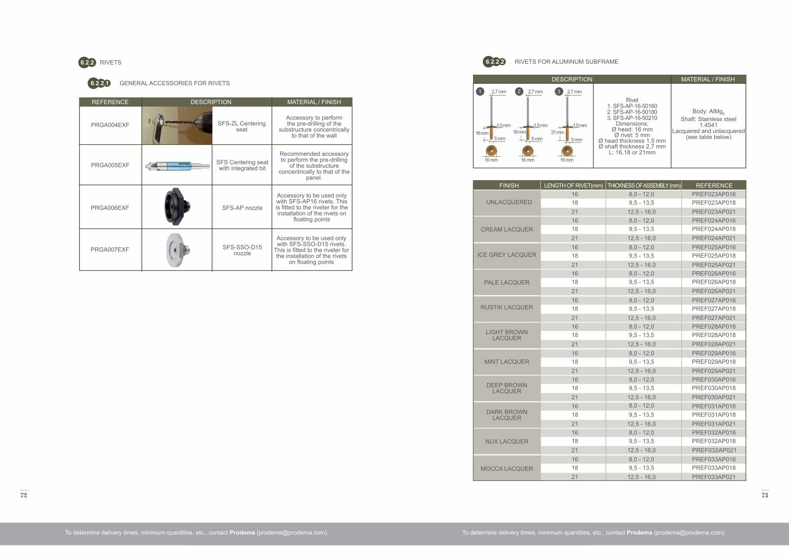
SFS-ZL Centering seat
PRGA004EXF
PRGA005EXF SFS Centering seat with integrated bit
Accessory to perform the pre-drilling of the
substructure concentrically to that of the wall
Recommended accessory to perform the pre-drilling
of the substructure concentrically to that of the
panel.
REFERENCE DESCRIPTION MATERIAL / FINISH
RIVETS6 2 2
GENERAL ACCESSORIES FOR RIVETS6 2 2 1
PRGA006EXF
PRGA007EXF
SFS-AP nozzle
SFS-SSO-D15 nozzle
Accessory to be used only with SFS-AP16 rivets. This is fitted to the riveter for the installation of the rivets on
floating points
Accessory to be used only with SFS-SSO-D15 rivets.
This is fitted to the riveter for the installation of the rivets
on floating points
16 mm 18 mm 21 mm
16 mm 16 mm 16 mm
2,7 mm 2,7 mm 2,7 mm
5 mm 5 mm 5 mm
1,5 mm 1,5 mm 1,5 mm
Rivet1. SFS-AP-16-501602. SFS-AP-16-501803. SFS-AP-16-50210
Dimensions: Ø head: 16 mmØ rivet: 5 mm
Ø head thickness 1,5 mmØ shaft thickness 2,7 mm
L: 16,18 or 21mm
Body: AlMg5
Shaft: Stainless steel 1.4541
Lacquered and unlacquered(see table below)
DESCRIPTION
FINISH THICKNESS OF ASSEMBLY (mm)LENGTH OF RIVET(mm) REFERENCE
MATERIAL / FINISH
UNLACQUERED 18
18
18
18
18
18
18
18
18
18
18
9,5 - 13,5
9,5 - 13,5
9,5 - 13,5
9,5 - 13,5
9,5 - 13,5
9,5 - 13,5
9,5 - 13,5
9,5 - 13,5
9,5 - 13,5
9,5 - 13,5
9,5 - 13,5
PREF023AP018
PREF027AP018
PREF031AP018
PREF024AP018
PREF028AP018
PREF032AP018
PREF025AP018
PREF029AP018
PREF033AP018
PREF026AP018
PREF030AP018
16
16
16
16
16
16
16
16
16
16
16
8,0 - 12,0
8,0 - 12,0
8,0 - 12,0
8,0 - 12,0
8,0 - 12,0
8,0 - 12,0
8,0 - 12,0
8,0 - 12,0
8,0 - 12,0
8,0 - 12,0
8,0 - 12,0
PREF023AP016
PREF027AP016
PREF031AP016
PREF024AP016
PREF028AP016
PREF032AP016
PREF025AP016
PREF029AP016
PREF033AP016
PREF026AP016
PREF030AP016
21
21
21
21
21
21
21
21
21
21
21
12,5 - 16,0
12,5 - 16,0
12,5 - 16,0
12,5 - 16,0
12,5 - 16,0
12,5 - 16,0
12,5 - 16,0
12,5 - 16,0
12,5 - 16,0
12,5 - 16,0
12,5 - 16,0
PREF023AP021
PREF027AP021
PREF031AP021
PREF024AP021
PREF028AP021
PREF032AP021
PREF025AP021
PREF029AP021
PREF033AP021
PREF026AP021
PREF030AP021
RIVETS FOR ALUMINUM SUBFRAME6 2 2 2
1 2 3
ICE GREY LACQUER
RUSTIK LACQUER
MINT LACQUER
DARK BROWNLACQUER
MOCCA LACQUER
CREAM LACQUER
PALE LACQUER
LIGHT BROWNLACQUER
DEEP BROWNLACQUER
NUX LACQUER
74 75
To determine delivery times, minimum quantities, etc., contact Prodema ([email protected]). To determine delivery times, minimum quantities, etc., contact Prodema ([email protected]).
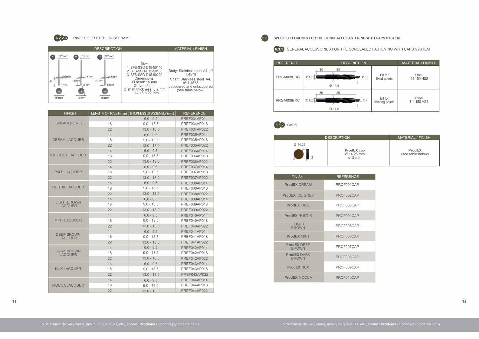
14 mm 18 mm 22 mm
15 mm 15 mm 15 mm
3,2 mm 3,2 mm 3,2 mm
5 mm 5 mm 5 mm
1,5 mm 1,5 mm 1,5 mm
Rivet 1. SFS-SSO-D15-501402. SFS-SSO-D15-501803. SFS-SSO-D15-50220
Dimensions: Ø head: 15 mmØ rivet: 5 mm
Ø shaft thickness: 3,2 mmL: 14,18 o 22 mm
Body: Stainless steel A4, nº 1.4578
Shaft: Stainless steel A4, nº 1.4578
Lacquered and unlacquered(see table below)
DESCRIPCTION
FINISH THICKNESS OF ASSEMBLY (mm)LENGTH OF RIVET(mm) REFERENCE
MATERIAL / FINISH
18
18
18
18
18
18
18
18
18
18
18
9,0 - 13,5
9,0 - 13,5
9,0 - 13,5
9,0 - 13,5
9,0 - 13,5
9,0 - 13,5
9,0 - 13,5
9,0 - 13,5
9,0 - 13,5
9,0 - 13,5
9,0 - 13,5
PREF034AP018
PREF038AP018
PREF042AP018
PREF035AP018
PREF039AP018
PREF043AP018
PREF036AP018
PREF040AP018
PREF044AP018
PREF037AP018
PREF041AP018
14
14
14
14
14
14
14
14
14
14
14
6,0 - 9,5
6,0 - 9,5
6,0 - 9,5
6,0 - 9,5
6,0 - 9,5
6,0 - 9,5
6,0 - 9,5
6,0 - 9,5
6,0 - 9,5
6,0 - 9,5
6,0 - 9,5
PREF034AP014
PREF038AP014
PREF042AP014
PREF035AP014
PREF039AP014
PREF043AP014
PREF036AP014
PREF040AP014
PREF044AP014
PREF037AP014
PREF041AP014
22
22
22
22
22
22
22
22
22
22
22
13,0 - 18,0
13,0 - 18,0
13,0 - 18,0
13,0 - 18,0
13,0 - 18,0
13,0 - 18,0
13,0 - 18,0
13,0 - 18,0
13,0 - 18,0
13,0 - 18,0
13,0 - 18,0
PREF034AP022
PREF038AP022
PREF042AP022
PREF035AP022
PREF039AP022
PREF043AP022
PREF036AP022
PREF040AP022
PREF044AP022
PREF037AP022
PREF041AP022
RIVETS FOR STEEL SUBSFRAME6 2 2 3
1 2 3
UNLACQUERED
ICE GREY LACQUER
RUSTIK LACQUER
MINT LACQUER
DARK BROWNLACQUER
MOCCA LACQUER
CREAM LACQUER
PALE LACQUER
LIGHT BROWNLACQUER
DEEP BROWNLACQUER
NUX LACQUER
REFERENCE DESCRIPTION MATERIAL / FINISH
SPECIFIC ELEMENTS FOR THE CONCEALED FASTENING WITH CAPS SYSTEM6 3
GENERAL ACCESSORIES FOR THE CONCEALED FASTENING WITH CAPS SYSTEM6 3 1
PRGA008BRC
PRGA009BRC
Bit for fixed points
Steel114 150 HSS
Steel114 150 HSS
Bit for floating points
8
8530
Ø 14,5
Ø 10,5 Ø 5,5
8
8530
Ø 14,5
Ø 10,5 Ø 7
CAPS6 3 2
ProdEX capØ 14,25 mm
e: 2 mm
ProdEX(see table below)
DESCRIPTION MATERIAL / FINISH
2
Ø 14,25
FINISH REFERENCE
ProdEX ICE GREY
ProdEX RUSTIK
ProdEX MINT
ProdEX MOCCA
ProdEX CREAM
ProdEX PALE
ProdEX NUX
PRCF002CAP
PRCF004CAP
PRCF006CAP
PRCF008CAP
PRCF010CAP
PRCF001CAP
PRCF003CAP
PRCF005CAP
PRCF007CAP
PRCF009CAP
ProdEX DARK BROWN
ProdEX DEEP BROWN
LIGHT BROWN
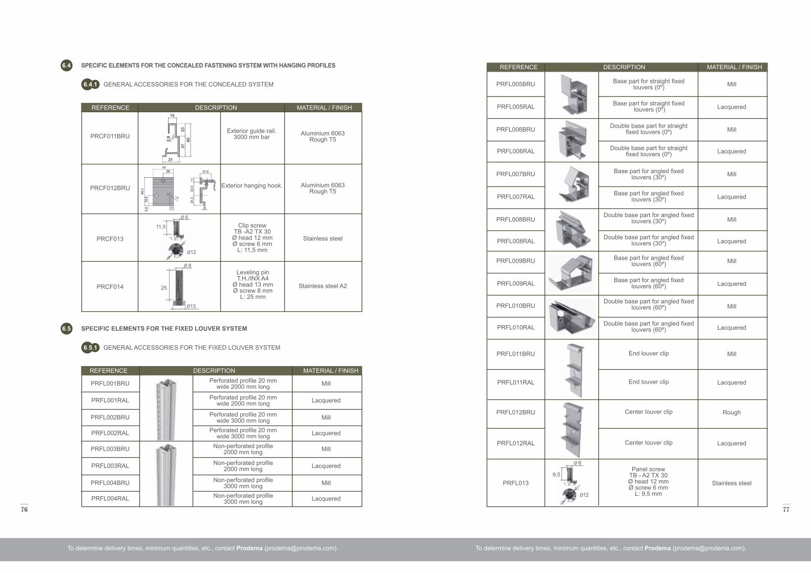
76 77
Perforated profile 20 mm wide 2000 mm long
Non-perforated profile 2000 mm long
Base part for straight fixed louvers (0º)
Double base part for straight fixed louvers (0º)
Double base part for angled fixed louvers (30º)
Double base part for angled fixed louvers (60º)
Base part for angled fixed louvers (30º)
Base part for angled fixed louvers (60º)
Base part for straight fixed louvers (0º)
Double base part for straight fixed louvers (0º)
Double base part for angled fixed louvers (30º)
Double base part for angled fixed louvers (60º)
Base part for angled fixed louvers (30º)
Base part for angled fixed louvers (60º)
End louver clip
Center louver clip
End louver clip
Center louver clip
Perforated profile 20 mm wide 2000 mm long
Non-perforated profile 2000 mm long
Perforated profile 20 mm wide 3000 mm long
Non-perforated profile 3000 mm long
Perforated profile 20 mm wide 3000 mm long
Non-perforated profile 3000 mm long
TORNILLO
PRFL001BRU
PRFL003BRU
PRFL005BRU
PRFL007BRU
PRFL009BRU
PRFL006BRU
PRFL008BRU
PRFL010BRU
PRFL011BRU
PRFL012BRU
PRFL001RAL
PRFL003RAL
PRFL005RAL
PRFL007RAL
PRFL009RAL
PRFL006RAL
PRFL008RAL
PRFL010RAL
PRFL011RAL
PRFL012RAL
PRFL013
PRFL002BRU
PRFL004BRU
PRFL002RAL
PRFL004RAL
Aluminium 6063 Rough T5
Aluminium 6063 Rough T5
Stainless steel
Stainless steel A2
Exterior guide rail.3000 mm bar
Exterior hanging hook.
Mill
Mill
Mill
Mill
Mill
Mill
Mill
Mill
Mill
Rough
Lacquered
Lacquered
Lacquered
Lacquered
Lacquered
Lacquered
Lacquered
Lacquered
Lacquered
Lacquered
Stainless steel
Mill
Mill
Lacquered
Lacquered
To determine delivery times, minimum quantities, etc., contact Prodema ([email protected]). To determine delivery times, minimum quantities, etc., contact Prodema ([email protected]).
SPECIFIC ELEMENTS FOR THE CONCEALED FASTENING SYSTEM WITH HANGING PROFILES
SPECIFIC ELEMENTS FOR THE FIXED LOUVER SYSTEM
6 4
6 5
GENERAL ACCESSORIES FOR THE CONCEALED SYSTEM
GENERAL ACCESSORIES FOR THE FIXED LOUVER SYSTEM
6 4 1
6 5 1
PRCF011BRU
PRCF012BRU
PRCF013
PRCF014
Ø12
9,5
Ø 6
Clip screwTB -A2 TX 30
Ø head 12 mmØ screw 6 mm
L: 11,5 mm
Leveling pinT.H./INX A4
Ø head 13 mmØ screw 8 mm
L: 25 mm
Ø 6
11,5
Ø13
Ø 8
25
Panel screwTB - A2 TX 30 Ø head 12 mmØ screw 6 mm
L: 9,5 mm
Ø12
REFERENCE DESCRIPTION MATERIAL / FINISH
REFERENCE DESCRIPTION MATERIAL / FINISH
REFERENCE DESCRIPTION MATERIAL / FINISH
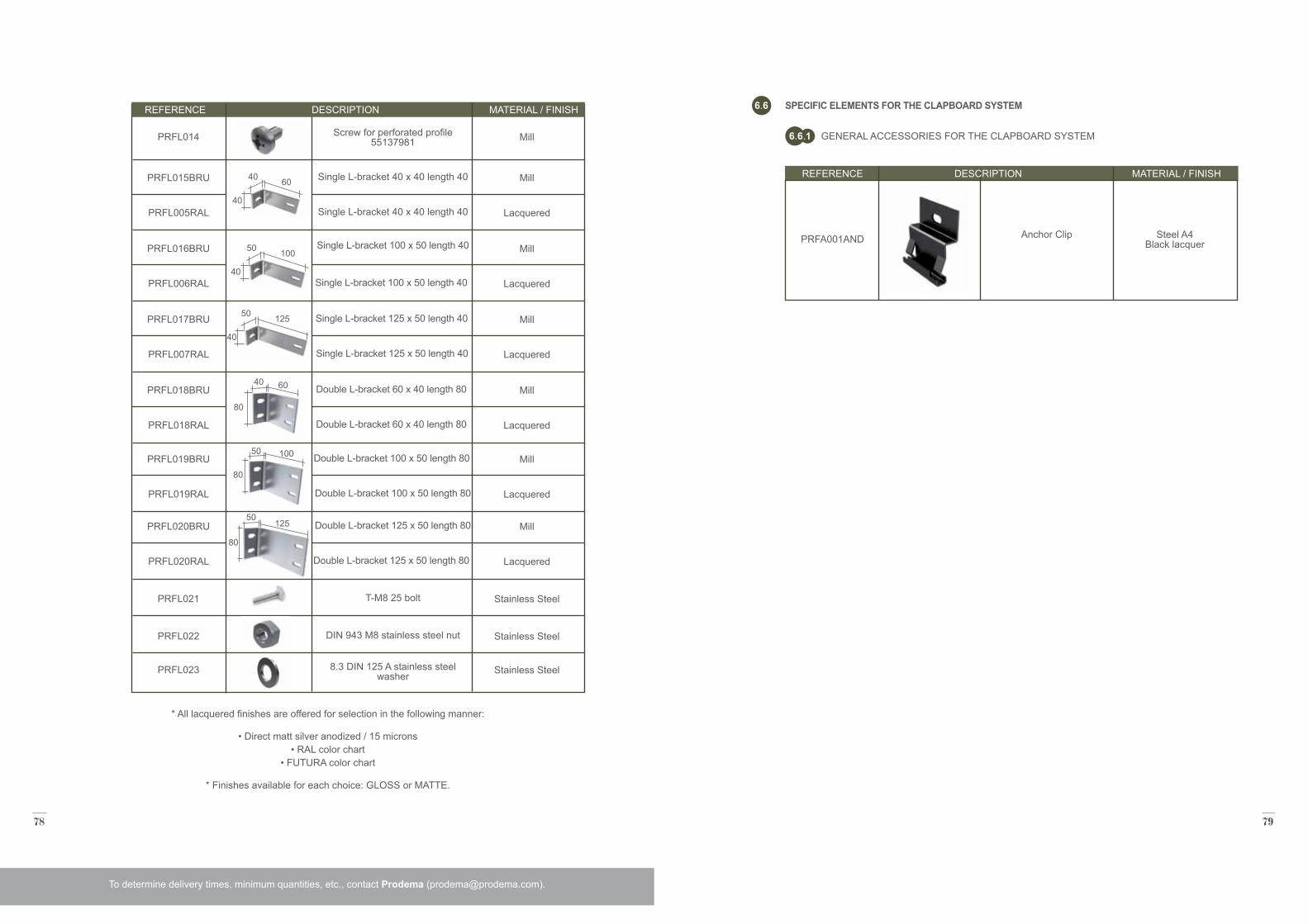
78 79
80
50125
TORNILLO Acero inoxidable
Anchor Clip Steel A4Black lacquer
To determine delivery times, minimum quantities, etc., contact Prodema ([email protected]).
SPECIFIC ELEMENTS FOR THE CLAPBOARD SYSTEM6 6
GENERAL ACCESSORIES FOR THE CLAPBOARD SYSTEM6 6 1
PRFA001AND
Screw for perforated profile55137981
Single L-bracket 40 x 40 length 40
Single L-bracket 100 x 50 length 40
Single L-bracket 125 x 50 length 40
Double L-bracket 60 x 40 length 80
Double L-bracket 100 x 50 length 80
Double L-bracket 125 x 50 length 80
Single L-bracket 40 x 40 length 40
Single L-bracket 100 x 50 length 40
Single L-bracket 125 x 50 length 40
Double L-bracket 60 x 40 length 80
Double L-bracket 100 x 50 length 80
Double L-bracket 125 x 50 length 80
T-M8 25 bolt
DIN 943 M8 stainless steel nut
8.3 DIN 125 A stainless steel washer
PRFL014
PRFL015BRU
PRFL016BRU
PRFL017BRU
PRFL018BRU
PRFL019BRU
PRFL020BRU
PRFL005RAL
PRFL006RAL
PRFL007RAL
PRFL018RAL
PRFL019RAL
PRFL020RAL
PRFL021
PRFL022
PRFL023
Mill
Mill
Mill
Mill
Mill
Mill
Mill
Lacquered
Lacquered
Lacquered
Lacquered
Lacquered
Lacquered
Stainless Steel
Stainless Steel
Stainless Steel
* All lacquered finishes are offered for selection in the following manner:
• Direct matt silver anodized / 15 microns • RAL color chart
• FUTURA color chart
* Finishes available for each choice: GLOSS or MATTE.
40
50 100
80
40 60
80
50 100
40
50 125
40
40 60
REFERENCE DESCRIPTION MATERIAL / FINISH
REFERENCE DESCRIPTION MATERIAL / FINISH
TECHNICALCATALOGUE
2.00
0 E
N
05/2
015
ProdemaNATURAL WOOD BEAUTY
Prodema, S.A. | Barrio San Miguel, s/n, 20.250 Legorreta - Gipuzkoa (Spain) | (t) +34 943 807 130 (f) +34 943 807 130 | C.I.F. A20009247 | [email protected]