technical bulletin Roofline Installation...
8
www.kbp.co.uk Billet Lane, Normanby Enterprise Park, Normanby Road, Scunthorpe, North Lincolnshire, DN15 9YH Tel: (01724) 400440 Fax: (01724) 280241 Email: [email protected] No.7 technical bulletin K22 Fascia & 9mm Vented Soffit Roofline Installation Details K16 Fascia & 9mm Vented Soffit Typical Eaves Details KB16 Fascia & 9mn Vented Soffit 803 Vented Soffit 10mm Air gap 692 Soffit Channel 803 Vented Soffit 10mm Air gap Stainless Steel Polytop Fixings 2 x 65mm @ 600mm Centres Eaves Protector Stainless Steel Polytop Fixings 1 x 40mm @ 600mm Centres 803 Vented Soffit 10mm Air gap Stainless Steel Polytop Fixings 2 x 65mm @ 600mm Centres Stainless Steel Polytop Fixings 2 x 65mm @ 600mm Centres Eaves Protector Eaves Protector This technical bulletin is intended to provide you with a brief overview of the popular products in Kestrel’s Roofline range, where they can be used and the main criteria for installation. Pre-Installation Considerations Preparation: • All access and works to comply with current and relevant Health & Safety and Construction Design Management Regulation recommendations. • Clear work area in-line with best practice before starting work, ensuring safe scaffolding access is available. • Remove first row of roof tiles where necessary. • Remove all existing fascia / soffit materials. • Replace any un-sound / rotten timber or felt and treat rafter ends with preservative. • Maintain air path for roof ventilation. Installation considerations Installation considerations are intended to provide you with need- to-know information for the core processes of product installation. They are not intended as an exhaustive installation guide. The information presented will provide you with a valuable resource when assessing how best to use our products in your selected application. Fascia Fit directly to rafter ends using polytop nails, 2 per fixing centre max 600mm centres - 65mm nails. Austenitic stainless steel (Grade A4 BS6105). Fascia is capable of load bearing in relation to light weight gutters and the first row of roof tiles (Eaves Tiles). Expansion gaps of 5mm per board end must be allowed for during installation. Cover joints and Corners to be secured using low modulus neutral cure silicone. BS5889 Type A. Gutter brackets to be secured directly into the board using stainless steel screws - 10 gauge x 25mm long (parallel thread form). Fascia Installation Details All Kestrel fascia boards 16mm and over are capable of load bearing and may be used in new-build or refurbishment.
Transcript of technical bulletin Roofline Installation...

www.kbp.co.ukBillet Lane, Normanby Enterprise Park, Normanby Road, Scunthorpe, North Lincolnshire, DN15 9YH
Tel: (01724) 400440 Fax: (01724) 280241 Email: [email protected]
No.7technical bulletin
FM 506475
K22 Fascia & 9mm Vented Soffit
Roofline Installation Details
K16 Fascia & 9mm Vented SoffitTypical Eaves Details
KB16 Fascia & 9mn Vented Soffit
803 Vented Soffit
10mm Air gap 692 Soffit Channel
803 Vented Soffit
10mm Air gap
Stainless Steel Polytop Fixings
2 x 65mm @ 600mm Centres
Eaves Protector
Stainless Steel Polytop Fixings
1 x 40mm @ 600mm Centres
803 Vented Soffit
10mm Air gap
Stainless Steel Polytop Fixings
2 x 65mm @ 600mm Centres
Stainless Steel Polytop Fixings
2 x 65mm @ 600mm Centres
Eaves Protector
Eaves Protector
This technical bulletin is intended to provide you with a brief overview of the popular products in Kestrel’s Roofline range, where they can be used and the main criteria for installation.
Pre-Installation ConsiderationsPreparation:• All access and works to comply with current and relevant Health & Safety and Construction Design Management Regulation recommendations.• Clear work area in-line with best practice before starting work, ensuring safe scaffolding access is available.• Remove first row of roof tiles where necessary.• Remove all existing fascia / soffit materials.• Replace any un-sound / rotten timber or felt and treat rafter ends with preservative.• Maintain air path for roof ventilation.
Installation considerationsInstallation considerations are intended to provide you with need-to-know information for the core processes of product installation.
They are not intended as an exhaustive installation guide. The information presented will provide you with a valuable resource when assessing how best to use our products in your selected application.
FasciaFit directly to rafter ends using polytop nails, 2 per fixing centre max 600mm centres - 65mm nails. Austenitic stainless steel (Grade A4 BS6105). Fascia is capable of load bearing in relation to light weight gutters and the first row of roof tiles (Eaves Tiles).Expansion gaps of 5mm per board end must be allowed for during installation.Cover joints and Corners to be secured using low modulus neutral cure silicone. BS5889 Type A. Gutter brackets to be secured directly into the board using stainless steel screws - 10 gauge x 25mm long (parallel thread form).
Fascia Installation Details
All Kestrel fascia boards 16mm and over are capable of load bearing and may be used in new-build or refurbishment.

www.kbp.co.ukBillet Lane, Normanby Enterprise Park, Normanby Road, Scunthorpe, North Lincolnshire, DN15 9YH
Tel: (01724) 400440 Fax: (01724) 280241 Email: [email protected]
technical bulletin No.7
870/150 150mm Vented
Shiplap Cladding
Stainless Steel Polytop Fixings
2 x 65mm @ 600mm Centres
Eaves Protector
670/150 150mm
Shiplap Cladding681 Two
Part Trim
Framing to
secure soffit
Soffit over brick
to timber frame
K16 Fascia
Secure to rafterends with polynails2 x 65mm @ 600mm Centres
903 range 25mm vented soffit to
ventilate 50mm air space
AIR PATH
018 Fascia & 150mm Shiplap Cladding - Vented
K16 & 803 Timber Frame Detail
Flat Roof Detail
Sealant
Stainless Steel Polytop Fixings
2 x 65mm @ 600mm Centres
Eaves Protector
Fascia Installation DetailsTongue and Groove CladdingShiplap and Open-V cladding planks may also beused as soffit and are available in vented and nonvented versions. Vented cladding planks have a12.5mm air gap which permit 25mm continuousventilation to be achieved via the use of two rows ofvented product. Cladding planks are secured using30mm cladding pins.
NB: When using 018 as a bargeboard the boxend piece will need to be packed out toprevent the Ogee form of the bargeboardstanding proud of the box end piece.
Timber FrameWhen fitting to timber frame project, be aware the soffitneeds to be large enough to carry over the top of thebrickwork liner, back to the timber frame. Soffit widths should not exceed 300mm without additional support.
Flat Roof InstallationWhen fitting to a flat roof area, consideration must begiven to allow adequate ventilation above the insulationin order to comply with building regulations. See page11 for a full explanation of ventilation requirements.
NB: Joints for K22, K16, KB16 & K605 areavailable in 600mm lengths in addition toshorter standard lengths.
www.kbp.co.ukBillet Lane, Normanby Enterprise Park, Normanby Road, Scunthorpe, North Lincolnshire, DN15 9YH
Tel: (01724) 400440 Fax: (01724) 280241 Email: [email protected]
technical bulletin No.7
40mm Polytop
pin
Fit directly to gable ladder
Plain soffit board to
verge
Bargeboard Installation Details
Stainless Steel Polytop Fixings2 x 65mm @ 600mm Centres for 16mm barge
Fit directly to gable rafter
No soffit used barge tight to brickwork
Fit directly to gable ladder
Stainless Steel Polytop Fixings2 x 50mm @ 600mm Centres for 8mm barge
K16 - 16mm Bargeboard & Plain Soffit
Typical Verge DetailsBargeboardK16 16mm bargeboard should be installedusing 65mm Polytop nails 2 per fixing centreat maximum 600mm centres. Austeniticstainless steel (grade A4 BS6105).
605 9mm bargeboard should be installed using50mm Polytop nails 2 per fixing centre atmaximum 600mm centres. Austeniticstainless steel (grade A4 BS6105).
Boards less than 16mm thick boardsare required to be fully supportedalong their length.
K-Wave and K-Crest being 16mm thickshould be installed using 65mm Polytopnails 2 per fixing centre at maximum 600mmcentres.
The joint of bargeboards meeting at a ridgeshould be covered using a cover joint orfeature finial and secured using LowModulus Neutral Cure Silicone
Complementary RangesThe K16 and 605 are complememtaryranges being the same external shape.This allows the 9mm barge to be used inconjuntion with the 16mm fascia for a morecost effective solution.
The K22 and KB16 are also complememtaryranges being the same external shape.
This allows the 16mm a barge, to be used in conjuntion with the 22mm fascia, to be a more cost effective solution.
NB: KB16 barge can be run into a K22 box end piece to create a stepped box end feature.
Stainless Steel Polytop Fixings2 x 50mm @ 600mm Centres for 9mm barge
Sealant
605 - 9mm Bargeboard & No Soffit
008 - 8mm Bargeboard to Timber Frame

www.kbp.co.ukBillet Lane, Normanby Enterprise Park, Normanby Road, Scunthorpe, North Lincolnshire, DN15 9YH
Tel: (01724) 400440 Fax: (01724) 280241 Email: [email protected]
technical bulletin No.7
*Unexploded view of method 1
*Exploded view of method 1
Box End Installations
External CornerJoint
Bargeboard
Non-VentedSoffit
Box EndPiece
VentedSoffit
FasciaBoard
External CornerJoint
H SectionJoint Trim
Method 1
Method 2
SmallCornerJoint
LargeCornerJoint
CutLarge Corner
SmallCornerJoint
FasciaJoint
SmallCornerJoint
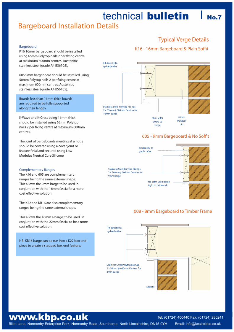
Boxed EndsTo provide a neat and weathertight area at the point where Fascia and Bargeboard meet, it is necessary to construct a box end.
A box end piece is cut from wide Bargeboard material (nominally 405mm) to suit the roof pitch and overhang requirement. When using 605 bargeboard large box end details may be obtained by using the extra wide product of 600mm width.
The soffit forming the base of the box end must match the eaves soffit and is mitred at the joint, using 691 H-section as a jointing trim.
Box ends are supported using a preservative treated timber framework.
Boxed End MethodsThe jointing of the bargeboard into the box end piece can be achieved in two ways
Method 1The bargeboard is cut plumb directly above the back edge of the box. A corner joint with a piece of one face removed is then used to cover the back corner and bargeboard/box end piece joint.
Method 2The bargeboard is cut perpendicular to its length; the angled joint between the boards being covered by a cover joint with its return leg removed. The bottom edge of the cover joint is then cut to mate with the top edge of the corner joint used to cover the back corner of the box end.

www.kbp.co.ukBillet Lane, Normanby Enterprise Park, Normanby Road, Scunthorpe, North Lincolnshire, DN15 9YH
Tel: (01724) 400440 Fax: (01724) 280241 Email: [email protected]
technical bulletin No.7Soffit Installation Details
SoffitKestrel 9mm soffit boards are available in non-vented versions for use as verge soffit or as eaves soffit when other forms of eaves ventilation are to be used. They are also available in ventilated form and can contribute towards providing the necessary roof space ventilation.Soffit is secured at maximum 600mm centres to timber using 40mm Polytop pins, alternatively a wall side fix may be achieved using 692 Soffit Channel.In properties where the outer skin of brickwork is level with the bottom of the fascia board soffit groove, the soffit may be extended over the brickwork and clamped using timber battens secured to the rafter sides.Soffit widths should not exceed 300mm without additional support.A H-section trim 691 is used to join soffit boards.
Allow 5mm expansion gap per board end
concealed by 691 soffit joint trim
Stainless Steel Polytop Fixings1 x 40mm @ 600mm Centres
25 25
25 25
10
5
10 10
5*
5
50
Roofline VentilationCold RoofsThe requirement to ventilate the roof space of a building, to
protect the building and people who use it, from the harmful effects caused by condensation is covered by ‘The Building Regulations 2000.’ Guidance on the provision of adequate ventilation is given in Approved Document C2 Resistance to Moisture (2004 edition) and detailed in BS5250: 2002 Code of practice for control of condensation in buildings.Kestrel provides a comprehensive range of products designed to comply with the requirements of these regulations. Kestrel 9mm soffit boards are available in non-vented versions for use as verge soffit or as eaves soffit when other forms of eaves ventilation are to be used.They are also available in ventilated form and will contribute towards providing the necessary roof space ventilation.These pre-ventilated soffits are available in 10mm air gap up to 600mm wide and 25mm air gap up to 450mm wide.All soffits are covered by Kestrel’s British Board of Agrement Certificate No. 95/3117.
Provision of VentilationThe illustrations reflect the basic ventilation requirements normally applicable. For additional information please refer to the current Building Regulations and appropriate British Standards.
Over 15 ° Pitch * For pitches over 35 ° or spans in excess of 10m
Over 15 ° Pitch Pitches of 15 ° or less require 25mm at eaves
15 ° Pitch or under
All Pitches
803 903
Warm Roofs
Provision of Ventilation
10mm Air Gap 25mm Air Gap
Dimensions in millimetres.

www.kbp.co.ukBillet Lane, Normanby Enterprise Park, Normanby Road, Scunthorpe, North Lincolnshire, DN15 9YH
Tel: (01724) 400440 Fax: (01724) 280241 Email: [email protected]
technical bulletin No.7
K712 Over Fascia Ventilation Strips
2.2mm x 50mm S/Steel annular ring shank fixing pin
@ max 200mm centers
30mm Stainless Steel Pins@ max 600mm Centres
Eaves Protector
Sarking Felt30mm Galvanised Clout Nail
@ each rafter centre
125mmmin. overlap
AIR FLOW
Bird Guard
Roofline Ventilation
K708 Eaves Protector
125mmmin. overlap
K711 Over Fascia Ventilator & Eaves Protector
AIR FLOW
603 Plain Soffit
K712 10mm ventilation strip
Sarking Felt30mm Galvanised Clout Nail
@ each rafter centre
2.2mm x 50mm S/Steel annular ring shank fixing pin.
K712/025 25mm ventilation strip
Ventilation and Eaves ProctectionEaves ProtectionThe Kestrel Eaves Protector K708 has been designed toprovide a long-term solution to the problems associatedwith eaves decay under the roof, including the degradation of sarking felt and the secondary rotting ofrafter timbers and other roof structures.
Available in 1.5m, 2.55m or 4.95m lengths the Kestreleaves protection profile consists of a durable blackpigmented PVC-U profile located between the roof tilesand the PVC-UE fascia system.
Whether used on refurbishment projects or in new-buildinstallations, the traditional sarking felt finishes before thefascia and is lapped over the eaves protector. Therefore itis not exposed to the elements and is not subject todecay.
Ventilation and Eaves ProtectionA further enhancement of the idea of the eaves protectorcomes in the form of K711 an eaves protector combinedwith over fascia ventilation and bird comb. The ventilationof the roof void at eaves level is provided by an upstandon the underside of the eaves protector which sits on thetop edge of the fascia board. The K711 product provides ventilation equivalent to a 10mm continuous slot.This product is also available as K711/25 to provide ventilation equivalent to a 25mm continuous slot.
The provision of an integral bird comb provides an effective barrier against bird infiltration into the roof void when using profiled roof tiles. If flat slate tiles are to be used the comb is readily removed.
The durability and rigidity of the eaves protectors and theload bearing features of Kestrel fascia boards are suchthat no tilting fillet is needed.
Eaves VentilationA simple means of providing ventilation over the fascia is also available in the form of Kestrel K712 over fascia ventilation strips.
The K712 product provides ventilation equivalent to a 10mm continuous slot.
This product is also available as K712/025 to provide ventilation equivalent to a 25mm continuous slot.
As with the K711, this product is designed to sit directly on top of the fascia board. Fix with 2.2mm x 50mm stainless steel annular ring shank fixing pin at every fixing centre.

www.kbp.co.ukBillet Lane, Normanby Enterprise Park, Normanby Road, Scunthorpe, North Lincolnshire, DN15 9YH
Tel: (01724) 400440 Fax: (01724) 280241 Email: [email protected]
technical bulletin No.7
Corner & Fascia JointingExpansion Gaps
to be 5mm
per Board End
Min5mm
Min5mm
Corner joint Large Corner joint
Fascia jointcut to suit
Using standard cornerjoint cut to suit
Fascia jointcut to suitapex joint
Fascia jointcut to suitbarge joint
Fascia joint Fascia joint
Barge boardcut to suit
Method 3 Method 4
Min5mm
Overall min10mm
Corner Joint - Plan ViewNotch leg of one
side fascia atcorner
Min5mm
Min5mm
Typical Jointing Details
Min10mm
Leave 5mm expansion gap per board end at junction
Standard fascia joint
Apex Joint
Apex JointApex joints are made utilising a standard fascia joint from the main fascia range cut to suit. e.g. for the K16 range item 649/300.Alternatively, a decorative finial (K714) can be used to give a more aesthetically pleasing finish.
Running Gables / In-Line PikesWhere fascia meets barge along a running gable, it is important that the same range of fascia and bargeboard are used. This will prevent a step being created.Four typical methods are detailed below. The method used will be determined by the roof pitch or configuration.
Construction of In-Line Pike JunctionsIn-line pike junctions can be created using standard joints from the relevant ranges. In-line boxends can also be created using the same construction methods as shown previously on page 4.
Joints and bargeboards will need cutting to suit.
Fascia and bardgeboard material will need to be the same type.
This type of detail is often used to a side gable where the gable meets a roof projection.
Method 1 Method 2
Jointing of Fascia & BargeboardAll Kestrel fascia board ranges have a series of specifically designed accessories to complement the size and shape of the fascia board.These include some of the following:
• Extra Large Corner Joints (Typically 600mm for Box ends)• Standard Corner Joints• Fascia Joints• Internal Corner Joints• End Caps
All joints should be secured using Low ModulusNeutral Cure Silicone.
In-Line Box End Options

www.kbp.co.ukBillet Lane, Normanby Enterprise Park, Normanby Road, Scunthorpe, North Lincolnshire, DN15 9YH
Tel: (01724) 400440 Fax: (01724) 280241 Email: [email protected]
technical bulletin No.7
FM 506475
Roofline Installation Guide - Foiled
Mahogany Blackgrain Sherwood Rosewood
Min16mm
Expansion Gapto be 8mm
per Board End
Foiled Fascia Joint Installation Details
Foiled Soffit Joint Installation Details
Min8mm
Min8mm
Overall min16mm
Expansion Gapto be 8mm
per Board End
Working with Woodgrain products requires some slightly modified procedures and installation processes.
Overall, woodgrain products are as easy and convenient to fit and use as most other products in the Kestrel range.
However, with a little extra knowledge and care at the preparation stage, you can save yourself potential difficulties later on.
Kestrel’s Woodgrain foiled profiles have been extensivelytested to ensure long term weatherability and areguaranteed for use both internally and externally for a periodof 10 years. However, non-white systems have a differentpotential for heat absorption, with resultant risk of excessiveexpansion and contraction.
In particular, with a Woodgrain foiled coating, this heat absorption can be significant, with potentially detrimental effects on long term installation. Special consideration needs to be given when installing Woodgrain products to minimise the amount of heat build up and provide for greater amounts of expansion.
The following additional fixing details must be followed wheninstalling Woodgrain products:
Fascias/Bargeboard
1. Increase expansion gap from 5mm for white to 8mm.
2. All installations to take place at ambient temperatures -between 5°C and 25°C.
3. All pre-installed products to be kept away from directsunlight, preferably indoors, at all times.
4. All joints to be made with Woodgrain corners and buttjoints.