
TECHNICAL BULLETIN #52 Briefs/bulletin 52... · TECHNICAL BULLETIN #52 Rondo Internal Express Joint...
4
Rondo Building Services Pty Limited ABN 69 000 289 207 CUSTOMER SERVICE HOTLINE 1300-36-RONDO (1300-36-7663) www.rondo.com.au TECHNICAL BULLETIN #52 Introducing Rondo’s new internal Express Joint Wall and Ceiling System AUSTRALIA • NEW ZEALAND • MALAYSIA • MIDDLE EAST • INDOCHINA KEY-LOCK ® Express Joint Wall System Installation KEY-LOCK ® Express Joint Ceiling System Installation June 2010
Transcript of TECHNICAL BULLETIN #52 Briefs/bulletin 52... · TECHNICAL BULLETIN #52 Rondo Internal Express Joint...
Rondo Building Services Pty Limited ABN 69 000 289 207
CUSTOMER SERVICE HOTLINE1300-36-RONDO (1300-36-7663)
www.rondo.com.au
TECHNICAL BULLETIN #52Introducing Rondo’s new internal Express Joint Wall and Ceiling System
A U S T R A L I A • N E W Z E A L A N D • M A L AY S I A • M I D D L E E A S T • I N D O C H I N A
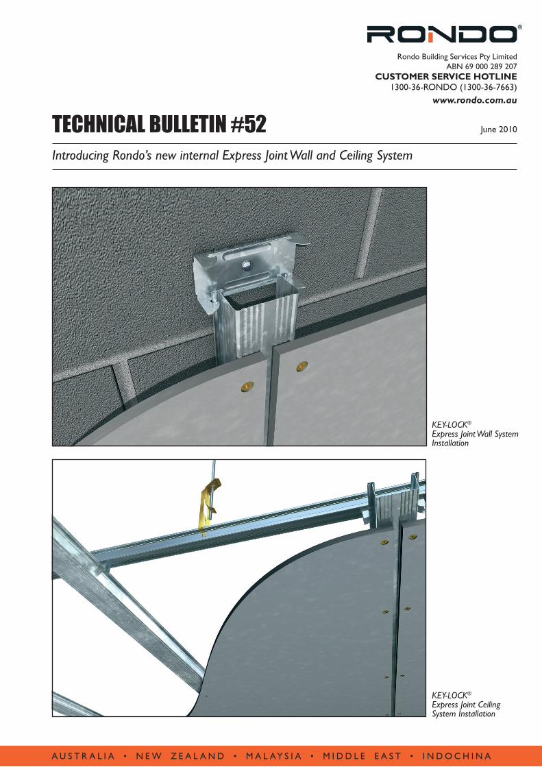
KEY-LOCK® Express Joint Wall System Installation
KEY-LOCK® Express Joint Ceiling System Installation
June 2010

Rondo’s new 155 Express Joint Furring Channel, together with three complementary clips, join Rondo’s existing KEY-LOCK® range to create a 10mm-wide architectural feature which achieves a stylish finish to both wall and ceiling for internal applications.
The 10mm-wide central strip on the Furring Channel works as a practical guide when spacing the sheets, whilst the overall width of the product provides the appropriate fixing margin for the board. The Rondo head ensures safer handling and positive secure location in the appropriate clip, without requiring any mechanical fixing.
Designed for interior installations, the Express Joint Wall and Ceiling System can be used externally, however advice should be sought from Rondo to determine appropriate fixing information and advice on potentially corrosive environments.
The introduction of Rondo’s Express Joint Wall and Ceiling System includes the release of three new clips specifically designed to accommodate the 155 Furring Channel in wall and ceiling applications.
• The 155 Express Joint Furring Channel can be fixed to a masonry wall with the 157 Direct Fix Clip (see Figures 1&5).
• The 159 Joiner allows the 155 Furring Channel to be attached to KEY-LOCK® Top Cross Rail primary suspension members for use in ceiling situations (see Figure 2).
• The 156 Direct Fix Clip is able to fix the 155 Furring Channel to steel purlins or timber joists in ceiling applications as well as to steelgirts or timber stud work in walls (see Figures 3&4).
The KEY-LOCK® Express Joint Wall and Ceiling System is manufactured in Australia from G2 Z275 Galvabond steel and complies with all relevant standards.
For more information on the KEY-LOCK® Express Joint Wall and Ceiling System, visit www.rondo.com.au or contact one of our Technical Representatives at your state Rondo Sales office on 1300 36 7663.
Rondo Internal Express Joint Wall and Ceiling System TECHNICAL BULLETIN #52
2
FIGURE 1
FIGURE 2
FIGURE 3
FIGURE 4
TECHNICAL BULLETIN #52 Rondo Internal Express Joint Wall and Ceiling System
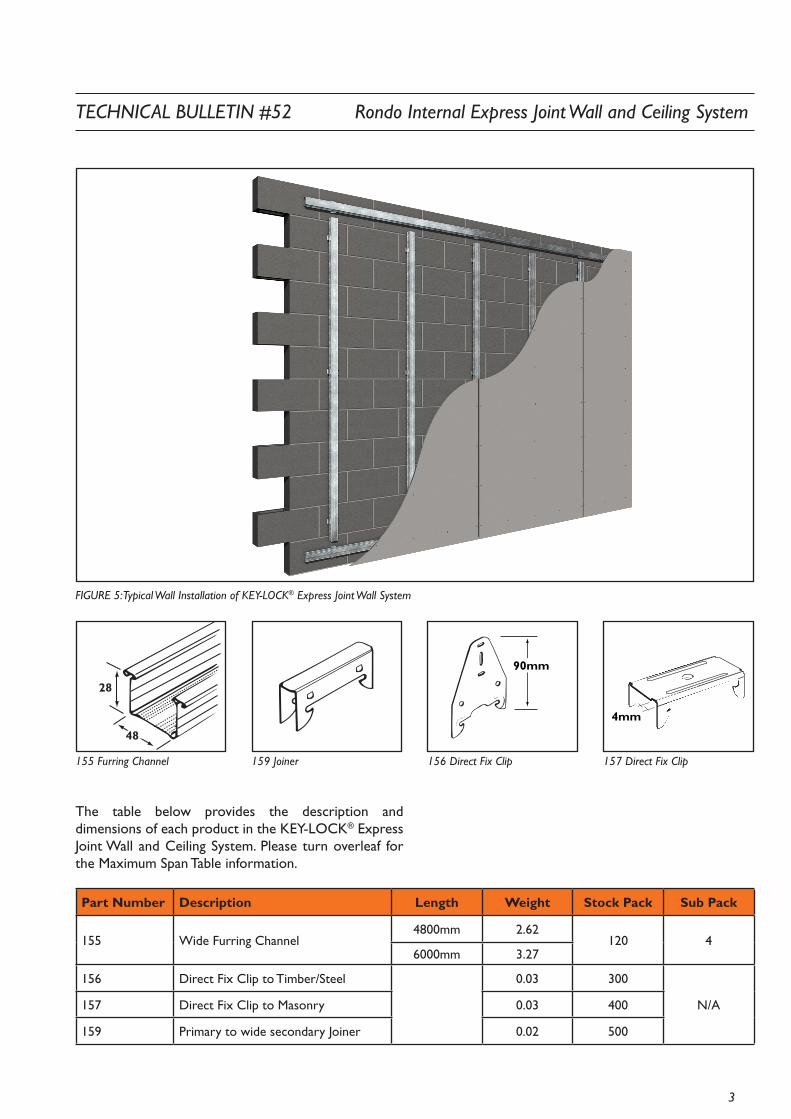
FIGURE 5: Typical Wall Installation of KEY-LOCK® Express Joint Wall System
155 Furring Channel 159 Joiner 156 Direct Fix Clip 157 Direct Fix Clip
Part Number Description Length Weight Stock Pack Sub Pack
155 Wide Furring Channel4800mm 2.62
120 46000mm 3.27
156 Direct Fix Clip to Timber/Steel 0.03 300
N/A157 Direct Fix Clip to Masonry 0.03 400
159 Primary to wide secondary Joiner 0.02 500
The table below provides the description and dimensions of each product in the KEY-LOCK® Express Joint Wall and Ceiling System. Please turn overleaf for the Maximum Span Table information.
3
28
48
90mm
4mm
TECHNICAL BULLETIN #52 June 2010
Introducing Rondo’s new internal Express Joint Wall and Ceiling System
A U S T R A L I A • N E W Z E A L A N D • M A L AY S I A • M I D D L E E A S T • I N D O C H I N A
For more information on the KEY-LOCK® Express Joint Wall and Ceiling System, visit www.rondo.com.au or contact one of our Technical Representatives at your state Rondo Sales office on 1300 36 7663.
RONDO is a registered trademark of Rondo Building Services Pty Ltd. ABN 69 000 289 207.
www.rondo.com.au
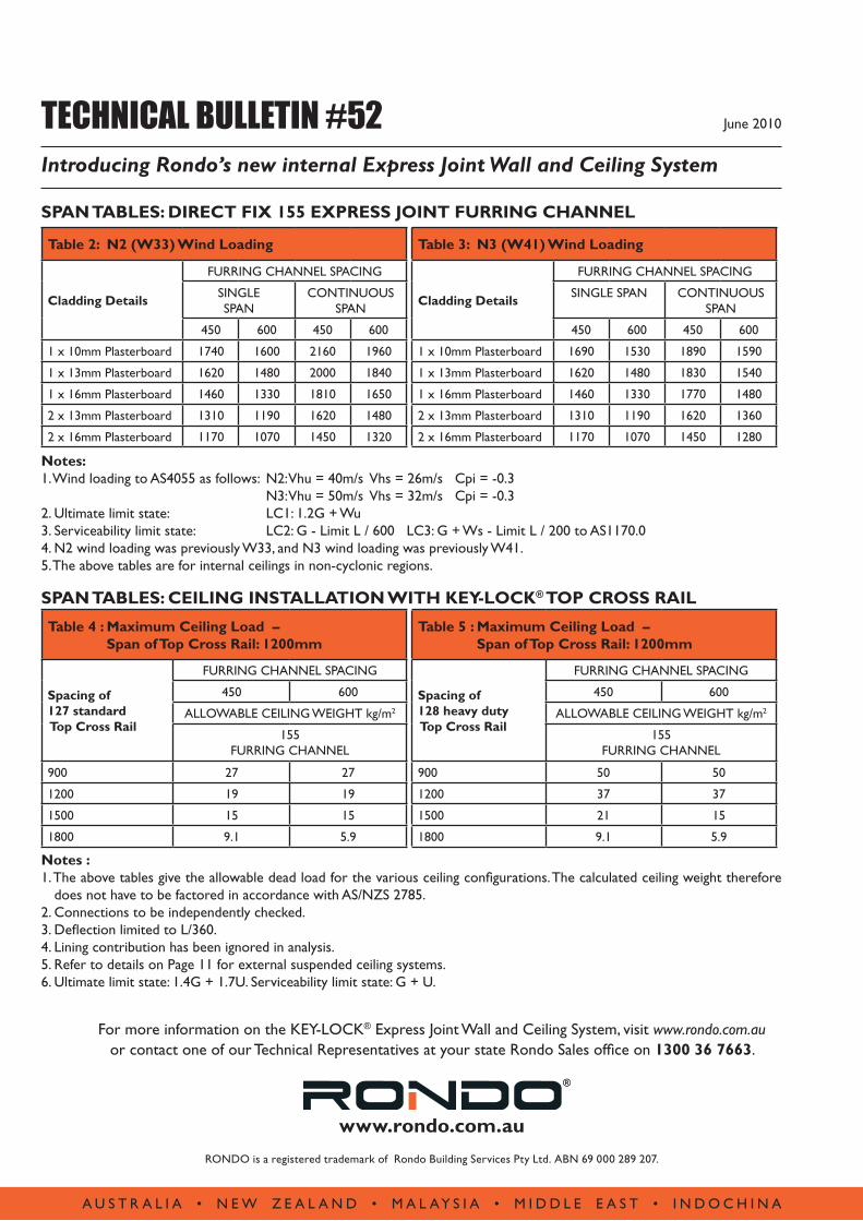
Table 2: N2 (W33) Wind Loading
Cladding Details
FURRING CHANNEL SPACING
SINGLE SPAN
CONTINUOUS SPAN
450 600 450 600
1 x 10mm Plasterboard 1740 1600 2160 1960
1 x 13mm Plasterboard 1620 1480 2000 1840
1 x 16mm Plasterboard 1460 1330 1810 1650
2 x 13mm Plasterboard 1310 1190 1620 1480
2 x 16mm Plasterboard 1170 1070 1450 1320
Table 4 : Maximum Ceiling Load – Span of Top Cross Rail: 1200mm
Spacing of 127 standard Top Cross Rail
FURRING CHANNEL SPACING
450 600
ALLOWABLE CEILING WEIGHT kg/m2
155 FURRING CHANNEL
900 27 27
1200 19 19
1500 15 15
1800 9.1 5.9
Table 5 : Maximum Ceiling Load – Span of Top Cross Rail: 1200mm
Spacing of 128 heavy duty Top Cross Rail
FURRING CHANNEL SPACING
450 600
ALLOWABLE CEILING WEIGHT kg/m2
155 FURRING CHANNEL
900 50 50
1200 37 37
1500 21 15
1800 9.1 5.9
Table 3: N3 (W41) Wind Loading
Cladding Details
FURRING CHANNEL SPACING
SINGLE SPAN CONTINUOUS SPAN
450 600 450 600
1 x 10mm Plasterboard 1690 1530 1890 1590
1 x 13mm Plasterboard 1620 1480 1830 1540
1 x 16mm Plasterboard 1460 1330 1770 1480
2 x 13mm Plasterboard 1310 1190 1620 1360
2 x 16mm Plasterboard 1170 1070 1450 1280
Notes: 1. Wind loading to AS4055 as follows: N2: Vhu = 40m/s Vhs = 26m/s Cpi = -0.3 N3: Vhu = 50m/s Vhs = 32m/s Cpi = -0.3 2. Ultimate limit state: LC1: 1.2G + Wu 3. Serviceability limit state: LC2: G - Limit L / 600 LC3: G + Ws - Limit L / 200 to AS1170.0 4. N2 wind loading was previously W33, and N3 wind loading was previously W41. 5. The above tables are for internal ceilings in non-cyclonic regions.
Notes : 1. The above tables give the allowable dead load for the various ceiling configurations. The calculated ceiling weight therefore
does not have to be factored in accordance with AS/NZS 2785.2. Connections to be independently checked.3. Deflection limited to L/360.4. Lining contribution has been ignored in analysis.5. Refer to details on Page 11 for external suspended ceiling systems.6. Ultimate limit state: 1.4G + 1.7U. Serviceability limit state: G + U.
SPAN TABLES: DIRECT FIX 155 EXPRESS JOINT FURRING CHANNEL
SPAN TABLES: CEILING INSTALLATION WITH KEY-LOCK® TOP CROSS RAIL


