Technical Brochure LTG Air Distribution · Technical Brochure LTG Air Distribution The Innovation...
16
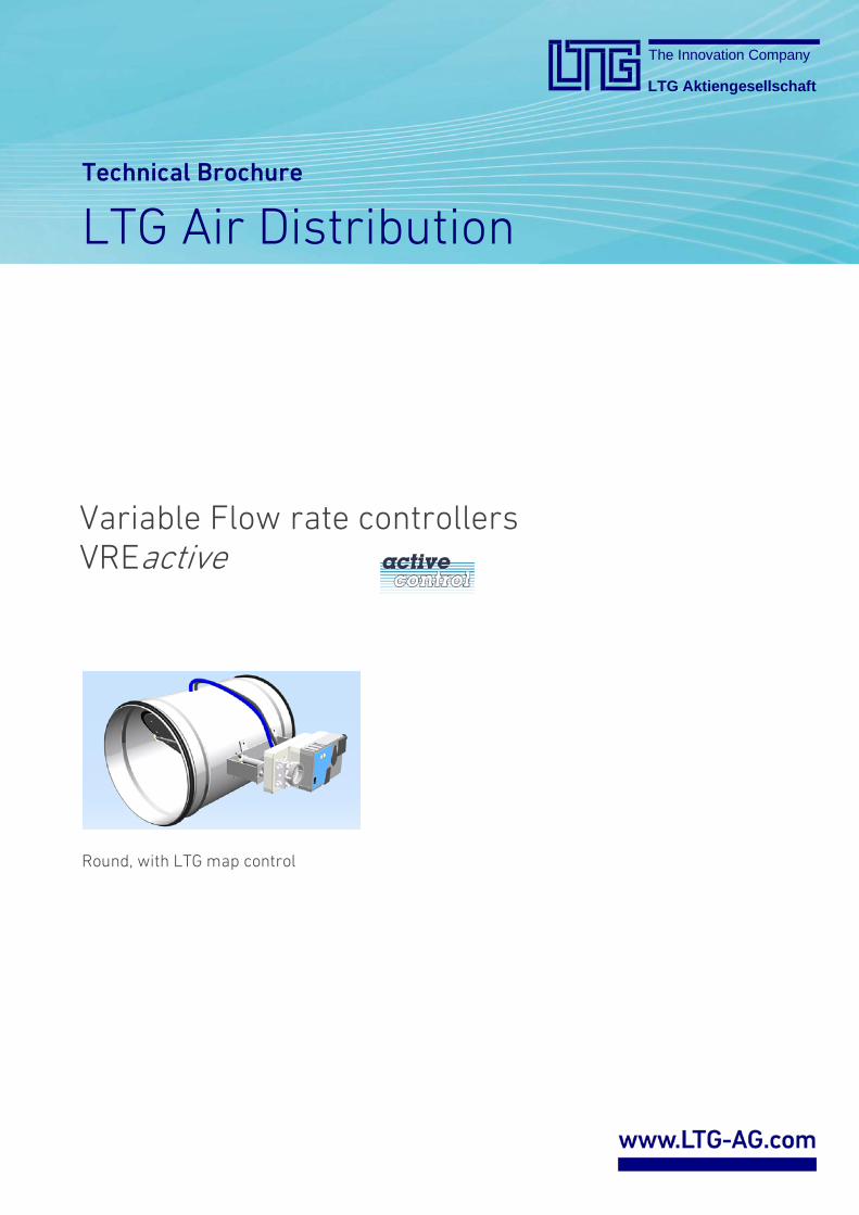
Technical Brochure LTG Air Distribution The Innovation Company LTG Aktiengesellschaft Variable Flow rate controllers VREactive Round, with LTG map control
Transcript of Technical Brochure LTG Air Distribution · Technical Brochure LTG Air Distribution The Innovation...
Technical Brochure
LTG Air Distribution
The Innovation Company
LTG Aktiengesellschaft
Variable Flow rate controllersVREactive
Round, with LTG map control
The Innovation Company
LTG Aktiengesellschaft
© LTG Aktiengesellschaft · Grenzstraße 7 · 70435 Stuttgart · Germany VREactive-eng-TP (10/14)Tel. +49 711 8201-0 · Fax +49 711 8201-720 · [email protected] · www.LTG-AG.comPrinted in Germany · Former editions are invalid · Subject to technical modifications page 2 of 13
Technical brochureVariable flow rate controllers VREactive
LTG Comfort Air Technology
Air Diffusers
Air-Water Systems
Air Distribution
Content Page
Flow Rate Control Basics, LTG map control 3
Views of unit, application, measuring principle, advantages
4
Materials, finishes, accessories, specialversions, connection, selection, applicationranges, flow rates
5
Control accuracy, installation conditions 6
Dimensions, weights 7
Airborne sound transmission 8
Casing radiation 10
Sample calculations 12
Nomenclature, ordering key 13
Notes
Dimensions stated in this brochure are in mm.
Dimensions stated in this brochure are subject toGeneral Tolerances according to DIN ISO 2768-vL.
The actual specifications are available as a word document at your local distributor or at www.LTG-AG.com.
The Innovation Company
LTG Aktiengesellschaft
© LTG Aktiengesellschaft · Grenzstraße 7 · 70435 Stuttgart · Germany VREactive-eng-TP (10/14)Tel. +49 711 8201-0 · Fax +49 711 8201-720 · [email protected] · www.LTG-AG.comPrinted in Germany · Former editions are invalid · Subject to technical modifications page 3 of 13
Technical brochureVariable flow rate controllers VREactive
Flow Rate Control Basics – Which Product for which Application?
Plant types
Variable Flow RateUnits with variable flow rates (VVS) use electronic flowrate controllers providing the room with exactly the requiredair volume–according to function and energy efficency.
Constant Flow Rate
Units with constant flow rates (KVS) use flow rate controllers maintaining a constant flow rate mechanicallysystem-powered. Working with no wiring or externalpower supply, they provide convenient and cost-savingsolutions.
Measuring Methods
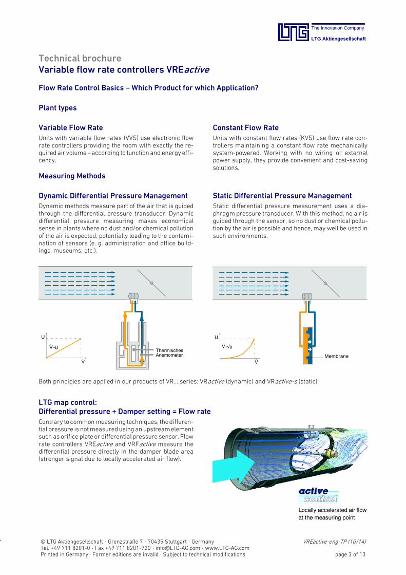
Dynamic Differential Pressure ManagementDynamic methods measure part of the air that is guidedthrough the differential pressure transducer. Dynamicdifferential pressure measuring makes economicalsense in plants where no dust and/or chemical pollutionof the air is expected, potentially leading to the contamination of sensors (e. g. administration and office buildings, museums, etc.).
U
V.
.V~U
ThermischesAnemometer
Static Differential Pressure Management
Static differential pressure measurement uses a dia-phragm pressure transducer. With this method, no air isguided through the sensor, so no dust or chemical pollution by the air is possible and hence, may well be used insuch environments.
U
VMembrane
V~U
.
.
Both principles are applied in our products of VR... series: VRactive (dynamic) and VRactive-s (static).
LTG map control:Differential pressure + Damper setting = Flow rate
Contrary to commonmeasuring techniques, thedifferential pressure isnotmeasuredusing an upstreamelementsuch as orifice plate or differential pressure sensor. Flowrate controllers VREactive and VRFactive measure thedifferential pressure directly in the damper blade area(stronger signal due to locally accelerated air flow).
Locally accelerated air flowat the measuring point
The Innovation Company
LTG Aktiengesellschaft
© LTG Aktiengesellschaft · Grenzstraße 7 · 70435 Stuttgart · Germany VREactive-eng-TP (10/14)Tel. +49 711 8201-0 · Fax +49 711 8201-720 · [email protected] · www.LTG-AG.comPrinted in Germany · Former editions are invalid · Subject to technical modifications page 4 of 13
Technical brochureVariable flow rate controllers VREactive
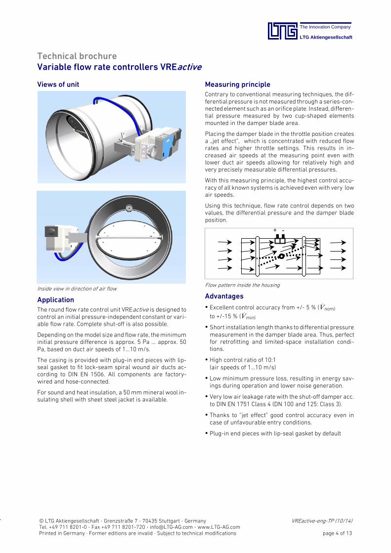
Views of unit
Inside view in direction of air flow
ApplicationThe round flow rate control unit VREactive is designed tocontrol an initial pressure-independent constant or variable flow rate. Complete shut-off is also possible.
Depending on themodel size and flow rate, theminimuminitial pressure difference is approx. 5 Pa ... approx. 50Pa, based on duct air speeds of 1...10 m/s.
The casing is provided with plug-in end pieces with lip-seal gasket to fit lock-seam spiral wound air ducts according to DIN EN 1506. All components are factory-wired and hoseconnected.
For sound and heat insulation, a 50mmmineral wool insulating shell with sheet steel jacket is available.
Measuring principleContrary to conventional measuring techniques, the differential pressure is notmeasured through a series-connectedelement such asan orifice plate. Instead, differential pressure measured by two cup-shaped elementsmounted in the damper blade area.
Placing the damper blade in the throttle position createsa „jet effect”, which is concentrated with reduced flowrates and higher throttle settings. This results in increased air speeds at the measuring point even withlower duct air speeds allowing for relatively high andvery precisely measurable differential pressures.
With this measuring principle, the highest control accuracy of all known systems is achievedevenwith very lowair speeds.
Using this technique, flow rate control depends on twovalues, the differential pressure and the damper bladeposition.
+ -
Flow pattern inside the housing
Advantages
Excellent control accuracy from +/- 5 % (V.
nom)
to +/-15 % (V.
min)
Short installation length thanks to differential pressuremeasurement in the damper blade area. Thus, perfectfor retrofitting and limited-space installation conditions.
High control ratio of 10:1(air speeds of 1...10 m/s)
Low minimum pressure loss, resulting in energy savings during operation and lower noise generation.
Very low air leakage ratewith the shut-off damper acc.to DIN EN 1751 Class 4 (DN 100 and 125: Class 3).
Thanks to ”jet effect” good control accuracy even incase of unfavourable entry conditions.
Plug-in end pieces with lip-seal gasket by default
The Innovation Company
LTG Aktiengesellschaft
© LTG Aktiengesellschaft · Grenzstraße 7 · 70435 Stuttgart · Germany VREactive-eng-TP (10/14)Tel. +49 711 8201-0 · Fax +49 711 8201-720 · [email protected] · www.LTG-AG.comPrinted in Germany · Former editions are invalid · Subject to technical modifications page 5 of 13
Technical brochureVariable flow rate controllers VREactive
Materials, finishes- Housing, damper, axle and and measuring probes ofgalvanized steel
- Damper bearings of POM plastic
- Sealings of EPDM
Accessories, special versions
- Insulating case for sound and heat insulation (retrofit)
- Flanges according to DIN 24154 R1 at both ends
- Flexible sound absorber SDE-AO made of aluminium
- Rigid sound absorber SDE-SO made of galvanizedsheet steel
- Compact controller compatible with MPBus or LON
- Compact controller with static measuring method
Additional accessories and special versions by request.
Connection
Notes and circuit diagrams for regulating the flow ratecan be found in the operating and maintenance instructions.
Recommendation for selection- Air speed up to 7 m/s
- Damper pressure loss up to 500 Pa
- If sound emission via air duct surfaces is critical, allducts including the controller must be sound insulatedup to the sound absorber
- For sound absorbers, the flownoise downstreamof thesplitters and the noise created by the increasedoutflowair speed in the connected fittingsmust be considered.
Application ranges and limits- Minimum air speed 1 m/s
- Nominal air speed 10 m/s
- Maximumair speed in the free case section 12m/swithspecific factory-set adjustment
- Static over-pressure in the air duct up to 1000 Pa
- Static under-pressure in the air duct based on ambientpressure 750 Pa max.
- Leakage flow rate via shut damper blade Class 4 acc. toDIN EN 1751 (DN 100 and 125: Class 3)
- Leakage flow rate via casing Class A acc. to DIN EN1751
- Operating temperature range 0 ...+50 °C at 5...95 % rh,non-condensing (acc. to EN 60730-1)
- Suitable for low-pollution air flows(e.g. ETA1, ETA2 acc. to DIN EN 13779),non-corrosive, aggressive air, without solvents thatmay affect the EPDM damper sealing
- Installation with horizontal damper axle only
- Free suction with upstream air duct or via fitting only
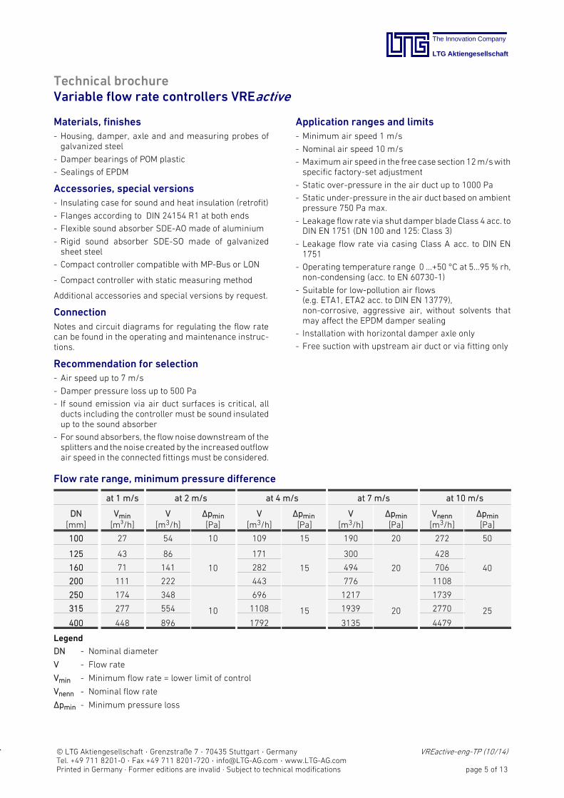
Flow rate range, minimum pressure difference
at 1 m/s at 2 m/s at 4 m/s at 7 m/s at 10 m/s
DN[mm]
Vmin
[m³/h]V
[m3/h]Δpmin
[Pa]V
[m3/h]Δpmin
[Pa]V
[m3/h]Δpmin
[Pa]Vnenn[m3/h]
Δpmin
[Pa]
100 27 54 10 109 15 190 20 272 50
125 43 86
10
171
15
300
20
428
40160 71 141 282 494 706
200 111 222 443 776 1108
250 174 348
10
696
15
1217
20
1739
25315 277 554 1108 1939 2770
400 448 896 1792 3135 4479
Legend
DN - Nominal diameter
V - Flow rate
Vmin - Minimum flow rate = lower limit of control
Vnenn - Nominal flow rate
Δpmin - Minimum pressure loss
The Innovation Company
LTG Aktiengesellschaft
© LTG Aktiengesellschaft · Grenzstraße 7 · 70435 Stuttgart · Germany VREactive-eng-TP (10/14)Tel. +49 711 8201-0 · Fax +49 711 8201-720 · [email protected] · www.LTG-AG.comPrinted in Germany · Former editions are invalid · Subject to technical modifications page 6 of 13
Technical brochureVariable flow rate controllers VREactive
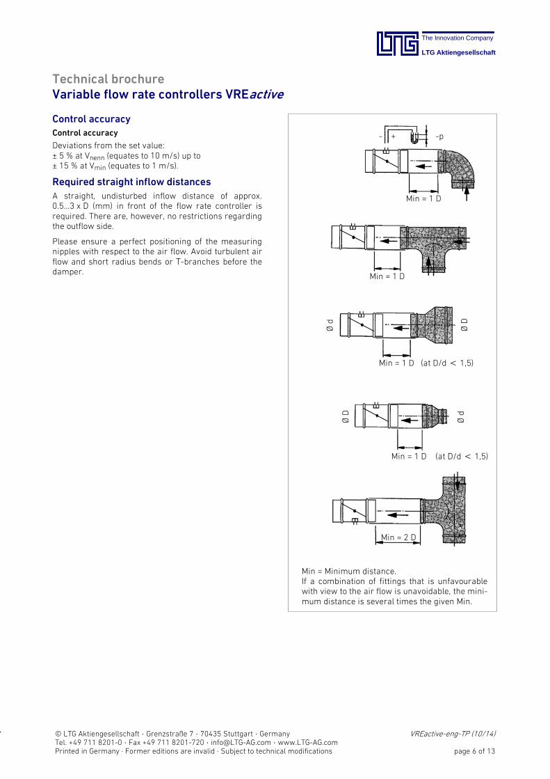
Control accuracyControl accuracy
Deviations from the set value:± 5 % at Vnenn (equates to 10 m/s) up to± 15 % at Vmin (equates to 1 m/s).
Required straight inflow distances
A straight, undisturbed inflow distance of approx.0.5...3 x D (mm) in front of the flow rate controller isrequired. There are, however, no restrictions regardingthe outflow side.
Please ensure a perfect positioning of the measuringnipples with respect to the air flow. Avoid turbulent airflow and short radius bends or T-branches before thedamper.
Min = 1 D
Min = 1 D
Min = 1 D (at D/d< 1,5)
Min = 1 D (at D/d< 1,5)
Min = 2 D
ØD
ØD
Ød
Ød
- + -p
Min = Minimum distance.If a combination of fittings that is unfavourablewith view to the air flow is unavoidable, the minimum distance is several times the given Min.
The Innovation Company
LTG Aktiengesellschaft
© LTG Aktiengesellschaft · Grenzstraße 7 · 70435 Stuttgart · Germany VREactive-eng-TP (10/14)Tel. +49 711 8201-0 · Fax +49 711 8201-720 · [email protected] · www.LTG-AG.comPrinted in Germany · Former editions are invalid · Subject to technical modifications page 7 of 13
Technical brochureVariable flow rate controllers VREactive
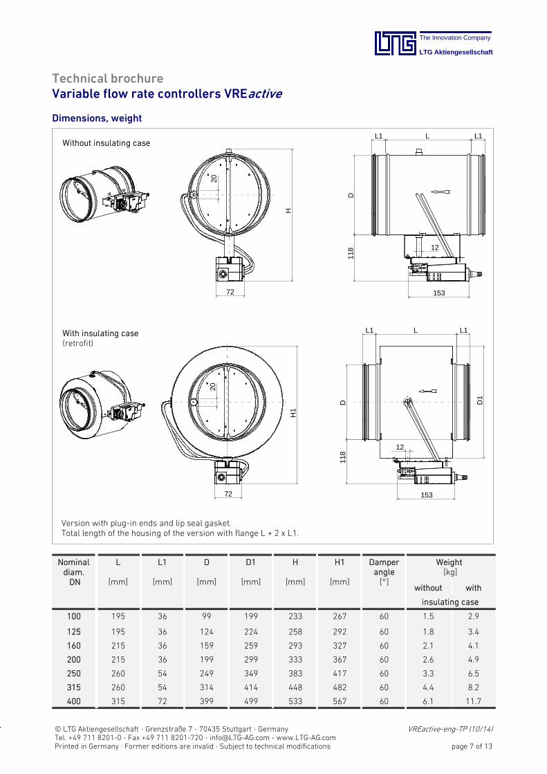
Dimensions, weight
LL1 L1
D11
8
153
12
20
H72
LL1 L1
D11
8
153
12
D1
20
H1
72
Without insulating case
With insulating case(retrofit)
Version with plug-in ends and lip seal gasket.Total length of the housing of the version with flange L + 2 x L1.
Nominaldiam.DN
L
[mm]
L1
[mm]
D
[mm]
D1
[mm]
H
[mm]
H1
[mm]
Damperangle[_]
Weight[kg]
without with
insulating case
100 195 36 99 199 233 267 60 1.5 2.9
125 195 36 124 224 258 292 60 1.8 3.4
160 215 36 159 259 293 327 60 2.1 4.1
200 215 36 199 299 333 367 60 2.6 4.9
250 260 54 249 349 383 417 60 3.3 6.5
315 260 54 314 414 448 482 60 4.4 8.2
400 315 72 399 499 533 567 60 6.1 11.7
The Innovation Company
LTG Aktiengesellschaft
© LTG Aktiengesellschaft · Grenzstraße 7 · 70435 Stuttgart · Germany VREactive-eng-TP (10/14)Tel. +49 711 8201-0 · Fax +49 711 8201-720 · [email protected] · www.LTG-AG.comPrinted in Germany · Former editions are invalid · Subject to technical modifications page 8 of 13
Technical brochureVariable flow rate controllers VREactive
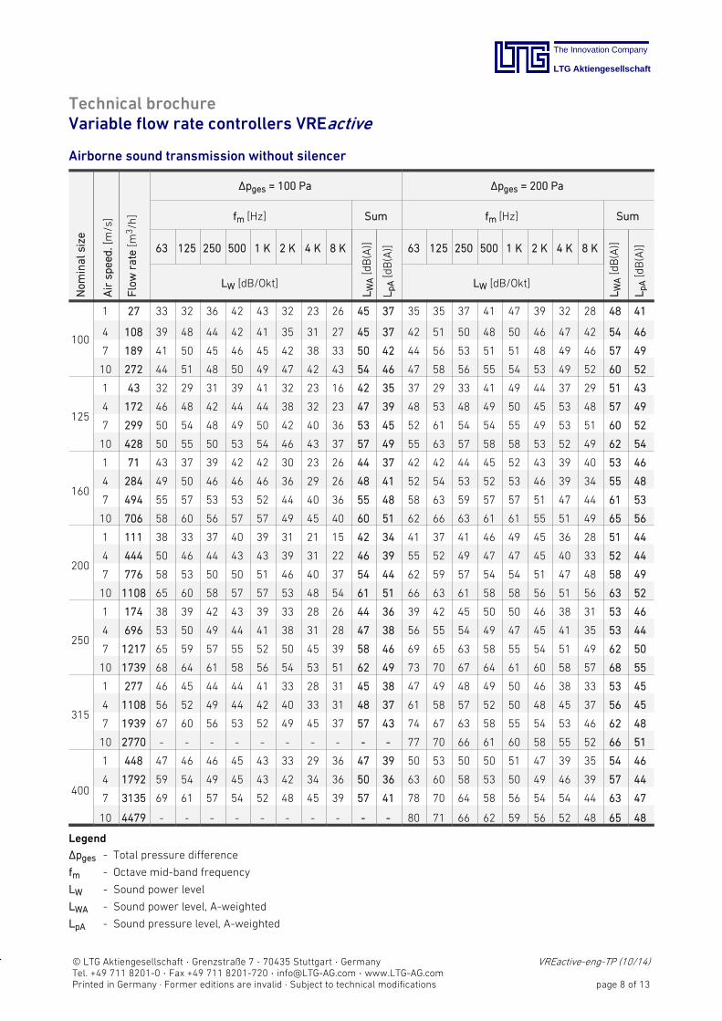
Airborne sound transmission without silencer
Nom
inalsize
Airsp
eed.[m/s]
Flow
rate
[m3/h
]
Δpges = 100 Pa Δpges = 200 Pa
fm [Hz] Sum fm [Hz] Sum
63 125 250 500 1 K 2 K 4 K 8 K
LWA[dB(A)]
LpA[dB(A)] 63 125 250 500 1 K 2 K 4 K 8 K
LWA[dB(A)]
LpA[dB(A)]
LW [dB/Okt] LW [dB/Okt]
100
1 27 33 32 36 42 43 32 23 26 45 37 35 35 37 41 47 39 32 28 48 41
4 108 39 48 44 42 41 35 31 27 45 37 42 51 50 48 50 46 47 42 54 46
7 189 41 50 45 46 45 42 38 33 50 42 44 56 53 51 51 48 49 46 57 49
10 272 44 51 48 50 49 47 42 43 54 46 47 58 56 55 54 53 49 52 60 52
125
1 43 32 29 31 39 41 32 23 16 42 35 37 29 33 41 49 44 37 29 51 43
4 172 46 48 42 44 44 38 32 23 47 39 48 53 48 49 50 45 53 48 57 49
7 299 50 54 48 49 50 42 40 36 53 45 52 61 54 54 55 49 53 51 60 52
10 428 50 55 50 53 54 46 43 37 57 49 55 63 57 58 58 53 52 49 62 54
160
1 71 43 37 39 42 42 30 23 26 44 37 42 42 44 45 52 43 39 40 53 46
4 284 49 50 46 46 46 36 29 26 48 41 52 54 53 52 53 46 39 34 55 48
7 494 55 57 53 53 52 44 40 36 55 48 58 63 59 57 57 51 47 44 61 53
10 706 58 60 56 57 57 49 45 40 60 51 62 66 63 61 61 55 51 49 65 56
200
1 111 38 33 37 40 39 31 21 15 42 34 41 37 41 46 49 45 36 28 51 44
4 444 50 46 44 43 43 39 31 22 46 39 55 52 49 47 47 45 40 33 52 44
7 776 58 53 50 50 51 46 40 37 54 44 62 59 57 54 54 51 47 48 58 49
10 1108 65 60 58 57 57 53 48 54 61 51 66 63 61 58 58 56 51 56 63 52
250
1 174 38 39 42 43 39 33 28 26 44 36 39 42 45 50 50 46 38 31 53 46
4 696 53 50 49 44 41 38 31 28 47 38 56 55 54 49 47 45 41 35 53 44
7 1217 65 59 57 55 52 50 45 39 58 46 69 65 63 58 55 54 51 49 62 50
10 1739 68 64 61 58 56 54 53 51 62 49 73 70 67 64 61 60 58 57 68 55
315
1 277 46 45 44 44 41 33 28 31 45 38 47 49 48 49 50 46 38 33 53 45
4 1108 56 52 49 44 42 40 33 31 48 37 61 58 57 52 50 48 45 37 56 45
7 1939 67 60 56 53 52 49 45 37 57 43 74 67 63 58 55 54 53 46 62 48
10 2770 - 77 70 66 61 60 58 55 52 66 51
400
1 448 47 46 46 45 43 33 29 36 47 39 50 53 50 50 51 47 39 35 54 46
4 1792 59 54 49 45 43 42 34 36 50 36 63 60 58 53 50 49 46 39 57 44
7 3135 69 61 57 54 52 48 45 39 57 41 78 70 64 58 56 54 54 44 63 47
10 4479 - 80 71 66 62 59 56 52 48 65 48
Legend
Δpges - Total pressure difference
fm - Octave mid-band frequency
LW - Sound power level
LWA - Sound power level, A-weighted
LpA - Sound pressure level, A-weighted
The Innovation Company
LTG Aktiengesellschaft
© LTG Aktiengesellschaft · Grenzstraße 7 · 70435 Stuttgart · Germany VREactive-eng-TP (10/14)Tel. +49 711 8201-0 · Fax +49 711 8201-720 · [email protected] · www.LTG-AG.comPrinted in Germany · Former editions are invalid · Subject to technical modifications page 9 of 13
Technical brochureVariable flow rate controllers VREactive
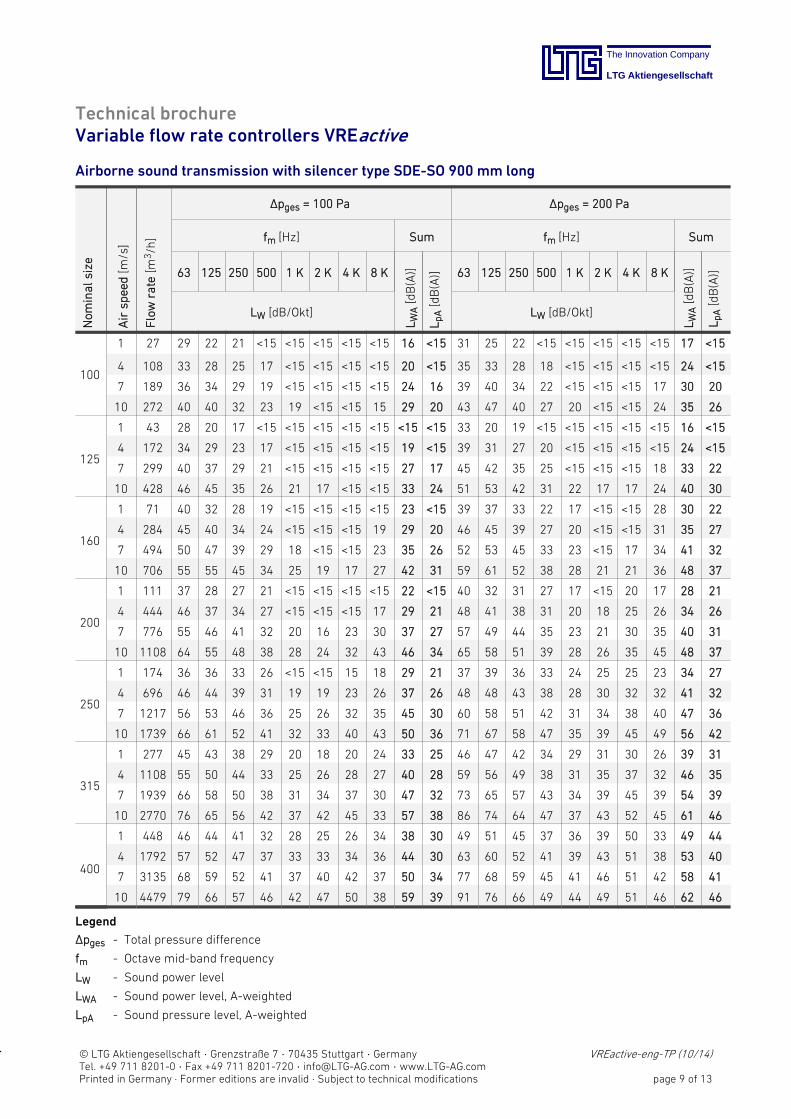
Airborne sound transmission with silencer type SDE-SO 900 mm long
Nom
inalsize
Airsp
eed[m
/s]
Flow
rate
[m3/h
]
Δpges = 100 Pa Δpges = 200 Pa
fm [Hz] Sum fm [Hz] Sum
63 125 250 500 1 K 2 K 4 K 8 K
LWA[dB(A)]
LpA[dB(A)] 63 125 250 500 1 K 2 K 4 K 8 K
LWA[dB(A)]
LpA[dB(A)]
LW [dB/Okt] LW [dB/Okt]
100
1 27 29 22 21 <15 <15 <15 <15 <15 16 <15 31 25 22 <15 <15 <15 <15 <15 17 <15
4 108 33 28 25 17 <15 <15 <15 <15 20 <15 35 33 28 18 <15 <15 <15 <15 24 <15
7 189 36 34 29 19 <15 <15 <15 <15 24 16 39 40 34 22 <15 <15 <15 17 30 20
10 272 40 40 32 23 19 <15 <15 15 29 20 43 47 40 27 20 <15 <15 24 35 26
125
1 43 28 20 17 <15 <15 <15 <15 <15 <15 <15 33 20 19 <15 <15 <15 <15 <15 16 <15
4 172 34 29 23 17 <15 <15 <15 <15 19 <15 39 31 27 20 <15 <15 <15 <15 24 <15
7 299 40 37 29 21 <15 <15 <15 <15 27 17 45 42 35 25 <15 <15 <15 18 33 22
10 428 46 45 35 26 21 17 <15 <15 33 24 51 53 42 31 22 17 17 24 40 30
160
1 71 40 32 28 19 <15 <15 <15 <15 23 <15 39 37 33 22 17 <15 <15 28 30 22
4 284 45 40 34 24 <15 <15 <15 19 29 20 46 45 39 27 20 <15 <15 31 35 27
7 494 50 47 39 29 18 <15 <15 23 35 26 52 53 45 33 23 <15 17 34 41 32
10 706 55 55 45 34 25 19 17 27 42 31 59 61 52 38 28 21 21 36 48 37
200
1 111 37 28 27 21 <15 <15 <15 <15 22 <15 40 32 31 27 17 <15 20 17 28 21
4 444 46 37 34 27 <15 <15 <15 17 29 21 48 41 38 31 20 18 25 26 34 26
7 776 55 46 41 32 20 16 23 30 37 27 57 49 44 35 23 21 30 35 40 31
10 1108 64 55 48 38 28 24 32 43 46 34 65 58 51 39 28 26 35 45 48 37
250
1 174 36 36 33 26 <15 <15 15 18 29 21 37 39 36 33 24 25 25 23 34 27
4 696 46 44 39 31 19 19 23 26 37 26 48 48 43 38 28 30 32 32 41 32
7 1217 56 53 46 36 25 26 32 35 45 30 60 58 51 42 31 34 38 40 47 36
10 1739 66 61 52 41 32 33 40 43 50 36 71 67 58 47 35 39 45 49 56 42
315
1 277 45 43 38 29 20 18 20 24 33 25 46 47 42 34 29 31 30 26 39 31
4 1108 55 50 44 33 25 26 28 27 40 28 59 56 49 38 31 35 37 32 46 35
7 1939 66 58 50 38 31 34 37 30 47 32 73 65 57 43 34 39 45 39 54 39
10 2770 76 65 56 42 37 42 45 33 57 38 86 74 64 47 37 43 52 45 61 46
400
1 448 46 44 41 32 28 25 26 34 38 30 49 51 45 37 36 39 50 33 49 44
4 1792 57 52 47 37 33 33 34 36 44 30 63 60 52 41 39 43 51 38 53 40
7 3135 68 59 52 41 37 40 42 37 50 34 77 68 59 45 41 46 51 42 58 41
10 4479 79 66 57 46 42 47 50 38 59 39 91 76 66 49 44 49 51 46 62 46
Legend
Δpges - Total pressure difference
fm - Octave mid-band frequency
LW - Sound power level
LWA - Sound power level, A-weighted
LpA - Sound pressure level, A-weighted
The Innovation Company
LTG Aktiengesellschaft
© LTG Aktiengesellschaft · Grenzstraße 7 · 70435 Stuttgart · Germany VREactive-eng-TP (10/14)Tel. +49 711 8201-0 · Fax +49 711 8201-720 · [email protected] · www.LTG-AG.comPrinted in Germany · Former editions are invalid · Subject to technical modifications page 10 of 13
Technical brochureVariable flow rate controllers VREactive
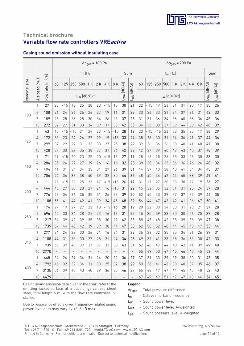
Casing sound emission without insulating case
Nom
inalsize
Ais
pee
d[m
/s]
Fow
rate
[m3/h
]
Δpges = 100 Pa Δpges = 200 Pa
fm [Hz] Sum fm [Hz] Sum
63 125 250 500 1 K 2 K 4 K 8 K
LWA[dB(A)]
LpA[dB(A)] 63 125 250 500 1 K 2 K 4 K 8 K
LWA[dB(A)]
LpA[dB(A)]
LW [dB/Okt] LW [dB/Okt]
100
1 27 20 <15 18 25 28 23 <15 15 30 21 22 <15 19 23 31 31 20 17 35 26
4 108 26 24 26 25 26 27 19 16 31 22 30 26 33 31 34 37 36 31 42 33
7 189 28 25 28 28 30 34 26 23 37 28 31 31 36 34 36 40 38 36 45 36
10 272 32 27 31 33 34 39 31 33 42 33 34 33 38 37 39 44 38 42 48 39
125
1 43 18 <15 <15 21 24 23 <15 <15 28 19 23 <15 <15 23 33 35 25 17 38 29
4 172 33 23 24 26 27 29 19 <15 33 24 35 28 30 31 34 36 41 37 44 36
7 299 37 29 29 31 33 33 27 25 38 29 39 36 36 36 38 40 41 40 47 38
10 428 37 30 32 35 38 37 31 26 42 33 42 37 39 40 42 43 40 37 48 39
160
1 71 29 <15 20 23 25 20 <15 16 27 19 28 16 25 26 35 33 26 30 38 30
4 284 35 24 27 27 29 26 16 16 32 23 38 28 34 33 36 36 26 24 40 32
7 494 41 31 34 34 35 34 27 26 39 31 44 37 40 38 40 41 34 34 45 37
10 706 44 34 37 38 40 39 32 30 44 35 48 40 44 42 44 45 38 39 49 41
200
1 111 28 <15 22 25 23 17 <15 <15 26 17 31 17 27 30 33 30 22 19 36 27
4 444 40 27 30 28 27 24 16 <15 31 22 45 32 35 32 31 31 25 24 37 28
7 776 48 34 36 35 35 31 26 28 39 30 52 40 43 39 37 37 33 39 44 35
10 1108 55 41 44 42 41 39 34 45 48 39 56 44 47 43 42 41 36 47 50 41
250
1 174 27 19 27 27 22 18 <15 16 28 19 28 22 30 34 33 31 23 21 37 28
4 696 42 30 34 28 24 23 16 18 31 22 45 35 39 33 30 30 26 25 37 28
7 1217 54 39 42 39 35 35 30 29 42 33 58 45 48 42 38 39 36 39 47 38
10 1739 57 44 46 42 39 39 38 41 47 38 62 50 52 48 44 45 43 47 53 44
315
1 277 34 24 28 30 26 21 16 24 31 22 35 28 32 35 35 34 26 26 39 31
4 1108 44 31 33 30 27 28 21 24 34 25 49 37 41 38 35 36 33 30 42 33
7 1939 55 39 40 39 37 37 33 30 43 34 62 46 47 44 40 42 41 39 49 40
10 2770 - 65 49 50 47 45 46 43 45 52 44
400
1 448 34 24 29 34 31 24 20 32 36 27 37 31 33 39 39 38 30 31 43 35
4 1792 46 32 32 34 31 33 25 32 38 29 50 38 41 42 38 40 37 35 46 37
7 3135 56 39 40 43 40 39 36 35 46 37 65 48 47 47 44 45 45 40 52 43
10 4479 - 67 49 49 51 47 47 43 44 54 45
Casing soundemission data given in the chart refer to theemitting jacket surface of a duct of galvanized sheetsteel, total length 6 m, with the flow rate controller installed.
Due to resonance effects given frequency-related soundpower level data may vary by +/- 6 dB max.
Legend
Δpges - Total pressure difference
fm - Octave mid-band frequency
LW - Sound power level
LWA - Sound power level, A-weighted
LpA - Sound pressure level, A-weighted
The Innovation Company
LTG Aktiengesellschaft
© LTG Aktiengesellschaft · Grenzstraße 7 · 70435 Stuttgart · Germany VREactive-eng-TP (10/14)Tel. +49 711 8201-0 · Fax +49 711 8201-720 · [email protected] · www.LTG-AG.comPrinted in Germany · Former editions are invalid · Subject to technical modifications page 11 of 13
Technical brochureVariable flow rate controllers VREactive
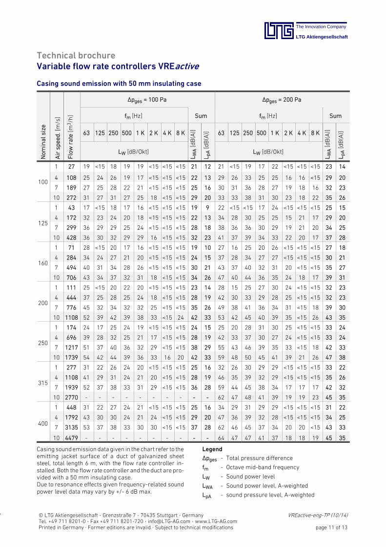
Casing sound emission with 50 mm insulating case
Nom
inalsize
Airsp
eed.[m/s]
Flow
rate
[m3/h
]
Δpges = 100 Pa Δpges = 200 Pa
fm [Hz] Sum fm [Hz] Sum
63 125 250 500 1 K 2 K 4 K 8 K
LWA[dB(A)]
LpA[dB(A)] 63 125 250 500 1 K 2 K 4 K 8 K
LWA[dB(A)]
LpA[dB(A)]
LW [dB/Okt] LW [dB/Okt]
100
1 27 19 <15 18 19 19 <15 <15 <15 21 12 21 <15 19 17 22 <15 <15 <15 23 14
4 108 25 24 26 19 17 <15 <15 <15 22 13 29 26 33 25 25 16 16 <15 29 20
7 189 27 25 28 22 21 <15 <15 <15 25 16 30 31 36 28 27 19 18 16 32 23
10 272 31 27 31 27 25 18 <15 <15 29 20 33 33 38 31 30 23 18 22 35 26
125
1 43 17 <15 18 17 16 <15 <15 <15 19 9 22 <15 <15 17 24 <15 <15 <15 25 15
4 172 32 23 24 20 18 <15 <15 <15 22 13 34 28 30 25 25 15 21 17 29 20
7 299 36 29 29 25 24 <15 <15 <15 28 18 38 36 36 30 29 19 21 20 34 25
10 428 36 30 32 29 29 16 <15 <15 32 23 41 37 39 34 33 22 20 17 37 28
160
1 71 28 <15 20 17 16 <15 <15 <15 19 10 27 16 25 20 26 <15 <15 <15 27 18
4 284 34 24 27 21 20 <15 <15 <15 24 15 37 28 34 27 27 <15 <15 <15 30 21
7 494 40 31 34 28 26 <15 <15 <15 30 21 43 37 40 32 31 20 <15 <15 35 27
10 706 43 34 37 32 31 18 <15 <15 34 26 47 40 44 36 35 24 18 17 39 31
200
1 111 25 <15 20 22 20 <15 <15 <15 23 14 28 15 25 27 30 24 <15 <15 32 23
4 444 37 25 28 25 24 18 <15 <15 28 19 42 30 33 29 28 25 <15 <15 32 23
7 776 45 32 34 32 32 25 <15 <15 35 26 49 38 41 36 34 31 <15 18 39 30
10 1108 52 39 42 39 38 33 <15 24 42 33 53 42 45 40 39 35 <15 26 43 35
250
1 174 24 17 25 24 19 <15 <15 <15 24 15 25 20 28 31 30 25 <15 <15 33 24
4 696 39 28 32 25 21 17 <15 <15 28 19 42 33 37 30 27 24 <15 <15 33 24
7 1217 51 37 40 36 32 29 <15 <15 38 29 55 43 46 39 35 33 <15 18 42 33
10 1739 54 42 44 39 36 33 16 20 42 33 59 48 50 45 41 39 21 26 47 38
315
1 277 31 22 26 24 20 <15 <15 <15 25 16 32 26 30 29 29 <15 <15 <15 33 22
4 1108 41 29 31 24 21 20 <15 <15 28 19 46 35 39 32 29 <15 <15 <15 35 26
7 1939 52 37 38 33 31 29 <15 <15 36 28 59 44 45 38 34 17 17 17 42 32
10 2770 62 47 48 41 39 19 19 23 45 35
400
1 448 31 22 27 24 21 <15 <15 <15 25 16 34 29 31 29 29 <15 <15 <15 31 22
4 1792 43 30 30 24 21 24 <15 <15 29 20 47 36 39 32 28 <15 <15 <15 34 25
7 3135 53 37 38 33 30 30 <15 <15 37 28 62 46 45 37 34 20 20 <15 43 33
10 4479 64 47 47 41 37 18 18 19 45 35
Casing soundemission data given in the chart refer to theemitting jacket surface of a duct of galvanized sheetsteel, total length 6 m, with the flow rate controller installed. Both the flowrate controller and theduct areprovided with a 50 mm insulating case.Due to resonance effects given frequency-related soundpower level data may vary by +/- 6 dB max.
Legend
Δpges - Total pressure difference
fm - Octave mid-band frequency
LW - Sound power level
LWA - Sound power level, A-weighted
LpA - sound pressure level, A-weighted
The Innovation Company
LTG Aktiengesellschaft
© LTG Aktiengesellschaft · Grenzstraße 7 · 70435 Stuttgart · Germany VREactive-eng-TP (10/14)Tel. +49 711 8201-0 · Fax +49 711 8201-720 · [email protected] · www.LTG-AG.comPrinted in Germany · Former editions are invalid · Subject to technical modifications page 12 of 13
Technical brochureVariable flow rate controllers VREactive
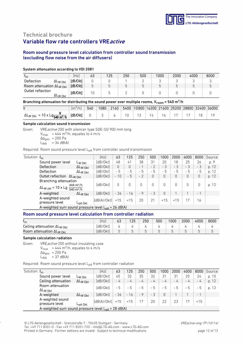
Room sound pressure level calculation from controller sound transmission(excluding flow noise from the air diffusers)
System attenuation according to VDI 2081
fm [Hz] 63 125 250 500 1000 2000 4000 8000
Deflection ΔLW Okt [dB/Okt] 0 0 1 2 3 3 3 3Room attenuation ΔLW Okt [dB/Okt] 5 5 5 5 5 5 5 5Outlet reflection
ΔLW Okt[dB/Okt] 10 5 2 0 0 0 0 0
Branching attenuation for distributing the sound power over multiple rooms, Vroom = 540 m³/h
V [m³/h] 540 1080 2160 5400 10800 16200 21600 25200 28800 32400 36000
ΔLW Okt = 10 x Lg V540 m³∕h [dB/Okt] 0 3 6 10 13 14 16 17 17 18 19
Sample calculation sound transmission
Given: VREactive 200 with silencer type SDE-SO 900 mm longVmax = 444 m³/h, equates to 4 m/sΔpges = 200 PaLWA = 34 dB(A)
Required: Room sound pressure level LpA from controller sound transmission
Solution: fm [Hz] 63 125 250 500 1000 2000 4000 8000 SourceSound power level LW Okt [dB/Okt] 48 41 38 31 20 18 25 26 p. 9Deflection ΔLW Okt [dB/Okt] 0 0 - 1 - 2 - 3 - 3 - 3 - 3 p. 12Deflection ΔLW Okt [dB/Okt] - 5 - 5 - 5 - 5 - 5 - 5 - 5 - 5 p. 12Outlet reflection ΔLW Okt [dB/Okt] - 10 - 5 - 2 0 0 0 0 0 p. 12Branching attenuation
444 m³∕h540 m³∕hΔLW okt = 10 x Lg
[dB/Okt] 0 0 0 0 0 0 0 0 p. 12
A-weighted ΔLW Okt [dB/Okt] - 26 - 16 - 9 - 3 0 1 1 - 1A-weighted soundpressure level LpA Okt
[dB(A)/Okt] <15 <15 20 21 <15 <15 17 16
A-weighted sum sound pressure level LpA = 26 dB(A)
Room sound pressure level calculation from controller radiation
fm [Hz] 63 125 250 500 1000 2000 4000 8000
Ceiling attenuation ΔLW Okt [dB/Okt] 4 4 4 4 4 4 4 4Room attenuation ΔLW Okt [dB/Okt] 5 5 5 5 5 5 5 5
Sample calculation radiation
Given: VREactive 200 without insulating caseVmax = 444 m³/h, equates to 4 m/sΔpges = 200 PaLWA = 37 dB(A)
Required: Room sound pressure level LpA from controller radiation
Solution: fm [Hz] 63 125 250 500 1000 2000 4000 8000 SourceSound power level LW Okt [dB/Okt] 45 32 35 32 31 31 25 24 p. 10Ceiling attenuation ΔLW Okt [dB/Okt] - 4 - 4 - 4 - 4 - 4 - 4 - 4 - 4 p. 12Room attenuationΔLW Okt
[dB/Okt] - 5 - 5 - 5 - 5 - 5 - 5 - 5 - 5 p. 12
A-weighted ΔLW Okt [dB/Okt] - 26 - 16 - 9 - 3 0 1 1 - 1A-weghted soundpressure level LpA Okt
[dB(A)/Okt] <15 <15 17 20 22 23 17 <15
A-weighted sum sound pressure level LpA = 28 dB(A)
The Innovation Company
LTG Aktiengesellschaft
© LTG Aktiengesellschaft · Grenzstraße 7 · 70435 Stuttgart · Germany VREactive-eng-TP (10/14)Tel. +49 711 8201-0 · Fax +49 711 8201-720 · [email protected] · www.LTG-AG.comPrinted in Germany · Former editions are invalid · Subject to technical modifications page 13 of 13
Technical brochureVariable flow rate controllers VREactive
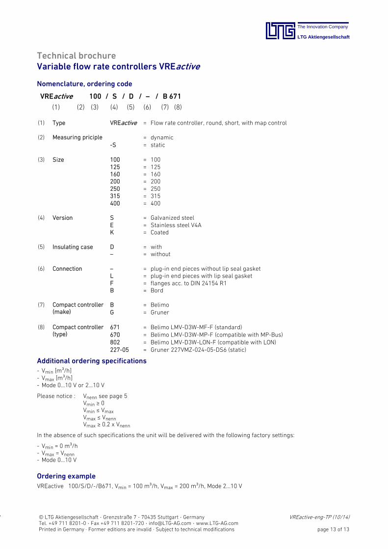
Nomenclature, ordering code
VREactive 100 / S / D / – / B 671
(1) (2) (3) (4) (5) (6) (7) (8)
(1) Type VREactive = Flow rate controller, round, short, with map control
(2) Measuring priciple = dynamicS = static
(3) Size 100 = 100125 = 125160 = 160200 = 200250 = 250315 = 315400 = 400
(4) Version S = Galvanized steelE = Stainless steel V4AK = Coated
(5) Insulating case D = with– = without
(6) Connection – = plug-in end pieces without lip seal gasketL = plug-in end pieces with lip seal gasketF = flanges acc. to DIN 24154 R1B = Bord
(7) Compact controller(make)
B = BelimoG = Gruner
(8) Compact controller(type)
671 = Belimo LMVD3WMFF (standard)670 = Belimo LMVD3WMPF (compatible with MPBus)802 = Belimo LMVD3WLONF (compatible with LON)22705 = Gruner 227VMZ024-05-DS6 (static)
Additional ordering specifications
- Vmin [m³/h]- Vmax [m³/h]- Mode 0...10 V or 2...10 V
Please notice : Vnenn see page 5Vmin ≥ 0Vmin ≤ VmaxVmax ≤ VnennVmax ≥ 0.2 x Vnenn
In the absence of such specifications the unit will be delivered with the following factory settings:
- Vmin = 0 m³/h- Vmax = Vnenn- Mode 0...10 V
Ordering example
VREactive 100/S/D//B671, Vmin = 100 m³/h, Vmax = 200 m³/h, Mode 2...10 V
1.Dient zur Identifizierung der letzten Seite

The Innovation Company
LTG Aktiengesellschaft
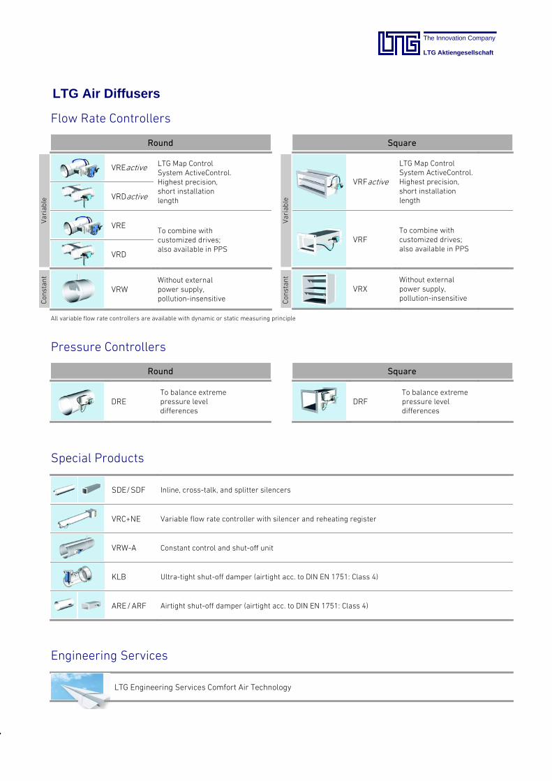
LTG Air Diffusers
VRFactive
LTG Map ControlSystem ActiveControl.Highest precision,short installationlength
VRFTo combine withcustomized drives;also available in PPS
VRXWithout externalpower supply,pollution-insensitive
VREactive LTG Map ControlSystem ActiveControl.Highest precision,short installationlengthVRDactive
VRETo combine withcustomized drives;also available in PPS
VRD
VRWWithout externalpower supply,pollution-insensitive
DRETo balance extremepressure leveldifferences
DRFTo balance extremepressure leveldifferences
Variable
Constant
Variable
Constant
All variable flow rate controllers are available with dynamic or static measuring principle
Flow Rate Controllers
Round
Round Square
Square
LTG Engineering Services Comfort Air Technology
Pressure Controllers
SDE/SDF Inline, cross-talk, and splitter silencers
VRC+NE Variable flow rate controller with silencer and reheating register
VRW-A Constant control and shut-off unit
KLB Ultra-tight shut-off damper (airtight acc. to DIN EN 1751: Class 4)
ARE/ARF Airtight shut-off damper (airtight acc. to DIN EN 1751: Class 4)
Special Products
Engineering Services
The Innovation Company
LTG Aktiengesellschaft
LTG Aktiengesellschaft
Grenzstraße 7
70435 Stuttgart
Germany
Tel.: +49 (711) 8201-0
Fax: +49 (711) 8201-720
E-Mail: [email protected]
www.LTG-AG.com
LTG Incorporated
105 Corporate Drive, Suite E
Spartanburg, SC 29303
USA
Tel..: +1 (864) 599-6340
Fax: +1 (864) 599-6344
E-Mail: [email protected]
www.LTG-INC.net
VREactive-eng-TP (10/14) 429-28E LTG Aktiengesellschaft • Former editions are invalid • Subject to technical modifications
Comfort Air Technology
Air-Water Systems
Air Diffusers
Air Distribution
Process Air Technology
Fans
Filtration technology
Humidification Technology
Engineering Services
Air flow tests
Thermodynamics
Acoustics / Comfort
Customised solutions