Technical Background Document on the Efficiency … · Technical Background Document on the...
66
Transcript of Technical Background Document on the Efficiency … · Technical Background Document on the...
Technical Background Document on the Efficiency andEffectiveness of CKD Landfill Design Elements
D R A F T
July 18, 1997
Prepared for: U.S. Environmental Protection AgencyOffice of Solid Waste (5302W)
2800 Crystal City DriveCrystal City, VA 20202
Prepared by: Science Applications International Corporation1710 Goodridge Drive
McLean VA 22102
EPA Contract 68-W4-0030, Work Assignment 215SAIC Project 01-0857-07-7389-160
Draft Technical Background Document on theEfficiency and Effectiveness of CKD Landfill Design Elements
i
TABLE OF CONTENTS
1.0 INTRODUCTION . . . . . . . . . . . . . . . . . . . . . . . . . . . . . . . . . . . . . . . . . . . . . . . . . . . . . 11.1 Background and Objectives . . . . . . . . . . . . . . . . . . . . . . . . . . . . . . . . . . . . . . . . 11.2 Approach/Methodology . . . . . . . . . . . . . . . . . . . . . . . . . . . . . . . . . . . . . . . . . . . 1
2.0 BASIS FOR COMPARING FLY ASH LANDFILLS TO PROPOSED CKD LANDFILLDESIGN ELEMENTS . . . . . . . . . . . . . . . . . . . . . . . . . . . . . . . . . . . . . . . . . . . . . . . . . . 32.1 Coal Ash Waste Generation . . . . . . . . . . . . . . . . . . . . . . . . . . . . . . . . . . . . . . . . 32.2 Coal Ash Waste Management . . . . . . . . . . . . . . . . . . . . . . . . . . . . . . . . . . . . . . . 32.3 Physical Characteristics of Ash and CKD . . . . . . . . . . . . . . . . . . . . . . . . . . . . . . 52.4 Chemical Characteristics of Ash and CKD . . . . . . . . . . . . . . . . . . . . . . . . . . . . . 5
3.0 PROPOSED OPERATING CRITERIA AND DEFAULT TECHNICAL STANDARDSFOR CKD LANDFILL DESIGN . . . . . . . . . . . . . . . . . . . . . . . . . . . . . . . . . . . . . . . . . . 83.1 Fugitive Dust Control . . . . . . . . . . . . . . . . . . . . . . . . . . . . . . . . . . . . . . . . . . . . . 83.2 Temporary Cap/Cover Material Requirements . . . . . . . . . . . . . . . . . . . . . . . . . . 93.3 Run-On/Run-Off Controls and Surface Water Requirements . . . . . . . . . . . . . . . . 93.4 Bottom Liner Requirements for New or Laterally Expanding CKD Landfills . . . 10
3.4.1 Default Technical Standard for Units in Karst Areas (Composite Liner andLeachate Collection System) . . . . . . . . . . . . . . . . . . . . . . . . . . . . . . . . . 10
3.4.2 Performance-Based Design for Units in Non-Karstic Areas . . . . . . . . . . 103.5 Ground Water Monitoring and Corrective Action . . . . . . . . . . . . . . . . . . . . . . . 113.6 Closure and Post-Closure Requirements . . . . . . . . . . . . . . . . . . . . . . . . . . . . . 12
4.0 COAL ASH LANDFILLS SELECTED FOR STUDY . . . . . . . . . . . . . . . . . . . . . . . . . 134.1 Ash Landfill Identification and Screening Methodology . . . . . . . . . . . . . . . . . . 134.2 Candidate Landfills Selected for Further Study . . . . . . . . . . . . . . . . . . . . . . . . . 134.3 Environmental Setting and Engineering Characteristics of Selected Landfills . . . 14
4.3.1 Conemaugh Ash Disposal Site . . . . . . . . . . . . . . . . . . . . . . . . . . . . . . . . 154.3.2 Montour Ash Storage Areas 2 and 3 . . . . . . . . . . . . . . . . . . . . . . . . . . . 164.3.3 Shawville Ash Disposal Site . . . . . . . . . . . . . . . . . . . . . . . . . . . . . . . . . 164.3.4 Beagle Club Ash Disposal Site/Titus Generating Station . . . . . . . . . . . . 17
5.0 EVALUATION OF PROPOSED LANDFILL DESIGN ELEMENTS . . . . . . . . . . . . . 195.1 Fugitive Dust Controls . . . . . . . . . . . . . . . . . . . . . . . . . . . . . . . . . . . . . . . . . . . 19
5.1.1 Fugitive Dust Control Technologies Applied At Fly Ash Landfills . . . . . 195.1.2 Effectiveness in Controlling Fugitive Dust Emissions . . . . . . . . . . . . . . . 19
Notes
Point and click to go directly to topics.
Draft Technical Background Document on theEfficiency and Effectiveness of CKD Landfill Design Elements
ii
5.2 Temporary Cap or Daily Cover . . . . . . . . . . . . . . . . . . . . . . . . . . . . . . . . . . . . . 225.2.1 Summary of Temporary Cap or Daily Cover Technologies Used At Fly Ash
Landfills . . . . . . . . . . . . . . . . . . . . . . . . . . . . . . . . . . . . . . . . . . . . . . . . 225.2.2 Effectiveness of Covers Installed Prior to Site Closure . . . . . . . . . . . . . 22
5.3 Ground-Water Monitoring . . . . . . . . . . . . . . . . . . . . . . . . . . . . . . . . . . . . . . . . 245.3.1 Summary of Ground-Water Monitoring Practices at Fly Ash Landfills . . 245.3.2 Effectiveness of Ground Water Monitoring Systems in Detecting Releases
From Fly Ash Landfills . . . . . . . . . . . . . . . . . . . . . . . . . . . . . . . . . . . . . 255.4 Storm Water Run-On/Run-Off Controls and Surface Water Controls . . . . . . . . 28
5.4.1 Storm Water Run-On/Run-Off Controls and Surface Water Controls atEmployed At Fly Ash Landfills . . . . . . . . . . . . . . . . . . . . . . . . . . . . . . . 29
5.4.2 Effectiveness of Storm Water Controls . . . . . . . . . . . . . . . . . . . . . . . . . 305.5 Composite Bottom Liner with Leachate Collection . . . . . . . . . . . . . . . . . . . . . . 31
5.5.1 Use of Composite Liners and Leachate Collection at Fly Ash Landfills . 325.5.2 Effectiveness of Plastic Bottom Liners for Controlling Releases to Ground
Water . . . . . . . . . . . . . . . . . . . . . . . . . . . . . . . . . . . . . . . . . . . . . . . . . . 345.6 Alternative Liner Designs . . . . . . . . . . . . . . . . . . . . . . . . . . . . . . . . . . . . . . . . . 35
5.6.1 Use of Alternative Liner Designs at Fly Ash Landfills . . . . . . . . . . . . . . 355.6.2 Effectiveness in Controlling Releases to Ground Water . . . . . . . . . . . . . 35
5.7 Landfill Closure and Post-Closure Measures at Fly Ash Landfills . . . . . . . . . . . 365.7.1 Summary of Closure and Post-Closure Activities at Fly Ash Landfills . . 365.7.2 Effectiveness of Closure . . . . . . . . . . . . . . . . . . . . . . . . . . . . . . . . . . . . 36
6.0 CONCLUSIONS . . . . . . . . . . . . . . . . . . . . . . . . . . . . . . . . . . . . . . . . . . . . . . . . . . . . . 386.1 Fugitive Dust Controls . . . . . . . . . . . . . . . . . . . . . . . . . . . . . . . . . . . . . . . . . . . 386.2 Temporary or Interim Landfill Cover . . . . . . . . . . . . . . . . . . . . . . . . . . . . . . . . 386.3 Ground-Water Monitoring . . . . . . . . . . . . . . . . . . . . . . . . . . . . . . . . . . . . . . . . 396.4 Storm Water Controls . . . . . . . . . . . . . . . . . . . . . . . . . . . . . . . . . . . . . . . . . . . 406.5 Composite Bottom Liner . . . . . . . . . . . . . . . . . . . . . . . . . . . . . . . . . . . . . . . . . 406.6 Alternative Bottom Liner Designs . . . . . . . . . . . . . . . . . . . . . . . . . . . . . . . . . . . 416.7 Landfill Closure and Post-Closure Measures . . . . . . . . . . . . . . . . . . . . . . . . . . . 42
7.0 REFERENCES . . . . . . . . . . . . . . . . . . . . . . . . . . . . . . . . . . . . . . . . . . . . . . . . . . . . . . 44
Draft Technical Background Document on theEfficiency and Effectiveness of CKD Landfill Design Elements
iii
LIST OF TABLES
Table 2-1 Estimated Coal Ash Disposal Unit Types by U.S. Census Region . . . . . . . . . . . . 4Table 2-2 Physical Characteristics of Fly Ash, Bottom Ash/Boiler Slag and CKD . . . . . . . . 6Table 2-3. Trace Metal Concentrations In Ash From Three Geographic Sources Compared to
Generated CKD . . . . . . . . . . . . . . . . . . . . . . . . . . . . . . . . . . . . . . . . . . . . . . . . . 7Table 4-1 Landfills Selected for Study with Summary of CKD Landfill Design Elements. . 14Table 5-1 Evaluation of Ash Landfill Fugitive Dust Controls . . . . . . . . . . . . . . . . . . . . . . 20Table 5-2 Evaluation of Ash Landfill Covers . . . . . . . . . . . . . . . . . . . . . . . . . . . . . . . . . . 22Table 5-3 Evaluation of Ash Landfill Ground-Water Monitoring Programs . . . . . . . . . . . . 26Table 5-4 Evaluation of Ash Landfill Surface Water Run-Off Controls . . . . . . . . . . . . . . . 30Table 5-5 Summary of Bottom Liner Design Configurations . . . . . . . . . . . . . . . . . . . . . . . 33Table 5-6 Evaluation of Ash Landfill PVC/HDPE-Based Bottom Liner Controls . . . . . . . 34Table 5-7 Evaluation of Ash Landfill Alternative Bottom Liner Controls . . . . . . . . . . . . . 36Table 5-8 Evaluation of the Montour Ash Storage Area 2 Closure Design . . . . . . . . . . . . 37
LIST OF APPENDICES
APPENDIX A . . . . . . . . . . . . . . . . . . . . . . . . . . . . . . . . . . . . . . . . . . . . . . . . . . . . . . . . . Figures
APPENDIX B . . . . . . . . . . . . . . . . . . . . . . . . . . . . . . . . . . . Telephone Conversation Summaries
Notes
Point and click to go directly to tables.
Draft Technical Background Document on theEfficiency and Effectiveness of CKD Landfill Design Elements
1
Technical Background Document on the Efficiency andEffectiveness of CKD Landfill Design Elements
1.0 INTRODUCTION
1.1 Background and Objectives
Section 3001(b)(3)(A)(iii) of the Resource Conservation and Recovery Act (RCRA) excludescement kiln dust (CKD) from regulation under Subtitle C of RCRA, pending completion of aReport to Congress and a determination by EPA either to promulgate regulations under Subtitle Cor that such regulations are unwarranted. EPA completed its Report to Congress in December1993 (EPA 1993a) and issued its determination on cement kiln dust in February 1995 (60 FR7366). EPA’s February 1995 determination concluded that additional control of CKD iswarranted to protect the public from human health risks and to prevent environmental damagesresulting from current CKD disposal practices. Citing damages to ground water and health risksfrom inhalation of airborne CKD and ingestion via food chain pathways, EPA determined that itwill use its existing authority under the Clean Air Act, Clean Water Act, and RCRA to addresspotential contaminant releases from CKD (EPA 1995).
As part of development of the proposed regulations for CKD, EPA recognized a need to betterdesign and operate CKD landfills. This technical background document (TBD) presents anevaluation of the landfill design elements being considered by EPA for inclusion in the proposedrule. This TBD is organized into six sections. Section 1 identifies the objectives andmethodology of this TBD; Section 2 provides a justification for using fly ash landfills as asurrogate for CKD landfills in this evaluation; Section 3 identifies the landfill design elementswhich are being evaluated and describes EPA’s proposed standards for CKD landfill design;Section 4 discusses how the coal ash landfills were identified for further study and describes thecharacteristics and enviromental settings of the fly ash landfills selected for this study; Section 5presents the results of the landfill design element analysis; and Section 6 summarizes the findingsand conclusions. A list of references cited is provided at the end of the report.
1.2 Approach/Methodology
EPA is proposing CKD landfill design and operating criteria to include fugitive dust controls,surface water controls, and ground-water controls (e.g., bottom liners, final covers, and ground-water monitoring). These criteria were established after considering the results of risk analyses,damage cases, engineering evaluations, modeling, and regulatory analyses (EPA 1997). Tosupplement previous analyses, EPA initiated a study to assess the efficiency and effectiveness ofthe proposed CKD landfill design elements used at actual facilities
Draft Technical Background Document on theEfficiency and Effectiveness of CKD Landfill Design Elements
2
There are no CKD landfills have been identified with sufficient data for evaluation of the actualperformance of the proposed landfill design standards. However, there are many utility coal ashlandfills which have been designed to standards similar those under consideration by EPA. Asdiscussed in Section 2, coal fly ash has many physical and chemical similarities to CKD, includingan abundance of fine grained particles, relatively low permeability, and elevated levels of toxicmetals (e.g., barium, chromium, nickel, and selenium). Therefore, EPA selected to study severalcoal ash landfills which had incoporated one or more of the landfill design elements considered inthe proposed CKD rule. It is noted that other coal utility wastes are often landfilled with the flyash including coarser grained coal bottom ash, flue gas desulfurization (FGD) scrubber sludge(which contains high concentrations of calcium sulfate, calcium sulfite and fly ash), and heavyminerals (referred to as pyrites) recovered from washing of crushed coal prior to burning.
Five coal ash landfills associated with four power plants in Pennsylvania were selected to bestudied by EPA in this TBD. Data on the characteristics and performance of the designs used atthese landfills were collected during regulatory file reviews and conversations with regulatorsfamiliar with these sites. EPA then evaluated these data with respect to the proposed standardsbeing considered for CKD waste sites to determine the expected performance of the proposedCKD landfill standards.
Draft Technical Background Document on theEfficiency and Effectiveness of CKD Landfill Design Elements
3
2.0 BASIS FOR COMPARING FLY ASH LANDFILLS TO PROPOSED CKDLANDFILL DESIGN ELEMENTS
This chapter addresses how coal ash is generated and managed, compares the physical andchemical properties of coal ash to CKD, and establishes a basis for comparing coal ash landfills toCKD landfill design elements under consideration by EPA for CKD landfills.
Coal-fired utility power plants produce a number of waste by-products in large quantities duringthe combustion process. These by-products include fly ash, bottom ash, boiler slag, flue gasdesulfurization (FGD) sludge, and several low volume waste streams formed during maintenanceand water purification processes. Fly ash refers to the small ash particles carried out of a plantboiler with flue (exhaust) gases. Unmelted, larger ash particles that settle to the bottom of theboiler are termed bottom ash. Bottom slag forms when ash particles melt, and FGD sludge isgenerated by the removal of sulfur dioxide from boiler flue gases. The information in this sectionis summarized from EPA’s (1988) Report to Congress - Wastes from the Combustion of Coal byElectric Utility Power Plants (except as otherwise noted).
2.1 Coal Ash Waste Generation
The type of coal used and the boiler furnace design determine the characteristics of the ash that isgenerated. Most power plants use pulverizers because this allows burning of a wide variety ofcoal. Dry-bottom and wet-bottom pulverisers reduce the coal to a fine grained consistency beforeburning. The resulting small grain sizes are easily removed by flue gases producing relativelylarge proportions of fly ash and some bottom slag. Cyclone-fired boilers burn larger-grained coalparticles which yield primarily bottom slag and small quantities of fly ash. Relatively lowproportions of fly ash and bottom ash are also generated by older and smaller power plantsutilizing stoker-type boilers.
2.2 Coal Ash Waste Management
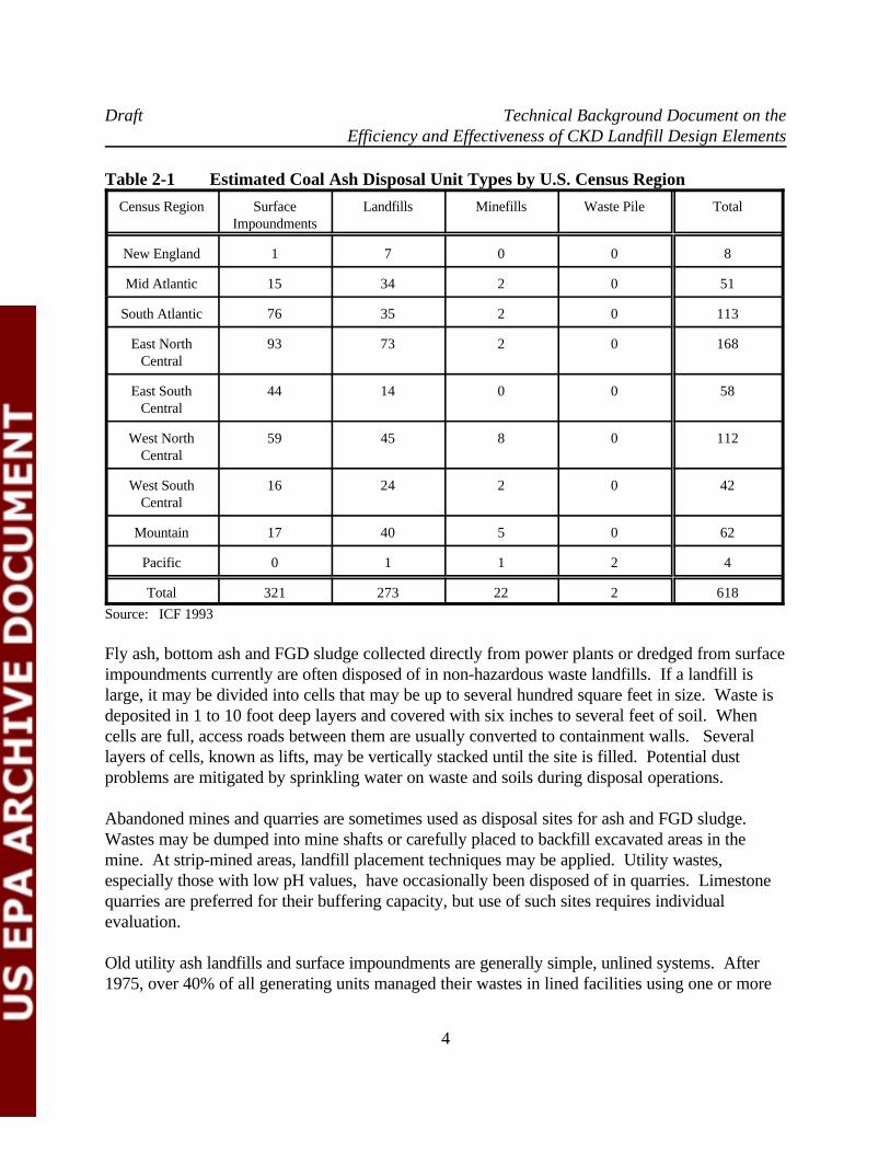
Coal combustion wastes may be managed in impoundments, landfills, mines and quarries or otherfacilities. As shown in Table 2-1, approximately 45% of all the coal ash disposal units in theUnited States are landfills. Surface impoundments or wet ponds allow the solids contained in coal ash slurries and sludges tosettle and accumulate at the bottom of the ponds. One pond or a series of sedimentation pondsmay be used to treat the wastes. Each pond may cover up to several hundred acres and initialdepths may range from 10 to 100 feet. The accumulated solids are often dredged and taken toalternative disposal sites such as landfills.
Draft Technical Background Document on theEfficiency and Effectiveness of CKD Landfill Design Elements
4
Table 2-1 Estimated Coal Ash Disposal Unit Types by U.S. Census Region
Census Region Surface Landfills Minefills Waste Pile TotalImpoundments
New England 1 7 0 0 8
Mid Atlantic 15 34 2 0 51
South Atlantic 76 35 2 0 113
East North 93 73 2 0 168Central
East South 44 14 0 0 58Central
West North 59 45 8 0 112Central
West South 16 24 2 0 42Central
Mountain 17 40 5 0 62
Pacific 0 1 1 2 4
Total 321 273 22 2 618
Source: ICF 1993
Fly ash, bottom ash and FGD sludge collected directly from power plants or dredged from surfaceimpoundments currently are often disposed of in non-hazardous waste landfills. If a landfill islarge, it may be divided into cells that may be up to several hundred square feet in size. Waste isdeposited in 1 to 10 foot deep layers and covered with six inches to several feet of soil. Whencells are full, access roads between them are usually converted to containment walls. Severallayers of cells, known as lifts, may be vertically stacked until the site is filled. Potential dustproblems are mitigated by sprinkling water on waste and soils during disposal operations.
Abandoned mines and quarries are sometimes used as disposal sites for ash and FGD sludge. Wastes may be dumped into mine shafts or carefully placed to backfill excavated areas in themine. At strip-mined areas, landfill placement techniques may be applied. Utility wastes,especially those with low pH values, have occasionally been disposed of in quarries. Limestonequarries are preferred for their buffering capacity, but use of such sites requires individualevaluation.
Old utility ash landfills and surface impoundments are generally simple, unlined systems. After1975, over 40% of all generating units managed their wastes in lined facilities using one or more
Draft Technical Background Document on theEfficiency and Effectiveness of CKD Landfill Design Elements
5
layers of low permeability clays or synthetic liners, or a combination of both. Fly ash has beenincorporated in some clay liners since it is cohesive and fairly impermeable when properlycompacted. However, variabilities in its chemical composition and changes in its permeability andsheer strength over time limit its use.
Besides the use of liners, waste management facilities may install leachate collection and ground-water monitoring systems, pre-treat wastes before disposal, and dewater the sludge to improveease of handling and obtain the consistency suitable for landfill disposal.
2.3 Physical Characteristics of Ash and CKD
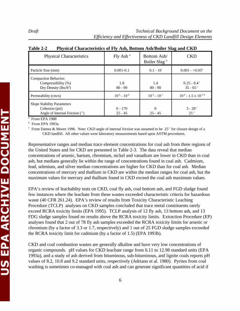
Representative ranges of values for the physical characteristics of coal combustion wastes (fly ash,and bottom ash/boiler slag), and waste CKD are presented in Table 2-2. A comparison of thesetwo types of wastes indicates that their geotechnical properties are generally similar. Particle sizedistributions are dependant on waste generation processes. However, most fly ash particles rangefrom 0.001 to 0.1 mm in diameter, and for CKD, about 55 per cent measures less than 0.03 mm(EPA 1993a). Pebble and smaller sized, uncalcined rock fragments of the raw materials used tomake cement form a minor component of CKD. Data from tests performed on CKD samplesused to design a final landfill cover (Dames & Moore 1996) indicate that CKD compressibilityand dry density values are lower than the overall ranges for ash and boiler slag wastes. Althoughthe ranges in permeability values for ash and CKD reflect the differences in grain sizes from site tosite, CKD permeabilities appear to be very similar to that of fly ash. Slope stability parametersused to evaluate final CKD landfill covers (Dames & Moore 1996) also fall within therepresentative range for fly ash. It is noted that wet FGD scrubber sludge consists primarily of0.001 to 0.05 mm sized particles, has a permeability of 10 to 10 cm/s, and an unconfined-6 -4
compressive strength ranging from 0 (wet) to 1600 (dry) psi.
2.4 Chemical Characteristics of Ash and CKD
The chemical composition of coal ash is related to the type of coal burned, pre-combustion coalpreparation and boiler operating conditions. The composition of CKD is also dependant on how itis generated, but significant variability is possible even between kilns with relatively minorprocessing differences (EPA 1993a).
Bulk constituents found in both coal ash and CKD (that is, constituents that exceed 0.05 per centby weight in the sampled material) are similar and include aluminum, calcium, iron, magnesium,potassium, silicon, sodium, and titanium. In addition, CKD bulk constituents include manganese,sulfur, and chloride (EPA 1993a). At individual ash disposal landfills, environmentally significantsulfur concentrations may be derived from co-disposal of pyrites (i.e., iron sulfide) with coal ash(EPA 1993b).
Draft Technical Background Document on theEfficiency and Effectiveness of CKD Landfill Design Elements
6
Table 2-2 Physical Characteristics of Fly Ash, Bottom Ash/Boiler Slag and CKD
Physical Characteristics Fly Ash Bottom Ash/ CKDa
Boiler Slag a
Particle Size (mm) 0.001-0.1 0.1 - 10 0.001 - >0.05b
Compaction Behavior: Compressibility (%) 1.8 1.4 0.25 - 0.4 Dry Density (lbs/ft ) 80 - 90 80 - 90 35 - 65 3
c
c
Permeability (cm/s) 10 - 10 10 - 10 10 - 1.5 x 10 -6 -4 -3 -1 -6 -3 b
Slope Stability Parameters Cohesion (psi) 0 - 170 0 3 - 28 Angle of Internal Friction (E) 25 - 45 25 - 45 25
c
c
From EPA 1988a
From EPA 1993ab
From Dames & Moore 1996. Note: CKD angle of internal friction was assumed to be 25E for closure design of ac
CKD landfill. All other values were laboratory measurements based upon ASTM procedures.
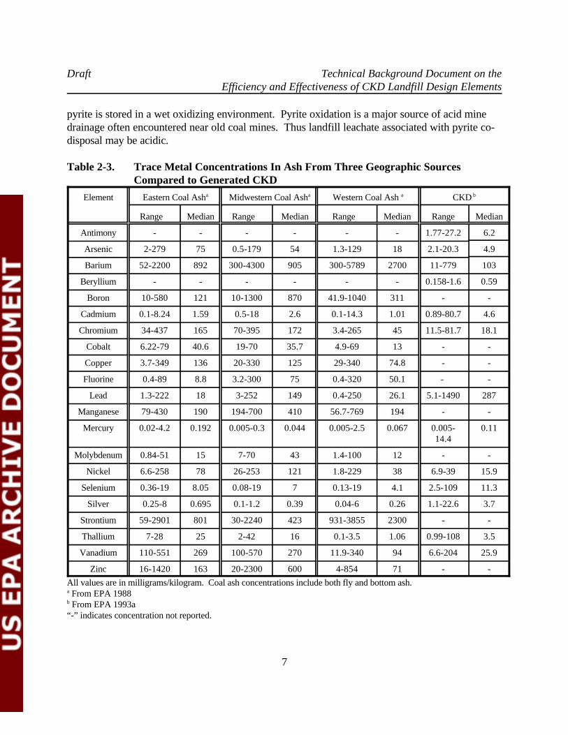
Representative ranges and median trace element concentrations for coal ash from three regions ofthe United States and for CKD are presented in Table 2-3. The data reveal that medianconcentrations of arsenic, barium, chromium, nickel and vanadium are lower in CKD than in coalash, but medians generally lie within the range of concentrations found in coal ash. Cadmium,lead, selenium, and silver median concentrations are higher for CKD than for coal ash. Medianconcentrations of mercury and thallium in CKD are within the median ranges for coal ash, but themaximum values for mercury and thallium found in CKD exceed the coal ash maximum values.
EPA’s review of leachablity tests on CKD, coal fly ash, coal bottom ash, and FGD sludge foundfew instances where the leachate from these wastes exceeded characteristic criteria for hazardouswaste (40 CFR 261.24). EPA’s review of results from Toxicity Characteristic LeachingProcedure (TCLP) analyses on CKD samples concluded that trace metal constituents rarelyexceed RCRA toxicity limits (EPA 1995). TCLP analysis of 12 fly ash, 13 bottom ash, and 13FDG sludge samples found no results above the RCRA toxicity limits. Extraction Procedure (EP)analyses found that 2 out of 78 fly ash samples exceeded the RCRA toxicity limits for arsenic orchromium (by a factor of 3.3 or 1.7, respectively) and 1 out of 25 FGD sludge samples exceededthe RCRA toxicity limit for cadmium (by a factor of 1.5) (EPA 1993b).
CKD and coal combustion wastes are generally alkaline and have very low concentrations oforganic compounds. pH values for CKD leachate range from 6.11 to 12.98 standard units (EPA1993a), and a study of ash derived from bituminous, sub-bituminous, and lignite coals reports pHvalues of 8.2, 10.8 and 9.2 standard units, respectively (Adriano et al. 1980). Pyrites from coalwashing is sometimes co-managed with coal ash and can generate significant quantities of acid if
Draft Technical Background Document on theEfficiency and Effectiveness of CKD Landfill Design Elements
7
pyrite is stored in a wet oxidizing environment. Pyrite oxidation is a major source of acid minedrainage often encountered near old coal mines. Thus landfill leachate associated with pyrite co-disposal may be acidic.
Table 2-3. Trace Metal Concentrations In Ash From Three Geographic SourcesCompared to Generated CKD
Element Eastern Coal Ash Midwestern Coal Ash Western Coal Ash CKDa a a b
Range Median Range Median Range Median Range Median
Antimony - - - - - - 1.77-27.2 6.2
Arsenic 2-279 75 0.5-179 54 1.3-129 18 2.1-20.3 4.9
Barium 52-2200 892 300-4300 905 300-5789 2700 11-779 103
Beryllium - - - - - - 0.158-1.6 0.59
Boron 10-580 121 10-1300 870 41.9-1040 311 - -
Cadmium 0.1-8.24 1.59 0.5-18 2.6 0.1-14.3 1.01 0.89-80.7 4.6
Chromium 34-437 165 70-395 172 3.4-265 45 11.5-81.7 18.1
Cobalt 6.22-79 40.6 19-70 35.7 4.9-69 13 - -
Copper 3.7-349 136 20-330 125 29-340 74.8 - -
Fluorine 0.4-89 8.8 3.2-300 75 0.4-320 50.1 - -
Lead 1.3-222 18 3-252 149 0.4-250 26.1 5.1-1490 287
Manganese 79-430 190 194-700 410 56.7-769 194 - -
Mercury 0.02-4.2 0.192 0.005-0.3 0.044 0.005-2.5 0.067 0.005- 0.1114.4
Molybdenum 0.84-51 15 7-70 43 1.4-100 12 - -
Nickel 6.6-258 78 26-253 121 1.8-229 38 6.9-39 15.9
Selenium 0.36-19 8.05 0.08-19 7 0.13-19 4.1 2.5-109 11.3
Silver 0.25-8 0.695 0.1-1.2 0.39 0.04-6 0.26 1.1-22.6 3.7
Strontium 59-2901 801 30-2240 423 931-3855 2300 - -
Thallium 7-28 25 2-42 16 0.1-3.5 1.06 0.99-108 3.5
Vanadium 110-551 269 100-570 270 11.9-340 94 6.6-204 25.9
Zinc 16-1420 163 20-2300 600 4-854 71 - -
All values are in milligrams/kilogram. Coal ash concentrations include both fly and bottom ash. From EPA 1988a
From EPA 1993ab
“-” indicates concentration not reported.
Draft Technical Background Document on theEfficiency and Effectiveness of CKD Landfill Design Elements
8
3.0 PROPOSED OPERATING CRITERIA AND DEFAULT TECHNICALSTANDARDS FOR CKD LANDFILL DESIGN
This chapter summarizes the default technical standards for CKD landfills currently underconsideration by EPA for inclusion in the proposed rule.
The proposed operating criteria include:
C Fugitive dust controls,C Temporary cap or daily cover,C Ground water monitoring and corrective action,C Storm water run-on/run-off controls surface water requirements, andC Landfill closure and post-closure requirements.
Standards for ground-water protection include:
C For units overlying karst aquifers, CKD landfills must have a composite bottom liner witha leachate collection system.
C For units in non-karst areas, the design must meet the performance standard. Theperformance standard will be no exceedance of ground-water protection standards (e.g.,Maximum Contaminant Levels (MCLs) or other health based numbers (HBNs)) at thepoint of compliance.
In addition, CKD must not be disposed below the natural water table. The proposed standardsare described in greater detail in the following sections.
3.1 Fugitive Dust Control
Uncontrolled fugitive dust emissions are known to be problematic at many CKD disposal sites dueto the fine grained nature of CKD. In EPA’s “Regulatory Determination on Cement Kiln Dust”(EPA 1995a), a total of 36 cases involving documented damage to air from CKD waste wereidentified. EPA is considering two standards for controlling fugitive dust at CKD waste unitsbased on RCRA Subtitle C regulations:
(1) Subpart N -- Landfills state that the facility owner must cover or otherwise manage thelandfill to control wind dispersal (40 CFR 264.301(j)).
(2) Subpart DD -- Containment Buildings state that the owner/operator must “takemeasures to control fugitive dust such that any openings exhibit no visible emissions” (40CFR 264.1101(c)(1)(iv)).
Draft Technical Background Document on theEfficiency and Effectiveness of CKD Landfill Design Elements
9
In addition good waste management practices should be used during collection of the waste at thecement plant and during transportation of the waste to the disposal site. Such practices mayinclude collecting the CKD in silos or hoppers, conditioning the waste (e.g., with water orpressing into pellets) before loading into trucks, covering the waste with tarps duringtransportation to the disposal site and implementing measures to minimize the potential for CKDwaste spillage. It is expected that RCRA Subtitle C, Subpart J -- Tank Systems standards (40CFR 264.190-199) for negative pressure environments, leak detection and containment controlswould not be appropriate for interim storage of CKD waste. Instead, the site operator would berequired to implement an effective dust control program tailored to site conditions in order tocost-effectively prevent fugitive dust emissions. At some locations, it may be found thatconditioning the CKD with water, compacting the CKD during disposal, and spraying the loadingarea, haul roads and disposal area with water, on an as-needed basis, could effectively controlfugitive dust emissions. Covering inactive areas of the landfill with soil or a dust suppressant maybe appropriate if longer term fugitive dust control methods are warranted.
3.2 Temporary Cap/Cover Material Requirements
A temporary or interim cover can protect buried CKD waste from erosion due to storm waterrun-off, mitigate infiltration of storm water into the CKD pile, and help control fugitive dustemissions. EPA is proposing that if the CKD waste is not conditioned (pelletized, wetted,slurried, solidified, etc.) prior to disposal, a daily cover will be required for but 60 meters (200feet) of the active face of the landfill. This is similar to RCRA Subtitle D standards which statethat the operator must cover the waste with at least 6 inches of earthen materials unlessdemonstrated that an alternative material or alternative thickness can control fugitive dustemissions with out presenting a threat to human health or the environment (40 CFR 258.21). It isrecognized that many of the reasons for requiring a soil cover at municipal landfills do not applyto CKD landfills (e.g., control of scavenging, disease vectors, fires, and odors).
3.3 Run-On/Run-Off Controls and Surface Water Requirements
To prevent off-site migration of CKD constituents during storm events, the CKD disposal unitmust be designed to collect and treat storm water run-off which is generated from the activeportions of the landfill. In addition, the unit must be protected from flooding due to storm waterrun-on from upgradient areas. As stated in EPA’s Regulatory Determination on CKD (EPA1995), existing authorities under the Clean Water Act are considered to be adequate to protectsurface waters. It is assumed that CKD rule-making standards will be similiar to the RCRASubtitle D standards for landfill run-on/run-off controls and surface water requirements (See 40CFR 258.26 and 258.27). These regulations require that Subtitle D landfills must be designed toaccommodate storm water run-off associated with the 24-hour storm which occurs with afrequency of once every 25 years (i.e., 25-year storm). These landfills must be designed to
Draft Technical Background Document on theEfficiency and Effectiveness of CKD Landfill Design Elements
10
prevent landfill slope failures or failure of the storm water run-off collection and treatment systemdue to the 25-year storm. Surface water run-off from active areas of a CKD landfill is likely tocontain heavy loads of suspended particles, a high pH, and CKD waste constituents. Storm waterrun-off treatment systems at CKD disposal sites would be required to obtain and operate under aNational Pollutant Discharge Elimination System (NPDES) permit if this water is expected to bedischarged to off-site surface waters (40 CFR 258.27 (a)). In addition, EPA is proposing thatSubtitle C location restrictions for 100-year flood plains (40 CFR 264.18 (b)) should be applied toCKD waste management units.
3.4 Bottom Liner Requirements for New or Laterally Expanding CKD Landfills
EPA’s proposed bottom liner standards for design and operation of new or laterally expandingCKD landfills include a performance standard and a technical design standard for CKD landfillslocated over karst aquifers. Because of the high potential for CKD landfill leakage to causeground-water degradation in karst aquifers, EPA considers the Subtitle D default technical designstandard to be appropriate for CKD landfills in karstic areas. In non-karstic areas, where risk toground-water resources are less, a performance-based landfill design is considered appropriate.
3.4.1 Default Technical Standard for Units in Karst Areas (Composite Liner and LeachateCollection System)
After evaluating the performance of a range of landfill design configurations, EPA concluded thatthe Subtitle D default design would be adequate to control releases to ground water from CKDlandfills located in karstic areas where there is a possibility of CKD leachate entering the aquifer ina relatively undiluted form. The default technical standards for RCRA Subtitle D landfills (i.e., 40CFR 258.40(a)(2)) specifies the installation of a composite bottom liner (i.e., 0.6 meters (2 feet)of soil with less than 10 cm/s permeability overlain by a flexible membrane liner) and a leachate-7
collection system (designed so that less than 30 cm (1 foot) of leachate covers the liner). Byminimizing net infiltration by means of a Subtitle D default landfill design, there will be acorresponding low potential for ground-water contamination. EPA’s modeling of the Subtitle Ddefault technical design predicted a leakage rate of 3 x 10 inches/year or less at eight different-6
climate regions in the United States (EPA 1997).
3.4.2 Performance-Based Design for Units in Non-Karstic Areas
The Agency considered a range of options for performance standards for CKD landfills. Theseoptions included (1) the “no significant release” performance standards (based on the industryproposal and the performance-based design standards for MSWLFs under Subtitle D) and (2) a“no release” performance standards based on the approach used under Subtitle C for hazardouswaste landfills. After evaluating a range of possible performance standards and considering the
Draft Technical Background Document on theEfficiency and Effectiveness of CKD Landfill Design Elements
11
need for a tailored and flexible approach for the protection of ground water, the Agency isproposing a performance-based design standard that is based on the RCRA Subtitle Dperformance standard found in 40 CFR 258.40(a)(1):
The design of a cement kiln dust landfill must ensure that there will be no exceedence ofEPA’s maximum contaminant levels (MCLs) for drinking water and/or other health basednumbers (HBNs) for arsenic, antimony, barium, beryllium, cadmium, chromium, lead,mercury, nickel, selenium, silver, and thallium in the uppermost aquifer at the relevantpoint of compliance (POC).
The relevant POC shall be no more than 150 meters (500 feet) from the wastemanagement unit boundary and shall be located on land owned by the owner of the cementkiln dust landfill.
The performance standard will be protective of human health and the environment because itensures that constituents of concern in ground water will be below MCLs/HBNs, and will besufficient to prevent releases beyond the facility boundary. Selection of the “no significantrelease” performance standard is consistent with EPA’s intent to develop tailored standards forCKD landfills that are protective of human health and the environment and will ensure flexibilityfor implementation by States, tribes, and municipalities. EPA’s evaluation of potential landfillsdesigns found that site-specific climate conditions are a critical factor in designing to thisproposed performance standard. Based on the results of EPA’s modeling of landfill designs, themost engineering controls (i.e., the Subtitle D technical default standard) are expected to berequired in cold climates with more than 1 meter (40 inches) of precipitation per year. Landfilldesigns with fewer engineering controls (i.e., a compacted CKD bottom and top layers, vegetatedcover, and no leachate collection) are expected to achieve the performance standard at non-karstic sites with about 25 cm (10 inches) or less of precipitation per year (EPA 1997).
3.5 Ground Water Monitoring and Corrective Action
EPA’s proposed ground-water monitoring regulations for CKD landfills use the same approach asthe RCRA Subtitle D landfill design performance standard (i.e., no exceedence of ground-waterprotection standards at the points of compliance (40 CFR 258.40(a)(1)) and Subtitle D ground-water monitoring regulations (40 CFR 258.50-258.55). Points of compliance used to enforcethese standards are typically monitoring wells at the unit’s property boundary or up to a point 150meters (500 feet) from the landfill. EPA is proposing that ground-water detection monitoringwould include analysis of pH, conductivity, total dissolved solids (TDS), potassium, chloride,sodium, and sulfate and assessment monitoring would only include toxic metals (i.e., no organiccompounds). Statistical techniques for identification of potential releases to ground water will bebased on methods specified in 40 CFR 258.53(g) and 40 CFR 264.97. Ground-water monitoring
Draft Technical Background Document on theEfficiency and Effectiveness of CKD Landfill Design Elements
12
requirements may be suspended if the owner can prove that there is no potential for migration ofhazardous constituents into the uppermost aquifer. The corrective action program for CKDlandfills will be based on the RCRA Subtitle D approach found at 40 CFR 258.56-58.
EPA is proposing that new, detailed site characterization standards should be used for CKDlandfills in karst areas including:
C Characterization of site hydrology (i.e., identification of: site hydraulic andgeologic features; subsurface strata; recharge and discharge conditions; variabilityin flow directions and rates; variability in flow system due to seasonal, tidal, andnearby human influences; and those additional conditions that render the locationhydraulically complex).
C Identification of the uppermost aquifer and aquifer hydraulically interconnectedbeneath and contiguous to the facility property, and evaluation of the potential forcontaminant migration into the aquifers.
C Use of a ground-water flow net (or equivalent hydrogeological model),constructed from data collected on a local scale, that identifies the rate anddirection of ground-water flow within the aquifers.
C Use of the ground-water flow net to identify the placement and position of ground-water monitoring wells to ensure compliance with the RCRA Subtitle D ground-water monitoring requirements.
3.6 Closure and Post-Closure Requirements
EPA’s proposed standards for landfill closure and post-closure requirements use the sameapproach as the RCRA Subtitle D standards (40 CFR 258.60-61). These regulations require that,in order to close a landfill, the owner must install a final cover system that is designed to minimizeinfiltration and erosion. The cover must have a permeability less than or equal to the bottom lineror natural subsoils or have a permeability no greater than 10 cm/sec, whichever is less. The-5
cover must minimize infiltration by using an infiltration layer that contains at least 18 inches ofearthen material. The cover must minimize erosion by using an erosion layer that contains at least6 inches of earthen material that is capable of sustaining native plant growth. An alternativelandfill final cover design may be approved as long as it provides an equivalent degree ofinfiltration and erosion protection. A 30-year post-closure monitoring period would be required.
Draft Technical Background Document on theEfficiency and Effectiveness of CKD Landfill Design Elements
13
4.0 COAL ASH LANDFILLS SELECTED FOR STUDY
4.1 Ash Landfill Identification and Screening Methodology
This section discusses how utility coal ash landfills were identified and screened for study in thisTBD. In a preparatory report for this TBD entitled “Identification of Candidate Landfills forFurther Study”, ten landfills were identified as having several of the landfill design/operationelements identified in Section 3 (SAIC 1997). Information was collected from the Utility DataInstitute’s (UDI) power statistic database for the year 1994 on utility coal ash generation ratesand disposal practices and from telephone conversations with state regulators in Pennsylvania,Texas and Colorado on the availability of landfill engineering designs and performance data forlandfills listed in the UDI database. A total of 32 utility fly ash landfills were identified inPennsylvania, Texas and Colorado from the UDI database. In addition, documentedenvironmental damages from coal ash landfills, as presented in EPA’s “Supplemental Analysis onPotential Risks to Human Health and the Environment from Large-Volume Coal CombustionWaste” (EPA 1993b), were used to screen candidate landfills for further study. From thisinformation, ten candidate landfills were recommended for consideration for further studyincluding seven landfills in Pennsylvania, two landfills in Texas, and one facility in Maryland.
4.2 Candidate Landfills Selected for Further Study
Of the ten candidate sites recommended for consideration in Section 4.1, EPA selected four of thePennsylvania facilities and the ash disposal site in Maryland for study. The Maryland site wassubsequently dropped from this study. It was found that since the 1980's, the State of Marylandhas exempted pozzolanic waste disposal (including coal ash) from regulatory oversight. As aresult, the State does not have any information on the waste disposal practices or landfill designfor this site.
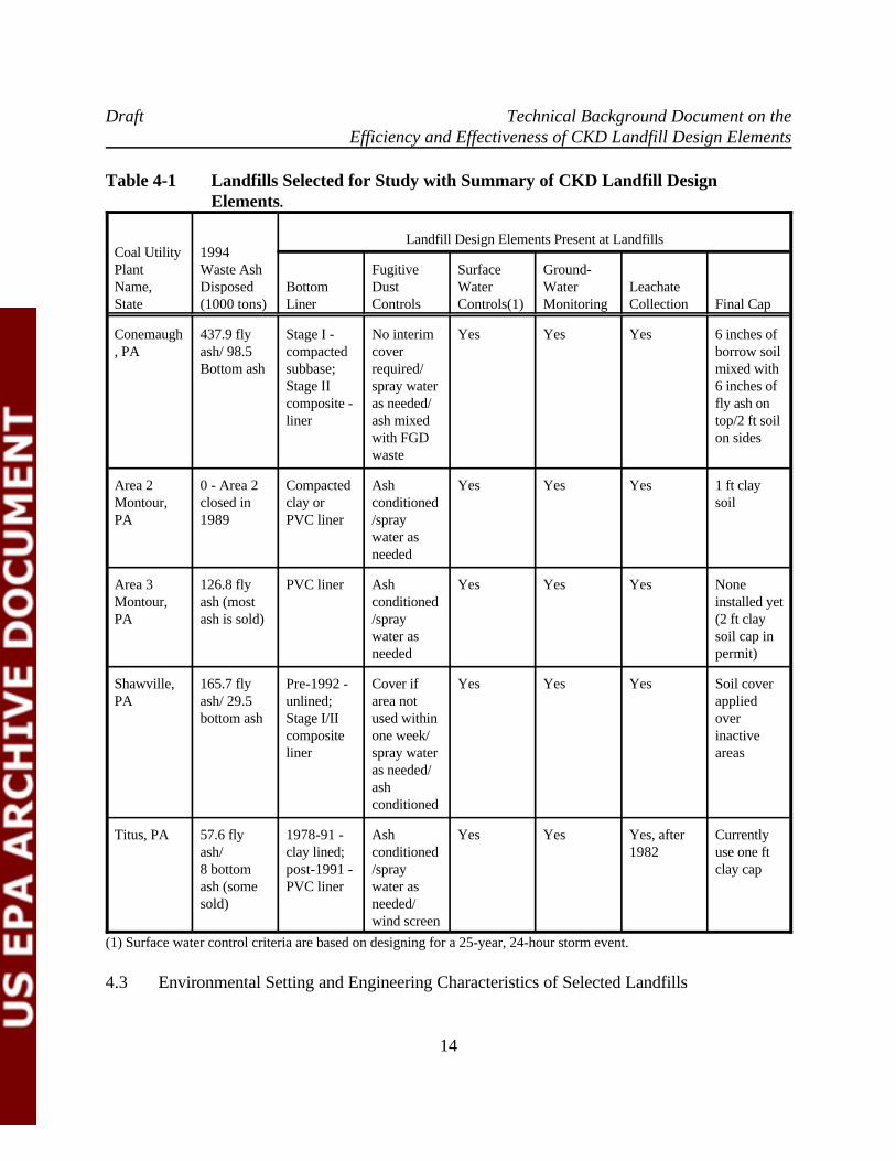
Regulatory files on waste disposal, landfill leachate/run-off treatment, and air emissions for thefour selected Pennsylvania facilities were reviewed in PDEP regional offices in April 1997. Table4-1 presents a summary of the proposed CKD landfill design elements found at the four facilitiesstudied in this TBD. Two ash landfills (i.e., Ash Storage Area 2 and Ash Storage Area 3) havebeen permitted at the Montour Steam Electric Station. At the other three Pennsylvania facilities(i.e., Conemaugh, Shawville, and Titus power plants), the ash landfills have been expanded inphases and have been issued several major and minor Solid Waste Permit Modifications over time.
Draft Technical Background Document on theEfficiency and Effectiveness of CKD Landfill Design Elements
14
Table 4-1 Landfills Selected for Study with Summary of CKD Landfill Design Elements.
Coal Utility 1994Plant Waste Ash Fugitive Surface Ground-Name, Disposed Bottom Dust Water Water LeachateState (1000 tons) Liner Controls Controls(1) Monitoring Collection Final Cap
Landfill Design Elements Present at Landfills
Conemaugh 437.9 fly Stage I - No interim Yes Yes Yes 6 inches of, PA ash/ 98.5 compacted cover borrow soil
Bottom ash subbase; required/ mixed withStage II spray water 6 inches ofcomposite - as needed/ fly ash onliner ash mixed top/2 ft soil
with FGD on sideswaste
Area 2 0 - Area 2 Compacted Ash Yes Yes Yes 1 ft clayMontour, closed in clay or conditioned soilPA 1989 PVC liner /spray
water asneeded
Area 3 126.8 fly PVC liner Ash Yes Yes Yes NoneMontour, ash (most conditioned installed yetPA ash is sold) /spray (2 ft clay
water as soil cap inneeded permit)
Shawville, 165.7 fly Pre-1992 - Cover if Yes Yes Yes Soil coverPA ash/ 29.5 unlined; area not applied
bottom ash Stage I/II used within overcomposite one week/ inactiveliner spray water areas
as needed/ashconditioned
Titus, PA 57.6 fly 1978-91 - Ash Yes Yes Yes, after Currentlyash/ clay lined; conditioned 1982 use one ft8 bottom post-1991 - /spray clay capash (some PVC liner water assold) needed/
wind screen
(1) Surface water control criteria are based on designing for a 25-year, 24-hour storm event.
4.3 Environmental Setting and Engineering Characteristics of Selected Landfills
Draft Technical Background Document on theEfficiency and Effectiveness of CKD Landfill Design Elements
15
The locations of the four selected landfill study sites are shown in Figure 1 (see Appendix A). Theclimate of Pennsylvania is considered to be of a humid, continental type. Average annualprecipitation from 1960-1990 at the four study sites ranges from about 40 inches at Montour,Shawville, and Titus to about 45 inches for Conemaugh. Precipitation is fairly evenly distributedthroughout the year. The greatest amounts of precipitation occur in the spring and summermonths, while February is the driest month with about 2 inches less than the wettest months(Sterner 1994). All four facilities are located in the Ridge and Valley Province at the northern endof the Appalachian Mountain system with Mesozoic- or Paleozoic-aged bedrock formationspresent at shallow depths. The engineering characteristics of the selected study sites aresummarized in the following subsections.
4.3.1 Conemaugh Ash Disposal Site
The Conemaugh Station is a steam electric generating station located on the Conemaugh River inWest Wheatfield Township, Indiana County, Pennsylvania. It first started operations in 1970 andcurrently has an electric generating capacity of 1700 megawatts (MW). It is owned by theConemaugh Owners Group which consists of nine utility corporations. Pennsylvania ElectricCompany (Penelec) was considered to be the plant operator until it was purchased in 1996 byGeneral Public Utilities (GPU) Genco. The ash landfill for the Conemaugh Plant has beenpermitted since 1974, is currently permitted to use 506 acres (including 72 acres for logisticalsupport) in a relatively small valley about 2 miles north of the plant and has a total permitteddisposal capacity of 82,000,000 cubic yards (including future Stage III) (see Figure 2). Thelandfill has been projected to have to capacity until 2023. The oldest portion of the landfill (StageI) is located in an former strip mine and is unlined except for a compacted soil subbase. Since1988, the Stage II portions of the landfill have been lined with a 50-mil PVC bottom liner (GAI1996).
The landfill accepts mining refuse from nearby deep coal mines, which support the ConemaughStation; coal ash from Conemaugh Station and Stewart Station, located about 20 miles away; andother nonhazardous, noncombustible wastes generated at the Conemaugh station. The facility’s1988 Solid Waste Disposal Permit requires deployment of dust controls (e.g., application of wateror covering with soil) on an as-needed basis, if fugitive dust is observed to be generated. However no daily/interim cover is used until the final grade is achieved at a final cover isconstructed. The 1988 permit requires a two-foot thick soil cover on the final sides of the landfilland specifies that the top two feet of waste consist of fly ash. A permit variance was given for thetop cover of the landfill to allow mixing 6 inches of soil with 6 inches of fly ash.
A leachate collection system has been installed through out the disposal site. Acid mine drainage,landfill leachate and storm water run-off are routed to an on-site treatment system forneutralization and removal of iron before discharge to an unnamed tributary of the Conemaugh
Draft Technical Background Document on theEfficiency and Effectiveness of CKD Landfill Design Elements
16
River. The landfill waste water treatment system was originally designed to treat up to 1000gallons/minute of leachate and storm water run-off. However, in the 1980's, this was found to beinsufficient. Upgrades to the treatment system were required in the late 1980's due to flow ratesabove the treatment system design, inadequate pond sludge removal, and exceedences of NPDESdischarge limits (Penelec and PaDER 1982 and 1984). Since then, this waste water has beenrouted to the Conemaugh Station for treatment along with other waste water including flue gasdesulfurization (FGD) wastes. Quarterly ground-water monitoring is performed, as a permitcondition, at the landfill.
4.3.2 Montour Ash Storage Areas 2 and 3
The Montour Steam Electric Station is located on the Chillisquaque Creek in Derry Township,Montour County, Pennsylvania. It first started producing electricity in 1972, currently has anelectric generating capacity of 1500 MW, and is owned by the Pennsylvania Power & LightCompany (PP&LC). Operations in Ash Storage Area 2 began in 1982 and lasted until 1989 whenash disposal activities began in Ash Storage Area 3 (see Figure 3). In 1982, fly ash wastemanagement practices changed from sluicing to Ash Basin 1 to pneumatically transporting fly ashto silos for temporary storage. The fly ash is then conditioned with water and either sold off-sitefor beneficial uses or disposed of on-site. Montour is able to sell most of the fly and bottom ashthat is generated, primarily as light weight construction fill. Ash Storage Area 2 is permitted tocover 34 acres and is lined either with 20-mil PVC (where depth to ground water is less than 2feet) or with two feet of clay soil with a maximum permeability of 10 cm/s. Ash Storage Area 3-7
is permitted to cover 64 acres and is underlain by a 30-mil PVC bottom liner.
The conditioned fly ash is compacted to a minimum of 90 percent of Standard Proctor (ASTMD698) maximum density with a smooth wheel vibratory roller during disposal. Fly ash surfacesthat are completed but not at final grade are sprayed with water or a dust control agent orcovered with bottom ash if the ash surface begins to dust (PP&LC 1981). Permit conditionsrequire a one-foot thick final clay cover for Ash Storage Area 2 and a two-foot thick final claycover for Ash Storage Area 3. Storm water run-off and landfill leachate is collected in surgeponds adjacent to the landfills, routed to the plant’s Miscellaneous Plant Waste Basin fortreatment with other plant waste waters and discharged under a NPDES permit. Ground-watermonitoring has identified some evidence of downgradient contamination, although backgroundconcentrations of these constituents exceed drinking water standards (EPA 1993b).
4.3.3 Shawville Ash Disposal Site
The Shawville Station is a steam electric generating station located on the West Branch of theSusquehanna River in Bradford Township, Clearfield County, Pennsylvania. It began producingenergy in 1954, has a generating capacity of 625 MW, and was owned and operated by Penelec

Draft Technical Background Document on theEfficiency and Effectiveness of CKD Landfill Design Elements
17
until purchased in 1996 by GPU Genco. The ash disposal site is located about 0.75 mile from theShawville Station and has been used since the 1960's (see Figure 4). The initial solid wastedisposal permit application for this site was rejected in the 1970's due to the presence of acid minedrainage upgradient of the site and the presence of acidic springs underneath the landfill. Under aConsent Order and Agreement, a closure plan for the disposal site was submitted in 1984 withrevisions in 1988, 1989, and 1992. Unsuccessful attempts were made to identify and permit analternative ash disposal site until the late 1980's, when PDEP agreed to construction of a linedlandfill over the old landfill. The newer portion of the landfill (Phase I) was issued a Solid WastePermit in June 1992 and was allowed to built over the old unlined disposal site, provided that thesite collects and treats the landfill leachate and acid mine drainage generated at the site. A majorpermit modification was issued in June 1993 to allow expansion of Phase II under the Phase Ipermit. Phase III and IV were scheduled to be constructed beginning in 1997 and will use a ClassI liner system based on two liners (i.e., a high density polyethylene (HDPE) liner will be installedbelow the leachate detection system -- not low permeability soil as was used for the Phase I/IIdesign) (GAI 1995).
The permitted disposal area consists of 120 acres including 15 acres for the closed disposal area,50 acres for the active disposal area, and 55 acres for support activities. The permitted landfillwill add an addition 90 feet of ash to the old landfill over an 18-year design life and will provideabout 3.39 million cubic yards of disposal capacity. Approximately 217,000 tons of waste peryear is disposed at the site and is comprised of fly ash (74%), bottom ash (18%), pyrites (8%) andminor quantities of miscellaneous, noncombustible solid waste. The bottom liner designs of PhaseI and later portions of the landfill are based upon using 50 mil HPDE liners with both leachatecollection and detection systems. Ash is delivered to the site in a wet state, compacted duringdisposal and covered with soil on a weekly basis. The landfill has been designed to accommodaterun-on/run-off from the 25 year storm. Storm water run-off and leachate is routed to a treatmentlagoon and discharged under a NPDES permit (LR Kimball 1992). Quarterly ground-watermonitoring is performed, as a permit condition, at the landfill.
4.3.4 Beagle Club Ash Disposal Site/Titus Generating Station
The Titus Generating Station is a steam electric generating plant located on the Schuylkill River inCumru Township, Berks County, Pennsylvania. It began producing energy in 1951, has agenerating capacity of 240 MW, and is operated by Metropolitan Edison Company (Met-Ed)/GPU Genco. The Beagle Club Ash Disposal Site is located about 1 mile south of the City ofReading, adjacent to Highway 422, and immediately across the Schuylkill River from the TitusGenerating Station (see Figure 5). Disposal operations at the Beagle Club Ash Disposal Sitebegan when it was permitted as a new ash disposal site in 1978. Major permit modifications wereissued to the facility in 1984 to construct a leachate collection system under new portions of thefacility and to install leachate/run-off treatment ponds and in 1991 to install a 50-mil PVC bottom
Draft Technical Background Document on theEfficiency and Effectiveness of CKD Landfill Design Elements
18
liner under new portions of the facility. Because the 1984 permit prohibited new ash disposalover the old ash fill with out leachate collection, the pre-1984 ash landfill was excavated,stockpiled and then reburied. A leachate collection system was installed under the entire landfill. A minimum 2-foot-thick native clay layer is present under 9 acres of the landfill associated withpre-1991 ash disposal. Since 1991, a 50-mil-thick PVC bottom liner has been used for theremaining 10.7 acres of this landfill. An additional 18 acres has been permitted to provide supportfor the disposal area including leachate/run-off pond system, soil stockpiles and access roads(CEC 1992).
The Titus Generating Station produces about 44,000 tons per year of fly ash (77%), bottom ash(18%) and sedimentation pond ash (5%) (Gilbert/Commonwealth 1989). Some of the fly andbottom ash is used off-site for beneficial purposes however, most of the ash is disposed of at theBeagle Club Ash Disposal Site. As of January 1994, approximately 452 acre-feet of storagecapacity was calculated to be available, which was expected to provide sufficient capacity until theyear 2008.
The fly ash generated at the station is collected in hoppers, conditioned with water, trucked to thedisposal site, spread in one foot lifts and compacted. Sludge from an ash sedimentation pondassociated with the fly ash loading area and bottom ash is periodically removed and disposed atthe disposal facility. Fly ash surfaces that are completed but not at final grade are sprayed withwater or covered with bottom ash if the ash surface begins to dust. Spraying with dust controlagents may be used when ash would be exposed for extended periods (e.g. for station outages). Because of the concern for dusting due to the nearby Highway 422, wind screens wereconstructed after 1991 to mitigate this hazard. Portions of the landfill, which have been built upto the final grade, have been capped with a one-foot-thick clay layer (maximum permeability is 10 cm/s) (Gilbert/Commonwealth 1994). Landfill leachate and dirty storm run-off are collected-7
in ponds adjacent to the landfill and discharged under a NPDES permit to the Schuylkill River. Based on analytical results to date, no treatment has been required for this water. Ground-watermonitoring has identified evidence of leakage from the landfill including total dissolved solids(TDS) and sulfate in exceedence of secondary drinking water standards.
Draft Technical Background Document on theEfficiency and Effectiveness of CKD Landfill Design Elements
19
5.0 EVALUATION OF PROPOSED LANDFILL DESIGN ELEMENTS
Data on the four utility ash sites selected by EPA for study in this TBD were collected fromreview of regulatory files, conversations with PDEP officials, and from publicly availabledocuments. Note that information was gathered on both of the landfills (Ash Storage Areas 2 and3) present at the Montour Steam Electric Station. The expected performance of the proposedCKD landfill designs described in Section 3 are evaluated in this section using data on landfilldesigns and operations as implemented at the four coal utility plants. The following subsectionsevaluate the performance of fugitive dust controls (Section 5.1), temporary covers (Section 5.2),ground-water monitoring programs (Section 5.3), storm water run-on/run-off controls (Section5.4), composite bottom liner designs (Section 5.5), alternative bottom liner designs (Section 5.6),and closure and post-closure measures (Section 5.7) used at the fly ash landfills.
5.1 Fugitive Dust Controls
5.1.1 Fugitive Dust Control Technologies Applied At Fly Ash Landfills
The solid waste permits for each of the coal ash landfill sites require that the site control fugitivedust emissions. Fugitive dust control technologies being used at these sites range from sprayingdisposal area and roads with water on an as needed basis (e.g., at the Conemaugh landfill) tospraying with water as needed, compacting ash conditioned with water during disposal, andinstalling wind screens (e.g., at the Titus/Beagle Club landfill). There are no ashcompaction/placement requirements for the Conemaugh site except for the application/mixing ofFGD waste uniformly through out the landfill in layers less than 2 feet thick. The Montour andShawville ash disposal sites compact ash conditioned with water and spray water on unpaved haulroads and exposed ash surfaces as needed. At the Montour site, a vacuum truck is present on-siteto clean up loose ash from paved portion’s of Montour’s haul road. At the Shawville site, a streetsweeper is used to clean up the yard around the ash loading area. Operations at these landfillstypically focus on disposing ash in one foot lifts in a limited active area of the landfill until a benchis completed and a new bench is started. Landfill benches typically have a top about 3 m (10 feet)wide that slopes slightly (e.g., 3-5°) towards the landfill and are separated from each other by avertical distance of about 6 m (20 feet).
5.1.2 Effectiveness in Controlling Fugitive Dust Emissions
The effectiveness of the fugitive dust control programs described in Section 5.1.1 for the fivelandfills are summarized in Table 5-1. The fugitive dust control programs at the Conemaugh,Montour and Shawville sites appear to be effective in mitigating fugitive dust emissions (pers.com. John Hamilton, PDEP 1997 and Mick Planinsek, PDEP 1997). However, during publicreview of a permit modification to expand the Montour Ash Storage Area 2, the Derry Township
Draft Technical Background Document on theEfficiency and Effectiveness of CKD Landfill Design Elements
20
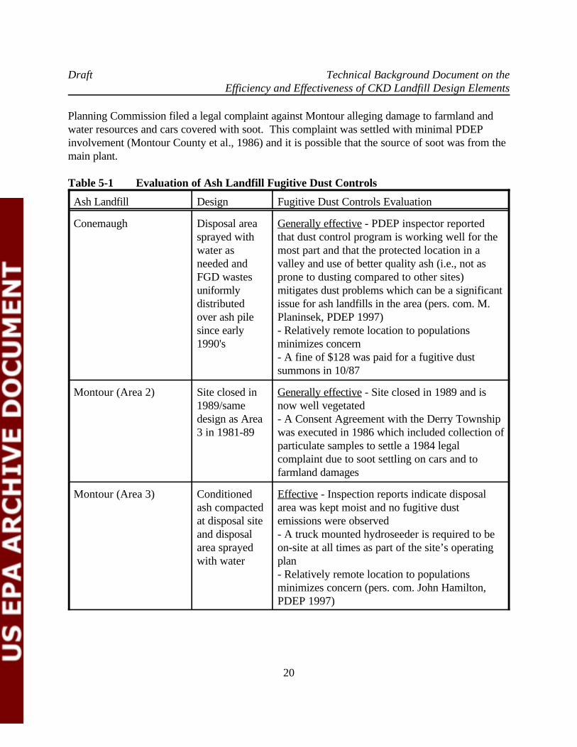
Planning Commission filed a legal complaint against Montour alleging damage to farmland andwater resources and cars covered with soot. This complaint was settled with minimal PDEPinvolvement (Montour County et al., 1986) and it is possible that the source of soot was from themain plant.
Table 5-1 Evaluation of Ash Landfill Fugitive Dust Controls
Ash Landfill Design Fugitive Dust Controls Evaluation
Conemaugh Disposal area Generally effective - PDEP inspector reportedsprayed with that dust control program is working well for thewater as most part and that the protected location in aneeded and valley and use of better quality ash (i.e., not asFGD wastes prone to dusting compared to other sites)uniformly mitigates dust problems which can be a significantdistributed issue for ash landfills in the area (pers. com. M.over ash pile Planinsek, PDEP 1997)since early - Relatively remote location to populations1990's minimizes concern
- A fine of $128 was paid for a fugitive dustsummons in 10/87
Montour (Area 2) Site closed in Generally effective - Site closed in 1989 and is1989/same now well vegetateddesign as Area - A Consent Agreement with the Derry Township3 in 1981-89 was executed in 1986 which included collection of
particulate samples to settle a 1984 legalcomplaint due to soot settling on cars and tofarmland damages
Montour (Area 3) Conditioned Effective - Inspection reports indicate disposalash compacted area was kept moist and no fugitive dustat disposal site emissions were observedand disposal - A truck mounted hydroseeder is required to bearea sprayed on-site at all times as part of the site’s operatingwith water plan
- Relatively remote location to populationsminimizes concern (pers. com. John Hamilton,PDEP 1997)
Draft Technical Background Document on theEfficiency and Effectiveness of CKD Landfill Design Elements
Ash Landfill Design Fugitive Dust Controls Evaluation
21
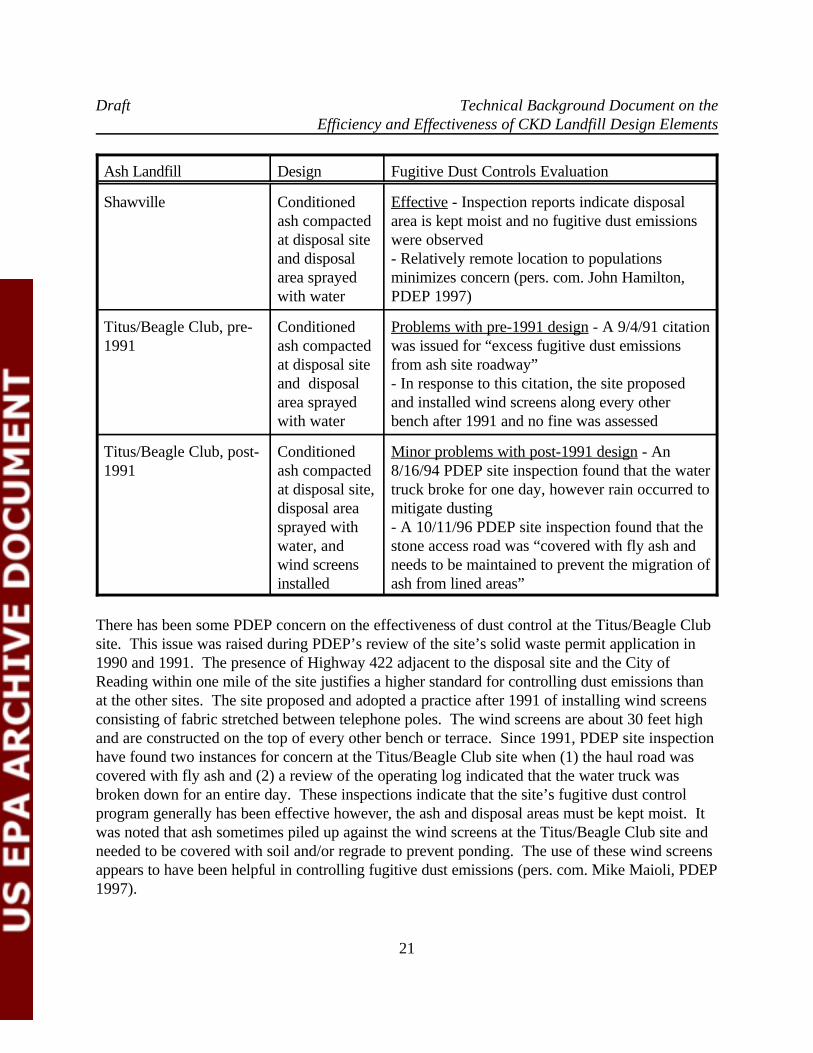
Shawville Conditioned Effective - Inspection reports indicate disposalash compacted area is kept moist and no fugitive dust emissionsat disposal site were observedand disposal - Relatively remote location to populationsarea sprayed minimizes concern (pers. com. John Hamilton,with water PDEP 1997)
Titus/Beagle Club, pre- Conditioned Problems with pre-1991 design - A 9/4/91 citation1991 ash compacted was issued for “excess fugitive dust emissions
at disposal site from ash site roadway”and disposal - In response to this citation, the site proposedarea sprayed and installed wind screens along every otherwith water bench after 1991 and no fine was assessed
Titus/Beagle Club, post- Conditioned Minor problems with post-1991 design - An1991 ash compacted 8/16/94 PDEP site inspection found that the water
at disposal site, truck broke for one day, however rain occurred todisposal area mitigate dusting sprayed with - A 10/11/96 PDEP site inspection found that thewater, and stone access road was “covered with fly ash andwind screens needs to be maintained to prevent the migration ofinstalled ash from lined areas”
There has been some PDEP concern on the effectiveness of dust control at the Titus/Beagle Clubsite. This issue was raised during PDEP’s review of the site’s solid waste permit application in1990 and 1991. The presence of Highway 422 adjacent to the disposal site and the City ofReading within one mile of the site justifies a higher standard for controlling dust emissions thanat the other sites. The site proposed and adopted a practice after 1991 of installing wind screensconsisting of fabric stretched between telephone poles. The wind screens are about 30 feet highand are constructed on the top of every other bench or terrace. Since 1991, PDEP site inspectionhave found two instances for concern at the Titus/Beagle Club site when (1) the haul road wascovered with fly ash and (2) a review of the operating log indicated that the water truck wasbroken down for an entire day. These inspections indicate that the site’s fugitive dust controlprogram generally has been effective however, the ash and disposal areas must be kept moist. Itwas noted that ash sometimes piled up against the wind screens at the Titus/Beagle Club site andneeded to be covered with soil and/or regrade to prevent ponding. The use of these wind screensappears to have been helpful in controlling fugitive dust emissions (pers. com. Mike Maioli, PDEP1997).
Draft Technical Background Document on theEfficiency and Effectiveness of CKD Landfill Design Elements
22
5.2 Temporary Cap or Daily Cover
5.2.1 Summary of Temporary Cap or Daily Cover Technologies Used At Fly Ash Landfills
As a permit condition, the Shawville site is required to install a temporary cover (i.e., soil orbottom ash) on ash surfaces that are expected to be inactive for a week more. None of the othersites are required to install temporary covers unless unprotected ash surfaces are exposed for sixmonths or more (Section 288.233 of Pennsylvania Residual Waste Regulations). However, theymay elect to install a temporary cover as an alternative to spraying with water as needed. As apermit condition, the Montour Ash Storage Area 3 and Shawville landfills are required to inspectthe landfill cover and erosion and sediment control structures on a weekly basis and/or after stormevents. At each of the sites, the ash waste is typically accumulated in benches until the final gradeis achieved and then a final cover is installed soon thereafter. At the Titus/Beagle Club site, the1989 permit application indicates that bottom ash or dust control agents may be applied when theash would be exposed for extended periods (e.g. during generating station outages). Very littleash is currently being disposed of at the Montour plant; Ash Storage Area 2 has been closed witha one-foot thick clay cap and no final cover has been installed at Ash Storage Area 3. Themaximum final landfill slopes will be 2 horizontal to 1 vertical (2:1) at the Conemaugh andShawville sites, 2.5:1 at the Titus/Beagle Club site, and 3:1 at the two Montour sites. At each ofthese sites, the top of the benches are slightly sloped back towards the landfill (e.g., 3-5%) tocollect surface water run-off.
5.2.2 Effectiveness of Covers Installed Prior to Site Closure
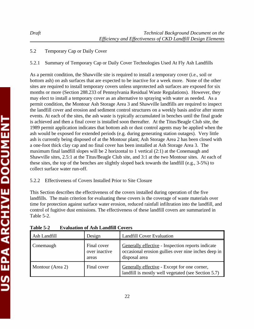
This Section describes the effectiveness of the covers installed during operation of the fivelandfills. The main criterion for evaluating these covers is the coverage of waste materials overtime for protection against surface water erosion, reduced rainfall infiltration into the landfill, andcontrol of fugitive dust emissions. The effectiveness of these landfill covers are summarized inTable 5-2.
Table 5-2 Evaluation of Ash Landfill Covers
Ash Landfill Design Landfill Cover Evaluation
Conemaugh Final cover Generally effective - Inspection reports indicateover inactive occasional erosion gullies over nine inches deep inareas disposal area
Montour (Area 2) Final cover Generally effective - Except for one corner,landfill is mostly well vegetated (see Section 5.7)

Draft Technical Background Document on theEfficiency and Effectiveness of CKD Landfill Design Elements
Ash Landfill Design Landfill Cover Evaluation
23
Montour (Area 3) Fix erosion Generally effective - No cover installed becausegullies on an as only very small quantities of ash are beingneeded basis disposed of
- Inspection reports indicate occasional erosiongullies over nine inches deep in disposal area
Shawville Final cover Generally effective - Inspection reports indicateover inactive occasional erosion gullies over nine inches deep inareas and f ix disposal areaerosion gullieson an asneeded basis
Titus Final cover Generally effective - Inspection reports indicateover inactive occasional erosion gullies over nine inches deep inareas and fix disposal areaerosion gullieson an asneeded basis
As discussed in Section 5.2.1, temporary or interim landfill covers appear to be rarely used at thecoal ash landfills studied in this TBD. Instead, a final cover is typically installed soon after thewaste has accumulated to the final grade and disposal activities have shifted to new area of thelandfill.
Gully erosion at the landfill or along the haul road appears to be a perennial issue at all of thestudy sites. Until final covers become vegetated they appear to be susceptible to erosion. PDEPsite inspections at all of these facilities have noted some gullies deeper than 9 inches which is outof compliance with state residual waste regulations (Chapter 288.242 (a)(c)). At the Titus/BeagleClub site, it was noted that gullies (as deep as 2 feet deep) were backfilled with gravel, but newgullies often formed adjacent to the old gullies which have been repaired by backfilling withgravel. In addition, ash and soil which accumulated near the wind screen occasionally causedwater to pond on top of the landfill and required periodic repair to restore proper drainage. Untilthe final slopes are densely vegetated, these coal ash landfills appear to be at risk from erosion. The soil covers installed at the coal ash landfills require continued monitoring and maintenanceparticularly after large storm events.
There appears to be a trade off between steep landfill side slopes which are prone to some erosionand landfills which cover a large area. In the long run it may be better to repair erosion gullies on
Draft Technical Background Document on theEfficiency and Effectiveness of CKD Landfill Design Elements
24
landfill slopes until it becomes vegetated than to design landfills which cover and impact a largerarea. Therefore, the cover designs were deemed to be effective provided ongoing monitoring andmaintenance is performed until the cover is densely vegetated and protected from erosion hazards.
5.3 Ground-Water Monitoring
5.3.1 Summary of Ground-Water Monitoring Practices at Fly Ash Landfills
All of the studied coal ash landfill sites have implemented quarterly ground-water programs incompliance with their landfill permit requirements. At each facility a number of monitoring wellsare located both upgradient and downgradient of the permitted landfill. At the Montour,Shawville and Titus/Beagle Club disposal sites, all of the downgradient monitoring wells arelocated within 140 meters (450 feet) of the downgradient edge of the landfill disposal area. However, at Conemaugh the downgradient wells were placed at a location projected to be nearthe edge of the landfill in the year 2028, which is over 610 meters (2000 feet) from the currentdisposal area.
The ground-water systems beneath the Conemaugh and Shawville landfills have been impacted bypre-existing acid mine drainage, complicating interpretation of the ground water monitoringinformation. The Stage I area of the Conemaugh landfill is located over a former coal strip mine. A coal strip mine is located upgradient of the Shawville landfill and the run and springsdowngradient of the landfill were known to be impacted by acidic ground water since 1957 (GAI1995). Poor-quality ground water, greatly exceeding drinking water standards for TDS andsulfate, is encountered at the Montour site due to oxidation of naturally occurring pyrite in theshale bedrock (PP&LC 1987).
Both the Conemaugh and Shawville sites are currently implementing a detection monitoringprogram. The Montour landfills have implemented ground-water investigations due to elevatedconcentrations of waste constituent parameters in the downgradient wells relative to theupgradient wells. The Titus/Beagle Club facility has not changed its ground water monitoringprogram since 1985 (when the monitoring program was improved to use 4-inch diameter wellsand a well which was screen in coal refuse was plugged) even though some ground-waterdegradation from landfill operations were documented as early as 1989.
The detection monitoring program for the Conemaugh and Shawville sites compare ground-watermonitoring results with calculated potential degradation indication levels (PDIL) to evaluate if alandfill release has occurred (GAI 1995 and 1996). PDILs were calculated using the followingformula:
Draft Technical Background Document on theEfficiency and Effectiveness of CKD Landfill Design Elements
25
PDIL = M + (S * K) (Equation 1)
where: M = the background mean concentration,S = standard deviation for the background wells, andK = statistical number depending on the number of samples collected, range of
sampling dates, and percentage of censored values (K was noted to bealways over 5) (GAI 1996).
For example, the background data for pH in Conemaugh’s well MW-12 consisted of 8 dissolvediron measurements with a mean of 4226.3 ug/L, a standard deviation of 2379.3 and a K multiplierof 5.811. The resulting PDIL is calculated to be 18,052.41 ug/L. No indication of potentialground water contamination was found in the dissolved iron data according to this method unlessa downgradient dissolved iron measurement is greater than 18,052.41 ug/L. No PDILexceedences were noted for any monitored constituents or parameters in the recent Conemaughand Shawville ground water assessment reports (GAI 1995 and 1996).
PDEP was notified of potential ground-water degradation at the two Montour disposal areaswhen trend analysis of the monitoring well data indicated rising downgradient concentrations ofsulfate, calcium and other constituents in downgradient wells relative to background wells. Elevated downgradient constituents included lab conductivity for the Montour Area 3 and iron, magnesium, manganese, nickel and zinc for the Montour Area 2. The site’s criteria for identifyinga potential release based on the degree of concentration increases were not specified in theground-water compliance reports (PP&LC 1987 and 1997). In 1989, PDEP began to beconcerned about potential ground water quality degradation near the Titus Beagle Club site, whenit was observed that from 1985 to 1988, the concentrations of specific conductance and sulfatesrose 300 umhos/cm and 20-200 mg/L, respectively, in downgradient wells relative that of thebackground well (PaDER 1989).
5.3.2 Effectiveness of Ground Water Monitoring Systems in Detecting Releases From Fly AshLandfills
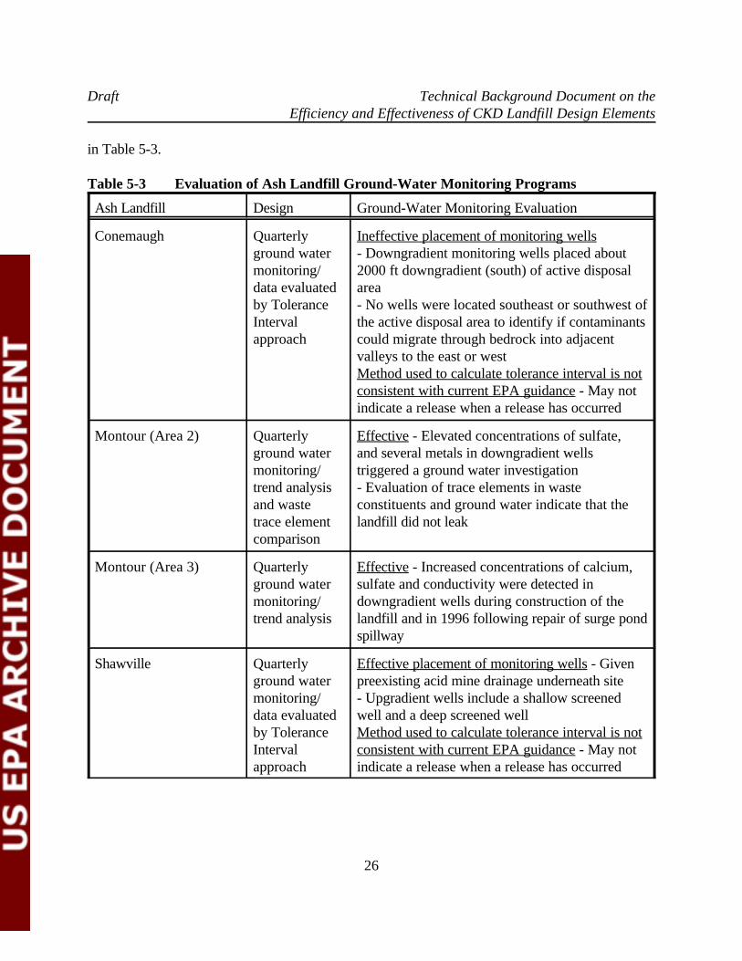
In general, the effectiveness of a ground-water monitoring system can be judged considering thefollowing three components: (1) its design (considering the site-specific hydrogeologic setting andthe waste characteristics), (2) the constituents being monitored, and (3) statistical techniques usedto evaluate the data generated by the system. Evaluation of the monitoring system designincludes assessment of the well placement, the length and position of the screened interval, wellconstruction materials, and sources of contamination. Evaluation of the statistical methodologyneeds to consider the regulatory objectives, the regulatory requirements, and current guidance onmethods for the statistical analysis of ground-water monitoring data. The effectiveness of theground-water monitoring systems described in Section 5.3.1 for the five landfills are summarized
Draft Technical Background Document on theEfficiency and Effectiveness of CKD Landfill Design Elements
26
in Table 5-3.
Table 5-3 Evaluation of Ash Landfill Ground-Water Monitoring Programs
Ash Landfill Design Ground-Water Monitoring Evaluation
Conemaugh Quarterly Ineffective placement of monitoring wells ground water - Downgradient monitoring wells placed aboutmonitoring/ 2000 ft downgradient (south) of active disposaldata evaluated area by Tolerance - No wells were located southeast or southwest ofInterval the active disposal area to identify if contaminantsapproach could migrate through bedrock into adjacent
valleys to the east or westMethod used to calculate tolerance interval is notconsistent with current EPA guidance - May notindicate a release when a release has occurred
Montour (Area 2) Quarterly Effective - Elevated concentrations of sulfate, ground water and several metals in downgradient wellsmonitoring/ triggered a ground water investigationtrend analysis - Evaluation of trace elements in wasteand waste constituents and ground water indicate that thetrace element landfill did not leak comparison
Montour (Area 3) Quarterly Effective - Increased concentrations of calcium,ground water sulfate and conductivity were detected inmonitoring/ downgradient wells during construction of thetrend analysis landfill and in 1996 following repair of surge pond
spillway
Shawville Quarterly Effective placement of monitoring wells - Givenground water preexisting acid mine drainage underneath sitemonitoring/ - Upgradient wells include a shallow screeneddata evaluated well and a deep screened wellby Tolerance Method used to calculate tolerance interval is notInterval consistent with current EPA guidance - May notapproach indicate a release when a release has occurred
Draft Technical Background Document on theEfficiency and Effectiveness of CKD Landfill Design Elements
Ash Landfill Design Ground-Water Monitoring Evaluation
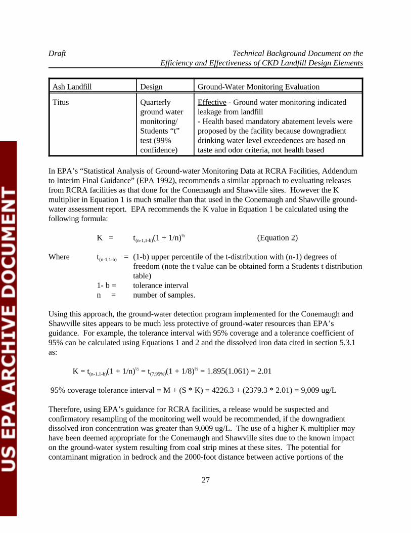
27
Titus Quarterly Effective - Ground water monitoring indicatedground water leakage from landfillmonitoring/ - Health based mandatory abatement levels wereStudents “t” proposed by the facility because downgradienttest (99% drinking water level exceedences are based onconfidence) taste and odor criteria, not health based
In EPA’s “Statistical Analysis of Ground-water Monitoring Data at RCRA Facilities, Addendumto Interim Final Guidance” (EPA 1992), recommends a similar approach to evaluating releasesfrom RCRA facilities as that done for the Conemaugh and Shawville sites. However the Kmultiplier in Equation 1 is much smaller than that used in the Conemaugh and Shawville ground-water assessment report. EPA recommends the K value in Equation 1 be calculated using thefollowing formula:
K = t (1 + 1/n) (Equation 2)(n-1,1-b)½
Where t = (1-b) upper percentile of the t-distribution with (n-1) degrees of(n-1,1-b)
freedom (note the t value can be obtained form a Students t distributiontable)
1- b = tolerance interval n = number of samples.
Using this approach, the ground-water detection program implemented for the Conemaugh andShawville sites appears to be much less protective of ground-water resources than EPA’sguidance. For example, the tolerance interval with 95% coverage and a tolerance coefficient of95% can be calculated using Equations 1 and 2 and the dissolved iron data cited in section 5.3.1as:
K = t (1 + 1/n) = t (1 + 1/8) = 1.895(1.061) = 2.01 (n-1,1-b) (7,95%)½ ½
95% coverage tolerance interval = M + (S * K) = 4226.3 + (2379.3 * 2.01) = 9,009 ug/L
Therefore, using EPA’s guidance for RCRA facilities, a release would be suspected andconfirmatory resampling of the monitoring well would be recommended, if the downgradientdissolved iron concentration was greater than 9,009 ug/L. The use of a higher K multiplier mayhave been deemed appropriate for the Conemaugh and Shawville sites due to the known impacton the ground-water system resulting from coal strip mines at these sites. The potential forcontaminant migration in bedrock and the 2000-foot distance between active portions of the
Draft Technical Background Document on theEfficiency and Effectiveness of CKD Landfill Design Elements
28
Conemaugh landfill and the nearest downgradient monitoring wells have been raised as points ofconcern by the PDEP (PDEP 1996). It is noted than the proposed CKD standard for locatingmonitoring is within 150 meters (500 feet) from the landfill.
Potential ground-water degradation downgradient of the Montour Ash Storage Area 2 wasidentified within one year following commencement of ash disposal activities in 1981. Traceelement analysis of the elevated constituents indicated that the elevated concentrations in thedowngradient wells was due to oxidation of pyrite in the native bedrock materials and not fromwaste leachate. Earthwork activities during construction of the landfill reportedly increase therate of pyrite oxidation in native materials resulting in increased concentrations of sulfate andTDS. Elevated concentrations of indicator trace elements such as lithium, selenium, chromiumand boron associated with the fly ash waste were not detected in the ground-water monitoringwells (PP&LC 1987). PDEP is currently evaluating the Montour Ash Disposal Area 3 ground-water monitoring results as part of the site’s permit renewal effort. It is unclear if the circa-1996rise in sulfate and other constituents in downgradient wells is due to landfill leakage or recentleachate/run-off pond repair work as suspected by the site operator (pers. com. John Hamilton,PDEP 1997).
As discussed in the previous section, PDEP noted evidence of landfill leakage at the Titus/BeagleClub Ash Disposal Area during the review of the Fall 1988 quarterly ground water monitoringresults. PDEP has raised the issue of remediating contaminated ground water if necessary duringthe 1989-1991 and 1995-1997 review of the site’s solid waste permit modification applications. The site has proposed their own “mandatory abatement trigger levels” (MATL), because onlyTDS and sulfate have been observed above EPA’s Secondary Drinking Water Standards andthese standards are based on taste and odor criteria and not health criteria. The site’s proposedMATLs are based on EPA’s Primary Drinking Water Standards, Pennsylvania Land RecyclingProgram Technical Guidance Manual (TDS <= 2,500 mg/L), and Human Health Standards listedin the Pennsylvania Code Title 25, whichever is greater (PDEP and GPU-Genco 1996). PDEPhas not formally responded to the proposed MATLs and the site has continued to implement thequarterly ground water program required since the 1985 solid waste permit modification(including annual testing of filtered samples for 16 dissolved metals). In a 1992 ground waterassessment report for the Titus/Beagle Club Ash Disposal site, alkalinity, bicarbonate, sulfate, andnitrate-nitrogen were identified at increased concentrations in most downgradient wells, relativeto background data and using a confidence level of 99% (CEC 1992). The close location of thedowngradient monitoring wells to the disposal area has provided an early warning capability fordetecting releases to ground water from the disposal area.
5.4 Storm Water Run-On/Run-Off Controls and Surface Water Controls
Draft Technical Background Document on theEfficiency and Effectiveness of CKD Landfill Design Elements
29
5.4.1 Storm Water Run-On/Run-Off Controls and Surface Water Controls at Employed At FlyAsh Landfills
As required by Pennsylvania’s Clean Stream Law (Act 394) and Residual Waste Regulations(Sections 288.241-243), storm water run-off controls for all of the study landfills were designedto have sufficient capacity to control dirty run-off associated with the 25-year, 24-hour stormevents from the unvegetated portions of the landfills. The solid waste permit applications forthese facilities provide calculations on the expected 25-year storm run-off quantities and flowvelocities. The landfill’s erosion and sedimentation control features were designed based on thesecalculations. Typical engineered features designed to accommodate this run-off include installinghay bails and/or plastic silt fences at the toe of unvegetated slopes, lining diversion ditches withcorrugated pipe, concrete or liner (if necessary), installing periodic small sediment trap/clean outbasins, and sequenced site development.
At several of these sites, the solid waste permits require inspection of the storm water and erosioncontrol features on a weekly basis and/or after every storm event. For the Conemaugh facility,the 1988 solid waste permit required that a narrative be submitted within 30 days of issuance ofthe landfill permit which included inspection schedules and maintenance procedures for the stormwater management system.
Storm water run-off at theses sites are routed to lined holding/equalization ponds near the ashlandfills and then either conveyed to the electric generating stations’ waste water treatmentsystems (as is the case for the Conemaugh, Montour, and Shawville sites) or tested anddischarged to surface water under a NPDES permit (as is the case for the Titus/Beagle Club site). Emergency overflow spill ways which have been installed on these ponds and are permitted torelease untreated water associated with the 10-year, 24-hour storm (i.e., Conemaugh (pre-1987),Titus, and Montour sites) or storm water run-off/leachate flows exceeding 500 gpm (i.e.,Shawville site). According to a 1995 NPDES permit, flow at the Shawville leachate/storm waterpump station was estimated to exceed 500 gpm approximately for 8 hours, 1 day/year. In 1987,the Conemaugh waste water treatment system was upgraded under with a new leachate/run-offsurge pond to handle two 10-year, 24 hour storm events separated by a 24 hour dry period (135acre-feet storage capacity) and in approximately 1990 the leachate/run-off water was routed tothe FGD thickener for treatment with the FGD wastes. Solids from FGD waste treatment systemare disposed in the ash landfill and represent up to 33% of the waste disposed at the landfill.
Contaminated water collected from landfill underdrains (i.e., Conemaugh and Shawville sites) andlandfill leachate (at all four sites) are co-managed with the dirty storm water run-off. At theTitus/Beagle Club site, landfill leachate is collected in one pond and then discharged to the dirtystorm water pond before being released to the Schuylkill River. In case this water might not metthe NPDES discharge limits (i.e., pH between 6 and 9 at all times, and maximum daily, monthly,
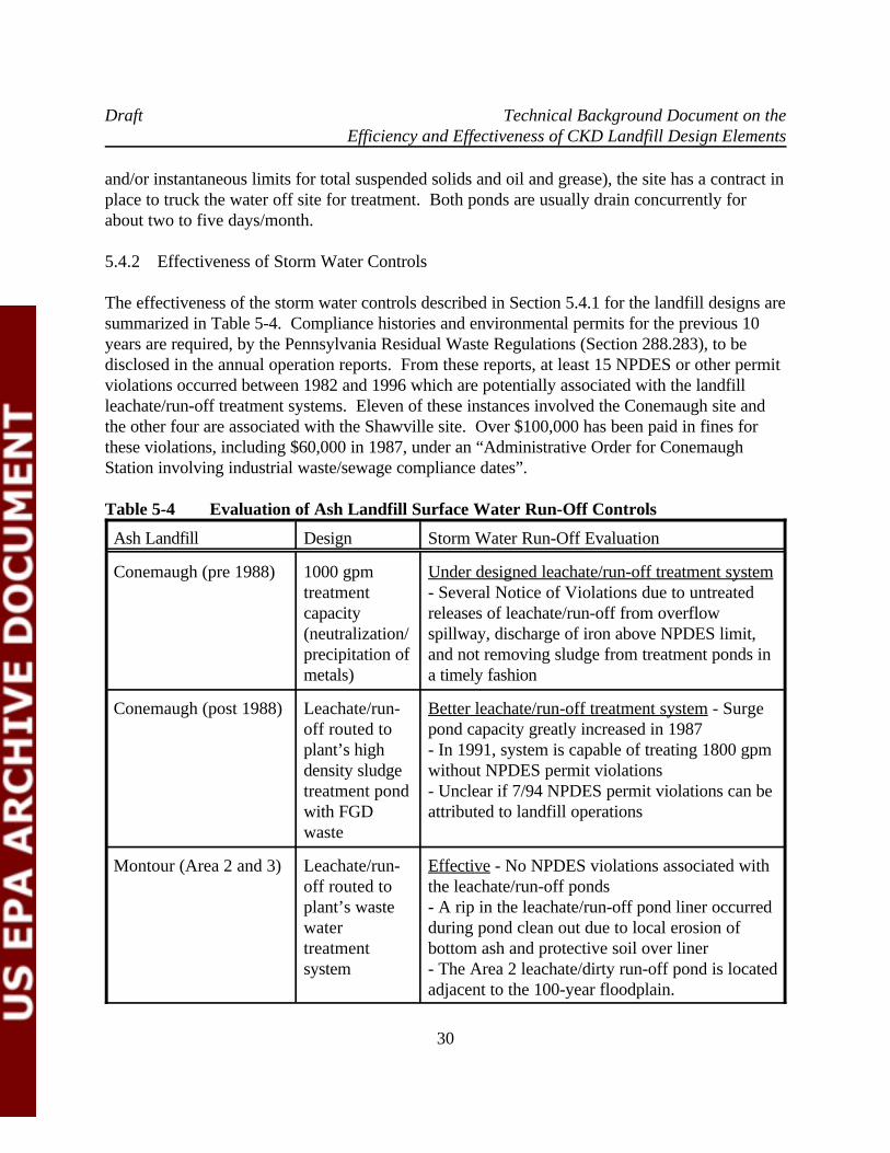
Draft Technical Background Document on theEfficiency and Effectiveness of CKD Landfill Design Elements
30
and/or instantaneous limits for total suspended solids and oil and grease), the site has a contract inplace to truck the water off site for treatment. Both ponds are usually drain concurrently forabout two to five days/month.
5.4.2 Effectiveness of Storm Water Controls
The effectiveness of the storm water controls described in Section 5.4.1 for the landfill designs aresummarized in Table 5-4. Compliance histories and environmental permits for the previous 10years are required, by the Pennsylvania Residual Waste Regulations (Section 288.283), to bedisclosed in the annual operation reports. From these reports, at least 15 NPDES or other permitviolations occurred between 1982 and 1996 which are potentially associated with the landfillleachate/run-off treatment systems. Eleven of these instances involved the Conemaugh site andthe other four are associated with the Shawville site. Over $100,000 has been paid in fines forthese violations, including $60,000 in 1987, under an “Administrative Order for ConemaughStation involving industrial waste/sewage compliance dates”.
Table 5-4 Evaluation of Ash Landfill Surface Water Run-Off Controls
Ash Landfill Design Storm Water Run-Off Evaluation
Conemaugh (pre 1988) 1000 gpm Under designed leachate/run-off treatment systemtreatment - Several Notice of Violations due to untreatedcapacity releases of leachate/run-off from overflow(neutralization/ spillway, discharge of iron above NPDES limit,precipitation of and not removing sludge from treatment ponds inmetals) a timely fashion
Conemaugh (post 1988) Leachate/run- Better leachate/run-off treatment system - Surgeoff routed to pond capacity greatly increased in 1987plant’s high - In 1991, system is capable of treating 1800 gpmdensity sludge without NPDES permit violationstreatment pond - Unclear if 7/94 NPDES permit violations can bewith FGD attributed to landfill operationswaste
Montour (Area 2 and 3) Leachate/run- Effective - No NPDES violations associated withoff routed to the leachate/run-off pondsplant’s waste - A rip in the leachate/run-off pond liner occurredwater during pond clean out due to local erosion oftreatment bottom ash and protective soil over linersystem - The Area 2 leachate/dirty run-off pond is located
adjacent to the 100-year floodplain.
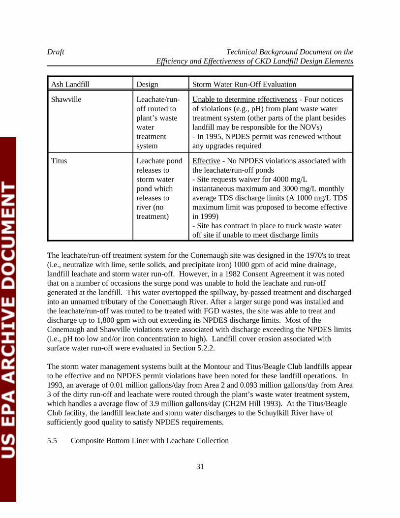
Draft Technical Background Document on theEfficiency and Effectiveness of CKD Landfill Design Elements
Ash Landfill Design Storm Water Run-Off Evaluation
31
Shawville Leachate/run- Unable to determine effectiveness - Four noticesoff routed to of violations (e.g., pH) from plant waste waterplant’s waste treatment system (other parts of the plant besideswater landfill may be responsible for the NOVs)treatment - In 1995, NPDES permit was renewed withoutsystem any upgrades required
Titus Leachate pond Effective - No NPDES violations associated withreleases to the leachate/run-off ponds storm water - Site requests waiver for 4000 mg/Lpond which instantaneous maximum and 3000 mg/L monthlyreleases to average TDS discharge limits (A 1000 mg/L TDSriver (no maximum limit was proposed to become effectivetreatment) in 1999)
- Site has contract in place to truck waste wateroff site if unable to meet discharge limits
The leachate/run-off treatment system for the Conemaugh site was designed in the 1970's to treat(i.e., neutralize with lime, settle solids, and precipitate iron) 1000 gpm of acid mine drainage,landfill leachate and storm water run-off. However, in a 1982 Consent Agreement it was notedthat on a number of occasions the surge pond was unable to hold the leachate and run-offgenerated at the landfill. This water overtopped the spillway, by-passed treatment and dischargedinto an unnamed tributary of the Conemaugh River. After a larger surge pond was installed andthe leachate/run-off was routed to be treated with FGD wastes, the site was able to treat anddischarge up to 1,800 gpm with out exceeding its NPDES discharge limits. Most of theConemaugh and Shawville violations were associated with discharge exceeding the NPDES limits(i.e., pH too low and/or iron concentration to high). Landfill cover erosion associated withsurface water run-off were evaluated in Section 5.2.2.
The storm water management systems built at the Montour and Titus/Beagle Club landfills appearto be effective and no NPDES permit violations have been noted for these landfill operations. In1993, an average of 0.01 million gallons/day from Area 2 and 0.093 million gallons/day from Area3 of the dirty run-off and leachate were routed through the plant’s waste water treatment system,which handles a average flow of 3.9 million gallons/day (CH2M Hill 1993). At the Titus/BeagleClub facility, the landfill leachate and storm water discharges to the Schuylkill River have ofsufficiently good quality to satisfy NPDES requirements.
5.5 Composite Bottom Liner with Leachate Collection
Draft Technical Background Document on theEfficiency and Effectiveness of CKD Landfill Design Elements
32
5.5.1 Use of Composite Liners and Leachate Collection at Fly Ash Landfills
Pennsylvania residual waste regulations require a double bottom liner for industrial Class I wasteswhich exhibit hazardous waste characteristics (e.g., pyrites). Coal is often milled and washed toremove heavy minerals including pyrite prior to being burned in the power plant. When pyrite isoxidized to ferrous iron and sulfate, acid is often generated by the oxidation of ferrous iron andprecipitation of ferric hydroxide. This process is often a source of acid mine drainage and mayresult in pH levels below 2.5 SU. At the Conemaugh and Shawville sites, the pyrites are disposedof in the ash landfill. PDEP has granted a variance for pyrite disposal at the Shawville site,because of the leachate detection system installed below the bottom liner and because of arequirement to install a double liner system for the Phase III/IV expansions after 1997. PDEP istentatively allowing pyrite disposal at the Conemaugh site provided that the facility demonstratesthat the landfill is not leaking or impacting the underlying ground-water system. PDEP has saidthat this could be proved at the Conemaugh site by a ground-water assessment rather than anevaluation of liner integrity (Penelec/GPU 1994). Based on typical analytical results, coal fly ashand bottom ash are commonly classified as Class II and Class III wastes, respectively. Class IIwastes must be disposed in a unit which has a single bottom liner, while Class III wastes have nobottom liner disposal requirement.
The leachate collection and bottom liner designs of the coal ash landfills studied in this TBD aresummarized in Table 5-5. The use of plastic bottom liners, either polyvinyl chloride (PVC) orhigh density polyethylene (HDPE), has been installed throughout the Montour Ash Storage Area3 landfill. For the Conemaugh, Shawville and Titus/Beagle Club landfills, plastic liners wereinstalled in only the newer portions of the landfill. At the Montour Ash Storage Area 2, a plasticliner was used only where the depth to ground water was less than 2 feet below the bottom of thewaste (otherwise, 2-feet of native clay compacted to a permeability less than 10 cm/s was used). -7
No minimum permeability criteria for the soil under the plastic liners was established at any of thestudied sites. The bottom liners were installed over underdrains at the Conemaugh and Montourstorage areas to prevent excessive pore pressure build up below the bottom liner. In the 1992solid waste permit for the Shawville site, a leachate detection system was required under the bottom liner, consisting of a geonet overlying fly ash subbase compacted to at least 95% of themaximum density and with a minimum bearing capacity of 1.5 tons/ft . None of the other sites2
have installed a leachate detection system below the bottom liner. All of the landfills studied haveleachate collection systems installed throughout the landfill. For landfills with plastic liners, theleachate collection systems consist of perforated pipes placed no more than about 200 feet fromeach other in a bottom ash and/or non-calcareous gravel drainage blanket. At all of the landfillsthe plastic liners were placed between two geomembrane layers to protect the liner from excessivestrain and a geofabic was typically installed over the leachate collection system to preventclogging. Quality control procedures used during installation of the plastic liners include non-destructive and destructive seam testing, letters from the liner manufacturer stating the
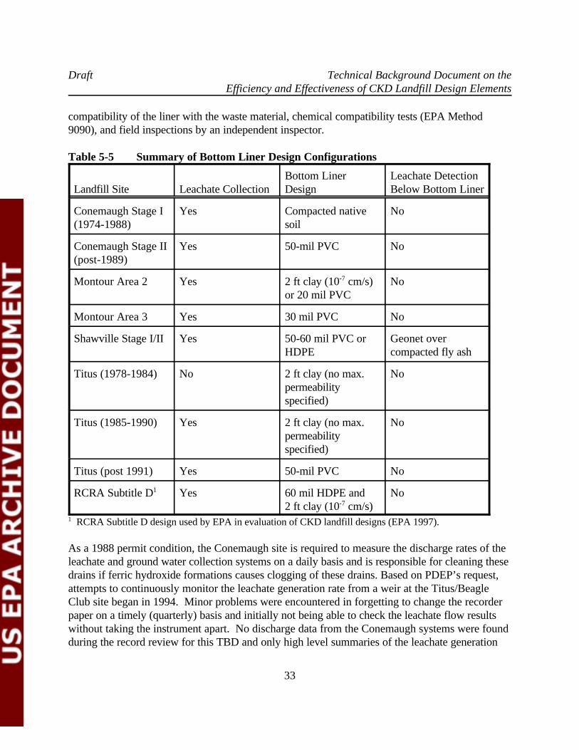
Draft Technical Background Document on theEfficiency and Effectiveness of CKD Landfill Design Elements
33
compatibility of the liner with the waste material, chemical compatibility tests (EPA Method9090), and field inspections by an independent inspector.
Table 5-5 Summary of Bottom Liner Design Configurations
Landfill Site Leachate Collection Design Below Bottom LinerBottom Liner Leachate Detection
Conemaugh Stage I Yes Compacted native No(1974-1988) soil
Conemaugh Stage II Yes 50-mil PVC No(post-1989)
Montour Area 2 Yes 2 ft clay (10 cm/s) No-7
or 20 mil PVC
Montour Area 3 Yes 30 mil PVC No
Shawville Stage I/II Yes 50-60 mil PVC or Geonet overHDPE compacted fly ash
Titus (1978-1984) No 2 ft clay (no max. Nopermeabilityspecified)
Titus (1985-1990) Yes 2 ft clay (no max. Nopermeabilityspecified)
Titus (post 1991) Yes 50-mil PVC No
RCRA Subtitle D Yes 60 mil HDPE and No1
2 ft clay (10 cm/s)-7
RCRA Subtitle D design used by EPA in evaluation of CKD landfill designs (EPA 1997).1
As a 1988 permit condition, the Conemaugh site is required to measure the discharge rates of theleachate and ground water collection systems on a daily basis and is responsible for cleaning thesedrains if ferric hydroxide formations causes clogging of these drains. Based on PDEP’s request,attempts to continuously monitor the leachate generation rate from a weir at the Titus/BeagleClub site began in 1994. Minor problems were encountered in forgetting to change the recorderpaper on a timely (quarterly) basis and initially not being able to check the leachate flow resultswithout taking the instrument apart. No discharge data from the Conemaugh systems were foundduring the record review for this TBD and only high level summaries of the leachate generation
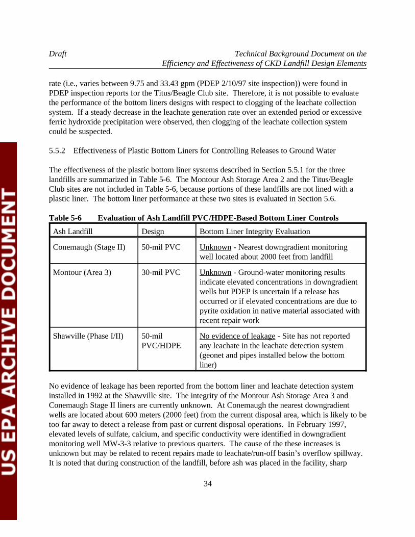
Draft Technical Background Document on theEfficiency and Effectiveness of CKD Landfill Design Elements
34
rate (i.e., varies between 9.75 and 33.43 gpm (PDEP 2/10/97 site inspection)) were found inPDEP inspection reports for the Titus/Beagle Club site. Therefore, it is not possible to evaluatethe performance of the bottom liners designs with respect to clogging of the leachate collectionsystem. If a steady decrease in the leachate generation rate over an extended period or excessiveferric hydroxide precipitation were observed, then clogging of the leachate collection systemcould be suspected.
5.5.2 Effectiveness of Plastic Bottom Liners for Controlling Releases to Ground Water
The effectiveness of the plastic bottom liner systems described in Section 5.5.1 for the threelandfills are summarized in Table 5-6. The Montour Ash Storage Area 2 and the Titus/BeagleClub sites are not included in Table 5-6, because portions of these landfills are not lined with aplastic liner. The bottom liner performance at these two sites is evaluated in Section 5.6.
Table 5-6 Evaluation of Ash Landfill PVC/HDPE-Based Bottom Liner Controls
Ash Landfill Design Bottom Liner Integrity Evaluation
Conemaugh (Stage II) 50-mil PVC Unknown - Nearest downgradient monitoringwell located about 2000 feet from landfill
Montour (Area 3) 30-mil PVC Unknown - Ground-water monitoring resultsindicate elevated concentrations in downgradientwells but PDEP is uncertain if a release hasoccurred or if elevated concentrations are due topyrite oxidation in native material associated withrecent repair work
Shawville (Phase I/II) 50-mil No evidence of leakage - Site has not reportedPVC/HDPE any leachate in the leachate detection system
(geonet and pipes installed below the bottomliner)
No evidence of leakage has been reported from the bottom liner and leachate detection systeminstalled in 1992 at the Shawville site. The integrity of the Montour Ash Storage Area 3 andConemaugh Stage II liners are currently unknown. At Conemaugh the nearest downgradientwells are located about 600 meters (2000 feet) from the current disposal area, which is likely to betoo far away to detect a release from past or current disposal operations. In February 1997,elevated levels of sulfate, calcium, and specific conductivity were identified in downgradientmonitoring well MW-3-3 relative to previous quarters. The cause of the these increases isunknown but may be related to recent repairs made to leachate/run-off basin’s overflow spillway. It is noted that during construction of the landfill, before ash was placed in the facility, sharp
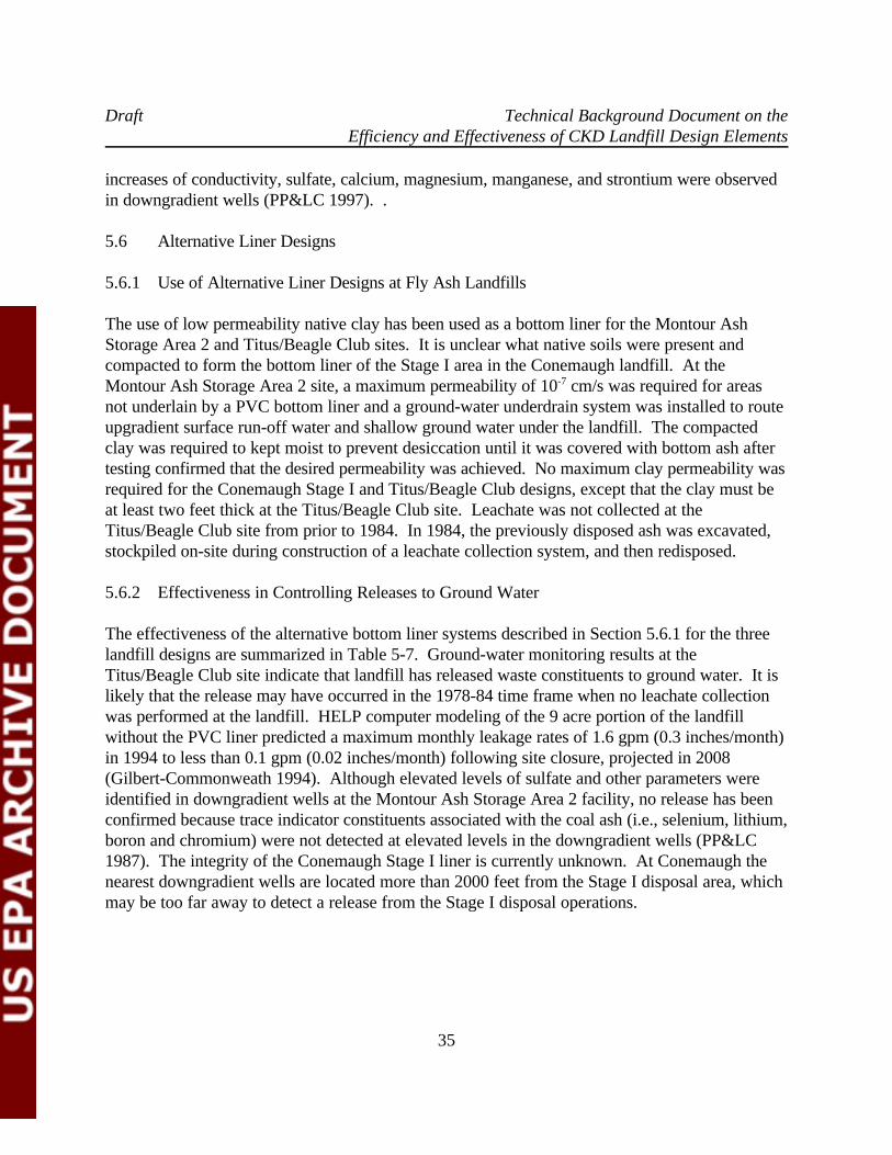
Draft Technical Background Document on theEfficiency and Effectiveness of CKD Landfill Design Elements
35
increases of conductivity, sulfate, calcium, magnesium, manganese, and strontium were observedin downgradient wells (PP&LC 1997). .
5.6 Alternative Liner Designs
5.6.1 Use of Alternative Liner Designs at Fly Ash Landfills
The use of low permeability native clay has been used as a bottom liner for the Montour AshStorage Area 2 and Titus/Beagle Club sites. It is unclear what native soils were present andcompacted to form the bottom liner of the Stage I area in the Conemaugh landfill. At theMontour Ash Storage Area 2 site, a maximum permeability of 10 cm/s was required for areas-7
not underlain by a PVC bottom liner and a ground-water underdrain system was installed to routeupgradient surface run-off water and shallow ground water under the landfill. The compactedclay was required to kept moist to prevent desiccation until it was covered with bottom ash aftertesting confirmed that the desired permeability was achieved. No maximum clay permeability wasrequired for the Conemaugh Stage I and Titus/Beagle Club designs, except that the clay must beat least two feet thick at the Titus/Beagle Club site. Leachate was not collected at theTitus/Beagle Club site from prior to 1984. In 1984, the previously disposed ash was excavated,stockpiled on-site during construction of a leachate collection system, and then redisposed.
5.6.2 Effectiveness in Controlling Releases to Ground Water
The effectiveness of the alternative bottom liner systems described in Section 5.6.1 for the threelandfill designs are summarized in Table 5-7. Ground-water monitoring results at theTitus/Beagle Club site indicate that landfill has released waste constituents to ground water. It islikely that the release may have occurred in the 1978-84 time frame when no leachate collectionwas performed at the landfill. HELP computer modeling of the 9 acre portion of the landfillwithout the PVC liner predicted a maximum monthly leakage rates of 1.6 gpm (0.3 inches/month)in 1994 to less than 0.1 gpm (0.02 inches/month) following site closure, projected in 2008(Gilbert-Commonweath 1994). Although elevated levels of sulfate and other parameters wereidentified in downgradient wells at the Montour Ash Storage Area 2 facility, no release has beenconfirmed because trace indicator constituents associated with the coal ash (i.e., selenium, lithium,boron and chromium) were not detected at elevated levels in the downgradient wells (PP&LC1987). The integrity of the Conemaugh Stage I liner is currently unknown. At Conemaugh thenearest downgradient wells are located more than 2000 feet from the Stage I disposal area, whichmay be too far away to detect a release from the Stage I disposal operations.
Draft Technical Background Document on theEfficiency and Effectiveness of CKD Landfill Design Elements
36
Table 5-7 Evaluation of Ash Landfill Alternative Bottom Liner Controls
Ash Landfill Design Bottom Liner Integrity Evaluation
Conemaugh (Stage I) Compacted Unknown - Overlies former coal strip mine andsoil subbase downgradient monitoring well located over 2000
feet from landfill
Montour (Area 2) 20-mil PVC or No landfill leakage detected - Downgradient2 feet 10 cm/s ground-water monitoring results do not indicate-7
native clay elevated concentrations of trace elementsassociated with coal ash
Titus (1978-91) 2 feet native Known landfill leakage - Downgradient ground-clay soil (no water monitoring results indicate degradation forpermeability sulfate and TDS (first observed in 1988)requirement); - HELP model results predict up to 1.6 gpmno leachate leakage in 1994 (declines to 0.1 gpm leakagecollection in during 5 years following site closure projected in1978-84 2008)
5.7 Landfill Closure and Post-Closure Measures at Fly Ash Landfills
5.7.1 Summary of Closure and Post-Closure Activities at Fly Ash Landfills
Only one of the coal ash landfill study sites has been closed. The Montour Ash Storage Area 2was closed in about 1989 just prior to commencement of fly ash disposal activities in the AshStorage Area 3. The design of this landfill closure includes placing of a one-foot thick native claycover over the landfill, allowing the cover to become densely vegetated, and sampling the ground-water monitoring wells for a 30-year post-closure period. It is noted that a final cover wasinstalled on the side slopes of this landfill during disposal as benches were completely filled withash. As noted in Section 5.2, final vegetated covers are also installed at the other landfills asportions of the final grade is achieved. At the time of Montour Ash Storage Area 2 closure, mostof the landfill sides were covered with the one-foot thick native clay cap and vegetation.
5.7.2 Effectiveness of Closure
The effectiveness of the Montour Ash Storage Area 2 closure design is summarized in Table 5-8. The closure design of the final cap with a one-foot thick native clay soil cover appears to beeffective as evidence by densely vegetated landfill side slopes. However, an adequate soil cover iscurrently not present in one corner at the top of the landfill, resulting is a sparse vegetative cover
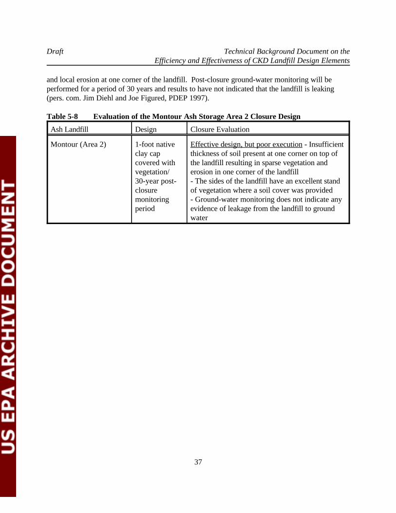
Draft Technical Background Document on theEfficiency and Effectiveness of CKD Landfill Design Elements
37
and local erosion at one corner of the landfill. Post-closure ground-water monitoring will beperformed for a period of 30 years and results to have not indicated that the landfill is leaking(pers. com. Jim Diehl and Joe Figured, PDEP 1997).
Table 5-8 Evaluation of the Montour Ash Storage Area 2 Closure Design
Ash Landfill Design Closure Evaluation
Montour (Area 2) 1-foot native Effective design, but poor execution - Insufficientclay cap thickness of soil present at one corner on top ofcovered with the landfill resulting in sparse vegetation andvegetation/ erosion in one corner of the landfill30-year post- - The sides of the landfill have an excellent standclosure of vegetation where a soil cover was providedmonitoring - Ground-water monitoring does not indicate anyperiod evidence of leakage from the landfill to ground
water

Draft Technical Background Document on theEfficiency and Effectiveness of CKD Landfill Design Elements
38
6.0 CONCLUSIONS
This section summarizes the findings on the effectiveness and efficiency of the landfill designelements evaluated in Section 5 and projects how effective these design elements would functionat CKD landfills. The utility coal ash landfills studied for this TBD were found to use a widevariety of designs to minimize environmental impacts from disposal operations.
6.1 Fugitive Dust Controls
All of the study sites spray unpaved haul roads and disposal areas with water for control offugitive dust emissions. As long as the fly ash and unpaved roads were kept wet, fugitive dustemissions were controlled. Continuous application of water by water trucks was sometimesneeded during extended periods of drought and there is a risk to the environment if a water truckwas broken down during one of these periods.
Additional measures were taken at three power plants to condition the fly ash with water and tocompact it during disposal. This appears to have provided greater control over fugitive dustemissions as well as extending the capacity of these landfills. Due to potential visibility hazardson adjacent Highway 422, 30-foot high wind screens were constructed at the Titus/Beagle ClubAsh Landfill. The wind screens appear to have helped to control fugitive dust emissions, howeverapplication of water over areas prone to dusting is the primary dust control measure at this site. Hoppers or silos were used at all of the utility plants to temporarily store the fly ash as it is beinggenerated and until it is transported to the landfill for disposal. Cleaning and covering of truckswas required at the Conemaugh site when hauling ash from off-site locations.
These dust control measures could be effectively applied at CKD disposal sites. Care must betaken to not over apply water to CKD due to the potential caustic quality of the run-off that maybe generated and because this may result in failure to achieve the desired in-place density duringcompaction. Conditioning CKD with water and compacting it during disposal is expected to helpcontrol fugitive dust emissions. Wind screens and/or spraying of dust suppressants may beconsidered for deployment at CKD disposal sites near populated areas or where there is a highdegree of concern over fugitive dust emissions. Additional fugitive dust control measuresevaluated by EPA for potential use at CKD disposal sites include pelletization of waste CKD and application of a latex or soil cover over the waste pile (ICF 1997).
6.2 Temporary or Interim Landfill Cover
PDEP regulations require installation of vegetated temporary of interim landfill cover if an ashsurface is expected to be exposed for more than six months. The interim cover is required to betemporarily vegetated and otherwise protected against erosion if neither waste nor final cover is
Draft Technical Background Document on theEfficiency and Effectiveness of CKD Landfill Design Elements
39
placed within 30 days (Section 288.234 of the Residual Waste Regulations). At Shawville, abottom ash or soil cover is required when the ash surface is exposed for more than one week. Other sites have procedures to cover unstable fly ash surfaces with soil or bottom ash, on an as-needed basis or if operations are expected to be shut down for extended periods. At most of theutility ash landfills studied in this TBD, it was found that interim or temporary soil covers weregenerally not used. Instead, ash is disposed of in a limited area on a near-continuous basis untilthe final grade is achieved. After the final grade is achieved, a final cover is constructed, and ashdisposal is initiated in a new area. Gully erosion of the final cover has been noted to be an issue atseveral the ash disposal sites, requiring on-going inspection and maintenance.
Disposal operations at coal ash landfills suggest that it may be possible to dispose of CKD without constructing interim covers, if compacted, conditioned CKD is disposed of on a daily basisand an inspection and abatement program is implemented to effectively control fugitive dustemissions and site erosion. Disposal operations should be concentrated in as small area as isfeasible (i.e., an active disposal area of 60 m (200 ft) or less in length). In this way CKD landfillswould be constructed in a phased manner, where disposal cells or benches are filled on asequential basis and capped to minimize infiltration, erosion and fugitive dust emissions prior tofinal closure. A final cover should be installed to stabilize the ash as soon as possible after thefinal grade is achieved.
6.3 Ground-Water Monitoring
A network of upgradient and downgradient monitoring wells/points are being monitored on aquarterly basis at all of the coal ash landfills studied. At the Titus/Beagle Club site, downgradientmonitoring wells, located less than 90 meters (300 feet) from the landfill, have provided timelywarning that the ground-water system has been impacted from ash disposal operations. At theConemaugh site, however, the downgradient wells are located near the projected edge of thelandfill in the year 2028, which is more than 600 meters (2000 ft) from current and past disposaloperations. This ground-water monitoring system is relatively ineffective as an early warningsystem for identifying potential landfill leakage. If the wells were located within 500 feet of thedowngradient edge of the waste management unit, the system would be more effective and wouldbe consistent with EPA’s proposed approach for monitoring ground water at CKD landfills. None of the studied coal ash landfills are located over karst aquifers. For CKD landfills at karsticsites, EPA is proposing are greater degree of site characterization and more sophisticated ground-water monitoring than those used for the studied coal ash landfills.
At the Titus/Beagle Club, Conemaugh and Shawville facilities statistical methods are used toevaluate ground-water monitoring data to determine whether the ash disposal operations haveimpacted ground water. At the Titus/Beagle Club site, the operator/owner used a 99%confidence level and identified several constituents in downgradient wells at concentrations
Draft Technical Background Document on theEfficiency and Effectiveness of CKD Landfill Design Elements
40
exceeding background. However, at the Conemaugh and Shawville sites, the statistical methodsare not consistent with current EPA guidance and would not be as effective in identifyingpotential releases to ground water. It is noted that pre-existing acid mine drainage has impactedthe ground-water system under the Conemaugh and Shawville sites, so that identification ofreleases from these landfills may be difficult to identify. EPA is considering using the statisticaltechniques specified in 40 CFR 258.53(g) and 40 CFR 264.97 to evaluate potential landfillleakage. These regulations appear to include the approach used for the Titus/Beagle Clubground-water assessment.
6.4 Storm Water Controls
At all of the coal ash landfills, surface run-off from unvegetated ash surfaces is collected inleachate and/or storm water run-off collection ponds and treated as necessary for discharge undera NPDES permit. These storm water controls have been designed to accommodate the 25-year,24-hour storm per Section 288.242 of the PA Residual Waste Regulations. Discharges from dirtystorm water collection ponds emergency overflows are permitted at the Conemaugh, MontourAreas 2 and 3, and Titus/Beagle Club landfills for storm events equal to or greater than the 10-year, 24-hour storm. After the vegetation becomes established, the surface water collectionsystem is modified to convey this water downslope of the landfill without collection/treatment. Except for the Montour Area 2 leachate/dirty run-off pond, all of the landfills studied werelocated away from of the 100-year floodplain. Gully erosion of the final cover has been noted tobe an issue at several sites, requiring on-going inspection and maintenance.
At the coal ash landfills studied, at least 15 NPDES permit violations were found potentiallyinvolving landfill leachate/run-off treatment systems. At the Conemaugh and Shawville sites,preexisting acid mine drainage requires greater attention to the design of the treatment systemwhen this waste stream is combined with the leachate and dirty surface water run-off. Routingleachate/storm water run-off waters through the utility plant’s waste water treatment systemappears to provide a greater treatment capacity and to result in a lower potential for exceedingNPDES discharge limits.
Comanagement and cotreatment of landfill leachate and dirty storm water run-off may be aneffective approach at CKD landfills, provided that the waste water treatment system is ofsufficient capacity to handle the quantity of leachate, storm water run-off and potentiallycontaminated ground water for the expected life of the landfill. It may be feasible to treat thiswater in the cement plant’s main waste water treatment system.
6.5 Composite Bottom Liner
Only three of the studied landfills (i.e., Conemaugh Stage II, Shawville Stage I/II, and Montour

Draft Technical Background Document on theEfficiency and Effectiveness of CKD Landfill Design Elements
41
Ash Storage Area 3) were found to have used a modified composite bottom liner design wherethe landfill is entirely underlain by a plastic (e.g., PVC or HPDE) bottom liner. However, therequirements for the clay portion of the composite liner for these landfills was less stringent thanthe 2 feet of clay with a permeability less than 10 cm/s, specified in the RCRA Subtitle D-7
regulations (40 CFR 258.40(a)(2)). At Shawville, the Stage I/II landfill was constructed over theold landfill after the fly ash was compacted to at least 95% of the maximum density and with aminimum bearing capacity of 1.5 tons/ft . No minimum permeability (other than that resulting2
from site clearing, grubbing and rolling soil flat) was required for the subbase material of theConemaugh and Montour landfills. Underdrains were constructed at the Montour andConemaugh landfills to drain upgradient surface water and/or shallow ground water and toprevent excessive pressure heads under the landfill. All these landfills have a leachate collectionsystem installed throughout the landfill immediately overlying the bottom liner.
The Shawville landfill was constructed in 1992 with a leachate detection system (geonet) underthe bottom liner. Because the facility has not reported any fluids from the leachate detectionsystem, the bottom liner at the Shawville landfill appears to be working properly, with nomeasurable leakage. Ground-water monitoring results at the Conemaugh and Montour facilitiesindicate the presence of pre-existing, poor quality ground water under these landfills. This pre-existing, poor quality ground water makes it difficult to evaluate the potential for leakage throughthe landfill bottom liners.
EPA is considering using the RCRA Subtitle D composite liner design as the technical defaultstandard for CKD landfills. EPA’s evaluation of the Subtitle D composite liner design indicatesthat the expected leakage from this design is very small and would be protective of human healthand ground-water resources (EPA 1997). In designing a bottom liner for CKD landfills in non-karstic areas, EPA is considering a performance-based design standard that is based on the RCRASubtitle D performance standard found in 40 CFR 258.40(a)(1). This standard would allow theuse of a modified bottom liner design, such as those found at the coal ash landfill sites, as long asthere is no exceedence of EPA’s maximum contaminant levels (MCLs) for drinking water and/orother health based numbers (HBNs) for arsenic, antimony, barium, beryllium, cadmium,chromium, lead, mercury, nickel, selenium, silver, and thallium in the uppermost aquifer at therelevant point of compliance (POC).
6.6 Alternative Bottom Liner Designs
Portions of the Montour Area 2 and Titus/Beagle Club landfills do not have a plastic bottom liner,but instead use compacted native clay as a bottom liner. At the Montour Area 2 facility, a plasticliner was only used in areas where the depth to water was less than 0.6 meters (2 feet), otherwisethe bottom liner consisted of a 2-foot-thick native clay with a maximum permeability of 10 cm/s. -7
A 2-foot-thick native clay with no permeability requirement was used a bottom liner for the
Draft Technical Background Document on theEfficiency and Effectiveness of CKD Landfill Design Elements
42
Titus/Beagle Club landfill prior to 1991. From 1978 to 1984, the Titus/Beagle Club landfilloperated without a leachate collection system. In 1984-85 this landfill was excavated andstockpiled until redisposed on site in a landfill with a leachate collection system. After 1991, aPVC bottom liner was installed at the Titus/Beagle Club landfill.
Ground-water degradation downgradient of the Montour Area 2 and Titus/Beagle Club facilitieshas been identified from the ground-water monitoring data. Evaluation of trace elementconcentrations in downgradient ground water at the Montour Area 2 facility indicates that noleakage has been confirmed because the degradation appears to be related to oxidation ofnaturally-occurring pyrite in the shale bedrock rather than fly ash constituents. HELP modeling ofthe Titus landfill has predicted a current maximum leakage rate of 1.6 gpm (0.3 inches/month)from the 9 acre portion of the landfill with out a plastic liner. Based on these observations, itappears that alternative bottom liner designs which do not use synthetic liners may be appropriatefor some CKD landfills depending upon site-specific conditions.
EPA’s evaluation of CKD landfill bottom liner designs indicates that CKD landfills located in non-karstic areas with annual rainfall less than about 29 inches may not require plastic liners (i.e.,“modified CKD high” design) and with annual rainfall less than about 10 inches may not requireleachate collection systems (i.e., “modified CKD low” design) (EPA 1997). The leachatecollection system/bottom liner of the “modified CKD high” design consists of a geotextile filterfabric over 1 foot of sand (leachate collection layer), which is underlain by a geotextile supportfabric and 4 feet of compacted CKD with a permeability of 2 x 10 cm/s. The bottom liner of the-5
“modified CKD low” design consists of 4 feet of compacted CKD and does not include a leachatecollection system.
6.7 Landfill Closure and Post-Closure Measures
The Montour Area 2 facility was closed in 1989. Closure activities consisted of completinginstallation of a final 1-foot-thick clay cover over the landfill, allowing it to become vegetated, andcontinuing with the ground-water monitoring program during a 30-year post-closure period. PDEP granted a variance for the 1-foot-thick clay cover based on the results from demonstrationplot test of a 1-foot-thick and 2-foot-thick clay covers performed at the Montour site. A recentinspection of the Montour Area 2 landfill has found that erosion has exposed waste ash in onecorner of the landfill where vegetation did not become sufficiently established. PDEP attribute thepoorer than expected performance of the final cover to unfavorable growing conditions (i.e., soilremoved by erosion, lack of moisture, and excessive wind) at this exposed location. It is notedthat the performance of vegetation growth in a relatively small test plot may not be directlyextrapolated for a large landfill (per. com. Mark Stevens, PDEP 1997).
EPA is considering standards for landfill closure and post-closure requirements based on the
Draft Technical Background Document on theEfficiency and Effectiveness of CKD Landfill Design Elements
43
RCRA Subtitle D regulations (40 CFR 258.60-61). The cover must have a permeability less thanor equal to the bottom liner or natural subsoils or have a permeability no greater than 10 cm/sec,-5
whichever is less. The cover must minimize infiltration by using an infiltration layer that containsat least 18 inches of earthen material. The cover must minimize erosion by using an erosion layerthat contains at least 6 inches of earthen material that is capable of sustaining native plant growth. Similar to the PDEP approach (Section 288.234 of the Residual Waste Regulations), analternative landfill final cover design may be approved as long as it provides an equivalent degreeof infiltration and erosion protection.
Draft Technical Background Document on theEfficiency and Effectiveness of CKD Landfill Design Elements
44
7.0 REFERENCES
Adriano, D.C., A.L. Page, A.A. Elseewi, A.C. Chang, and I. Straughan, 1980. “Utilization andDisposal of Fly Ash and Other Coal Residues in Terrestrial Ecosystems - A Review”,Journal of Environmental Quality. Vol. 9, no. 3. pg.333.
CH2M Hill, 1993. “Wastewater Management Plan For Montour Steam Electric Station”. Prepared for Pennsylvania Power and Light Company.
(CEC) Civil & Environmental Consultants, Inc., 1992. “Preliminary Groundwater Assessment,Metropolitan Edison, Titus Generating Station and Beagle Club Ash-Disposal Site”,Prepared for Metropolitan Edison Company, Reading, Pennsylvania. CEC Project 92154. December 28, 1992.
Dames & Moore, 1996. “Final Closure Plan for the Closure of the Cement Kiln Dust Pile,Metaline Falls, Washington.” Revised April 11, 1996.
(EPA) U.S. Environmental Protection Agency, 1988. Report to Congress: Wastes from theCombustion of Coal by Utility Power Plants. Office of Solid Waste and EmergencyResponse. February 1988. EPA/530-SW-88-002.
(EPA) U.S. Environmental Protection Agency, 1992. Statistical Analysis of Ground-WaterMonitoring Data at RCRA Facilities, Draft Addendum to Interim Final Guidance. Officeof Solid Waste, Permits and State Programs Division. July 1992.
(EPA) U.S. Environmental Protection Agency, 1993a. Report to Congress on Cement Kiln Dust,Volume II: Methods and Findings. Office of Solid Waste. December 1993.
(EPA) U.S. Environmental Protection Agency, 1993b. Supplemental Analysis on Potential Risksto Human Health and the Environment from Large-Volume Coal Combustion Waste. July30, 1993.
(EPA) U.S. Environmental Protection Agency, 1995. Regulatory Determination on Cement KilnDust; Final Rule. Federal Register, Vol. 60, No. 25, Page 7366-7376. February 7, 1995.
(EPA) U.S. Environmental Protection Agency, 1997. “Draft Technical Background Document: Development of Performance Standards and Design and Operating Criteria for CKDLandfills”. (Chapters 2 and 3 only). Office of Solid Waste. June 1997.
Draft Technical Background Document on theEfficiency and Effectiveness of CKD Landfill Design Elements
45
(GAI) GAI Consultants, Inc., 1995. “Ground-Water Assessment Report, Shawville Ash DisposalSite, Clearfield County, Pennsylvania”. Prepared for the Pennsylvania Electric Company. Project 92-220-74, Task 02. October 1995.
(GAI) GAI Consultants, Inc., 1996. “Ground-Water Assessment Report, Conemaugh GeneratingStation Disposal Site, Indiana County, Pennsylvania”. Prepared for the PennsylvaniaElectric Company. Project 92-220-71, Task 02. January 10, 1996.
Gilbert/Commonwealth, Inc., 1989. “Metropolitan Edison Company, Titus Generating Station,Beagle Club Ash Disposal Site Expansion, Phase I and Phase II Application”. Preparedfor the Metropolitan Edison Company, Reading Pennsylvania. August 1989 - Revision 1.
Gilbert/Commonwealth, Inc., 1994. “Preliminary Application for Permit Modification forResidual Waste Disposal Facility Permitted Before July 4, 1992, Titus Generating Station,Beagle Club Ash Disposal Site”. Prepared for the Metropolitan Edison Company,Reading Pennsylvania. June 27, 1994.
(ICF) ICF Resources Incorporated, 1993. Coal Combustion Waste Management Study. Preparedfor U.S. Department of Energy Office of Fossil Energy (Contract DE-AC01-91FE62017,Task 8). February, 1993.
(ICF) ICF Consulting Group, 1997. Revised Results of Emission Reduction Analysis. Memorandum from LuAnn Gardner, Cynthia Steiner, Liz Nixon and Larry Huffman, ICFto Bill Schoenborn, EPA. (Task 10, Work Assignment 215, Contract No. 68-W4-0030). February, 14 1997.
L.R. Kimball and Associates, Inc., 1992. “Shawville Generating Station, Proposed Ash DisposalSite, Phase II Solid Waste Disposal Application”. Prepared for the Pennsylvania ElectricCompany. February 1992 (Revised).
Montour County Planning Commission and Derry Township Board of Supervisors versus PaDERand PP&LC, 1986. “Settlement Agreement”. Docket Nos. 84-249-M and 84-255-M.May 1996.
(PaDER) Pennsylvania Department of Environmental Resources, 1989. Internal memo from SaraPantelidou to Bruce Beitler, entitled “Ground Water Monitoring Results for Met-Ed(AKA Titus Station, AKA Beagle Club Ash Disposal)”. February 14, 1989.
Draft Technical Background Document on theEfficiency and Effectiveness of CKD Landfill Design Elements
46
(PDEP) Pennsylvania Department of Environmental Protection, 1996. Letter from Jeffery Smith,Hydrogeologist, PDEP to John Reilly, Environmental Manager, GPU Generation Inc.,entitled “Conemaugh Generating Station, Groundwater Assessment Report, Ash/MineRefuse Disposal Landfill”. October 24, 1996.
(PDEP) Pennsylvania Department of Environmental Protection and GPU-Genco, 1996. “MeetingLog for Titus Station Ash Site Repermitting”. March 27, 1996.
(Penelec/GPU) Pennsylvania Electric Company/General Public Utilities, 1994. “PaDER, Penelec,GAI Meeting Minutes, Residual Waste Evaluation of Liner Integrity (ELI) Plan Meeting,Discussion of PaDER’s Comments”. Meeting held at PaDER Office, Pittsburgh,Pennsylvania, on January 12, 1994. Draft meeting minutes transmitted to PennsylvaniaDepartment of Environmental Resources on March 30, 1994 as an enclosure to a letterentitled “Evaluation of Liner Integrity, Conemaugh and Keystone Ash/Mine RefuseDisposal Sites”.
(Penelec and PaDER) Pennsylvania Electric Company and Pennsylvania Department ofEnvironmental Resources, 1982. “Consent Order and Agreement.” ConemaughGenerating Station and Seward Generating Station, Solid Waste Management Act, CleanStreams Law. November 19, 1982.
(Penelec and PaDER) Pennsylvania Electric Company and Pennsylvania Department ofEnvironmental Resources, 1984. “Amendment to Consent Order and Agreement.” Conemaugh Generating Station and Seward Generating Station, Solid Waste ManagementAct, Clean Streams Law. October 17, 1984.
Personal Communication with Jim Diehl and Joe Figured, Bureau of Land Recycling & WasteManagement, Pennsylvania Department of Environmental Protection, NorthcentralRegion, June 24 and 27, 1997.
Personal Communication with John Hamilton, Facilities Manger, Bureau of Land Recycling &Waste Management, Pennsylvania Department of Environmental Protection, NorthcentralRegion. March 19 and June 11, 1997.
Personal Communication with Mike Maiole, Pennsylvania Department of EnvironmentalProtection, Reading, PA. June 19, 1997.
Personal Communication with Mick Planinsek, Pennsylvania Department of EnvironmentalProtection, Greensburg, PA. June 17, 1997.
47
Personal Communication with Mark Stevens and Jason Fellon, Bureau of Land Recycling &Waste Management, Pennsylvania Department of Environmental Protection, NorthcentralRegion, June 30, 1997.
(PP&LC) Pennsylvania Power & Light Company, 1981. “Montour SES, Ash Disposal Area No.2, Phase I Design Concept and Operating Plan”. June 10, 1981.
(PP&LC) Pennsylvania Power & Light Company, 1987. “Montour Ash Storage Area No. 2,Ground Water Assessment, Data Review”. November 1987.
(PP&LC) Pennsylvania Power & Light Company, 1997. Letter report from Jerome Texler,Compliance Services Manager to Jim Diehl, PDEP entitled “Montour Steam ElectricStation, Ash Area No. 3, Quarterly Ground Water Report”. File 773187-05C. February27, 1997.
(SAIC) Science Applications International Corporation, 1997. “Draft Technical BackgroundDocument on the Efficiency and Effectiveness of CKD Landfill Design Elements,Identification of Candidate Landfills for Further Study”. Prepared for EPA, Office ofSolid Waste. EPA Contract 68-W4-0030, Work Assignment 215, Task 16. March 28,1997.
Sterner, Ray, 1994. “The Climate of Pennsylvania”. John Hopkins University Applied PhysicsLaboratory.
APPENDIX A - FIGURES
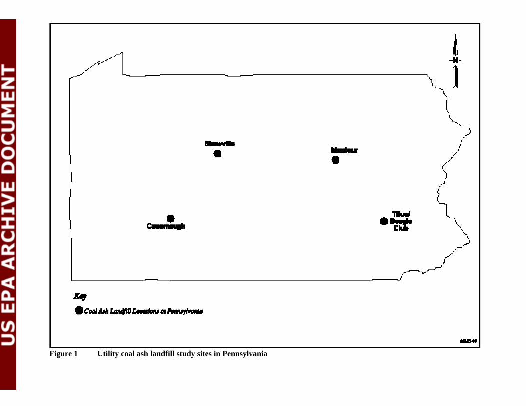
Figure 1 Utility coal ash landfill study sites in Pennsylvania
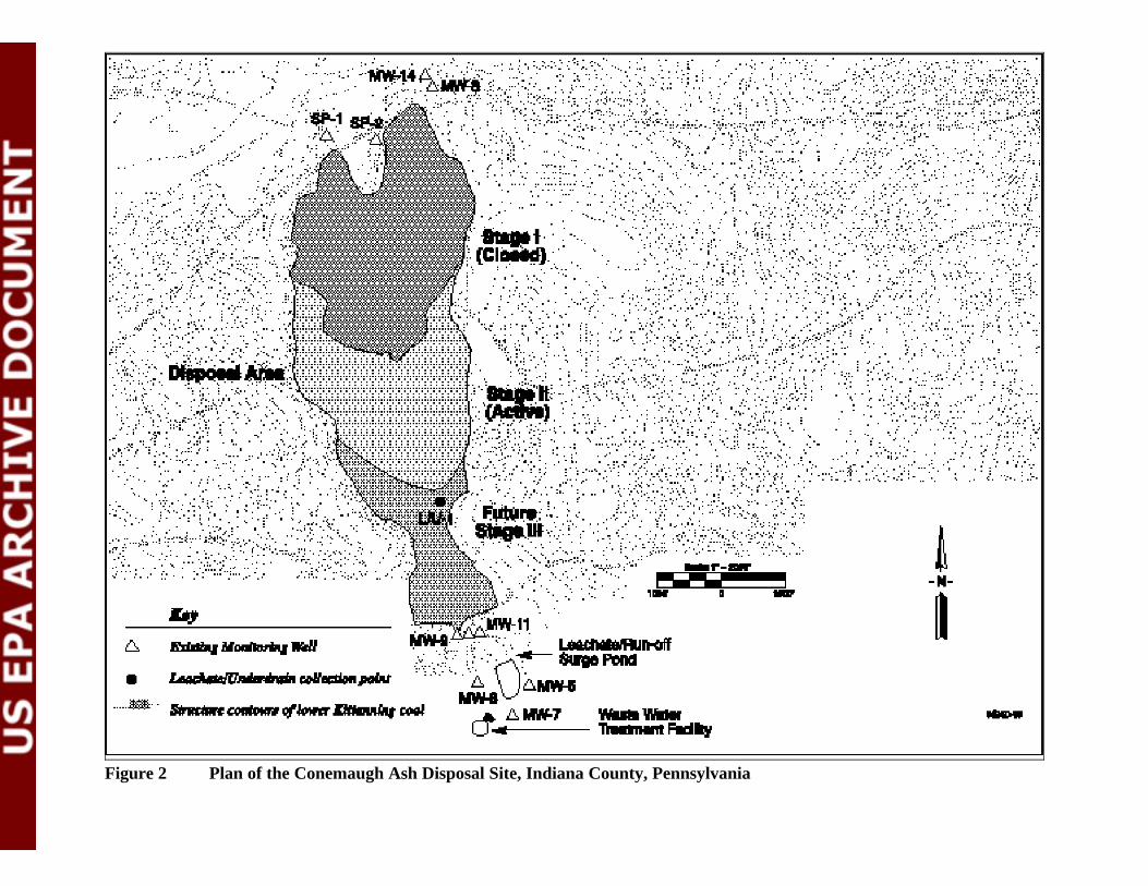
Figure 2 Plan of the Conemaugh Ash Disposal Site, Indiana County, Pennsylvania
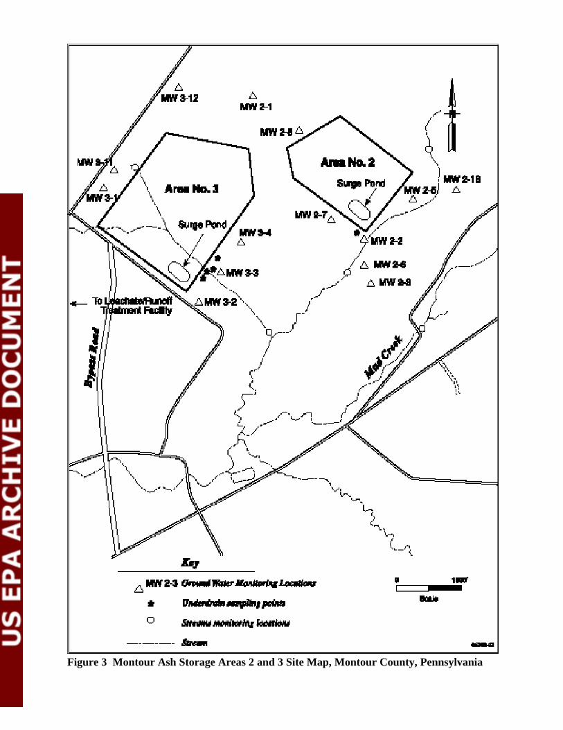
Figure 3 Montour Ash Storage Areas 2 and 3 Site Map, Montour County, Pennsylvania
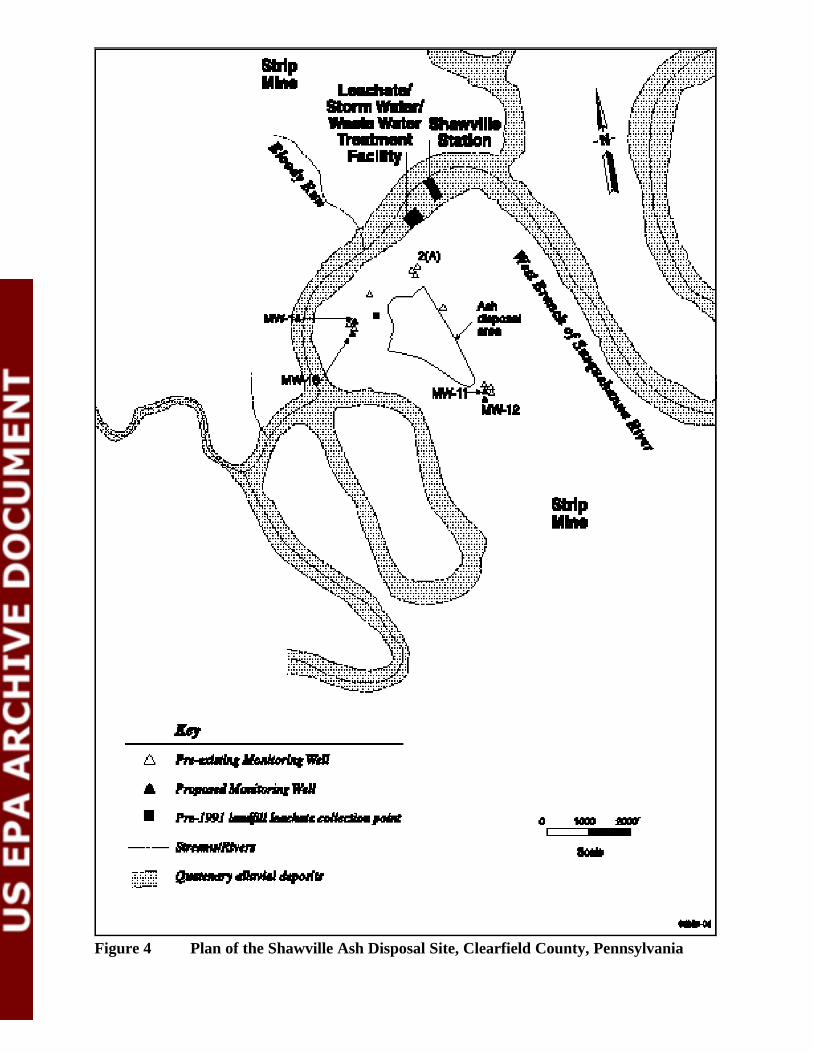
Figure 4 Plan of the Shawville Ash Disposal Site, Clearfield County, Pennsylvania
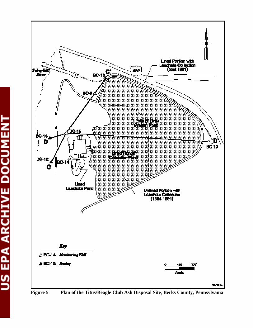
Figure 5 Plan of the Titus/Beagle Club Ash Disposal Site, Berks County, Pennsylvania

APPENDIX B - TELEPHONE CONVERSATION SUMMARIES
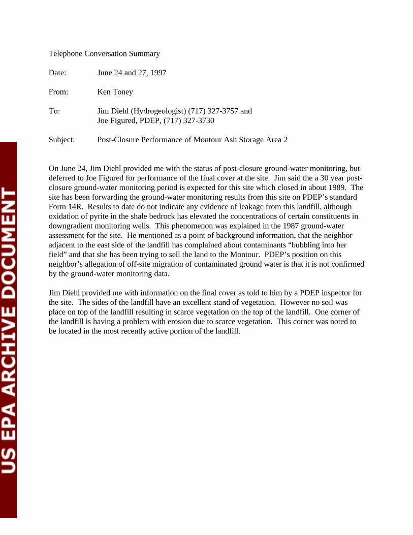
Telephone Conversation Summary
Date: June 24 and 27, 1997
From: Ken Toney
To: Jim Diehl (Hydrogeologist) (717) 327-3757 and Joe Figured, PDEP, (717) 327-3730
Subject: Post-Closure Performance of Montour Ash Storage Area 2
On June 24, Jim Diehl provided me with the status of post-closure ground-water monitoring, butdeferred to Joe Figured for performance of the final cover at the site. Jim said the a 30 year post-closure ground-water monitoring period is expected for this site which closed in about 1989. Thesite has been forwarding the ground-water monitoring results from this site on PDEP’s standardForm 14R. Results to date do not indicate any evidence of leakage from this landfill, althoughoxidation of pyrite in the shale bedrock has elevated the concentrations of certain constituents indowngradient monitoring wells. This phenomenon was explained in the 1987 ground-waterassessment for the site. He mentioned as a point of background information, that the neighboradjacent to the east side of the landfill has complained about contaminants “bubbling into herfield” and that she has been trying to sell the land to the Montour. PDEP’s position on thisneighbor’s allegation of off-site migration of contaminated ground water is that it is not confirmedby the ground-water monitoring data.
Jim Diehl provided me with information on the final cover as told to him by a PDEP inspector forthe site. The sides of the landfill have an excellent stand of vegetation. However no soil wasplace on top of the landfill resulting in scarce vegetation on the top of the landfill. One corner ofthe landfill is having a problem with erosion due to scarce vegetation. This corner was noted tobe located in the most recently active portion of the landfill.
Telephone Conversation Summary
Date: March 19, 1997 (same date as telephone conversation)
From: Ken Toney, SAIC
To: John Hamilton, Facilities Manager, Northcentral Region, Bureau of LandRecycling & Waste Management, Pennsylvania Dept. Of Environmental Protection(717) 327-3653
Subject: Utility Ash Landfills in the Pennsylvania Northcentral Region
I identified twelve utility fly ash landfills Work Assignment 219 listed in Pennsylvania. He wasfamiliar with the Shawville and two Montour facilities. Engineering reports on these facilities areavailable in his office. He provided me with the following information.
Montour Ash Disposal Area 2. Disposal Area 2 was permitted in the early 1980s (1981?) andclosed in 1989. The oldest half has a bottom clay liner and the newer half has a PVC liner.
Montour Ash Disposal Area 3. Disposal Area 3 is not currently used because all of the new ash isable to be marketed. It is considered to be filled to about half of its design capacity. At thepower plant, dry fly ash is stored in a silo, it is then conditioned with water and loaded into atruck for delivery to the disposal site. Disposal Area 3 has a HDPE bottom liner.
Montour Ash Disposal Areas 2 and 3. Both landfills generate leachate which is treated at an on-site water treatment facility which discharges water under a NPDES permit. The landfills havebeen designed to accommodate run-on/run-off associated with a 25 year storm. The site does nothave a storm water permit, but surface water run off from the landfill is collected and tested; if“dirty” it is routed to the treatment plant, if “clean”it is discharged without treatment. PDEP isattempting to get a bond from Montour to ensure that the landfills will eventually be cappedproperly. Montour was one of the first residual waste sites to have lined landfills in theNorthcentral Region. EPRI has conducted a number of studies at the site particularly on thepotential for the ash to generate leachate. A study cell was constructed and lysimeters wereinstalled to collect vadose water samples. The combined area of disposal areas 2 and 3 is 30acres.
Shawville. In 1996, the site was sold to GPU (no longer PA Electric). The landfill coversapproximately 40.5 acres. It began operation in the 1950s and was permitted in January 1991. Anew area of the landfill has an HDPE single liner, but the old area is unlined. There is no dailycover requirement, but an intermediate cover is required for ash that is exposed for more thanabout one week. The landfill has been designed for the 25-year storm. Storm water and landfillleachate is routed to a treatment lagoon and ultimately discharged under a NPDES permit. Afinal cap has not been design, but PDEP is attempting to get a bond from Shawville to ensure thatthe landfill will eventually be capped properly. PDEP is asking Shawville to commit to a cap inthe future even though a final cap is not currently required.
Telephone Conversation Summary
Date: June 11, 1997
To: John Hamilton, Facilities Manager, Northcentral Region, Bureau of Land Recycling & Waste Management, Pennsylvania Department of Environmental Protection (717) 327-3653
From: Ken Toney, SAIC
Subject: Montour and Shawville Coal Ash Landfills
Following a records review of these two sites, I asked John for clarification on the followingquestions:
Montour
What are the results from the airborne particulate monitoring that was done as part of the 1986Consent Agreement for Site 2 in 1986? The Consent Agreement was between the Township andMontour, these monitoring results were not forwarded to PDEP. From his experience withregulating the site, Montour’s fugitive dust control practices are “working fine”. The sitecompacts moist ash, is in a fairly remote location, and there are no outstanding air complaintsrelated with the landfill.
What are the Module 8 parameters in the 1987 Site 3 permit? These parameters consist of 14organic compounds and 12 toxic metals.
Why is a two foot final cover required for Site 3 but only a one foot cover for Site 2? Does thisrequirement have anything to do with the vegetation tests plots that were done at Site 2? A 2foot final cover is a requirement of Pennsylvania regulations. Montour could request a permitmodification if they show that a thinner cover would provide an equivalent degree of protection. The previous vegetation test plots results were not considered, because Montour has notrequested a permit modification.
What is the current evaluation of releases from Site 3 to the ground water system? PDEP iscurrently reviewing the permit renewal application for Site 3. They are uncertain if releases fromthe landfill are affecting downgradient ground water quality or if it is as Montour claims due tooxidation of pyrite in native soil and bedrock.
Shawville
What are the results of leachate detection monitoring of the landfill to date? The site has notreported any leachate in the leachate detection monitoring system.

How are the fugitive dust control practices working? There are no fugitive dust control issueswith Shawville because it is in a location even more remote from populations than is Montour andthey compact the moist ash as it is disposed of.
Any problems with the 1995 ground water assessment? The site is affected by previous stripmining activity, therefore comparing downgradient to upgradient ground water monitoring resultsis not appropriate. The ground water assessment was sufficient given the conditions at thelandfill.
Telephone Conversation Summary
Date: June 19, 1997
To: Mike Maiole, PDEP - Reading, PA; (610) 916-0100
From: Ken Toney, SAIC
Subject: Titus/Beagle Club Ash Landfill
Mike gave me the following information on the Beagle Club Ash Landfill:
C The wind screens are about 30 feet high and consist of telephone poles with fabricstretched between them.
C His opinion was that the wind screens helped to control dusting but keeping the ash moistwas required to effectively control fugitive dust emissions. Overall the site’s dust controlprogram has been effective.
C He stated that the site is still performing quarterly ground-water monitoring of the sameparameters in their 1991 permit. No ground water clean up has been required yet. However, PDEP has not formally accepted the site’s proposal to have less stringentmandatory abatement levels for sulfate and TDS.
Telephone Conversation Summary
Date: June 17, 1997
To: Mick Planinsek, PDEP-Greensburg, (412) 725-5431
From: Ken Toney, SAIC
Subject: Fugitive Dust Controls at Conemaugh Ash Disposal Site
Mick is responsible for performing routine Pennsylvania Department of Environmental Protection(PDEP) inspections at the Conemaugh Ash Disposal Site. I reviewed with him that Conemaugh isrequired to implement fugitive dust controls (spraying with water or other measures) on an asneeded basis and that the waste disposal permit leaves the choice of dust control methods up tothe site as long as it works. He said for the most part Conemaugh’s fugitive dust control programwas working well. However, they may have problems controlling dust in August, when it getshot for several days in a row. In these situations, the water trucks must continuously make therounds watering the roads and the disposal area. He agreed with my conclusion thatimplementing effective dust controls requires ongoing monitoring and maintenance
He mentioned that PennElec (one of the owners at Conemaugh) is required to implement fugitivedust controls on an as needed basis at their Homer City and Keystone plants, which are in thesame general region as Conemaugh. Homer City has been issued a NOV for fugitive dustcontrols. Contributing factors to fugitive dust at Homer City include being in a more exposedlocation (Conemaugh is nestled in a valley) and has poorer quality ash (Conemaugh’s ash is lesssusceptible to dusting because either coarser grained and/or is mixed FGD waste). At HomerCity, an approved dust suppressant (Syntex - a product of Penzoil) was applied to the site in Mayand appeared to be working a month later. He remarked that the Syntex appeared to go on like acoat of paint when it was applied, in terms of thickness and consistency. Syntex was only appliedto inactive areas and is not expected to work if disturbed by vehicles.
Mick mentioned that Conemaugh was currently transporting most of their ash to the coal cleaningplant which is supporting PennElec’s three plants, in order to stabilize coal refuse sludge resultingfrom coal milling and washing.
Telephone Conversation Summary
Date: June 30, 1997
From: Ken Toney
To: Mark Stevens (geologist) (717) 327-3653 and Jason Fellon (soil scientist), PDEP, (717) 327-3730
Subject: Post-Closure Performance of Montour Ash Storage Area 2
Mark Stevens returned my call regarding closure of the Montour Ash Storage Area 2. He iscurrently reviewing a permit application for continued operation at Montour. He provided someadditional information to that provided by Joe Figured and Jim Deal last week. He said that thelandfill is in a exposed position with low-lying surrounding countryside. The cover of the landfillis exposed to wind and surface run-off erosion and has a hard time holding moisture. These arenot ideal conditions for growing vegetation. I mentioned that the permit required a test plot usinga one foot soil cover and that the results appeared to be acceptable even though it took a littlelonger than the two-foot soil plot to become established. He said that what is seen in a small scaletest may not always be extrapolated to an entire landfill. He transferred me to Jason Fellon whocould explain more about PDEP’s landfill cover requirements.
Jason said that PA residual regulations require a 2-foot final soil cover, unless an equivalent coverthat meets the performance standards is provided. He faxed me the PA regulations for final coverrequirements. Some important points for landfill covers include removal of large rocks greaterthan 6 inches, having a high percentage of fines (to hold water), and ensuring that the soil has aproper balance of nutrients (fertility testing). He mentioned that fertility testing is often overlooked in the design of landfill covers (not considered in computer models). He mentioned thatthere is a balance in the amount of organic matter that is needed in the landfill cover. Too muchorganic matter could make the cover combustible.