Technical Assignment 2 - Penn State Engineering · Technical Assignment 2. ... There is enough...
27
Matthew Trethaway Lighting/ Electrical AE 481W 10/26/2011 Advisor: Ted Dannerth Corbin Building Technical Assignment 2
Transcript of Technical Assignment 2 - Penn State Engineering · Technical Assignment 2. ... There is enough...
Matthew Trethaway Lighting/ Electrical
AE 481W 10/26/2011
Advisor: Ted Dannerth
Corbin Building
Technical Assignment 2

10/26/2011 Technical Report II 1
Matthew Trethaway | Lighting/Electrical | Corbin Building | 192 Broadway, New York | Advisor: Ted Dannerth
Executive Summary
The following report is an overview and analysis of the existing electrical system for the Corbin
Building in New York City, NY. The 53,000 square foot building is a multi-use facility composed of street
level retail and eight floors of open office space. The building is to accommodate a variety of store and
office configurations therefore the electrical system needs to be flexible to control the building systems.
The documentation and analysis includes an overall summary of the electrical system including
power distribution, utility information, service entrance, voltage system, emergency system and major
equipment and loads. The service entrance size was calculated three ways to show the size of the
system for each design phase. Communication systems summary was provide for each system in the
building.. A single-line diagram is included to show the electrical distribution system thought the
building starting at the service entrance and ending at the branch circuit panels.
10/26/2011 Technical Report II 2
Matthew Trethaway | Lighting/Electrical | Corbin Building | 192 Broadway, New York | Advisor: Ted Dannerth
Table of Contents
Executive Summary .......................................................................................... 1
Section 1: Power Distribution Systems ............................................................. 3
Summary .......................................................................................................................................... 3
Utility Company Information ........................................................................................................... 3
Service Entrance .............................................................................................................................. 3
Voltage Systems ............................................................................................................................... 4
Emergency Power System ................................................................................................................ 4
Locations of Switchgear ................................................................................................................... 4
Over-Current Devices ....................................................................................................................... 5
Transformers .................................................................................................................................... 5
Special Equipment ........................................................................................................................... 5
Lighting Loads .................................................................................................................................. 6
Lighting Controls .............................................................................................................................. 6
Mechanical and Other Loads ........................................................................................................... 6
Service Entrance Size ....................................................................................................................... 8
Environmental Stewardship Design ............................................................................................... 10
Design Issues .................................................................................................................................. 10
Single-Line Diagram ....................................................................................................................... 10
Section 2: Communication Systems ................................................................................ 10
Telecommunication System ........................................................................................................... 11
Security System .............................................................................................................................. 11
Fire Alarm System .......................................................................................................................... 11
Appendix A: Single Line ...................................................................................................... 12
Appendix B: Fluorescent Lamps/ Ballast Combinations ........................................... 15
10/26/2011 Technical Report II 3
Matthew Trethaway | Lighting/Electrical | Corbin Building | 192 Broadway, New York | Advisor: Ted Dannerth
Section 1: Power Distribution Systems
Summary The electrical distribution system in the Corbin Building is provided by Con Edison. The service
entrance comes from the fifth floor of the Fulton Street Transit Center (FSTC), which is the neighboring
building on the north-side. The service entrances enters the Corbin Building on the fifth floor and goes
down to the basement to feed a 1200A switchboard with a AIC rating of 100K which than services other
branch circuits of the electrical system.
There are two voltages in the building, the primary voltage is 265/460V, 3PH, 4W and the
secondary voltage is 120/208V, 3PH, 4W. The mechanical, escalator and elevator systems run on 460V.
The lighting and plug loads run on 120V. The emergency backup system consists of a UPS to operate the
emergency lights.
Utility Company Information The utility company for the Corbin building is Con Edison. They are located at Cooper Station
P.O. Box 138, New York, NY 10276-0138 and can be contacted at 1-800-75-CONED. There website is http://www.coned.com/.
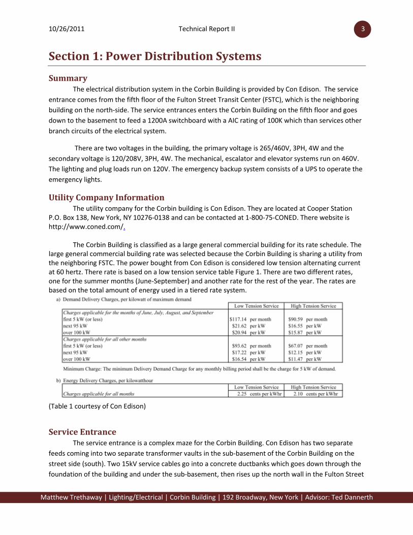
The Corbin Building is classified as a large general commercial building for its rate schedule. The large general commercial building rate was selected because the Corbin Building is sharing a utility from the neighboring FSTC. The power bought from Con Edison is considered low tension alternating current at 60 hertz. There rate is based on a low tension service table Figure 1. There are two different rates, one for the summer months (June-September) and another rate for the rest of the year. The rates are based on the total amount of energy used in a tiered rate system.
(Table 1 courtesy of Con Edison)
Service Entrance The service entrance is a complex maze for the Corbin Building. Con Edison has two separate
feeds coming into two separate transformer vaults in the sub-basement of the Corbin Building on the
street side (south). Two 15kV service cables go into a concrete ductbanks which goes down through the
foundation of the building and under the sub-basement, then rises up the north wall in the Fulton Street

10/26/2011 Technical Report II 4
Matthew Trethaway | Lighting/Electrical | Corbin Building | 192 Broadway, New York | Advisor: Ted Dannerth
Transit Center to the sixth floor. The service then feeds the four transformers owned by the MTA.
Transformers are feed with three-phase 460V four-wire plus ground 4000A bustduct down to the fifth
floor of FSTC to a CT cabinet. The busduct feeding the CT cabinet is metered to monitor usage. A 2000A
fused CT cabinet a feeds the Corbin Building. The feeder is routed through the fire-rated wall between
FSTC and Corbin Building and goes down a shaft in the electrical closet (C503) on the fifth floor to the
basement level electrical room (CP03) to a 1200A switchboard which contains a meter to monitor usage.
Voltage Systems The Corbin Building has two utilization voltages within the building. The primary voltage is
265/460V, 3PH, 4W. The secondary voltage is 120/208V, 3PH, 4W. 460V, 3PH is distributed to the
escalator equipment, elevators, and also the mechanical equipment. Some of the unit heaters and small
mechanical pumps operate at 208V, 1PH or 208V, 3PH, while lighting and receptacle loads operate at
120V, 1PH.
Emergency Power System The emergency system is feed from the FSTC backup generators to a UPS located in the
electrical room in the basement of the Corbin Building. The 30kVA UPS input is 460V, 3PH, 3W plus
ground and outputs 208V, 3PH, 4W +G. There is enough storage in the batteries to operate 24kW for 15
minutes. All the emergency lighting and exit signs are connected to the UPS so they do not flicker when
power is lost.
Locations of Switchgear The location of the switchboard is in the basement level electrical room of the Corbin Building.
There are two distribution boards in the electrical room; one serves the panelboards on the sub-
basement to the fourth floor and the other board serves panels on floors five to eight. Also, both the
transformers are located within the electrical room. The escalator control room in the sub-basement
contains a distribution board for all the escalator equipment. In the elevator machine room on the ninth
floor there is an elevator distribution board. Each floor contains an electrical closet which the utility
shaft rising through it.
10/26/2011 Technical Report II 5
Matthew Trethaway | Lighting/Electrical | Corbin Building | 192 Broadway, New York | Advisor: Ted Dannerth
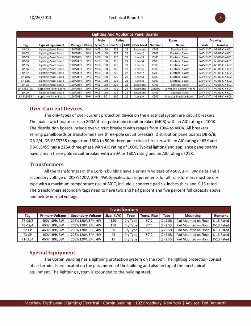
Over-Current Devices The only types of over-current protection device on the electrical system are circuit breakers.
The main switchboard uses an 800A three-pole main circuit breaker (MCB) with an AIC rating of 100K.
The distribution boards include over-circuit breakers with ranges from 100A to 400A. All breakers
serving panelboards or transformers are three-pole circuit breakers. Distribution panelboards DB-5/8,
DB-S/4, DB-ESC5758 range from 150A to 500A three-pole circuit breaker with an AIC rating of 65K and
DB-EL5455 has a 225A three-phase with AIC rating of 100K. Typical lighting and appliance panelboards
have a main three-pole circuit breaker with a 50A or 150A rating and an AIC rating of 22K.
Transformers All the transformers in the Corbin building have a primary voltage of 460V, 3PH, 3W delta and a
secondary voltage of 208Y/120V, 3PH, 4W. Specification requirements for all transformers must be dry-
type with a maximum temperature rise of 80°C, include a concrete pad six-inches thick and K-13 rated.
The transformers secondary taps need to have two and half percent and five percent full capacity above
and below normal voltage.
Special Equipment The Corbin Building has a lightning protection system on the roof. The lighting protection consist
of air terminals are located on the parameters of the building and also on top of the mechanical
equipment. The lightning system is grounded to the building steel.

10/26/2011 Technical Report II 6
Matthew Trethaway | Lighting/Electrical | Corbin Building | 192 Broadway, New York | Advisor: Ted Dannerth
Lighting Loads The lighting system in the Corbin Building consists of fluorescent and incandescent sources. All
the lighting in the building is operating at 120V. In the offices there are direct/ indirect fluorescent two
T8 lamps pendant fixtures. Recessed downlights with compact fluorescent lamps are located in the
lobby. Incandescent lamps are used in replica pendants and wall sconces to match the original grand
staircase.
Lighting Controls Lighting within the Corbin Building makes use of different control systems. In the open offices
the linear fluorescent pendants are controlled with occupancy sensors. The copy rooms and storage
areas use a typical switch to turn on and off the lights in those areas. The lights in the lobby are not
switched because the New York City Electrical Code requires the lobby of the subway entrance to always
be on for safety.
Mechanical and Other Loads The Corbin Building consists of mechanical, plumbing, and architectural equipment loads. The
hot water pumps are connected to VFDs that operates at 460V, 3PH, 3W. The seven 10HP each air
handling units are connected to 460V, 3PH, 3W. Other mechanical loads are connected with 208V, 1PH
or 3PH and some of the fans are connect with 120V, 1PH. The 10HP elevator motors and 40HP escalator
motors are connected to 460V, 3PH, 3W. These loads are described in the tables below.

10/26/2011 Technical Report II 7
Matthew Trethaway | Lighting/Electrical | Corbin Building | 192 Broadway, New York | Advisor: Ted Dannerth

10/26/2011 Technical Report II 8
Matthew Trethaway | Lighting/Electrical | Corbin Building | 192 Broadway, New York | Advisor: Ted Dannerth
Service Entrance Size The following tables summarize three different methods to calculate the size of the service
entrance. The square foot method is used during the conceptual and schematic design phase to provide
a rough estimate of the service entrance based on a specific building type (office) and the square
footage of the building. The second method during design development stages involves using the NEC
demand loading tables to calculate the service entrance. This method uses specific categories and a
VA/Sq Ft estimate. The last method used is the actual loading from the building loads. The loads used
are from the working drawings and have demand factors from the NEC. Each method is broking down
for each service entrance calculation below.

10/26/2011 Technical Report II 9
Matthew Trethaway | Lighting/Electrical | Corbin Building | 192 Broadway, New York | Advisor: Ted Dannerth

10/26/2011 Technical Report II 10
Matthew Trethaway | Lighting/Electrical | Corbin Building | 192 Broadway, New York | Advisor: Ted Dannerth
Comparing the service entrance size methods, each phase narrowed closer to the actual load of
the building. The schematic and design development were over estimated since the building spaces
contain a floor of retail and lobby spaces. The working drawings load calculations most closely
resembled the actual service entrance size for the building. There is room for expansions since the retail
stores have not been fitted out with lighting and receptacle loads which is not included in the actual
conditions. Many of the panelboards contain spare circuits for the possibility of adding loads in the
future.
Environmental Stewardship Design Renovating the Corbin Building to its original look and feel of 1910-1917 eras there is no new
sustainable designs being implemented in this building. The owner is installing energy efficient lighting
and upgrading the existing transformers and mechanical equipment in more energy efficient equipment
to conserve energy.
Design Issues The Corbin Building is a renovation project but the whole electrical distribution system is brand-
new. The connection to the FSTC building service on the fifth floor created the problem of running the
utility through the building to the basement. The main electrical distribution is located in the basement
because the existing structure was not designed for the heavy electrical equipment to be located on the
fifth floor.
Single-Line Diagram The single-line diagram is shown on Appendix A.
Section 2: Communication Systems The Corbin Building has many types of telecommunications systems. There are two main
communication closets for the building on floors two and six. Each floor has a pull box in the copy room

10/26/2011 Technical Report II 11
Matthew Trethaway | Lighting/Electrical | Corbin Building | 192 Broadway, New York | Advisor: Ted Dannerth
adjacent to the vertical shaft. The communication systems include fiber optics for voice and data,
security, fire alarm and a public address system.
Telecommunication System Fiber optic cables are routed from the FSTC to the Corbin Building communication rooms on
floors two and six and then distributed to the rest of the building from those locations. Verizon provides
a fiber optic service for the Corbin Buildings telephone system. The telephone system has a typical
layout on floors two through eight with ports for phones and data in the floor along the south wall.
Security System The security cameras are located on the street and also in the communication closest and
security offices. Also there is an access control system on security office doors and communication
closets which include magnetic door locks and card readers. The Corbin Entry which is used to access
floors two through nine have key card accesses and cameras in the lobby and elevators.
Fire Alarm System The fire alarm system is feed from panelboard LP-CP to a fire alarm control panel. There are pull
stations located by all the doors. The Fire alarm control panel is located in the stairwell of the Corbin
Entry. Horns and strobe lights are also located throughout the building. There is a public address system
attached to the fire alarm control panel in the Fulton Street Transit Center lobby to address riders of the
subway encase of an emergency.

10/26/2011 Technical Report II 12
Matthew Trethaway | Lighting/Electrical | Corbin Building | 192 Broadway, New York | Advisor: Ted Dannerth
Appendix A: Single Line
Arup Drawing Number: 4G-BE-C-X-501
Trethaway Drawing Number: Sheet 1 of 1


265/460V, 3PH, 4W, 100 KAIC
120/208V, 3PH, 4W
400 AF
300 AT
100 AF
100 AT
225 AF
125 AT
400 AF
300 AT
225 AF
150 AT
225 AF
150 AT
1 2 3 4 5 6 7 8 9 10 11 12 13 14
225 AF 225 AF 100 AF
60 AT
225 AF 400 AF 100 AF 225 AF 150 AF
150 AT 150 AT 150 AT 225 AT 90 AT 150 AT 100 AT
SP SP SP SPSP SP
265/460V
T6-C5/8
Δ
120/208V
265/460V
T6-CS4
120/208V
225 AF
150 AT
225 AF
150 AT
225 AF
150 AT
225 AF
150 AT
225 AF
150 AT
1200 AF
800 AT
600 AF
500 AT
1 2 3 4 5 6
SP
225 AF
150 AT
225 AF
150 AT
225 AF
150 AT
225 AF
150 AT
225 AF
150 AT
600 AF
500 AT
1 2 3 4 5 6
SP
LP-C8ALP-C8B
LP-C7 LP-C6 LP-C5
LP-C4 LP-C3 LP-C2 LP-CS
22K
120/208V
22K 22K
225 A,
3P
225 A,
3P
22K
225 A,
3P
22K
225 A,
3P
22K
225 A,
3P
22K
225 A,
3P
22K
225 A,
3P
22K
225 A,
3P
225 A,
3P
Y
Δ
Y
120/208V120/208V120/208V120/208V120/208V120/208V120/208V120/208V
PP-C8
22K
265/460V
225 A,
3P
PP-C6
22K
265/460V
225 A,
3P
PP-C3
22K
265/460V
225 A,
3P
DB-5/8
65 KAIC
120/208V, 3PH, 4W DB-S/4
65 KAIC
DBC
100 KAIC
100 AF
100 AT
100 AF
100 AT
100 AF
100 AT
100 AF
100 AT
100 AF
60 AT
225 AF
225 AT
1 2 3 4 5 6
SP
265/460V, 3PH, 3W DB-ESC5758
65 KAIC
100 AF
100 AT
SP SP
265/460V
T2-CP
120/208V
Δ
Y
150 kVA150 kVA
30 kVA
RP-ESC5758
22K
120/208V
225 A,
3P
ESC-57 ESC-58
265/460V
T3-CP
120/208V
Δ
Y
45 kVA
LP-CP
22K
120/208V
225 A,
3P
PP-CP
65K
265/460V
225 A,
3P
1
9
2
3
4 6 7 8 11
10
5
12 13
14
15 16 17 18 23
25
19 20
21
22 24
BUILDING SINGLE-LINE DIAGRAM
100 AF
30 AT
100 AF
30 AT
100 AF
30 AT
100 AF
30 AT
100 AF
100 AT
225 AF
100 AT
1 2 3 4 5 6
SP
265/460V, 3PH, 4W DB-EL5455
65 KAIC
SP
SP
ELEV PE-54 ELEV PE-55
265/460V
T1-EL54
120/208V
Δ
Y
15 kVA
RP-EL5455
22K
120/208V
100 A,
3P
26
27 29 30
28
ELEVATOR SINGLE-LINE DIAGRAM
EMC
22K
265/460V
100 A,
3P
LP-CU
22K
120/208V
225 A,
3P
UPS
~
_
30 kVA
31
32
33
EMERGENCY SINGLE-LINE DIAGRAM
10/26/2011 Technical Report II 15
Matthew Trethaway | Lighting/Electrical | Corbin Building | 192 Broadway, New York | Advisor: Ted Dannerth
Appendix B: Fluorescent Lamps/ Ballast Combinations
Type CF1:
Lamp: F32T8 Fluorescent
Ballast: Electronic
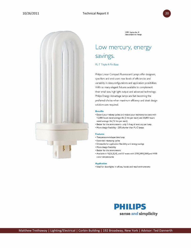
Type CR1:
Lamp: PL-T 42W Fluorescent
Ballast: Electronic

10/26/2011 Technical Report II 16
Matthew Trethaway | Lighting/Electrical | Corbin Building | 192 Broadway, New York | Advisor: Ted Dannerth

10/26/2011 Technical Report II 17
Matthew Trethaway | Lighting/Electrical | Corbin Building | 192 Broadway, New York | Advisor: Ted Dannerth

10/26/2011 Technical Report II 18
Matthew Trethaway | Lighting/Electrical | Corbin Building | 192 Broadway, New York | Advisor: Ted Dannerth

10/26/2011 Technical Report II 19
Matthew Trethaway | Lighting/Electrical | Corbin Building | 192 Broadway, New York | Advisor: Ted Dannerth
10/26/2011 Technical Report II 20
Matthew Trethaway | Lighting/Electrical | Corbin Building | 192 Broadway, New York | Advisor: Ted Dannerth

10/26/2011 Technical Report II 21
Matthew Trethaway | Lighting/Electrical | Corbin Building | 192 Broadway, New York | Advisor: Ted Dannerth
10/26/2011 Technical Report II 22
Matthew Trethaway | Lighting/Electrical | Corbin Building | 192 Broadway, New York | Advisor: Ted Dannerth

10/26/2011 Technical Report II 23
Matthew Trethaway | Lighting/Electrical | Corbin Building | 192 Broadway, New York | Advisor: Ted Dannerth

10/26/2011 Technical Report II 24
Matthew Trethaway | Lighting/Electrical | Corbin Building | 192 Broadway, New York | Advisor: Ted Dannerth

10/26/2011 Technical Report II 25
Matthew Trethaway | Lighting/Electrical | Corbin Building | 192 Broadway, New York | Advisor: Ted Dannerth

10/26/2011 Technical Report II 26
Matthew Trethaway | Lighting/Electrical | Corbin Building | 192 Broadway, New York | Advisor: Ted Dannerth