TECHNICAL APPROVAL ACCORDING TO TL/TP FÜ … · TECHNICAL APPROVAL ACCORDING TO TL/TP ... Proof of...
42
GIRDER GRID JOINTS (noise reduction included/not included) TECHNICAL APPROVAL ACCORDING TO TL/TP FÜ (Status 03/05) according to the requirements of the: Federal Ministry for Traffic, Construction and Development of Towns Department Road Construction, Road Traffic / Resort S 18 Robert-Schuman-Platz 1 D-53175 Bonn Checker: External Monitoring: German Federal Materials Testing Institute Dipl.-Ing. Winfried Neumann University Stuttgart Homertstr. 10 Pfaffenwaldring 32 D-58091 Hagen - Dahl D-70569 Stuttgart
Transcript of TECHNICAL APPROVAL ACCORDING TO TL/TP FÜ … · TECHNICAL APPROVAL ACCORDING TO TL/TP ... Proof of...

GIRDER GRID JOINTS (noise reduction included/not included)
TECHNICAL APPROVAL ACCORDING TO TL/TP FÜ
(Status 03/05)
according to the requirements of the:
Federal Ministry for Traffic, Construction and Development of Towns
Department Road Construction, Road Traffic / Resort S 18 Robert-Schuman-Platz 1
D-53175 Bonn
Checker: External Monitoring:
German Federal Materials Testing Institute Dipl.-Ing. Winfried Neumann University Stuttgart Homertstr. 10 Pfaffenwaldring 32 D-58091 Hagen - Dahl D-70569 Stuttgart

AUTHOR :
CONSTR. : CARRIAGEWAYS AND BRIDGES DATE: 1.05.2007
CONS. PART : GIRDER GIRD EXPANSION JOINTS TYPE D160 TO 640
BLOCK : DOCUMENTATION WITH TECHNICAL APPROVAL NOTE
METHOD : TECHNICAL APPROVAL ACC. TO TL/TP-FÜ (STAND: 03/05)
ARCHIVE NO.
Technical approval Nr. 07/07 vom 22.11.07
This documentation is the property of MAURER SÖHNE GmbH & Co. KG. Any reproduction – also in extracts - only upon approval. Formats and contents are copyrighted!
M a n u a l
CONTENTS
Section Title Page
0. Field of Application 1 1. Persons in Charge 1
1.1 Applicant and Operator 1 1.2 Producer of the Expansion Joint 1 1.3 Producer of Special Components 1 1.4 Quality Assurance 2 1.5 Approval and Tests 2 1.6 Producer's declaration 2
2. Description of the System 3 2.1 General 3 2.2 Types D160-640 3-4 2.3 Types DT160-240 5 2.4 Force Transfer of the Wheel Loads 5 2.5 Elastic Support of the Joists 6 2.6 Anchorage 6 2.7 Sealing Profile 6 2.8 Noise reduction 7-8
3. Notes for the User 9 3.1 Checklist for Planning and Inspection 9 3.2 Overview of the Allowed Movements within the Scope of the Technical Approval 10-11 3.3 Allowed Construction Lengths Using Laterally Fastened Bearings 11-12 3.4 Transverse Displacement in Types DT160 and DT240 without Laterally Fastened Bearings 12-13 3.5 Recess-sizes 14 3.6 Anchorage powers 15
4. Construction Requirements for Technical Approved Expansion Joints 16 4.1 Allowed Joist-interspaces and the Position of the Butt Joints 16 4.2 Arrangement of Parapet Units 17 4.3 Factory Provided Corrosion Protection 18
5. Installation Instruction 19 5.1 Delivery 19 5.2 Assembly and Adjoining to Supporting Structure with Concrete Structural Members 19-22 5.3 Anchorage in cap area 22 5.4 Procedure for Bridges with Steel Road Surfaces 23 5.5 Control of the Assembly Dimensions 23-24 5.6 Sealing the Construction 24 5.7 Further Instructions 25 5.8 Site joints 26-28
Appendix Certificate of acceptance / Protocol of mounting 29
6. Instructions for Maintenance, Preservation and Exchange of Wear and Tear Elements 30 6.1 Accessibility 30 6.2 Constructional Elements Subjected to Continuous Checking 31-32 6.3 Replacing the Sealing Elements 32 6.4 Replacing the Wear and Tear Elements from above 33
7. Construction Plans and Parts Lists 34 Enclosures Six construction plans
Inspection Report (2 pages)

AUTHOR :
CONSTR. : CARRIAGE WAYS AND BRIDGES DATUM: 1.05.2007
CONS. PART : GIRDER GIRD EXPANSION JOINTS TYPE D160 TO 640 TO DT160 TO DT240
BLOCK : 1 – PERSON IN CHARGE PAGE: 1
METHOD : TECHNICAL APPROVAL ACCORDING TO TL/TP-FÜ (STATUS: 03/05)
ARCHIVE NO.
Technical approval No. 07/07 of 22.11.07
This documentation is the property of MAURER SÖHNE GmbH & Co. KG. Any reproduction – also in extracts - only upon approval. Formats and contents are copyrighted!!
0. Field of Application Due to the implementation of the Version 5/07 the hitherto valid Version of November 20, 2002 is now void. The technical approval covers Construction of frequently repeated methods of construction. Currently there are the following limitations of the range of use to be considered: - At the gap, the superstructure in the expansion joints type D160-D640 must be leaded in a single way, for example by a one-way bearing - In laterally elastic bearing expansion, joints type DT160/240 may be adjustable under consideration of
the requirements in paragraph 3.2 - The carriageway may not exceed 10% slope orthogonal. - The carriageway may not exceed 6% slope in the direction of the joint up to type D480, and 3% in
larger types - Allowed displacements according to Table 3.2 have to be maintained. - According to the ground plan, direction changes of the joint design are allowed only between two parapet units. - Geometrical direction changes of lamellas in expansion joint types D/DT 160 are permitted as shown by Drawing 6. - For noise reduction in the range 60° ≤ α ≤ 120° rhombus elements may be used. Deviations from the above limitations and subsequent specifications are possible, but they require a test for each single case separately. 1. Persons in Charge 1.1 Applicant and Operator
MAURER SÖHNE GmbH & Co. KG Technical Bureau Munich Frankfurter Ring 193 Dr. Braun, Mr. Volk 80807 Munich 1.2 Manufacturer of the Expansion Joint
MAURER SÖHNE GmbH & Co. KG
Technical Bureaus: Manufacturing sites Installation crews Frankfurter Ring 193 80807 Munich
Frankfurter Ring 193 80807 Munich
Frankfurter Ring 193 80807 Munich
Zum Holzplatz 2 44536 Lünen
Zum Holzplatz 2 44536 Lünen
Kamenzer Str. 53 02994 Bernsdorf
Kamenzer Str. 53 02994 Bernsdorf
Kamenzer Str. 53 02994 Bernsdorf
1.3 Manufacturer of Special Components
See "The List of approved suppliers" in the appendix of the companies' work instruction QSA 1.810 in the current version.

AUTHOR :
CONSTR. : CARRIAGE WAYS AND BRIDGES DATUM: 1.05.2007
CONS. PART : GIRDER GIRD EXPANSION JOINTS TYPE D160 TO 640 TO DT160 TO DT240
BLOCK : 1 – PERSON IN CHARGE PAGE: 2
METHOD : TECHNICAL APPROVAL ACCORDING TO TL/TP-FÜ (STATUS: 03/05)
ARCHIVE NO.
Technical approval No. 07/07 of 22.11.07
This documentation is the property of MAURER SÖHNE GmbH & Co. KG. Any reproduction – also in extracts - only upon approval. Formats and contents are copyrighted!!
1.4 Quality Assurance
QS-System The Quality-Management-System meets the DIN EN ISO 9001 standards. It was certified by DVS-Zert. Monitoring The Monitoring is divided into external and internal supervision. The documents and working instructions that form the basis of this TECHNICAL APPROVAL will be tested on their compliance with these regulations. Responsible for the External Monitoring is the
German Federal Materials Testing Institute of the University of Stuttgart Pfaffenwaldring 32/ D-70569 Stuttgart
1.5 Approvals and verifications Approvals for Welding
Factory Munich "The Extensive Proof of Suitability" according to DIN 18800 Part 7, DIN 15018 (DIN 18809 included in DIN 15018), DIN 4099 and DS 804 Factory Bernsdorf "The Extensive Proof of Suitability" according to DIN 18800 Part 7, DIN 4099 and DS 804 (DIN 18809) Branch Office Lünen "The Extensive Proof of Suitability" according to DIN 18800 Part 7, DIN 18809, DIN 4099 and DS 804 Approval of factory welders
The condition required to obtain an Approval is a Licence according to DIN EN 287-1. Approval of site welders According to component demands, only welders with a valid verification certificate according to DIN EN 287-1 and site welder’s verification according to DIN 4099 are deployed. The related verification is available on the site. For blade welding with a copper jaw touch according to QSA 1.510, Point 2.1 "Site welding of the blade" a special Certificate of Qualification has to be presented. 1.6 Producer's statement MAURER SÖHNE GmbH & Co. KG declare herewith • Compliance with the design conditions of all documents with the test certificates, listed in the index from May 1,
2007 • Compliance with quality assurance standards listed in the supervision contract from March 1, 2002. Munich, February 1, 2007 Company Management Technical Bureau

AUTHOR :
CONSTR. : CARRIAGE WAYS AND BRIDGES DATUM: 1.05.2007
CONS. PART : GIRDER GIRD EXPANSION JOINTS TYPE D160 TO 640 TO DT160 BIS DT240
BLOCK : 3 – NOTICES FOR THE USER PAGE: 3
METHOD : TECHNICAL APPROVAL ACCORDING TO TL/TP-FÜ (STATUS: 03/05)
ARCHIV NO.
Technical approval No. 07/07 of 22.11.07
This documentation is the property of MAURER SÖHNE GmbH & Co. KG. Any reproduction – also in extracts - only upon approval. Formats and contents are copyrighted!
2. Description of the System 2.1 General At each MAURER-Girder Grid expansion joint each lamella is rigidly welded to the assigned cross bars. So an internal relocatable girder grid is provided. This expansion joint is to be applied in situations where, at both joint edges, i.e. at the abutment and at the superstructure, there is enough space or enough space can be provided in which to install the joist- box. The technical approval includes the types D160-D640 and DT160-DT240, where the construction forms D and DT differ with regard to their control system and the joist/lamella welding connection. 2.2 Types D160-640 The joists are positioned according to the moving direction of the structure. Planned moving components other than those given are not going to be absorbed. For this reason bearings have to be placed under the movable superstructure in order to compensate the rectangular movement effectively..
MAURER-girder grid expansion joints always adapt to the deformation of the structure. Control springs, positioned between joists or between the joist and the sidewall of the joist box, provide an equal distribution of the whole movement to each joint gap. Steel stops on joists prevent the opening of individual gaps for more than 80 mm.

AUTHOR :
CONSTR. : CARRIAGE WAYS AND BRIDGES DATUM: 1.05.2007
CONS. PART : GIRDER GIRD EXPANSION JOINTS TYPE D160 TO 640 TO DT160 BIS DT240
BLOCK : 3 – NOTICES FOR THE USER PAGE: 4
METHOD : TECHNICAL APPROVAL ACCORDING TO TL/TP-FÜ (STATUS: 03/05)
ARCHIV NO.
Technical approval No. 07/07 of 22.11.07
This documentation is the property of MAURER SÖHNE GmbH & Co. KG. Any reproduction – also in extracts - only upon approval. Formats and contents are copyrighted!
The control springs consist of mostly closed cell Polyurethane, a suitable material for dynamic and shock stressed spring elements. The high allowed deformation (up to 80 % pressure deformation, relating to the uncompressed basic position) enables the production of elements with large allowed spring travel at small dimensions. The self absorbability of the material at the same time provides for oscillation and shock damping of dynamic stressed constructional parts. The way of alignment of block pins for attachment of the control springs onto joists causes a compression of springs as the gap opens. At each opening state the springs are tense; the pressure pre-tensioning is lowest when the gap is closed. The advantages of this control system are: •Adaptability to production tolerances •Low accident sensitivity •Durability •Insensitivity to movement enforcements •Noise damping •Possibility of expanding individual gaps for maintenance works

AUTHOR :
CONSTR. : CARRIAGE WAYS AND BRIDGES DATUM: 1.05.2007
CONS. PART : GIRDER GIRD EXPANSION JOINTS TYPE D160 TO 640 TO DT160 BIS DT240
BLOCK : 3 – NOTICES FOR THE USER PAGE: 5
METHOD : TECHNICAL APPROVAL ACCORDING TO TL/TP-FÜ (STATUS: 03/05)
ARCHIV NO.
Technical approval No. 07/07 of 22.11.07
This documentation is the property of MAURER SÖHNE GmbH & Co. KG. Any reproduction – also in extracts - only upon approval. Formats and contents are copyrighted!
2.3 Types DT160-240 The joists are aligned in the direction of movement of the structure. Other planned moving components of + 30 mm parallel to joint axis are going to be absorbed. The pressure-thrust-springs at the joint's edges control the constant distance of the beams among themselves according to the total width of the joint gap.
2.4 Transmission of wheel load Lamellas are subject to direct wheel loads. Because of eccentric raiding wheel loads, based internal force variables are transferred through the bars over welded joints to the cross bars (joists). From there they are transferred over the bearing elements and control springs into the gap edges.

AUTHOR :
CONSTR. : CARRIAGE WAYS AND BRIDGES DATUM: 1.05.2007
CONS. PART : GIRDER GIRD EXPANSION JOINTS TYPE D160 TO 640 TO DT160 BIS DT240
BLOCK : 3 – NOTICES FOR THE USER PAGE: 6
METHOD : TECHNICAL APPROVAL ACCORDING TO TL/TP-FÜ (STATUS: 03/05)
ARCHIV NO.
Technical approval No. 07/07 of 22.11.07
This documentation is the property of MAURER SÖHNE GmbH & Co. KG. Any reproduction – also in extracts - only upon approval. Formats and contents are copyrighted!
2.5 Elastic support of joists (cross bars) Cross bars at their structure edges are spring elastically supported on slide bearings. The cross bars lift-off from slide bearings within the cross bar box (joist-box) is prevented by means of pre-stressed slide springs arranged above the cross bars (joists). Through this elastic bearing the momentum of the wheels is damped when transferred to the absorbent elements of the cross section or to the neighbouring anchor parts. The arrangement of the elastomer bearing elements between all relatively converging components prevents any metal-to-metal contact, and assures at the same time high damping of noises within the vulcanised rubber elements. The elastomer bearing elements allow rotations about all three axes, whereby for instance unplanned restraint forces can be prevented. . 2.6 Anchorage Edge profiles are anchored with non stretchable anchor plates and welded round steel clamps in the concrete of the construction. The cross bar boxes (joist-boxes) have welded head bolt dowels to connect to the neighbouring concrete. In steel bridges the edge construction is mounted on steel consoles or support holders parallel to the end cross beam. . 2.7 Sealing profile The bulbous-shaped EPDM strip is a waterproof and pullout seal and is installed in a claw in the edge beam and centre beams without the need for additional clamping bars. At the thickened places at the edge of the seal expansion joints a web is formed, which ends as a beaded rim. When the seal expansion joint is placed into the steel profile, the thickened part presses, using the wedging force, against the steel profile. By this means, in addition to a form-locking connection, a friction-fitted Seal-/Steel profile contact is provided. At the same time the formed web with beaded rim acts as a lock which prevents jumping out in the case of dragging forces. The sealing element is set below the road surface level, and thus protected against direct wheel- or snowplough-contact. The admissible displacement of the sealing profile rectangular in the direction to the gap is 65 mm. With its preformed articulated section it is possible to move the seal strip in the direction of the carriageway without any appreciable strain. The admissible displacement in the direction to the gap of ±40 mm causes a strain in the sealing profile. Sealing elements can be replaced from above with a pry bar when the individual gaps are ≥ 25 mm. Whenever rhombic elements are used for the reduction of noise, the individual gap widths must be ≥ 60 mm. Gap width can be enlargened by moving the lamellas.
AUTHOR :
CONSTR. : CARRIAGE WAYS AND BRIDGES DATUM: 1.05.2007
CONS. PART : GIRDER GIRD EXPANSION JOINTS TYPE D160 TO 640 TO DT160 BIS DT240
BLOCK : 3 – NOTICES FOR THE USER PAGE: 7
METHOD : TECHNICAL APPROVAL ACCORDING TO TL/TP-FÜ (STATUS: 03/05)
ARCHIV NO.
Technical approval No. 07/07 of 22.11.07
This documentation is the property of MAURER SÖHNE GmbH & Co. KG. Any reproduction – also in extracts - only upon approval. Formats and contents are copyrighted!
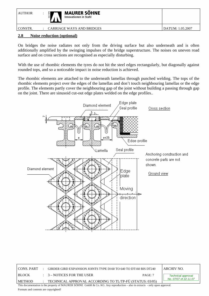
2.8 Noise reduction (optional) On bridges the noise radiates not only from the driving surface but also underneath and is often additionally amplified by the swinging impulses of the bridge superstructure. The noises on uneven road surface and on cross sections are recognised as especially disturbing. With the use of rhombic elements the tyres do not hit the steel edges rectangularly, but diagonally against rounded tops, and so a noticeable impact in noise reduction is achieved. The rhombic elements are attached to the underneath lamellas through punched welding. The tops of the rhombic elements project over the edges of the lamellas and don’t touch neighbouring lamellas or the edge profile. The elements partly cover the neighbouring gap of the joint without building a passing through gap on the joint. There are sinusoid cut-out edge plates welded on the edge profiles..

AUTHOR :
CONSTR. : CARRIAGE WAYS AND BRIDGES DATUM: 1.05.2007
CONS. PART : GIRDER GIRD EXPANSION JOINTS TYPE D160 TO 640 TO DT160 BIS DT240
BLOCK : 3 – NOTICES FOR THE USER PAGE: 8
METHOD : TECHNICAL APPROVAL ACCORDING TO TL/TP-FÜ (STATUS: 03/05)
ARCHIV NO.
Technical approval No. 07/07 of 22.11.07
This documentation is the property of MAURER SÖHNE GmbH & Co. KG. Any reproduction – also in extracts - only upon approval. Formats and contents are copyrighted!
This gives a noise reduction of approximately 7 dB for cars and trucks compared to usual joints made with lamellas crossed over rectangular to the longitudinal direction of joint (ε = 90°). By using rhombic elements the carriageway geometry travelled on is also changed. The influence on the wheel load spreading at the expansion joints was technically experimentally tested at the TU-Munich, with comparative analysis of results for the lamellas with and without rhombic elements. The truck wheel was put centric above the middle lamella and, in the second part of the experiment between two lamellas. Additionally the load position of 5 different gap widths was tested. The results showed that the lamellas, both with and without the rhombic elements, had to absorb almost the same wheel load. In their present forms there are also no static relevant differences. All other known design concepts for expansion joints have full validity for the rhombic elements too. The tests showed no differences in traffic security concerning the tyre grip between the constructions of lamellas with and without rhombic elements at non profiled surfaces. As the rhombic elements are hammer forged the driving surfaces obtain an additionally chequered structure. This provides a better grip between the wheel and the rhombic element, and it is carried out as an advancement of technical traffic security regardless of positive test results. As the rhombic elements are pouch-welded, there is a non-welded gap on the outer edge of the contact surface. To prevent corrosion damages, the following method was developed to provide adequate sealing.
The gap is sealed to the outer edge by a special sealing material. Silicon mass is pressed through a borehole into a sealing groove in the welded construction. Two control gaps enable the operator to check whether there was enough sealing mass injected. After this procedure the borehole is closed with a smashed in cylinder bolt. The hardening of silicon prevents lateral leaking later on.

AUTHOR :
CONSTR. : CARRIAGE WAYS AND BRIDGES DATUM: 1.05.2007
CONS. PART : GIRDER GIRD EXPANSION JOINTS TYPE D160 TO 640 TO DT160 BIS DT240
BLOCK : 3 – NOTICES FOR THE USER PAGE: 9
METHOD : TECHNICAL APPROVAL ACCORDING TO TL/TP-FÜ (STATUS: 03/05)
ARCHIV NO.
Technical approval No. 07/07 of 22.11.07
This documentation is the property of MAURER SÖHNE GmbH & Co. KG. Any reproduction – also in extracts - only upon approval. Formats and contents are copyrighted!
3. Notes for the User 3.1 Checklist for the Planning and Inspection Hereunder all items are specified that must be observed with the structural planning and examination:
1 Field of application 1.1 Review of the ancillary conditions for the application area and the choice of the type of expansion
joint. 2 Movements 2.1 Calculation of movements of the expansion joint from rotation and displacement of neighbouring
components due to Temperature Shrinkage and Creep Lifting during bearing removal Braking/starting up Displacement of fixed points Elasticity of the foundation Other Effects
2.2 Determination of the most unfavourable moving combinations at the expansion joint 2.3 Selection of expansion joint considering the allowable movement according to specifications in
the Tables of part 3.2 2.4 Check of final cross girder deformations in respect of specifications according to ZTV-ING 3 Loads 3.1 Check whether the loads affecting the expansion joint are covered by load estimates according to
TL/TP-FÜ (03/05) (special vehicles, inspection devices) 4 Pre-adjustment 4.1 Determination of the scheduled installation temperature and the appropriate pre-setting
rectangular and parallel to the joint 4.2 Defining the change of dimensions of pre-adjustment in mm/°C 5 Recesses 5.1 Determination of the size und configuration of recesses according to Part 3.5 for the anchoring of
the expansion joint 5.2 In special cases: Dimensioning with approval of company Maurer Söhne 6 Anchorage 6.1 Planning of connecting reinforcement under consideration of the loads given in Part 3.6 6.2 Adjustment of reinforcements to the installation situation of the expansion joints 6.3 Designing of reinforcements capable of trouble-free mounting with anchoring in connecting
brackets of the expansion joint 7 Handling by the company MAURER SÖHNE 7.1 Preparing overview and detailed drawings specific for the structure 7.2 Examination and proof of the geometrical operation conditions 7.3 Adaptation of joist arrangement to special construction requirements (clamping elements,
recesses)

AUTHOR :
CONSTR. : CARRIAGE WAYS AND BRIDGES DATUM: 1.05.2007
CONS. PART : GIRDER GIRD EXPANSION JOINTS TYPE D160 TO 640 TO DT160 BIS DT240
BLOCK : 3 – NOTICES FOR THE USER PAGE: 10
METHOD : TECHNICAL APPROVAL ACCORDING TO TL/TP-FÜ (STATUS: 03/05)
ARCHIV NO.
Technical approval No. 07/07 of 22.11.07
This documentation is the property of MAURER SÖHNE GmbH & Co. KG. Any reproduction – also in extracts - only upon approval. Formats and contents are copyrighted!
3.2 Overview of the Allowed Movements Determined Within the Scope of the Technical Approval - Types D160-D640 All acceptable movements may arise in any combination within the given tolerance areas. For the angles ϕx, ϕz and the displacement uz following formulae are valid.
n
Number of sealing profiles
type ux [mm]
Total expansion
width
uz [mm]
s=27,5 mm
uz [mm]
s=37,5 mm
ϕx
s=37,5 mm B=15 m
ϕy,stat
ϕy,dyn
ϕz
s=37,5 mm B=15 m
α [°]
β [°]
2 D160 130 ± 17,7 ± 19,2 ± 0,147° ± 0,497°
3 D240 195 ± 26,6 ± 28,8 ± 0,220° ± 0,745° 90°±60°
4 D320 260 ± 35,4 ± 38,5 ± 0,293° ± 0,993°
5 D400 325 ± 44,3 ± 48,1 ± 0,367° ± 4,311° ± 1,031° ± 1,241° aany
6 D480 390 ± 53,2 ± 57,7 ± 0,440° ± 1,489° 90°±45°
7 D560 455 ± 62,0 ± 67,3 ± 0,513° ± 1,737°
8 D640 520 ± 70,9 ± 76,9 ± 0,587° ± 1,985° n... Number of the sealing profiles u... Movement direction of the superstructure ends (apply on guided bearings) ux... Movement component rectangular to the gap axis (n × 95 mm) uy.. Movement component parallel to gap axis (±(±n × 50 mm (only for sealing profiles)) uz.. Height offset of the edge profile in z-direction as geometrical sustainable (±0,0754 × n × (90 + e[mm])) Limit in special cases of dimensioning (for example earth quake loads)
ϕx... Rotation about x-axis rectangular to the gap (±arctan ((2 × 0,0754 × n × (90 + e[mm]) / B[mm]))
ϕy... Rotation of cross bar bearings about y-axis (gap axis)
ϕz... Rotation about the z-axis at the driving surface (±arctan ((ux,zul - ux,vorh) × 2 / B))
α... Angle between gap axis y and moving direction u β... Angle between gap axis y and carriage way axis s... Single gap width between the lamellas or between edge profile and lamella B... Gap length in y-direction If allowed movements are exceeded, there has to be an additional verification in each special single case.
AUTHOR :
CONSTR. : CARRIAGE WAYS AND BRIDGES DATUM: 1.05.2007
CONS. PART : GIRDER GIRD EXPANSION JOINTS TYPE D160 TO 640 TO DT160 BIS DT240
BLOCK : 3 – NOTICES FOR THE USER PAGE: 11
METHOD : TECHNICAL APPROVAL ACCORDING TO TL/TP-FÜ (STATUS: 03/05)
ARCHIV NO.
Technical approval No. 07/07 of 22.11.07
This documentation is the property of MAURER SÖHNE GmbH & Co. KG. Any reproduction – also in extracts - only upon approval. Formats and contents are copyrighted!
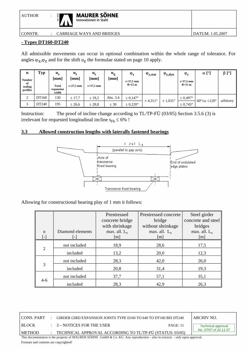
- Types DT160-DT240 All admissible movements can occur in optional combination within the whole range of tolerance. For angles ϕx,ϕz and for the shift uz the formulae stated on page 10 apply.
n
Number of
sealing profiles
Typ ux [mm]
Total
expansion width
uz [mm]
s=27,5 mm
uz [mm]
s=37,5 mm
uq [mm]
ϕx
s=37,5 mm B=15 m
ϕy,stat
ϕy,dyn
ϕz
s=37,5 mm B=15 m
α [°]
β [°]
2 DT160 130 ± 17,7 ± 19,2 Abs. 3.4 ± 0,147° ± 0,497°
3 DT240 195 ± 26,6 ± 28,8 ± 30 ± 0,220° ± 4,311° ± 1,031°
± 0,745° 60°≤α ≤120° arbitrary
Instruction: The proof of incline change according to TL/TP-FÜ (03/05) Section 3.5.6 (3) is irrelevant for requested longitudinal incline sFb ≤ 6% ! 3.3 Allowed construction lengths with laterally fastened bearings
Allowing for constructional bearing play of 1 mm it follows:
Prestressed concrete bridge with shrinkage
Prestressed concrete bridge
without shrinkage
Steel girder concrete and steel
bridges n Diamond elements max. all. Lq max. all. Lq max. all. Lq [-] [-] [m] [m] [m]
not included 18,9 28,6 17,5 2
included 13,2 20,0 12,3
not included 28,3 42,0 26,0 3
included 20,8 31,4 19,3
not included 37,7 57,1 35,1 4-6
included 28,3 42,9 26,3
AUTHOR :
CONSTR. : CARRIAGE WAYS AND BRIDGES DATUM: 1.05.2007
CONS. PART : GIRDER GIRD EXPANSION JOINTS TYPE D160 TO 640 TO DT160 BIS DT240
BLOCK : 3 – NOTICES FOR THE USER PAGE: 12
METHOD : TECHNICAL APPROVAL ACCORDING TO TL/TP-FÜ (STATUS: 03/05)
ARCHIV NO.
Technical approval No. 07/07 of 22.11.07
This documentation is the property of MAURER SÖHNE GmbH & Co. KG. Any reproduction – also in extracts - only upon approval. Formats and contents are copyrighted!
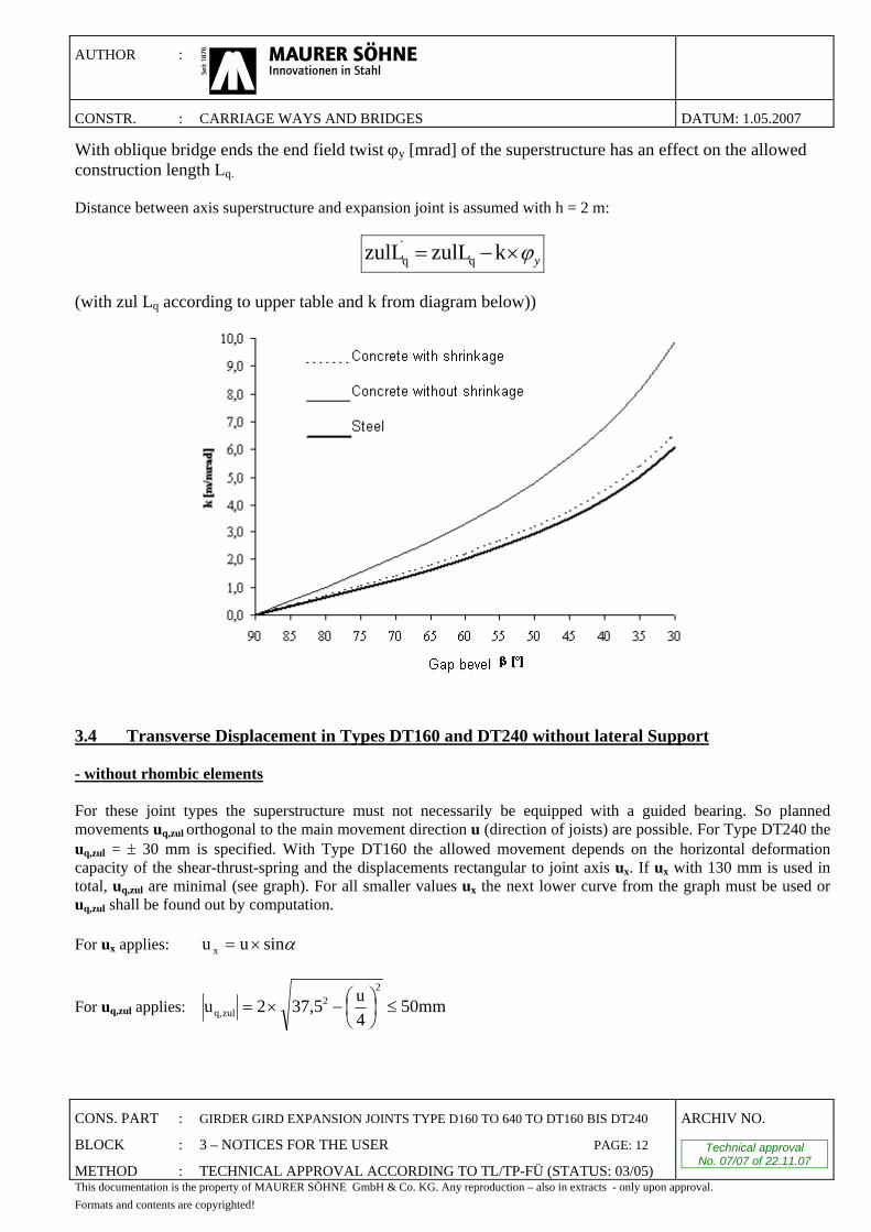
With oblique bridge ends the end field twist ϕy [mrad] of the superstructure has an effect on the allowed construction length Lq. Distance between axis superstructure and expansion joint is assumed with h = 2 m:
yϕ×−= kzulLzulL q`q
(with zul Lq according to upper table and k from diagram below))
3.4 Transverse Displacement in Types DT160 and DT240 without lateral Support - without rhombic elements For these joint types the superstructure must not necessarily be equipped with a guided bearing. So planned movements uq,zul orthogonal to the main movement direction u (direction of joists) are possible. For Type DT240 the uq,zul = ± 30 mm is specified. With Type DT160 the allowed movement depends on the horizontal deformation capacity of the shear-thrust-spring and the displacements rectangular to joint axis ux. If ux with 130 mm is used in total, uq,zul are minimal (see graph). For all smaller values ux the next lower curve from the graph must be used or uq,zul shall be found out by computation. For ux applies: αsinuu x ×=
For uq,zul applies: 50mm4u37,52u
22
zulq, ≤⎟⎠⎞
⎜⎝⎛−×=

AUTHOR :
CONSTR. : CARRIAGE WAYS AND BRIDGES DATUM: 1.05.2007
CONS. PART : GIRDER GIRD EXPANSION JOINTS TYPE D160 TO 640 TO DT160 BIS DT240
BLOCK : 3 – NOTICES FOR THE USER PAGE: 13
METHOD : TECHNICAL APPROVAL ACCORDING TO TL/TP-FÜ (STATUS: 03/05)
ARCHIV NO.
Technical approval No. 07/07 of 22.11.07
This documentation is the property of MAURER SÖHNE GmbH & Co. KG. Any reproduction – also in extracts - only upon approval. Formats and contents are copyrighted!
If allowed movements are exceeded, there has to be an additional verification in each special single case. - with rhombic elements As rhombic elements are also scheduled for expansion joints with regular transverse displacement, tests are made to find out which circumstances have to be kept to avoid possible tensions. Presuming that the minimum gap position is always smaller than the mid position , we get the following equation for the allowed transversal movement:
( ) ⎥⎦
⎤⎢⎣
⎡Δ××−⎟
⎠
⎞⎜⎝
⎛−×+−−×±= TL5s
5,3220116nu minzulq, α
where: uq,zul (planned transversal movement u) n (number of sealing profiles) smin (minimal gap) L = 12000 mm (accordingly to the assumed maximum value) α = 12×10-6 1/K (coefficient of expansion for steel) ΔT = 47,5 K (maximum temperature difference with steel and concrete steel
bridges according to an installation temperature of 10°C)
smin= 5 mm smin= 37,5 mmn ± uq,zul ± uq,zul [-] [mm] [mm]
2 1 41 3 5 30*
Intermediate values can be interpolated.
*) Structural maximum value

AUTHOR :
CONSTR. : CARRIAGE WAYS AND BRIDGES DATUM: 1.05.2007
CONS. PART : GIRDER GIRD EXPANSION JOINTS TYPE D160 TO 640 TO DT160 BIS DT240
BLOCK : 3 – NOTICES FOR THE USER PAGE: 14
METHOD : TECHNICAL APPROVAL ACCORDING TO TL/TP-FÜ (STATUS: 03/05)
ARCHIV NO.
Technical approval No. 07/07 of 22.11.07
This documentation is the property of MAURER SÖHNE GmbH & Co. KG. Any reproduction – also in extracts - only upon approval. Formats and contents are copyrighted!
3.5 Recess-sizes
MAURER expansion joint
Structural dimensions Concrete recess dimensions Concrete joint dimensions
n Typ α [°]
a [mm]
b [mm]
c [mm]
d [mm]
h*
[mm] tF
[mm] t1,G
[mm] t2,G
[mm] fmin [mm]
fmax [mm]
lF [mm]
lG [mm]
DT160 90°-60° 200 175 300 90°-45° 216 340 2 D160 44°-30°
150 217 236 360 350 335 335 150 200 850 820
DT240 311 205 330 90°-60° 226 350 59°-45° 297 246
255
370 3 D240 44°-30°
270
330 256 380
430 355 355 240 320 1100 950
90°-60° 246 370 59°-45° 377 266 390 4 D320 44°-30°
390 407 276 400
520 365 365 350 440 1390 1080
90°-60° 509 266 390 650 1760 5 D400 59°-45° 510 525 286
275
410 680 375 375 460 560 1820 1210
90°-60° 588 286 410 745 2060 6 D480 59°-45° 630 606 306 430 760 385 400 570 680 2090 1340
90°-50° 682 306 430 800 2280 7 D560 49°-45° 750 687 326 450 850 395 450 680 800 2380 1470
90°-60° 749 306 430 890 2570 8 D640 59°-45° 870 767 326
285
450 940 405 500 790 920 2670 1600
• all dimensions apply rectangular to the joint axis y • *) if rhombic elements are part of the construction, the value for h has to be increased by 20mm! • n = number of sealing profiles • a, f and l apply for the setting dimension e = 30 mm for each joint gap. If dimension e differs, it has to be corrected by Δe. • Recesses for footway joists and cable conduits have to be considered individually. •due to the specific design of the construction, in special cases smaller recesses are possible. As long as the dimensions of the
steel construction remain unchanged, suchlike deviation requires no special approval but falls within the competence of the bridge designer and the engineer competent for testing of the structure (consider the capability for concreting).
•Consider specifications given in Part 6.1.
AUTHOR :
CONSTR. : CARRIAGE WAYS AND BRIDGES DATUM: 1.05.2007
CONS. PART : GIRDER GIRD EXPANSION JOINTS TYPE D160 TO 640 TO DT160 BIS DT240
BLOCK : 3 – NOTICES FOR THE USER PAGE: 15
METHOD : TECHNICAL APPROVAL ACCORDING TO TL/TP-FÜ (STATUS: 03/05)
ARCHIV NO.
Technical approval No. 07/07 of 22.11.07
This documentation is the property of MAURER SÖHNE GmbH & Co. KG. Any reproduction – also in extracts - only upon approval. Formats and contents are copyrighted!
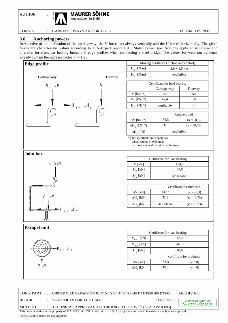
3.6 Anchoring powers Irrespective of the inclination of the carriageway, the V forces act always vertically and the H forces horizontally. The given forces are characteristic values according to DIN-Expert report 101. Stated power specifications apply at same size and direction for cross bar bearing boxes and edge profiles when connecting a steel bridge. The values for wear out evidence already contain the increase factor γE = 1,25.
Edge profile
Carriage way Footway
Δ
Δ
Certificate for load bearing V [kN] 134,0 Hx [kN] 47,0
Hy [kN] 47,4×tanα
Certificate for tiredness
ΔV [kN] 130,7 (κ = -0,3) ΔHx [kN] 31,5 (κ = -0,73)
ΔHy [kN] 31,5×tanα (κ = -0,73)
Joint box
Δ
Δ
Parapet unit
Δ
Δ
Certificate for load bearing Vmax [kN] 42,2
Vmin [kN] -41,7
Hy [kN] 40,6
certificate for tiredness ΔV [kN] -31,3 (κ = 0) ΔHy [kN] 30,5 (κ = 0)
Moving resistance (friction and control) Hx [kN/m] 3,0 + 1,5 × n
Hy [kN/m] negligible
Certificate for load bearing Carriage way Footway
V [kN] *) 140 50 Hx [kN] *) 47,4 3,0
Hy [kN] *) negligible -
Fatigue proof ΔV [kN] *) 136,5 (κ = -0,3) ΔHx [kN] *) 32 (κ = -0,73)
ΔHy [kN] negligible
*) the specified forces apply for wheel widths b=0,60 m at carriage way and b=0,40 m at footway

CONS. PART : GIRDER GIRD EXPANSION JOINTS TYPE D160 TO 640 TO DT160 BIS DT240
BLOCK : 3 – NOTICES FOR THE USER PAGE: 16
METHOD : TECHNICAL APPROVAL ACCORDING TO TL/TP-FÜ (STATUS: 03/05)
ARCHIV NO.
Technical approval No. 07/07 of 22.11.07
This documentation is the property of MAURER SÖHNE GmbH & Co. KG. Any reproduction – also in extracts - only upon approval. Formats and contents are copyrighted!
AUTHOR :
CONSTR. : CARRIAGE WAYS AND BRIDGES DATUM: 1.05.2007 4. Construction Requirements for the technical approved expansion joints
4.1 Allowed cross bar interspaces and position of butt joints
*)The values for ASb have to be maintained for each neighbouring n-1 Cross bar. **)See Part 4.2
n s ASb [mm]
L [mm]
R [mm]
Smin [mm]
Smax [mm]
Tmin [mm]
Tmax [mm]
≤3% 115 500 60 370 ≤4% 118 467 65 342 ≤5% 122 433 70 313
2-6
≤6% 7-8 ≤3%
≤830 ≤1630 ≤1630
125 400 75 285

CONS. PART : GIRDER GIRD EXPANSION JOINTS TYPE D160 TO 640 TO DT160 BIS DT240
BLOCK : 3 – NOTICES FOR THE USER PAGE: 17
METHOD : TECHNICAL APPROVAL ACCORDING TO TL/TP-FÜ (STATUS: 03/05)
ARCHIV NO.
Technical approval No. 07/07 of 22.11.07
This documentation is the property of MAURER SÖHNE GmbH & Co. KG. Any reproduction – also in extracts - only upon approval. Formats and contents are copyrighted!
AUTHOR :
CONSTR. : CARRIAGE WAYS AND BRIDGES DATUM: 1.05.2007
When the bridge declination > 3% on all cross bar (joist) boxes of the carriageway a 0.,5 m long guiding profile has to be inserted additionally.
4.2 Arrangement of the Parapet Units In the movement spectrum of 105° < α < 75° all parapet units normally are swivel-mounted, but at least one parapet unit has to be rotatable. At a single gap width of e = 30 mm they are installed rectangular to the joint axis. According to TL/TP-FÜ (03/05) the vertical nominal frequency fv = 120 Hz and the horizontal nominal frequency fh = 40 Hz shall not go below. Therefore the projecting length AGes has to be limited.
n AGes [mm]
L0 [mm]
P [mm]
≤400 ≤1700 0 ≤400 ≤1700 ≤1700 ≤600 ≤1700 ≤1500
2-8
≤600 ≤1500 0 Is the clearance between the outer edge of the parapet area and the middle of the pavement steering at the kerb unit X > 2,6 m, on the outer Parapet unit a 0,5 m long guiding profile has to be inserted additionally.

CONS. PART : GIRDER GIRD EXPANSION JOINTS TYPE D160 TO 640 TO DT160 BIS DT240
BLOCK : 3 – NOTICES FOR THE USER PAGE: 18
METHOD : TECHNICAL APPROVAL ACCORDING TO TL/TP-FÜ (STATUS: 03/05)
ARCHIV NO.
Technical approval No. 07/07 of 22.11.07
This documentation is the property of MAURER SÖHNE GmbH & Co. KG. Any reproduction – also in extracts - only upon approval. Formats and contents are copyrighted!
AUTHOR :
CONSTR. : CARRIAGE WAYS AND BRIDGES DATUM: 1.05.2007 4.3 Factory Provided Corrosion Protection The corrosion protection of the constructions technically approved according to ZTV-KOR-Steel Constructions 2002 Annex A.
Corrosion protection system No. 1 Required layer thickness
Surface pre-treatment
Materials according to TL/TP-KOR-Steel Constructions 2002
Page No. GB EP-zink dust 70 µm Sa 2½
1.DB 2.DB EP(micaceous iron ore) 80 µm per DB 94/95 3.DB 4.DB
The blasting is executed in a flow through installation, the coating in airless-procedure following immediately. The protected area is shown on following drawings:

CONS. PART : GIRDER GIRD EXPANSION JOINTS TYPE D160 TO 640 TO DT160 BIS DT240
BLOCK : 3 – NOTICES FOR THE USER PAGE: 19
METHOD : TECHNICAL APPROVAL ACCORDING TO TL/TP-FÜ (STATUS: 03/05)
ARCHIV NO.
Technical approval No. 07/07 of 22.11.07
This documentation is the property of MAURER SÖHNE GmbH & Co. KG. Any reproduction – also in extracts - only upon approval. Formats and contents are copyrighted!
AUTHOR :
CONSTR. : CARRIAGE WAYS AND BRIDGES DATUM: 1.05.2007 5. Installation Instruction 5.1 Delivery The expansion joints are delivered to site completely assembled in whole lengths or section wise. Auxiliary devices support the transport, storing and installation. They keep the expansion joints in the correct installation position and render a professional loading possible. Hanging points for up and downloading are marked with colour, the installation position is marked and the total weight of each construction is stated on separate hanging plates or adhesive labels. The constructions have to be appropriately stored on site, i.e. they have to be put on suitable underlay (i.e. on square shaped timber). Damage and dirt have to be prevented through well aired canvases. The weights per linear meter specified in the following table can be taken as standard values for the crane layout.
Table: Weights per running meter for crane layout (guiding values) 5.2 Installation and connection to supporting structure in case of concrete parts The size of recesses in the structural concrete must already be defined in advance as early as at the structure planning stage according to Part 3.5 or finally according to our construction drawings, and has to be executed accordingly. Always observe the proper width of the structural gap. The recess dimensions are to be checked once again just before installing and must be corrected if necessary. The surfaces of the recesses have to be treated as working gaps according to DIN 1045.
type weight [kg/m] DT/D160 200 DT/D240 290
D320 400 D400 530 D480 680 D560 830 D640 1040

CONS. PART : GIRDER GIRD EXPANSION JOINTS TYPE D160 TO 640 TO DT160 BIS DT240
BLOCK : 3 – NOTICES FOR THE USER PAGE: 20
METHOD : TECHNICAL APPROVAL ACCORDING TO TL/TP-FÜ (STATUS: 03/05)
ARCHIV NO.
Technical approval No. 07/07 of 22.11.07
This documentation is the property of MAURER SÖHNE GmbH & Co. KG. Any reproduction – also in extracts - only upon approval. Formats and contents are copyrighted!
AUTHOR :
CONSTR. : CARRIAGE WAYS AND BRIDGES DATUM: 1.05.2007 The structural connection has to be executed in accordance with the rules of steel concrete or steel construction. A good connecting reinforcement has to be provided along the whole joint before installation. It has to be considered that normally anchoring loops at the edge profiles are placed rectangular to the joint. Expected variations from this direction are allowed only within the range of 90° ± 20°. As the anchoring reinforcement of the structure has to be parallel to the anchor loops, that has to be considered as early as at the structure planning stage and controlled on site.
The following drawing presents the standard-edge profile. It is almost of same shape for all types. The only difference is in the height H of the standing plate. Normally it reaches to the lower edge of the joist-box. To enable the attachment of shuttering plates, this plate is lengthened by 30 mm. This standard-edge profile is static equal to the construction for cross sections with a sealing profile according to Übe 1. .
∅

CONS. PART : GIRDER GIRD EXPANSION JOINTS TYPE D160 TO 640 TO DT160 BIS DT240
BLOCK : 3 – NOTICES FOR THE USER PAGE: 21
METHOD : TECHNICAL APPROVAL ACCORDING TO TL/TP-FÜ (STATUS: 03/05)
ARCHIV NO.
Technical approval No. 07/07 of 22.11.07
This documentation is the property of MAURER SÖHNE GmbH & Co. KG. Any reproduction – also in extracts - only upon approval. Formats and contents are copyrighted!
AUTHOR :
CONSTR. : CARRIAGE WAYS AND BRIDGES DATUM: 1.05.2007
A reinforcement in net or sling form has to be provided underneath the cross box as Reinforcement against split drag. See the construction plan after section 7 for appropriate data.
Picture 1: Cross section joist box The construction has to be lifted into the recess by using an adequate truck-mounted crane, then levelled to the required height according to the site engineer and assembled parallel to the longitudinal and transverse slope of the carriageway. Each construction has to be heaved into the recess by an adequate truck mounted crane, then levelled to the required height and assembled parallel according to instructions of the site engineer and built in parallel to the longitudinal and transversal slope or the carriageway. The edge profiles have to be aligned carefully along according to the ground plan and to the sheer plan. Specifications of the height position of the cross section relating to the carriageway surface from ZTV-ING have to be observed. After the carriageway crossover is aligned vertical stiffeners are welded on the sides of the cross bar box as assistant support, and the anchor slings and head bolt dowels of the cross bar box are welded with existing reinforcement. Take care that the welding between the anchor slings and reinforcement first takes place on one side only. On the other side first additional structural steel for horizontal anchoring of head bolt dowels, or at each of the first anchor slings next to the cross bar boxes is added if missing and welded with the site reinforcement, but not with the construction of the cross section. To shorten the period till loosening the installation holder as much as possible, first the welding is done only in the area next to the cross bar boxes then the installations holders are loosened, but not removed, and so additional bending strength is achieved although the possibility of motion is present. Welding the remaining anchors with the reinforcement fixes the carriageway crossover firmly in its final position.

CONS. PART : GIRDER GIRD EXPANSION JOINTS TYPE D160 TO 640 TO DT160 BIS DT240
BLOCK : 3 – NOTICES FOR THE USER PAGE: 22
METHOD : TECHNICAL APPROVAL ACCORDING TO TL/TP-FÜ (STATUS: 03/05)
ARCHIV NO.
Technical approval No. 07/07 of 22.11.07
This documentation is the property of MAURER SÖHNE GmbH & Co. KG. Any reproduction – also in extracts - only upon approval. Formats and contents are copyrighted!
AUTHOR :
CONSTR. : CARRIAGE WAYS AND BRIDGES DATUM: 1.05.2007 After the attachment of reinforcements, the construction has to bear the appearing structure movements without influence on the later binding process of the concrete. After our personnel have finished the assembly it must be checked and accepted by the construction supervisor and the completed installation of the construction has to be certified. Use the appropriate form referring to the construction. Shuttering and concreting is carried out by the construction company. The recesses must be shuttered in such a way that the scheduled dimensions are obtained at the edge beam and the joist boxes. Attention must be paid to careful and close shuttering to avoid concrete tearing into the joist boxes and the joint gap between superstructure and abutment. A sealing drainage (acc. to drawing Was 11) must be assigned for the prevention of banking behind the edge beams. The recesses must be cleaned carefully before concreting. Levels and axial position, as well as the correct width of the expansion joint, must be checked once again. It is obligatory to stick to the minimum measures of the concrete and the dimensions and position of reinforcements according to the constructional plan on page 4 after part 7. Concreting the superstructure section requires the client’s approval. The lean-mixed concrete must be low shrink and of an even or higher strength than the structural concrete, at least quality C30/37. During concreting special attention must be paid to the compression of the concrete at the anchor plates, under the base plates of joist boxes and under the horizontal flange of the edge beams, so that a solid bearing of the steel elements to the concrete is guaranteed and a sufficient composite action is obtained. The steel and sealing elements must be protected during concreting or be cleaned with water immediately after the concreting procedure, so that there is no setting of concrete anywhere on the expansion joint. After the setting of concrete the transit clamps, fastened on the superstructure, must be removed. Lastly, the shuttering within the joint gap has to be removed and the joint has to be cleaned. 5.3 Anchorage in the cap area Anchorage of the expansion joint in the cap concrete is not allowed. A bitumastic filler has to be provided between the edge profile of the cross section and the cap area in the marginal and median strip range. The joint shows a wedge-shaped design to avoid cavitations. The bitumastic filler only allows movements of a few millimetres between the cap area and the structural concrete. Constructional design should ensure that larger movements remain impossible. While concreting the cap area, due to inevitable construction tolerances, the end position of the possibly existent cover plates is to be considered. Shuttering aid can facilitate the accurate installation.

CONS. PART : GIRDER GIRD EXPANSION JOINTS TYPE D160 TO 640 TO DT160 BIS DT240
BLOCK : 3 – NOTICES FOR THE USER PAGE: 23
METHOD : TECHNICAL APPROVAL ACCORDING TO TL/TP-FÜ (STATUS: 03/05)
ARCHIV NO.
Technical approval No. 07/07 of 22.11.07
This documentation is the property of MAURER SÖHNE GmbH & Co. KG. Any reproduction – also in extracts - only upon approval. Formats and contents are copyrighted!
AUTHOR :
CONSTR. : CARRIAGEWAYS AND BRIDGES DATUM: 1.05.2007 5.4 Procedure for bridges with steel carriageways The working processes are comparable to connection to concrete components (See chapter 5.2). Basically there are three different methods:
a) Support on a continuous beam, mounted before the continuous girder. b) Support on individual consoles connected to the end cross girder c) Direct connection of the supporting sides of the joist- boxes to the end cross girder
The kind of construction largely depends on the structure and shall be planned, verified and proofed individually in detail. The technical approval covers no steel connections Start with the attachment of cross section to the steel superstructure when installing. 5.5 Control of the installation dimension The bridge design engineer determines the temperature-dependent gap and installation dimensions. If there are no special requirements, the expansion joints are provisionally adjusted in the workshop to a structural temperature of +10 °C. The pre-setting already done in the factory and the relevant expected assembly temperature must be registered on the approved drawings. Dimensions for the temperature-dependent pre-settings can be obtained from the tables on the final drawings.
Picture 2: Example table for temperature dependent pre-adjustment
Directly before inserting the construction into the recesses, the presetting must be checked by the construction supervision and, if required, readjusted by our fitters. If a correction of the presetting becomes necessary, this has to take place in the expected direction of movement. A higher structural temperature requires a closing, a lower structural temperature an opening of the construction. For that purpose the screws of the movable clamps (see picture 3) have to be unscrewed and then again tightened firmly after adjustment.

CONS. PART : GIRDER GIRD EXPANSION JOINTS TYPE D160 TO 640 TO DT160 BIS DT240
BLOCK : 3 – NOTICES FOR THE USER PAGE: 24
METHOD : TECHNICAL APPROVAL ACCORDING TO TL/TP-FÜ (STATUS: 03/05)
ARCHIV NO.
Technical approval No. 07/07 of 22.11.07
This documentation is the property of MAURER SÖHNE GmbH & Co. KG. Any reproduction – also in extracts - only upon approval. Formats and contents are copyrighted!
AUTHOR :
CONSTR. : CARRIAGE WAYS AND BRIDGES DATUM: 1.05.2007
Picture 3: Movable installation holders
The slit opening f between skewback chamber wall and outer edge of the superstructure (See Picture 1) has to be checked. The rule is a-10×n [mm] ≤ f ≤ a+50 [mm] (with the exception of type DS160 and DT/D240, see paragraph 6.1). The construction supervision has to certify any changes of the assembly dimension to our fitters.
5.6 Sealing of the structure In order to prevent the penetration of water between the edge profiles of the expansion joint and the concrete, the waterproofing has to be attached carefully and according to the relevant regulations. For the perfect connection a horizontal flange of 80 mm has to be provided, which must be cleaned carefully before applying the insulation. The sealing has to be attached to the expansion joint over the entire length of the superstructure, i.e. also at the marginal and median strip range. During the surfacing operation the steel and sealing elements must be protected against impurities and excessive heat. A bitumastic filler according to the standard drawing Übe 1 has to be provided as a connection to the edge profiles of the superstructure section.

CONS. PART : GIRDER GIRD EXPANSION JOINTS TYPE D160 TO 640 TO DT160 BIS DT240
BLOCK : 3 – NOTICES FOR THE USER PAGE: 25
METHOD : TECHNICAL APPROVAL ACCORDING TO TL/TP-FÜ (STATUS: 03/05)
ARCHIV NO.
Technical approval No. 07/07 of 22.11.07
This documentation is the property of MAURER SÖHNE GmbH & Co. KG. Any reproduction – also in extracts - only upon approval. Formats and contents are copyrighted!
AUTHOR :
CONSTR. : CARRIAGEWAYS AND BRIDGES DATUM: 1.05.2007 5.7 Further Advice Appropriate measures should be taken in order to prevent driving over the joint before the pavement is applied. If there is no possibility of redirecting the site traffic running over the carriageway expansion joints, then these need to be protected by bridge-crossings. If due to the transportation and traffic related reasons site joints are required, the following has to be considered: •Construction of butts according to chapter 5.8 •Sealing profiles generally are vulcanised. •The rhombic elements in the connecting area are put in place after the connection of lamellas. If the corrosion protection is damaged due to transport or installation, we recommend a touch up with a single component air humidity hardening coating system:
•Machined grinding of steel parts, standard purity level PMa •If this is not possible or flying rust is present,
20 µm of Stelpant-PU-Repair has to be applied as a holding bridge. If machine grinding took part no holding bridge is allowed.
Surface coating system: Priming coating: 1 x 80 µm Stelpant-PU-Zinc Don’t allow greater overlapping with existing coating! Surface coating: 2 x 80 µm Stelpant-PU-Mica, UV Final coating: 1 x 80 µm Stelpant-PU-Mica, UV (colour according to plan) The holding bridge, priming coating and surface coating can be applied on the same day. The final coating can be applied 8 hours after the surface coating. For smaller mending jobs the appropriate coating material is to be delivered to the local construction supervisor so the final coating can be applied on the following day. All products are single-component and can be applied using a roller or brush even at air humidity up to 98%. Even at relatively low temperatures (about 0°C) the coatings dry very quickly. Further possibilities for improving the corrosion protection can be obtained from the ZTV-KOR (Steel constructions). After all works are done, the "Übe 2" form as an appendix to the building book according to DIN 1076, as well as the enclosed protocol of the mounting, is to be filled in and signed. For cross sections equipped with supervision marks of the external control institute, according to "Übe 2" lines 3 and 4, providing the certificates or test reports according to EN 10204 (DIN 50049) does not apply.

CONS. PART : GIRDER GIRD EXPANSION JOINTS TYPE D160 TO 640 TO DT160 BIS DT240
BLOCK : 3 – NOTICES FOR THE USER PAGE: 26
METHOD : TECHNICAL APPROVAL ACCORDING TO TL/TP-FÜ (STATUS: 03/05)
ARCHIV NO.
Technical approval No. 07/07 of 22.11.07
This documentation is the property of MAURER SÖHNE GmbH & Co. KG. Any reproduction – also in extracts - only upon approval. Formats and contents are copyrighted!
AUTHOR :
CONSTR. : CARRIAGEWAYS AND BRIDGES DATUM: 1.05.2007 5.8 Site joints - CeraMag joint (into the carriageway) Construction according to work instruction AA 1.541
- Copper jaw joint (into the carriage way as alternative to CeraMag) Construction according to work instruction AA 1.510

CONS. PART : GIRDER GIRD EXPANSION JOINTS TYPE D160 TO 640 TO DT160 BIS DT240
BLOCK : 3 – NOTICES FOR THE USER PAGE: 27
METHOD : TECHNICAL APPROVAL ACCORDING TO TL/TP-FÜ (STATUS: 03/05)
ARCHIV NO.
Technical approval No. 07/07 of 22.11.07
This documentation is the property of MAURER SÖHNE GmbH & Co. KG. Any reproduction – also in extracts - only upon approval. Formats and contents are copyrighted!
AUTHOR :
CONSTR. : CARRIAGE WAYS AND BRIDGES DATUM: 1.05.2007 Site joint of the lamella outside the carriage way Construction according to work instruction AA 1.510
- Site joint of the edge profile in the carriage way Construction according to work instruction AA 1.510

CONS. PART : GIRDER GIRD EXPANSION JOINTS TYPE D160 TO 640 TO DT160 BIS DT240
BLOCK : 3 – NOTICES FOR THE USER PAGE: 28
METHOD : TECHNICAL APPROVAL ACCORDING TO TL/TP-FÜ (STATUS: 03/05)
ARCHIV NO.
Technical approval No. 07/07 of 22.11.07
This documentation is the property of MAURER SÖHNE GmbH & Co. KG. Any reproduction – also in extracts - only upon approval. Formats and contents are copyrighted!
AUTHOR :
CONSTR. : CARRIAGE WAYS AND BRIDGES DATUM: 1.05.2007 Site joint of edge profiles outside of the carriageway Construction according to work instruction AA 1.510
- Vulcanised joint of the sealing profile If for technical reasons a joint on site is required, it has to be executed according to this instruction. The procedure matches the procedure inspection according to test certificate GÜ 26/96 of the Institute for road, railway and airfield construction of the Technical University Munich. The vulcanised joint is to be setup displaced to the according welded joints of steel profiles. The side joint has to be executed by special trained staff only. The execution and control of such joints has to be protocol led.

CONS. PART : GIRDER GIRD EXPANSION JOINTS TYPE D160 TO 640 TO DT160 BIS DT240
BLOCK : 3 – NOTICES FOR THE USER PAGE: 29
METHOD : TECHNICAL APPROVAL ACCORDING TO TL/TP-FÜ (STATUS: 03/05)
ARCHIV NO.
Technical approval No. 07/07 of 22.11.07
This documentation is the property of MAURER SÖHNE GmbH & Co. KG. Any reproduction – also in extracts - only upon approval. Formats and contents are copyrighted!
AUTHOR :
CONSTR. : CARRIAGE WAYS AND BRIDGES DATUM: 1.05.2007
CERTIFICATE OF ACCEPTANCE / PROTOCOL OF MOUNTING
Order Number:
Construction: Client (Building enterprise): Contractor: Maurer Söhne GmbH & Co. KG
S c o p e o f s e r v i c e s : � Type r.m. BA Bl. axis
Presetting at delivery: a+50 = mm (carriage way)
at BW-Temp. °C
Presetting at mounting: a+50 = mm (carriage way) at BW-Temp. °C Structural gap f = mm Correction on request of . Start of operation: , o`clock
� Type r.m. BA Bl. axis
Presetting at delivery: a+50 = mm (carriage way)
at BW-Temp. °C
Presetting at mounting: a+50 =_____ mm (carriage way) at BW-Temp. °C Structural gap f = mm Correction on request of . Start of operation: _________, o`clock
� Constructions correspond to the approved implementation plans
�
� The corrosion protection is in due order
� Approval of the mounting joint bar without complaints
� Approval of site joints and vulcanisation joints of the sealing profiles without complaints
� Defects::
� Comments:
At: , Date:
MAURER SÖHNE CLIENT ∅ This protocol is to be enclosed as an appendix to the protocol Übe 2.

CONS. PART : GIRDER GIRD EXPANSION JOINTS TYPE D160 TO 640 TO DT160 BIS DT240
BLOCK : 3 – NOTICES FOR THE USER PAGE: 30
METHOD : TECHNICAL APPROVAL ACCORDING TO TL/TP-FÜ (STATUS: 03/05)
ARCHIV NO.
Technical approval No. 07/07 of 22.11.07
This documentation is the property of MAURER SÖHNE GmbH & Co. KG. Any reproduction – also in extracts - only upon approval. Formats and contents are copyrighted!
AUTHOR :
CONSTR. : CARRIAGE WAYS AND BRIDGES DATUM: 1.05.2007
6. Notices for maintenance, preservation and exchange of wear and tear parts MAURER-Lamella-expansion joints are maintenance free within the service life provided of at least 20 years. But to spot eventually appearing defects on time before greater damage occurs, regular supervision and inspection of the components is appropriate. Frequency and extent are conforming to valid standards i.e.: • DIN 1076 • Product specification sheet for construction supervision of buildings (M-BÜ-K) • Form Übe 2 • Directive for the control, approval and preservation of constructional design and equipment of bridges
(RBA-Brü 90) 6.1 Accessibility All plastic parts can be exchanged directly from the carriageway. A maintenance and inspection run has to be provided with new constructions according to Part 6.2 (construction plan WAS 6 and directive RBA-Brü). The light width in the structure gap complies with the movement of the joint and the number and width of the Lamellas. Just underneath the expansion joint construction the light clearance f is in the centre position of the construction (see page 13): *) You can reach the planned dimension 300 mm for the types D/DT160and DT/D240through the enlargement under the Joint for constructional reasons only.
≥ With the change of the middle gap width s=50 mm of the expansion joint the dimension f changes for n×Δs..
Type f [mm] DT/D160 * 300 DT/D240 * 300...343 D320 380...470 D400 498...598 D480 615...725 D560 733...853 D640 850...980

CONS. PART : GIRDER GIRD EXPANSION JOINTS TYPE D160 TO 640 TO DT160 BIS DT240
BLOCK : 3 – NOTICES FOR THE USER PAGE: 31
METHOD : TECHNICAL APPROVAL ACCORDING TO TL/TP-FÜ (STATUS: 03/05)
ARCHIV NO.
Technical approval No. 07/07 of 22.11.07
This documentation is the property of MAURER SÖHNE GmbH & Co. KG. Any reproduction – also in extracts - only upon approval. Formats and contents are copyrighted!
AUTHOR :
CONSTR. : CARRIAGE WAYS AND BRIDGES DATUM: 1.05.2007
6.2 Components which must be controlled regularly (1) Sealing profiles
• dirt • ageing • butt joints • damage • secure hold • tightness • regular and sufficient gap widths
(2) Sliding elements
• dirt • wear • surface damage • proper fixation • smooth movement • rubbing between individually movable parts
(3) Bearing and spring elements
• correct position • damage • crack free • sufficient pre-stressing and fixation • notable noise development
(4) Corrosion protection On surfaces travelled over the corrosion protection is racked out in a short period of time, which, however, is of no meaning.
• underneath the sealing profiles • in the footway area • underneath the steel cover plates
(5) Steel supporting structure
• crack free at junctions and firm fit of mechanical connections • welds on the lamella / joist • site and factory butt joints of lamellas • connection of control construction (cams and stoppers) • anchoring of edge constructions • condition of the concrete underneath the joist-boxes • free movement of lamellas and joists (concreting defects)

CONS. PART : GIRDER GIRD EXPANSION JOINTS TYPE D160 TO 640 TO DT160 BIS DT240
BLOCK : 3 – NOTICES FOR THE USER PAGE: 32
METHOD : TECHNICAL APPROVAL ACCORDING TO TL/TP-FÜ (STATUS: 03/05)
ARCHIV NO.
Technical approval No. 07/07 of 22.11.07
This documentation is the property of MAURER SÖHNE GmbH & Co. KG. Any reproduction – also in extracts - only upon approval. Formats and contents are copyrighted!
AUTHOR :
CONSTR. : CARRIAGE WAYS AND BRIDGES DATUM: 1.05.2007
(6) Coating connection
• condition of the grouting gap between edge profile and coating • deformation of the edge profile in the carriageway • deformation of the edge profiles at the cap • coating damages • formation of ruts • height evenness of joint edges • superelevation of coating •
(7) Plate cover plates in footway and at fascia
• corrosion • screw connection • noise production • constraints • correct position
The control results have to be recorded in writing. 6.3 Replacement of sealing profiles The removal or damage free mounting and dismounting of sealing profiles is possible from above at single gap widths of ≥ 25 mm. If the expansion joint is loaded with rhombic elements, the individual gap widths must be opened to at least ≥ 60 mm. For that the lamellas will eventually have to be displaced in transverse direction to the joint.
• opening of the joint gap by means of hoists • dismounting the old sealing profile with special-fitting levers • control of corrosion-grade of the steel claws • check and renewal of corrosion protection (if necessary) • eventual vulcanising the butt joint between remaining sealing profile and the one to be renewed • paraffin oil greasing of steel claws • folding in the new sealing profile with special-fitting lever • right position control

CONS. PART : GIRDER GIRD EXPANSION JOINTS TYPE D160 TO 640 TO DT160 BIS DT240
BLOCK : 3 – NOTICES FOR THE USER PAGE: 33
METHOD : TECHNICAL APPROVAL ACCORDING TO TL/TP-FÜ (STATUS: 03/05)
ARCHIV NO.
Technical approval No. 07/07 of 22.11.07
This documentation is the property of MAURER SÖHNE GmbH & Co. KG. Any reproduction – also in extracts - only upon approval. Formats and contents are copyrighted!
AUTHOR :
CONSTR. : CARRIAGE WAYS AND BRIDGES DATUM: 1.05.2007 6.4 Replacing the wear and tear parts from above of carriageway If there is a maintenance catwalk or with larger types the removal from below is to be preferred.
•Dismantling the sliding bearings
Remove welds of some rhombic elements by drilling.
Remove the sealing profiles in the lifting gear area if necessary.
Enlarge the gap between the bars using hydraulic moulding presses to approx. 80 mm.
Erect the lifting gear.
Hoist the lamella with the lifting gear (sliding spring is compressed).
Dismount the sliding bearing.
•Dismantling and mounting of sliding springs
Reconstruct the lifting gear after dismantling the sliding bearing.
Press down the lamella with hydraulic press (slide spring is set free).
Dismount the sliding spring.
Install a new sliding spring.
• Installation of sliding bearing
Reconstruct the lifting gear.
Hoist the lamella with the lifting gear.
Install sliding bearing.
Dismantle the lifting gear
Readjust the gap between lamellas.
Install the sealing profile during removal from above.
Place new rhombic elements.
•Removal of control spring
The neighbouring lamellas linked by the control spring to be put together to contact with hydraulic presses.
Remove polyamide holding bolts of the control spring.
Remove the control spring free from tension downwards.
•iInstallation of control spring
Install the spring and holding bolts in reverse order.
Reset the gap between lamellas.

AUTHOR :
CONSTR. : CARRIAGE WAYS AND BRIDGES DATE: 1.05.2007
CONS. PART : GIRDER GIRD EXPANSION JOINTS TYPE D160 TO 640 AND DT160 TO DT240
BLOCK : 7 – STANDARD DRAWINGS AND PARTS LISTS PAGE: 34
METHOD : TECHNIC ALAPPROVAL ACCORDING TO TL/TP-FÜ (STATUS: 03/05)
ARCHIV NO.
Technical approval No. 07/07 of 22.11.07
This documentation is the property of MAURER SÖHNE GmbH & Co. KG. Any reproduction – also in extracts - only upon approval. Formats and contents are copyrighted!
7. Standard drawings and part lists (6.2 / 6.3) The constructional drawings show main characteristics and measures of constructions. They are independent of type and direction and serve for general judgement. Following constructional drawings are part of the request for the Technical Approval: Page No. Description Version Date modification
1 Longitudinal section and top view b 19.09.1996 1.05.2007 2 Cross sections b 19.09.1996 1.05.2007 3 Reinforcement plan 1 b 19.09.1996 1.05.2007 4 Reinforcement plan 2 b 19.09.1996 1.05.2007 5 Other details 1.05.2007 6 Double-profile superstructures a 20.06.2002 1.05.2007
The basis for the technical approval is a variety of work instructions and standard drawings. Elaborating of these in the course of the construction's approval is not planned. The following table provides a summary of the materials of the main construction parts:
ITEM Pos. Tolerance Semi finished part MATERIAL WEIGHT
Claw leg profile 1 DIN ISO 2768-m rolled section S355J2+N 21,6 kg/m
Lamellas 2 DIN ISO 2768-m rolled section S355J2+N 46,6 kg/m
Sealing profile 3 - EPDM (black) E2329, 60±5 Shore A 1,45 kg/m
Rhombic element 28/29 DIN 7526 F Drop forge part S235JR+N 1,35 kg/m
Edge plate 30 DIN EN 10029 C S235JR+N 19,0 kg/m
Joist 4 DIN EN 10029 C S355J2+N
Box half 16 DIN EN 10029 C S235JR+N, S355J2+N
Parapet unit 20 DIN ISO 2768-m Ø 60, 80, 90 1.4462, 1.4571, SBR 80 Shore A, S235JRG
Elastomeric slide bearing 70/80 5 DIN ISO 2768-m S235JR+N, CR 60 Shore A, PTFE 0,8 kg
Elastomeric slide springs 70/80 6 M2 DIN 7715 S235JR+N, NR 70 Shore A, PTFE 1,6 kg
Control spring 25 - Polyurethane, Polyamide 0,35 kg
Carriage way anchor Übe 1 15 DIN EN 10029 C S235JR+N 3,65 kg
Footway anchor Übe1, 70° to 90° 14 DIN 1013 Rd. St. Ø 20 S235JR+N 1,36 kg

Regelprüfung Nr. 07/07 vom 22.11.07

Regelprüfung Nr. 07/07 vom 22.11.07

Regelprüfung Nr. 07/07 vom 22.11.07

Regelprüfung Nr. 07/07 vom 22.11.07

Regelprüfung Nr. 07/07 vom 22.11.07

Regelprüfung Nr. 07/07 vom 22.11.07