TEAM WORK PHILLIP CROSBY, DAVID HARRISON, BRIAN FRENCH, MAX PEREZ, DANIEL GALE RadSat.
29
TEAM WORK PHILLIP CROSBY, DAVID HARRISON, BRIAN FRENCH, MAX PEREZ, DANIEL GALE RadSat
-
date post
20-Dec-2015 -
Category
Documents
-
view
216 -
download
0
Transcript of TEAM WORK PHILLIP CROSBY, DAVID HARRISON, BRIAN FRENCH, MAX PEREZ, DANIEL GALE RadSat.

TEAM WORKPHILLIP CROSBY, DAVID HARRISON, BRIAN FRENCH, MAX PEREZ, DANIEL
GALE
RadSat

Theoretical Overview
In recent years, scientist have come to a greater understanding of the effects of carbon-dioxide emissions, amongst other greenhouse gases, as it pertains to climate change.
There exists a theory in the scientific community that a negative feedback cycle is being created that may temper some of the effects of climate change.

Atmospheric Feedback
As greenhouse gasses begin to raise the temperature of our atmosphere more water vapor is driven into the atmosphere. The increase in water vapor in turn generates more clouds and cloud cover. This increase in cloud cover may block, reflect, and scatter incoming sunlight – thus slowing the rate of climate change.
Further inquiry into whether this phenomenon is active, and the extent to which it is active, will help our society to understand our climate and the manner in which we interact with our climate.

Electromagnetic Absorption
The primary mechanism that we will use to investigate this feedback phenomenon will be gathering atmospheric temperature data using a radiometer to observe high-frequency spectral absorptions to monitor and track the Earth’s temperature from a geosynchronous orbit about the Earth.

Microwave Sounding
Due to quantum mechanical effects of airborne compounds, primarily water vapor and diatomic oxygen, the Earth’s atmosphere selectively passes certain bandwidths of electromagnetic radiation while significantly attenuating others.

Microwave Sounding: Frequency vs. Zenith Opacity

118.75 GHz
The atmospheric frequency response surrounding 118.75 GHz offers a unique opportunity to study from space as it offers a number of advantages: Increased frequency resolution as compared to
previously studied absorption bands near 60 GHz The emitted EM waves are less transparent to clouds Componentery used to study wavelengths on this level
is just coming into it’s own and this band is largely untapped
Combining data sets with 60 GHz data sets is expected to yield interesting observations

Vertical Temperature Sounding

Weighting Functions

Interpreting Weighting

Temperature Channels
ALL-STAR
RadSat
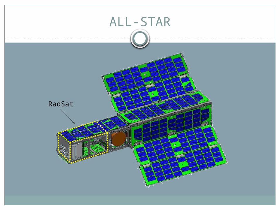
Functional Decomposition: Level 0
AntennaSignal
Processing
ALL-STAR

Functional Decomposition: Level 1
ANTENNA
Signal Processing
LNAMixe
rBPF
s
Detector Diode LPF ADC µC
Horn

Physical Design Constraints
The RadSat will be designed by implementing the 3U CubeSat specifications to be connected to the primary ALL-STAR system housing
The length of the RadSat must be 6.5’’ x 2.5’’ x 2.5’’
The volume of the RadSat must be 40.625 in3.Must not exceed 2000 gCenter of gravity must be located at the
center of the RadSat.

ALL-STAR System
ALL-STAR (Agile Low-Cost Laboratory for Space Technology Acceleration Research) Master power and communications delivery platform Compatible with all 3U CubeSat satellites (including RadSat)
ALL-STAR Capabilities Power distribution to payload (RadSat) A/D Converters GPS accuracy within 100 m Configuration memory 62.5 KB Data memory 3276.8 MB Attitude pointing accuracy: 1° Downlink rate: 250 kbps Uplink rate: 9.6 kbps

ALL-STAR System
Communication Handshaking from RadSat to the ALL-STAR bus Serial data will be exchanged using a pin-out
connector Bus capable of transmission rates of 20 mbps ALL-STAR bus protocol will be used
Error checking bits Continuation bit Frame number Frame length Frame data (Timestamp, Response, Type, Opcode,
Length, Message, Checksum)

ALL-STAR Power Constraints
ALL-STAR Electrical Power System (EPS) Delivers 4-5 W of power continuously Can deliver 25 W of power for 15 minutes of every
orbitVoltages available
Unregulated Battery 12V 3.3V

ALL-STAR Programming Concept
ALL-STAR features will be programmed in C to accept RadSat packets . Address memory management of raw data Program weighting functions, send temperature data
Interface between RadSat and MATLAB test surface via UART to be implemented. MATLAB and C will be used.
RadSat’s command and data handling procedures will be written in C and programmed on the Xmega microprocessor

Hardware Requirements
Trigger ADC to sample Upwards of 10 channels Simultaneous sampling 16-bit resolution (pin-compatible to 24-bit resolution)
Process data and pass samples to ALL-STARAcquire a data point at no slower than 2 Hz
to maintain spatial resolution Determined by orbital velocity and antenna -3dB angle
Interface with the ALL-STAR bus

Low Level Objectives
Raw digital data is collected from RadSat where no additional data processing will be done.
The raw data is sent to the ALL-STAR, and no additional data processing will be done.

Medium Level Objective
Raw digital data is collected from RadSat where no additional data processing will be made.
The raw data is sent to the ALL-STAR where it is stored and information can be processed to obtain temperature data to transfer to ground station.

High Objective
Raw digital data is collected from RadSat where data will be processed and sent to the ALL-STAR in real-time.
ALL-STAR receives already processed temperature data and stores in memory until downlink can be achieved

Division of Labor
Brian French Matlab test code programming RF test & assembly
Maxwell Perez Operating system Programming bus interface
Phillip Crosby Filtering RF assembly Documentation
David Harrison Filtering Sensors: Temperature, Attitude Power management
Daniel Gale Digital hardware PCB layouts firmware

Schedule

Milestone 1 Milestone 2
RF assembly completed and testing in progress
Digital board nearing completion
ALL-STAR interface completed and tested
Firmware completeFirst and Second PCB
layouts tested
Calibration systems development in progress
Third PCB layout and fabrication complete
Miniaturization and Power management underway for RF
Data acquisitioning and conditioning complete
Schedule

Budget
Provided for us by Space Grant and Dr. Gasiewski RadSat Will Provide
Components Quantity Price Total Cost
Microprocessor 6 13 78.00
Microprocessor dev environment 1 40 40.00
RF Diodes 20 15 300.00
ADC 5 12 60.00
Passives 30.00
PCBs 3 66 198.00
Wire and Connectors 50.00
RF Connectors 50.00
FTDI chips 6 12 72.00
Power regulators 6 5 30.00
Current sensors 6 1 6.00
Temperature sensor 6 1 6.00
MOSFETs 30 1 30.00
TOTAL = $950.00
Component
Price
Mixer $45,000
Filter $2000 x 10
$20,000
Amplifier $15,000
Horn $5,000
Misc. Parts $10,000
Total $95,000

Risks & Contingencies
High power drawSpatial constraints
exceeded FinanceInsufficient data
captureHigh frequency is
difficult to testDifficult to DemoLack of experience
with High Frequency RF
Table top model will have no power limit
Table top model will have no space limit
Space Grant and Dr. Gasiewski will provide financial backing
Increase data capture as much as possible
Use of test facilities at NIST and possible CU Labs

Questions?