Team 19 Project Proposal and Feasibility Study · Team 19 . Project Proposal and Feasibility Study...
75
Team 19 Project Proposal and Feasibility Study Mark De Haan Jeremy Kamp Nathan Laframboise Julie Swierenga Wendy Tabler Engineering 339/340: Senior Design Project Calvin College 8 December 2014
Transcript of Team 19 Project Proposal and Feasibility Study · Team 19 . Project Proposal and Feasibility Study...

Team 19 Project Proposal and Feasibility Study
Mark De Haan Jeremy Kamp
Nathan Laframboise Julie Swierenga Wendy Tabler
Engineering 339/340: Senior Design Project
Calvin College
8 December 2014

Copyright © 2014, Calvin College, Mark De Haan, Jeremy Kamp, Nathan Laframboise, Julie Swierenga, and Wendy Tabler

EXECUTIVE SUMMARY The ACE team will design a water distribution system for the city of Apatug, Ecuador, with assistance from Bruce Rydbeck, the project client. Currently, Apatug’s water is supplied by a 110 millimeter diameter polyvinyl chloride (PVC) feed line. This line runs 7 kilometers from protected springs at 4360 meters elevation to deliver water to the community at 3339 meters. The team’s water distribution system design will include disinfection of source water using a liquid hypochlorite dosing system with a nonelectric fluid-driven injector pump. Water will then be delivered and will deliver water to the 500 homes in the community using a pipe network with various sizes of PVC pipe. With an elevation difference of 190 meters from the highest to the lowest home, Apatug presents a challenge in delivering water to each home at pressures between 20 and 60 meters of pressure. The team plans to address this challenge using five storage reservoirs at tactically chosen locations to create pressure zones. These pressure zones will be used to control pressures for homes at different ranges of elevation. Elevation data was acquired through a survey performed by an Ecuadorian engineer Cesar Cortez. Using this survey data, the team was able to model the houses and elevations in EPANET. With EPANET, the team has modeled the entire pipe network complete with storage tanks and pressure reducing valves.
In January, the team will travel to Apatug to meet with the community, collect survey data, visit neighboring distribution systems, and perform chemical analysis and water quality testing. The trip will inform future design decisions, including the final layout of the distribution system and the design of the chlorine dosing system. A bench scale study will also be implemented following the trip to investigate the effectiveness of selected injector pumps. This Project Proposal and Feasibility Study investigates design alternatives, design norms, project criteria, and project goals, providing a preliminary distribution design and an affirmation of the feasibility of the project.

i
Table of Contents Table of Contents ........................................................................................................................................... i
Table of Figures ........................................................................................................................................... iv
Table of Tables ............................................................................................................................................ iv
1. INTRODUCTION .................................................................................................................................... 1
1.1 Senior Design Background ................................................................................................................. 1
1.1.1 Calvin Engineering Program ........................................................................................................ 1
1.1.2 Senior Design Class ..................................................................................................................... 1
1.1.3 Team Members ............................................................................................................................ 1
1.2 Project Background ............................................................................................................................. 3
1.2.1 Project Summary .......................................................................................................................... 3
1.2.2 Location: Apatug, Ecuador .......................................................................................................... 3
1.2.3 Current Water Situation ............................................................................................................... 5
1.2.4 The Client ..................................................................................................................................... 8
1.2.5 The Project ................................................................................................................................... 8
2. PROJECT MANAGEMENT .................................................................................................................... 9
2.1 Team Organization .............................................................................................................................. 9
2.2 Schedule .............................................................................................................................................. 9
2.3 Budget ................................................................................................................................................. 9
2.4 Method of Approach ......................................................................................................................... 10
3. PROJECT OVERVIEW ......................................................................................................................... 11
3.1 Purpose and Objectives ..................................................................................................................... 11
3.1.1 Distribution ................................................................................................................................ 11
3.1.2 Chlorination ............................................................................................................................... 11
3.2 Design Constraints ............................................................................................................................ 12
3.3 Design Criteria .................................................................................................................................. 12
3.3.1 Disinfection Method .................................................................................................................. 12
3.3.2 Disinfection Dosing ................................................................................................................... 13
3.4 Design Norms ................................................................................................................................... 13
3.4.1 Cultural Appropriateness ........................................................................................................... 13
3.4.2 Transparency .............................................................................................................................. 13
3.4.3 Justice ......................................................................................................................................... 14

ii
3.5 Design Alternatives ........................................................................................................................... 14
3.5.1 Distribution Pressure Control ..................................................................................................... 14
3.5.2 Distribution Pressure Zones ....................................................................................................... 14
3.5.3 Distribution Design Approach ................................................................................................... 17
3.5.4 Form of Chlorine Disinfection ................................................................................................... 17
3.5.5 Chlorine Dosing System ............................................................................................................ 18
4. INITIAL RESEARCH ............................................................................................................................ 19
4.1 Distribution System .......................................................................................................................... 19
4.1.1 Importance of Community Ownership....................................................................................... 19
4.1.2 Typical Costs by Usage.............................................................................................................. 20
4.1.3 Standard Design Values ............................................................................................................. 22
4.1.4 Household Connections ............................................................................................................. 22
4.2 Disinfection ....................................................................................................................................... 23
4.2.1 Republic of Ecuador Disinfection Policy ................................................................................... 24
4.2.2 Chlorine Alternatives ................................................................................................................. 24
4.2.3 Dosing Alternatives.................................................................................................................... 26
4.3 Available Materials ........................................................................................................................... 27
4.4 Water Reservoir Design .................................................................................................................... 27
5. WATER SYSTEM MODEL DEVELOPMENT .................................................................................... 29
5.1 Software ............................................................................................................................................ 29
5.1.1 EPANET .................................................................................................................................... 29
5.1.2 Civil 3D to EPANET ................................................................................................................. 29
5.2 Materials and Properties ................................................................................................................... 29
5.3 Design Values ................................................................................................................................... 29
5.4 Design Approach .............................................................................................................................. 30
5.5 Future Design Testing ....................................................................................................................... 33
5.5.1 Current Design ........................................................................................................................... 33
5.5.2 Possible Changes to Design ....................................................................................................... 33
6. CHLORINATION BENCH STUDY...................................................................................................... 35
7. TRIP TO ECUADOR ............................................................................................................................. 36
7.1 Trip Goals ......................................................................................................................................... 36
7.2 Tentative Itinerary ............................................................................................................................. 36
7.3 Water Testing Plan ............................................................................................................................ 37

iii
7.3.1 Purpose ....................................................................................................................................... 37
7.3.2 Objectives .................................................................................................................................. 37
7.3.3 Key Parameters .......................................................................................................................... 37
7.3.4 Field Test Plan ........................................................................................................................... 39
8. PROJECT FEASIBILITY CONCLUSION ............................................................................................ 41
8.1 Cost Analysis .................................................................................................................................... 41
8.1.1 Distribution System Cost ........................................................................................................... 41
8.1.2 Chlorination Dosing System Cost .............................................................................................. 41
8.2 Sustainability Study .......................................................................................................................... 42
8.3 Distribution System Design .............................................................................................................. 43
8.4 Proposed Chlorination System .......................................................................................................... 44
9. BASIS OF DESIGN ............................................................................................................................... 46
9.1 Distribution System Design .............................................................................................................. 46
9.2 Chlorination System Design ............................................................................................................. 47
9.3 Chlorination Bench Scale Study ....................................................................................................... 47
9.4 Future Work ...................................................................................................................................... 47
10. AKNOWLEDGEMENTS ..................................................................................................................... 48
11. REFERENCES ..................................................................................................................................... 49
Appendix A – Gantt Chart ............................................................................................................................ 1
Appendix B – Disinfection Decision Matrices ............................................................................................. 1
Appendix C – Pressure Zone and Tank Mathcad and Excel Calculations .................................................... 1
Appendix D – Injector Pump Specifications for MixRite and Dosmatic® ................................................... 1
Appendix E – Distribution System Schematic .............................................................................................. 1
Appendix F – Chlorine Dosing Station Schematic ....................................................................................... 1
Appendix G – Chlorine Dosing Mathcad Calculations................................................................................. 1

iv
Table of Figures Figure 1. The ACE Team: Jeremy Kamp, Mark De Haan, Nathan Laframboise, Julie Swierenga, and
Wendy Tabler (Photo courtesy of John Sherwood) ...................................................................................... 2
Figure 2. Location of Apatug, Ecuador, Indicated by the Red Placemark .................................................... 4
Figure 3. Terrain Map of Apatug, Ecuador ................................................................................................... 5
Figure 4. Protected Spring Collector Details, Plan View [50] ...................................................................... 6
Figure 5. Protected Spring Collector Details, Section View [50] ................................................................. 7
Figure 6. Piezometric Head Diagram in a Hydraulic System (sketch by Julie Swierenga). ....................... 15
Figure 7. Five Pressure Zone System.......................................................................................................... 16
Figure 8. Percent of rural population with access to improved water source in Ecuador, United States [11]
.................................................................................................................................................................... 19
Figure 9. Picture of a Typical Spigot [2] .................................................................................................... 23
Figure 10. Schematic of Chlorine Electrolysis to Produce Chlorine Gas. [30] .......................................... 25
Figure 11. Pressures in system under average day flows ............................................................................ 31
Figure 12. Pressures in system under 20-year peak hour flows .................................................................. 32
Figure 13. Representation of Pressure Variation due to Different HGL's .................................................. 34
Figure 14. Bench Scale Design ................................................................................................................... 35
Figure 15. Schematic of a Secchi Disk as a Turbidity Measurement [46] .................................................. 38
Figure 16. Process Flow Diagram for Chlorine Dosing. ............................................................................. 44
Figure 17. EPANET Model of Apatug with Elevations ............................................................................. 46
Table of Tables Table 1. Church's Method typically used for design of rural water systems in Ecuador [10] .................... 17
Table 2. Typical values for marginal costs of water supply [16] ................................................................ 21
Table 3. Water Testing Equipment and Cost Estimates. ............................................................................. 40
Table 4. Preliminary Pipe Lengths Estimate ............................................................................................... 41
Table 5. Unit Cost of Similar Projects [49] ................................................................................................ 41
Table 6. Preliminary Dosing System Cost Estimate ................................................................................... 42
Table 7. Summary of Distribution System Components ............................................................................ 47

1
1. INTRODUCTION
1.1 Senior Design Background
1.1.1 Calvin Engineering Program
The Calvin Engineering Program is a program that has been accredited by the Accreditation Board of
Engineering and Technology (ABET). The Calvin Engineering Program seeks to shape engineering
students to apply their Christian faith to future practice while using their liberal arts background to
become well-rounded professionals. The Calvin Engineering Program also aids students in finding
summer internships and provides opportunities for students to study abroad in such locations as Germany,
the Netherlands, Kenya, China, and Cambodia. Through all these opportunities, the Calvin Engineering
Program works toward its mission statement: to “equip students to glorify God by meeting the needs of
the world with responsible and caring engineering.” [1]
1.1.2 Senior Design Class
This design project is a major component of the Calvin Engineering Department’s capstone class, Senior
Design, which is comprised of two classes: ENGR 339 in the fall and ENGR 340 in the spring. The
classes combined total 6 credit hours and are a combination of in-class lectures as well as designated
project work hours. The goal of the fall semester is project development and feasibility, and the spring
focuses on project implementation. Calvin’s Senior Design class empowers engineering students to
integrate design norms and a Christian worldview into their projects while implementing the technical
skills they have learned in their past four years of college. This experience then prepares the students for
thoughtful and significant future careers.
1.1.3 Team Members
The members of Team 19, pictured in Figure 1, are all seniors majoring in engineering at Calvin College
in the civil/environmental concentration. Each member of the team has unique interests, skill sets, and
experiences to bring to the project, and several of the team members have participated in international
projects related to water distribution. All of the team members have a passion for water resources and
hydraulic engineering, and they are committed to using their skills and education to work with the
community of Apatug to design a sustainable water distribution system that delivers clean water to the
members of the village.

2
Figure 1. The ACE Team: Jeremy Kamp, Mark De Haan, Nathan Laframboise, Julie Swierenga, and Wendy Tabler
(Photo courtesy of John Sherwood)
Mark De Haan
Mark De Haan is from Zeeland, Michigan (Feel the Zeel!). Mark is particularly interested in the water
resources aspect of the civil concentration. In his free time, Mark works for the Sports Information
Department at Calvin and enjoys writing game recaps and broadcasting for a wide variety of sports. Mark
also enjoys watching professional sports, and unfortunately, he grew up as a Detroit Lions fan. Upon
graduation, Mark intends to pursue a job in West Michigan.
Jeremy Kamp
Jeremy Kamp is from Orland Park, Illinois. He has many interests in the field, including hydrology, water
resources, site development, and construction management. When he isn’t hitting the books hard, Jeremy
enjoys playing baseball for Calvin College. Besides his interest in sports, Jeremy loves spending time in
the outdoors fishing and hunting. Since Jeremy has enjoyed his four years at Calvin so much, he plans to
pursue a job in West Michigan upon graduation in May 2015.
Nathan Laframboise
Nathan Laframboise is from Bolingbrook, Illinois. His areas of interest lie in water treatment processes
and water distribution. Ultimately, he wishes to see all people have access to clean, potable water in such
a way that does not over-burden the environment. After graduation Nathan would like to work as a city
civil engineer or for a county drain commission. In his free time Nathan enjoys studying theology, going
to family sporting events, and developing clever puns to the chagrin of his teammates.

3
Julie Swierenga
Julie Swierenga is from Greensboro, North Carolina. Through research, studying abroad, and an
internship, she has had many opportunities to work with water resources, distribution, and treatment. The
intersection between civil engineering and geography is particularly interesting to Julie, including the way
that humans interact with space. Julie plans to pursue a job in water resources engineering upon
graduation.
Wendy Tabler
Wendy Tabler is from Milwaukee, Wisconsin. Her decision to move away for college has taken her much
farther than just Grand Rapids; with Calvin, Wendy has traveled to the Netherlands, to Kenya, to Peru,
and now to Ecuador. Wendy is passionate about international engineering, and is especially interested in
the connection between structures and water. After graduating from Calvin, Wendy plans to attend
graduate school to continue her education in structural engineering.
1.2 Project Background
1.2.1 Project Summary
Team 19, which has named itself the ACE (Agua y Cloración en Ecuador) Team, is designing a water
distribution system complete with chlorination dosing for the village of Apatug, Ecuador.
1.2.2 Location: Apatug, Ecuador
Apatug is a village of approximately 500 homes located in rural Ecuador, as shown in Figure 2 and Figure
3. The village’s current water source is a protected mountain spring shared with the surrounding
communities. A water distribution system is needed to provide clean water to each home. Because of its
location in the Andes Mountains, the difference in elevation between the source spring and the homes in
Apatug is significant. To maintain appropriate water pressures throughout the system, either the creation
of different pressure zones or the extensive use of pressure-reducing valves (PRVs) will be required.

4
Figure 2. Location of Apatug, Ecuador, Indicated by the Red Placemark

5
Figure 3. Terrain Map of Apatug, Ecuador
1.2.3 Current Water Situation
Apatug currently gets its water from a protected spring which is shared with four other communities,
serving a total of 1700 homes. A 110 millimeter diameter PVC feed line runs 7 kilometers from the
springs at 4360 meters elevation to deliver water to the communities, producing a total volumetric flow of
28 liters/second (L/s). [2] The spring protection and the feed line from the springs to the community were
completed in 2014, but the community currently has no water treatment or distribution network. [3]
In Apatug and in the case of most rural Ecuadorian villages, water is gathered from mountain springs and
piped to the village. This water is typically very clean, and can be drunk directly from the source without
treatment. While the water is clean, constant quality must be insured. This insurance takes the form of
spring protection. In order to keep animals out of the springs, the springs are covered with concrete or
steel structures which keep animals, both wild and domestic, and contaminated surface water from
tainting the spring water, as pictured in Figures 4 and 5.

6
Fig
ure
4.
Pro
tect
ed S
pri
ng
Coll
ecto
r D
etail
s, P
lan
Vie
w [
50
]

7
Fig
ure
5.
Pro
tect
ed S
pri
ng
Coll
ecto
r D
etail
s, S
ecti
on
Vie
w [
50
]

8
Spring protection structures must also protect the spring from water runoff due to large storms. For this
reason, Bruce Rydbeck states in a paper that “it is important that springs be excavated to a sufficient
depth so that the water is collected from the pervious gravel, sand, or fissured rock where water is flowing
before coming into contact with the topsoil.” By protecting springs, rural communities are provided with
a source of water which has constant quality, often mitigating the need for treatment and keeping
disinfection simple.
The community of Apatug has been visited by a global Christian health organization called MAP
International for over four years, receiving health and hygiene training. MAP has done a preliminary
study of water distribution changes, but it did not include a topographic study of the feed line and
required the uncommon construction of pressure breaking tank in mountainous areas. MAP asked Reach
Beyond (formerly HCJB Global) to do a water study of the community in 2011, and Reach Beyond
produced a design report including spring protection measures and construction of the feed line. [2]
The Ecuadorian government has recently required that all municipal water distribution systems include
chlorination for disinfection. There has been cultural and social resistance to chlorinating water because
the process has largely been unregulated, leading to sporadic dosing and taste issues. Part of the design
project will include a design for a chlorine dosing system that provides a consistent concentration of
chlorine in the distribution system, eliminating harmful pathogens while minimizing taste issues.
1.2.4 The Client
The project for the community of Apatug was proposed to the team by Bruce Rydbeck, PE, D. WRE., a
resident of Quito, Ecuador, and Rural Water Supply Consultant for Life Giving Water International. Mr.
Rydbeck has worked with many communities throughout Ecuador and Peru, coordinating with local
engineers and community members to perform spring protection, implement water distribution systems,
and investigate chlorine dosing in rural Ecuador. In June of 2014, team members Julie Swierenga and
Wendy Tabler traveled to Peru with a team of engineering students and professors to work with Mr.
Rydbeck to analyze and recommend changes to a rural water distribution system. This relationship led to
this senior design project.
1.2.5 The Project
The ACE Team will work in conjunction with Mr. Rydbeck and Ecuadorian engineer, Cesar Cortez, to
design a water distribution system for the community of Apatug. The system will be designed to utilize
locally available materials and installation methods, ensuring that pressures are well-regulated throughout
the village. In addition, a chlorine dosing system will be designed as part of the water system. The dosing
system will also focus on culturally appropriate technologies and locally-accessible materials and
chemicals to provide consistent disinfection throughout the water distribution network.

9
2. PROJECT MANAGEMENT
2.1 Team Organization The ACE Team has assigned team roles to facilitate project management and implementation. However,
individual team members are responsible for research activities, as well as tracking hours. All of the team
members also contribute to report writing.
Wendy Tabler is responsible for scheduling and team management, ensuring that all tasks are completed
in a timely manner. She has also taken a supportive role in developing the computer model for the water
distribution system. Jeremy Kamp’s primary role is leading the computer model development for the
water distribution system. Jeremy is also responsible for contributing to the business plan and cost
estimation components of the project. Mark De Haan is in charge of the budget for the team. He is also
responsible for the completion of the business plan and contributing to chlorine bench study development.
Nathan Laframboise is responsible for organizing the research efforts of the team. He has taken a lead in
communicating with pump suppliers for bench study materials and contributing to chlorine bench study
development. Julie Swierenga is in charge of the website for the team, as well as email communications
with the client, Bruce Rydbeck. She is also responsible for chlorine dosing calculations and design
considerations.
2.2 Schedule The two semesters of the senior design course have been split into two main focuses for the ACE Team.
The first semester will be spent mainly on designing the water distribution system while also looking at
the feasibility of the project. The second semester will focus on the design of the chlorination system and
the method through which the chlorine will be administered to the distribution system. In January, four
members of the ACE Team will travel to Ecuador to visit the community, perform water chemical
analysis and quality testing in Apatug, and visit similar distribution systems that are currently in
operation. The complete schedule is outlined in a Gantt chart, which is included in Appendix A.
On a weekly basis, the ACE Team gathers to share research and modeling results and also has a meeting
with their project advisor each Monday at 1:30 pm to discuss progress and address questions. After this
meeting, the team decides on a plan of action for the next week and tasks each member should
accomplish. Each team member tracks hours spent on the project using a spreadsheet located on a shared
Google Drive. Since the project has two major components: the water distribution system and the chlorine
dosing system, team members meet in smaller groups more frequently throughout the week.
2.3 Budget The ACE Team has been provided with a budget of around $500. This majority of this money will go
toward the bench scale study, purchasing a flow injector pump to administer chlorine to a stream of water
which varies in flow. This pump will cost approximately $300. Four members of the ACE Team also plan
on traveling to Ecuador at the end of January to connect with members of the community and to receive
input regarding the best locations in the village for reservoirs and piping. Between flights, living
accommodations, and a water testing kit necessary to collect water quality data, the trip has been
estimated to cost $5319 in total. Mark De Haan has been placed in charge of ACE Team’s budget.

10
When making design decisions about materials and methods to use in the distribution and chlorination
system in Apatug, the ACE Team does not simply consider options of lowest cost to make design
decisions. Cultural appropriateness is a key aspect of selecting construction and chlorination materials. In
addition, the community of Apatug will likely seek government assistance for assuaging the costs of the
recommended distribution system. The ACE Team will use the provided senior design for bench study
materials and water testing material necessary for chlorine dosing design, but trip funding will be funded
by team members, and the distribution system itself will be funded by the community and Ecuadorian
government.
2.4 Method of Approach The ACE Team has approached this senior design project with humility, gratitude, and awareness of the
profound effect that the project may have on the people of the Apatug community.
First, the team is aware that the assistance of more experienced and knowledgeable mentors is essential to
the success of the project. The team has used the resources of professors, an industrial consultant, and the
project client to ask questions and seek information. A humble posture allows the team to be open to
suggestions and new alternatives that have not yet been considered. Humility puts the team in a position
of learning, facilitating communication between team members and mentors, and also creating an
incentive for continued research and learning throughout the project.
Secondly, the team is grateful for the opportunity to partner with Bruce Rydbeck and the community of
Apatug to utilize time and resources to design a distribution and chlorination system for the community.
The team has been blessed with access to higher education, engineering software, technical knowledge,
and a supportive learning environment, which are all resources that can be used to benefit the people of
Apatug. The team is also grateful for the opportunity to be hosted by the community in January.
Finally, the ACE Team is aware of the gravity of delivering clean water to a community, which provides
inspiration and incentive for work on all aspects of the project. All professional engineers design and
implement projects that have an effect on human health or well-being, and this project has the potential to
provide clean water to the residents of Apatug for years to come. This knowledge reinforces the
importance of design norms in the implementation of the project, particularly those of justice, cultural
appropriateness, and sustainability.
This project is being approached with a methodology of research, model development, testing, and
redesign. After initial research was performed, a computer model was developed to model the distribution
system. This model will be tested using EPANET software and will also be informed by communication
with the community of Apatug before a final recommendation is made. Similarly, the chlorination system
has a foundation of research, and a bench scale study is planned to test the effectiveness of the chosen
system. It is important that each aspect of the design be tested and evaluated before a final design is
recommended.

11
3. PROJECT OVERVIEW
3.1 Purpose and Objectives
3.1.1 Distribution
The purpose of designing a water disinfection and distribution system for Apatug, Ecuador, is to supply
its 500 households with clean water under manageable pressures. Currently, small reservoirs scattered
throughout the village are shared by animals and villagers. By providing a metered tap connection in
most homes, the villagers will no longer have to walk to get water that has been contaminated by animals.
In November 2002, the United Nations Committee on Economic, Social and Cultural Rights adopted
General Comment No. 15, which declares that “the human right to water is indispensable for leading a
life in human dignity [and] is a prerequisite for the realization of other human rights.” [4] This right is
further defined as “entitling everyone to sufficient, safe, acceptable, physically accessible and affordable
water for personal and domestic uses.” [4] In July 2010, the United Nations (UN) General Assembly
explicitly recognized this right through Resolution 64/292. [5] The UN Millennium Development Goals
call for cutting the “proportion of the population without sustainable access to safe drinking water and
basic sanitation” in half by 2015. [6] This distribution system works toward this Development Goal and
will provide the villagers of Apatug to their human right of sustainable access to clean drinking water.
In designing the system, the ACE Team was given certain objectives by the client, Bruce Rydbeck. [3]
The reservoirs should be designed to hold 35% to 40% of the average daily demand for a given pressure
zone or zone of service. Static pressure at each home should be in the range of 20 to 60 meters, or if need
be 10 to 70 meters, which would be admissible because Apatug is a mountainous community. Servicing
as many houses as possible with a private tap is a main objective. In the cases where a home connection
is not feasible, a community faucet will be constructed nearby. The main objective for the distribution
system is to provide a full design report that can be submitted to community leaders, allowing Apatug to
begin construction of the reservoirs and pipelines for the distribution system.
3.1.2 Chlorination
The purpose of chlorination is to kill pathogens that can grow on the inside of pipes, walls of storage
tanks, and water mains. Disinfection renders the water safe for human consumption. Currently, water is
collected from a protected spring on Mt. Carihuairazo and transported to the city of Apatug, Ecuador, via
a seven kilometer PVC water main. Although the spring water is of acceptable quality due to natural
filtration, there is still ample opportunity for organisms to grow within the distribution system.
Additionally, in 2008, Ecuador passed legislation making it mandatory that all cities have chlorine
residual in their systems to ensure against pathogen growth. [7] Apatug is a large enough community that
a chlorine residual in the water system is necessary if any further development funding by the Ecuadorian
government is to be supplied.
The disinfection objective of this project is to administer chlorine to the distribution system according to
Ecuadorian regulations. Further specifications have been set forward by our client Bruce Rydbeck. [8]
Chlorine should be introduced into the system using liquid injection pumps. These pumps should be
adjustable so they increase their chlorine output during times of high demand and dial back during times
of low demand. The range of flow rates the pumps will be expected to operate at vary between 1 to 6 L/s,
and the pumps should dose to range of 0.5 to 2 parts per million (ppm). It is ideal to use chlorine that can

12
be acquiesced within Ecuador. Given the low flow rates at certain nodes it is critical that a chlorine
residual be maintained to prevent pathogenic growth.
3.2 Design Constraints There are a number of aspects of the design process that will constrain how the final product is developed.
The first constraint is the disinfection regulations which have been set by the Ecuadorian government that
state that chlorine must be used for disinfection. While chlorine is normally used as the primary
disinfectant in the majority of water systems, this regulation prevents the use of more complex
disinfection methods such as ozone or ultraviolet, which do not leave a residual disinfectant in the
distribution system.
Material availability in Ecuador also limits the design of the Apatug distribution system. To design a
system which is culturally appropriate, materials such as ductile iron are quickly ruled out of the design
process due to their lack of availability. Additionally, in order to be culturally appropriate, material cost
must be considered. Instead of designing the system as a looping network, which would provide constant
water supply even during pipe replacement, designing the system as a branching network requires much
less material and makes finding leaks significantly easier; therefore, it is a more desirable design strategy.
Another important constraint in designing the distribution system is the change in elevation. These
elevation differences require the placement of reservoirs setting a pressure zone or PRVs to keep
pressures from being too high in various parts of the village. This large elevation range constrains how
much of the village can be regulated by a single pressure district and dictates the number of pressure
districts that are necessary. The village consists of 500 homes, and all of these homes must be served by
the 5 L/s flowing from the spring while maintaining adequate pressures.
Along with the establishment of pressure districts, the design specifications of the system are based on per
capita daily consumption of water and the number of residents within a given pressure district. Water
demand constraints will not only play a role in the sizing of the pipes but also in the sizing of the
reservoirs.
All of these factors must be taken into careful consideration when designing the distribution system.
Inability or unwillingness to do so could result in a faulty product or system which finds itself in
disrepair.
3.3 Design Criteria In order to design a chlorine dosing system, design decision must be made that fulfill the goal of the
project while considering the design norms of cultural appropriateness, justice, and sustainability. These
design criteria are also informed by the characteristics of different chlorination methods. Decision
matrices were developed and used to determine the most appropriate disinfection material and delivery
method for the community of Apatug.
3.3.1 Disinfection Method
The following criteria are considered in determining the disinfection methods and are used to weigh
alternatives as shown in a Decision Matrix found in Appendix B:

13
1. Chemical Source – Does the chemical arrive ready to use or does it need further refining before it
can be dosed?
2. Contact Time – How much time is needed to get the desired kill of organisms? This number is
based upon ideal conditions of pH = 8, 75oF water with no turbidity or NOM.
3. Typical Application Dose – How much disinfectant needs to be added per liter of water (mg/L)?
4. Safety – How hazardous is the chemical to humans and does anyone handling the chemical need
to wear special clothing to mitigate exposure?
5. Ease of Use – Can the disinfectant be used as both a primary and secondary disinfectant?
6. By-Products – If the disinfectant does come into contact with natural organic matter (NOM), are
disinfection by-products (DBPs) at threat of formation in the system?
7. Legality – Will the disinfectant leave a chlorine residual in the system in accordance with
Ecuadorian regulation?
3.3.2 Disinfection Dosing
The following criteria are considered in determining the disinfection dosing methods and are used to
weigh alternatives as shown in a second Decision Matrix found in Appendix B:
1. Liquid Inject – Can the chlorinator handle liquid sodium hypochlorite?
2. Adjustable Feed Rate – Is the feed rate self-regulating?
3. Dependability – Is the method rugged enough for prolonged use without maintenance?
4. Ease of Construction – Are special expertise needed to set the system up properly?
3.4 Design Norms Design norms provide a framework through which the project will be completed. These design norms
ensure that the project is done with the correct mindset and that the ethical guidelines, which are an
important aspect of the engineering profession, are considered in the areas of technical design and ethical
constraints.
3.4.1 Cultural Appropriateness
When working on a project in a foreign country, designing with cultural appropriateness in mind is
paramount. In a village that has never had a water distribution system with disinfection, it is important
that the community embraces the project so the system does not fall into disrepair or cease to provide the
required disinfection. For these reasons, designing the system to be cost effective and easy to build by
local labor is important, while implementing a design using materials that are readily available is equally
important in the situation that maintenance or repair is necessary. Additionally, the chlorination must be
carefully regulated so that it has a minimum effect on taste. Cultural appropriateness also takes into
account non-technical aspects of the design. The potential tank locations may be limited by current
conceptions of different places in the Apatug area, desired spigot locations may be defined by current
practices, and network connections may need to be defined by cultural relationships. In order for the
system to be embraced, it must work in conjunction with the culture of Apatug.
3.4.2 Transparency
In order to design a system which will work correctly and be reliable for years to come, transparency is
important for all aspects of the design process. The team has to be upfront with the client, advisor, and
industrial consultant so that any problems the team may face will be solved correctly and efficiently. Any

14
questions should be communicated clearly to ensure understanding between team and consultant. Any
potential cultural issues must be addressed with the community. While learning is an important aspect of
the senior design course, the team is asked to produce a final product, which should be designed to be
efficient and reliable. For this reason, communication between the team and its consultants must be
transparent, so all aspects of the project are correctly addressed.
3.4.3 Justice
The right to clean, drinkable water often requires hard work on the part of those living in developing
countries like Ecuador. For this reason, justice is the final design norm around which the team will focus
the project. The design and implementation of a water distribution system complete with disinfection
allows the people of the village of Apatug to have access to an ample supply of clean water. Through that
access, the team seeks to bring justice to those who are so often stuck on the margins of society.
3.5 Design Alternatives
3.5.1 Distribution Pressure Control
In order to keep pressures at the household connections between 20 and 60 meters (or 10 to 70, if
necessary), two alternatives are possible. Firstly, PRVs could be used at each residence to lower the high
pressures caused by the significant elevation difference to manageable target pressures. Although these
would be simple to install with the new system, they do not lower pressures within the pipes themselves
and more valves would be required with the addition of new houses and future population growth.
According to a survey performed by Cesar Cortez, the lowest reservoir on the pipeline before reaching the
town is at an elevation of about 3490 meters, which is about 200 meters above the lowest elevation
household in Apatug. This elevation drop would cause very high pressures within the pipes and put the
system at risk of collapsing. Alternatively, pressure head zones could be created by constructing
reservoirs at different elevations throughout the distribution system. Reservoirs provide stability to the
entire system, protecting both the homes and pipes from excessive high pressures and breaking the
pressure of the incoming water. Reservoirs also equalize flow, allowing the system to better deliver peak
flows, and they provide storage for an emergency water supply. Although reservoirs are more costly to
install, the client, Bruce Rydbeck, has requested the use of reservoirs because Apatug is a compact
community and the reservoirs provide significant long term advantages. [9]
3.5.2 Distribution Pressure Zones
The hydraulic pressure in a system is governed by the equation:
𝐻 = 𝑧 +𝑃
𝛾 , (Equation 1)
where 𝐻 is the piezometric head, 𝑧 is the elevation, 𝑃 is the pressure, and 𝛾 is the unit weight of water.
With pressures given in units of head (such as meters), this equation simplifies to
𝐻 = 𝑧 + 𝑃. (Equation 2)
As illustrated by Figure 6, the piezometric head is set by the elevation of the water level in the tank
connected to that branch of the system. The head levels needed in the system can be set by the desired
range of experienced pressures at the elevations of the houses. Because the pressure is greatest where
elevation difference is greatest, the highest pressure in the range can be determined by using the elevation

15
for the lowest house in Apatug. This assumption sets the head in the first pressure zone. From there, the
highest elevation of a house that can be served within the acceptable range of pressures for this calculated
head can be determined. One meter was added to this value to determine the lowest possible elevation for
the second pressure zone. This process was repeated until all houses were contained within a pressure
zone. Calculations can be found in Appendix C.
Figure 6. Piezometric Head Diagram in a Hydraulic System (sketch by Julie Swierenga).
Following these calculations, Apatug’s distribution system could be designed as a four pressure zone
system, requiring 18 PRVs for the outlying households, or as a five pressure zone system with room for
growth. The five pressure zone system can be seen in Figure 7. Because the use of PRVs was discouraged
by our client and the client suggested using either four or five zones to provide for future growth, the
recommended design will use five zones established by five reservoirs.

16
Figure 7. Five Pressure Zone System

17
3.5.3 Distribution Design Approach
Rural water distribution system pipe sizes are normally based on Church’s method, which identifies the
size of pipe needed by the area and number of connections that pipe serves in a table, as given in Table 1.
Table 1. Church's Method typically used for design of rural water systems in Ecuador [10]
PVC Pipe
Diameter
Interior Pipe
Diameter [mm] Area [mm2]
Number of Maximum
Connections
25 22.4 394.08 3
32 29.0 660.52 10
40 36.2 1029.22 20
50 45.2 1604.60 32
63 57.0 2551.76 50
75 69.2 3761.00 100
90 81.4 5204.03 125
The use of such a table allows field staff to make adjustments in the field as they see fit. This works
especially well, given that distribution systems are typically designed as branching systems for ease of
finding leaks and piping cost reduction. However, because Apatug is a compact area, it may lend itself to
some interconnected pipes. Loop-type systems are most easily analyzed with computer software.
Computer software also offers a lot of flexibility to test different possible scenarios and see the effect of a
small change to the entire system. Additionally, a commonly used program in industry called EPANET is
free for download from the Environmental Protection Agency (EPA). Field staff, as well as engineers like
Bruce Rydbeck and Cesar Cortez, could continue the use of this computer model without incurring
software charges. For its flexibility and graphical ability, the design will employ a computer model to test
the proposed distribution network. This will be checked with Church’s method to ensure results are
similar in order that field staff and local engineers will trust the design.
3.5.4 Form of Chlorine Disinfection
Disinfection of drinking water can be achieved through several different chemical processes, including
ultraviolet radiation (UV), oxidation, and chlorination. Because chlorine is the only one of these
disinfection processes that leaves a residual concentration in the distribution system after initial
chlorination, the Ecuadorian government requires the use of chlorine for disinfection.
There are several different chemical forms of chlorine that were evaluated by the team through initial
research and consideration of design considerations including cultural appropriateness, safety, and
humility. The alternatives considered were solid and liquid hypochlorite, chlorine dioxide, gaseous
chlorine, and chloramines. Chloramines were ruled out because of their limitation as a poor primary
disinfectant, and chlorine dioxide utilizes oxidation to disinfect rather than free chlorine. Gaseous
chlorine is the most efficient method for chlorine disinfection, but it is also the most difficult to transport
and store, and it is a deadly toxin requiring careful handling and management. A decision matrix was used
to select liquid sodium hypochlorite as the preferred method of disinfection due to its wide availability
and ease of storage and delivery. These chlorine alternatives are further investigated in the initial research
section of the report.

18
3.5.5 Chlorine Dosing System
After selecting liquid sodium hypochlorite as the disinfection method for Apatug, a dosing method for the
chlorination system must be selected. The main goal of the chlorine dosing system is to provide a
constant chlorine residual concentration that responds to daily fluctuations in water demand in the
community. Since chlorine has been largely unregulated in Ecuador, there is a mistrust of chlorination
disinfection due to taste issues that occur with inconsistent or overdosing. Therefore, the team
investigated several different types of dosing systems in an effort to maintain constant residual
concentrations that respond to demand variation, including timer-driven pumps, volumetric flow meters,
and nonelectric fluid-driven pumps.
Timer-driven pumps do not respond immediately to unexpected changes in flow, relying on consistent
demand patterns to maintain a constant residual chlorine concentration. Volumetric flow meters
connected to a dosing pump would allow for instant dosing response; however, flow meters require
electronic communication between the meter and the pump, increasing the complexity and potential for
failure of the dosing system. To best align with the design norms of cultural appropriateness and justice,
the team plans to implement a bench scale study to test the effectiveness of different brands of nonelectric
fluid-driven pumps, which deliver a chemical dose proportional to the flow of untreated water. These
nonelectric injector pumps are beneficial in that they are unaffected by occasional power outages, and
they minimize taste and odor issues associated with unregulated chlorination.

19
4. INITIAL RESEARCH
4.1 Distribution System Although rural communities in Ecuador are experiencing growth in their access to an improved water
source, it is still inadequate and in need of improvement. As seen in Figure 8, about 25% of rural Ecuador
still does not have access to an improved source. Although the gap between the rural water access in the
United States and Ecuador is closing, improvements in the area of water distribution and utility
infrastructure in villages such as Apatug are still needed.
Figure 8. Percent of rural population with access to improved water source in Ecuador, United States [11]
4.1.1 Importance of Community Ownership
The United States National Research Council found that “without adequate management and revenues,
small communities will be unable to maintain even low-cost technologies.” [12] If the community is not
involved with the design and implementation of the distribution system and does not take ownership of
the system, it is doomed to fail. Even if the team could design a system to address every necessity of the
village, if the community does not hold stakes in the system, any minor maintenance issue could cause the
collapse of the whole system. CEO Edward Breslin of Water For People notes that “approximately 50,000
rural water points are broken and US$215-360 million of investment wasted because of poor
programming and careless implementation.” [13] In order to facilitate this connection with the
community, the team’s travel to Ecuador will be key. There the team will be able to meet with community
leaders to determine where reservoirs can and should be located in order to finalize the distribution
network design.
In his article addressing water and sanitation strategy for developing countries, Daniel Okun, a professor
at the University of North Carolina, found that the second biggest problem facing water systems in the
0
10
20
30
40
50
60
70
80
90
100
1990 1994 1998 2002 2006 2010
Imp
rove
d w
ate
r so
urc
e, r
ura
l (%
of
rura
l po
pu
lati
on
wit
h a
cce
ss)
United States
Ecuador

20
developing world is insufficient water management, only second to the issue of inadequate systems that
cannot handle urban growth or apply inappropriate technology. [14] At the “Cusco+ 10” International
Seminar in 2010, this problem was still identified as one of the five challenges facing rural water
distribution systems in the next decade. [15] If a community is supplied with a solar panel to power an
aspect of the water system, but no one has training on how to protect or fix the technology, a broken
system means not only that the community’s system cannot be used but also that they have already been
“checked off” a list of villages needing technology assistance. The U.S. Agency for International
Development’s Water and Sanitation for Health project found at its 10-year evaluation that “local
institution-building is the key to transferring sustainable skills.” [14]
Rather than starting from scratch, Okun suggests assessing existing institutions and being “open to and
aware of other models that have been successful and may be appropriate.” [14] Additionally, because
traditions of free water make funding of management or of water projects difficult, the public must be
informed and educated as to the importance of well-managed and maintained clean water for both health
and convenience. [14]
4.1.2 Typical Costs by Usage
In the 1998 Annual Review of Energy and the Environment Journal,
“heavily subsidized services [are found to] lead to relatively slow service expansion, poor
quality service (owing to cost- and performance-unaccountability to those being served),
and inefficient resource use: the subsidized services are provided to the lucky ones who
happen to be also otherwise privileged, while the unlucky ones, who happen to also be
[16] poor, pay a huge human, social, and financial price to get the service.” [17]
Furthermore, the Review notes that there is “a significant body of research demonstrat[ing] that many
rural people can and will pay for improved water supplies”. [17] Some even suggest that because of these
factors and general financial issues in developing countries, capital costs should be minimized, even if at
the expense of more maintenance later. [14] This perspective is another strategy for community
involvement. Water For People has found that co-funded projects “are far more sustainable” than ones
paid for by outside sources that have the communities pay by providing the labor to create the system and
that in co-financed projects, the “communities rightly call these projects “theirs”, demonstrating that
elusive sense of ownership that will never be obtained by ‘sweat equity’ alone.” [13] People care about
what they pay for; thus, charging for water usage will make communities more aware of their water usage
and will force water management to be accountable for efficient and quality water services. According to
Mohan Munasinghe, “recent evidence shows that price is an effective long-run technique of demand
management”. [16] This cost must be fair and conscious both of what consumers can pay and of the
system costs associated with providing the service. Munasinghe recommends three general principles of
fairness and equity, including “fair allocation of costs among consumers according to the burdens they
impose,… price stability over time, and provision of a minimum level of service to persons who may not
be able to afford the full cost”. [16] This cost cannot be too great to deny the basic right to clean water
each person deserves. Part of the considerations of fairness may also include fluctuations of cost based on
certain factors such as time of day, season, and consumer category (i.e. for a home business or crop
farmer or simple domestic household). However, time of day sensitive meters are significantly more
expensive; thus, Munasinghe suggests that “the use of time-of-use metering devices would not be

21
economically justified for residential users in low-income countries”. [16] A per month basis for
consumption, however, remains a viable option. Typical values for marginal costs of water supply can be
found in Table 2.
Table 2. Typical values for marginal costs of water supply [16]
Country Project Marginal Cost
US$/m3
Brazil Sao Paulo State
Water Sector Project 0.35
Haiti Port-Au-Prince
Water Supply Project 0.30
Philippines Metropolitan Manila
Water Distribution Project 0.35
Nigeria Lagos Water Supply 0.23
Democratic Republic
of Yemen
Al Mukalla Water
Supply Project 0.69
USA New York State
Water Supply
Winter: 1.21
Summer: 2.73
Australia Perth Water Supply Winter: 0.096
Summer: 0.176
According to a study by the World Bank, there are nine factors that determine a community’s willingness
to pay for improved water sources: [18]
1. Perceived Benefits – If the water tastes, smells, or does not follow tradition, people will not pay
as much for it, even if it might be cleaner than the water from the existing system.
2. Income – People will use more water if they have more disposable income. For example, “in
Chile, for every 10 percent increase in income, families consume 4 percent more water per
capita”. [18]
3. Water Charges – A lower price will encourage more demand.
4. Other Prices – If electricity is less important than water to the community, users will not be
willing to pay more for water than they do for the more necessary electricity.
5. Value of Women’s Time – In countries where women’s time is not valued, male community
leaders are less likely to pay for water since the females do not need free time they would not use
productively. When women play a more significant (especially economically significant) role, the
community is more willing to pay to free their time.
6. Level of Service – People will pay more if the source is connected directly to their own house.
7. Characteristics of the Existing Source – If the existing source is decent and inexpensive, people
will not be motivated enough to improve the source to make it better.
8. Other Productive Activities – If improved access to water makes other activities more productive,
people will pay more for it.
9. Credibility of External Agency – When the community trusts the managing agency, they trust
their money is being put to good use and is actually necessary.

22
Considering each of these nine factors will ensure that even in the costing of the water system, the
community can play a role in the creation of this system and will retain more ownership of this system.
4.1.3 Standard Design Values
According to a study of intermittent and continuous modes of water supply, Andey and Kelkar suggest a
peak hour factor of between 2.0 and 3.0. [19] For a community the size of Apatug (about 2500
inhabitants), the EPA records that the average maximum day ratio is 2.28 and the median ratio is 2.00 for
a publicly owned system. [20] In addition, the average day demand should account for leakages that are
likely to be present in the system. In a study of water pricing in developing countries, Munasinghe notes
that they assumed unaccounted-for-water would decrease from about 30 to 24% over six years; however,
“in reality, the starting value of average losses was 34%, and remained at this level thereafter”. [16]
Significant variance exists in standard design values for average daily water needs per capita. Bruce
Rydbeck typically uses 120 L/person/day. Based on World Bank information of annual freshwater
withdrawls and the percentage of that which is domestic from 2013 leads to a typical use of 231.6
L/person/day. [11] Differing still, 2007-2008 Calvin College Senior Design Team Equatic Ecuador took
flow rate measurements to find that in Cajabamba, the average daily usage per capita was at least 160 L.
[21]
4.1.4 Household Connections
Household connections are made complete with a check valve, shut-off valve, and water meter if the
home has existing interior plumbing. If the homes do not have existing interior plumbing, an elevated
spigot can be made readily available near the home. The elevated spigot is constructed from a 6-inch
concrete pedestal that is between 70 and 90 centimeters in height. [2] At the top of the pedestal is a 90°
bend that has a water meter and a spigot on the end. Figure 9 shows a typical spigot.

23
Figure 9. Picture of a Typical Spigot [2]
4.2 Disinfection According to the World Health Organization (WHO), “infectious disease caused by pathogenic bacteria,
viruses and protozoa or by parasites are the most common and widespread health risk associated with
drinking water” [17], and therefore "disinfection is unquestionably the most important step in the
treatment of water for public supply.” [22] Drinking water disinfection is most typically performed
through the use of chlorine-based chemicals, but other methods utilizing Ultraviolet light (UV) and other
oxidizing agents such as ozone are also used to eliminate pathogens in drinking water.
Chlorination is commonly used as a disinfection technique, because the presence of free chlorine in water
for sufficient time inactivates up to 99.99% of enteric bacteria and viruses. Doses of free chlorine are
typically a few milligrams per liter (mg/L) with a contact time (CT) of approximately 30 minutes (min).
[22]. The dosing of free chlorine is dependent on the quality and chemistry of the source water, including
temperature, pH, turbidity, and the concentrations of ammonia, hydrogen sulfide, iron, manganese and
other ions. [17] For example, a free chlorine dose of 2 mg/L and 30 min CT provides 99.9% disinfection
of Giardia at 20 degrees Celsius, 1 NTU (Nephelometric Turbidity Unit), and pH of 7. [17] A major

24
benefit of chlorine disinfection is that it leaves residual chlorine that continues to disinfect the drinking
water while it is in the distribution system. According to a 1998 article in the Annual Review of Energy
and the Environment, residual free chlorine of 0.25 mg/L is considered adequate for warm climates for a
total organic carbon (TOC) concentration of less than 0.25 mg/L. [17] Residual disinfection is especially
important in water distribution systems that are prone to contamination and improperly sealed, such as
systems in rural or developing communities. [23]
One concern with chlorine disinfection is the production of DBPs, which result when free chlorine reacts
with NOM in the source water. [23] Some DBPs are known carcinogens, and at high concentrations they
can result in taste and odor issues in the chlorinated drinking water. Since DBP production is associated
with NOM and high turbidity, chlorination is more effective with source water that is protected from
contaminants and has lower turbidity. In the case of the springs that serve Apatug, spring protection
methods have been utilized to reduce NOM concentrations and protect source water quality, reducing the
concerns associated with DBP production. [3]
4.2.1 Republic of Ecuador Disinfection Policy
According to the drinking requirements section of the 2010 Ecuadorian Technical Standards document
released by the Ecuadorian Standardization Institute, disinfection is required in all water distribution
systems. Specifically, free chlorine is the required method of disinfection because it provides a residual
concentration in the distribution system. The Ecuadorian Technical Standards discusses the use of
gaseous and liquid chlorine, including electrolysis. [24]
Because the government of Ecuador requires that chlorination be used as the primary disinfectant in water
distribution systems, disinfection alternatives such as ozone and ultraviolet treatment which do not
maintain a residual disinfectant in the distribution system were not considered as options for Apatug.
Point-of-use chlorination was also excluded from consideration, because an integrated chlorine treatment
within the water distribution system improves the likelihood that the Ecuadorian government will provide
funding for the distribution system in Apatug. Point-of-use chlorination has also been shown to be less
effective than disinfection techniques that are applied to the entire water system. [25]
4.2.2 Chlorine Alternatives
There are several different forms of chlorine that have been proven effective in drinking water
disinfection, including solid calcium hypochlorite, liquid sodium hypochlorite, and gaseous chlorine.
Other alternatives include chlorine dioxide and chloramines, both of which have been associated with the
production of fewer DBPs that can be carcinogenic at high concentrations. [26], [27] The type of chlorine
used for disinfection varies in ease of production, ease of use, ease of storage, required contact time,
DBPs produced, and available residual chlorine.
Sodium Hypochlorite (Liquid)
Sodium Hypochlorite (NaOCl) is a liquid solution that is diluted and mixed with untreated water for
disinfection. It is relatively simple, low cost, and easy to transport. Storing liquid chlorine is less
dangerous and easier to use than gaseous chlorine; however, the solution is corrosive, so it is best stored
in plastic drums. [28] Liquid sodium hypochlorite, or bleach, provides a residual free chlorine
concentration in the distribution system. Sodium hypochlorite is known to produce DBPs, especially in
source waters that are high in NOM.

25
Liquid sodium hypochlorite is often used in developing and rural regions because of its wide availability
and relative ease of storage. In an American Water Works Association (AWWA) article about safe
drinking water in Guatemala, concentrated sodium hypochlorite is cited as being used in the Center for
Disease Control and Prevention’s Safe Water Method to reduce bacterial disease. This Safe Water
Method has been successfully implemented in communities in Bolivia, Peru, Nicaragua, and Ecuador.
[22]
Electrolysis
Sodium hypochlorite can be purchased and stored in liquid form, but it can also be produced
through the electrolysis of sodium chloride (NaCl). [22] In electrolysis, household salt is
electrolyzed without separation of the anode and the cathode to form chlorine gas and a brine
solution, which react to form a low concentration NaOCl solution. Electrolysis of chlorine is
typically performed with a permeable membrane to limit chlorine ion movement between the
anode and the cathode, as illustrated in Figure 10. An electrolysis process is currently utilized in
the community of Yanacocha, which is near Apatug. This NaOCl solution can be directly added
to the source water as a disinfectant. The benefits of electrolysis are that it is easier and less
expensive to store NaCl than large amounts of liquid hypochlorite, and the community has greater
control over the supply chain of the source chloride. Once the hypochlorite brine is made through
electrolysis, the solution still must be properly dosed. [17] According to Bruce Rydbeck, the
government sponsors chlorine production through electrolysis in some areas of Ecuador, trading
NaCl for liquid chlorine solution. [29]
Figure 10. Schematic of Chlorine Electrolysis to Produce Chlorine Gas. [30]
Calcium Hypochlorite (Solid)
Solid calcium hypochlorite (Ca(OCl)2) typically is in the form of powders or tablets that are easily
dissolved in water. This solid hypochlorite can be stored in bulk and remains effective for up to a year.
While Ca(OCl)2 is relatively simple, low cost, and easy to transport, it can be corrosive and explosive
when in contact with organic materials, affecting storage requirements. [28]
Chlorine Dioxide
Chlorine dioxide (ClO2) is a disinfection alternative that has been shown to reduce the formation of DBPs
during primary disinfection, [26] however it disinfects by oxidation rather than chlorination. [31] While

26
ClO2 is very effective against bacteria and viruses, it is difficult to manufacture and monitor, limiting its
use in small-scale and rural systems. [28] Dilute aqueous solutions are stable if kept well-sealed and
protected from sunlight, but the concentrated vapor is potentially explosive. In addition, ClO2 must be
manufactured at the point-of-use, requiring skilled technicians and careful monitoring. [26]
Gaseous Chlorine
Gaseous chlorine (Cl2) is a cost-effective chlorine disinfection alternative, but it is difficult to both
transport and store. Since Cl2 is a deadly toxin in its gaseous form, it must be carefully regulated and
dissolved in water under vacuum. Cylindrical containers are typically used to store compressed Cl2 in
liquid form. [26]
Chloramines
Chloramines are a mixture of chlorine and ammonia that are often used in water disinfection because of
the reduced risk associated with harmful DBPs. Chloramines are more stable than free chlorine and result
in less taste and odor issues that are associated with DBPs. [27] Although chloramines have a lower
health risk in terms of DBP production and are relatively inexpensive, chloramines are typically only used
as a secondary disinfectant due to their high required contact time. [26] The creation of chloramines also
requires skilled operation and significant infrastructure for mixing. [28]
4.2.3 Dosing Alternatives
In addition to the wide variety of types of chlorine administered for disinfection, there are a number of
chlorine dosing methods that can be used in small-scale water distribution systems.
Volumetric Flow Pump
Pumps are typically required for dosing of liquid chlorine solutions, and it is important that they respond
to varying flows to maintain a relatively constant chlorine concentration in the distribution system.
With Flow Meter
Flow meters can be used to measure the volume of untreated water coming from the source spring
into the water disinfection system. It is relatively simple to install a flow meter in a water
distribution system, but communication between the flow meter and the dosing pump requires
electronic signals, increasing the complexity of the system.
Nonelectric Fluid-Driven Injectors
Nonelectric fluid-driven injector pumps are dosing pumps that do not require electricity and
provide a liquid chemical feed that is proportional to flow, allowing for a relatively constant free
chlorine concentration in the treated water. [32] This type of pump does not require a full-time
operator, but it does require occasional maintenance and O-ring replacement. There are several
different suppliers of fluid-driven injector pumps, including HyroSystems’ Dosmatic® pumps
and Tefen’s MixRite pumps.
The team has been in communication with HydroSystems, which has given a cost estimate of
$300 for a MiniDos injector pump. MixRite has a similar injector in their 3.5 series, but the team
has yet to receive a cost estimate from Tefen. The pump specifications for both the Dosmatic®
MiniDos and the MixRite 3.5 are included in Appendix D.

27
Timer Controlled Pump
Timer controlled pumps that are programmed to dose chlorine at times of peak flow are a simple dosing
method for liquid chlorine. This method was used with some success in a rural water distribution system
disinfection pilot study in Ecuador. [33] However, timer controlled pumps do not respond well to periods
of unusually high or low demand, which can result in inadequate disinfection or excess residual chlorine.
It is important to have well-regulated and consistent chlorine dosing for effective disinfection and also to
prevent taste and odor issues.
4.3 Available Materials Ecuador typically uses PVC pipe for water distribution systems due to cost and ease of connection. It is
also lightweight which allows most of the pipe to be moved by hand with no need of heavy machinery for
placement. The pipe must be buried in trenches at least 1.2 meters deep, mainly for its protection. Pipes
used are usually selected as the thickest available, which is still not as thick as typical pipes in the United
States. [2]
Bruce Rydbeck has specified the use of Plastigama Pipes as a common pipe supplier in Ecuador. The
nominal pipe diameters from their catalog range from 20 mm to 630 mm. Within this range of diameters
the pipes can withstand maximum pressures up to 1,250 kilopascals (kPa) with their greatest wall
thickness. Any size pipe can withstand at least 500 kPa. [34]
Some of the common accessories and unions used with this PVC pipe are 90°, 45°, 22.5°, and 11.25°
bends. There are also four way junctions, and T junctions. Two different ways to join PVC pipe are by
elastomeric sealing and solvent cemented joints. According to Bruce Rydbeck, bell and spigot solvent
welded joints are most commonly used. [2]
4.4 Water Reservoir Design The Great Lakes Upper Mississippi River Board (also known as the Ten States Standards) identifies the
goal of designing a water storage structure as to “provide stability and durability as well as protect the
quality of the stored water.” [35] In order to provide stability, the water storage structures must have
adequate capacity to equalize the flow rates between normal daily fluctuations. Additional capacity may
be required to provide water for emergencies, such as fires or equipment failures. AWWA suggests that
half of the storage volume is designated for equalization storage at about 20-25 percent of the average
daily demand. [36] For Ecuador, Bruce Rydbeck suggests that reservoirs are typically sized at 35-40
percent of the average day demand. [37] Assuming half of that volume is for equalization storage, per
AWWA standards, both the US standard and the Ecuadorian typical value can be satisfied by taking the
storage structure volume to be 40 percent of the average daily demand for the area that it serves.
In the Water Distribution Systems Handbook, Walski states that “because water-quality problems are
usually worse in tanks with little turnover, no longer is it safe to assume that a bigger tank is a better
tank.” [38] Thus, the design solution must not be overdesigned, and subsequent monitoring of the tanks
must occur. Some aesthetic indicators might include poor taste and odor, sediment accumulation, and
water temperatures approaching the ambient temperature. Additionally, depressed disinfectant residual,
elevated DBP levels, elevated bacterial counts, and elevated nitrite/nitrate levels may indicate water
quality issues with sampling and analysis of water in the tank. [39]
28
Bruce Rydbeck noted that the storage structures are normally built as concrete masonry unit (CMU)
structures. Tanks of volume greater than 30 cubic meters require a reinforced concrete base, concrete-
filled steel reinforced masonry block walls, and a slightly crowned lightened reinforced concrete cover.
The cover is lightened using lightweight concrete block in the pattern of a checker board. The CMU walls
are plastered by cement inside and out, and the inside plastering has special additives to improve the
waterproofing of the cement mortar. [40] This complies with the Ten States Standards recommendations
for protecting structures with a watertight roof in order to exclude animals and excessive dust pollution.
[35] The Ten States Standards recommendations for finished water storage structures also suggest fencing
around the structure to prevent trespassers, a drain in case of cleaning or emptying for maintenance
without loss of pressure in the connected distribution system, an overflow brought down to between 12
and 24 inches (about 30 to 60 centimeters) above the ground surface to discharge over a splash plate,
convenient access to the interior for cleaning and maintenance, and vents (not including the overflow).
[35]

29
5. WATER SYSTEM MODEL DEVELOPMENT A major part of the project is the development of the water distribution system using a number of
modeling programs. This allows system alternatives to be analyzed and tested under a variety of demand
conditions. The GPS information for the village was received as an AutoCAD file. Once the AutoCAD
file was imported into ArcMap, it could then be imported into EPANET for the model development. The
first step in developing this model is to check all the nodes with the AutoCAD file and mark whether they
are tank nodes, house nodes, or irrelevant. The irrelevant nodes are then deleted and the modeling begins.
Since there are some existing distribution tanks and a main line ending at the lower end of the
community, this was selected as the starting point for the design. The design will be based on a branching
network with little to no continuous loops. This design decision keeps the cost of piping down.
Secondly, this allows leaks to be detected more quickly than if the system had continuous loops.
5.1 Software
5.1.1 EPANET
EPANET is water distribution system modeling software developed by the United States Environmental
Protection Agency (EPA). Within the software, pipes, junctions (nodes), pumps, valves and storage tanks
- along with their user-defined properties - are used to form a model via EPANET’s graphical user
interface. From user input, the program simulates both steady-state and transient water flow models,
computing key system parameters such as flow, water pressure, and head loss. [41] All results can be
viewed in graphical or tabular format, making it beneficial for water system analysis and calculations.
5.1.2 Civil 3D to EPANET
The team received a full survey of Apatug from Cesar Cortez on October 20, 2014. The survey was
created in AutoCAD Civil 3D, and it included two meter topography contour lines, major roads, home
water connection locations, and the existing distribution line into the community. The AutoCAD drawing
was loaded into ArcMap 10.1 as a shapefile, and projected using North American Datum (NAD) 1983
Universal Transverse Mercator (UTM) Zone 17 South. Using GIS software, the coordinates and elevation
of each water house connection were extracted and loaded into a Microsoft Excel file. These coordinates
and elevations were used to create an input file for EPANET which represents each house connection in
Apatug as a separate node for modeling in EPANET. The nodes in the EPANET file are located at UTM
geographic coordinates and elevations that correspond to the survey provided by Mr. Cortez.
5.2 Materials and Properties The pipes in the Apatug network system will be designed as PVC pipes, with Plastigama specifications.
The Hazen Williams roughness coefficient for PVC pipe is 150. [34] One advantage of PVC pipe is its
high tensile strength (hydrostatic design basis = 26,400 kPa; E = 2,600,000 kPa). [42] One disadvantage
is that PVC pipe has a small maximum pressure of only 2,400 kPa which leaves little room for water
hammer strength. [42] High pipe strength is essential since high pressures will exist due to the great
elevation change. Water hammer will not be a major concern in the system because the number of large
valves will not be as great as in a typical water distribution system.
5.3 Design Values For this preliminary design, the team decided to use a daily per capita water usage as recommended by
the client of 120 L/person/day. This number will be corroborated by measuring actual usage on the trip to

30
Apatug in January. Taking 5 persons per household, and 500 households, this translates to a current total
daily usage of about 3.47 L/s, which is well under the spring constraint of 5 L/s. Using a 1.5% population
growth rate, as specified by Bruce Rydbeck, in 20 years, Apatug will require 4.68 L/s to satisfy average
daily demands. [43] The tank sizes were sized by taking 40% of the projected average daily need in 20
years for the number of households served within the respective pressure zones, rounded to the nearest 5
cubic meters. The highest elevation tank was given additional storage capacity in order to account for
potential additional growth to that sector and to provide the necessary volume for chlorination contact
times.
Peaking factors are assigned following the typical peaking factors previously noted. The maximum daily
demand peaking factor used is 2.0, and the peak hour peaking factor is 2.5.
5.4 Design Approach The model used groupings of five homes into one node to represent demands in the system. Pipe
connected the nodes making up different pressure zones throughout the village. These pipe networks
were then connected to their respective distribution tanks in order to regulate the pressure in each zone.
Pipes run down the main streets of the village to service most of the homes. The homes that are not on
the main streets will be served in the most convenient way to the village. This will take into consideration
the lay of the land and any existing fields or structures in the way of a direct route.
The system model is designed to perform under the peak hour condition 20 years from now, which is the
condition with the highest demand. Low pressure at nodes closer in elevation to the reservoirs are
mitigated by upsizing pipes leading to those nodes. This decreases headloss in the pipes. The maximum
allowable unit headloss is taken as 9 m/km; any pipe with greater unit headloss was upsized until it met
this requirement. At current average daily flows, the worst case for high pressures, the preliminarily
designed network keeps pressure below 60 meters at each point of water withdrawal as shown in Figure
11.
At 20 year peak hour flows, the worst case for low pressures, the preliminarily designed network keeps
pressure above 11 meters at each point of water withdrawl, which still satisfies project constraints as
shown in Figure 12.

31
Figure 11. Pressures in system under average day flows

32
Figure 12. Pressures in system under 20-year peak hour flows

33
The design also ensures that flow going into each tank is greater than the combined flow leaving each
tank because each tank is connected in parallel. It should be noted that model does not account for the
face that the flow going into to the first tank should not exceed the maximum of 5 L/s that Apatug has
rights to. Instead, the design shows what flows the system needs to provide the demand to each of the
households.
5.5 Future Design Testing
5.5.1 Current Design
The current design allows for each of the five pressure zones to be controlled by the head in the respective
tank. This allows for minimal change in head due to the fluctuation in the head of the tank. Currently, the
design consists of two pipes leaving the tanks, one to the respective pressure zone and another pipe acting
as a transmission main connecting the tanks. By doing this there are two pipes in some of the streets,
which may result in higher pipe costs. One possible change would be to connect the transmission main to
a lower end of the distribution system. The advantages and disadvantages to doing this are discussed in
the next section.
5.5.2 Possible Changes to Design
Some possible changes to the design that will be considered after the team’s trip to Ecuador are as
follows. The placement of reservoirs inside the community are going to involve a lot of community
participation as to where land could be bought. Currently the ACE Team has elevations where the tanks
should be placed in order to regulate the pressure properly and proposed locations in the village. These
locations would need to be approved by the village to make them permanent in the design. The locations
of the tanks is going to affect the transmission mains in between the tanks, which could significantly
affect the design.
If the tanks are close enough to the top of the pressure zone it services, it may be possible to have the
transmission main service the pressure zone itself. The problem with this approach arises when the top of
the pressure zone is closer to the end of the transmission main than it is to the beginning of the
transmission main. This is a problem because the Hydraulic Grade Line (HGL) of the transmission main
is a straight line from the water surface elevation of the higher tank to the water surface elevation of the
lower tank. If the pressure zone is connected on the lower half of the transmission main then this will
cause greater variations in pressure since the starting HGL associated with the zone would be the
transmission main. However, if the pressure zone is connected to the upper half of the transmission main,
this pressure drop will not be as severe because of the lower drop in the tank’s HGL compared to the
transmission main’s HGL. Figure 13 gives a representation of how the different connection approaches
are affected by the two different HGL’s.
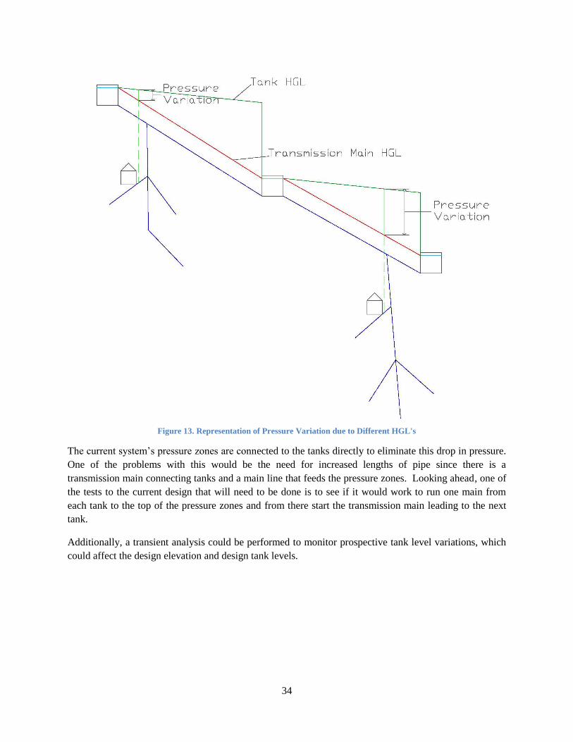
34
Figure 13. Representation of Pressure Variation due to Different HGL's
The current system’s pressure zones are connected to the tanks directly to eliminate this drop in pressure.
One of the problems with this would be the need for increased lengths of pipe since there is a
transmission main connecting tanks and a main line that feeds the pressure zones. Looking ahead, one of
the tests to the current design that will need to be done is to see if it would work to run one main from
each tank to the top of the pressure zones and from there start the transmission main leading to the next
tank.
Additionally, a transient analysis could be performed to monitor prospective tank level variations, which
could affect the design elevation and design tank levels.

35
6. CHLORINATION BENCH STUDY A bench scale study of the chlorine dosing injector pumps is scheduled for the second semester of the
project. By testing the ability of selected injector pumps to deliver a dose that responds well to changes in
flow rate, the team will be able to better recommend a dosing pump for use in the chlorination system in
Apatug.
Fluid-driven proportional injectors are used throughout the industries of agriculture, food service, and
farming to ensure the precise administration of water soluble chemicals to a water supply. Currently, there
is no precedent set for the sustained treatment of a municipal water supply using this technology. Water
quality standards are much more stringent for humans than they are for livestock and crops, thus due
diligence must be performed before deployment can begin. The purpose of the bench scale study is
twofold: (1) to become familiar with the operations of the selected injector, its setup, and maintenance
and (2) to establish if the injector creates the anticipated chlorine residual by responding to changes in
flow. Figure 14 shows the preliminary process design of the bench scale study.
Figure 14. Bench Scale Design
The first step will be to run a control test with deionized water and 5% NaOCl to get a chlorine residual
concentration of 0.3 mg/L. Once the system is calibrated the deionized water will be replaced with water
treated to match the conditions of that in Apatug. The system experiment will be recalibrated and repeated
to develop the 0.3 mg/L residual suggested by Bruce Rydbeck. After calibration, the flows will then be
varied to test how well the injector responds and if the residual can maintained. Finally, any dosing
calculations that were made to theoretically calibrate the injector will be modified to more accurately
reflect the water composition in Apatug.

36
7. TRIP TO ECUADOR The ACE Team will travel to Ecuador during January. This trip will be separated into two components,
with two team members traveling from January 19-January 31, and two more from January 24-January
31. The second pair cannot travel for the full two weeks due to an interim special topics course which is
required for graduation. The first pair of students to travel, Wendy and Julie, will meet up with the ACE
Team’s client, Bruce Rydbeck, and tour Apatug to determine the best location for reservoirs and other
proposed structures as well as connecting with members of the Apatug community. When the second pair
of Mark and Nathan arrives, the four team members, along with Mr. Rydbeck, will travel around to other
current water and chlorination systems to get a better understanding for the methods that are most
successful in similar settings. These community visits will allow the four members of the group to get a
better understanding for what is culturally appropriate as the system is finalized and chlorination design
begins. The team will do some chlorine monitoring while also looking at the chemical make-up of the
water in Apatug, so conditions can be duplicated for the bench-scale model the team hopes to build. The
trip will also allow the group to make a personal connection with the community. Asking the community
leaders for input in regards to reservoir location is important in the success of the system as the
community becomes involved and they feel more responsible for the system, increasing the chance that
the system is maintained and is reliable for years to come.
7.1 Trip Goals There are two important reasons for the team to travel to Ecuador and visit the community of Apatug.
First, testing of the source water quality in Apatug is needed to determine chlorine dosing requirements.
Second, a trip to Apatug will be crucial in the sustainability of the design, which requires community
involvement and ownership. This water distribution system is scheduled to be implemented after the
completion of the design recommendation, and for the system to be sustainable, ownership and
investment from Apatug is extremely important.
Specific goals for the trip include:
1. Implementation of water testing in Apatug to determine chlorine dosing requirements
2. Tour of local chlorination systems
3. Investigate local electrolysis equipment used for chlorine production
4. Meet with the community and establish a positive, working relationship
5. Select potential reservoir locations and confirm pipe network layout
6. Learn local construction methods and materials
7. Gather any cultural information relevant to the final design
7.2 Tentative Itinerary
January 19 Wendy and Julie arrive in Quito
20 Design meeting in Quito in the morning and then leave for Apatug
20-22 Work in Apatug on information gathering, meet with the community to discuss layout of
proposed structures, etc.
23 Leave Apatug by noon for Quito to pick up Nathan and Mark
24 Visit the Indian market in Otavalo and then tour the Carabuela water system and take
chlorine measurements
25 Sunday - attend worship service and do some sightseeing in Quito

37
26 Leave for Apatug for final day of work in the community
27 Tour of local water lab in Cajabamba and chlorine production facilities
28-30 Tour of community water systems in several communities and chlorine monitoring
30 Return to Quito
31 Leave for the U.S.
The team will be hosted by Bruce Rydbeck and Cesar Cortez, who will accompany the team during the
duration of the trip. [44]
7.3 Water Testing Plan
7.3.1 Purpose
Performing field water testing while in Ecuador will be important in determining source water quality and
composition, both of which are critical in chlorine dosing for effective disinfection. Having an accurate
representation of the chemical composition of the source water will be useful in performing a chlorination
bench study. In addition, knowledge of source water quality, turbidity, pH, and temperature fluctuations
are imperative for effective chlorine dosing.
7.3.2 Objectives
1. To determine the bacterial concentration of the protected spring water that supplies the
community of Apatug with drinking water.
2. To determine the chemical composition of the protected spring water for the purposes of chlorine
dosing and bench study design.
3. To determine the turbidity, pH, and temperature of the protected spring water to calculate
chlorine dosing for sufficient disinfection.
4. To perform water quality measurements under a variety of conditions, including high and low
flow and different times of day to more accurately determine daily fluctuations in water quality, if
any.
7.3.3 Key Parameters
1. Natural Organic Matter (NOM)
NOM is typically measured by filtering the water sample and analyzing the sample for Total
Organic Carbon (TOC). TOC measurement requires expensive field equipment, but a turbidity
measurement can be an indicator of the concentration of organic solids in water. NOM
concentration is relevant in determining proper chlorine dosing because chlorine reacts with
NOM to form byproducts. [45]
2. Turbidity
Turbidity, measured in NTU, is an indicator of suspended solids and colloids concentration in a
liquid. Measured by quantifying the amount of light that is able to pass through a water sample,
turbidity is especially important in determining the effectiveness of UV disinfection. However,
turbidity also impacts disinfection efficiency, with higher turbidity levels resulting in lower free
chlorine concentration due to the oxidation of organic matter. [45] Turbidity meters can be
purchased and used in the field, costing in the range from $1000 to $2000 from Hach Company.

38
Alternatively, a Secchi disk method can be used to visually determine turbidity. As shown in
Figure 15, a Secchi disk is placed at the bottom of a clear tube which is filled with sample water
until the Secchi disk can no longer be seen. The depth of the sample water corresponds to the
turbidity of the sample. Secchi disks are inexpensive to construct, but they do not provide the
same accuracy as the manufactured turbidity meters.
Figure 15. Schematic of a Secchi Disk as a Turbidity Measurement [46]
The pH of water is a measure of the acidity or basicity of an aqueous solution. pH affects the
efficiency of chlorine disinfection, with lower pH being more efficient for disinfection.
According to U.S. Army Public Health Command, source water pH should be below 8 for
effective chlorination. [45]
3. Temperature
Chlorine disinfection is also affected by the temperature of the source water, with higher
temperatures yielding faster disinfection. [45]

39
4. Ammonia
Ammonia reacts with chlorine in water, affecting the amount of free chlorine available for
disinfection. [47] Ammonia concentration can be measured using a Hach Water Testing Kit.
5. Coliforms
Bacterial coliforms give an indication of potential pathogenic bacteria that pollute drinking water
sources. [48]
6. Hydrogen sulfide
Hydrogen sulfide reacts with chlorine, reducing its effectiveness as a disinfectant. [46] Hydrogen
sulfide is also an indicator of pathogenic bacteria, as it is produced by fecal coliforms. [46]
7.3.4 Field Test Plan
Since the community of Apatug currently receives all of its drinking water from a single protected spring,
the spring water delivered to the village through the existing feedline shall be tested for relevant water
quality parameters.
Test Parameters
1. Turbidity, 6 grab samples
2. Temperature, 6 grab samples
3. pH, 6 grab samples
4. Ammonia, 2 composite samples (6 water samples collected over 2 days)
5. Hardness, 2 composite samples (6 water samples collected over 2 days)
6. Chloride, 6 grab samples
7. Alkalinity, 2 composite samples (6 water samples collected over 2 days)
8. Bacterial coliforms, 6 grab samples
9. Hydrogen sulfide, 2 composite samples (6 water samples collected over 2 days)
The source water will be tested in the morning, in the afternoon, and at night to represent current drinking
water at different times of the day, including during high and low water demand. Water quality analysis
tests will also be performed on three different days to provide an idea of the range of chemical and
bacterial concentrations of the source water. The schedule and times of the water testing may be altered
after visiting the village and determining more accurate water usage patterns. In total, a minimum of nine
tests for each parameter are needed to compete the water survey.
Equipment and Cost Equipment sources and costs are summarized in
Table 3.

40
Table 3. Water Testing Equipment and Cost Estimates.
Test Parameter Equipment Source Estimated Cost
Gloves Calvin College --
Plastic test tubes Calvin College --
Turbidity Secchi disk and tube Self-constructed $ 5
Temperature Nine-Parameter Test Kit
Model FF-1A
Hach
$ 299
pH
Ammonia
Hardness
Chloride
Alkalinity
Bacterial coliforms Petrifilm Coliform
Count Plates
3M $ 55
Hydrogen sulfide H2S Test Kit Hach $ 25
Total Estimated Cost $ 384

41
8. PROJECT FEASIBILITY CONCLUSION
8.1 Cost Analysis The following is a detailed cost analyses of the proposed distribution system to date, December 6, 2014.
8.1.1 Distribution System Cost
Table 4 shows a summary of the different pipe diameters that have been selected in the current design up
until this point. The unit cost of PVC pipe from a similar project can be seen in Table 5. These prices are
just preliminary, when the design is finalized current unit prices will be obtained from Bruce Rydbeck.
An estimate at the total cost given the rough lengths and prices shown below would be $52,317.31.
Home connections will need to be made wherever possible. However, it is unknown how many home
connections will be made or how many spigots that translates into for the homes without indoor
plumbing. A more detailed cost analysis will be given in the design report.
Table 4. Preliminary Pipe Lengths Estimate
Nominal Diameter
(mm)
Inner Diameter
(mm)
Total Length
(m)
40 36.2 4487
50 45.2 2912
63 57 2877
75 69.2 1866
TOTAL 12142
Table 5. Unit Cost of Similar Projects [49]
Nominal Diameter
(mm) Unit Cost (US$/m)
40 2.69
50 3.60
63 5.52
75 7.44
8.1.2 Chlorination Dosing System Cost
Table 6 shows the preliminary cost of the chlorine dosing system. These costs will be finalized and more
detail will be made available after the trip to Apatug in January 2015.

42
Table 6. Preliminary Dosing System Cost Estimate
Parts List Cost
MiniDos Injector 12gpm $550.00
PVC Compression Stop & Waste Valve (Inlet Valve) $8.95
Outlet Valve (Same as above) $8.95
Water Hammer Arrestor, 3/4 In MNPT, Copper $45.60
Suction Tube $2.00
4 in. x 4 in. x 3/4 in. Schedule 40 PVC Reducing Tee X 2 $27.92
Joints and other fittings $100.00
Contingency $74.34
Total $817.76
8.2 Sustainability Study The National Research Council has defined a sustainable water system as follows:
“A sustainable water system is one that can meet performance requirements over the long
term. Such systems have the following characteristics (Wade Miller Associates, 1991;
Okun, 1995): a commitment to meet service expectations; access to water supplies of
sufficient quality and quantity to satisfy future demand; a distribution and treatment
system that meets customer expectations and regulatory requirements; and the technical,
institutional, and financial capacity to satisfy public health and safety requirements on a
long-term basis. Like any good business, a sustainable water system can also adapt to
future changes in regulatory requirements and customer demand.… Achieving
sustainability is not a onetime task; it requires a continuous effort.” [12]
Furthermore, Breslin, CEO of Water For People, states that project “success will require less single-
minded focus on the absolute number of people without access to water and sanitation facilities and more
focus on the serious questions around long-term impact and sustainability.” [13] This water distribution
system and chlorination dosing system will be designed in a way that achieves this criterion.
One of the main ways that Apatug’s system will be designed for future sustainability will be to place all
main lines in the street. When it is fit to do so, a main line will divert off of the street to service homes.
But this will only be done in cases where it is deemed necessary; when five or more homes are not on a
main road. For all other cases, the homes will have direct connections off of the main line in the street.
By laying the majority of the pipe for the system in the already established streets, it allows for natural
growth of the community of Apatug without any need to reallocate pipelines. Since agriculture is a large

43
part of the community of Apatug, the fields will not see any adverse effects as to implementation of this
distribution system. Placing pipes in the street also minimizes disturbance to existing buildings and fields,
and it will not occupy spaces that are likely be developed in the future.
Creating a water distribution system is a step towards a sustainable development for Apatug. However,
the design must also be sustainable overall. For the design to be sustainable, it must be reliable and last a
long time with minimal required maintenance. Some of the design decisions that are affected by
reliability are as follows: reservoir design, pipe diameter and thickness, and chlorination dosing method.
The chlorination dosing is a major component of reliability, because if the dosing mechanism does not
work properly, the water that is received in homes will not be properly disinfected. Failure to dose
effectively would result in inadequate disinfection and would not be following the Ecuadorian law
requiring chlorination. [24] If pipes are too small or the pipe wall is too thin, they will experience too
much pressure and rupture.
This design needs to be sustainable in its cost effectiveness as well. Cost of materials could have a
significant impact on the frequency and manner of maintenance of the system. The selection of materials
needs to be made with cost in mind, as well as strength, in order to prevent future breaks in the system.
Whereas communities in the United States rely on taxpayer money and public works programs, Apatug
does not have the infrastructure in place to give maintenance responsibilities to a third party. By
designing the system with cost in mind it will be sustainable for the village and will not be a crippling
blow if a fix needs to be made.
Because Apatug is a rural community, the need for environmental stability needs to be met as well. Some
of the villagers work in fields within the community to make their living. The design and construction
needs to be completed in a way that does not significantly affect the environment or landscape. When
selecting materials to use, this will be a key aspect. The pipes will need to be joined together in the
construction process in a way that is clean and does not leave behind any unwanted environmental
hazards.
Community trust in the system and especially in the chlorination are major factors in the sustainability of
the system. If the community does not trust the chlorination because it affects the taste, then the system
most likely will not fulfill its potential. Community trust is one of the major factors in the success of a
rural water distribution system. Most communities throughout the world have some sort of political
structure that makes major decisions for the community. Working through and understanding this
political structure instead of forcing the design on the community can have a major impact on whether the
project is a success. [24] One of the main components of this design is working with the community to
decide where the reservoirs should be placed. If the community does not trust the system, then it will not
be used as intended and lose the sustainability factor in return.
8.3 Distribution System Design In order to control pressures in the system and supply each household with clean water, the team proposes
a distribution network preliminary design, as detailed and shown in Appendix E. The team has designed
the system using five reservoirs to control five pressure zones, in order to maintain adequate pressures in
the range of 20 to 60 meters at the household connections. This was chosen over the use of PRVs
throughout the system to provide a reliable, flexible, and sustainable distribution network. The team then
created a preliminary model in EPANET that can be updated and changed based on interactions with the

44
community in January. The design based on this model will then be corroborated with Church’s tabular
method to illustrate its consistency with commonly used methods. The currently proposed lengths of
pipes of each diameter can be found in Table 4.
More testing and final design will be performed in the coming semester after more information is
gathered from the community and its leaders in January.
8.4 Proposed Chlorination System After evaluating chlorination alternatives, the team selected liquid sodium hypochlorite as the disinfection
chemical for the Apatug system. Liquid hypochlorite is widely available in Ecuador and leaves residual
chlorine in the distribution system when dosed properly. The chlorine dosing system will consist of a
chlorination building to house the chlorine solution, dosing injector pumps, and other necessary valves
and operating equipment, including chlorine test strips and check valves. The chlorination building will
receive water from the main pipeline from the protected springs, dose the chlorine solution into the spring
water, and transport the chlorinated water to a reservoir, which will also serve as a contact tank. A
preliminary drawing of the chlorine dosing building is included in Appendix F. A process flow diagram
of the chlorination system is shown in Figure 16.
Figure 16. Process Flow Diagram for Chlorine Dosing.
Initial calculations, included in Appendix G, assuming a flow range of 1 to 5 L/s, a minimum water
temperature of 50 °F, and a maximum pH of 8, were used to determine an effective volume necessary for
the contact tank of 16 m3. The required volume for the contact tank will be determined by the contact time
necessary for disinfection of the source water. Field chemical analysis and water quality tests performed

45
in Apatug will be necessary to determine a more accurate contact time and tank volume needed in the
system.
The proposed reservoir at the highest elevation is recommended to be 3490 m, which will also be the
elevation of the dosing station and contact tank. However, the dosing system will not be greatly affected
by its elevation, provided there is a sufficient amount of head to drive water through the dosing pump.
The last distribution tank located on the existing pipeline from the springs before reaching Apatug is at an
elevation of 3521 m, which will provide a sufficient amount of pressure to drive flow through a pump at
3490 m.
Initial flow calculations through the dosing injector pump were performed using specifications from
MixRite 3.5, a proportional flow fluid-driven injector pump. Using these specifications and a 5% solution
of sodium hypochlorite, it was determined that a shunt flow of 0.02 to 0.10 L/s is needed to drive the
injection pump. Using this initial shunt flow calculation, a chlorine dose ranging from 1:2114 to 1:503
would be provided by the injector pump, which is consistent with the specifications from the MixRite 3.5,
included in Appendix D.

46
9. BASIS OF DESIGN
9.1 Distribution System Design The preliminary distribution network model is provided in the AutoCAD plot in Appendix E. A summary
of pipe diameters and lengths, as well as the size of the proposed reservoirs, is provided in Error!
Reference source not found.. Apatug has been divided into five pressure zones to keep pressure within
the 20-60 meter range. Each node on the network represents five homes and there are about 100 nodes
total. Geographical information from a survey done of Apatug was converted into an AutoCAD file.
Based on the AutoCAD file a model was created EPANET 2.0, as seen in Figure 17. The EPANET file
can be found at the team’s website at: www.calvin.edu/academic/engineering/2014-15-team19.
Figure 17. EPANET Model of Apatug with Elevations

47
Table 7. Summary of Distribution System Components
9.2 Chlorination System Design Dosing of chlorine will be performed by a fluid-driven proportional injector calibrated to deliver a
residual of 0.3 mg/L. This type of pump is preferred for Apatug because it can maintain a constant
residual through the 1-5 L/s flow range. A shunt off the main water line will necessary to motivate the
injector. After mixing, the water requires a sufficient contact time inside of a reservoir to get full kill of
pathogens. The first reservoir at a volume of 20 m3 will serve as the contact tank.
9.3 Chlorination Bench Scale Study The bench scale study will be performed in Calvin College’s Environmental Engineering Research lab. A
preliminary schematic of the design is provided in Figure 14. Most of the equipment will be provided by
Calvin College except for the fluid-driven injector which will be purchased by the team. The water used
for the experiment will be created to match water samples taken during the team’s trip to Ecuador in
January.
9.4 Future Work The next step for the ACE Team is to travel to Apatug in January of 2015. While in Apatug, the team will
meet with the community to finalize the water distribution network layout and reservoir placement. Water
quality and chemical analysis tests will also be performed to inform the chlorination dosing design. The
trip to Ecuador will also provide an opportunity for the team to communicate with the community of
Apatug, in keeping with the design norms of cultural appropriateness and transparency.
The spring semester will consist of detailed plans for the water distribution system, including final pipe
layout, reservoir design and placement, connections, valves, and the installation of water meters. A bench
study will also be performed to select a dosing method for chlorine disinfection. A detailed plan for the
chlorination system will also be formulated in the spring.
Reservoir Size
(m3) Count
Nominal Pipe
Diameter (mm)
Length of Pipe
(m)
15 1 40 4487
20 1 50 2912
35 1 63 2877
40 1 75 1866
55 1
Total Count 5 Total Length 12142
Pipe NetworkReservoirs

48
10. AKNOWLEDGEMENTS The ACE team would like to formally thank the following individuals for graciously offering their time
and knowledge to the success of this project:
David Wunder of the Calvin College Engineering Department, for offering his insight and advice to the
team on a weekly basis; Robert Hoeksema of the Calvin College Engineering Department for offering his
expert knowledge of EPANET and guiding the team through the entire process of distribution system
modeling; Bob DeKraker of the Calvin College Engineering Department for assistance in installing
modeling software; Tom Newhof Sr. of Prein&Newhof for meeting with and advising the team as an
industrial consultant; Bruce Rydbeck of Life Giving Water International for providing this project to us,
coordinating our trip to Ecuador in January, and supplying the team with information to make this project
successful; and Cesar Cortez of Reach Beyond for providing GPS data of Apatug and answering the
questions of the team.

49
11. REFERENCES [1] "Calvin College Engineering," [Online]. Available:
http://www.calvin.edu/academic/engineering/about/mission.html.
[2] B. Rydbeck, [Email Correspondence]. 15 October 2014.
[3] B. Rydbeck, [Email Correspondence]. 10 September 2014.
[4] United Nations Economic and Social Council, "General Comment No. 15," 29 November 2002.
[Online]. Available: http://www2.ohchr.org/english/issues/water/docs/CESCR_GC_15.pdf.
[Accessed 5 December 2014].
[5] United Nations Department of Economic and Social Affairs (UNDESA), "International Decade
for Action 'WATER FOR LIFE' 2005-2015," 5 May 2014. [Online]. Available:
http://www.un.org/waterforlifedecade/human_right_to_water.shtml. [Accessed 5 December
2014].
[6] United Nations, "Millennium Development Goals and Beyond 2015," [Online]. Available:
http://www.un.org/millenniumgoals/environ.shtml. [Accessed 5 December 2014].
[7] Republic of Ecuador, "Constitution of 2008," 31 January 2011. [Online]. Available:
http://pdba.georgetown.edu/Constitutions/Ecuador/english08.html. [Accessed 20 September
2014].
[8] B. Rydbeck, [Email Correspondence]. 19 September 2014.
[9] B. Rydbeck, [Email Correspondence]. 27 November 2014.
[10] J. C. Church, Practical Plumbing Design Guide, New York: McGraw-Hill, Inc., 1979.
[11] World Bank, "World Development Indicators," [Online]. Available:
http://data.worldbank.org/data-catalog/world-development-indicators. [Accessed 2 November
2014].
[12] National Research Council (U.S.), Safe Water from Every Tap: Improving Water Service to
Small Communities, Washington D.C.: National Academy Press, 1997.
[13] E. D. Breslin, "Rethinking Hydro-Philanthropy: Smart Money for Transformative Impact,"
Journal of Contemporary Water Research & Education, vol. 145, no. 1, pp. 65-73, 2010.
[14] D. A. Okun, "A Water and Sanitation Strategy for the Developing World," Environment, vol. 33,
no. 8, pp. 20, 39-40, 1991.
[15] G. Pearce-Oroz, "Rural Water Supply and Sanitation Challenges in Latin America for the Next
Decade," in Cusco+10, Lima, Peru, 2011.
[16] M. Munasinghe, "The pricing of water services in developing countries," Natural Resources
Forum, vol. 143, 1990.

50
[17] A. Gadgil, "Drinking water in developing countries," Annual Review of Energy and the
Environment, vol. 23, no. 253, pp. 282,284, 1998.
[18] J. Briscoe and D. M. De Ferranti, Water for rural communities: helping people to help
themselves, Washington, D. C.: World Bank, 1988.
[19] S. P. Andey and P. S. Kelkar, "Influence of intermittent and continuous modes of water supply on
domestic water consumption," Water Resources Management, vol. 23, no. 12, pp. 2555-2566,
2009.
[20] US Environmental Protection Agency Office of Water, "2006 Community Water System
Survey," 2009.
[21] J. Guerrero, C. Kluge, M. Spee and J. Voogt, "Senior Design Final Report: Water Systems
Design for Cajabamba, Ecuador," Calvin College, Grand Rapids, MI, 2008.
[22] A. Braghetta, "Drawing the connection between Malnutrition and lack of safe drinking water in
Guatemala," American Water Works Association, vol. 98, no. 5, pp. 97-106, 2006.
[23] M. M. Mao, K. J. Zhang, T. Q. Zhang and H. L. Yu, "Research Progress of Typical Taste and
Odor Compounds Produced by Chlorination in Drinking Water," Applied Mechanics and
Materials, p. 698, 2013.
[24] Ecuadorian Standardization Institute, "Drinking-water Requirements," NTE INEN 1108, 2010.
[25] L. A. McLaughlin, K. Levy, N. K. Beck, G. A. Shin, J. S. Meschke and J. N. Eisenberg, "An
observational study on the effectiveness of point-of-use chlorination," Journal of Environmental
Health, vol. 71, no. 8, pp. 48-53, 2009.
[26] International Programme on Chemical Safety, "2. Chemistry of Disinfectants and Disinfectant
By-products," in Environmental Health Criteria 216: Disinfection and Disinfectant By-products,
Geneva, World Health Organization, 2000, pp. 27-109.
[27] Food & Water Watch, "Chloramine: A Chlorine Alternative in Drinking Water Fact Sheet,"
Vermonters for a Clean Environment, April 2010. [Online]. Available:
http://www.vce.org/FWWchloramine.pdf. [Accessed 14 October 2014].
[28] National Academy of Sciences, "Treatment: Chemical Disinfection/ Oxidants Technologies,"
Drinking-Water.org, 2008. [Online]. Available: http://www.drinking-
water.org/html/en/Treatment/Chemical-Disinfection-Oxidants-technologies.html. [Accessed 14
October 2014].
[29] B. Rydbeck, [Email Correspondence]. 9 October 2014.
[30] "Electrochemistry: Interactive Student Tutorial," Prentice Hall, [Online]. Available:
http://wps.prenhall.com/wps/media/objects/4680/4792445/ch18_12.htm. [Accessed 7 November
2014].

51
[31] United States Environmental Protection Agency, "4. Chlorine Dioxide," in EPA Guidance
Manual: Alternative Disinfectants and Oxidants, U.S. EPA, 1999, pp. 4-1 - 4-41.
[32] Dosmatic, "The Dosmatic Advantage Operation and Installation Manual for All A15 Models,"
HydroSystems, 2001.
[33] B. V. Rydbeck and B. Vander Plas, "Rural Water System Disinfection Pilot Project for
Carabuela, Ecuador," 2013.
[34] Tubosistemas Plastigama de Amanco, "Tuberias y accesarios de PVC y PE BD Uso Agricola".
[35] Great Lakes Upper Mississippi River Board of Water, Recommended Standards for Water
Works, 1992.
[36] American Water Works Association, Distribution Network Analysis for Water Utilities M32,
Denver, CO: American Water Works Association, 1989.
[37] B. Rydbeck, [Email Correspondence]. 9 September 2014.
[38] L. W. Mays and T. M. Walski, "Hydraulic Design of Water Distribution Storage Tanks," in
Water Distribution Systems Handbook, New York, McGraw-Hill, 2000, p. 10.1.
[39] Environmental Protection Agency, 15 August 2002. [Online]. Available:
http://water.epa.gov/lawsregs/rulesregs/sdwa/tcr/upload/2007_05_18_disinfection_tcr_whitepape
r_tcr_storage.pdf. [Accessed 26 November 2014].
[40] B. Rydbeck, [Email Correspondence]. 4 November 2014.
[41] United States Environmental Protection Agency, "EPANET," U.S. EPA, 8 July 2014. [Online].
Available: http://www.epa.gov/nrmrl/wswrd/dw/epanet.html. [Accessed 10 October 2014].
[42] L. W. Mays, Water Resources Engineering, Second ed, United States: John Wiley & Sons, Inc.,
2010.
[43] B. Rydbeck, [Email Correspondence]. 13 November 2014.
[44] B. Rydbeck, [Email Correspondence]. 18 November 2014.
[45] U.S. Army Public Health Command, "Chlorine Disinfection in the Use of Individual Water
Purification Devices: Technical Information Paper #31-002-0306," phc.amedd.army.mil.
[46] J. Kearns, "Simple Field Tests for Water Quality," Aqueous Solutions, January 2008. [Online].
Available: http://www.aqsolutions.org/images/2008/01/simple-field-tests-for-water-quality.pdf.
[Accessed 5 November 2014].
[47] Fisheries and Aquaculture Department, "Chapter 2 - Water Quality Monitoring, Standards, and
Treatment," Food and Agriculture Organization, 2013. [Online]. Available:
http://www.fao.org/docrep/x5624e/x5624e05.htm#2.2.3 bacteriological tests. [Accessed 5
November 2014].

52
[48] "Chlorine, Coliform, and pH Test Kit, Model CEC-2 (with 120 Vac UV Lamp and Incubator,"
Hach Company, 2014. [Online]. Available: http://www.hach.com/chlorine-coliform-and-ph-test-
kit-model-cec-2-with-120-vac-uv-lamp-and-incubator/product?id=7640249600. [Accessed 5
November 2014].
[49] M. A. Niskanen, "The Design, Construction, and Maintenance of a Gravity-Fed Water System in
the Dominican Republic," Michigan Technological University, 2003.
[50] B. V. Rydbeck and M. Yamez, "Sustainable Water Quality for Rural Ecuadorian Communities,"
2012.
[51] P. G. Bourne, Water and Sanitation Economic and Sociological Perspectives, Orlando: Academic
Press, Inc., 1984.

A-1
Appendix A – Gantt Chart

ID Task
Mode
Task Name Duration Start Finish
1 Project Proposal 6 days Wed 9/3/14 Wed 9/10/14
2 PPFS Outline Draft 11 days Thu 9/11/14 Thu 9/25/14
18 Chlorination Research 11 days Tue 10/7/14 Tue 10/21/14
19 Distribution Research 11 days Tue 10/7/14 Tue 10/21/14
21 Apatug & Ecuador Research 11 days Tue 10/7/14 Tue 10/21/14
8 Assign Project Roles 3 days Wed 10/8/14Fri 10/10/14
22 Design Logo 3 days Wed 10/8/14Fri 10/10/14
28 Material Availability Research 6 days Wed 10/8/14Wed 10/15/14
29 Special Topics Proposal 6 days Wed 10/8/14Wed 10/15/14
5 Oral Presentation I 4 days Wed 10/15/14Mon 10/20/14
14 Project Brief 4 days Wed 10/15/14Mon 10/20/14
15 Team Photos 4 days Wed 10/15/14Sun 10/19/14
30 January Trip Planning 38 days Thu 10/16/14Mon 12/8/14
16 PPFS Draft 1 6 days Mon 10/20/14Sun 10/26/14
23 GIS and Survey to EPANET 6 days Mon 10/20/14Sat 10/25/14
4 Chlorine Decision Matrix 6 days Mon 10/27/14Sun 11/2/14
10 Project Poster 5 days Mon 10/27/14Fri 10/31/14
11 PPFS Draft 2 6 days Mon 10/27/14Sun 11/2/14
24 Preliminary EPANET Model 31 days Mon 10/27/14Sun 12/7/14
3 Dosing Decision Matrix 6 days Mon 11/3/14Sun 11/9/14
9 Project Website 11 days Mon 11/3/14Mon 11/17/14
13 PPFS Draft 3 6 days Mon 11/3/14Sun 11/9/14
20 Water Testing Plan for January 6 days Mon 11/3/14Mon 11/10/14
7 Industrial Consultant Meeting 5 days Tue 11/4/14 Mon 11/10/14
31 Bench Study Design 24 days Wed 11/5/14Sun 12/7/14
12 PPFS Total Draft and Review 6 days Mon 11/10/14Mon 11/17/14
17 PPFS Final 20 days Tue 11/11/14Mon 12/8/14
25 Reservior Design Research 16 days Wed 11/12/14Wed 12/3/14
26 Unit Cost Estimate 4 days Wed 11/12/14Mon 11/17/14
6 Oral Presentation II 3 days Thu 11/20/14Mon 11/24/14
27 Cost Estimate 7 days Fri 11/28/14 Sun 12/7/14
32 Preliminary AutoCAD Drawing 4 days Wed 12/3/14Sun 12/7/14
T W T F S S M T W T F S S M T W T F S S M T
Sep 7, '14 Sep 14, '14 Sep 21, '14
Task
Split
Milestone
Summary
Project Summary
Inactive Task
Inactive Milestone
Inactive Summary
Manual Task
Duration-only
Manual Summary Rollup
Manual Summary
Start-only
Finish-only
External Tasks
External Milestone
Deadline
Progress
Manual Progress
Page 1
Project: ProjectDraft1
Date: Mon 12/8/14

W T F S S M T W T F S S M T W T F S S M T W T F S S M T W T F S S M T W T F S
Sep 28, '14 Oct 5, '14 Oct 12, '14 Oct 19, '14 Oct 26, '14 N
Task
Split
Milestone
Summary
Project Summary
Inactive Task
Inactive Milestone
Inactive Summary
Manual Task
Duration-only
Manual Summary Rollup
Manual Summary
Start-only
Finish-only
External Tasks
External Milestone
Deadline
Progress
Manual Progress
Page 2
Project: ProjectDraft1
Date: Mon 12/8/14

S M T W T F S S M T W T F S S M T W T F S S M T W T F S S M T W T F S S M T W
Nov 2, '14 Nov 9, '14 Nov 16, '14 Nov 23, '14 Nov 30, '14 Dec 7, '14
Task
Split
Milestone
Summary
Project Summary
Inactive Task
Inactive Milestone
Inactive Summary
Manual Task
Duration-only
Manual Summary Rollup
Manual Summary
Start-only
Finish-only
External Tasks
External Milestone
Deadline
Progress
Manual Progress
Page 3
Project: ProjectDraft1
Date: Mon 12/8/14

B-1
Appendix B – Disinfection Decision Matrices
Figure B.1. Decision Matrix for Chlorine Dosing Method
Figure B.2. Decision Matrix for Disinfection Chemical

C-1
Appendix C – Pressure Zone and Tank Mathcad and Excel Calculations Calculations: Wendy Tabler 11/6/14
Checked By: Jeremy Kamp 11/7/14
20-60 meter range (5 Zones)
head min max # households
3326 3266 3306 46
3367 3307 3347 125
3408 3348 3388 167
3449 3389 3429 102
3490 3430 3470 18
Reservoir Sizing Size (m3)
Zone 1 (Lowest Elevation) 15
Zone 2 40
Zone 3 55
Zone 4 35
Zone 5 (Highest Elevation) 20

D-1
Appendix D – Injector Pump Specifications for MixRite and Dosmatic®

D-2

D-3

D-4

D-5

E-1
Appendix E – Distribution System Schematic


F-1
Figure F.1. Preliminary Chlorine Dosing Station Schematic
Appendix F – Chlorine Dosing Station Schematic

G-1
Appendix G – Chlorine Dosing Mathcad Calculations
Apatug Chlorine Dosing
Calculations: Julie Swierenga 12/3/14
Checked By: Nathan Laframboise 12/5/14
Assumptions
Flow range into chlorine dosing station: 1 – 5 L/s (15 – 79 gpm) [email from Bruce 9/19/14]
Chlorine dosing range: 0.5 – 2 ppm [email from Bruce 9/19/14]
Hypochlorite solution at 5% (1 mol NaOCl to 1 mol free chlorine)
0.3 mg/L free chlorine residual is desired [Rydbeck, Chlorination Pilot Study, 2013]
Highest estimated water pH: 8.0
Lowest estimated water temperature: 50 °F
Highest pH and lowest temperature were used to determine necessary contact time [Cornell,
Chlorination of Drinking Water Factsheet, 2005]
Desired 99.9% removal of giardia and 99.99% removal of viruses
Shunt flow and dosing calculations will be compared to pump specifications for the MixRite 3.5

G-2
Dosing Station
elevation : 3500 - 3510m pressure upstream: 11-21 mH2O
contact tank volume: 16 m3 flow: 1-5 L/s chlorine strength = 5% NaOCl or 50000 ppm
Contact Time
contact Time (CT) in min constant from Cornell Factsheet (k) residual chlorine (r) in (mg/L)
Tank Volume
peak flow
tank volume (v) in m3
Chlorine Dosing
Chlorine dose in relation to flow
0.02 L/s : 9.46 x 10 -6 = 1 : 2114
0.10 L/s : 1.99 x 10 -4 = 1 : 502.5
k 16 r .3
CTk
r53.333
q 5l
s
v CT q 60 s 1.6 104
L v 16 m3
qlowflow 15gpm
strength chlorine.low.5
500001 10
5
chlorinedose.low qlowflow strength chlorine.low 9.464 106
l
s
qhighflow 79gpm
strength chlorine.high2
500004 10
5
chlorinedose.high qhighflow strength chlorine.high 1.994 104
l
s