
Teach Slides10
39
Hybrid Systems Introduction As convention fossil fuel energy sources diminish and the world’s environmental concern about acid deposition and global warming increases, renewable energy sources (solar, wind, tidal, biomass and geothermal etc) are attracting more attention as alternative energy sources. These are all pollution free and one can say eco friendly. These are available at free of cost.
-
Upload
aziz-jamaludin -
Category
Documents
-
view
214 -
download
0
Transcript of Teach Slides10

8/20/2019 Teach Slides10
http://slidepdf.com/reader/full/teach-slides10 1/43
Hybrid Systems
Introduction
As convention fossil fuel energy sources diminish and the
world’s environmental concern about acid deposition and global
warming increases, renewable energy sources (solar, wind, tidal,
biomass and geothermal etc) are attracting more attention as
alternative energy sources.
These are all pollution free and one can say eco friendly.
These are available at free of cost.

8/20/2019 Teach Slides10
http://slidepdf.com/reader/full/teach-slides10 2/43
Hybrid Systems-1
In India, there is severe power shortage and associated power
quality problems.
The quality of the grid supply in some places is characterized by
large voltage and frequency fluctuations, scheduled and unscheduled power cuts and load restrictions.
Load shedding in many cities in India due to power shortage and
faults is a major problem for which there is no immediate
remedy in the near future since the gap between the power
demand and supply is increasing every year.

8/20/2019 Teach Slides10
http://slidepdf.com/reader/full/teach-slides10 3/43
Hybrid Systems-2
In India wind and solar energy sources are available all over the
year at free of cost whereas tidal and wave are coastal area.
Geothermal is available at specific location.
To meet the demand and for the sake of continuity of powersupply, storing of energy is necessary.
The term hybrid power system is used to describe any power
system combine two or more energy conversion devices, or two
or more fuels for the same device, that when integrated,
overcome limitations inherent in either.

8/20/2019 Teach Slides10
http://slidepdf.com/reader/full/teach-slides10 4/43
Hybrid Systems-3
Usually one of the energy sources is a conventional one
(which necessarily does not depend on renewable energyresource) powered by a diesel engine,
while the other(s) would be renewable viz. solar photovoltaic,
wind or hydro. The design and structure of a hybrid energy system obviously
take into account the types of renewable energy sources
available locally, and the consumption the system supports.
For example, the hybrid energy system presented here is a
small-scale system and the consumption of power takes place
during nights.

8/20/2019 Teach Slides10
http://slidepdf.com/reader/full/teach-slides10 5/43
Hybrid Systems-4
The wind energy component will make a more significant
contribution in the hybrid system than solar energy.
Although the energy produced by wind during night can be
used directly without storage.
Battery is needed to store solar and wind energy produced
during the day.
In addition to the technical considerations, cost benefit is a
factor that has to be incorporated into the process of
optimizing a hybrid energy system.

8/20/2019 Teach Slides10
http://slidepdf.com/reader/full/teach-slides10 6/43
Hybrid Systems-5
In general, the use of wind energy is cheaper than that of solar
energy.
In areas where there is a limited wind source, a wind system
has to be over-dimensioned in order to produce the required power, and this results in higher plant costs.
It has been demonstrated that hybrid energy systems
(renewable coupled with conventional energy source) can
significantly reduce the total life cycle cost of a stand alone
power supplies in many off-grid situations.

8/20/2019 Teach Slides10
http://slidepdf.com/reader/full/teach-slides10 7/43
Hybrid Systems-6
while at the same time providing a reliable supply of electricity
using a combination of energy sources.
Numerous hybrid systems have been installed across the world,
and expanding renewable energy industry has now developedreliable and cost competitive systems using a variety of
technologies.
Research in the development of hybrid systems focused on the
performance analysis of demonstration systems and
development of efficient power converters.
8/20/2019 Teach Slides10
http://slidepdf.com/reader/full/teach-slides10 8/43
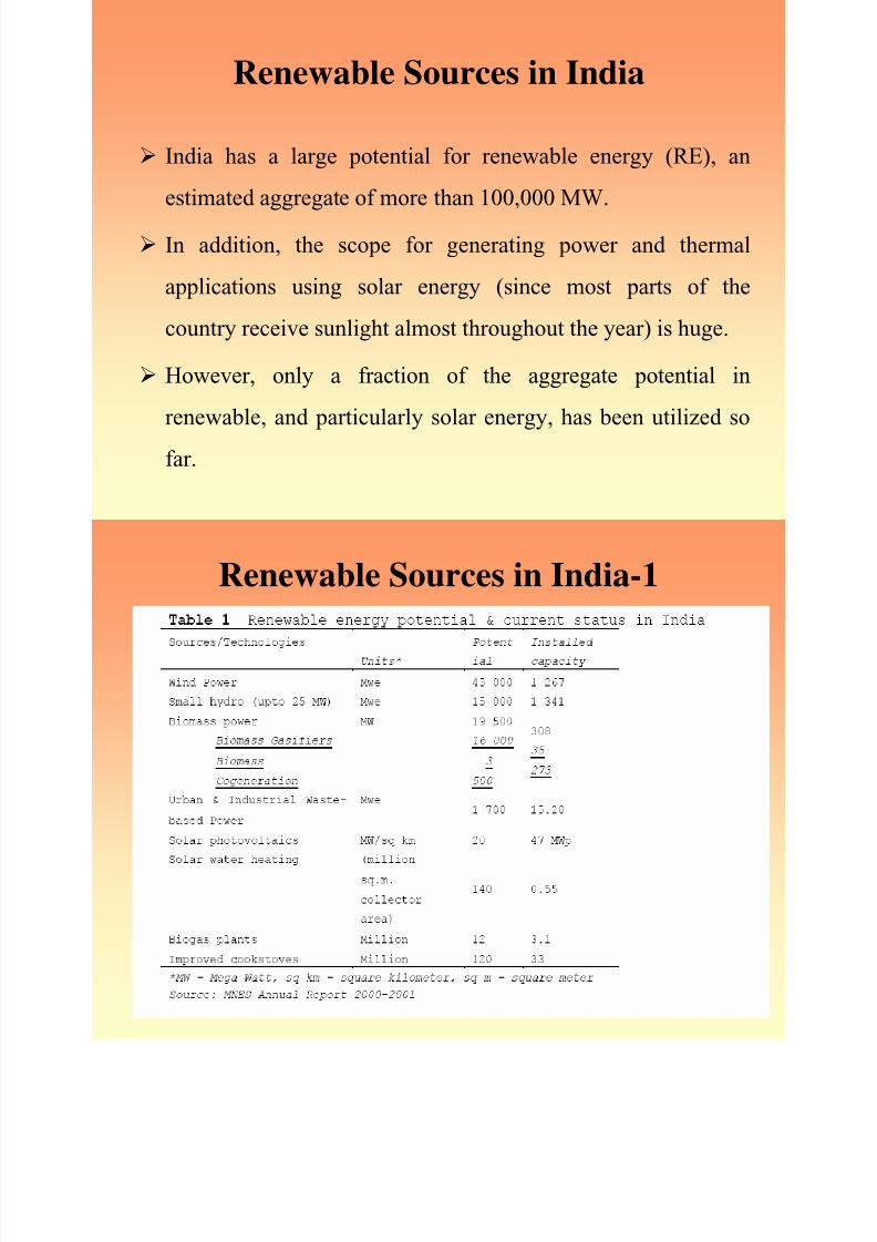
Renewable Sources in India
India has a large potential for renewable energy (RE), an
estimated aggregate of more than 100,000 MW.
In addition, the scope for generating power and thermal
applications using solar energy (since most parts of the
country receive sunlight almost throughout the year) is huge.
However, only a fraction of the aggregate potential in
renewable, and particularly solar energy, has been utilized so
far.

8/20/2019 Teach Slides10
http://slidepdf.com/reader/full/teach-slides10 9/43
Renewable Sources in India-1

8/20/2019 Teach Slides10
http://slidepdf.com/reader/full/teach-slides10 10/43
Hybrid System
LOAD DISCRIPTION :
Here for the purpose of analysis a house of middle class familyis taken as the load.
This is around 2kW.All the hybrid system which are going todiscuss is for a house or for the around 10 no of house (for big
system).Calculation For Power Output From Different Source:
Power out put from PV array: For design of a PV system.
we should know how much solar energy is received at theconcern place.
It is effected by sun position, could covering atmospheric affect,and the angle at which the collector is placed , called tilt angle‘β’.

8/20/2019 Teach Slides10
http://slidepdf.com/reader/full/teach-slides10 11/43
Calculation For Power Output From
Different Source
Normally this angle is equal to the latitude of the concern
place.
The related equation for estimation of the radiation is listed
below [1]:
• Isolation ‘i =Io{ cos ϕ cos δ cos ω + sin ϕ sin δ } kW/m2
• Io = Isc [1 + 0.033 cos (360N/365)] where Isc solar constant.
=1.37 kW/m2
wss
o
wsr
H 'idt= ∫ ωsr = hour angle when sun rising
ωss
= hour angle when sun setting

8/20/2019 Teach Slides10
http://slidepdf.com/reader/full/teach-slides10 12/43
Calculation For Power Output From
Different Source-1
• = (24/π) Isc [1+ 0.033 cos (360N/365)] {cos ϕ cos δ cos ω+ sin ϕ sin δ} kWh/m2 /day
• HoA= energy falling on the concern place considering
atmospheric effect
= K T Ho kWh/m2/day where K T dearness index.
• K T = A1 + A2 sin (t) + A3 sin (2t) + A4sin (3t) + A5 cos (t)
+ A6 cos (2t) + A7 cos (3t)
t = (2π/365) (N-80) N= 1 for Jan 1st

8/20/2019 Teach Slides10
http://slidepdf.com/reader/full/teach-slides10 13/43
Calculation For Power Output From
Different Source-2• Ai = ai1 + ai2 x + ai3 x2 + ai4 w + ai5 w2
Where x = (ϕ - 35)
ϕ = Latitude in degw = total perceptible water vapor in atoms gm/cm2
• Ht = energy falling on the tilt surface at the concern place
= R D HoA kWh/m2 /d• R D = tilted factor
for the sizing the PV panel is given by[1]
W peak = {1/ h peak } [ (Wh((load) * No of no sun days / (η b * no ofdischarging .Days)) + Whload (day) + Whload (night)/ η b)]
• Where: η b = battery efficiency
• h peak = no of hours for which peak insolation falls on thePV cell

8/20/2019 Teach Slides10
http://slidepdf.com/reader/full/teach-slides10 14/43
Power Output From Wind Source
The speed of wind is a random process; therefore it should be
described in terms of statistical methods. The wind speed data were recorded near the ground surface.
To upgrade wind speed data to a particular hub height, the
following equation is commonly used [2]
v = vi- (H/Hi)
• Where: v-wind speed at projected height, H
• vi-wind speed at reference height, Hi
• - Power-law exponent (- 1/7 for open land).

8/20/2019 Teach Slides10
http://slidepdf.com/reader/full/teach-slides10 15/43
Power Output From Wind Source-1
Let
m = Mass (in kg) of the air in the hypothetical cylinder which
radius is equal to the vane lengthv = the velocity of air in m/s.
So kinetic energy
E = m u2 / 2
Power output Pw = (v2/2) × dm/ dt
= ρ× (v2/2) × dQ /dt
= ρ× (v3/2) ×A
Where:
Q = Au = volume of air ρ = 1.2 ( kg/m3 ) (at mean sea level)

8/20/2019 Teach Slides10
http://slidepdf.com/reader/full/teach-slides10 16/43
Power Output From Wind Source-2
Pw = 0.6 A u3
pa = Pw /A = 0.6u3 = power density (in W/m2) [1]Pw is the electrical power output of the turbine.
The available wind generator power output is a function of
wind velocity v
( )
( )
3 3
R c1
R ci3 3R cow
R co R
P V V
forV V VV VP
P 0 for V V V
⎡ ⎤−
≥ ≥⎢ ⎥−= ⎢ ⎥⎢ ⎥≥ ≥⎣ ⎦

8/20/2019 Teach Slides10
http://slidepdf.com/reader/full/teach-slides10 17/43
Power Output From Wind Source-3

8/20/2019 Teach Slides10
http://slidepdf.com/reader/full/teach-slides10 18/43
Calculation Of The Capacity Of The
Battery Bank
The energy generated by Hybrid system involving let say threesource of energy like wind turbine and PV array for hour t,
E G(t) can be expressed as follows:
E G(t) = E 1(t) + E 2(t) + E 3(t)
Where: E i(t) - energy generated ith source
Since it is assumed that the battery charge efficiency is set
equal to the round-trip efficiency and the discharge efficiencyis set equal to 1
we considered two eases in expressing current energy stored
in the batteries for hour t .

8/20/2019 Teach Slides10
http://slidepdf.com/reader/full/teach-slides10 19/43
Calculation Of The Capacity Of The
Battery Bank-1
If the supplied energy from all energy sources exceeds that of
the load demand at a time instant.
The batteries will be charged with the round-trip efficiency:
E B(t) =E B(t-1) + {E G(t) – E L(t) / η charging controller }.η Battery
Where:
• ηcharging controller - efficiency of charging controller
• ηBattery - round-trip efficiency of the batteries.• E B(t) - energy stored in batteries in hour t.
• E B(t-1) - energy stored in batteries in previous hour.
• E L(t) - load demand in hour t.

8/20/2019 Teach Slides10
http://slidepdf.com/reader/full/teach-slides10 20/43
Calculation Of The Capacity Of The
Battery Bank-2
When the load demand is greater than the available energy
generated, The batteries will be discharged by the amount that is needed
to cover the deficit. It can be expressed as follows:
E B(t) = E B(t-1) - { E L(t) / charging controller – E G(t) }
The energy stored in batteries at any hour t is subject to the
following constraint:
E Bmax E B(t) E Bmin
That means that batteries should not be over discharged or
overcharged at any time. That protects batteries from beingdamaged.[2].
8/20/2019 Teach Slides10
http://slidepdf.com/reader/full/teach-slides10 21/43
Feature of Hybrid System
Hybrid systems can address limitations in terms of fuel
flexibility,efficiency, reliability, emissions and / or economics.
Incorporating heat, power, and highly efficient devices (fuel
cells, advanced materials, cooling systems, etc.) can increaseoverall efficiency .
conserve energy for a hybrid system when compared with
individual technologies.
Achieving higher reliability can be accomplished with
redundant technologies and/or energy storage.

8/20/2019 Teach Slides10
http://slidepdf.com/reader/full/teach-slides10 22/43
Feature of Hybrid System-1
Some hybrid systems typically include both, which can
simultaneously improve the quality and availability of power.
• Hybrid systems can be designed to maximize the use of
renewable.
• Resulting in a system with lower emissions than traditional
fossil-fueled technologies.
• Hybrid systems can be designed to achieve desired attributes at
the lowest acceptable cost, which is the key to market
acceptance

8/20/2019 Teach Slides10
http://slidepdf.com/reader/full/teach-slides10 23/43
Wind/PV Hybrid System

8/20/2019 Teach Slides10
http://slidepdf.com/reader/full/teach-slides10 24/43
Wind/PV Hybrid System-1
A typical hybrid energy system consists of solar and wind
energy sources.
The principle of an open loop hybrid system of this type is
shown in Figure above.
The power produced by the wind generators is an AC voltage
but have variable amplitude and frequency that can then be
transformed into DC to charge the battery.
The controller protects the battery from overcharging or deep
discharging.
As high voltages can be used to reduce system losses, an
inverter is normally in traduced to transform the low DC
voltage to an AC voltage of 230V of frequency 50 Hz.

8/20/2019 Teach Slides10
http://slidepdf.com/reader/full/teach-slides10 25/43
Wind/PV Hybrid System-2
The system, whose block diagram is shown in Fig, above,
consists of 12 photovoltaic (PV) panels. which can provide a total power of 900 W, and a wind
generator that can produce a maximum power of 2200 W.
The hybrid PV-wind generator system has been designed to
supply continuous power of 1.5 kW and should has the
following capabilities:
• Maximizes the electric power produced by the PV
panels or by the wind generator by detecting and
tracking the point of maximum power.

8/20/2019 Teach Slides10
http://slidepdf.com/reader/full/teach-slides10 26/43
Wind/PV Hybrid System-3
Stores the electric energy in lead-acid batteries for a stable
repeater operation.
Controls the charge and discharge processes of the batteries. Protects wind generator from over speeding by connecting a
dummy load to its output.

8/20/2019 Teach Slides10
http://slidepdf.com/reader/full/teach-slides10 27/43
Wind/PV Hybrid System-4
Initiates the operation of a diesel generator or connects the
system to the electric grid (if available), when the renewable
energy sources fail to produce sufficient electric energy.
Provides continuous and uninterruptible electric power (220
V, 50 Hz) to a 1.5-kW house load.[10]
Local solar radiation information: high, low and averagevalues of daily solar radiation calculated over one year

8/20/2019 Teach Slides10
http://slidepdf.com/reader/full/teach-slides10 28/43
PV/Hydro Hybrid System

8/20/2019 Teach Slides10
http://slidepdf.com/reader/full/teach-slides10 29/43
PV/Hydro Hybrid System-1
The block diagram of hybrid system, which combines PV with
hydro system, is shown above.
In this system there is a small reservoir to store the water.
This type of hybrid system sometimes depends upon the
geographical condition where the water at some height is
available.
System capacity is depends upon at the water quantity and
solar radiation.

8/20/2019 Teach Slides10
http://slidepdf.com/reader/full/teach-slides10 30/43
PV/Hydro Hybrid System-2
The power supplied by falling water is the rate at which it
delivers energy, and this depends on the flow rate and waterhead.
The local water flow and head are limited at this project site,
and a relatively simple hydro energy component is used in the
project.
Hydropower available is may be of run off river type hence
produces variable amplitude and frequency voltage.
It can be use to charge the battery after converting it into DC.

8/20/2019 Teach Slides10
http://slidepdf.com/reader/full/teach-slides10 31/43
Biomass-PV-Diesel Hybrid System
Biomasscombustion chamber
boiler Steamturbine GEN
Hot water
for heatingapplication
controller
DC/DCConv.
DC/ACConv.
Hybridcontroller
Diesel ICengine GEN
L
O
A
D
Block diagram of biomass-PV-Diesel Hybrid System
MPPT

8/20/2019 Teach Slides10
http://slidepdf.com/reader/full/teach-slides10 32/43
Biomass Energy
Biomass is matter usually thought of as garbage. Some of it is
just stuff lying around -- dead trees, tree branches, yard
clippings, leftover crops, wood chips and bark and sawdust
from lumber mills.
It can even include used tires and livestock manure [5].
The waste wood, tree branches and other scraps are gathered
together in big trucks.
The trucks bring the waste from factories and from farms to a biomass power plant.
Here the biomass is dumped into huge hoppers. This is then fed
into a furnace where it is burned.

8/20/2019 Teach Slides10
http://slidepdf.com/reader/full/teach-slides10 33/43
Biomass Energy-1
Other application of Biomass is that it can also be tapped rightat the landfill with burning waster products.
When garbage decomposes, it gives off methane gas. Pipelines are put into the landfills and the methane gas can be
collected.
It is then used in power plants to make electricity. or use it forstreet lighting.
This type of biomass is called landfill gas[5].
A similar thing can be done at animal feed lots.
In places where lots of animals are raised, the animals - likecattle, cows and even chickens - produce manure.
When manure decomposes, it also gives off methane gas similarto garbage.

8/20/2019 Teach Slides10
http://slidepdf.com/reader/full/teach-slides10 34/43
Diesel Energy
In hybrid system diesel energy is only work as a back up
source.
When the demand on its peak, so that the available sources are
insufficient for that then the diesel back is required.
Hybrid Controller:
This is a controller, which maintain the energy balance during
the load variation. It assigns the priority among the energy sources (means allow
one source, which has highest priority.

8/20/2019 Teach Slides10
http://slidepdf.com/reader/full/teach-slides10 35/43
Hybrid Controller
To feed the load if that source is capable and energy coming
from other sources will be stored, otherwise allow multiple
source to feed the load).
It also maintains the synchronizing the voltage signal coming
from the different sources.
Suppose the instantaneous magnitude of voltage signal coming
from PV sources is differ from that of coming from other source
say biomass.
Hence it causes the local circulating power flow. It can be avoid
only by proper synchronizing of signal.
PV/S l th l/ id t d h b id

8/20/2019 Teach Slides10
http://slidepdf.com/reader/full/teach-slides10 36/43
PV/Solar thermal/grid-connected hybrid
System
Battery
Charging
controller DC/DC
MPPT
DC/AC
Hybrid
controller
Grid supply
(1- ph for
domestic
application)
LOAD
rectifier
Tank with heat
insulation
Bathroom
Chamber to
be hot
Water
supply
Block diagram of PV-grid connected-solar thermal Hybrid system
Hot water
Cold water
Ab t S l Th l li ti
8/20/2019 Teach Slides10
http://slidepdf.com/reader/full/teach-slides10 37/43
About Solar Thermal application
Solar heat is one of the cheapest and most practical forms of
renewable energy.
Here are few of the most common applications:
Solar Hot Water Heaters:
The sun’s light is an excellent source of hot water for home or
commercial use, such as swimming pools, car washes andLaundromats. [9]
Cooking:
Simple solar ovens and cookers are used around the world in both commercial kitchens and in people’s homes.
Solar cookers can be made with everyday materials such as
cardboard and tinfoil. [9]
PV S l Th l G id H b id S t

8/20/2019 Teach Slides10
http://slidepdf.com/reader/full/teach-slides10 38/43
PV-Solar Thermal-Grid Hybrid System
Description
In the above hybrid system PV-electric power grid is used as
the energy source, for the heating application like hot water for bathing or to heat a room or chamber, solar water heater is
used.
The hybrid controller is work for synchronizing of thedifferent sources as discussed in sec 7.3
This system are suitable for the places where the solar
radiation is available but other sources like wind, wave etc nothave good potential and other fusil sources are not economic
for generation hence this kind of hybrid system which
involving power grid as back-up energy source is good choice.

8/20/2019 Teach Slides10
http://slidepdf.com/reader/full/teach-slides10 39/43
Hybrid System Characteristics
Although hybrid energy systems are open, they can have the
characteristics of a closed system if a subsystem with the
function of “monitoring” is introduced as a feedback between
output (consumer) and input (controller).
As inputs of particular hybrid system cannot be changed.
However, the load may be changed.
With a backup system as another energy source (for example a
diesel generator), the system can be designed as a partial
closed-loop feedback system.

8/20/2019 Teach Slides10
http://slidepdf.com/reader/full/teach-slides10 40/43
Hybrid System Characteristics-1
There are various possibly to make combination of different
energy sources.
Selection of energy source for hybrid system is mainly depends
upon availability at the place where it going to stabilized.
In general in India solar energy is available almost all the places
and infrastructure for power generation is rugged.
Hence need low maintenance so it is smart to choose to have
PV one of the energy sources in hybrid system.

8/20/2019 Teach Slides10
http://slidepdf.com/reader/full/teach-slides10 41/43
Hybrid System Characteristics-2
Wave and tidal energy available only at sea shore and need large
capital investment and more maintenance, therefore not
compatible for household hybrid system.
But can be use in large power hybrid system.
Corrosion because of seawater is a major drawback.
Wind energy source is also a good choice but more preferablefor open land hybrid system.
And status of wind throughout the year is also important.
i S C i i 3

8/20/2019 Teach Slides10
http://slidepdf.com/reader/full/teach-slides10 42/43
Hybrid System Characteristics-3
India has monsoon climate hence has enough potential of wind
energy.
Biomass energy is good option but it needs regular feeding to
continuously operate.
Biomass with grid hybrid system is broadly used in sugar millin India.
In residential applications, biomass can be used for space
heating or for cooking. Businesses and industry use biomass for several purposes
including space heating, hot water heating, and electricity
generation.

8/20/2019 Teach Slides10
http://slidepdf.com/reader/full/teach-slides10 43/43
Hybrid System Characteristics-4
For the system to be more reliable and have low cost, power
grid should be involve in the hybrid system
All energy sources have an impact on the environment.
Concerns about the greenhouse effect and global warming, air pollution.
energy security have led to increasing interest and more
development in renewable energy sources such as solar, wind,
geothermal, wave power and hydrogen.


