TE Dorman Smith Product Portofolio 2011
183
Dorman Smith Switchgear Product Portfolio
description
dorman smith
Transcript of TE Dorman Smith Product Portofolio 2011
7/21/2019 TE Dorman Smith Product Portofolio 2011
http://slidepdf.com/reader/full/te-dorman-smith-product-portofolio-2011 1/182
Dorman Smith Switchgear
Product Portfolio
7/21/2019 TE Dorman Smith Product Portofolio 2011
http://slidepdf.com/reader/full/te-dorman-smith-product-portofolio-2011 2/182
How to use this catalogue
This catalogue has been designed to enable users to access the information on the
whole product range in a straight-forward and logical manner. We are conscious
that the needs of our customers vary considerably and that, as our markets
continue to grow, many will be dealing with our systems and products for thefirst time.
Where product codes are already well known, the Product and Parts Locator at the
back of the catalogue will direct you to the pages relevant to each occurrence of a
particular item.
Each main product or system category has its own section. The sections are
arranged such that those detailing the simpler and smaller systems are at the
beginning. Exploded views of typical system configurations are given as a guide,
near to the front of each section.
In order to help you to ‘build’ a system, there are detailed Selection Charts at the
end of each section. Again, these are formatted in a logical manner, from mainhousings to incomers, outgoing devices to their accessories. Once a reasonable
level of familiarity with the TE Connectivity Dorman Smith product range has been
attained, complete circuit distribution systems can be readily configured directly
from the Selection Charts alone.
Following the main products sections, the Technical Data and Applications section
provides a high level of detail on both specific products and the principles of circuit
protection in general.
We trust you will find this catalogue informative, helpful and a quick and easy-to-
use tool whenever you need to configure MCB or MCCB distribution schemes.
7/21/2019 TE Dorman Smith Product Portofolio 2011
http://slidepdf.com/reader/full/te-dorman-smith-product-portofolio-2011 3/182
1
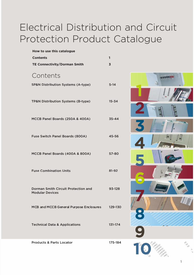
Electrical Distribution and Circuit
Protection Product Catalogue
Contents
SP&N Distribution Systems (A-type) 5-14
TP&N Distribution Systems (B-type) 15-34
MCCB Panel Boards (250A & 400A) 35-44
Fuse Switch Panel Boards (800A) 45-56
MCCB Panel Boards (400A & 800A) 57-80
Fuse Combination Units 81-92
Dorman Smith Circuit Protection and 93-128
Modular Devices
MCB and MCCB General Purpose Enclosures 129-130
Technical Data & Applications 131-174
Products & Parts Locator 175-184
How to use this catalogue
Contents 1
TE Connectivity/Dorman Smith 3
2 0
1 0 1
2 4
1 1 2
2 4
1 1 2
2 4
1 1 2
L M
L M 5 0
L M 6 0
L M 2 P
2 0
L M 3 P
1 0
L M 3 P
2 0
L M 3 P
3 0
L M 3 P
4 0
M B 2
3
1 1 0
1 1 0
1 1 0
1 1
2
123
456
9
8
10
7
7/21/2019 TE Dorman Smith Product Portofolio 2011
http://slidepdf.com/reader/full/te-dorman-smith-product-portofolio-2011 4/182
2
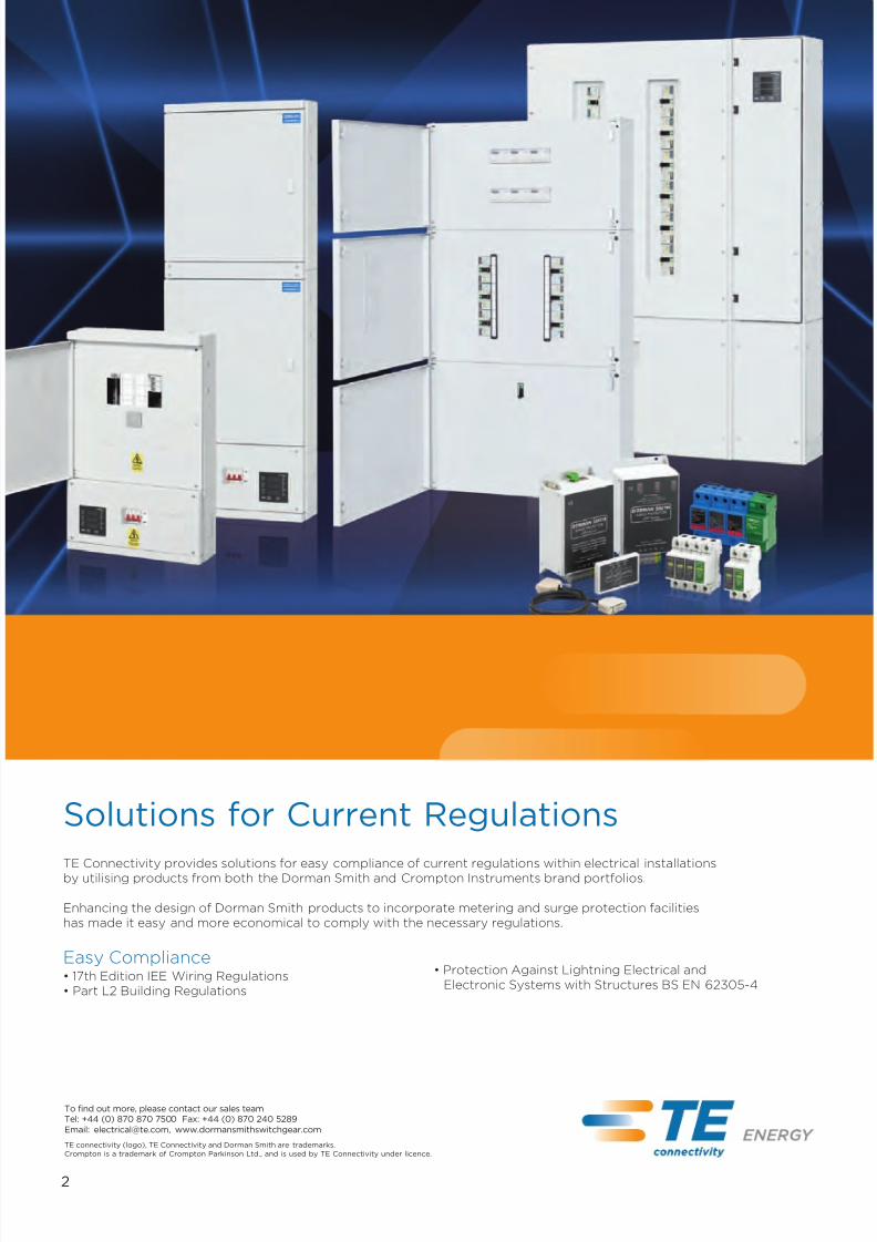
TE Connectivity provides solutions for easy compliance of current regulations within electrical installationsby utilising products from both the Dorman Smith and Crompton Instruments brand portfolios.
Enhancing the design of Dorman Smith products to incorporate metering and surge protection facilities
has made it easy and more economical to comply with the necessary regulations.
Easy Compliance• 17th Edition IEE Wiring Regulations
• Part L2 Building Regulations
• Protection Against Lightning Electrical and
Electronic Systems with Structures BS EN 62305-4
Solutions for Current Regulations
To find out more, please contact our sales team
Tel: +44 (0) 870 870 7500 Fax: +44 (0) 870 240 5289
Email: [email protected], www.dormansmithswitchgear.com
TE connectivity (logo), TE Connectivity and Dorman Smith are trademarks.
Crompton is a trademark of Crompton Parkinson Ltd., and is used by TE Connectivity under licence.
7/21/2019 TE Dorman Smith Product Portofolio 2011
http://slidepdf.com/reader/full/te-dorman-smith-product-portofolio-2011 5/182
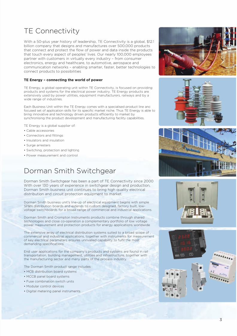
TE Connectivity
With a 50-plus year history of leadership, TE Connectivity is a global, $12.1
billion company that designs and manufactures over 500,000 products
that connect and protect the flow of power and data inside the products
that touch every aspect of peoples’ lives. Our nearly 100,000 employees
partner with customers in virtually every industry – from consumerelectronics, energy and healthcare, to automotive, aerospace and
communication networks – enabling smarter, faster, better technologies to
connect products to possibilities.
TE Energy – connecting the world of power
TE Energy, a global operating unit within TE Connectivity, is focused on providing
products and systems for the electrical power industry. TE Energy products are
extensively used by power utilities, equipment manufacturers, railways and by a
wide range of industries.
Each Business Unit within the TE Energy comes with a specialised product line and
focused set of application skills for its specific market niche. Thus TE Energy is able to
bring innovative and technology driven products efficiently to market by
synchronising the product development and manufacturing facility capabilities.
TE Energy is a global supplier of:
• Cable accessories
• Connectors and fittings
• Insulators and insulation
• Surge arresters
• Switching, protection and lighting
• Power measurement and control
Dorman Smith Switchgear
Dorman Smith Switchgear has been a part of TE Connectivity since 2000.
With over 130 years of experience in switchgear design and production,
Dorman Smith business unit continues to bring high quality electrical
distribution and circuit protection equipment to market.
Dorman Smith business unit's line-up of electrical equipment begins with simple
SP&N distribution boards and extends to custom designed, factory built, low-
voltage switchboards for a broad range of commercial and industrial applications.
Dorman Smith and Crompton Instruments products combine through shared
technologies and close co-operation a complementary portfolio of low voltage
power measurement and protection products for energy applications worldwide.
The extensive array of electrical distribution systems suited to a broad scope of ,
commercial and industrial applications, together with instruments for measurement
of key electrical parameters ensures unrivalled capability to fulfil the most
demanding specifications.
End user applications for the company’s products and systems are found in rail
transportation, building management, utilities and infrastructure, together with
the manufacturing sector and many parts of the process industry.
The Dorman Smith product range includes:
• MCB distribution board systems
• MCCB panel board systems
• Fuse combination switch units
• Modular control devices
• Digital metering panel instruments
3

7/21/2019 TE Dorman Smith Product Portofolio 2011
http://slidepdf.com/reader/full/te-dorman-smith-product-portofolio-2011 6/182
The range of Modis LV distribution switchboard systems is designed and engineered by Dorman Smith business unitand this range of fully type tested assemblies comprehensively covers all low-voltage switchboard requirements up to
3200 amps!
The Modis range of LV distribution switchboard systems is available as wall-mounted or floor standing with front or
rear access.
Assembled by our trained certified partners, the Modis range of LV distribution switchboards is more than capable of
satisfying individual customer needs, for the control and protection of the power distribution system in commercial
and industrial applications.
Dorman Smith Modis Switchboards
4
To find out more, please contact our sales team
Tel: 01772 325 380 Fax: 01772 325 385
Email: [email protected], www.dormansmithswitchgear.com
TE connectivity (logo), TE Connectivity, Dorman Smith and Modis are trademarks.

7/21/2019 TE Dorman Smith Product Portofolio 2011
http://slidepdf.com/reader/full/te-dorman-smith-product-portofolio-2011 7/182
1Section
SP&N Distribution Systems
Loadlimiter 63 Range of SP&N DistributionSystems (A-type)
7/21/2019 TE Dorman Smith Product Portofolio 2011
http://slidepdf.com/reader/full/te-dorman-smith-product-portofolio-2011 8/182
6
Key Features• Distribution board has 125A
rated busbars• Distribution boards can
be stacked
• Choice of switch disconnectoror RCCB incomer• Boards have standard height
(250mm) and depth (116mm)
Available Options• Distribution boards provide from
6 to 22 outgoing ways• Incomer can be double-pole
switch disconnector up to 125Aor double-pole RCCB up to 100A
• Outgoing ways can beconfigured with 10kA-ratedMCBs or RCBOs
• Matching service centres
equipped with 8 to 24modular ways
Additional Features• Single module shunt trip
and auxiliary contacts easilyfitted to MCBs
• Neutral and earth terminal foreach single-pole way
• IP4X Ingress Protection
ComplianceDistribution boards EN 60439-3MCBs EN 60898Contactors EN 61095
RCBOs EN 61009RCCBs EN 61008
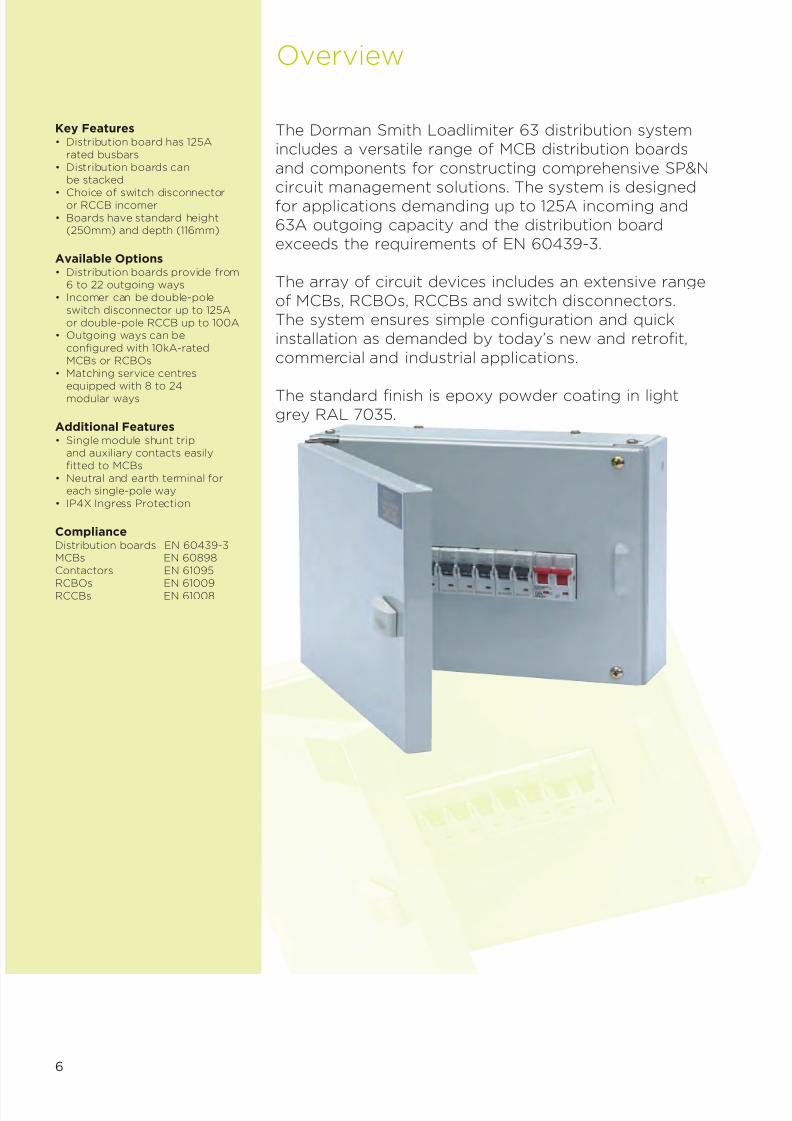
Overview
The Dorman Smith Loadlimiter 63 distribution systemincludes a versatile range of MCB distribution boards
and components for constructing comprehensive SP&Ncircuit management solutions. The system is designedfor applications demanding up to 125A incoming and63A outgoing capacity and the distribution boardexceeds the requirements of EN 60439-3.
The array of circuit devices includes an extensive rangeof MCBs, RCBOs, RCCBs and switch disconnectors.The system ensures simple configuration and quickinstallation as demanded by today’s new and retrofit,
commercial and industrial applications.
The standard finish is epoxy powder coating in lightgrey RAL 7035.

7/21/2019 TE Dorman Smith Product Portofolio 2011
http://slidepdf.com/reader/full/te-dorman-smith-product-portofolio-2011 9/182
7
SP&N Distribution System
Modular Devices
• Surge protection• Metering• Contactors• Timer• Residual current circuit breaker
A-type Distribution Boards
• Service centres• Stacking kits
Circuit Protection Devices
• Miniature circuit breakers• Residual current circuit breaker with
overcurrent protection - RCBO• Residual current circuit breakers - RCCB
Incoming Devices
• Switch disconnectors• Residual current circuit
breakers - RCCB
7/21/2019 TE Dorman Smith Product Portofolio 2011
http://slidepdf.com/reader/full/te-dorman-smith-product-portofolio-2011 10/182
8
1
3
2
4
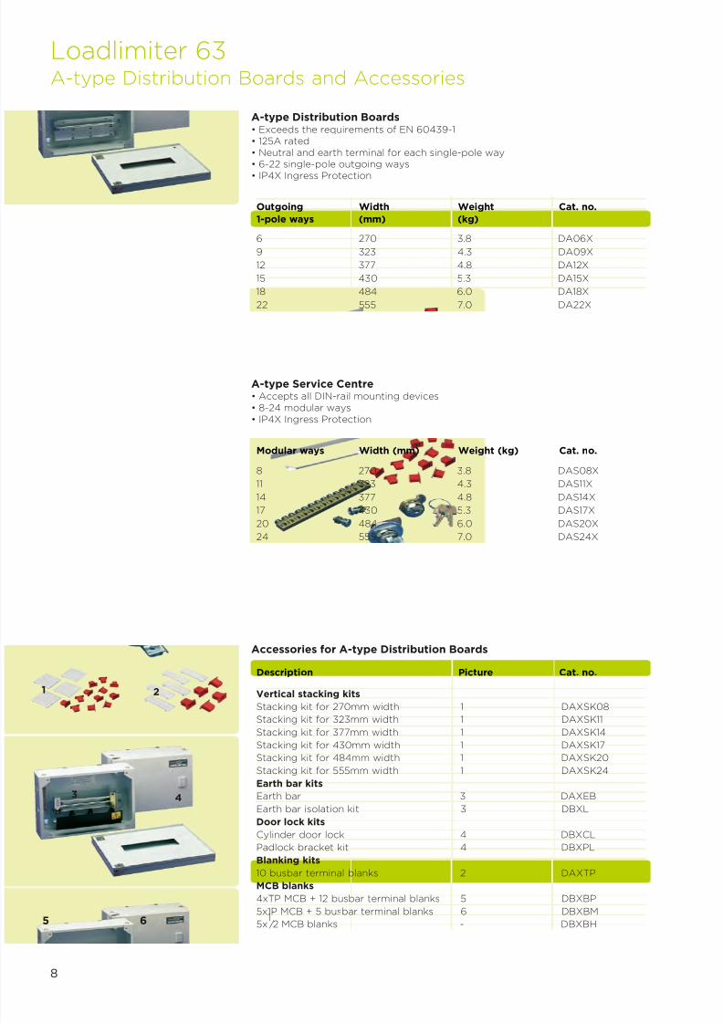
A-type Distribution Boards• Exceeds the requirements of EN 60439-1• 125A rated• Neutral and earth terminal for each single-pole way• 6-22 single-pole outgoing ways
• IP4X Ingress Protection
6 270 3.8 DA06X
9 323 4.3 DA09X
12 377 4.8 DA12X
15 430 5.3 DA15X
18 484 6.0 DA18X
22 555 7.0 DA22X
Outgoing Width Weight Cat. no.
1-pole ways (mm) (kg)
A-type Service Centre• Accepts all DIN-rail mounting devices• 8-24 modular ways• IP4X Ingress Protection
8 270 3.8 DAS08X
11 323 4.3 DAS11X
14 377 4.8 DAS14X
17 430 5.3 DAS17X
20 484 6.0 DAS20X
24 555 7.0 DAS24X
Modular ways Width (mm) Weight (kg) Cat. no.
Accessories for A-type Distribution Boards
Vertical stacking kits
Stacking kit for 270mm width 1 DAXSK08
Stacking kit for 323mm width 1 DAXSK11
Stacking kit for 377mm width 1 DAXSK14
Stacking kit for 430mm width 1 DAXSK17
Stacking kit for 484mm width 1 DAXSK20
Stacking kit for 555mm width 1 DAXSK24
Earth bar kits
Earth bar 3 DAXEB
Earth bar isolation kit 3 DBXL
Door lock kits
Cylinder door lock 4 DBXCL
Padlock bracket kit 4 DBXPL
Blanking kits
10 busbar terminal blanks 2 DAXTP
MCB blanks
4xTP MCB + 12 busbar terminal blanks 5 DBXBP
5x1P MCB + 5 busbar terminal blanks 6 DBXBM
5x1 ⁄2 MCB blanks - DBXBH
Description Picture Cat. no.
Loadlimiter 63
A-type Distribution Boards and Accessories
5 6
7/21/2019 TE Dorman Smith Product Portofolio 2011
http://slidepdf.com/reader/full/te-dorman-smith-product-portofolio-2011 11/182
9
Direct connection 35 1 DBXD0
Direct connection 70 2 DAXD1
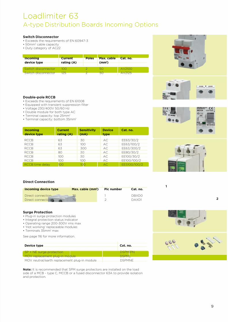
Switch Disconnector• Exceeds the requirements of EN 60947-3• 50mm2 cable capacity• Duty category of AC22
Switch disconnector 100 2 50 AV2100
Switch disconnector 125 2 50 AV2125
Incoming Current Poles Max. cable Cat. no.
device type rating (A) (mm2)
RCCB 63 30 AC EE63/30/2
RCCB 63 100 AC EE63/100/2
RCCB 63 300 AC EE63/300/2
RCCB 80 30 AC EE80/30/2
RCCB 100 30 AC EE100/30/2
RCCB 100 100 AC EE100/100/2
RCCB time delay 100 100 AC EES100/100/2
Incoming Current Sensitivity Device Cat. no.
device type rating (A) (mA) type
Double-pole RCCB• Exceeds the requirements of EN 61008• Equipped with transient suppression filter• Voltage 230/400V 50/60 Hz
• Double module for both type AC• Terminal capacity: top 25mm2
• Terminal capacity: bottom 35mm2
Direct Connection
Incoming device type Max. cable (mm2) Pic number Cat. no.
SP + NE surge protection DSPM1PN
MOV replacement plug-in module DSPML
MOV neutral/earth replacement plug-in module DSPMNE
Device type Cat. no.
Surge Protection• Plug-in surge protection modules• Integral protection status indicator
• Operating range 200-300V rms max• ‘Hot working’ replaceable modules• Terminals 35mm2 max
See page 116 for more information.
Note: It is recommended that SPM surge protectors are installed on the loadside of a MCB - type C, MCCB or a fused disconnector 63A to provide isolationand protection.
1
2
Loadlimiter 63
A-type Distribution Boards Incoming Options

7/21/2019 TE Dorman Smith Product Portofolio 2011
http://slidepdf.com/reader/full/te-dorman-smith-product-portofolio-2011 12/182
10
Single-pole MCBs• Exceeds the requirements of EN 60898• 10kA rated breaking capacity to EN 60898• 15kA rated breaking capacity to EN60947-2• Contact position indicator
• 35mm2
cable capacity
6 K1PB06 K1PC06 K1PD06
10 K1PB10 K1PC10 K1PD10
13 K1PB13 K1PC13 -
16 K1PB16 K1PC16 K1PD16
20 K1PB20 K1PC20 K1PD20
25 K1PB25 K1PC25 K1PD25
32 K1PB32 K1PC32 K1PD32
40 K1PB40 K1PC40 T1PD40*
50 K1PB50 K1PC50 T1PD50*
63 K1PB63 K1PC63 T1PD63*
Current rating (A) B type cat. no. C type cat. no. D type cat. no.
6 30 KR1PB0630 KR1PC063010 30 KR1PB1030 KR1PC1030
16 30 KR1PB1630 KR1PC1630
20 30 KR1PB2030 KR1PC2030
32 30 KR1PB3230 KR1PC3230
40 30 KR1PB4030 KR1PC4030
45 30 KR1PB4530 KR1PC4530
6 100 - KR1PC06100
10 100 - KR1PC10100
16 100 - KR1PC16100
20 100 - KR1PC20100
32 100 - KR1PC32100
40 100 - KR1PC40100
Current rating (A) Sensitivity (mA) B type cat. no. C type cat. no.
Single Module RCBOs• Exceeds the requirements of EN 61009• Single module: type AC• 10kA rated breaking capacity• Terminal capacity: top terminals 10mm2
• Terminal capacity: bottom terminals 35mm2
Double Module RCBOs• Exceeds the requirements of
EN 61009, IEC 61009• SP&SwN configuration• Rated breaking capacity up to 10kA• Contact position indicator• Rated voltage Ue ~230V• Rated frequency 50Hz
• Energy limiting class 3• Type AC• Terminal capacity: outgoing
terminals 35mm2
• Terminal capacity: busbar sideterminals 35mm2
Loadlimiter 63
A-type Outgoing Devices
6 30 KR2PB0630 KR2PC0630
10 30 KR2PB1030 KR2PC103016 30 KR2PB1630 KR2PC1630
20 30 KR2PB2030 KR2PC2030
32 30 KR2PB3230 KR2PC3230
40 30 KR2PB4030 KR2PC4030
Current rating (A) Sensitivity (mA) B type cat. no. C type cat. no.
* 6kA/10kA - EN60898/EN60947-2
7/21/2019 TE Dorman Smith Product Portofolio 2011
http://slidepdf.com/reader/full/te-dorman-smith-product-portofolio-2011 13/182
11
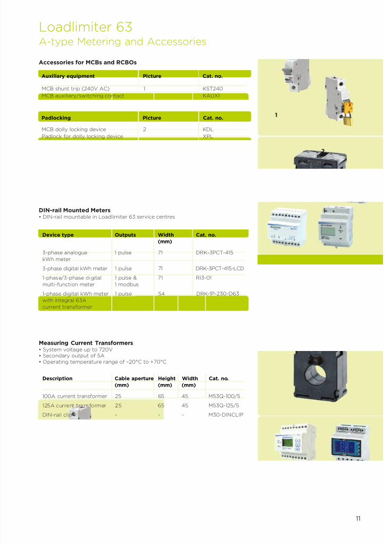
Accessories for MCBs and RCBOs
MCB shunt trip (240V AC) 1 KST240
MCB auxiliary/switching contact KAUX1
Auxiliary equipment Picture Cat. no.
MCB dolly locking device 2 KDL
Padlock for dolly locking device XPL
Padlocking Picture Cat. no.
Measuring Current Transformers• System voltage up to 720V• Secondary output of 5A• Operating temperature range of –20°C to +70°C
Description Cable aperture Height Width Cat. no.(mm) (mm) (mm)
100A current transformer 25 65 45 M53Q-100/5
125A current transformer 25 65 45 M53Q-125/5
DIN-rail clip - - - M30-DINCLIP
DIN-rail Mounted Meters• DIN-rail mountable in Loadlimiter 63 service centres
Device type Outputs Width Cat. no.
(mm)
3-phase analogue 1 pulse 71 DRK-3PCT-415
kWh meter
3-phase digital kWh meter 1 pulse 71 DRK-3PCT-415-LCD
1-phase/3-phase digital 1 pulse & 71 RI3-01
multi-function meter 1 modbus1-phase digital kWh meter 1 pulse 54 DRK-1P-230-D63
with integral 63A
current transformer
Loadlimiter 63
A-type Metering and Accessories
1
2

7/21/2019 TE Dorman Smith Product Portofolio 2011
http://slidepdf.com/reader/full/te-dorman-smith-product-portofolio-2011 14/182
12
Loadlimiter 63 Selection Chart - A-type
Distribution Boards
Busbar rating Outgoing ways Width (mm) Weight (kg) Cat. no.
Service Centres
For DIN-rail modules Modular ways
Stacking kit for 270mm width DAXSK08
Stacking kit for 323mm width DAXSK11
Stacking kit for 377mm width DAXSK14
Stacking kit for 430mm width DAXSK17
Stacking kit for 484mm width DAXSK20
Stacking kit for 555mm width DAXSK24
Blanking kits
Busbar terminal blanks (set of 10) DAXTP
Earth bar kits
Earth bar DAXEB
Earth bar isolation kit DBXL
Door lock kits
Cylinder door lock DBXCL
Padlock bracket kit DBXPL
Accessories for DA Type Distribution Boards
Vertical stacking kits
Surge Protection
125A 6 270 3.8 DA06X
125A 9 323 4.3 DA09X
125A 12 377 4.8 DA12X125A 15 430 5.3 DA15X
125A 18 484 6.0 DA18X
125A 22 555 7.0 DA22X
Service centre 8 270 3.8 DAS08X
Service centre 11 323 4.3 DAS11X
Service centre 14 377 4.8 DAS14X
Service centre 17 430 5.3 DAS17X
Service centre 20 484 6.0 DAS20X
Service centre 24 555 7.0 DAS24X
Switch disconnector 100 - 50 AV2100Switch disconnector 125 - 50 AV2125RCCB, type AC 63 30 35 EE63/30/2RCCB, type AC 63 100 35 EE63/100/2RCCB, type AC 63 300 35 EE63/300/2RCCB, type AC 80 30 35 EE80/30/2RCCB, type AC 100 30 35 EE100/30/2RCCB, type AC 100 100 35 EE100/100/2RCCB type AC time delay 100 100 35 EES100/100/2Direct connection - - 35 DBXD0Direct connection - - 70 DAXD1
Incoming Devices
Device type Current rating (A) Sensitivity (mA) Max. cable (mm2)
SP + NE surge protection DSPM1PN
MOV replacement plug-in module DSPML
MOV neutral/earth replacement plug-in module DSPMNE

7/21/2019 TE Dorman Smith Product Portofolio 2011
http://slidepdf.com/reader/full/te-dorman-smith-product-portofolio-2011 15/182
13
Loadlimiter 63 Selection Chart - A-type
1-pole 6 K1PB06 K1PC06 K1PD06
1-pole 10 K1PB10 K1PC10 K1PD10
1-pole 13 K1PB13 K1PC13 K1PD131-pole 16 K1PB16 K1PC16 K1PD16
1-pole 20 K1PB20 K1PC20 K1PD20
1-pole 25 K1PB25 K1PC25 K1PD25
1-pole 32 K1PB32 K1PC32 K1PD32
1-pole 40 K1PB40 K1PC40 T1PD40*
1-pole 50 K1PB50 K1PC50 T1PD50*
1-pole 63 K1PB63 K1PC63 T1PD63*
SP&N MCBs – B, C & D types
10kA/15kA breaking capacity Current rating (A) B type cat. no. C type cat. no. D type cat. no.
Single module, type AC 6 30 KR1PB0630 KR1PC0630
Single module, type AC 10 30 KR1PB1030 KR1PC1030
Single module, type AC 16 30 KR1PB1630 KR1PC1630
Single module, type AC 20 30 KR1PB2030 KR1PC2030
Single module, type AC 32 30 KR1PB3230 KR1PC3230
Single module, type AC 40 30 KR1PB4030 KR1PC4030
Single module, type AC 45 30 KR1PB4530 KR1PC4530
Single module, type AC 6 100 - KR1PC06100
Single module, type AC 10 100 - KR1PC10100
Single module, type AC 16 100 - KR1PC16100
Single module, type AC 20 100 - KR1PC20100
Single module, type AC 32 100 - KR1PC32100Single module, type AC 40 100 - KR1PC40100
SP&N RCBOs – B & C types
10kA breaking capacity Current rating (A) Sensitivity B type C typeDevice type (mA) cat. no. cat. no.
Accessories for MCBs and RCBOs
Description Cat. no.
3-phase analogue kWh meter 1 pulse 71 DRK-3PCT-415
3-phase digital kWh meter 1 pulse 71 DRK-3PCT-415-LCD
1-phase/3-phase digital multi-function meter 1 pulse & 1 modbus 71 RI3-01
1-phase digital kWh meter with integral 63Acurrent transformer 1 pulse 54 DRK-1P-230-D63
Current transformer, 100A - - M53Q-100/5
Current transformer, 125A - - M53Q-125/5
Metering
Description Outputs Width (mm) Cat. no.
Auxiliary equipment
MCB shunt trip (240V ac) KST240
MCB auxiliary/switching contact KAUX1
Padlocking
MCB dolly locking device KDL
Padlock for dolly locking device XPL
Blanking pieces
MCB blanks (4xTP MCB ways + 12 busbar terminal blanks) DBXBP
MCB blanks (5xSP MCB ways + 5 busbar terminal blanks) DBXBM
MCB blanks (5x1 ⁄2 MCB ways) DBXBH
6kA/10kA - EN60898/EN60947-2

7/21/2019 TE Dorman Smith Product Portofolio 2011
http://slidepdf.com/reader/full/te-dorman-smith-product-portofolio-2011 16/182
14
6 270 3.8 DA06X
9 323 4.3 DA09X
12 377 4.8 DA12X
15 430 5.3 DA15X
18 484 6.0 DA18X
22 555 7.0 DA22X
1-pole ways Width (mm) Weight (kg) Cat. no.
A-type Distribution Boards
8 270 3.8 DAS08X
11 323 4.3 DAS11X
14 377 4.8 DAS14X
17 430 5.3 DAS17X
20 484 6.0 DAS20X
24 555 7.0 DAS24X
Modular ways Width (mm) Weight (kg) Cat. no.
A-type Service Centres
All dimensions in mm
Loadlimiter 63Outline Drawings and Dimensions

7/21/2019 TE Dorman Smith Product Portofolio 2011
http://slidepdf.com/reader/full/te-dorman-smith-product-portofolio-2011 17/182
2Section
TP&N Distribution Systems
Loadlimiter 63 Range of TP&N DistributionSystems (B-type)
7/21/2019 TE Dorman Smith Product Portofolio 2011
http://slidepdf.com/reader/full/te-dorman-smith-product-portofolio-2011 18/182
16
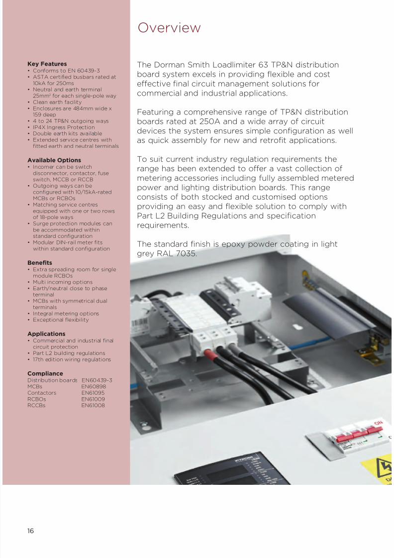
Key Features• Conforms to EN 60439-3• ASTA certified busbars rated at
10kA for 250ms• Neutral and earth terminal
25mm2
for each single-pole way• Clean earth facility• Enclosures are 484mm wide x
159 deep• 4 to 24 TP&N outgoing ways• IP4X Ingress Protection• Double earth kits available• Extended service centres with
fitted earth and neutral terminals
Available Options• Incomer can be switch
disconnector, contactor, fuseswitch, MCCB or RCCB
• Outgoing ways can be
configured with 10/15kA-ratedMCBs or RCBOs• Matching service centres
equipped with one or two rowsof 18-pole ways
• Surge protection modules canbe accommodated withinstandard configuration
• Modular DIN-rail meter fitswithin standard configuration
Benefits• Extra spreading room for single
module RCBOs• Multi incoming options• Earth/neutral close to phase
terminal• MCBs with symmetrical dual
terminals• Integral metering options• Exceptional flexibility
Applications• Commercial and industrial final
circuit protection• Part L2 building regulations• 17th edition wiring regulations
ComplianceDistribution boards EN60439-3MCBs EN60898Contactors EN61095RCBOs EN61009RCCBs EN61008
Overview
The Dorman Smith Loadlimiter 63 TP&N distributionboard system excels in providing flexible and cost
effective final circuit management solutions forcommercial and industrial applications.
Featuring a comprehensive range of TP&N distributionboards rated at 250A and a wide array of circuitdevices the system ensures simple configuration as wellas quick assembly for new and retrofit applications.
To suit current industry regulation requirements therange has been extended to offer a vast collection of
metering accessories including fully assembled meteredpower and lighting distribution boards. This range
consists of both stocked and customised optionsproviding an easy and flexible solution to comply withPart L2 Building Regulations and specificationrequirements.
The standard finish is epoxy powder coating in lightgrey RAL 7035.

7/21/2019 TE Dorman Smith Product Portofolio 2011
http://slidepdf.com/reader/full/te-dorman-smith-product-portofolio-2011 19/182
17
TP&N Distribution System
Modular Devices
• Surge protection• Meters, current transformers and
wiring looms• Contactors• Timer• Residual current circuit breaker
B-type Distribution Boards
• Service centres• Stacking kits• Assembled metered boards• Metering enclosures
Circuit Protection Devices
• Miniature circuit breakers• Residual current circuit breaker with
overcurrent protection - RCBO• Residual current circuit breaker - RCCB
Incoming Devices
• Switch disconnectors - modular 125A max• Switch disconnectors - MCCB 250A max• Residual current circuit breakers - RCCB• Fuse switch• Moulded case circuit breakers• Contactors
7/21/2019 TE Dorman Smith Product Portofolio 2011
http://slidepdf.com/reader/full/te-dorman-smith-product-portofolio-2011 20/182
18
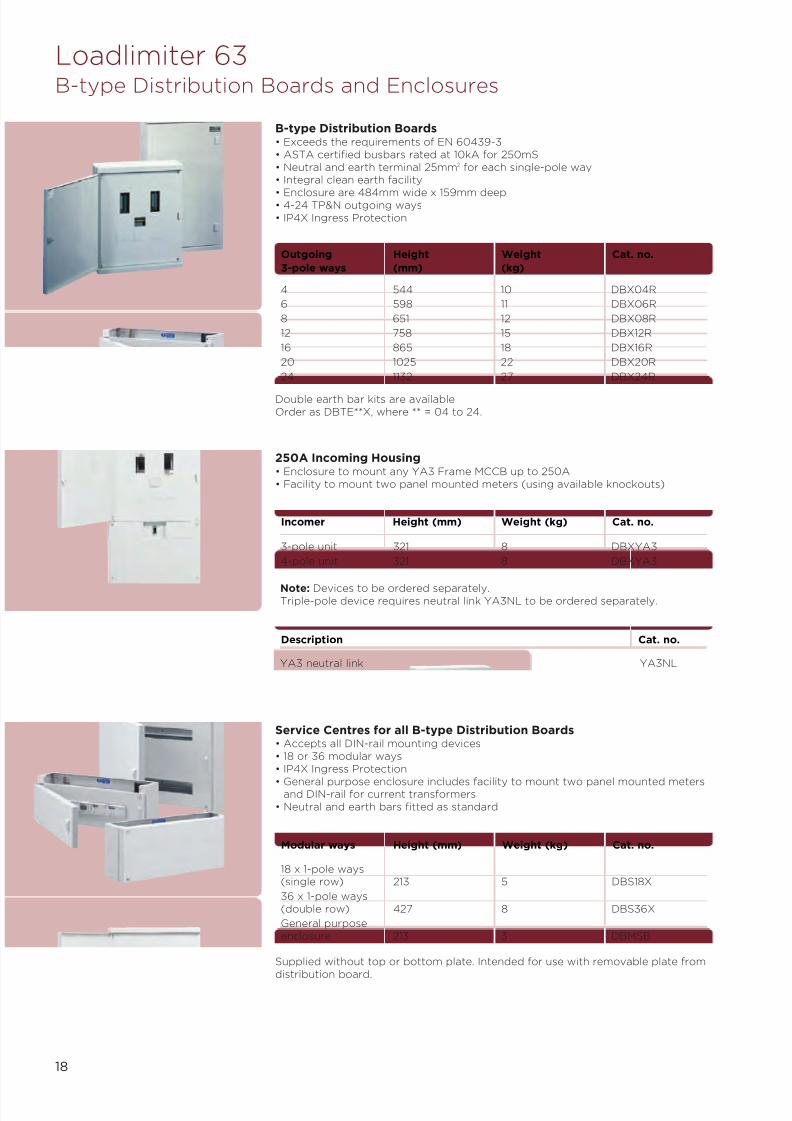
B-type Distribution Boards• Exceeds the requirements of EN 60439-3• ASTA certified busbars rated at 10kA for 250mS• Neutral and earth terminal 25mm2 for each single-pole way• Integral clean earth facility
• Enclosure are 484mm wide x 159mm deep• 4-24 TP&N outgoing ways• IP4X Ingress Protection
4 544 10 DBX04R
6 598 11 DBX06R
8 651 12 DBX08R
12 758 15 DBX12R
16 865 18 DBX16R
20 1025 22 DBX20R
24 1132 27 DBX24R
Outgoing Height Weight Cat. no.
3-pole ways (mm) (kg)
250A Incoming Housing• Enclosure to mount any YA3 Frame MCCB up to 250A• Facility to mount two panel mounted meters (using available knockouts)
3-pole unit 321 8 DBXYA3
4-pole unit 321 8 DBXYA3
Incomer Height (mm) Weight (kg) Cat. no.
Service Centres for all B-type Distribution Boards• Accepts all DIN-rail mounting devices• 18 or 36 modular ways• IP4X Ingress Protection
• General purpose enclosure includes facility to mount two panel mounted metersand DIN-rail for current transformers
• Neutral and earth bars fitted as standard
Double earth bar kits are availableOrder as DBTE**X, where ** = 04 to 24.
Note: Devices to be ordered separately.Triple-pole device requires neutral link YA3NL to be ordered separately.
18 x 1-pole ways(single row) 213 5 DBS18X
36 x 1-pole ways(double row) 427 8 DBS36X
General purposeenclosure 213 3 DBMSB
Modular ways Height (mm) Weight (kg) Cat. no.
Supplied without top or bottom plate. Intended for use with removable plate from
distribution board.
Description Cat. no.
YA3 neutral link YA3NL
Loadlimiter 63B-type Distribution Boards and Enclosures

7/21/2019 TE Dorman Smith Product Portofolio 2011
http://slidepdf.com/reader/full/te-dorman-smith-product-portofolio-2011 21/182
19
Conversion kits plus spares
TP&N to SP&N conversion kit 1 DBXTS
Spare end plate 2 DBXEP
Fixing kit for 24 way distribution boards DBX24FK
Blank way label for 24 way distribution boards DBX24WL
DA18X to B type board stacking kit DBXSKA
Blanking pieces
MCB blanks (4xTP MCB ways + 12 busbar terminal blanks) 8 DBXBP
MCB blanks (5x1P MCB ways + 5 busbar terminal blanks) 9 DBXBM
MCB blanks (5x1 ⁄ 2 MCB Ways) DBXBH
Joining kit
Kit for vertically joining two distribution boards 3 DBXJK
Terminal bars
Terminal bar for 6 ways (6 useable 1P ways) 6 DBXT06
Terminal bar for 12 ways (12 useable 1P ways) 6 DBXT12
Terminal bar for 18 ways (18 useable 1P ways) 6 DBXT18
Terminal bar for 24 ways (24 useable 1P ways) 6 DBXT24Blanking kits
Busbar terminal blanks (set of 10) 4 DAXTP
Earth bar kits
Earth bar 7 DAXEB
Earth bar isolation kit 5 DBXL
Double earth bar facility
Earth bar kit with terminal for each outgoing way(where ** = 04, 06, 08, 12, 16, 20 or 24 ways) DBTE**X
Door lock kits
Cylinder door lock 10 DBXCL
Padlock bracket kit 11 DBXPL
Description Picture Cat. no.
1 2
3
4
5 6
7
Loadlimiter 63B-type Distribution Boards Accessories
8
11
10
9

7/21/2019 TE Dorman Smith Product Portofolio 2011
http://slidepdf.com/reader/full/te-dorman-smith-product-portofolio-2011 22/182
Switch disconnector
Device type Max. cable Sensitivity Incoming Connection(mm2) (mA) device cat. no. kit cat. no.
100A, 3-pole 50 - AV3100 N/A
100A, 4-pole 50 - AV4100 DBXCKR
125A, 3-pole 50 - AV3125 N/A
125A, 4-pole 50 - AV4125 DBXCKR
4-pole RCCB Cat. no.
40A, type AC 35 30 EE40/30/4 DBXCKR
40A, type AC 35 30 EE40/100/4 DBXCKR
63A, type AC 35 30 EE63/30/4 DBXCKR
63A, type AC 35 100 EE63/100/4 DBXCKR
63A, type AC 35 300 EE63/300/4 DBXCKR
100A, type AC 35 30 EE100/30/4 DBXCKR
100A, type AC 35 100 EE100/100/4 DBXCKR
100A, type AC 35 300 EE100/300/4 DBXCKR
100A, type AC, 35 100 EES100/100/4 DBXCKRtime delay
Contactor Cat. no.
40A, 4-pole - - EE4P40CO DBXCKR
63A, 4-pole - - EE4P63CO DBXCKR
Fuse switch Cat. no.
100A, 3-pole 70 - HBF3P100N DBXLSA1
200A, 3-pole 150 - HBF3P200N DBXLSA2
Switch Disconnector 125A Max• Exceeds the requirements of EN 60947-3• 50mm2 cable capacity• Duty category of AC22
RCCBs• Exceeds the requirements of EN 61008• Double width module, 35mm• Type AC• Terminal capacity: 40A-63A: 25mm2
• Terminal capacity: 100A: 35mm2
Contactors – DIN-rail Mounted• Exceeds the requirements of EN 61095• May require de-rating when used with inductive loads – see Contactor De-rating
table in the Technical Applications section
Loadlimiter 63B-type Incoming Options
20
Fuse Combination Units

7/21/2019 TE Dorman Smith Product Portofolio 2011
http://slidepdf.com/reader/full/te-dorman-smith-product-portofolio-2011 23/182
21
Surge Protection
Device type Width (mm) Cat. no.
3-phase with neutral/earth surge protection module 54 DSPM3PN
MOV replacement plug-in SPM 17.5 DSPML
MOV neutral/earth replacement plug-in SPM 17.5 DSPMNE
• Plug-in surge protection modules• Integral protection status indicator• Thermal and current overload fusing• Three-phase operating range, 380-515V rms max
• ‘Hot working’ replaceable modules
Note: Connection kit DBXCKR must be ordered to provide the additional DIN-railneeded to mount this device in the distribution enclosure below the incomingdevice (for 125A max only). For 250A applications devices should be mounted in aservice centre.
Device type Max. cable Icu Incoming device
(mm2) cat. no.
63A, 3-pole 150* 25kA YA3N3P63T
63A, 4-pole 150* 25kA YA3N4P63T
100A, 3-pole 150* 25kA YA3N3P100T
100A, 4-pole 150* 25kA YA3N4P100T
125A, 3-pole 150* 25kA YA3N3P125T
125A, 4-pole 150* 25kA YA3N4P125T
160A, 3-pole 150* 25kA YA3N3P160T
160A, 4-pole 150* 25kA YA3N4P160T
200A, 3-pole 150* 25kA YA3N3P200T
200A, 4-pole 150* 25kA YA3N4P200T
250A, 3-pole 150* 25kA YA3N3P250T
250A, 4-pole 150* 25kA YA3N4P250T
250A, 3-pole 150* - YA3B3P250Dswitch disconnector
250A, 4-pole 150* - YA3B4P250Dswitch disconnector
YA3 frame MCCB - 250A Max• Standard cable termination 95mm2
• Cable clamps termination - 120mm2
• Maximum cable termination is 150mm2 using reduced palm width M8 cable lugs• MCCBs have thermal and magnetic overloads except switch disconnector
• To be mounted in incoming housing (DBXYA3)
Loadlimiter 63B-type Incoming Options and Surge Protection
Direct Connection Terminal Kits
Terminals 35 1 DBXD0
Terminals 70 2 DBXD1
Terminals 150 3 DBXD2
Description Max. cable (mm2) Picture Cat. no.
1
2
3
* 150mm2 based on using reduced palm width cable lugs
7/21/2019 TE Dorman Smith Product Portofolio 2011
http://slidepdf.com/reader/full/te-dorman-smith-product-portofolio-2011 24/182
22
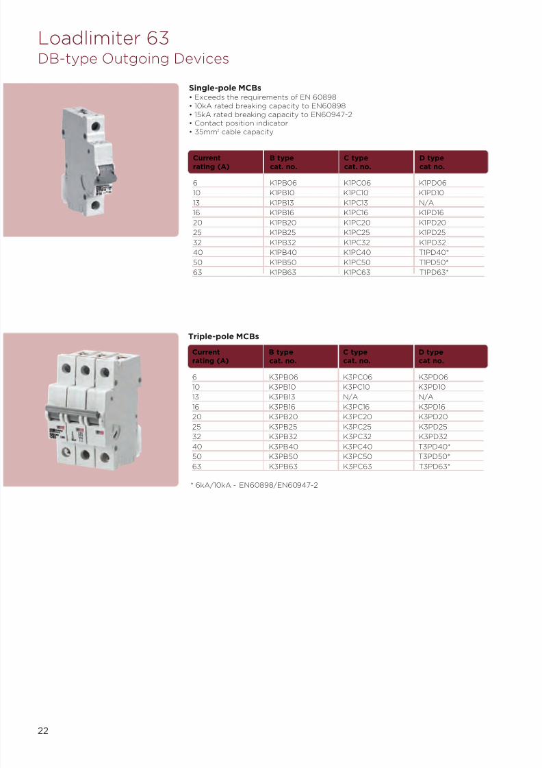
Loadlimiter 63DB-type Outgoing Devices
Current B type C type D typerating (A) cat. no. cat. no. cat no.
6 K1PB06 K1PC06 K1PD06
10 K1PB10 K1PC10 K1PD10
13 K1PB13 K1PC13 N/A
16 K1PB16 K1PC16 K1PD16
20 K1PB20 K1PC20 K1PD20
25 K1PB25 K1PC25 K1PD25
32 K1PB32 K1PC32 K1PD32
40 K1PB40 K1PC40 T1PD40*
50 K1PB50 K1PC50 T1PD50*
63 K1PB63 K1PC63 T1PD63*
Single-pole MCBs• Exceeds the requirements of EN 60898• 10kA rated breaking capacity to EN60898• 15kA rated breaking capacity to EN60947-2• Contact position indicator
• 35mm2
cable capacity
Current B type C type D typerating (A) cat. no. cat. no. cat no.
6 K3PB06 K3PC06 K3PD06
10 K3PB10 K3PC10 K3PD10
13 K3PB13 N/A N/A
16 K3PB16 K3PC16 K3PD16
20 K3PB20 K3PC20 K3PD20
25 K3PB25 K3PC25 K3PD25
32 K3PB32 K3PC32 K3PD32
40 K3PB40 K3PC40 T3PD40*
50 K3PB50 K3PC50 T3PD50*
63 K3PB63 K3PC63 T3PD63*
Triple-pole MCBs
* 6kA/10kA - EN60898/EN60947-2

7/21/2019 TE Dorman Smith Product Portofolio 2011
http://slidepdf.com/reader/full/te-dorman-smith-product-portofolio-2011 25/182
23
Current Sensitivity B type C typerating (A) (mA) cat. no. cat no.
6 30 KR1PB0630 KR1PC0630
10 30 KR1PB1030 KR1PC1030
16 30 KR1PB1630 KR1PC1630
20 30 KR1PB2030 KR1PC2030
32 30 KR1PB3230 KR1PC3230
40 30 KR1PB4030 KR1PC4030
45 30 KR1PB4530 KR1PC4530
6 100 - KR1PC06100
10 100 - KR1PC10100
16 100 - KR1PC16100
20 100 - KR1PC20100
32 100 - KR1PC32100
40 100 - KR1PC40100
Single Module RCBOs• Exceeds the requirements of EN 61009• Single module: Type AC• 10kA rated breaking capacity• Terminal capacity: outgoing terminals 10mm2
• Terminal capacity: busbar side terminals 35mm2
Loadlimiter 63B-type Outgoing Devices and Accessories
Double Module RCBOs• Exceeds the requirements of
EN 61009, IEC 61009• SP&SwN configuration• Rated breaking capacity up to 10kA• Contact position indicator• Rated voltage Ue ~230V• Rated frequency 50Hz
• Energy limiting class 3• Type AC• Terminal capacity: outgoing
terminals 35mm2
• Terminal capacity: busbar sideterminals 35mm2
Current rating (A) Sensitivity (mA) B type cat. no. C type cat. no.
6 30 KR2PB0630 KR2PC0630
10 30 KR2PB1030 KR2PC1030
16 30 KR2PB1630 KR2PC1630
20 30 KR2PB2030 KR2PC2030
32 30 KR2PB3230 KR2PC3230
40 30 KR2PB4030 KR2PC4030
1
2
Accessories for MCBs and RCBOs
Auxiliary equipment Picture Cat. no.
MCB shunt trip (240V AC) 1 KST240
MCB auxiliary/switch contact KAUX1
Padlocking Picture Cat. no.
MCB dolly locking device 2 KDL
Padlock for dolly locking device XPL
7/21/2019 TE Dorman Smith Product Portofolio 2011
http://slidepdf.com/reader/full/te-dorman-smith-product-portofolio-2011 26/182
24
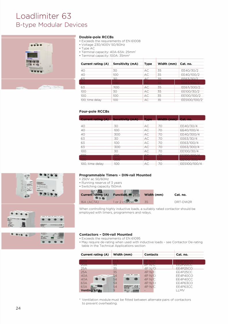
16A (AC7A) 1 or 2 channel 35 DRT-DW2R
Current rating (A) Function Width (mm) Cat. no.
Programmable Timers – DIN-rail Mounted• 250V ac 50/60Hz• Running reserve of 3 years• Switching capacity 150mA
When controlling highly inductive loads, a suitably rated contactor should beemployed with timers, programmers and relays.
Contactors – DIN-rail Mounted• Exceeds the requirements of EN 61095• May require de-rating when used with inductive loads – see Contactor De-rating
table in the Technical Applications section
Loadlimiter 63B-type Modular Devices
Double-pole RCCBs• Exceeds the requirements of EN 61008• Voltage 230/400V 50/60Hz• Type AC• Terminal capacity: 40A-63A: 25mm2
• Terminal capacity: 100A: 35mm2
Four-pole RCCBs
40 30 AC 70 EE40/30/4
40 100 AC 70 EE40/100/4
40 300 AC 70 EE40/300/4
63 30 AC 70 EE63/30/4
63 100 AC 70 EE63/100/4
63 300 AC 70 EE63/300/4
100 30 AC 70 EE100/30/4
100 100 AC 70 EE100/100/4
100 300 AC 70 EE100/300/4
100, time delay 100 AC 70 EES100/100/4
Current rating (A) Sensitivity (mA) Type Width (mm) Cat. no.
40 30 AC 35 EE40/30/2
40 100 AC 35 EE40/100/2
63 30 AC 35 EE63/30/2
63 100 AC 35 EE63/100/2
63 300 AC 35 EE63/300/2
100 30 AC 35 EE100/30/2
100 100 AC 35 EE100/100/2
100, time delay 100 AC 35 EES100/100/2
Current rating (A) Sensitivity (mA) Type Width (mm) Cat. no.
20A 17.5 2P N/O EE2P20CO20A 35 2P N/C EE2P20CC25A 35 4P N/O EE4P25CO25A 35 4P N/C EE4P25CC40A 54 4P N/O EE4P40CO40A 54 4P N/C EE4P40CC
63A 54 4P N/O EE4P63CO63A 54 4P N/C EE4P63CCVenting kit * 9 - LLMV
Current rating (A) Width (mm) Contacts Cat. no.
* Ventilation module must be fitted between alternate pairs of contactorsto prevent overheating.
7/21/2019 TE Dorman Smith Product Portofolio 2011
http://slidepdf.com/reader/full/te-dorman-smith-product-portofolio-2011 27/182
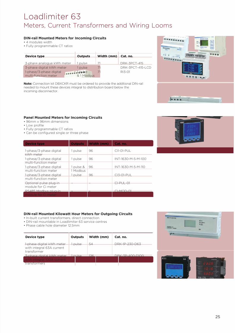
Loadlimiter 63Meters, Current Transformers and Wiring Looms
DIN-rail Mounted Meters for Incoming Circuits• 4 modules width• Fully programmable CT ratios
Note: Connection kit DBXCKR must be ordered to provide the additional DIN-railneeded to mount these devices integral to distribution board below theincoming disconnector.
Panel Mounted Meters for Incoming Circuits• 96mm x 96mm dimensions• Low profile• Fully programmable CT ratios• Can be configured single or three phase
3-phase analogue kWh meter 1 pulse 71 DRK-3PCT-415
3-phase digital kWh meter 1 pulse 71 DRK-3PCT-415-LCD
1-phase/3-phase digital 1 pulse 71 RI3-01multi-function meter & 1 Modbus
Device type Outputs Width (mm) Cat. no.
DIN-rail Mounted Kilowatt Hour Meters for Outgoing Circuits• In-built current transformers, direct connection• DIN-rail mountable in Loadlimiter 63 service centres• Phase cable hole diameter 12.5mm
25
1-phase/3-phase digital 1 pulse 96 CI1-01-PULkWh meter
1-phase/3-phase digital 1 pulse 96 INT-1630-M-5-M-100multi-function meter
1-phase/3-phase digital 1 pulse & 96 INT-1630-M-5-M-110multi-function meter 1 Modbus
1-phase/3-phase digital 1 pulse 96 CI3-01-PULmulti-function meter
Optional pulse plug-in – – CI-PUL-01module for Ci meter
RS485 Modbus plug-in – – CI-MOD-01module for Ci meter
Device type Outputs Width (mm) Cat. no.
1-phase digital kWh meter 1 pulse 54 DRK-1P-230-D63with integral 63A currenttransformer
3-phase digital kWh meter 1 pulse 126 DRK-3P-400-D100with integral 100A currenttransformers
Device type Outputs Width (mm) Cat. no.

7/21/2019 TE Dorman Smith Product Portofolio 2011
http://slidepdf.com/reader/full/te-dorman-smith-product-portofolio-2011 28/182
26
Measuring Current Transformers• Up to Class 0.5 accuracy• System voltage up to 720V• Secondary output of 5A• Operating temperature range of –20°C to +70°C
Wiring Looms for TP&N Applications(refer to page 33 for application details)• 1A fuse (rated 400V) metering harness• Current transformer harness
Wiring loom DBX04R – DBX16R Any Crompton DBXW16for single meter Instruments meter
Wiring loom DBX20R – DBX24R Any Crompton DBXW24for single meter Instruments meter
Wiring loom for DBX04R – DBX16R Any Crompton DBXW16Tsingle meter for Instruments metertop distributionboard (verticalstacking)
Description For use with Suitable meter Cat. no.
distribution boards
Power Loom for Sub-Metered Distribution Boards(refer to page 33 for application details)
• 125A and 250A power loom for joining two distribution boards
Power loom for sub metered 125A max DBXWP125distribution board
Power loom for sub metered 250A max DBXWP250distribution board
Description Current rating Cat. no.
Note: Meters, current transformers and enclosure to be ordered separately.
* 95mm2 using standard cable lugs
**150mm2 using reduced palm width lugs
100A 3-in-1 CT case size 35mm 95*/150** M3N1-35-100/5
125A 3-in-1 CT case size 35mm 95*/150** M3N1-35-125/5
200A 3-in-1 CT case size 35mm 95*/150** M3N1-35-200/5
250A 3-in-1 CT case size 35mm 95*/150** M3N1-35-250/5
Meter spreader box - DBMSB
Description Max Cable mm2 Cat. no.
Loadlimiter 63Meters, Current Transformers and Wiring Looms

7/21/2019 TE Dorman Smith Product Portofolio 2011
http://slidepdf.com/reader/full/te-dorman-smith-product-portofolio-2011 29/182
Loadlimiter 63B-type Assembled Boards Range
125A - Horizontal Arrangement with Two Multi-function Meters
• Two 125A switch disconnectors fitted:One for isolation of whole arrangementOne for isolation of lighting circuits only
• Two meter displays for separate readings of power and lighting consumption
• All power and control wiring fully tested and fitted
• Multi-function meter with pulse output for connection to a compatible BMS system
6 6 811 x 968 x 160 DBXC06NAH06CA
12 12 971 x 968 x 160 DBXC12NAH12CA
No. of power No. of TP Dimensions Cat. no.TP ways lighting ways H x W x D
125A - Vertical Arrangement with One Multi-function Meter (Lighting Only)
• Two 125A switch disconnectors fitted:One for Isolation of whole arrangementOne for isolation of lighting circuits only
• One meter display for readings of lighting consumption only
• All power and control wiring fully tested and fitted• Multi-function meter with pulse output for connection to a compatible BMS system
8 6 1452 x 484 x 160 DBXC08NNV06CA
12 8 1612 x 484 x 160 DBXC12NNV08CA
No. of power No. of TP Dimensions Cat. no.TP ways lighting ways H x W x D
8 8 972 x 968 x 160 DBXE08NAH08NA
No. of power No. of TP Dimensions Cat. no.TP ways lighting ways H x W x D
125A - Vertical Arrangement with Two Meters (kWh or Multi-function)
• Two 125A switch disconnectors fitted:One for Isolation of whole arrangementOne for isolation of lighting circuits only
• Two meter displays for separate readings of power and lighting consumption
• All power and control wiring fully tested and fitted
• Both meters have a pulse output for connection to a compatible BMS system
Multi-function 6 4 1345 x 484 x 160 DBXC06NAV04CA
Multi-function 8 6 1452 x 484 x 160 DBXC08NAV06CA
Multi-function 12 8 1612 x 484 x 160 DBXC12NAV08CA
kWh 8 6 1452 x 484 x 160 DBXC08NJV06CJ
kWh 12 8 1612 x 484 x 160 DBXC12NJV08CJ
Meter No of power No of TP Dimensions Cat. no.type TP ways lighting ways H x W x D
250A - Vertical Arrangement with Two Meters (kWh or Multi-function)
• One 250A switch disconnector fitted providing isolation for whole arrangement
• Two meter displays for separate readings of power and lighting consumption
• All power and control wiring fully tested and fitted• Both kWh and multi-function meters have a pulse output for connection to a
compatible BMS system
Multi-function 8 6 1570 x 484 x 160 DBXE08NAV06NA
Multi-function 12 8 1730 x 484 x 160 DBXE12NAV08NA
kWh 8 6 1570 x 484 x 160 DBXE08NJV06NJ
kWh 12 8 1730 x 484 x 160 DBXE12NJV08NJ
Meter No. of power No. of TP Dimensions Cat. no.type TP ways lighting ways H x W x D
250A - Horizontal Arrangement with Two Multi-function Meters
• One 250A switch disconnector fitted providing isolation for whole arrangement
• Two meter displays for separate readings of power and lighting consumption
• All power and control wiring fully tested and fitted
• Both kWh and multi-function meters have a pulse output for connection to acompatible BMS system
Customised assembled boards available

7/21/2019 TE Dorman Smith Product Portofolio 2011
http://slidepdf.com/reader/full/te-dorman-smith-product-portofolio-2011 30/182
28
18 x 1-pole ways (single row) 213 5 DBS18X
36 x 1-pole ways (double row) 427 8 DBS36XCable spreader box 213 3 DBMSB
B-type Service Centres
For use with DIN-rail modules Height (mm) Weight (kg) Cat. no.
3-pole housing 321 8 DBXYA34-pole housing 321 8 DBXYA3
B-type Incoming YA3 MCCB Enclosure
Height (mm) Weight (kg) Cat. no.
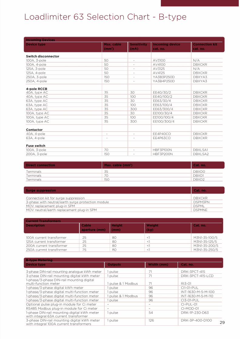
Loadlimiter 63 Selection Chart - B-type
250A 4 544 10 DBX04R
250A 6 598 11 DBX06R
250A 8 651 12 DBX08R250A 12 758 15 DBX12R250A 16 865 18 DBX16R250A 20 1025 22 DBX20R250A 24 1132 27 DBX24R
B-type Distribution Boards (without incoming device)
Busbar rating TP outgoing ways Height (mm) Weight (kg) Cat. no.
Accessories for all B-type Distribution Boards
Description Cat. no.
Conversion kits plus spares
TP&N to SP&N conversion kit DBXTS
Spare end plate DBXEP
RCCB, Contactor, 4-pole switch disconnector connection kit DBXCKR
Fixing kit for 24 way distribution boards DBX24FK
Blank way label for 24 way distribution boards DBX24WL
Blanking pieces
MCB blanks (4xTP MCB ways + 12 busbar terminal blanks) DBXBP
MCB blanks (5xSP MCB ways + 5 busbar terminal blanks) DBXBM
MCB blanks (5x1 ⁄ 2 MCB Ways) DBXBH
Joining kit
Mechanical joining kit (For joining two distribution boards vertically) DBXJK
Terminal bars
Terminal bar for 6 ways DBXT06
Terminal bar for 12 ways DBXT12
Terminal bar for 18 ways DBXT18
Terminal bar for 24 ways DBXT24
Blanking kits
Busbar terminal blanks (set of 10) DAXTP
Earth bar kits
Earth bar DAXEB
Earth bar isolation kit DBXL
Double earth bar facility
Earth bar kit with terminal for each outgoing way(where ** = 04, 06, 08, 12, 16, 20 or 24 ways) DBTE**X
Door lock kits
Cylinder door lock DBXCL
Padlock bracket kit DBXPL
125 6/6 811 968 Horizontal 2 x MF DBXC06NAH06CA
125 12/12 971 968 Horizontal 2 x MF DBXC12NAH12CA125 8/6 1452 484 Vertical 1 x MF DBXC08NNV06CA125 12/8 1612 484 Vertical 1 x MF DBXC12NNV08CA125 6/4 1345 484 Vertical 2 x MF DBXC06NAV04CA125 8/6 1452 484 Vertical 2 x MF DBXC08NAV06CA
125 12/8 1612 484 Vertical 2 x MF DBXC12NAV08CA125 8/6 1452 484 Vertical 2 x kWh DBXC08NJV06CJ125 12/8 1612 484 Vertical 2 x kWh DBXC12NJV08CJ
250 8/6 1570 484 Vertical 2 x MF DBXE08NAV06NA250 12/8 1730 484 Vertical 2 x MF DBXE12NAV08NA
250 8/6 1570 484 Vertical 2 x MF DBXE08NJV06NJ250 12/8 1730 484 Vertical 2 x MF DBXE12NJV08NJ250 8/8 972 968 Horizontal 15 x MF DBXE08NAH08NA
B-type Distribution Boards (complete with incoming device/s)
Busbar rating TP outgoing ways Height (mm) Width (mm) Arrangement Meters Cat. no.
7/21/2019 TE Dorman Smith Product Portofolio 2011
http://slidepdf.com/reader/full/te-dorman-smith-product-portofolio-2011 31/182
29
Connection kit for surge suppression DBXCKR
3-phase with neutral/earth surge protection module DSPM3PN
MOV replacement plug-in SPM DSPML
MOV neutral/earth replacement plug-in SPM DSPMNE
Surge suppression Cat. no.
Loadlimiter 63 Selection Chart - B-type
Terminals 35 DBXD0
Terminals 70 DBXD1
Terminals 150 DBXD2
Direct connection Max. cable (mm2) Cat. no.
Incoming Devices
Device type Max. cable Sensitivity Incoming device Connection kit
(mm2) (mA) cat. no. cat. no.
Switch disconnector
100A, 3-pole 50 - AV3100 N/A
100A, 4-pole 50 - AV4100 DBXCKR
125A, 3-pole 50 - AV3125 N/A
125A, 4-pole 50 - AV4125 DBXCKR
250A, 3-pole 150 - YA3B3P250D DBXYA3
250A, 4-pole 150 - YA3B4P250D DBXYA3
4-pole RCCB40A, type AC 35 30 EE40/30/2 DBXCKR
40A, type AC 35 100 EE40/100/2 DBXCKR
63A, type AC 35 30 EE63/30/4 DBXCKR
63A, type AC 35 100 EE63/100/4 DBXCKR
63A, type AC 35 300 EE63/300/4 DBXCKR
100A, type AC 35 30 EE100/30/4 DBXCKR
100A, type AC 35 100 EE100/100/4 DBXCKR100A, type AC 35 300 EE100/300/4 DBXCKR
Contactor
40A, 4-pole - - EE4P40CO DBXCKR
63A, 4-pole - - EE4P63CO DBXCKR
Fuse switch
100A, 3-pole 70 - HBF3P100N DBXLSA1
200A, 3-pole 150 - HBF3P200N DBXLSA2
100A current transformer 25 80 <1 M3N1-35-100/5125A current transformer 25 80 <1 M3N1-35-125/5
200A current transformer 25 80 <1 M3N1-35-200/5
250A current transformer 25 80 <1 M3N1-35-250/5
Current Transformers
Description Cable Height Weight Cat. no.
aperture (mm) (mm) (kg)
B-type Metering
Device type Outputs Width (mm) Cat. no.
3-phase DIN-rail mounting analogue kWh meter 1 pulse 71 DRK-3PCT-415
3-phase DIN-rail mounting digital kWh meter 1 pulse 71 DRK-3PCT-415-LCD
1-phase/3-phase DIN-rail mounting digitalmulti-function meter 1 pulse & 1 Modbus 71 RI3-01
1-phase/3-phase digital kWh meter 1 pulse 96 CI1-01-PUL
1-phase/3-phase digital multi-function meter 1 pulse 96 INT-1630-M-5-M-100
1-phase/3-phase digital multi-function meter 1 pulse & 1 Modbus 96 INT-1630-M-5-M-1101-phase/3-phase digital multi-function meter 1 pulse 96 CI3-01-PUL
Optional pulse plug-in module for Ci meter – – CI-PUL-01
RS485 Modbus plug-in module for Ci meter – – CI-MOD-01
1-phase DIN-rail mounting digital kWh meter 1 pulse 54 DRK-1P-230-D63with integral 63A current transformer
3-phase DIN-rail mounting digital kWh meter 1 pulse 126 DRK-3P-400-D100with integral 100A current transformers
7/21/2019 TE Dorman Smith Product Portofolio 2011
http://slidepdf.com/reader/full/te-dorman-smith-product-portofolio-2011 32/182
30
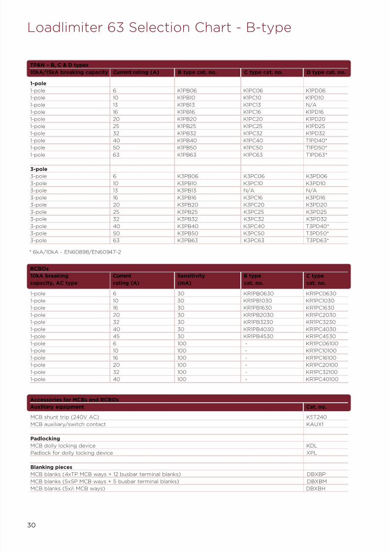
MCB shunt trip (240V AC) KST240
MCB auxiliary/switch contact KAUX1
Padlocking
MCB dolly locking device KDL
Padlock for dolly locking device XPL
Blanking pieces
MCB blanks (4xTP MCB ways + 12 busbar terminal blanks) DBXBP
MCB blanks (5xSP MCB ways + 5 busbar terminal blanks) DBXBMMCB blanks (5x1 ⁄ 2 MCB ways) DBXBH
1-pole 6 30 KR1PB0630 KR1PC0630
1-pole 10 30 KR1PB1030 KR1PC1030
1-pole 16 30 KR1PB1630 KR1PC1630
1-pole 20 30 KR1PB2030 KR1PC2030
1-pole 32 30 KR1PB3230 KR1PC3230
1-pole 40 30 KR1PB4030 KR1PC4030
1-pole 45 30 KR1PB4530 KR1PC4530
1-pole 6 100 - KR1PC06100
1-pole 10 100 - KR1PC10100
1-pole 16 100 - KR1PC16100
1-pole 20 100 - KR1PC20100
1-pole 32 100 - KR1PC32100
1-pole 40 100 - KR1PC40100
RCBOs
10kA breaking Current Sensitivity B type C type
capacity, AC type rating (A) (mA) cat. no. cat. no.
Loadlimiter 63 Selection Chart - B-type
1-pole
1-pole 6 K1PB06 K1PC06 K1PD06
1-pole 10 K1PB10 K1PC10 K1PD101-pole 13 K1PB13 K1PC13 N/A
1-pole 16 K1PB16 K1PC16 K1PD16
1-pole 20 K1PB20 K1PC20 K1PD20
1-pole 25 K1PB25 K1PC25 K1PD25
1-pole 32 K1PB32 K1PC32 K1PD32
1-pole 40 K1PB40 K1PC40 T1PD40*
1-pole 50 K1PB50 K1PC50 T1PD50*
1-pole 63 K1PB63 K1PC63 T1PD63*
3-pole
3-pole 6 K3PB06 K3PC06 K3PD06
3-pole 10 K3PB10 K3PC10 K3PD10
3-pole 13 K3PB13 N/A N/A3-pole 16 K3PB16 K3PC16 K3PD16
3-pole 20 K3PB20 K3PC20 K3PD20
3-pole 25 K3PB25 K3PC25 K3PD25
3-pole 32 K3PB32 K3PC32 K3PD32
3-pole 40 K3PB40 K3PC40 T3PD40*
3-pole 50 K3PB50 K3PC50 T3PD50*
3-pole 63 K3PB63 K3PC63 T3PD63*
TP&N – B, C & D types
10kA/15kA breaking capacity Current rating (A) B type cat. no. C type cat. no. D type cat. no.
Accessories for MCBs and RCBOs
Auxiliary equipment Cat. no.
* 6kA/10kA - EN60898/EN60947-2

7/21/2019 TE Dorman Smith Product Portofolio 2011
http://slidepdf.com/reader/full/te-dorman-smith-product-portofolio-2011 33/182
31
Modular contactor, 20 2P N/O 17.5 EE2P20COAC1 230V
Modular contactor, 20 2P N/C 17.5 EE2P20CCAC1 230V
Modular contactor, 25 4P N/O 35 EE4P25COAC1 400V
Modular contactor, 25 4P N/C 35 EE4P25CCAC1 400V
Modular contactor, 40 4P N/O 35 EE4P25CCAC1 400V
Modular contactor, 40 4P N/C 35 EE4P40CCAC1 400V
Modular contactor, 63 4P N/O 54 EE4P63COAC1 400V
Modular contactor, 63 4P N/C 54 EE4P63CCAC1 400V
Venting kit 9 LLMV
Contactor Current Rating (A) Contacts Width (mm) Cat. no.
Timer 16A (AC7A) 1 or 2 channel 35 DRT-DW2R
Programmable Timer
Loadlimiter 63 Selection Chart - B-type
Type AC 40 30mA 35 EE40/30/2Type AC 40 100mA 35 EE40/100/2Type AC 63 30mA 35 EE63/30/2Type AC 63 100mA 35 EE63/100/2Type AC 63 300mA 35 EE63/300/2Type AC 80 30mA 35 EE80/30/2Type AC 100 30mA 35 EE100/30/2Type AC 100 100mA 35 EE100/100/2Type AC time delay 100 100mA 35 EES100/100/2
2-pole RCCB
Description Current rating (A) Function Width (mm) Cat. no.
Type AC 40 30mA 70 EE40/30/4Type AC 40 100mA 70 EE40/100/4Type AC 63 30mA 70 EE63/30/4Type AC 63 100mA 70 EE63/100/4
Type AC 63 300mA 70 EE63/300/4Type AC 80 30mA 70 EE80/30/4Type AC 100 30mA 70 EE100/30/4Type AC 100 100mA 70 EE100/100/4Type AC time delay 100 100mA 70 EES100/100/4
4-pole RCCB
Description Current rating (A) Sensitivity Width (mm) Cat. no.

7/21/2019 TE Dorman Smith Product Portofolio 2011
http://slidepdf.com/reader/full/te-dorman-smith-product-portofolio-2011 34/182
32
B-type Distribution Boards (without incoming device)
4 1 544 10 DBX04R6 1 598 11 DBX06R
8 1 651 12 DBX08R
12 1 758 15 DBX12R
16 1 865 18 DBX16R
20 1 1025 22 DBX20R
24 1 1132 27 DBX24R
3-pole ways Drawing Height Weight Cat. no.
no. (mm) (kg)
YA3 Frame MCCB Enclosure for B-type Distribution Boards
3-pole MCCB 2 321 8 DBXYA3
4-pole MCCB 2 321 8 DBXYA3
Incomer Drawing Height Weight Cat. no.
no. (mm) (kg)
1
2
3
All dimensions in mm
18 x 1-pole ways(single row) 213 5 DBS18X
36 x 1-pole ways(double row) 427 8 DBS36X
General purposeenclosure 213 3 DBMSB
Modular ways Height (mm) Weight (kg) Cat. no.
Supplied without top or bottom plate. Intended for use with removable plate fromdistribution board.
Loadlimiter 63Outline Drawings and Dimensions
7/21/2019 TE Dorman Smith Product Portofolio 2011
http://slidepdf.com/reader/full/te-dorman-smith-product-portofolio-2011 35/182
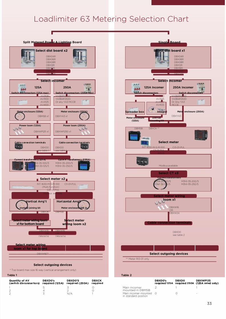
Loadlimiter 63 Metering Selection Chart
Split Metered Power & Lighting Board Single Board
125A 250A
YA3B3P250D
YA3B4P250D
Or any YA3 MCCB
AV3125
AV3100
AV4125
AV4100
125A Incomer 250A Incomer
AV3100
AV3125
AV4100
AV4125
Integral
DBXW16
OR
DBXW24
DBXW16T*
DBXW16
OR
DBXW24
Select meter wiring loom
x1 for bottom board
Select meter wiringloom x1 for top board
Select meterwiring loom x2
Vertical Arrg’t Horizontal Arrg’t
DBMSBDBXJK
YA3B3P250D
YA3B4P250D
Or Any YA3
MCCB
Spreader box
Select dist board x2
DBX04RDBX06R
DBX08R
DBX12R
DBX16R
DBX20R
DBX24R
Select incomer
M3N1-35-100/5
M3N1-35-125/5
M3N1-35-200/5
M3N1-35-250/5
DBXD0
see table 1
DBXD0
see table 1
DBXWP125 x1 DBXWP250 x1
DBMSB x1 DBXYA3 x1 DBXYA3
Select meter x2
INT-1630-M-5-M-100
(Multi-function)
CI3-01-PUL
CI1-01-PUL
Select outgoing devices
* Top board max size 16 way (vertical arrangement only)
Select dist board x1
DBX04RDBX06R
DBX08R
DBX12R
DBX16R
DBX20R
DBX24R
Select incomer
Select meter
** Meter RI3-01 only
Select CT x3
M3N1-35-100/5
M3N1-35-125/5
M3N1-35-200/5
M3N1-35-250/5
DBXW16
OR
DBXW24
Select meter wiringloom x1
Cable connection terminals
DBXD0
see table 2
INT-1630-M-5-M-100
CI1-01-PUL
RI3-01
CI3-01-PUL
Select outgoing devices
Switch disconnectors (125A max)
Meter enclosure (125A)
Meter enclosure
(125A)
DIN-rail
mounting kit
Meter enclosure (250A) Meter enclosure (250A)
Power loom (125A) Power loom (250A)
Cable connection terminals Cable connection terminals
Current transformers (125A) Current transformers (250A)
Current transformers
Vertical joining kit Meter enclosure (DB 2)
Switch disconnectors (250A max) Switch disconnectors Switch disconnectors
DBMSB DBXCK **
1 5 3 02 4 2 02 3 N/A 1
Quantity of AV DBXD0's DBXD0'S DBXCK(switch disconnectors) required (125A) required (250A) required
Main incomer 2 1 1mounted in DBMSBMain incomer mounted 0 0 -in standard position
DBXD0’s DBXD0 DBXWP125required 125A required 250A (125A rated only)
Table 1 Table 2
33
Modbus available
Modbus available

7/21/2019 TE Dorman Smith Product Portofolio 2011
http://slidepdf.com/reader/full/te-dorman-smith-product-portofolio-2011 36/182
34
Example 1 Requirement – Vertically stacked, 125A split meteredpower and lighting distribution board• 8 way TP&N power board• 6 TP&N lighting board• Multi-function meters
DBX08R 1 8 way TP&N distribution board
DBX06R 1 6 way TP&N distribution board
AV3125 1 125A – 3P switch disconnector
DBMSB 1 Spreader box with facility to mount 2 panelmounted meters
DBXJK 1 Mechanical joining kit for joining twovertically stacked distribution boards
DBXWP125 1 Power loom for split metered distributionboard (125A)
INT-1630-M-5-M-100 2 3-Phase Integra 1630 multi-function meterwith 1 pulse output
DBXW16 1 Wiring loom for single meter
DBXW16T 1 Wiring loom for single meter for topdistribution board when vertically stacked
DBXD0 5 Cable joining terminal kit
M3N1-35-125/5 2 125A 3-in-1 current transformers
Cat. no. Quantity Description
Flow Chart Examples
Example 1: Bill of Material List
Example 2: Bill of Material List
Example 2 Requirement – Single Metered Distribution Board (250A)• 24 way TP&N distribution board• KWh meter
DBX24R 1 24 way TP&N distribution board
YA3B3P250D 1 250A–3P MCCB switch disconnector
DBXYA3 1 250A incoming enclosure with facility tomount 2 panel mounted meters
CI1-01-PUL 1 3-phase Kilowatt hour meter with 1 pulseoutput (panel mounted)
DBXW24 1 Wiring loom for single meter
DBXD0 1 Cable joining terminal kit
M3N1-35-250/5 1 250A current transformers
Cat. no. Quantity Description
Split metered 125A
Split metered 250A
Single metered 125A & 250A
7/21/2019 TE Dorman Smith Product Portofolio 2011
http://slidepdf.com/reader/full/te-dorman-smith-product-portofolio-2011 37/182
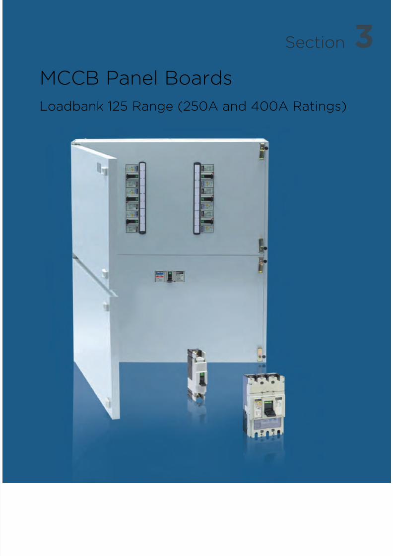
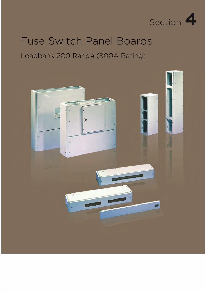
3Section
MCCB Panel Boards
Loadbank 125 Range (250A and 400A Ratings)

7/21/2019 TE Dorman Smith Product Portofolio 2011
http://slidepdf.com/reader/full/te-dorman-smith-product-portofolio-2011 38/182
36
Key Features• ASTA certified busbars with a
short circuit rating of 25kA for1 second (250A) and 25kA for 3seconds (400A)
• Shunts, UVRs and auxiliariesare common for YA2, YA3 andYA5 MCCBs
• Single frame size outgoingMCCBs from 16A to 125A
• Generous cable-spreadingspace for incoming andoutgoing cables
• Common width (700mm) anddepth (190mm) for all enclosures
• A single part number identifiesthe complete main enclosure
Available Options• 250A panel boards with 6, 8 or
12 triple-pole outgoing ways canchoose incoming devices fromthe YA3 MCCB range or adirect connection
• 400A panel boards with 6, 8, 12or 16 triple-pole outgoing wayscan choose incoming devicesfrom the YA5 MCCB range or adirect connection
• Panel build options include:• Cable spreader box• Service centre with 24
single-pole ways• Integra metering housing• YA3 frame outgoing housing
Additional Features• Neutral and earth terminal for
each single-pole way• Clean earth facility• 250A panels use YA3 MCCBs for
incoming devices• 400A panels use YA5 MCCBs
for incoming devices• All versions use YA2 MCCBs for
outgoing devices• All triple-pole MCCBs have
adjustable overload andinstantaneous trips
Compliance
Panel boards EN 60439-1MCCBs EN 60947-2
Overview
Featuring busbar ratings of 250A and 400A with sevenMCCB panel board designs Loadbank 125 system offers
an uncomplicated solution for power distribution incommercial and industrial applications. Outgoing devicesconsist of a single frame size utilising the Loadline YA2frame as a cost effective option for circuit protection.
New developments include ASTA certified busbars with ashort-circuit withstand rating of 25kA-3sec (400Abusbars only) and Form 3 separation is now as standard.
Available options now include a versatile range of
accessories for both incoming and outgoing metering forcompliance with Part L2 Building Regulations. A
multitude of add-on enclosures, including service centresand a unique outgoing housing for 160A to 250A YA3frame MCCB matching the dimensional profile of thestandard enclosure.
The standard finish is epoxy powder coating in light greyRAL 7035.

7/21/2019 TE Dorman Smith Product Portofolio 2011
http://slidepdf.com/reader/full/te-dorman-smith-product-portofolio-2011 39/182
37
MCCB Panel Boards (250A and 400A Rating)
Modular Devices
• Surge protection• Meters, current transformers and
wiring looms• Contactors• Timer• Earth leakage device
MCCB Panel Boards
• Service centres• Metering enclosures
Circuit Protection Devices
• Moulded case circuit breakers (125A max)
Incoming Devices
• Switch disconnector• Moulded case circuit breakers

7/21/2019 TE Dorman Smith Product Portofolio 2011
http://slidepdf.com/reader/full/te-dorman-smith-product-portofolio-2011 40/182
38
250A Panel Board Enclosures• ASTA certified busbars rated 25kA-1sec• Form 3 with outgoing terminals shields fitted• IP4X protection rating• Optional incoming terminal shield available
• Accepts single frame size YA2 MCCB (Max 125A) outgoing devices
No. of TP Incoming device Height Width Depth Cat. no.
outgoing ways type (mm) (mm) (mm)
6 YA3 frame 904 700 190 PB206YA
8 YA3 frame 994 700 190 PB208YA
12 YA3 frame 1174 700 190 PB212YA
Incoming Current rating No. of poles Cat. no.
device type (A)
Switch disconnector 250 3 YA3B3P250D
MCCB 160 3 YA3N3P160TMCCB 200 3 YA3N3P200T
MCCB 250 3 YA3N3P250T
Switch disconnector 250 4 YA3B4P250D
MCCB 160 4 YA3N4P160T
MCCB 200 4 YA3N4P200T
MCCB 250 4 YA3N4P250T
Description Cat. no.
3-pole incoming terminal shroud YA3TS3P
4-pole incoming terminal shroud YA3TS4P
Door cylinder lock DBXCL
Door padlock device DBXPL
3-pole blanking piece LBYA2BP3P
4-pole incoming connection kit PB4PNC250
250A Panel Board Accessories
250A and 400A Panel Board Accessories Add-on Units
• Cable spreader box• 24 way service centre• Housing to accommodate outgoing YA3 MCCB
250A Panel Board Incoming Devices• Standard cable termination 95mm2
• Maximum cable termination is 150mm2 using reduced palm width M8 cable lugs• MCCBs have thermal and magnetic overloads except switch disconnector• Four-pole incoming devices require adapter kit• YA3 cable clamp termination 120mm2 (sold separately)
Description Height (mm) Cat. no.
Cable spreader box 270 PBYA2CSB
Service centre with 24-1 pole ways 270 PBYA2SC24
160A–250A YA3 outgoing housing 450 PBYA2OG
Loadbank 125250A Panel Board Enclosures Form 3 25kA-1sec
7/21/2019 TE Dorman Smith Product Portofolio 2011
http://slidepdf.com/reader/full/te-dorman-smith-product-portofolio-2011 41/182
39
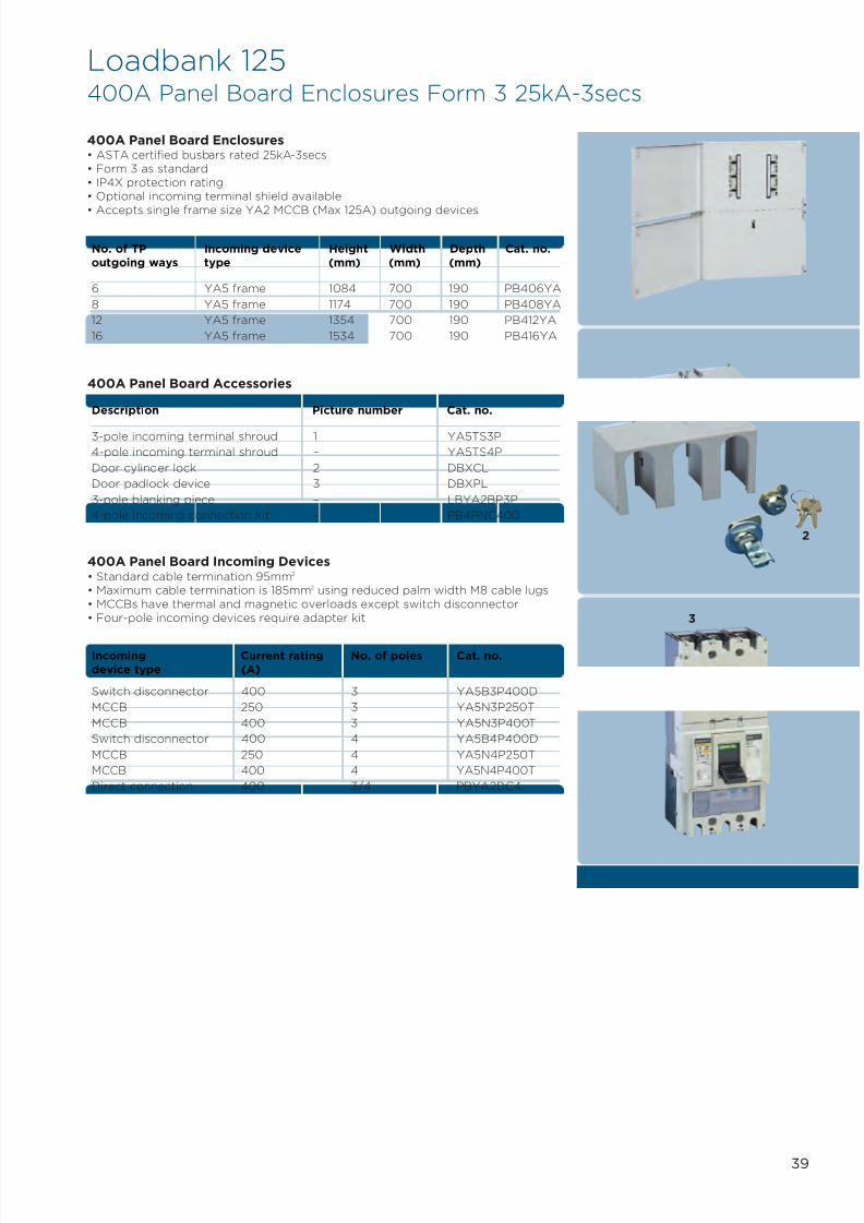
Loadbank 125400A Panel Board Enclosures Form 3 25kA-3secs
400A Panel Board Enclosures• ASTA certified busbars rated 25kA-3secs• Form 3 as standard• IP4X protection rating• Optional incoming terminal shield available
• Accepts single frame size YA2 MCCB (Max 125A) outgoing devices
No. of TP Incoming device Height Width Depth Cat. no.
outgoing ways type (mm) (mm) (mm)
6 YA5 frame 1084 700 190 PB406YA
8 YA5 frame 1174 700 190 PB408YA
12 YA5 frame 1354 700 190 PB412YA
16 YA5 frame 1534 700 190 PB416YA
Description Picture number Cat. no.
3-pole incoming terminal shroud 1 YA5TS3P
4-pole incoming terminal shroud – YA5TS4P
Door cylinder lock 2 DBXCL
Door padlock device 3 DBXPL
3-pole blanking piece – LBYA2BP3P
4-pole incoming connection kit – PB4PNC400
400A Panel Board Accessories
Incoming Current rating No. of poles Cat. no.
device type (A)
Switch disconnector 400 3 YA5B3P400D
MCCB 250 3 YA5N3P250T
MCCB 400 3 YA5N3P400T
Switch disconnector 400 4 YA5B4P400D
MCCB 250 4 YA5N4P250T
MCCB 400 4 YA5N4P400T
Direct connection 400 3/4 PBYA2DC4
400A Panel Board Incoming Devices• Standard cable termination 95mm2
• Maximum cable termination is 185mm2 using reduced palm width M8 cable lugs• MCCBs have thermal and magnetic overloads except switch disconnector• Four-pole incoming devices require adapter kit
1
2
3

7/21/2019 TE Dorman Smith Product Portofolio 2011
http://slidepdf.com/reader/full/te-dorman-smith-product-portofolio-2011 42/182
40
Metering Housing• New stackable meter housing for incoming and outgoing metering• Designed to fit up to six DIN-rail mounted meters (4 mod max)• Can be mounted top or bottom
• Includes DIN-rail for facility to mount current transformers and fuses
Metering Harnesses• A collection of meter harnesses for metering incoming and outgoing circuits• Please refer to page 44 for easy selection chart
Description Cat. no.
Incoming meter loom PBWI
Voltage tap off loom for outgoing metering PBWP
CT harness for 1 meter PBWCT
Power loom for 6 outgoing meters PBWM6
Description Cat. no.
Digital multi-function meter with 1 pulse and RI3-01
1 RS485 Modbus ouputAnalogue kWh meter with 1 pulse DRK-3PCT-415
Description Height (mm) Weight Cat. no.
Meter housing 450 - PBYA2MB
Four Module DIN-rail Meter
Description Max cable size mm2 Cat. no.
250A 3-in-1 CT case size 3 150 M3N1-45-250/5
400A 3-in-1 CT case size 3 150 M3N1-45-400/5
Incoming Current Transformers
Description Max cable size mm2 Cat. no.
60A 3-in-1 current transformer 50 M3N1-25-60/5Case size 25mm
100A 3-in-1 current transformer 50 M3N1-25-100/5Case size 25mm
125A 3-in-1 current transformer 50 M3N1-25-125/5Case size 25mm
Outgoing Current Transformers
Loadbank 125250A/400A Surge Protection and Metering Accessories
Surge Protection Mounting Kits• Easily installed inside panelboard closely located to incoming device• DIN-rail mounting for triple-pole MCB• C/W 30kA three-phase surge protector• Remote status indication
• Site fault indication
Surge protection Loadbank 125 mounting kitc/w surge protector and remote indicator 435 PBSM
Description Height (mm) Cat. no.
7/21/2019 TE Dorman Smith Product Portofolio 2011
http://slidepdf.com/reader/full/te-dorman-smith-product-portofolio-2011 43/182
41
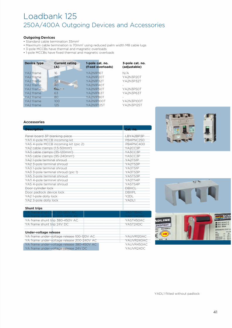
Loadbank 125250A/400A Outgoing Devices and Accessories
Outgoing Devices• Standard cable termination 35mm2
• Maximum cable termination is 70mm2 using reduced palm width M8 cable lugs• 3-pole MCCBs have thermal and magnetic overloads• 1-pole MCCBs have fixed thermal and magnetic overloads
Device type Current rating 1-pole cat. no. 3-pole cat. no.
(A) (fixed overloads) (adjustable)
YA2 frame 16 YA2N1P16T N/A
YA2 frame 20 YA2N1P20T YA2N3P20T
YA2 frame 32 YA2N1P32T YA2N3P32T
YA2 frame 40 YA2N1P40T -
YA2 frame 50 YA2N1P50T YA2N3P50T
YA2 frame 63 YA2N1P63T YA2N3P63T
YA2 frame 80 YA2N1P80T -
YA2 frame 100 YA2N1P100T YA2N3P100T
YA2 frame 125 YA2N1P125T YA2N3P125T
Accessories
Description Cat. no.
Panel board 3P blanking piece LBYA2BP3P
YA3 4-pole MCCB incoming kit PB4PNC250
YA5 4-pole MCCB incoming kit (pic 2) PB4PNC400
YA2 cable clamps (1.5-50mm2) YA2CC3P
YA3 cable clamps (35-120mm2) YA3CC3P
YA5 cable clamps (95-240mm2) YA5CC3P
YA2 1-pole terminal shroud YA2TS1P
YA2 3-pole terminal shroud YA2TS3P
YA3 1-pole terminal shroud YA3TS1P
YA3 3-pole terminal shroud (pic 1) YA3TS3PYA5 3-pole terminal shroud YA5TS3P
YA3 4-pole terminal shroud YA3TS4P
YA5 4-pole terminal shroud YA5TS4P
Door cylinder lock DBXCL
Door padlock device lock DBXPL
YA2 1-pole dolly lock Y2DL
YA2 3-pole dolly lock YADL1
Shunt trips
YA frame shunt trip 100-120V AC YAST115AC
YA frame shunt trip 200-240V AC YAST240AC
YA frame shunt trip 380-450V AC YAST450AC
YA frame shunt trip 24V DC YAST24DC
Under-voltage release
YA frame under-voltage release 100-120V AC YAUVR120AC
YA frame under-voltage release 200-240V AC YAUVR240AC
YA frame under-voltage release 380-450V AC YAUVR450AC
YA frame under-voltage release 24V DC YAUVR24DC
1
2
YADL1 fitted without padlock
7/21/2019 TE Dorman Smith Product Portofolio 2011
http://slidepdf.com/reader/full/te-dorman-smith-product-portofolio-2011 44/182
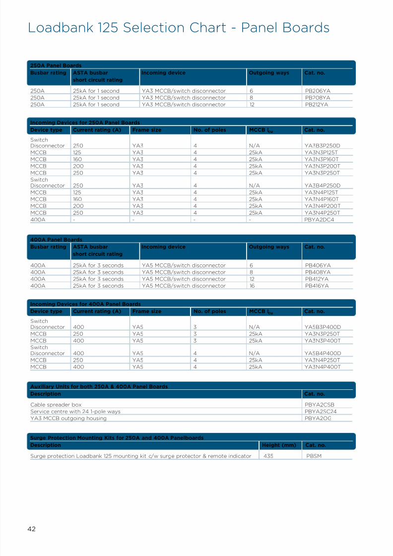
Surge protection Loadbank 125 mounting kit c/w surge protector & remote indicator 435 PBSM
Surge Protection Mounting Kits for 250A and 400A Panelboards
Description Height (mm) Cat. no.
42
Auxiliary Units for both 250A & 400A Panel BoardsDescription Cat. no.
SwitchDisconnector 400 YA5 3 N/A YA5B3P400D
MCCB 250 YA5 3 25kA YA3N3P250T
MCCB 400 YA5 3 25kA YA3N3P400T
SwitchDisconnector 400 YA5 4 N/A YA5B4P400D
MCCB 250 YA5 4 25kA YA3N4P250T
MCCB 400 YA5 4 25kA YA3N4P400T
Incoming Devices for 400A Panel Boards
Device type Current rating (A) Frame size No. of poles MCCB Icu Cat. no.
400A 25kA for 3 seconds YA5 MCCB/switch disconnector 6 PB406YA
400A 25kA for 3 seconds YA5 MCCB/switch disconnector 8 PB408YA
400A 25kA for 3 seconds YA5 MCCB/switch disconnector 12 PB412YA
400A 25kA for 3 seconds YA5 MCCB/switch disconnector 16 PB416YA
400A Panel Boards
Busbar rating ASTA busbar Incoming device Outgoing ways Cat. no.
short circuit rating
SwitchDisconnector 250 YA3 4 N/A YA3B3P250D
MCCB 125 YA3 4 25kA YA3N3P125T
MCCB 160 YA3 4 25kA YA3N3P160T
MCCB 200 YA3 4 25kA YA3N3P200T
MCCB 250 YA3 4 25kA YA3N3P250T
SwitchDisconnector 250 YA3 4 N/A YA3B4P250D
MCCB 125 YA3 4 25kA YA3N4P125TMCCB 160 YA3 4 25kA YA3N4P160T
MCCB 200 YA3 4 25kA YA3N4P200T
MCCB 250 YA3 4 25kA YA3N4P250T
400A - - - - PBYA2DC4
Incoming Devices for 250A Panel Boards
Device type Current rating (A) Frame size No. of poles MCCB Icu Cat. no.
Loadbank 125 Selection Chart - Panel Boards
250A 25kA for 1 second YA3 MCCB/switch disconnector 6 PB206YA
250A 25kA for 1 second YA3 MCCB/switch disconnector 8 PB208YA250A 25kA for 1 second YA3 MCCB/switch disconnector 12 PB212YA
250A Panel Boards
Busbar rating ASTA busbar Incoming device Outgoing ways Cat. no.
short circuit rating
Cable spreader box PBYA2CSB
Service centre with 24 1-pole ways PBYA2SC24
YA3 MCCB outgoing housing PBYA2OG
7/21/2019 TE Dorman Smith Product Portofolio 2011
http://slidepdf.com/reader/full/te-dorman-smith-product-portofolio-2011 45/182
43
Loadbank 125 Selection Chart - Panel Boards
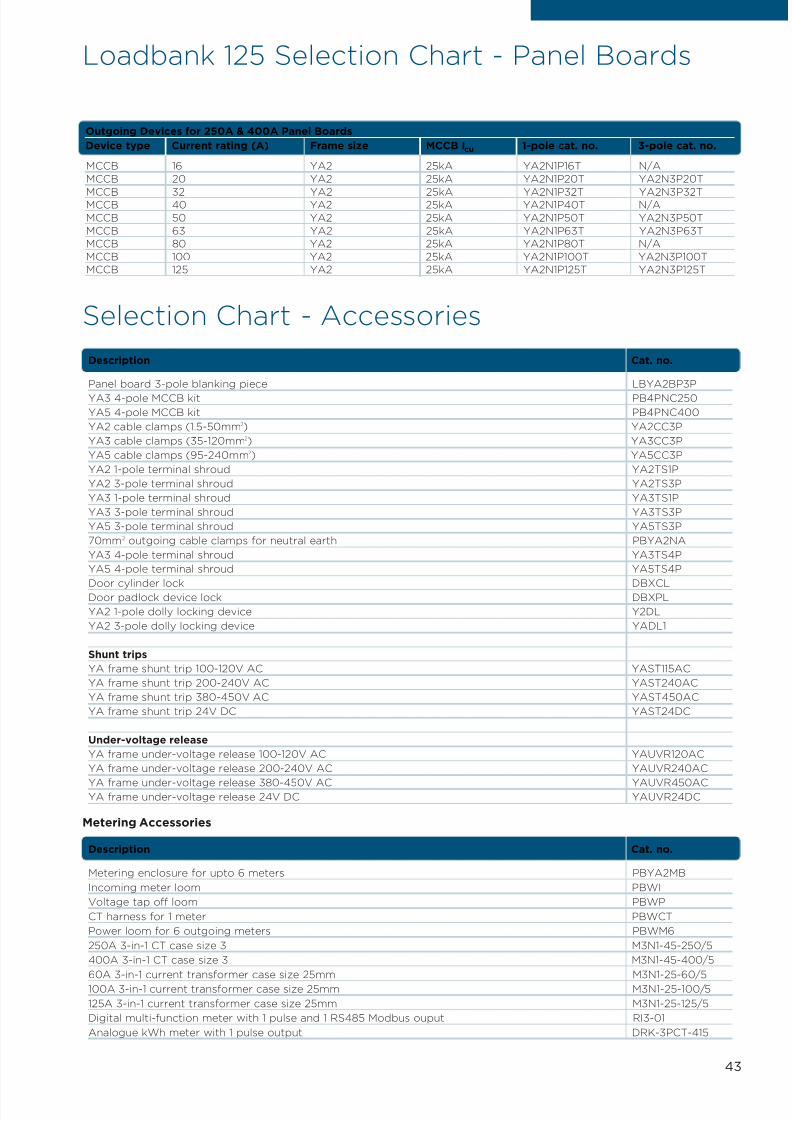
Selection Chart - Accessories
Description Cat. no.
Panel board 3-pole blanking piece LBYA2BP3P
YA3 4-pole MCCB kit PB4PNC250
YA5 4-pole MCCB kit PB4PNC400
YA2 cable clamps (1.5-50mm2) YA2CC3P
YA3 cable clamps (35-120mm2) YA3CC3P
YA5 cable clamps (95-240mm2) YA5CC3P
YA2 1-pole terminal shroud YA2TS1P
YA2 3-pole terminal shroud YA2TS3P
YA3 1-pole terminal shroud YA3TS1P
YA3 3-pole terminal shroud YA3TS3P
YA5 3-pole terminal shroud YA5TS3P
70mm2 outgoing cable clamps for neutral earth PBYA2NA
YA3 4-pole terminal shroud YA3TS4P
YA5 4-pole terminal shroud YA5TS4P
Door cylinder lock DBXCLDoor padlock device lock DBXPL
YA2 1-pole dolly locking device Y2DL
YA2 3-pole dolly locking device YADL1
Shunt trips
YA frame shunt trip 100-120V AC YAST115AC
YA frame shunt trip 200-240V AC YAST240AC
YA frame shunt trip 380-450V AC YAST450AC
YA frame shunt trip 24V DC YAST24DC
Under-voltage release
YA frame under-voltage release 100-120V AC YAUVR120AC
YA frame under-voltage release 200-240V AC YAUVR240AC
YA frame under-voltage release 380-450V AC YAUVR450ACYA frame under-voltage release 24V DC YAUVR24DC
Metering Accessories
Description Cat. no.
Metering enclosure for upto 6 meters PBYA2MB
Incoming meter loom PBWI
Voltage tap off loom PBWP
CT harness for 1 meter PBWCT
Power loom for 6 outgoing meters PBWM6
250A 3-in-1 CT case size 3 M3N1-45-250/5
400A 3-in-1 CT case size 3 M3N1-45-400/5
60A 3-in-1 current transformer case size 25mm M3N1-25-60/5100A 3-in-1 current transformer case size 25mm M3N1-25-100/5
125A 3-in-1 current transformer case size 25mm M3N1-25-125/5
Digital multi-function meter with 1 pulse and 1 RS485 Modbus ouput RI3-01
Analogue kWh meter with 1 pulse output DRK-3PCT-415
MCCB 16 YA2 25kA YA2N1P16T N/A
MCCB 20 YA2 25kA YA2N1P20T YA2N3P20T
MCCB 32 YA2 25kA YA2N1P32T YA2N3P32TMCCB 40 YA2 25kA YA2N1P40T N/A
MCCB 50 YA2 25kA YA2N1P50T YA2N3P50T
MCCB 63 YA2 25kA YA2N1P63T YA2N3P63T
MCCB 80 YA2 25kA YA2N1P80T N/A
MCCB 100 YA2 25kA YA2N1P100T YA2N3P100T
MCCB 125 YA2 25kA YA2N1P125T YA2N3P125T
Outgoing Devices for 250A & 400A Panel Boards
Device type Current rating (A) Frame size MCCB Icu 1-pole cat. no. 3-pole cat. no.
7/21/2019 TE Dorman Smith Product Portofolio 2011
http://slidepdf.com/reader/full/te-dorman-smith-product-portofolio-2011 46/182
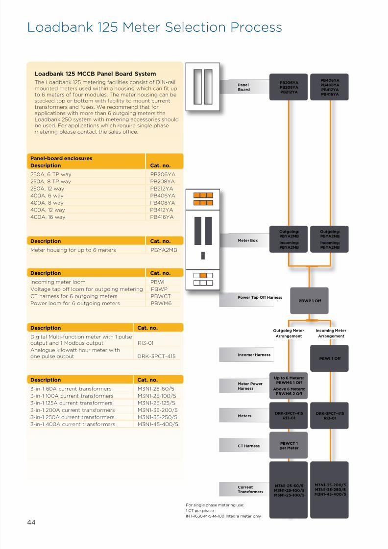
PanelBoard
PB206YAPB208YA
PB212YA
PB406YA
PB408YA
PB412YA
PB416YA
Meter Box
Outgoing:PBYA2MB
Incoming:
PBYA2MB
Outgoing:
PBYA2MB
Incoming:PBYA2MB
PBWP 1 Off
Outgoing Meter
Arrangement
PBWI 1 Off
Incoming Meter
Arrangement
Power Tap Off Harness
Incomer Harness
Up to 6 Meters:
PBWM6 1 OffAbove 6 Meters:
PBWM6 2 Off
Meter PowerHarness
DRK-3PCT-415
Ri3-01DRK-3PCT-415
Ri3-01Meters
PBWCT 1per Meter
CT Harness
M3N1-25-60/5M3N1-25-100/5
M3N1-25-100/5
M3N1-35-200/5
M3N1-35-250/5M3N1-45-400/5
CurrentTransformers
For single phase metering use:
1 CT per phase
INT-1630-M-5-M-100 Integra meter only
44
Panel-board enclosures
Description Cat. no.
250A, 6 TP way PB206YA
250A, 8 TP way PB208YA
250A, 12 way PB212YA
400A, 6 way PB406YA
400A, 8 way PB408YA
400A, 12 way PB412YA
400A, 16 way PB416YA
Loadbank 125 MCCB Panel Board System
The Loadbank 125 metering facilities consist of DIN-railmounted meters used within a housing which can fit up
to 6 meters of four modules. The meter housing can bestacked top or bottom with facility to mount currenttransformers and fuses. We recommend that forapplications with more than 6 outgoing meters theLoadbank 250 system with metering accessories shouldbe used. For applications which require single phasemetering please contact the sales office.
Description Cat. no.
Meter housing for up to 6 meters PBYA2MB
Description Cat. no.
Incoming meter loom PBWI
Voltage tap off loom for outgoing metering PBWP
CT harness for 6 outgoing meters PBWCT
Power loom for 6 outgoing meters PBWM6
Description Cat. no.
Digital Multi-function meter with 1 pulseoutput and 1 Modbus output RI3-01
Analogue kilowatt hour meter withone pulse output DRK-3PCT-415
Description Cat. no.
3-in-1 60A current transformers M3N1-25-60/5
3-in-1 100A current transformers M3N1-25-100/5
3-in-1 125A current transformers M3N1-25-125/5
3-in-1 200A current transformers M3N1-35-200/5
3-in-1 250A current transformers M3N1-35-250/5
3-in-1 400A current transformers M3N1-45-400/5
Loadbank 125 Meter Selection Process
7/21/2019 TE Dorman Smith Product Portofolio 2011
http://slidepdf.com/reader/full/te-dorman-smith-product-portofolio-2011 47/182
4Section
Fuse Switch Panel Boards
Loadbank 200 Range (800A Rating)

7/21/2019 TE Dorman Smith Product Portofolio 2011
http://slidepdf.com/reader/full/te-dorman-smith-product-portofolio-2011 48/182
46
Key Features• ASTA certified short circuit
withstand rating• Allows inclusion of TP&N
and four-pole fuse
switch distribution• Generous cable-spreadingspace for incoming andoutgoing cables
• Common width (750mm)and depth (200mm) forall enclosures
Available Options• 800A panel boards with 6 or 10
outgoing fuse switch ways• 400A, 630A or 800A fuse
switch incomers• Panel build options include:
• SP&N MCB distribution
board for 17 ways• TP&N distribution boardwith 6 and 12 ways
• TP&N distribution board withdouble banks of 12 ways
• General purpose enclosureswith uncut front plates
• Metering housings andservice centres
• Current transformers
Additional Features• Add-on incomer units include
all copper connections andincoming cable shrouds
• Panel and distribution boardsexceed EN 60439-1requirements
• Fully shielded busbars andinterconnections ondistribution boards
• Various locking options• IP4X Ingress Protection
ComplianceSwitch fuse panelboards EN 60439-1Skeleton switches EN 60947-3
Overview
Based on the modular system employed withinLoadbank 250 panel board, Loadbank 200 panel board
is designed to fulfil the need for fuse switchpanelboards upto 800A. Panel board enclosures areavailable in either 6 or 10 TP&N outgoing waysfeaturing devices from 63A to 200A. Form 2 separationis provided as standard, with Form 4 shielding as anavailable option.
Several incoming options can be selected from 200A to800A and a comprehensive range of metering facilitiesfor compliance with Building Regulations Part L2
completes this versatile panel board system.
The standard finish is epoxy powder coating in lightgrey RAL 7035.
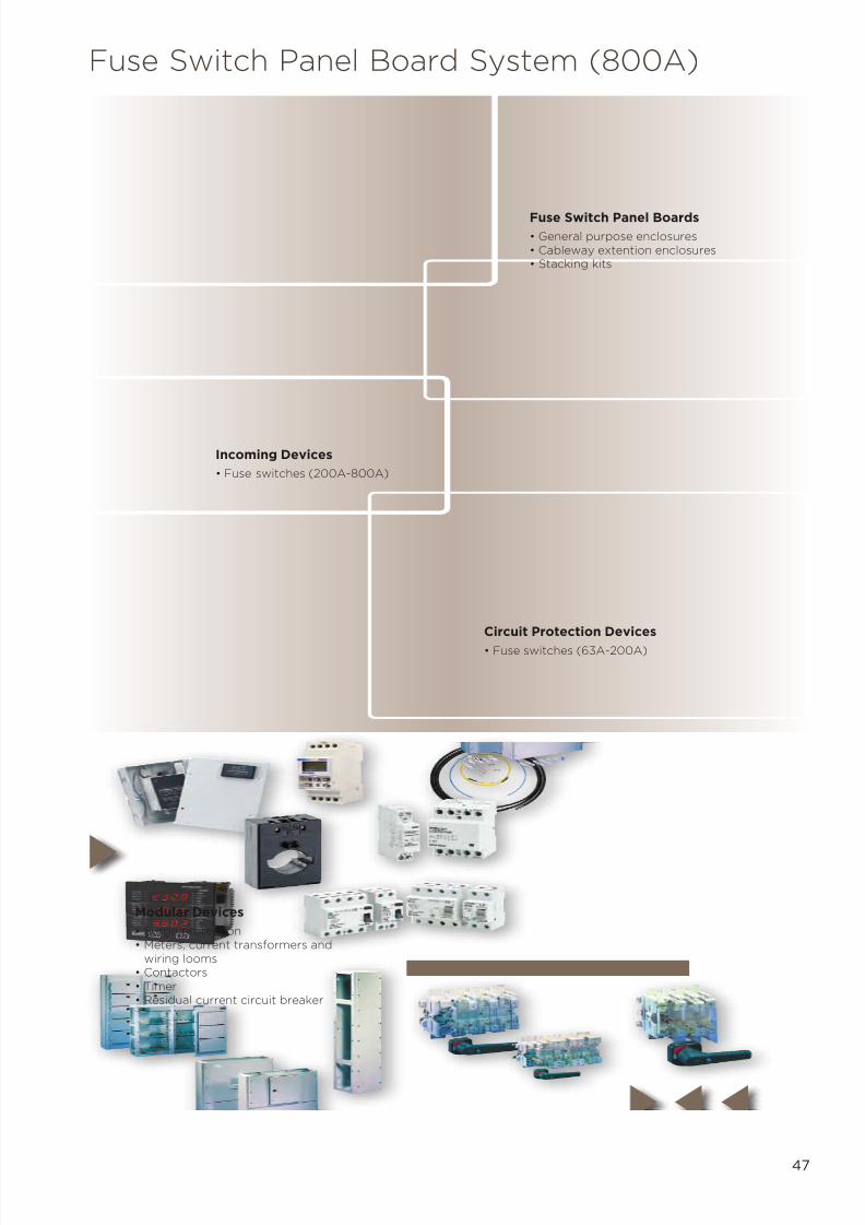
7/21/2019 TE Dorman Smith Product Portofolio 2011
http://slidepdf.com/reader/full/te-dorman-smith-product-portofolio-2011 49/182
47
Fuse Switch Panel Board System (800A)
Modular Devices
• Surge protection• Meters, current transformers and
wiring looms• Contactors• Timer• Residual current circuit breaker
Fuse Switch Panel Boards
• General purpose enclosures• Cableway extention enclosures• Stacking kits
Circuit Protection Devices
• Fuse switches (63A-200A)
Incoming Devices
• Fuse switches (200A-800A)
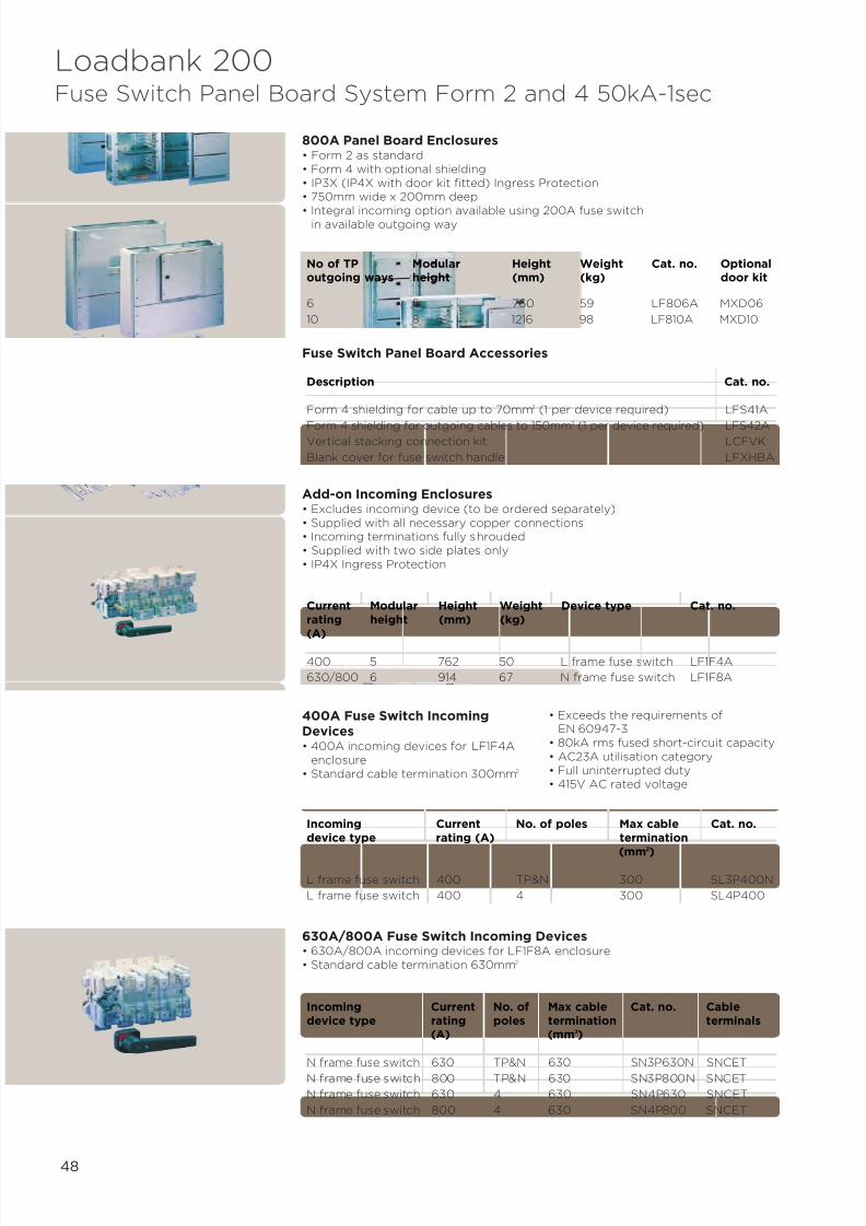
7/21/2019 TE Dorman Smith Product Portofolio 2011
http://slidepdf.com/reader/full/te-dorman-smith-product-portofolio-2011 50/182
400A Fuse Switch IncomingDevices• 400A incoming devices for LF1F4A
enclosure• Standard cable termination 300mm2
• Exceeds the requirements ofEN 60947-3
• 80kA rms fused short-circuit capacity• AC23A utilisation category• Full uninterrupted duty• 415V AC rated voltage
630A/800A Fuse Switch Incoming Devices• 630A/800A incoming devices for LF1F8A enclosure• Standard cable termination 630mm2
Incoming Current No. of poles Max cable Cat. no.device type rating (A) termination
(mm2
)
L frame fuse switch 400 TP&N 300 SL3P400N
L frame fuse switch 400 4 300 SL4P400
Incoming Current No. of Max cable Cat. no. Cabledevice type rating poles termination terminals
(A) (mm2)
N frame fuse switch 630 TP&N 630 SN3P630N SNCET
N frame fuse switch 800 TP&N 630 SN3P800N SNCET
N frame fuse switch 630 4 630 SN4P630 SNCET
N frame fuse switch 800 4 630 SN4P800 SNCET
48
800A Panel Board Enclosures• Form 2 as standard• Form 4 with optional shielding• IP3X (IP4X with door kit fitted) Ingress Protection• 750mm wide x 200mm deep
• Integral incoming option available using 200A fuse switchin available outgoing way
No of TP Modular Height Weight Cat. no. Optionaloutgoing ways height (mm) (kg) door kit
6 5 760 59 LF806A MXD06
10 8 1216 98 LF810A MXD10
Description Cat. no.
Form 4 shielding for cable up to 70mm2 (1 per device required) LFS41A
Form 4 shielding for outgoing cables to 150mm2
(1 per device required) LFS42AVertical stacking connection kit LCFVK
Blank cover for fuse switch handle LFXHBA
Current Modular Height Weight Device type Cat. no.rating height (mm) (kg)(A)
400 5 762 50 L frame fuse switch LF1F4A
630/800 6 914 67 N frame fuse switch LF1F8A
Add-on Incoming Enclosures• Excludes incoming device (to be ordered separately)• Supplied with all necessary copper connections• Incoming terminations fully shrouded• Supplied with two side plates only• IP4X Ingress Protection
Fuse Switch Panel Board Accessories
Loadbank 200Fuse Switch Panel Board System Form 2 and 4 50kA-1sec

7/21/2019 TE Dorman Smith Product Portofolio 2011
http://slidepdf.com/reader/full/te-dorman-smith-product-portofolio-2011 51/182
49
Loadbank 200Outgoing Devices
63/125A Skeleton Switches• Exceeds the requirements of
EN 60947-3• 80kA rms fused short-circuit capacity
• AC23A utilisation category• Full uninterrupted duty• 415V AC rated voltage
Current rating (A) 1-pole+N cat. no. 3-pole+N cat. no. 4-pole cat. no.
63 - SF3P63N SF4P63
100 - SF3P100N SF4P100
125 - SF3P125N SF4P125
160/200A Skeleton Switches• Exceeds the requirements of
EN 60947-3• 80kA rms fused short-circuit capacity
• AC23A utilisation category• Full uninterrupted duty• 415V AC rated voltage
Current rating (A) 1-pole+N cat. no. 3-pole+N cat. no. 4-pole cat. no.
160 - SF3P160N SF4P160200 - SF3P200N SF4P200
Accessories for Outgoing/Incoming Skeleton Switches
Description Current rating (A) Picture Cat. no.
Solid links (set of 1) 63 1 HFL63
Solid links (set of 1) 100/200 1 HFL200A
2-bank auxiliary switch 63/200 2 SAUX2F
4-bank auxiliary switch 63/200 2 SAUX4F
Terminal shrouds and barriers 63/200 – SFTSS
Terminal barriers (set of 3) 63/200 – SFTB
Cable extension terminals 630/800 – SNCET(set of 8)
Solid links (set of 1) 400 1 HLL400
Solid links (set of 1) 630/800 1 HNL800
2-bank auxiliary switch 400/630/800 2 SAUX2N
4-bank auxiliary switch 400/630/800 2 SAUX4N6-bank auxiliary switch 400/630/800 2 SAUX6N
Terminal shrouds and barriers 400 – SLTS
Terminal shrouds and barriers 630/800 – SNTS
Terminal barriers (set of 3) 400 – SLTB
Terminal barriers (set of 3) 630/800 – Supplied
1
2
Loadbank 200Outgoing Devices Accessories

7/21/2019 TE Dorman Smith Product Portofolio 2011
http://slidepdf.com/reader/full/te-dorman-smith-product-portofolio-2011 52/182
50
Loadbank 200Add-on Enclosures
General Purpose Enclosures• IP4X Ingress Protection• Enclosures are 750mm wide x 200 deep• No top or bottom plates supplied (supplied with panel board)
Description Modular height Height (mm) Cat. no.
General purpose enclosure 1 152 LEBM1
General purpose enclosure 2 305 LEBM2
General purpose enclosure 3 457 LEBM3
General purpose enclosure 4 609 LEBM4
General purpose enclosure 5 762 LEBM5
General purpose enclosure 6 914 LEBM6
Cableway Extension Enclosures• IP4X Ingress Protection• Recommend for cables above 70mm2
• 250mm wide x 200mm deep• No side plates supplied (supplied with panel board)
Description Modular height Height (mm) Cat. no.
Cableway 1 152 LECM1
Cableway 2 305 LECM2
Cableway 3 457 LECM3
Cableway 4 609 LECM4
Cableway 5 762 LECM5
Cableway 6 914 LECM6
Cableway 8 1219 LECM8
MCB Distribution Board and Service Centre• IP3X (IP4X with door fitted) Ingress Protection• MCB distribution boards have fully shielded busbars and interconnections• Space saving twin option TP&N distribution board option
*Only double module RCBOs can be fitted in this enclosure.
Description Modular Height Cat. no. Door kitheight (mm) cat. no.
17 MCB way SP&N distribution board 1 152 LDS17 LD1DS
6 TP way TP&N distribution board 2 305 LDT106X LD1D06X
12 TP way TP&N distribution board 3 457 LDT112X LD1D12X
2 x 12 TP way TP&N distribution board 4 609 LDT212X* LD2D12X
24 way modular service centre 1 152 LDS24 LD1DS
Transient Voltage Surge Protector Cableway Mounting Kits• Easily installed within a standard cableway (2 modules onward)• DIN-rail mounting for triple-pole MCB• C/W 30Ka three-phase surge protector• Remote status indication• Site fault indication
Cableway mounting frame c/w surge protector
& remote indicator (1) 304 LECK2SM2 module enclosure c/w surge protector& remote indicator (2) 304 LECK2SP
Description Height (mm) Cat. no.
1
2

7/21/2019 TE Dorman Smith Product Portofolio 2011
http://slidepdf.com/reader/full/te-dorman-smith-product-portofolio-2011 53/182
51
Loadbank 200Metering Accessories
Description Height Cat. no.
2 module metering door kit, excluding CTs and control wiring 2 LECMD2
3 module metering door kit, excluding CTs and control wiring 3 LECMD3
4 module metering door kit, excluding CTs and control wiring 4 LECMD4
5 module metering door kit, excluding CTs and control wiring 5 LECMD5
6 module metering door kit, excluding CTs and control wiring 6 LECMD6
8 module metering door kit, excluding CTs and control wiring 8 LECMD8
*Using standard lugs**Using reduced palm width lugs
For easy selection of metering please refer to the charts on pages 56.
Cableway Metering Door Kits• Incoming and outgoing metering utilises cableway extension boxes• Metering door kits are available sized to the cableway extension boxes and are
designed for panel mounted meters• Includes DIN-rail for facility to mount current transformers and fuses
Description Cat. no.
Incoming meter loom LBWI
Voltage tap off loom for outgoing metering LBWP
CT harness for 1 outgoing meters LBWCT
Power loom for 6 outgoing meters LBWM6
Metering Harnesses
Description Cat. no.
Digital multi-function meter with one pulse output INT-1630-M-5-M-100
Digital multi-function meter with one pulse output and INT-1630-M-5-M-110one RS485 output
Digital kilowatt hour meter with pulse output CI1-01-PUL
Digital multi-function meter with pulse output CI3-01-PUL
Pulse Output for Ci meter CI-PUL-01
RS485 Modbus Output for Ci meter CI-MOD-01
Description Max cable size mm2 Cat. no.
100A 3-in-1 CT Case size 35mm 95*/150** M3N1-35-100/5
125A 3-in-1 CT Case size 35mm 95*/150** M3N1-35-125/5
200A 3-in-1 CT Case size 35mm 95*/150** M3N1-35-200/5250A 3-in-1 CT Case size 35mm 95*/150** M3N1-35-250/5
Outgoing Current Transformers
Description Max cable size mm2 Cat. no.
400A current transformer (sold singular) 185*/240** M63N-400/5
600A current transformer (sold singular) 185*/240** M63N-600/5
800A current transformer (sold singular) 240 M93L-800/5
Incoming Current Transformers
Metering

7/21/2019 TE Dorman Smith Product Portofolio 2011
http://slidepdf.com/reader/full/te-dorman-smith-product-portofolio-2011 54/182
Service Centres
Type Outgoing ways Height Weight (kg) Cat. no. Door kit
Service centre (DIN units) 24 DIN 1 module 10 LDS24 LD1DS
General Purpose Enclosures
Height Weight (kg) Cat. no.
1 module 4 LEBM1
2 modules 10 LEBM2
3 modules 16 LEBM3
4 modules 22 LEBM4
5 modules 28 LEBM5
6 modules 34 LEBM6
Cableways
Height Weight (kg) Cat. no.
1 module 2 LECM1
2 modules 4 LECM2
3 modules 6 LECM3
4 modules 8 LECM4
5 modules 8 LECM5
6 modules 12 LECM6
8 modules 14 LECM8
Incoming Units
Device type Current Height Weight (kg) Cat. no.
housing rating (A)
Fuse switch 400 5 modules 48.5 LF1F4A
Fuse switch 630/800 6 modules 66.5 LF1F8A
800A Panel Boards - Form 4 Conversion Cat. no.
Form 4 shields for outgoing cables up to 70mm2 LFS41A
Form 4 shields for outgoing cables up to 150mm 2 LFS42A
Vertical connection kit for 800A panelboard LCFVK
Blank cover plate for fuse switch handle LFXHBA
52
800A Panel Boards - Form 2
Outgoing device Outgoing ways Height (mm) Weight (kg) Cat. no.
Fuse switch 6 5 modules 59 LF806A
Fuse switch 10 8 modules 98 LF810A
MCB Distribution Boards
Surge Protection Cableway Mounting Kits
Description Height (mm) Cat. no.
Cableway mounting frame c/w surge protector & remote indicator 304 LECK2SM
2 module enclosure c/w surge protector & remote indicator 304 LECK2SP
SP&N
Outgoing ways Height Weight (kg) Enclosure cat. no. Door kit cat. no.
17 1 module 15 LDS17 LD1DS
TP&N
Outgoing ways Height Weight (kg) Enclosure cat. no. Door kit cat. no.
6 2 modules 23 LDT106X LD1D06X
12 3 modules 30 LDT112X LD1D12X
2x12 4 modules 35 LDT212X LD2D12X
Loadbank 200 Selection Chart - Enclosures

7/21/2019 TE Dorman Smith Product Portofolio 2011
http://slidepdf.com/reader/full/te-dorman-smith-product-portofolio-2011 55/182
53
Loadbank 200 Selection Chart - IncomingDevices and Accessories
Fuse Switches
Device type Current rating (A) 3-pole+N cat. no. 4-pole cat. no.
Skeleton switch 200 SF3P200N SF4P200
Skeleton switch 400 SL3P400N SL4P400
Skeleton switch 630 SN3P630N SN4P630
Skeleton switch 800 SN3P800N SN4P800
Loadbank 200 Incoming Devices
Description Current rating (A) Picture Cat. no.
Cable extension terminals (set of 8) 630/800 – SNCET
Solid links (set of 1) 400 1 HLL400Solid links (set of 1) 630/800 1 HNL800
2-bank auxiliary switch 400/630/800 2 SAUX2N
4-bank auxiliary switch 400/630/800 2 SAUX4N
6-bank auxiliary switch 400/630/800 2 SAUX6N
Terminal shrouds and barriers 400 – SLTS
Terminal shrouds and barriers 630/800 – SNTS
Terminal barriers (set of 3) 400 – SLTB
Terminal barriers (set of 3) 630/800 – Supplied
Accessories for Incoming Skeleton Switches
Metering
Description Height Height Current rating Cable size Cat. no.(modules) (mm) (A) (mm)
Metering door kit 2 304 - - LECMD2Metering door kit 3 456 - - LECMD3Metering door kit 4 608 - - LECMD4Metering door kit 5 760 - - LECMD5Metering door kit 6 912 - - LECMD6Metering door kit 8 1216 - - LECMD8Incoming meter loom - - - - LBWIVoltage tap off for outgoing meter - - - - LBWPCT harness for 1 outgoing meter - - - - LBWCTMeter power loom for 1 outgoing meter - - - - LBWM63-in-1 current transformers - - 100 95 M3N1-35-100/5
3-in-1 current transformers - - 125 95 M3N1-35-125/53-in-1 current transformers - - 150 95 M3N1-35-150/53-in-1 current transformers - - 200 95 M3N1-35-200/53-in-1 current transformers - - 250 95 M3N1-35-250/5Current transformer - - - 185 M63N-400/5Current transformer - - - 185 M63N-600/5Current transformer - - - 240 M93L-800/51-phase/3phase kWh meter with pulse - - - - CI1-01-PUL1-phase/3phase MF meter with pulse - - - - INT-1630-M-5-M-1001-phase/3phase MF meter with pulse and Modbus - - - - INT-1630-M-5-M-1101-phase/3phase MF meter with pulse - - - - CI3-01-PULOptional pulse plug in module for Ci meter - - - - CI-PUL-01Optional RS485 Modbus plug in module - - - - CI-MOD-01for Ci meter

7/21/2019 TE Dorman Smith Product Portofolio 2011
http://slidepdf.com/reader/full/te-dorman-smith-product-portofolio-2011 56/182
54
Loadbank 200 Selection Chart - Outgoing FuseSwitches and Accessories
Accessories
Description Current rating (A) Cat. no.
Solid links (set of 1) 63 HFL63
Solid links (set of 1) 100/200 HFL200A
2-bank auxiliary switch 63/200 SAUX2F
4-bank auxiliary switch 63/200 SAUX4F
Terminal shrouds and barriers 63/200 SFTSS
Terminal barriers (set of 3) 63/200 SFTB
Door Locking
Door lock/key kit DBXCL
Padlocking kit for door kits DBXPL
800A Panelboard
Description Cat. no.
Vertical connection kit LCFVK
Blank cover plate for fuse switch handle LFXHBA
Main Enclosures - Insulation & Plates
Horizontal insulation kit MXEPF
Steel end plate LGES
Outgoing Fuse Switches
Device Current rating (A) 1-pole+N cat.no. 3-pole+N cat. no. 4-pole cat. no.
Skeleton switch 63 - SF3P63N SF4P63
Skeleton switch 100 SF1P100N SF3P100N SF4P100
Skeleton switch 125 - SF3P125N SF4P125
Skeleton switch 160 - SF3P160N SF4P160
Skeleton switch 200 - SF3P200N SF4P200
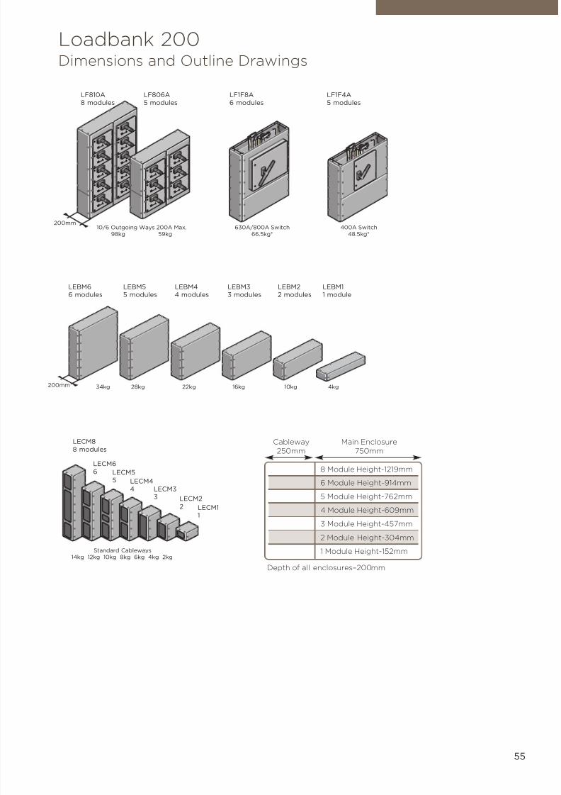
7/21/2019 TE Dorman Smith Product Portofolio 2011
http://slidepdf.com/reader/full/te-dorman-smith-product-portofolio-2011 57/182
55
Loadbank 200Dimensions and Outline Drawings
LEBM66 modules
LEBM55 modules
LEBM44 modules
LEBM33 modules
LEBM22 modules
LEBM11 module
LECM8
8 modules
LECM6
6 LECM55 LECM4
4 LECM3
3 LECM2
2 LECM11
LF810A
8 modules
LF806A
5 modules
LF1F8A
6 modules
LF1F4A
5 modules
8 Module Height-1219mm
6 Module Height-914mm
5 Module Height-762mm
4 Module Height-609mm
3 Module Height-457mm
2 Module Height-304mm
1 Module Height-152mm
Cableway250mm
Main Enclosure750mm
Depth of all enclosures–200mm
Standard Cableways
14kg 12kg 10kg 8kg 6kg 4kg 2kg
400A Switch48.5kg*
630A/800A Switch66.5kg*
34kg 28kg 22kg 16kg 10kg 4kg
10/6 Outgoing Ways 200A Max.98kg 59kg
200mm
200mm
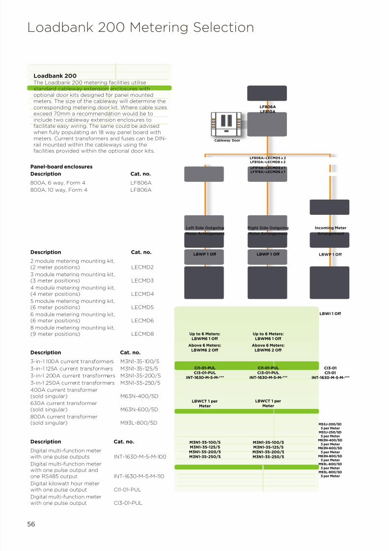
7/21/2019 TE Dorman Smith Product Portofolio 2011
http://slidepdf.com/reader/full/te-dorman-smith-product-portofolio-2011 58/182
56
Loadbank 200 Metering Selection
Panel-board enclosures
Description Cat. no.
800A, 6 way, Form 4 LF806A
800A, 10 way, Form 4 LF806A
Loadbank 200The Loadbank 200 metering facilities utilisestandard cableway extension enclosures with
optional door kits designed for panel mountedmeters. The size of the cableway will determine thecorresponding metering door kit. Where cable sizesexceed 70mm a recommendation would be toinclude two cableway extension enclosures tofacilitate easy wiring. The same could be advisedwhen fully populating an 18 way panel board withmeters. Current transformers and fuses can be DIN-rail mounted within the cableways using thefacilities provided within the optional door kits.
Description Cat. no.
2 module metering mounting kit,(2 meter positions) LECMD2
3 module metering mounting kit,(3 meter positions) LECMD3
4 module metering mounting kit,(4 meter positions) LECMD4
5 module metering mounting kit,(6 meter positions) LECMD5
6 module metering mounting kit,(6 meter positions) LECMD6
8 module metering mounting kit,(9 meter positions) LECMD8
Description Cat. no.
3-in-1 100A current transformers M3N1-35-100/5
3-in-1 125A current transformers M3N1-35-125/5
3-in-1 200A current transformers M3N1-35-200/5
3-in-1 250A current transformers M3N1-35-250/5400A current transformer(sold singular) M63N-400/5D
630A current transformer(sold singular) M63N-600/5D
800A current transformer(sold singular) M93L-800/5D
Description Cat. no.
Digital multi-function meterwith one pulse outputs INT-1630-M-5-M-100
Digital multi-function meterwith one pulse output andone RS485 output INT-1630-M-5-M-110
Digital kilowatt hour meterwith one pulse output CI1-01-PUL
Digital multi-function meterwith one pulse output CI3-01-PUL
Cableway Door
LF806ALF810A
LF806A:-LECMD5 x 2LF810A:-LECMD8 x 2
LF1F4A:-LECMD5 x 1LF1F8A:-LECMD6 x 1
LBWP 1 Off LBWP 1 Off
Left Side Outgoing
Meter Arrangement
Right Side Outgoing
Meter Arrangement
Incoming Meter
Arrangement
LBWI 1 Off
Up to 6 Meters:LBWM6 1 Off
Above 6 Meters:LBWM6 2 Off
Up to 6 Meters:LBWM6 1 Off
Above 6 Meters:LBWM6 2 Off
CI1-01-PULCI3-01-PUL
INT-1630-M-5-M-***
CI1-01-PULCI3-01-PUL
INT-1630-M-5-M-***
CI3-01CI1-01
INT-1630-M-5-M-***
LBWCT 1 perMeter
LBWCT 1 perMeter
M3N1-35-100/5M3N1-35-125/5M3N1-35-200/5M3N1-35-250/5
M3N1-35-100/5M3N1-35-125/5M3N1-35-200/5M3N1-35-250/5
M53J-200/5D3 per Meter
M53J-250/5D3 per Meter
M63N-400/5D3 per Meter
M63N-600/5D3 per Meter
M63N-800/5D3 per Meter
M93L-600/5D3 per Meter
M93L-800/5D3 per Meter
LBWP 1 Off

7/21/2019 TE Dorman Smith Product Portofolio 2011
http://slidepdf.com/reader/full/te-dorman-smith-product-portofolio-2011 59/182
5Section
MCCB Panel Boards
Loadbank 250 Range (400A and 800A Ratings)

7/21/2019 TE Dorman Smith Product Portofolio 2011
http://slidepdf.com/reader/full/te-dorman-smith-product-portofolio-2011 60/182
58
Key Features• ASTA certified busbars with a
short-circuit withstand rating of36kA for 1 second (400A)
• ASTA certified busbars with a
short-circuit rating of 50kA for1 second (800A)• Allows mounting of YA3, Y5, Y6
or Y7 MCCBs and switchdisconnectors
• Single frame size for outgoing16A to 250A MCCBs
• Generous cable-spreadingspace for incoming andoutgoing cables
• Common width (750mm) anddepth (200mm) for allenclosures
Available Options• 400A and 800A panel boards
with 6, 12 or 18 triple-poleoutgoing ways with Y6/Y7 orYA3 incoming devices, withForm 3 separation
• 800A panel boards with 6 or 10TP&N or four-pole outgoingways with fuse switch/MCCBincomer, with Form 4separation
• Panel build options include:
• Range of MCBdistribution boards
• General purposeenclosures with uncut
front plates• Metering housings and
service centres
• Current transformers
• Cableway enclosures
CompliancePanel boards EN 61439-2MCCBs EN 60947-2MCBs EN 60898RCCBs EN 61008RCBOs EN 61009Skeleton Switches 60947-3
Overview
Loadbank 250 modular enclosure system is engineeredto provide unrivalled flexibility and build simplicity
needed to produce a wide range of power distributionsolutions. TP&N busbars of 400A and 800A comprisingof three sizes of 6, 12, 18 TP outgoing ways allowinstallers to cover a multitude of commercial andindustrial applications.
Featuring circuit breakers from 16A to 400A to befitted as outgoing circuits, integral MCB distributionboards, contactors, timers complemented by a newrange of incoming and outgoing metering facilities
completes the Loadbank 250 panel board range.
Loadbank 250 panel boards house the incomer andoutgoing units in separate, adjoining enclosures toallow the widest range of possible circuit permutations,including oversized outgoing circuits, to beaccommodated within a common format. The standardfinish is epoxy powder coating in light grey RAL 7035.
Loadbank 250 single module is 152mm high.

7/21/2019 TE Dorman Smith Product Portofolio 2011
http://slidepdf.com/reader/full/te-dorman-smith-product-portofolio-2011 61/182
59
MCCB Panel Boards (400A and 800A Rating)
Modular Devices
• Surge protection• Meters, current transformers and
wiring looms• Contactors• Timer• Earth leakage device
MCCB Panel Boards
• Service centres
• Cableway extension chambers• General purpose enclosures• TP&N distribution boards
Circuit Protection Devices
• Moulded case circuit breakers (upto 250Aor 400A max)
Incoming Devices
• Switch disconnector• Moulded case circuit breakers• Fuse combination units
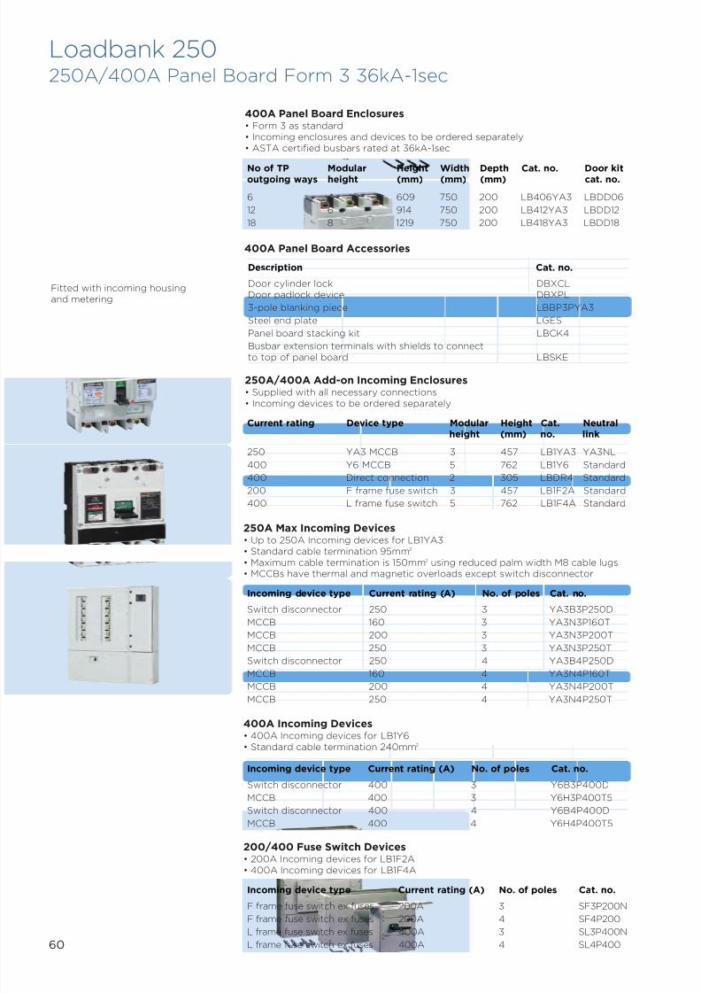
7/21/2019 TE Dorman Smith Product Portofolio 2011
http://slidepdf.com/reader/full/te-dorman-smith-product-portofolio-2011 62/182
60
400A Panel Board Enclosures• Form 3 as standard• Incoming enclosures and devices to be ordered separately• ASTA certified busbars rated at 36kA-1sec
250A/400A Add-on Incoming Enclosures• Supplied with all necessary connections• Incoming devices to be ordered separately
400A Panel Board Accessories
Description Cat. no.
Door cylinder lock DBXCLDoor padlock device DBXPL
3-pole blanking piece LBBP3PYA3
Steel end plate LGES
Panel board stacking kit LBCK4
Busbar extension terminals with shields to connectto top of panel board LBSKE
Current rating Device type Modular Height Cat. Neutralheight (mm) no. link
250 YA3 MCCB 3 457 LB1YA3 YA3NL
400 Y6 MCCB 5 762 LB1Y6 Standard
400 Direct connection 2 305 LBDR4 Standard
200 F frame fuse switch 3 457 LB1F2A Standard
400 L frame fuse switch 5 762 LB1F4A Standard
250A Max Incoming Devices• Up to 250A Incoming devices for LB1YA3• Standard cable termination 95mm2
• Maximum cable termination is 150mm2 using reduced palm width M8 cable lugs• MCCBs have thermal and magnetic overloads except switch disconnector
Incoming device type Current rating (A) No. of poles Cat. no.
Switch disconnector 250 3 YA3B3P250D
MCCB 160 3 YA3N3P160T
MCCB 200 3 YA3N3P200T
MCCB 250 3 YA3N3P250T
Switch disconnector 250 4 YA3B4P250D
MCCB 160 4 YA3N4P160T
MCCB 200 4 YA3N4P200T
MCCB 250 4 YA3N4P250T
No of TP Modular Height Width Depth Cat. no. Door kitoutgoing ways height (mm) (mm) (mm) cat. no.
6 4 609 750 200 LB406YA3 LBDD06
12 6 914 750 200 LB412YA3 LBDD12
18 8 1219 750 200 LB418YA3 LBDD18
400A Incoming Devices• 400A Incoming devices for LB1Y6• Standard cable termination 240mm2
200/400 Fuse Switch Devices• 200A Incoming devices for LB1F2A
• 400A Incoming devices for LB1F4A
Incoming device type Current rating (A) No. of poles Cat. no.
Switch disconnector 400 3 Y6B3P400D
MCCB 400 3 Y6H3P400T5
Switch disconnector 400 4 Y6B4P400D
MCCB 400 4 Y6H4P400T5
Incoming device type Current rating (A) No. of poles Cat. no.
F frame fuse switch ex fuses 200A 3 SF3P200N
F frame fuse switch ex fuses 200A 4 SF4P200
L frame fuse switch ex fuses 400A 3 SL3P400N
L frame fuse switch ex fuses 400A 4 SL4P400
Loadbank 250250A/400A Panel Board Form 3 36kA-1sec
Fitted with incoming housingand metering
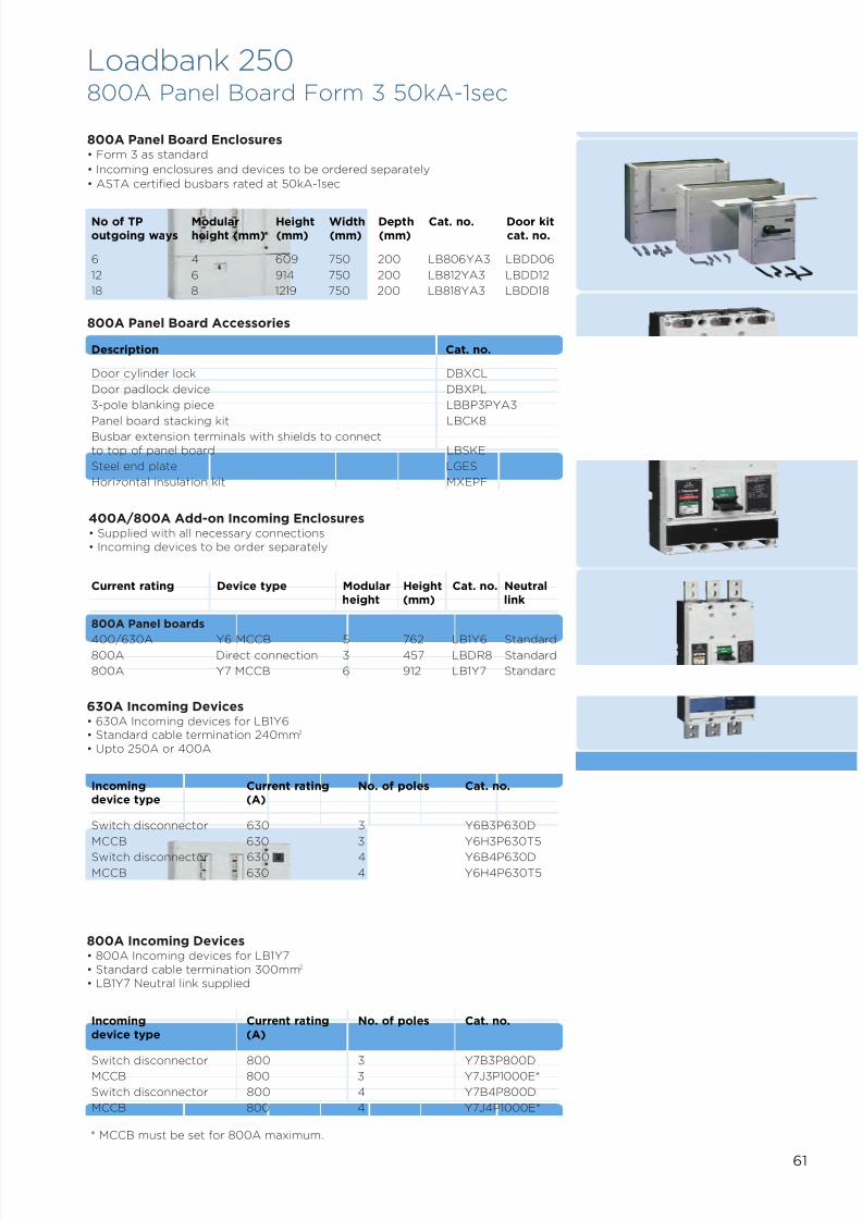
7/21/2019 TE Dorman Smith Product Portofolio 2011
http://slidepdf.com/reader/full/te-dorman-smith-product-portofolio-2011 63/182
61
* MCCB must be set for 800A maximum.
Loadbank 250800A Panel Board Form 3 50kA-1sec
630A Incoming Devices• 630A Incoming devices for LB1Y6• Standard cable termination 240mm2
• Upto 250A or 400A
Incoming Current rating No. of poles Cat. no.device type (A)
Switch disconnector 630 3 Y6B3P630D
MCCB 630 3 Y6H3P630T5
Switch disconnector 630 4 Y6B4P630D
MCCB 630 4 Y6H4P630T5
800A Incoming Devices• 800A Incoming devices for LB1Y7• Standard cable termination 300mm2
• LB1Y7 Neutral link supplied
Incoming Current rating No. of poles Cat. no.device type (A)
Switch disconnector 800 3 Y7B3P800DMCCB 800 3 Y7J3P1000E*
Switch disconnector 800 4 Y7B4P800D
MCCB 800 4 Y7J4P1000E*
No of TP Modular Height Width Depth Cat. no. Door kitoutgoing ways height (mm) (mm) (mm) (mm) cat. no.
6 4 609 750 200 LB806YA3 LBDD06
12 6 914 750 200 LB812YA3 LBDD12
18 8 1219 750 200 LB818YA3 LBDD18
800A Panel Board Enclosures• Form 3 as standard
• Incoming enclosures and devices to be ordered separately
• ASTA certified busbars rated at 50kA-1sec
400A/800A Add-on Incoming Enclosures• Supplied with all necessary connections• Incoming devices to be order separately
Current rating Device type Modular Height Cat. no. Neutralheight (mm) link
800A Panel boards
400/630A Y6 MCCB 5 762 LB1Y6 Standard800A Direct connection 3 457 LBDR8 Standard
800A Y7 MCCB 6 912 LB1Y7 Standard
800A Panel Board Accessories
Description Cat. no.
Door cylinder lock DBXCL
Door padlock device DBXPL
3-pole blanking piece LBBP3PYA3
Panel board stacking kit LBCK8Busbar extension terminals with shields to connectto top of panel board LBSKE
Steel end plate LGES
Horizontal insulation kit MXEPF
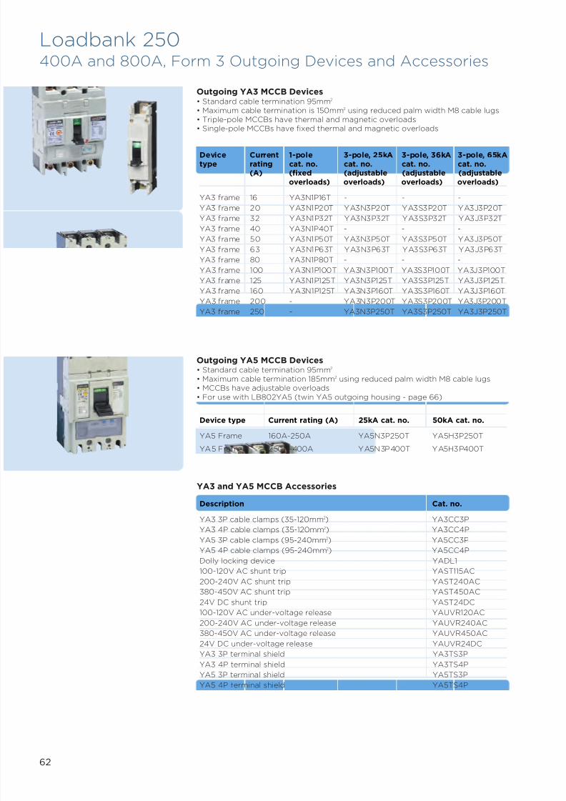
7/21/2019 TE Dorman Smith Product Portofolio 2011
http://slidepdf.com/reader/full/te-dorman-smith-product-portofolio-2011 64/182
62
Outgoing YA3 MCCB Devices• Standard cable termination 95mm2
• Maximum cable termination is 150mm2 using reduced palm width M8 cable lugs• Triple-pole MCCBs have thermal and magnetic overloads• Single-pole MCCBs have fixed thermal and magnetic overloads
Device Current 1-pole 3-pole, 25kA 3-pole, 36kA 3-pole, 65kAtype rating cat. no. cat. no. cat. no. cat. no.
(A) (fixed (adjustable (adjustable (adjustableoverloads) overloads) overloads) overloads)
YA3 frame 16 YA3N1P16T - - -
YA3 frame 20 YA3N1P20T YA3N3P20T YA3S3P20T YA3J3P20T
YA3 frame 32 YA3N1P32T YA3N3P32T YA3S3P32T YA3J3P32T
YA3 frame 40 YA3N1P40T - - -
YA3 frame 50 YA3N1P50T YA3N3P50T YA3S3P50T YA3J3P50T
YA3 frame 63 YA3N1P63T YA3N3P63T YA3S3P63T YA3J3P63T
YA3 frame 80 YA3N1P80T - - -
YA3 frame 100 YA3N1P100T YA3N3P100T YA3S3P100T YA3J3P100T
YA3 frame 125 YA3N1P125T YA3N3P125T YA3S3P125T YA3J3P125TYA3 frame 160 YA3N1P125T YA3N3P160T YA3S3P160T YA3J3P160T
YA3 frame 200 - YA3N3P200T YA3S3P200T YA3J3P200T
YA3 frame 250 - YA3N3P250T YA3S3P250T YA3J3P250T
Outgoing YA5 MCCB Devices• Standard cable termination 95mm2
• Maximum cable termination 185mm2 using reduced palm width M8 cable lugs• MCCBs have adjustable overloads• For use with LB802YA5 (twin YA5 outgoing housing - page 66)
Description Cat. no.
YA3 3P cable clamps (35-120mm2) YA3CC3P
YA3 4P cable clamps (35-120mm2) YA3CC4P
YA5 3P cable clamps (95-240mm2) YA5CC3P
YA5 4P cable clamps (95-240mm2) YA5CC4P
Dolly locking device YADL1100-120V AC shunt trip YAST115AC
200-240V AC shunt trip YAST240AC
380-450V AC shunt trip YAST450AC
24V DC shunt trip YAST24DC
100-120V AC under-voltage release YAUVR120AC
200-240V AC under-voltage release YAUVR240AC
380-450V AC under-voltage release YAUVR450AC
24V DC under-voltage release YAUVR24DC
YA3 3P terminal shield YA3TS3P
YA3 4P terminal shield YA3TS4P
YA5 3P terminal shield YA5TS3P
YA5 4P terminal shield YA5TS4P
YA3 and YA5 MCCB Accessories
Device type Current rating (A) 25kA cat. no. 50kA cat. no.
YA5 Frame 160A-250A YA5N3P250T YA5H3P250T
YA5 Frame 250A-400A YA5N3P400T YA5H3P400T
Loadbank 250400A and 800A, Form 3 Outgoing Devices and Accessories
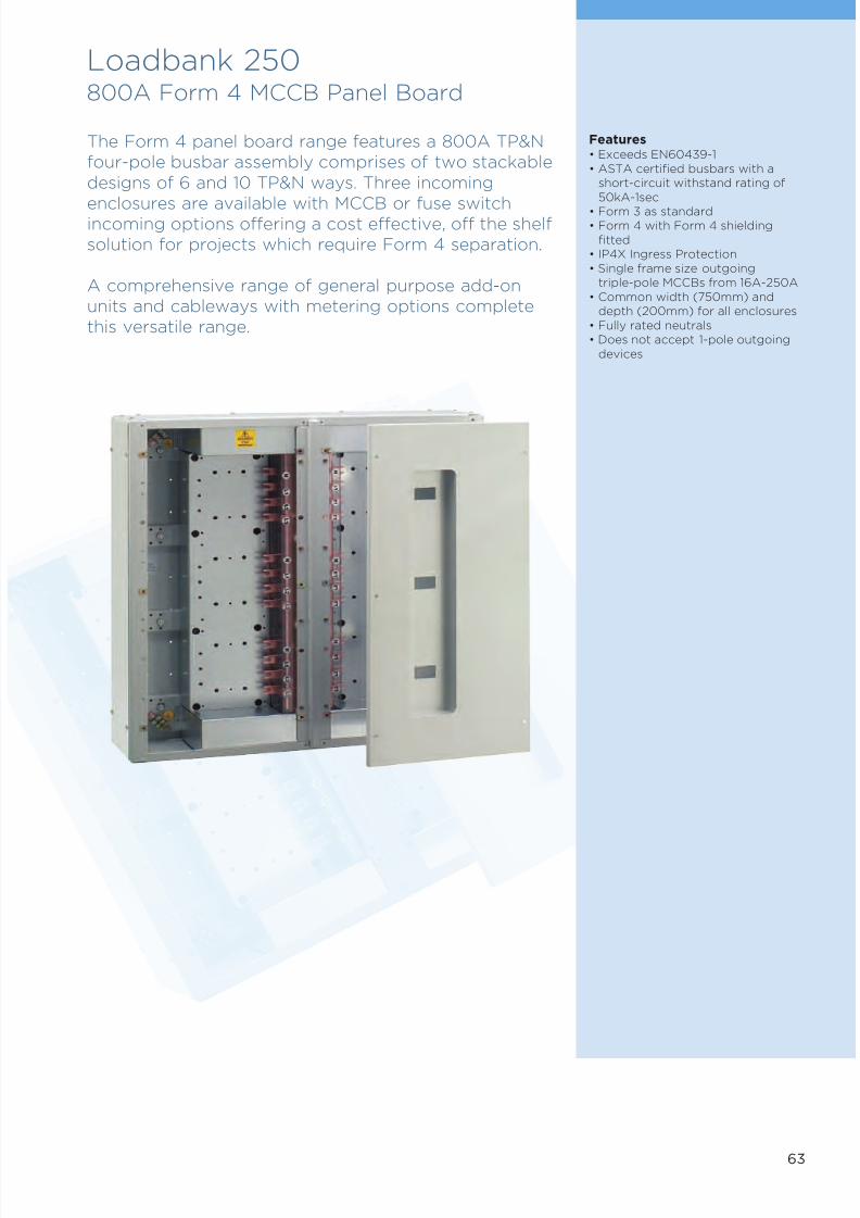
7/21/2019 TE Dorman Smith Product Portofolio 2011
http://slidepdf.com/reader/full/te-dorman-smith-product-portofolio-2011 65/182
Loadbank 250800A Form 4 MCCB Panel Board
63
The Form 4 panel board range features a 800A TP&Nfour-pole busbar assembly comprises of two stackable
designs of 6 and 10 TP&N ways. Three incomingenclosures are available with MCCB or fuse switchincoming options offering a cost effective, off the shelfsolution for projects which require Form 4 separation.
A comprehensive range of general purpose add-onunits and cableways with metering options completethis versatile range.
Features• Exceeds EN60439-1• ASTA certified busbars with a
short-circuit withstand rating of50kA-1sec
• Form 3 as standard• Form 4 with Form 4 shielding
fitted• IP4X Ingress Protection• Single frame size outgoing
triple-pole MCCBs from 16A-250A• Common width (750mm) and
depth (200mm) for all enclosures• Fully rated neutrals• Does not accept 1-pole outgoing
devices

7/21/2019 TE Dorman Smith Product Portofolio 2011
http://slidepdf.com/reader/full/te-dorman-smith-product-portofolio-2011 66/182
64
800A Panel Boards - Form 4• No provision for 1-pole MCCBs• Form 3 as standard• Form 4 with optional shielding• IP3X (IP4X with door kit fitted) Ingress Protection
• 750mm wide x 200mm deep• Spare busbar terminal covers/blanking plates are to be ordered separately
Add-on Incoming Enclosures• Form 4 as standard• IP4X Ingress Protection
No of TP Modular Height Weight Cat. no. Optionaloutgoing ways height (mm) (kg) door kit
6 5 760 59 LF806YA MXD06
10 8 1216 98 LF810YA MXD10
Description Cat. no.
Form 4 shielding for cable up to 70mm2 LFS41YA
Form 4 shielding for outgoing cables to 150mm2 LFS42YA
Vertical stacking connection kit LCFVKBlanking plate for unused way YA3F4BP
Current Modular Height Weight Device Cat. no. Connectionrating height (mm) (kg) type kit required(A)
400 5 762 98 L frame fuse LF1F4A -switch
630/800 8 1216 66.5 N frame fuse LF1F8A -switch
400-800 5 762 45.2 Y6 MCCB/ MMS15Y* MCFMY6MCCB switchdisconnector
400A Fuse Switch Incoming Devices• 400A Incoming devices for LF1F4A enclosure
• Standard cable termination 240mm2
Incoming device type Current rating (A) No. of poles Cat. no.
L frame fuse switch 400 TP&N SL3P400N
L frame fuse switch 400 4 SL4P400N
800A Panel Board Accessories
Loadbank 250800A Panel Board Form 4 50kA-1sec
*Neutral link supplied

7/21/2019 TE Dorman Smith Product Portofolio 2011
http://slidepdf.com/reader/full/te-dorman-smith-product-portofolio-2011 67/182
65
Incoming Current No. of Max cable Cat. no.device type rating (A) poles termination
(mm2)
Y6 frame switch disconnector 400 3 240 Y6B3P400D
Y6 frame MCCB 400 3 240 Y6H3P400T5
Y6 frame MCCB 630 3 240 Y6H3P630T5
Y6 frame MCCB 800 3 240 Y6H3P800T5
Y6 frame switch disconnector 400 4 240 Y6B4P400D
Y6 frame MCCB 400 4 240 Y6H4P400T5Y6 frame MCCB 630 4 240 Y6H4P630T5
Y6 frame MCCB 800 4 240 Y6H4P800T5
Incoming Current No. of Max cable Cat. no. Cabledevice type rating poles termination terminals
(A) (mm2)
N frame fuse switch 630 TP&N 630 SN3P630N SNCET
N frame fuse switch 800 TP&N 630 SN3P800N SNCET
N frame fuse switch 630 4 630 SN4P630N SNCET
N frame fuse switch 800 4 630 SN4P800N SNCET
630A/800A Fuse Switch Incoming Devices• 630A/800A Incoming devices for LF1F8A enclosure• Standard cable termination 630mm2
Incoming MCCB Devices
• 400A-800A Incoming devices for MMS15Y enclosure• Standard cable termination 240mm2
• Triple-pole and four-pole MCCBs have adjustable thermal and magneticoverloads
Outgoing MCCB Devices• Standard cable termination 95mm2
• Maximum cable termination is 150mm2 using reduced palm width M8 cable lugs• Triple-pole MCCBs have adjustable thermal and magnetic overloads
Device type Current 3-pole, 25kA 3-pole, 36kA 3-pole, 65kArating (A) cat. no. cat. no. cat. no.
(adjustable (adjustable (adjustableoverloads) overloads) overloads)
YA3 frame 16 - - -
YA3 frame 20 YA3N3P20T YA3S3P20T YA3J3P20T
YA3 frame 32 YA3N3P32T YA3S3P32T YA3J3P32T
YA3 frame 40 - - -
YA3 frame 50 YA3N3P50T YA3S3P50T YA3J3P50T
YA3 frame 63 YA3N3P63T YA3S3P63T YA3J3P63T
YA3 frame 80 - - -
YA3 frame 100 YA3N3P100T YA3S3P100T YA3J3P100T
YA3 frame 125 YA3N3P125T YA3S3P125T YA3J3P125T
YA3 frame 160 YA3N3P160T YA3S3P160T YA3J3P160T
YA3 frame 200 YA3N3P200T YA3S3P200T YA3J3P200T
YA3 frame 250 YA3N3P250T YA3S3P250T YA3J3P250T
Loadbank 250800A Panel Board Incoming and Outgoing Devices

7/21/2019 TE Dorman Smith Product Portofolio 2011
http://slidepdf.com/reader/full/te-dorman-smith-product-portofolio-2011 68/182
66
General Purpose Enclosures• IP4X Ingress Protection• Enclosures are 750mm wide x 200 deep• No top or bottom plates supplied (supplied with panel board)
Description Modular height Height (mm) Cat. no.
General purpose enclosure 1 152 LEBM1
General purpose enclosure 2 305 LEBM2
General purpose enclosure 3 457 LEBM3
General purpose enclosure 4 609 LEBM4
General purpose enclosure 5 762 LEBM5
General purpose enclosure 6 914 LEBM6
Cableway Extension Enclosures
• IP4X Ingress Protection• Recommend for cables above 70mm2
• 250mm wide x 200mm deep• No side plates supplied (supplied with panel board)
Description Modular height Height (mm) Cat. no.
Cableway 1 152 LECM1
Cableway 2 305 LECM2
Cableway 3 457 LECM3
Cableway 4 609 LECM4
Cableway 5 762 LECM5
Cableway 6 914 LECM6
Cableway 8 1219 LECM8
MCB Distribution Board and Service Centre• IP3X (IP4X with door fitted) Ingress Protection• MCB distribution boards have fully shielded busbars and interconnections• Space saving twin option TP&N distribution board option
*Only double module RCBOs can be fitted in this enclosure.
Description Modular Height Cat. no. Door kitheight (mm) cat. no.
17 MCB way SP&N distribution board 1 152 LDS17 LD1DS
6 TP way TP&N distribution board 2 305 LDT106X LD1D06X
12 TP way TP&N distribution board 3 457 LDT112X LD1D12X
2 x 12 TP way TP&N distribution board 4 609 LDT212X* LD2D12X24 way modular service centre 1 152 LDS24 LD1DS
Twin YA5 Outgoing Housing (not design for use with Form 4 panelboards)• Can be mounted direct to incoming enclosure without connection kit• When mounting to 800A panelboard connection kits are required
(LBSKE and LBCK8)• Cableway extension enclosures are necessary to assist with cabling• Terminal shields required per MCCB (YA5TC3P)• Devices to be ordered separately (page 62)
Description Modular Height Weight Cat. no. Door kitheight (mm) (kg) cat. no.
Twin YA5 (400A max each) 3 modules 456 35 LB802YA5 LBDD02
Loadbank 250400A and 800A, Form 3 and 4, Panel Board Add-on Enclosures
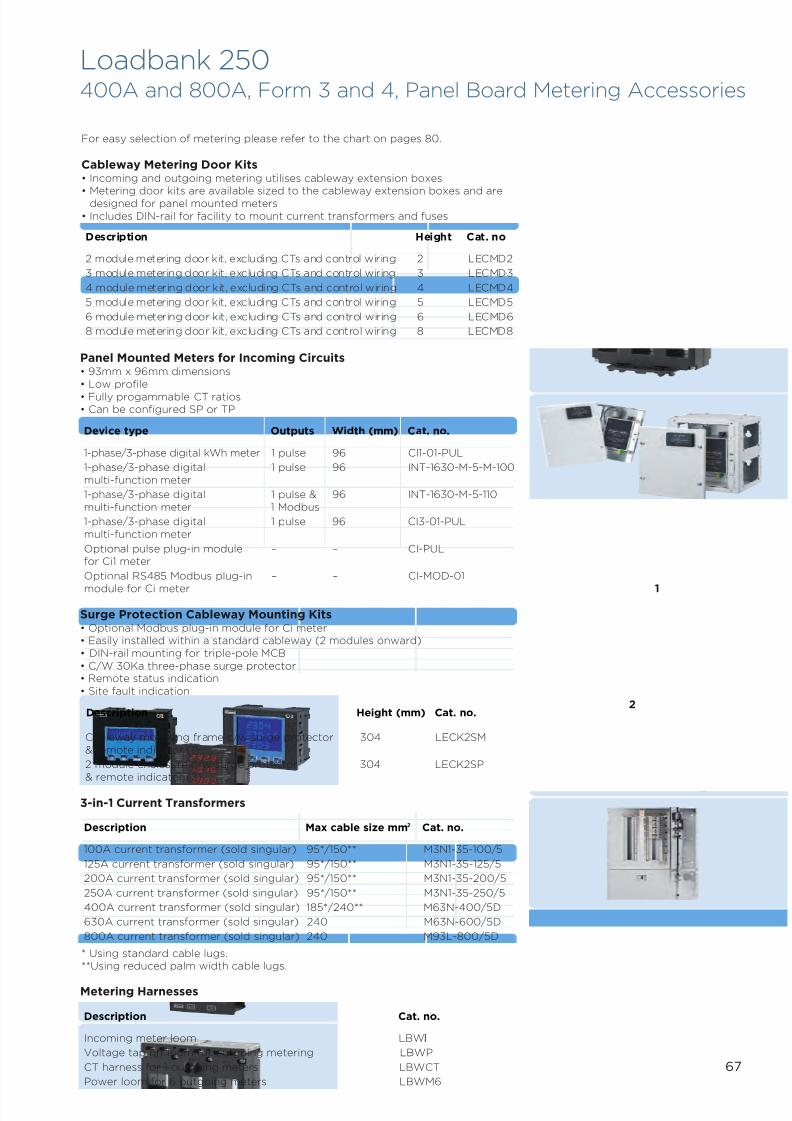
7/21/2019 TE Dorman Smith Product Portofolio 2011
http://slidepdf.com/reader/full/te-dorman-smith-product-portofolio-2011 69/182
67
Loadbank 250400A and 800A, Form 3 and 4, Panel Board Metering Accessories
Description Height Cat. no
2 module metering door kit, excluding CTs and control wiring 2 LECMD2
3 module metering door kit, excluding CTs and control wiring 3 LECMD3
4 module metering door kit, excluding CTs and control wiring 4 LECMD4
5 module metering door kit, excluding CTs and control wiring 5 LECMD5
6 module metering door kit, excluding CTs and control wiring 6 LECMD6
8 module metering door kit, excluding CTs and control wiring 8 LECMD8
* Using standard cable lugs.**Using reduced palm width cable lugs.
For easy selection of metering please refer to the chart on pages 80.
Cableway Metering Door Kits• Incoming and outgoing metering utilises cableway extension boxes
• Metering door kits are available sized to the cableway extension boxes and aredesigned for panel mounted meters• Includes DIN-rail for facility to mount current transformers and fuses
Device type Outputs Width (mm) Cat. no.
1-phase/3-phase digital kWh meter 1 pulse 96 CI1-01-PUL
1-phase/3-phase digital 1 pulse 96 INT-1630-M-5-M-100multi-function meter
1-phase/3-phase digital 1 pulse & 96 INT-1630-M-5-110multi-function meter 1 Modbus
1-phase/3-phase digital 1 pulse 96 CI3-01-PULmulti-function meter
Optional pulse plug-in module – – CI-PULfor Ci1 meter
Optional RS485 Modbus plug-in – – CI-MOD-01
module for Ci meter
Description Cat. no.
Incoming meter loom LBWI
Voltage tap off loom for outgoing metering LBWP
CT harness for 1 outgoing meters LBWCT
Power loom for 6 outgoing meters LBWM6
Metering Harnesses
Description Max cable size mm2 Cat. no.
100A current transformer (sold singular) 95*/150** M3N1-35-100/5
125A current transformer (sold singular) 95*/150** M3N1-35-125/5
200A current transformer (sold singular) 95*/150** M3N1-35-200/5
250A current transformer (sold singular) 95*/150** M3N1-35-250/5
400A current transformer (sold singular) 185*/240** M63N-400/5D
630A current transformer (sold singular) 240 M63N-600/5D
800A current transformer (sold singular) 240 M93L-800/5D
3-in-1 Current Transformers
Panel Mounted Meters for Incoming Circuits• 93mm x 96mm dimensions• Low profile• Fully progammable CT ratios• Can be configured SP or TP
Surge Protection Cableway Mounting Kits• Optional Modbus plug-in module for Ci meter• Easily installed within a standard cableway (2 modules onward)• DIN-rail mounting for triple-pole MCB• C/W 30Ka three-phase surge protector• Remote status indication• Site fault indication
Cableway mounting frame c/w surge protector 304 LECK2SM& remote indicator (1)
2 module enclosure c/w surge protector 304 LECK2SP
& remote indicator (2)
Description Height (mm) Cat. no.
1
2
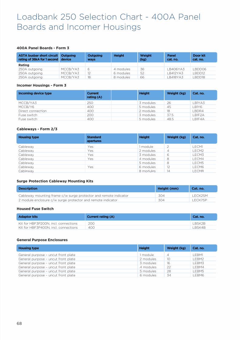
7/21/2019 TE Dorman Smith Product Portofolio 2011
http://slidepdf.com/reader/full/te-dorman-smith-product-portofolio-2011 70/182
68
Loadbank 250 Selection Chart - 400A PanelBoards and Incomer Housings
400A Panel Boards - Form 3
Incomer Housings - Form 3
Incoming device type Current Height Weight (kg) Cat. no.rating (A)
MCCB/YA3 250 3 modules 26 LB1YA3
MCCB/Y6 400 5 modules 45 LB1Y6
Direct connection 400 2 modules 18 LBDR4
Fuse switch 200 3 modules 37.5 LB1F2A
Fuse switch 400 5 modules 48.5 LB1F4A
Housed Fuse Switch
Adaptor kits Current rating (A) Cat. no.
Kit for HBF3P200N, incl. connections 200 LBSK2B
Kit for HBF3P400N, incl. connections 400 LBSK4B
Cableways - Form 2/3
Housing type Standard Height Weight (kg) Cat. no.apertures
Cableway Yes 1 module 2 LECM1
Cableway Yes 2 modules 4 LECM2
Cableway Yes 3 modules 6 LECM3
Cableway Yes 4 modules 8 LECM4
Cableway 5 modules 8 LECM5
Cableway Yes 6 modules 12 LECM6
Cableway 8 modules 14 LECM8
General Purpose Enclosures
Housing type Height Weight (kg) Cat. no.
General purpose – uncut front plate 1 module 4 LEBM1
General purpose – uncut front plate 2 modules 10 LEBM2
General purpose – uncut front plate 3 modules 16 LEBM3
General purpose – uncut front plate 4 modules 22 LEBM4
General purpose – uncut front plate 5 modules 28 LEBM5
General purpose – uncut front plate 6 modules 34 LEBM6
Surge Protection Cableway Mounting Kits
Description Height (mm) Cat. no.
Cableway mounting frame c/w surge protector and remote indicator 304 LECK2SM
2 module enclosure c/w surge protector and remote indicator 304 LECK2SP
ASTA busbar short circuit Outgoing Outgoing Height Weight Panel Door kit
rating of 36kA for 1 second device ways (kg) cat. no. cat. no.
Rating
250A outgoing MCCB/YA3 6 4 modules 36 LB406YA3 LBDD06
250A outgoing MCCB/YA3 12 6 modules 52 LB412YA3 LBDD12
250A outgoing MCCB/YA3 18 8 modules 66 LB418YA3 LBDD18
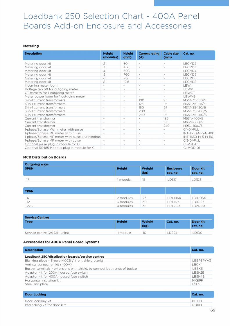
7/21/2019 TE Dorman Smith Product Portofolio 2011
http://slidepdf.com/reader/full/te-dorman-smith-product-portofolio-2011 71/182
69
Metering
Description Height Height Current rating Cable size Cat. no.
(modules) (mm) (A) (mm)
Metering door kit 2 304 - - LECMD2Metering door kit 3 456 - - LECMD3Metering door kit 4 608 - - LECMD4Metering door kit 5 760 - - LECMD5Metering door kit 6 912 - - LECMD6Metering door kit 8 1216 - - LECMD8Incoming meter loom - - - - LBWIVoltage tap off for outgoing meter - - - - LBWPCT harness for 1 outgoing meter - - - - LBWCTMeter power loom for 1 outgoing meter - - - - LBWM63-in-1 current transformers - - 100 95 M3N1-35-100/53-in-1 current transformers - - 125 95 M3N1-35-125/53-in-1 current transformers - - 150 95 M3N1-35-150/53-in-1 current transformers - - 200 95 M3N1-35-200/5
3-in-1 current transformers - - 250 95 M3N1-35-250/5Current transformer - - - 185 M63N-400/5Current transformer - - - 185 M63N-600/5Current transformer - - - 240 M93L-800/51-phase/3phase kWh meter with pulse - - - - CI1-01-PUL1-phase/3phase MF meter with pulse - - - - INT-1630-M-5-M-1001-phase/3phase MF meter with pulse and Modbus - - - - INT-1630-M-5-M-1101-phase/3phase MF meter with pulse - - - - CI3-01-PULOptional pulse plug in module for Ci - - - - CI-PUL-01Optional RS485 Modbus plug in module for Ci - - - - CI-MOD-01
Loadbank 250 Selection Chart - 400A PanelBoards Add-on Enclosure and Accessories
Outgoing ways
SP&N Height Weight Enclosure Door kit
(kg) cat. no. cat. no.
17 1 module 15 LDS17 LD1DS
Service Centres
Type Height Weight Cat. no. Door kit
(kg) cat. no.
Service centre (24 DIN units) 1 module 10 LDS24 LD1DS
TP&N
6 2 modules 23 LDT106X LD1D06X
12 3 modules 30 LDT112X LD1D12X
2x12 4 modules 35 LDT212X LD2D12X
Description Cat. no.
Loadbank 250/distribution boards/service centres
Blanking piece – 3-pole MCCB (1 front shield blank) LBBP3PYA3
Vertical connection kit (400A) LBCK4
Busbar terminals - extensions with shield, to connect both ends of busbar LBSKE
Adaptor kit for 200A housed fuse switch LBSK2B
Adaptor kit for 400A housed fuse switch LBSK4B
Horizontal insulation kit MXEPF
Steel end plate LGES
MCB Distribution Boards
Door Locking Cat. no.
Door lock/key kit DBXCL
Padlocking kit for door kits DBXPL
Accessories for 400A Panel Board Systems
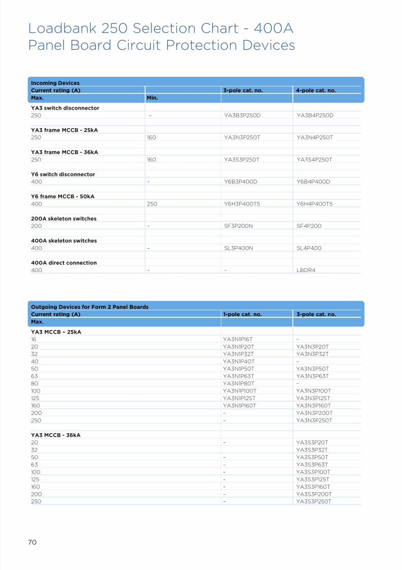
7/21/2019 TE Dorman Smith Product Portofolio 2011
http://slidepdf.com/reader/full/te-dorman-smith-product-portofolio-2011 72/182
Loadbank 250 Selection Chart - 400APanel Board Circuit Protection Devices
Incoming Devices
Current rating (A) 3-pole cat. no. 4-pole cat. no.
Max. Min.YA3 switch disconnector
250 – YA3B3P250D YA3B4P250D
YA3 frame MCCB - 25kA
250 160 YA3N3P250T YA3N4P250T
YA3 frame MCCB - 36kA
250 160 YA3S3P250T YA3S4P250T
Y6 switch disconnector
400 – Y6B3P400D Y6B4P400D
Y6 frame MCCB - 50kA400 250 Y6H3P400T5 Y6H4P400T5
200A skeleton switches
200 – SF3P200N SF4P200
400A skeleton switches
400 – SL3P400N SL4P400
400A direct connection
400 – – LBDR4
Outgoing Devices for Form 2 Panel Boards
Current rating (A) 1-pole cat. no. 3-pole cat. no.
Max.
YA3 MCCB – 25kA
16 YA3N1P16T –
20 YA3N1P20T YA3N3P20T
32 YA3N1P32T YA3N3P32T
40 YA3N1P40T –
50 YA3N1P50T YA3N3P50T
63 YA3N1P63T YA3N3P63T
80 YA3N1P80T –
100 YA3N1P100T YA3N3P100T
125 YA3N1P125T YA3N3P125T160 YA3N1P160T YA3N3P160T
200 – YA3N3P200T
250 – YA3N3P250T
YA3 MCCB - 36kA
20 – YA3S3P20T
32 – YA3S3P32T
50 – YA3S3P50T
63 – YA3S3P63T
100 – YA3S3P100T
125 – YA3S3P125T
160 – YA3S3P160T
200 – YA3S3P200T
250 – YA3S3P250T
70

7/21/2019 TE Dorman Smith Product Portofolio 2011
http://slidepdf.com/reader/full/te-dorman-smith-product-portofolio-2011 73/182
71
Loadbank 250 Selection Chart - 400A PanelBoard and Incoming Devices Accessories
Description Cat. no.
Solid links (set of 1) HLL400
Terminal barriers (set of 3) SLTB
Fuse shrouds SLFS
Terminal shrouds and barriers SLTS
2-blank auxiliary switch SAUX2N
4-blank auxiliary switch SAUX4N
6-blank auxiliary switch SAUX6N
Y6 Frame Accessories
Description Cat. no.
Terminal covers 3-poleInterphase barriers (set of 2) Y5TB3P
Terminal covers 4-pole
Interphase barriers (set of 3) Y5TB4P
Terminations 4-pole
Extension terminal bars Y6XT4P
Locking devices
Dolly padlock device Y6DL
Shunt trips
Shunt 100-115V AC Y6ST115AC
Shunt 200-450V AC Y6ST450AC
Shunt 24V DC Y6ST24DC
Under-voltage release
UVR 100-120V AC Y6UVR120AC
UVR 200-240V AC Y6UVR240AC
UVR 380-450V AC Y6UVR450AC
UVR 24V DC Y6UVR24DC
Auxiliary switches
1AB auxiliary switch Y6AUX1
2AB auxiliary switch Y6AUX2
Alarm switch + 1 auxiliary Y6AUXAL
Accessories for 400A Skeleton Switches
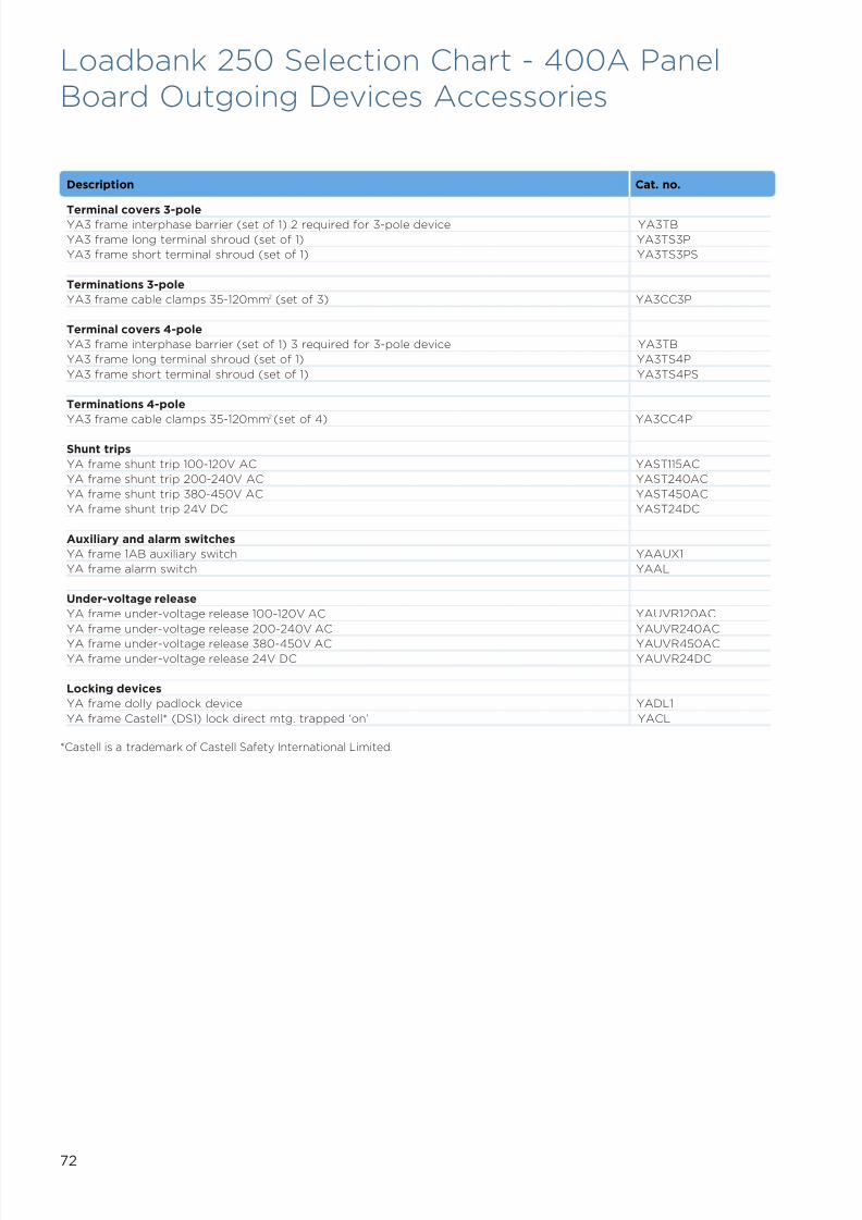
7/21/2019 TE Dorman Smith Product Portofolio 2011
http://slidepdf.com/reader/full/te-dorman-smith-product-portofolio-2011 74/182
72
Loadbank 250 Selection Chart - 400A PanelBoard Outgoing Devices Accessories
Description Cat. no.
Terminal covers 3-poleYA3 frame interphase barrier (set of 1) 2 required for 3-pole device YA3TB
YA3 frame long terminal shroud (set of 1) YA3TS3P
YA3 frame short terminal shroud (set of 1) YA3TS3PS
Terminations 3-pole
YA3 frame cable clamps 35-120mm2 (set of 3) YA3CC3P
Terminal covers 4-pole
YA3 frame interphase barrier (set of 1) 3 required for 3-pole device YA3TB
YA3 frame long terminal shroud (set of 1) YA3TS4P
YA3 frame short terminal shroud (set of 1) YA3TS4PS
Terminations 4-pole
YA3 frame cable clamps 35-120mm2 (set of 4) YA3CC4P
Shunt trips
YA frame shunt trip 100-120V AC YAST115AC
YA frame shunt trip 200-240V AC YAST240AC
YA frame shunt trip 380-450V AC YAST450AC
YA frame shunt trip 24V DC YAST24DC
Auxiliary and alarm switches
YA frame 1AB auxiliary switch YAAUX1
YA frame alarm switch YAAL
Under-voltage release
YA frame under-voltage release 100-120V AC YAUVR120AC
YA frame under-voltage release 200-240V AC YAUVR240AC
YA frame under-voltage release 380-450V AC YAUVR450AC
YA frame under-voltage release 24V DC YAUVR24DC
Locking devices
YA frame dolly padlock device YADL1
YA frame Castell* (DS1) lock direct mtg. trapped ‘on’ YACL
*Castell is a trademark of Castell Safety International Limited.

7/21/2019 TE Dorman Smith Product Portofolio 2011
http://slidepdf.com/reader/full/te-dorman-smith-product-portofolio-2011 75/182
73
800A Panel Boards – Form 3
ASTA busbar short circuit rating Outgoing Outgoing Height Weight Panel Door kit
of 50kA for 1 second device ways (kg) cat. no. cat no.
250A outgoing MCCB/YA3 6 4 modules 42 LB806YA3 LBDD06
250A outgoing MCCB/YA3 12 6 modules 62 LB812YA3 LBDD12
250A outgoing MCCB/YA3 18 8 modules 78 LB818YA3 LBDD18
800A Panel Boards – Form 4
ASTA busbar short circuit rating Outgoing Outgoing Height Weight Panel Door kit
of 50kA for 1 second device ways (kg) cat. no. cat no.
250A outgoing MCCB/YA3 6 5 modules 59 LF806YA MXD06
250A outgoing MCCB/YA3 10 8 modules 98 LF810YA MXD10
Incomer Housings – Form 3
Incomer device type Current Height Weight Cat. no.
rating (A) (kg)
MCCB/Y6 630 5 modules 45 LB1Y6
MCCB/Y7 800 6 modules 69 LB1Y7
Direct connection 800 3 modules 23 LBDR8
Outgoing Housings – Form 3
Incomer device type Current Outgoing Height Weight Panel Door kit
rating (A) ways (kg) cat. no. cat. no.
2x YA5 MCCB 400 2 3 modules 25 LB802YA5 LBDD02
Incomer Housings – Form 4
Device type housing Current Height Weight Cat. no.
rating (A) (kg)
Fuse switch 630/800 6 modules 67 LF1F8A
Y6 frame MCCB 800 5 modules 59 MMS15Y
Y6 connection kit MCFMY6
Shielding – Form 4
Description Additional Cat. no.
housing
70mm2 cables LFS41YA
150mm2 cables Cableway LFS42YA
Loadbank 250 Selection Chart - 800A PanelBoards and Incomer Housings
Description Height (mm) Cat. no.
Cableway mounting frame c/w surge protector and remote indicator 304 LECK2SM2 module enclosure c/w surge protector and remote indicator 304 LECK2SP
Surge Protection Cableway Mounting Kits

7/21/2019 TE Dorman Smith Product Portofolio 2011
http://slidepdf.com/reader/full/te-dorman-smith-product-portofolio-2011 76/182
74
Loadbank 250 Selection Chart - 800A PanelBoards Add-on Enclosures and Accessories
Metering
Description Height Height Current rating Cable size Cat. no.
(modules) (mm) (A) (mm)
Metering door kit 2 304 - - LECMD2Metering door kit 3 456 - - LECMD3Metering door kit 4 608 - - LECMD4Metering door kit 5 760 - - LECMD5Metering door kit 6 912 - - LECMD6Metering door kit 8 1216 - - LECMD8Incoming meter loom - - - - LBWIVoltage tap off for outgoing meter - - - - LBWPCT harness for 1 outgoing meter - - - - LBWCTMeter power loom for 1 outgoing meter - - - - LBWM63-in-1 current transformers - - 100 95 M3N1-35-100/53-in-1 current transformers - - 125 95 M3N1-35-100/53-in-1 current transformers - - 150 95 M3N1-35-100/53-in-1 current transformers - - 200 95 M3N1-35-100/5
3-in-1 current transformers - - 250 95 M3N1-35-100/5Current transformer - - - 185 M63N-400/5Current transformer - - - 185 M63N-600/5Current transformer - - - 240 M93L-800/51-phase/3phase kWh meter with pulse output - - - - CI1-01-PUL1-phase/3phase MF meter with pulse output - - - - INT-1630-M-5-M-1001-phase/3phase MF meter with pulse - - - - INT-1630-M-5-M-110and Modbus output1-phase/3phase MF meter with pulse output - - - - CI3-01-PULOptional pulse plug in module for Ci meter - - - - CI-PUL-01Optional RS485 Modbus plug in module for - - - - CI-MOD-01Ci meter -
Outgoing waysSP&N Height Weight Enclosure Door kit
(kg) cat. no. cat. no.
17 1 module 15 LDS17 LD1DS
Description Cat. no.
Loadbank 250/distribution boards/service centres
Blanking piece – 3-pole MCCB (1 front shield blank) LBBP3PYA3
Vertical connection kit (800A) LBCK8
Busbar terminals - extensions with shield, to connect both ends of busbar LBSKE
Adaptor kit for 200A housed fuse switch LBSK2B
Adaptor kit for 400A housed fuse switch LBSK4B
Horizontal insulation kit MXEPF
Steel end plate LGES
MCB Distribution Boards
Door Locking Cat. no.
Door lock/key kit DBXCL
Padlocking kit for door kits DBXPL
Accessories for 400A Panel Board Systems
Service Centres
Type Height Weight Cat. no. Door kit
(kg) cat. no.
Service centre (24 DIN units) 1 module 10 LDS24 LD1DS
TP&N
6 2 modules 23 LDT106X LD1D06X
12 3 modules 30 LDT112X LD1D12X
2x12 4 modules 35 LDT212X LD2D12X

7/21/2019 TE Dorman Smith Product Portofolio 2011
http://slidepdf.com/reader/full/te-dorman-smith-product-portofolio-2011 77/182
75
Loadbank 250 Selection Chart - 800A PanelBoards Incoming Devices
Incoming Devices – Form 3 Panel Boards
Current rating (A) 3-pole cat. no. 4-pole cat. no.
Max. Min.Y6 Frame Switch Disconnector
630 - Y6B3P630D Y6B4P630D
Y6 Frame MCCB Thermal/Magnetic –Icu 50 kA
630 400 Y6H3P630T5 Y6H4P630T5
Y6 Frame MCCB Electronic – Icu 50kA
630 315 Y6H3P630E Y6H4P630E
Y7 Frame Switch Disconnector
800 - Y7B3P800D Y7B4P800D*
Y7 Frame MCCB Electronic – Icu 65kA
1000 500 Y7J3P1000E Y7J4P1000E*
Incoming Devices – Form 4 Panel Boards
Fuse Switch 3-pole+N cat. no. 4-pole+N cat. no.
Current rating (A)
630 SN3P630N SN4P630
800 SN3P800N SN4P800
Y6 Frame MCCB Thermal/Magnetic
Current rating (A)
Max. Min.
800 500 Y6H3P800T5 Y6H4P800T5
Y6 Frame MCCB Electronic
Current rating (A)
Max. Min.
800 400 Y6H3P800E Y6H4P800E
Y6 Switch Disconnector Panel Boards
Current rating (A) 3-pole cat. no. 4-pole cat. no.
800 Y6B3P800D Y6B4P800D
*This MCCB must be set at 800A maximum.
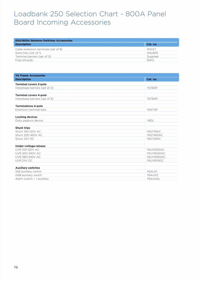
7/21/2019 TE Dorman Smith Product Portofolio 2011
http://slidepdf.com/reader/full/te-dorman-smith-product-portofolio-2011 78/182
76
630/800A Skeleton Switches Accessories
Description Cat. no.
Cable extension terminals (set of 8) SNCETSolid links (set of 1) HNL800
Terminal barriers (set of 3) Supplied
Fuse shrouds SNFS
Y6 Frame Accessories
Description Cat. no.
Terminal covers 3-pole
Interphase barriers (set of 2) Y5TB3P
Terminal covers 4-pole
Interphase barriers (set of 3) Y5TB4P
Terminations 4-pole
Extension terminal bars Y6XT4P
Locking devices
Dolly padlock device Y6DL
Shunt trips
Shunt 100-120V AC Y6ST115AC
Shunt 200-450V AC Y6ST450AC
Shunt 24V DC Y6ST24DC
Under-voltage releaseUVR 100-120V AC Y6UVR120AC
UVR 200-240V AC Y6UVR240AC
UVR 380-450V AC Y6UVR450AC
UVR 24V DC Y6UVR24DC
Auxiliary switches
1AB auxiliary switch Y6AUX1
2AB auxiliary switch Y6AUX2
Alarm switch + 1 auxiliary Y6AUXAL
Loadbank 250 Selection Chart - 800A PanelBoard Incoming Accessories
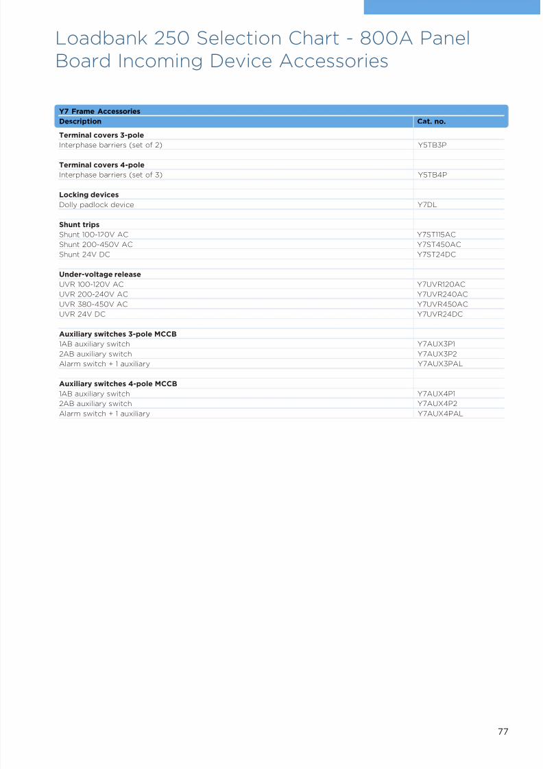
7/21/2019 TE Dorman Smith Product Portofolio 2011
http://slidepdf.com/reader/full/te-dorman-smith-product-portofolio-2011 79/182
77
Y7 Frame Accessories
Description Cat. no.
Terminal covers 3-poleInterphase barriers (set of 2) Y5TB3P
Terminal covers 4-pole
Interphase barriers (set of 3) Y5TB4P
Locking devices
Dolly padlock device Y7DL
Shunt trips
Shunt 100-120V AC Y7ST115AC
Shunt 200-450V AC Y7ST450AC
Shunt 24V DC Y7ST24DC
Under-voltage release
UVR 100-120V AC Y7UVR120AC
UVR 200-240V AC Y7UVR240AC
UVR 380-450V AC Y7UVR450AC
UVR 24V DC Y7UVR24DC
Auxiliary switches 3-pole MCCB
1AB auxiliary switch Y7AUX3P1
2AB auxiliary switch Y7AUX3P2
Alarm switch + 1 auxiliary Y7AUX3PAL
Auxiliary switches 4-pole MCCB
1AB auxiliary switch Y7AUX4P1
2AB auxiliary switch Y7AUX4P2Alarm switch + 1 auxiliary Y7AUX4PAL
Loadbank 250 Selection Chart - 800A PanelBoard Incoming Device Accessories

7/21/2019 TE Dorman Smith Product Portofolio 2011
http://slidepdf.com/reader/full/te-dorman-smith-product-portofolio-2011 80/182
78
Loadbank 250 Selection Chart - 800A PanelBoards Outgoing Devices
Outgoing Devices for Form 3 Panel Boards
Current rating (A) 1-pole cat. no. 3-pole cat. no.
Max. Min.YA3 frame MCCB - 25kA
16 - YA3N1P16T -
20 - YA3N1P20T YA3N3P20T
32 - YA3N1P32T YA3N3P32T
40 - YA3N1P40T -
50 - YA3N1P50T YA3N3P50T
63 - YA3N1P63T YA3N3P63T
80 - YA3N1P80T -
100 - YA3N1P100T YA3N3P100T
125 - YA3N1P125T YA3N3P125T
160 - YA3N1P160T YA3N3P160T
200 - - YA3N3P200T
250 - - YA3N3P250T
YA3 frame MCCB - 36kA
50 32 - YA3S3P50T
63 40 - YA3S3P63T
100 63 - YA3S3P100T
125 80 - YA3S3P125T
160 100 - YA3S3P160T
200 125 - YA3S3P200T
250 160 - YA3S3P250T
Outgoing Devices for Form 4 Panel Boards
Current rating (A) 4-pole 25kA 4-pole 36kA 4-pole 65kA
Max. Min. cat. no. cat. no. cat. no.
YA3 frame MCCB
20 13 YA3N4P20T - -
32 20 YA3N4P32T - -
50 32 YA3N4P50T YA3S4P50T YA3J4P50T
63 40 YA3N4P63T YA3S4P63T YA3J4P63T
100 63 YA3N4P100T YA3S4P100T YA3J4P100T
125 80 YA3N4P125T YA3S4P125T YA3J4P125T
160 100 YA3N4P160T YA3S4P160T YA3J4P160T
200 125 YA3N4P200T YA3S4P200T YA3J4P200T
250 160 YA3N4P250T YA3S4P250T YA3J4P250T
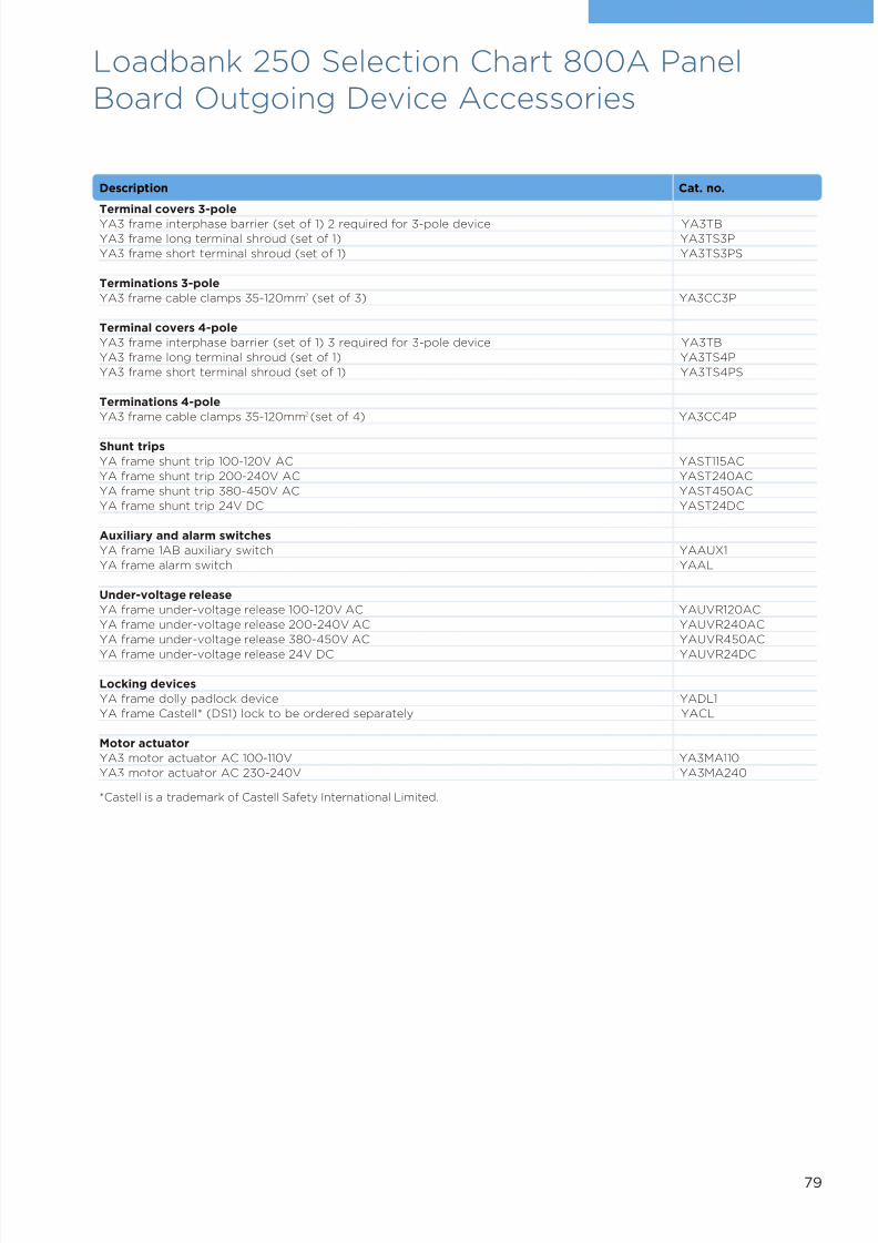
7/21/2019 TE Dorman Smith Product Portofolio 2011
http://slidepdf.com/reader/full/te-dorman-smith-product-portofolio-2011 81/182
79
Loadbank 250 Selection Chart 800A PanelBoard Outgoing Device Accessories
Description Cat. no.
Terminal covers 3-pole
YA3 frame interphase barrier (set of 1) 2 required for 3-pole device YA3TB
YA3 frame long terminal shroud (set of 1) YA3TS3P
YA3 frame short terminal shroud (set of 1) YA3TS3PS
Terminations 3-pole
YA3 frame cable clamps 35-120mm2 (set of 3) YA3CC3P
Terminal covers 4-pole
YA3 frame interphase barrier (set of 1) 3 required for 3-pole device YA3TB
YA3 frame long terminal shroud (set of 1) YA3TS4P
YA3 frame short terminal shroud (set of 1) YA3TS4PS
Terminations 4-pole
YA3 frame cable clamps 35-120mm2 (set of 4) YA3CC4P
Shunt trips
YA frame shunt trip 100-120V AC YAST115AC
YA frame shunt trip 200-240V AC YAST240AC
YA frame shunt trip 380-450V AC YAST450AC
YA frame shunt trip 24V DC YAST24DC
Auxiliary and alarm switches
YA frame 1AB auxiliary switch YAAUX1
YA frame alarm switch YAAL
Under-voltage release
YA frame under-voltage release 100-120V AC YAUVR120AC
YA frame under-voltage release 200-240V AC YAUVR240AC
YA frame under-voltage release 380-450V AC YAUVR450AC
YA frame under-voltage release 24V DC YAUVR24DC
Locking devices
YA frame dolly padlock device YADL1
YA frame Castell* (DS1) lock to be ordered separately YACL
Motor actuator
YA3 motor actuator AC 100-110V YA3MA110
YA3 motor actuator AC 230-240V YA3MA240
*Castell is a trademark of Castell Safety International Limited.
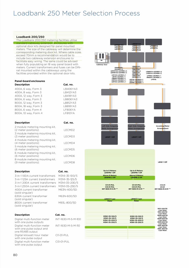
7/21/2019 TE Dorman Smith Product Portofolio 2011
http://slidepdf.com/reader/full/te-dorman-smith-product-portofolio-2011 82/182
Panel-board enclosures
Description Cat. no.
400A, 6 way, Form 3 LB406YA3
400A, 8 way, Form 3 LB412YA3400A, 12 way, Form 3 LB418YA3
800A, 6 way, Form 3 LB806YA3
800A, 12 way, Form 3 LB812YA3
800A, 18 way, Form 3 LB818YA3
800A, 6 way, Form 4 LF806YA
800A, 10 way, Form 4 LF810YA
Loadbank 200/250The Loadbank 200/250 metering facilities utilisestandard cableway extension enclosures with
optional door kits designed for panel mountedmeters. The size of the cableway will determine thecorresponding metering door kit. Where cable sizesexceed 70mm a recommendation would be toinclude two cableway extension enclosures tofacilitate easy wiring. The same could be advisedwhen fully populating an 18 way panel board withmeters. Current transformers and fuses can be DIN-rail mounted within the cableways using thefacilities provided within the optional door kits.
Description Cat. no.
2 module metering mounting kit,(2 meter positions) LECMD2
3 module metering mounting kit,(3 meter positions) LECMD3
4 module metering mounting kit,(4 meter positions) LECMD4
5 module metering mounting kit,(6 meter positions) LECMD5
6 module metering mounting kit,(6 meter positions) LECMD6
8 module metering mounting kit,(9 meter positions) LECMD8
Description Cat. no.
3-in-1 100A current transformers M3N1-35-100/5
3-in-1 125A current transformers M3N1-35-125/5
3-in-1 200A current transformers M3N1-35-200/5
3-in-1 250A current transformers M3N1-35-250/5400A current transformer M63N-400/5D(sold singular)
630A current transformer M63N-600/5D(sold singular)
800A current transformer M93L-800/5D(sold singular)
Description Cat. no.
Digital multi-function meter INT-1630-M-5-M-100with one pulse outputs
Digital multi-function meter INT-1630-M-5-M-110with one pulse output andone RS485 output
Digital kilowatt hour meter CI1-01-PULwith one pulse output
Digital multi-function meter CI3-01-PULwith one pulse output
80
Loadbank 250 Meter Selection Process
Cableway Door
LBWP 1 Off LBWP 1 Off
Left Side Outgoing
Meter Arrangement
Right Side Outgoing
Meter Arrangement
Incoming Meter
Arrangement
LBWI 1 Off
Up to 6 Meters:
LBWM6 1 Off
Above 6 Meters:
LBWM6 2 Off
Up to 6 Meters:
LBWM6 1 Off
Above 6 Meters:
LBWM6 2 Off
CI1-01-PUL
CI3-01-PULINT-1630-M-5-M-***
CI1-01-PUL
CI3-01-PULINT-1630-M-5-M-***
CI3-01
CI1-01INT-1630-M-5-M-***
LBWCT 1 perMeter
LBWCT 1 perMeter
M3N1-35-100/5M3N1-35-125/5
M3N1-35-200/5M3N1-35-250/5
M3N1-35-100/5M3N1-35-125/5
M3N1-35-200/5M3N1-35-250/5
M53J-200/5D3 per Meter
M53J-250/5D3 per Meter
M63N-400/5D3 per Meter
M63N-600/5D3 per Meter
M63N-800/5D3 per Meter
M93L-600/5D3 per Meter
M93L-800/5D3 per Meter
LB406YA3
LB412YA3LB418YA3
LB806YA3
LB812YA3LB818YA3
LB802YA5
LF806YALF810YA
LB406YA3:-LECMD4 x 2
LB412YA3:-LECMD6 x 2LB418YA3:-LECMD8 x 2
LB1YA3:-LECMD3 x 1LB1Y6:-LECMD5 x 1LBDR4:-LECMD2 x 1LB1F2A:-LECMD3 x 1LB1F4A:-LECMD5 x 1
LB806YA3:-LECMD4 x 2LB812YA3:-LECMD6 x 2LB818YA3:-LECMD8 x 2LB802YA5:-LECMD3 x 2
LB1Y6:-LECMD5 x 1LB1Y7:-LECMD6 x 1LBDR8:-LECMD3 x 1
LF806YA:-LECMD5 x 2LF810YA:-LECMD8 x 2
LF1F8A:-LECMD5 x 1MMS15Y:-LECMD6 x 1
LF1F4A
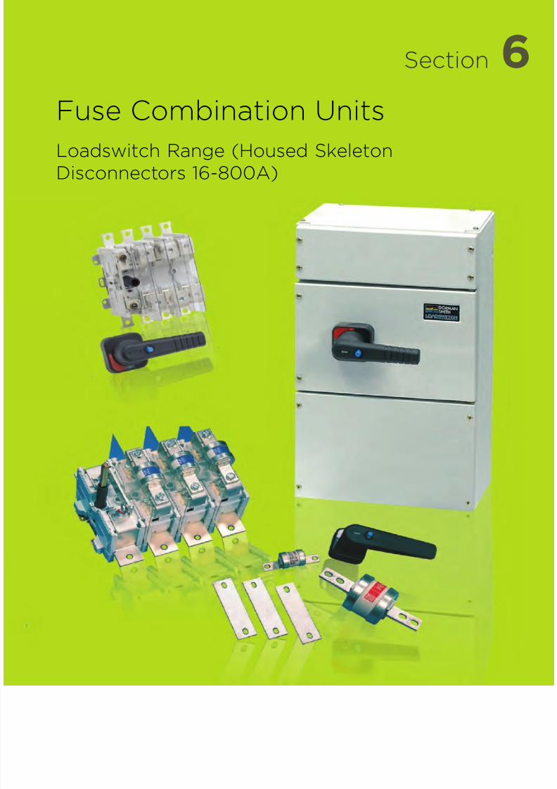
7/21/2019 TE Dorman Smith Product Portofolio 2011
http://slidepdf.com/reader/full/te-dorman-smith-product-portofolio-2011 83/182
6Section
Fuse Combination Units
Loadswitch Range (Housed SkeletonDisconnectors 16-800A)
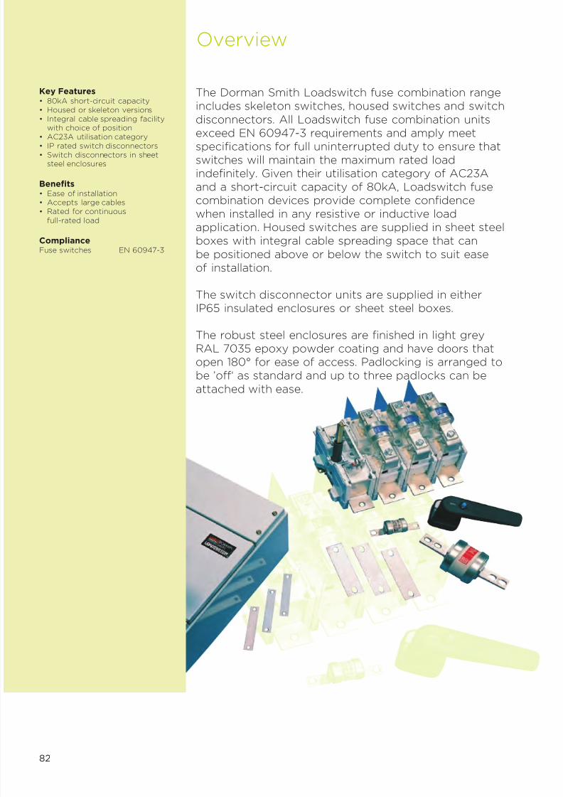
7/21/2019 TE Dorman Smith Product Portofolio 2011
http://slidepdf.com/reader/full/te-dorman-smith-product-portofolio-2011 84/182
82
Key Features• 80kA short-circuit capacity• Housed or skeleton versions• Integral cable spreading facility
with choice of position
• AC23A utilisation category• IP rated switch disconnectors• Switch disconnectors in sheet
steel enclosures
Benefits• Ease of installation• Accepts large cables• Rated for continuous
full-rated load
ComplianceFuse switches EN 60947-3
Overview
The Dorman Smith Loadswitch fuse combination rangeincludes skeleton switches, housed switches and switch
disconnectors. All Loadswitch fuse combination unitsexceed EN 60947-3 requirements and amply meetspecifications for full uninterrupted duty to ensure thatswitches will maintain the maximum rated loadindefinitely. Given their utilisation category of AC23Aand a short-circuit capacity of 80kA, Loadswitch fusecombination devices provide complete confidencewhen installed in any resistive or inductive loadapplication. Housed switches are supplied in sheet steelboxes with integral cable spreading space that can
be positioned above or below the switch to suit easeof installation.
The switch disconnector units are supplied in eitherIP65 insulated enclosures or sheet steel boxes.
The robust steel enclosures are finished in light greyRAL 7035 epoxy powder coating and have doors thatopen 180° for ease of access. Padlocking is arranged tobe ’off‘ as standard and up to three padlocks can be
attached with ease.

7/21/2019 TE Dorman Smith Product Portofolio 2011
http://slidepdf.com/reader/full/te-dorman-smith-product-portofolio-2011 85/182
83
Housed Switches
Skeleton Switches
32A
63/125A
160/200A
315/400A
630/800A
160/200A
63/125A
315/400A
630/800A

7/21/2019 TE Dorman Smith Product Portofolio 2011
http://slidepdf.com/reader/full/te-dorman-smith-product-portofolio-2011 86/182
Housed Switches – 32A Completewith Fuses• Exceeds the requirements of EN
60947-3• All terminals supplied with cable
clamps• Full withstand duty
• 80kA rms fused short-circuit capacity• 415V AC rated voltage• Supplied with fuse links, solid links are
an optional accessory• AC23A utilisation category
• IP4X Ingress Protection• Not supplied with fuse links• For fuse links see page 89
Housed Switches – 63/125AComplete with Fuses• Exceeds the requirements of EN
60947-3• All terminals supplied with lug-fixing
screws
• Full withstand duty
• 80kA rms fused short-circuit capacity• 415V AC rated voltage• Supplied with fuse links, solid links are
an optional accessory• AC23A utilisation category• IP4X Ingress Protection
• Not supplied with fuse links• For fuse links see page 89
Housed Switches – 160/200A• Exceeds the requirements of EN
60947-3• All terminals supplied with lug-fixing
screws• Full withstand duty
• 80kA rms fused short-circuit capacity• 415V AC rated voltage• AC23A utilisation category• IP4X Ingress Protection• Not supplied with fuse links• For fuse links see page 89
32 – HBE3P32N –
Current rating (A) 3-pole cat. no. 3-pole+N cat. no. 4-pole cat. no.
63 HBF3P63N -100 HBF3P100N HBF4P100125 HBF3P125N -
Current rating (A) 3-pole+N cat. no. 4-pole cat. no.
160 HBF3P160N -200 HBF3P200N HBF4P200
Current rating (A) 3-pole+N cat. no. 4-pole cat. no.
315 HBK3P315N -400 HBL3P400N HBL4P400
Current rating (A) 3-pole+N cat. no. 4-pole cat. no.
630 HBN3P630N -800 HBN3P800N HBN4P800
Current rating (A) 3-pole+N cat. no. 4-pole cat. no.
Housed Switches – 315/400A• Exceeds the requirements of EN
60947-3• All terminals supplied with lug-fixing
screws• Full withstand duty
• 80kA rms fused short-circuit capacity• 415V AC rated voltage• AC23A utilisation category• IP4X Ingress Protection• Not supplied with fuse links• For fuse links see page 89
Housed Switches – 630/800A• Exceeds the requirements of EN
60947-3• All terminals supplied with lug-fixing
screws• Full withstand duty
• 80kA rms fused short-circuit capacity• 415V AC rated voltage• AC23A utilisation category• IP4X Ingress Protection• Not supplied with fuse links• For fuse links see page 89
LoadswitchEnclosed Fuse Switch Combination Units 32A-800A
84
For solid isolator links see page 85.
For solid isolator links see page 85.
For solid isolator links see page 85.

7/21/2019 TE Dorman Smith Product Portofolio 2011
http://slidepdf.com/reader/full/te-dorman-smith-product-portofolio-2011 87/182
85
Accessories for Housed Switches
Cable spreader box 63/125 1 HB125CSB
160/200 1 HB200CSB315/400 1 HB400CSB630/800 1 HB800CSB
Solid links (set of 1) 32 2 HEL3263 2 HFL63
125-200 2 HFL200A315/400 2 HLL400630/800 2 HNL800
Castell* lock mounting kit All – SCLKCastell* lock with key (see note) All 3 FS22-bank auxiliary switch 63/200 4 SAUX2F
315/800 4 SAUX2N4-bank auxiliary switch 63/200 4 SAUX4F
315/800 4 SAUX4N6-bank auxiliary switch 315/800 4 SAUX6N
Description Current Picture Cat. no.rating (A)
Note: Standard symbol DS1, special symbols are available direct from Castell. Quotereference: Castell FS2 - Spigot 9.5mm square x 22.5mm, 65˚ anti-clockwise to trap key
*Castell is a trademark of Castell Safety International Limited.
1
2
4
3
Housed Switches Technical Data
Max. current rating (A) = 32 125 200
Rated current (A) 315 400 630 800Frame size K L N NMechanical endurance 8,000 5,000 5,000 3,000
Fused s/c current kA rms 80 80 80 80kW @ 415V AC 160 230 330 450Max. cable (mm2)* 185** 300 630 630Terminals M10 M10 4xM8 4xM8
M10 M10 1xM16 1xM16
Max cable lug palm width 35 50 80 80Weight (kg) 21 21 37 37
Max. current rating (A) = 400 800
* These figures are for guidance only and are dependent upon lug palm width.** 240mm2 with terminal barriers
Housed Switches Dimensions
32 210 210 220 363 420 263 273 6100 420 263 273 6125 420 263 273 6
160 525 315 325 12200 525 315 325 12315 735 420 325 21400 735 420 325 21630 840 630 378 37800 840 630 378 37
Current Height Width Depth over Weightrating (A) (mm) (mm) handle (mm) (kg)
Spreader Box Dimensions
63A-125A 105 263 183 HB125CSB200A 105 315 235 HB200CSB315-400A 210 420 235 HB400CSB630-800A 210 630 288 HB800CSB
Current Height Width Depth over Weightrating (A) (mm) (mm) handle (mm) (kg)
All dimensions in mm
Rated current (A) 32 63 100 125 160 200Frame size E F FMechanical endurance 10,000 10,000 10,000 8,000 8,000 8,000
Fused s/c current kA rms 80 80 80 80 80 80kW @ 415V AC 15 30 55 75 90 110Max. cable (mm2)* 10 70 70 70 150 150Terminals Clamp type M8 M8 M8 M8 M8Max cable lug palm width – 22 22 22 22 22
Weight (kg) 3 6 6 6 12 12
32A Top and Bottom KnockOut Dimensions
63 - 125A Top and BottomKnock Out Dimensions
630-800A Loadswitch Terminal
LoadswitchEnclosed Fuse Switch Combination Units Accessories

7/21/2019 TE Dorman Smith Product Portofolio 2011
http://slidepdf.com/reader/full/te-dorman-smith-product-portofolio-2011 88/182
86
Current rating (A) 3-pole+N cat. no. 4-pole cat. no.
63 SF3P63N SF4P63
100 SF3P100N SF4P100
125 SF3P125N SF4P125
Current rating (A) 3-pole+N cat. no. 4-pole cat. no.
160 SF3P160N SF4P160
200 SF3P200N SF4P200
Current rating (A) 3-pole+N cat. no. 4-pole cat. no.
315 SK3P315N SK4P315
400 SL3P400N SL4P400
Current rating (A) 3-pole+N cat. no. 4-pole cat. no.
630 SN3P630N SN4P630
800 SN3P800N SN4P800
Skeleton Switches – 63/125A• Exceeds the requirements of EN 60947-3• 80kA rms fused short-circuit capacity• AC23A utilisation category• Full uninterrupted duty
• 415V AC rated voltage• Lug fixings not supplied
Skeleton Switches – 160/200A• Exceeds the requirements of EN 60947-3
• 80kA rms fused short-circuit capacity• AC23A utilisation category• Full uninterrupted duty• 415V AC rated voltage• Lug fixings not supplied
Skeleton Switches – 315/400A• Exceeds the requirements of EN 60947-3• 80kA rms fused short-circuit capacity• AC23A utilisation category• Full uninterrupted duty• 415V AC rated voltage• Lug fixings not supplied
Skeleton Switches – 630/800A• Exceeds the requirements of EN 60947-3• 80kA rms fused short-circuit capacity• AC23A utilisation category• Full uninterrupted duty• 415V AC rated voltage• Lug fixings not supplied
LoadswitchSkeleton Switches (Without Fuses)
For fuse links see page 89.

7/21/2019 TE Dorman Smith Product Portofolio 2011
http://slidepdf.com/reader/full/te-dorman-smith-product-portofolio-2011 89/182
87
2
1
3 4
5
6
Accessories for Skeleton Switches
Description Current Picture Cat. no.
rating (A)
Cable extension terminals (set of 8) 630/800 – SNCETSolid links (set of 1) 63 1 HFL63
100/200 1 HFL200A
315/400 1 HLL400
630/800 1 HNL800
2-bank auxiliary switch 63/200 3 SAUX2F
315/800 3 SAUX2N
4-bank auxiliary switch 63/200 3 SAUX4F
315/800 3 SAUX4N
6-bank auxiliary switch 315/800 3 SAUX6N
Castell* lock mounting kit
(standard symbol DS1 – see note) All – SCLK
Castell* lock with key 32/800 2 FS2
Handle assembly for:
E frame - standard size – 5 SHA1F frame - standard size – 5 SHA2
K + L frame - special reduced size – 5 SHA3
KL+N frame - standard size – 5 SHA4
Shaft extensions 63A - 200A 4 SXT127for panel depth 270mm 315A - 800A 4 SXT227
Shaft extensions 63A - 200A 4 SXT160for panel depth 600mm 315A - 800A 4 SXT260
Terminal shrouds 160/200 – SFTSL(recommended for cable sizes above 70mm)
63/200 – SFTSS
315 – SKTS
400 – SLTS630/800 – SNTS
Terminal barriers (set of 3) 63/200 – SFTB
315 – SKTB
400 – SLTB
630/800 – Supplied
Fuse shrouds (set of 3) 63/125 – SFFS125
160/200 – SFFS200
315 – SKFS
400 – SLFS
630/800 – SNFS
Rating label (strip of 8) 63 6 SRLB63
100 6 SRLB100
125 6 SRLB125
160 6 SRLB160
200 6 SRLB200
315 6 SRLB315
400 6 SRLB400
630 6 SRLB630
800 6 SRLB800
Note: Special symbols are available direct from Castell.Quote reference: Castell FS2 - Spigot 9.5mm square x 22.5mm, 65˚ anti clockwiseto trap key.
*Castell is a trademark of Castell Safety International Ltd.
LoadswitchSkeleton Switch Accessories
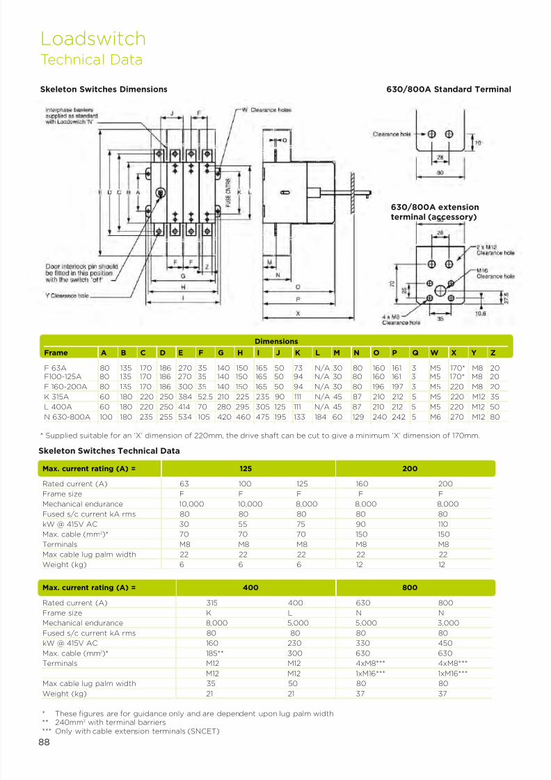
7/21/2019 TE Dorman Smith Product Portofolio 2011
http://slidepdf.com/reader/full/te-dorman-smith-product-portofolio-2011 90/182
88
* These figures are for guidance only and are dependent upon lug palm width** 240mm2 with terminal barriers*** Only with cable extension terminals (SNCET)
Dimensions
Frame A B C D E F G H I J K L M N O P Q W X Y Z
F 63A 80 135 170 186 270 35 140 150 165 50 73 N/A 30 80 160 161 3 M5 170* M8 20F100-125A 80 135 170 186 270 35 140 150 165 50 94 N/A 30 80 160 161 3 M5 170* M8 20
F 160-200A 80 135 170 186 300 35 140 150 165 50 94 N/A 30 80 196 197 3 M5 220 M8 20
K 315A 60 180 220 250 384 52.5 210 225 235 90 111 N/A 45 87 210 212 5 M5 220 M12 35
L 400A 60 180 220 250 414 70 280 295 305 125 111 N/A 45 87 210 212 5 M5 220 M12 50N 630-800A 100 180 235 255 534 105 420 460 475 195 133 184 60 129 240 242 5 M6 270 M12 80
Skeleton Switches Dimensions 630/800A Standard Terminal
* Supplied suitable for an ‘X’ dimension of 220mm, the drive shaft can be cut to give a minimum ‘X’ dimension of 170mm.
630/800A extensionterminal (accessory)
Max. current rating (A) = 400 800
Rated current (A) 315 400 630 800
Frame size K L N N
Mechanical endurance 8,000 5,000 5,000 3,000
Fused s/c current kA rms 80 80 80 80
kW @ 415V AC 160 230 330 450
Max. cable (mm2)* 185** 300 630 630
Terminals M12 M12 4xM8*** 4xM8***
M12 M12 1xM16*** 1xM16***
Max cable lug palm width 35 50 80 80
Weight (kg) 21 21 37 37
LoadswitchTechnical Data
Skeleton Switches Technical Data
Max. current rating (A) = 125 200
Rated current (A) 63 100 125 160 200
Frame size F F F F F
Mechanical endurance 10,000 10,000 8,000 8,000 8,000
Fused s/c current kA rms 80 80 80 80 80
kW @ 415V AC 30 55 75 90 110
Max. cable (mm2)* 70 70 70 150 150
Terminals M8 M8 M8 M8 M8Max cable lug palm width 22 22 22 22 22
Weight (kg) 6 6 6 12 12
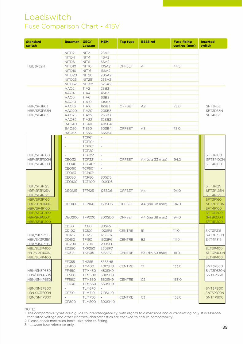
7/21/2019 TE Dorman Smith Product Portofolio 2011
http://slidepdf.com/reader/full/te-dorman-smith-product-portofolio-2011 91/182
89
NOTE:1. The comparative types are a guide to interchangeability, with regard to dimensions and current rating only. It is essential
that rated voltage and other electrical characteristics are checked to ensure compatability.2. Please check maximum barrel size prior to fitting.3. *Lawson fuse reference only.
LoadswitchFuse Comparison Chart - 415V
Standard Bussman GEC/ MEM Tag type BS88 ref Fuse fixing Insertedswitch Lawson centres (mm) switch
NITD2 NIT2 2SA2
NITD4 NIT4 4SA2
NITD6 NIT6 6SA2
HBE3P32N NITD10 NIT10 10SA2 OFFSET A1 44.5
NITD16 NIT16 16SA2
NITD20 NIT20 20SA2
NITD25 NIT25* 25SA2
NITD32 NIT32* 32SA2
AAO2 TIA2 2SB3
AAO4 TIA4 4SB3
AAO6 TIA6 6SB3
AAO10 TIA10 10SB3
HBF/SF3P63 AAO16 TIA16 16SB3 OFFSET A2 73.0 SFT3P63
HBF/SF3P63N AAO20 TIA20 20SB3 SFT3P63N
HBF/SF4P63 AAO25 TIA25 25SB3 SFT4P63
AAO32 TIA32 32SB3BAO40 TIS40 40SB4
BAO50 TIS50 50SB4 OFFSET A3 73.0
BAO63 TIS63 63SB4
– TCP6* –
– TCP10* –
– TCP16* –
– TCP20* –
HBF/SF3P100 – TCP25* – SFT3P100
HBF/SF3P100N CEO32 TCP32* – OFFSET A4 (dia 33 max) 94.0 SFT3P100N
HBF/SF4P100 CEO40 TCP40* – SFT4P100
CEO50 TCP50* –
CEO63 TCP63* –
CE080 TCP80 80SD5
CEO100 TCP100 100SD5
HBF/SF3P125 SFT3P125
HBF/SF3P125N DEO125 TFP125 125SD6 OFFSET A4 94.0 SFT3P125N
HBF/SF4P125 SFT4P125
HBF/SF3P160 SFT3P160
HBF/SF3P160N DEO160 TFP160 160SD6 OFFSET A4 (dia 38 max) 94.0 SFT3P160N
HBF/SF4P160 SFT4P160
HBF/SF3P200 SFT3P200
HBF/SF3P200N DEO200 TFP200 200SD6 OFFSET A4 (dia 38 max) 94.0 SFT3P200N
HBF/SF4P200 SFT4P200
CD80 TC80 80SF5
CD100 TC100 100SF5 CENTRE B1 111.0 SKT3P315
HBK/SK3P315 DD125 TF125 125SF6 SKT3P315N
HBK/SK3P315N DD160 TF160 160SF6 CENTRE B2 111.0 SKT4P315HBK/SK4P315 DD200 TF200 200SF6
HBL/SL3P400 ED250 TKF250 250SF7 SLT3P400
HBL/SL3P400N ED315 TKF315 315SF7 CENTRE B3 (dia 50 max) 111.0 SLT3P400N
HBL/SL4P400 SLT4P400
EF355 TM355 355SH8
EF400 TM400 400SH8 CENTRE C1 133.0 SNT3P630
HBN/SN3P630 FF450 TTM450 450SH9 SNT3P630N
HBN/SN3P630N FF500 TTM500 500SH9 SNT4P630
HBN/SN4P630 FF560 TTM560 560SH9 CENTRE C2 133.0
FF630 TTM630 630SH9
HBN/SN3P800 – TLM670 – SNT3P800
HBN/SN3P800N GF710 TLM710 710SH10 SNT3P800N
HBN/SN4P800 – TLM750 – CENTRE C3 133.0 SNT4P800
GF800 TLM800 800SH10
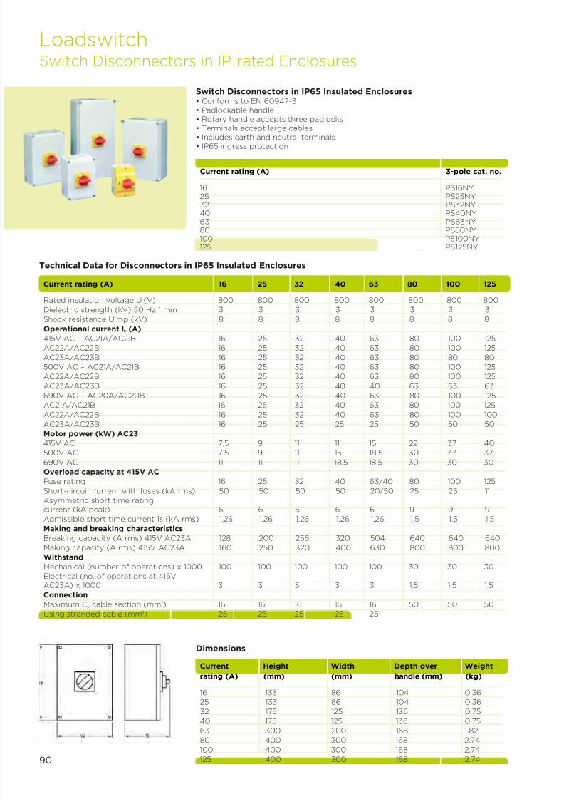
7/21/2019 TE Dorman Smith Product Portofolio 2011
http://slidepdf.com/reader/full/te-dorman-smith-product-portofolio-2011 92/182
Current rating (A) 3-pole cat. no.
16 PS16NY25 PS25NY32 PS32NY40 PS40NY63 PS63NY80 PS80NY100 PS100NY125 PS125NY
Dimensions
Current Height Width Depth over Weight
rating (A) (mm) (mm) handle (mm) (kg)
16 133 86 104 0.36
25 133 86 104 0.36
32 175 125 136 0.75
40 175 125 136 0.75
63 300 200 168 1.82
80 400 300 168 2.74
100 400 300 168 2.74
125 400 300 168 2.74
Switch Disconnectors in IP65 Insulated Enclosures• Conforms to EN 60947-3• Padlockable handle• Rotary handle accepts three padlocks• Terminals accept large cables
• Includes earth and neutral terminals• IP65 ingress protection
Current rating (A) 16 25 32 40 63 80 100 125
Rated insulation voltage Ui (V) 800 800 800 800 800 800 800 800
Dielectric strength (kV) 50 Hz 1 min 3 3 3 3 3 3 3 3
Shock resistance Uimp (kV) 8 8 8 8 8 8 8 8
Operational current Ie (A)
415V AC – AC21A/AC21B 16 25 32 40 63 80 100 125
AC22A/AC22B 16 25 32 40 63 80 100 125
AC23A/AC23B 16 25 32 40 63 80 80 80
500V AC – AC21A/AC21B 16 25 32 40 63 80 100 125
AC22A/AC22B 16 25 32 40 63 80 100 125
AC23A/AC23B 16 25 32 40 40 63 63 63
690V AC – AC20A/AC20B 16 25 32 40 63 80 100 125
AC21A/AC21B 16 25 32 40 63 80 100 125
AC22A/AC22B 16 25 32 40 63 80 100 100AC23A/AC23B 16 25 25 25 25 50 50 50
Motor power (kW) AC23
415V AC 7.5 9 11 11 15 22 37 40
500V AC 7.5 9 11 15 18.5 30 37 37
690V AC 11 11 11 18.5 18.5 30 30 30
Overload capacity at 415V AC
Fuse rating 16 25 32 40 63/40 80 100 125
Short-circuit current with fuses (kA rms) 50 50 50 50 20/50 25 25 11
Asymmetric short time ratingcurrent (kA peak) 6 6 6 6 6 9 9 9
Admissible short time current 1s (kA rms) 1.26 1.26 1.26 1.26 1.26 1.5 1.5 1.5
Making and breaking characteristics
Breaking capacity (A rms) 415V AC23A 128 200 256 320 504 640 640 640
Making capacity (A rms) 415V AC23A 160 250 320 400 630 800 800 800
WithstandMechanical (number of operations) x 1000 100 100 100 100 100 30 30 30
Electrical (no. of operations at 415VAC23A) x 1000 3 3 3 3 3 1.5 1.5 1.5
Connection
Maximum Cu cable section (mm2) 16 16 16 16 16 50 50 50
Using stranded cable (mm2) 25 25 25 25 25 – – –
Technical Data for Disconnectors in IP65 Insulated Enclosures
LoadswitchSwitch Disconnectors in IP rated Enclosures
90
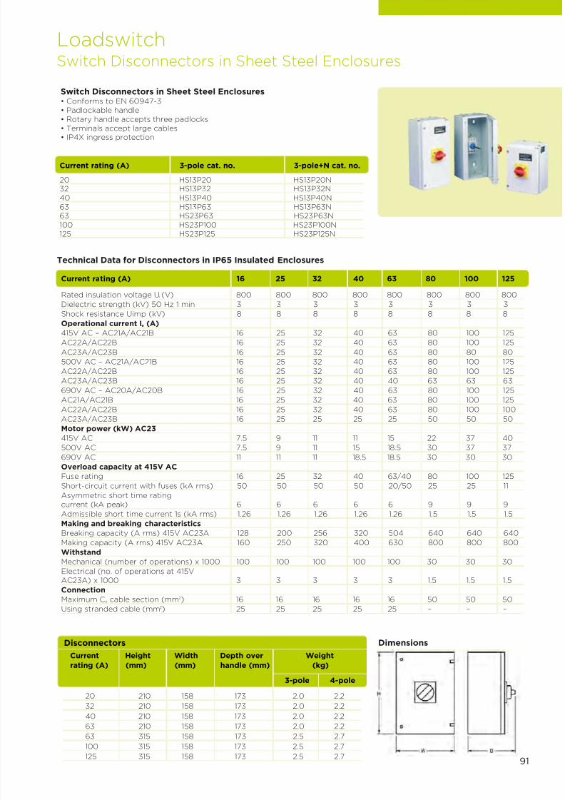
7/21/2019 TE Dorman Smith Product Portofolio 2011
http://slidepdf.com/reader/full/te-dorman-smith-product-portofolio-2011 93/182
91
Current rating (A) 16 25 32 40 63 80 100 125
Rated insulation voltage Ui (V) 800 800 800 800 800 800 800 800
Dielectric strength (kV) 50 Hz 1 min 3 3 3 3 3 3 3 3
Shock resistance Uimp (kV) 8 8 8 8 8 8 8 8
Operational current Ie (A)
415V AC – AC21A/AC21B 16 25 32 40 63 80 100 125
AC22A/AC22B 16 25 32 40 63 80 100 125
AC23A/AC23B 16 25 32 40 63 80 80 80
500V AC – AC21A/AC21B 16 25 32 40 63 80 100 125
AC22A/AC22B 16 25 32 40 63 80 100 125
AC23A/AC23B 16 25 32 40 40 63 63 63
690V AC – AC20A/AC20B 16 25 32 40 63 80 100 125
AC21A/AC21B 16 25 32 40 63 80 100 125
AC22A/AC22B 16 25 32 40 63 80 100 100
AC23A/AC23B 16 25 25 25 25 50 50 50Motor power (kW) AC23
415V AC 7.5 9 11 11 15 22 37 40
500V AC 7.5 9 11 15 18.5 30 37 37
690V AC 11 11 11 18.5 18.5 30 30 30
Overload capacity at 415V AC
Fuse rating 16 25 32 40 63/40 80 100 125
Short-circuit current with fuses (kA rms) 50 50 50 50 20/50 25 25 11
Asymmetric short time ratingcurrent (kA peak) 6 6 6 6 6 9 9 9
Admissible short time current 1s (kA rms) 1.26 1.26 1.26 1.26 1.26 1.5 1.5 1.5
Making and breaking characteristics
Breaking capacity (A rms) 415V AC23A 128 200 256 320 504 640 640 640
Making capacity (A rms) 415V AC23A 160 250 320 400 630 800 800 800
Withstand
Mechanical (number of operations) x 1000 100 100 100 100 100 30 30 30
Electrical (no. of operations at 415VAC23A) x 1000 3 3 3 3 3 1.5 1.5 1.5
Connection
Maximum Cu cable section (mm2) 16 16 16 16 16 50 50 50
Using stranded cable (mm2) 25 25 25 25 25 – – –
Technical Data for Disconnectors in IP65 Insulated Enclosures
Switch Disconnectors in Sheet Steel Enclosures• Conforms to EN 60947-3• Padlockable handle• Rotary handle accepts three padlocks• Terminals accept large cables
• IP4X ingress protection
Current rating (A) 3-pole cat. no. 3-pole+N cat. no.
20 HS13P20 HS13P20N32 HS13P32 HS13P32N40 HS13P40 HS13P40N63 HS13P63 HS13P63N63 HS23P63 HS23P63N100 HS23P100 HS23P100N125 HS23P125 HS23P125N
LoadswitchSwitch Disconnectors in Sheet Steel Enclosures
Current Height Width Depth over Weight
rating (A) (mm) (mm) handle (mm) (kg)
3-pole 4-pole
20 210 158 173 2.0 2.232 210 158 173 2.0 2.2
40 210 158 173 2.0 2.2
63 210 158 173 2.0 2.2
63 315 158 173 2.5 2.7
100 315 158 173 2.5 2.7
125 315 158 173 2.5 2.7
DimensionsDisconnectors

7/21/2019 TE Dorman Smith Product Portofolio 2011
http://slidepdf.com/reader/full/te-dorman-smith-product-portofolio-2011 94/182
92
Accessories for Switch Disconnectors
Description Current rating (A) Cat. no.
63A neutral link All HSNL63125A neutral link All HSNL12510A auxiliary switch All HSAUXTerminal shroud (set of 2):1-pole 16/63 HSTS1633-pole 16/63 HSTS3631-pole 63/125 HSTS11253-pole 63/125 HSTS3125
LoadswitchSwitch Disconnectors Accessories

7/21/2019 TE Dorman Smith Product Portofolio 2011
http://slidepdf.com/reader/full/te-dorman-smith-product-portofolio-2011 95/182
7Section
Dorman Smith Circuit Protection
and Modular Devices
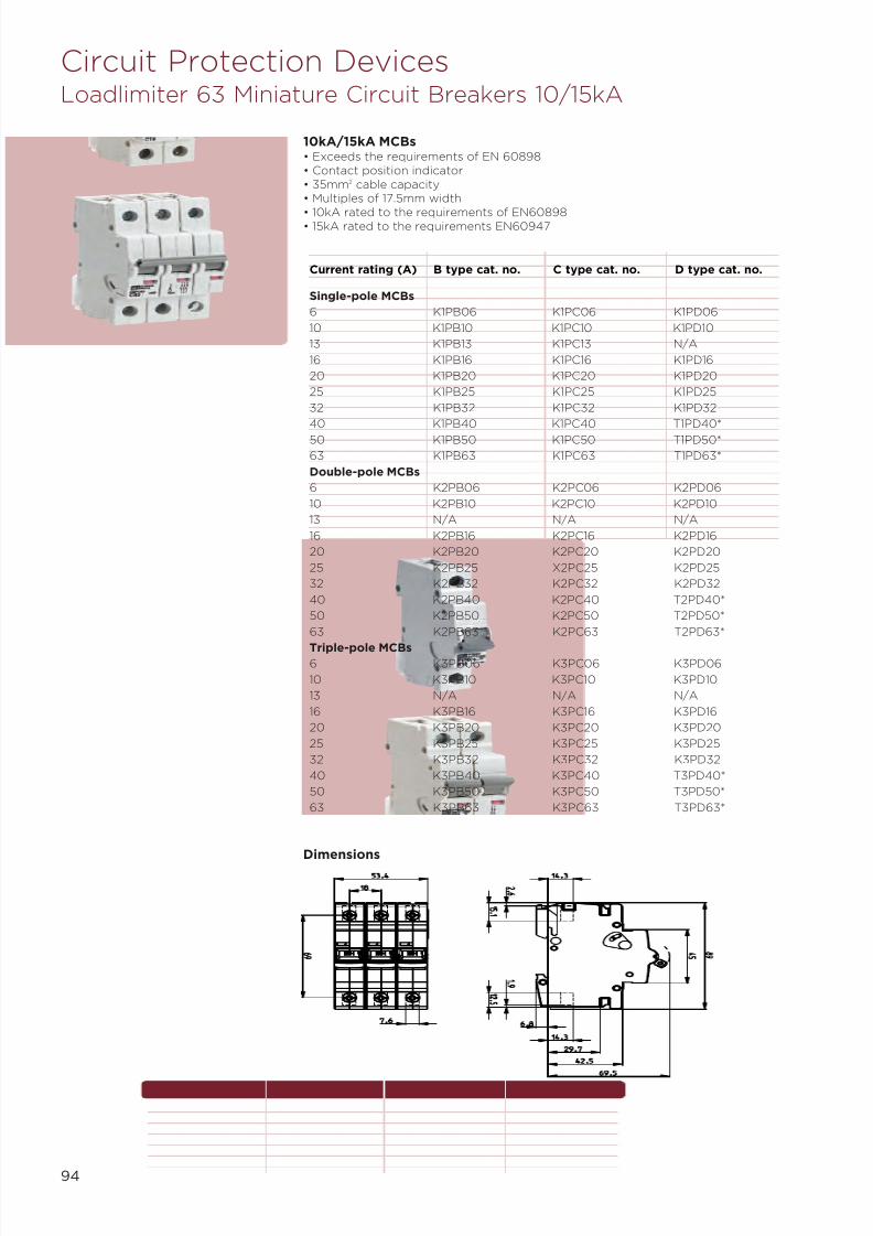
7/21/2019 TE Dorman Smith Product Portofolio 2011
http://slidepdf.com/reader/full/te-dorman-smith-product-portofolio-2011 96/182
94
Circuit Protection DevicesLoadlimiter 63 Miniature Circuit Breakers 10/15kA
10kA/15kA MCBs• Exceeds the requirements of EN 60898• Contact position indicator• 35mm2 cable capacity• Multiples of 17.5mm width
• 10kA rated to the requirements of EN60898• 15kA rated to the requirements EN60947
Current rating (A) B type cat. no. C type cat. no. D type cat. no.
Single-pole MCBs
6 K1PB06 K1PC06 K1PD06
10 K1PB10 K1PC10 K1PD10
13 K1PB13 K1PC13 N/A
16 K1PB16 K1PC16 K1PD16
20 K1PB20 K1PC20 K1PD20
25 K1PB25 K1PC25 K1PD25
32 K1PB32 K1PC32 K1PD32
40 K1PB40 K1PC40 T1PD40*
50 K1PB50 K1PC50 T1PD50*
63 K1PB63 K1PC63 T1PD63*
Double-pole MCBs
6 K2PB06 K2PC06 K2PD06
10 K2PB10 K2PC10 K2PD10
13 N/A N/A N/A
16 K2PB16 K2PC16 K2PD16
20 K2PB20 K2PC20 K2PD20
25 K2PB25 X2PC25 K2PD25
32 K2PB32 K2PC32 K2PD32
40 K2PB40 K2PC40 T2PD40*
50 K2PB50 K2PC50 T2PD50*
63 K2PB63 K2PC63 T2PD63*
Triple-pole MCBs6 K3PB06 K3PC06 K3PD06
10 K3PB10 K3PC10 K3PD10
13 N/A N/A N/A
16 K3PB16 K3PC16 K3PD16
20 K3PB20 K3PC20 K3PD20
25 K3PB25 K3PC25 K3PD25
32 K3PB32 K3PC32 K3PD32
40 K3PB40 K3PC40 T3PD40*
50 K3PB50 K3PC50 T3PD50*
63 K3PB63 K3PC63 T3PD63*
Dimensions

7/21/2019 TE Dorman Smith Product Portofolio 2011
http://slidepdf.com/reader/full/te-dorman-smith-product-portofolio-2011 97/182
Circuit Protection DevicesLoadlimiter 63 Residual Current Circuit Breaker with Overload
Current rating (A) Sensitivity B type cat. no. C type cat. no.
6 30 KR1PB0630 KR1PC063010 30 KR1PB1030 KR1PC103016 30 KR1PB1630 KR1PC163020 30 KR1PB2030 KR1PC203032 30 KR1PB3230 KR1PC323040 30 KR1PB4030 KR1PC403045 30 KR1PB4530 KR1PC45306 100 - KR1PC0610010 100 - KR1PC1010016 100 - KR1PC1610020 100 - KR1PC2010032 100 - KR1PC3210040 100 - KR1PC40100
10kA RCBOs• Exceeds the requirements of EN 61009• Single module: Type AC• 10kA rated breaking capacity• Terminal capacity: outgoing terminals 10mm2
• Terminal capacity: busbar side terminals 35mm2
Double Module RCBOs• Exceeds the requirements of
EN 61009, IEC 61009• SP&SwN configuration• Rated breaking capacity up to 10kA• Contact position indicator• Rated voltage Ue ~230V• Rated frequency 50Hz
• Energy limiting class 3• Type AC• Terminal capacity: outgoing
terminals 35mm2
• Terminal capacity: busbar sideterminals 35mm2
Current rating (A) 30m/A cat. no.
6 KR2PB063010 KR2PB103016 KR2PB163020 KR2PB203032 KR2PB323040 KR2PB4030
MCB shunt trip (240V AC) KST240
MCB auxiliary/switch contact KAUX1
Padlocking
MCB dolly locking device KDL
Padlock for dolly locking device XPL
Auxiliary equipment Cat. no.
Accessories for 10kA MCBs and RCBOs
95
126.4
45
34.5
98.2
109
4 . 3
6 .
8 6 .
6
4 3 . 1
6 9 . 5
1 7 .
4
Dimensions
Single Module Double Module

7/21/2019 TE Dorman Smith Product Portofolio 2011
http://slidepdf.com/reader/full/te-dorman-smith-product-portofolio-2011 98/182
96
Circuit Protection DevicesLoadlimiter 63 Miniature Circuit Breakers 6kA/10kA
6kA/10kA – MCBs• Exceeds the requirements of EN 60898• 6kA rated breaking capacity to EN 60898• Contact position indicator• 25mm2 cable capacity
• 10kA rated breaking capacity to EN 60947-2
Current rating (A) B type cat. no. C type cat. no. D type cat. no.
Single-pole MCBs6 S1PB06 S1PC06 S1PD0610 S1PB10 S1PC10 S1PD1016 S1PB16 S1PC16 S1PD1620 S1PB20 S1PC20 S1PD2025 S1PB25 S1PC25 S1PD2532 S1PB32 S1PC32 S1PD3240 S1PB40 S1PC40 S1PD4050 S1PB50 S1PC50 S1PD5063 S1PB63 S1PC63 S1PD63Double-pole MCBs
6 S2PB06 S2PC06 S2PD0610 S2PB10 S2PC10 S2PD1016 S2PB16 S2PC16 S2PD1620 S2PB20 S2PC20 S2PD2025 S2PB25 S2PC25 S2PD2532 S2PB32 S2PC32 S2PD3240 S2PB40 S2PC40 S2PD4050 S2PB50 S2PC50 S2PD5063 S2PB63 S2PC63 S2PD63Triple-pole MCBs6 S3PB06 S3PC06 S3PD0610 S3PB10 S3PC10 S3PD1016 S3PB16 S3PC16 S3PD1620 S3PB20 S3PC20 S3PD2025 S3PB25 S3PC25 S3PD25
32 S3PB32 S3PC32 S3PD3240 S3PB40 S3PC40 S3PD4050 S3PB50 S3PC50 S3PD5063 S3PB63 S3PC63 S3PD63
Dimensions
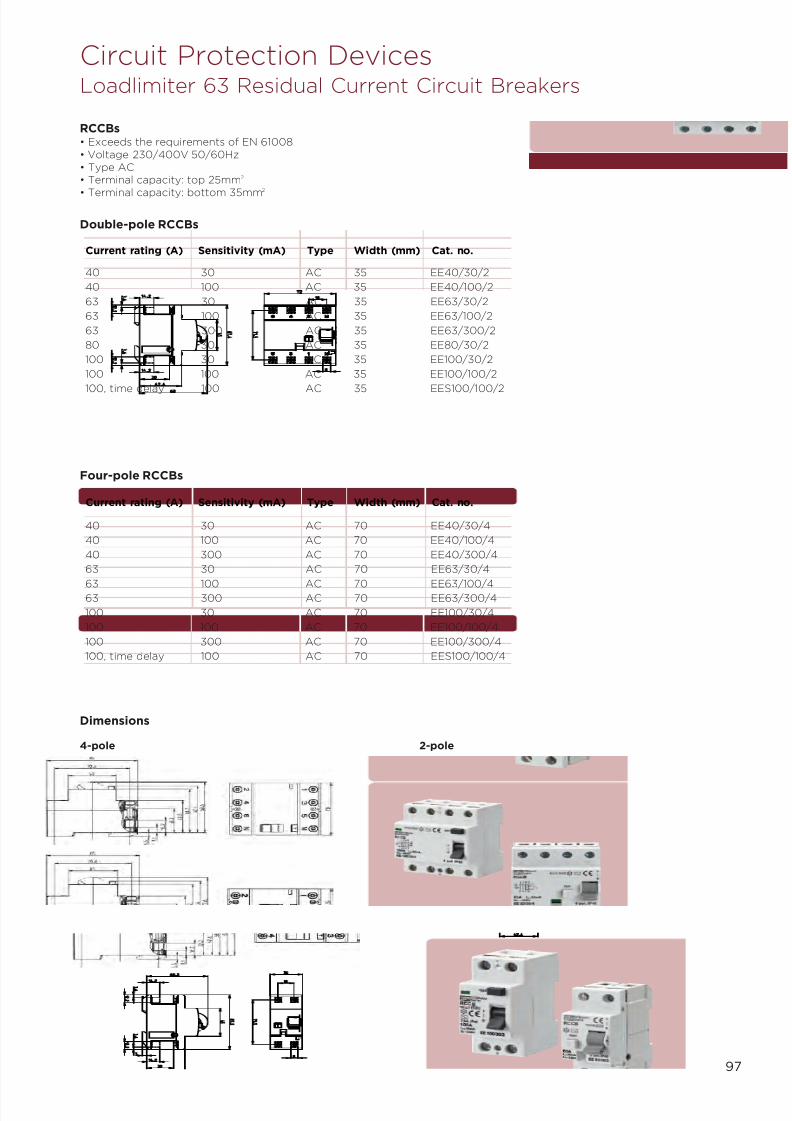
7/21/2019 TE Dorman Smith Product Portofolio 2011
http://slidepdf.com/reader/full/te-dorman-smith-product-portofolio-2011 99/182
97
Circuit Protection DevicesLoadlimiter 63 Residual Current Circuit Breakers
RCCBs• Exceeds the requirements of EN 61008• Voltage 230/400V 50/60Hz• Type AC• Terminal capacity: top 25mm2
• Terminal capacity: bottom 35mm2
Four-pole RCCBs
40 30 AC 35 EE40/30/2
40 100 AC 35 EE40/100/2
63 30 AC 35 EE63/30/2
63 100 AC 35 EE63/100/2
63 300 AC 35 EE63/300/2
80 30 AC 35 EE80/30/2
100 30 AC 35 EE100/30/2
100 100 AC 35 EE100/100/2
100, time delay 100 AC 35 EES100/100/2
Current rating (A) Sensitivity (mA) Type Width (mm) Cat. no.
40 30 AC 70 EE40/30/4
40 100 AC 70 EE40/100/4
40 300 AC 70 EE40/300/4
63 30 AC 70 EE63/30/4
63 100 AC 70 EE63/100/463 300 AC 70 EE63/300/4
100 30 AC 70 EE100/30/4
100 100 AC 70 EE100/100/4
100 300 AC 70 EE100/300/4
100, time delay 100 AC 70 EES100/100/4
Current rating (A) Sensitivity (mA) Type Width (mm) Cat. no.
Double-pole RCCBs
Dimensions
4-pole 2-pole

7/21/2019 TE Dorman Smith Product Portofolio 2011
http://slidepdf.com/reader/full/te-dorman-smith-product-portofolio-2011 100/182

7/21/2019 TE Dorman Smith Product Portofolio 2011
http://slidepdf.com/reader/full/te-dorman-smith-product-portofolio-2011 101/182
99
Circuit Protection DevicesLoadline Moulded Case Circuit Breakers
Frame YA3N YA3S YA3J YA5N YA5H
Maximum amps 250 250 250 400 400
No. of poles 1 3 4 3 4 3 4 3 4 3 4
Adjustable thermal N Y Y Y Y Y
Adjustable magnetics N N Y Y Y N
Rated current Nom Adj Adj Adj Adj Adj Adj Adj Adj Adj(A). [In] min max min max min max min max min max
16 16 – – – – – – – – – –
20 20 13 20 13 20 – – – – – –
25 25 – – – – – – – – – –
32 32 20 32 20 32 20 32 – – – –
40 40 – – – – – – – – – –
50 50 32 50 32 50 32 50 – – – –
63 63 40 63 40 63 40 63 – – – –
80 80 – – – – – – – – – –
100 100 63 100 63 100 63 100 – – – –
125 125 80 125 80 125 80 125 – – – –
160 160 100 160 100 160 100 160 – – – –
200 – 125 200 125 200 125 200 – – – –
250 – 160 250 160 250 160 250 160 250 160 250
400 – – – – – – – 250 400 250 400
Rated impulse withstand 8 8 8 8 8
voltage Uimp[kV]
AC rated insulation 800 800 800 800 800
voltage [Ui]
AC rated breaking capacity Icu Icu Ics Icu Ics Icu Ics Icu Ics Icu Ics
IEC 947-2 690V – – – 7.5 7.5 7.5 7.5 – – 20 15
EN 60947-2 525V – 10 7.5 25 25 25 25 15 15 30 30
CEI EN 60947-2 440V – 15 12 25 25 25 25 22 22 45 45
415V – 25 19 36*** 36*** 65 65 25 25 50 50
400V – 25 19 36*** 36*** 65 65 25 25 50 50
380V – 25 19 36*** 36*** 65 65 25 25 50 50
240V 25 35 27 65 65 85 85 35 35 35 85
220V 25 35 27 65 65 85 85 35 35 35 85
NEMA AB-1 600V – – – – – – – – – – –
480V – 10 – 22 – 22 – 15 – 22 –
240V – 35 – 65 – 85 – 35 – 50 –
Without
instantaneous
240-690V – – – – – – – – – – –DC rated 250V 19 25 25 40 40 40 40 25 25 40 40
breaking 125V
capacity
[kA]
Rated short time – – – – –
current r.m.s.
[kA] [Icw]
Utilisation category A A A A A
Notes: *Value at1/ 3 times stated voltage. ** Not applicable to IT systems at voltage shown. ***20A and 32A only rated at 30kA at this voltage.

7/21/2019 TE Dorman Smith Product Portofolio 2011
http://slidepdf.com/reader/full/te-dorman-smith-product-portofolio-2011 102/182
100
Circuit Protection DevicesLoadline Moulded Case Circuit Breakers
Frame YA5H YA5K Y6H Y6K
Electronic Electronic Thermal/ Thermal/
Magnetic and Magnetic
Generator
Maximum 400 400 800A 800A
ampsNo. of poles 3 4 3 4 3 4 3 4
Adjustable Y Y Y Y
thermal
Adjustable Y Y Y Y
magnetics
Rated current Adj Adj Adj Adj Nom Adj Nom Adj
(A). [In] min max min max min max min max
50 – – – – – – – – – –
63 – – – – – – – – – –
80 – – – – – – – – – –
100 – – – – – – – – – –
125 – – – – – – – – – –
160 – – – – – – – – – –
200 – – – – – – – – – –
250 100 250 100 250 – – – – – –
400 160 400 160 400 400 250 400 400 250 400
630 – – – – 630 400 630 630 400 630
800 – – – – 800 500 800 800 500 800
1000 – – – – – – – – – –
1250 – – – – – – – – – –
1600 – – – – – – – – – –
Rated impulse 8 8 8 8
withstand
voltage Uimp
[kV]
AC rated 800 800 690 690
insulation
voltage [Ui]
AC rated Icu Ics Icu Ics Icu Ics Icu Ics
breaking
symmetrical
r.m.s. [kA]
IEC 947-2 690V 20 15 20 15 20 10** 45 23**
EN 60947-2 525V 30 30 30 30 – – – –
BS EN 60947-2 500V – – – – 35 18** 65 33**415V 50 50 70 50 50 25 85 50
400V 50 50 70 50 65 33 100 50
380V 50 50 70 50 65 33 100 50
240V 85 85 100 85 85 43 125 63
220V 85 35 100 85 85 43 125 63
NEMA AB-1 600V – – 30 –
480V 25 30 – –
400V – – 50 –
240V 85 100 85 –
Without
instantaneous
240-690V – – – –
DC rated 250V – – 50 50
breaking 125V – – 50 50
capacity
[kA]
Rated short time 5 5 – –
current r.m.s. [kA]
[Icw]
Utilisation category B B A A
Notes: *Value at1/ 3 times stated voltage. ** Not applicable to IT systems at voltage shown.

7/21/2019 TE Dorman Smith Product Portofolio 2011
http://slidepdf.com/reader/full/te-dorman-smith-product-portofolio-2011 103/182
101
Circuit Protection DevicesLoadline Moulded Case Circuit Breakers
Frame Y6H-E Y6J-E Y7J-E Y8K-E
Electronic Electronic Electronic Electronic
Maximum 800A 800A 1250A 1600A
amps
No. of poles 3 4 3 4 3 4 3 4
Adjustable – – – –thermal
Adjustable – – – –
magnetics
Rated current Nom Adj Nom Adj Nom Adj Nom Adj
(A). [In] min max min max min max min max
50 – – – – – – – – – – – –
63 – – – – – – – – – – – –
80 – – – – – – – – – – – –
100 – – – – – – – – – – – –
125 – – – – – – – – – – – –
160 – – – – – – – – – – – –
200 – – – – – – – – – – – –
250 – – – – – – – – – – – –
400 – – – – – – – – – – – –
630 630 315 630 630 315 630 – – – – – –
800 800 400 800 800 400 800 – – – – – –
1000 – – – – – – 1000 500 1000 – – –
1250 – – – – – – 1250 630 1250 – – –
1600 – – – – – – – – – 1600 800 1600
Rated impulse 8 8 8 8
withstand
voltage Uimp
[kV]
AC rated 690 690 690 690
insulation
voltage [Ui]
AC rated Icu Ics Icu Ics Icu Ics Icu Ics
breaking
symmetrical
r.m.s. [kA]
IEC 947-2 690V 20 10** 20 10** 25 19** 35 35**
EN 60947-2 500V 35 18** 42 21** 45 34** 65 49**
BS EN 400V 50 25 65 50 65 49 85 64
60947-2
415V 50 25 65 50 65 49 85 64400V 50 25 65 50 85 64 100 75
380V 50 25 65 50 85 64 100 75
240V 85 43 100 50 100 75 125 94
220V 85 43 100 50 100 75 125 94
NEMA AB-1 600V 30 – 42 –
400V 50 – 65 –
240V 85 – 85 –
Without
instantaneous
240-690V 10 10 15 20
DC rated 250V – – – –
breaking 125V – – – –
capacity
[kA]
Rated short time 10 (0.3 sec) 10 (0.3 sec) 15 (0.3 sec) 20 (0.3 sec)
current r.m.s. [kA] [Icw]
Utilisation category B B B B
Notes: *Value at 1/ 3 times stated voltage. ** Not applicable to IT systems at voltage shown.

7/21/2019 TE Dorman Smith Product Portofolio 2011
http://slidepdf.com/reader/full/te-dorman-smith-product-portofolio-2011 104/182
102
Circuit Protection DevicesLoadline YB1 and YB3 Frame Moulded Circuit Case Breakers
YB1 Frame MCCBs (Available 2012)• Standard cable termination = 50mm2
• Triple-pole and four-pole have adjustable thermal overloads only• Single-pole devices have fixed thermal and magnetic overloads
Current rating (A) 1-pole Cat no. 3-pole Cat No. 4-pole Cat no
YB1 Frame Switch Disconnector
160 - YB1B3P160D YB1B4P160D
YB1 Frame MCCB Thermal/Magnetic -Icu 25kA
16 YB1N1P16T - -
20 YB1N1P20T - -
25 YB1N1P25T YB1N3P25T YB1N4P25T
32 YB1N1P32T YB1N3P32T YB1N4P32T
40 YB1N1P40T YB1N3P40T YB1N4P40T
50 YB1N1P50T - -
63 YB1N1P63T YB1N3P63T YB1N4P63T
80 YB1N1P80T YB1N3P80T YB1N4P80T
100 YB1N1P100T YB1N3P100T YB1N4P100T125 YB1N1P125T YB1N3P125T YB1N4P125T
160 - YB1N3P160T YB1N4P160T
YB3 Frame MCCBs• Standard cable termination = 95mm2
• Maximum cable termination using M8 reduced palm width cable lugs = 150mm2
• Triple-pole and four-pole have adjustable thermal overloads only
Current rating (A) 1-pole Cat no. 3-pole Cat No. 4-pole Cat no
YB3 Frame Switch Disconnector
250 - YB3B3P250D YB3B4P250D
YB3 Frame MCCB Thermal/Magnetic -Icu 25kA50 YB3N3P50T YB3N4P50T
63 YB3N3P63T YB3N4P63T
100 YB3N3P100T YB3N4P100T
125 YB3N3P125T YB3N4P125T
160 - YB3N3P160T YB3N4P160T
200 YB3N3P200T YB3N4P200T
250 YB3N3P250T YB3N4P250T
Dimensions
YB1 1-pole YB1 3-pole and 4-pole YB3 3-pole and 4-pole

7/21/2019 TE Dorman Smith Product Portofolio 2011
http://slidepdf.com/reader/full/te-dorman-smith-product-portofolio-2011 105/182
103
Circuit Protection DevicesLoadline YA2 Frame Moulded Case Circuit Breakers
YA2 Frame MCCBs• Exceeds EN60947-2• Rated insulation voltage is 800V AC (U i)• Triple and four-pole MCCBs have both adjustable overload and instantaneous trips• Standard M8 cable lug termination = 35mm2
• Maximum cable termination = 95mm2
(using M8 reduced palm width lugs)
YA2 Frame MCCB Thermal/Magnetic – Icu 25kA
16 YA2N1P16T N/A N/A20 YA2N1P20T YA2N3P20T YA2N4P20T32 YA2N1P32T YA2N3P32T YA2N4P32T50 YA2N1P50T YA2N3P50T YA2N4P50T63 YA2N1P63T YA2N3P63T YA2N4P63T80 YA2N1P80T - -100 YA2N1P100T YA2N3P100T YA2N4P100T125 YA2N1P125T YA2N3P125T YA2N4P125T
YA2 Frame MCCB Thermal/Magnetic – Icu 36kA
50 YA2S3P50T YA2S4P50T63 YA2S3P63T YA2S4P63T100 YA2S3P100T YA2S4P100T125 YA2S3P125T YA2S4P125T
YA2 Frame MCCB Thermal/Magnetic – Icu 65kA
20 YA2J3P20T YA2J4P20T32 YA2J3P32T YA2J4P32T50 YA2J3P50T YA2J4P50T63 YA2J3P63T YA2J4P63T100 YA2J3P100T YA2J4P100T125 YA2J3P125T YA2J4P125T
Current rating (A) 1-pole cat. no. 3-pole cat. no. 4-pole cat. no.
YA2 3 and 4-pole
Dimensions
YA2 1-pole
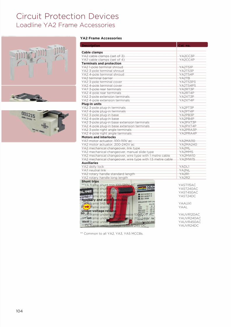
7/21/2019 TE Dorman Smith Product Portofolio 2011
http://slidepdf.com/reader/full/te-dorman-smith-product-portofolio-2011 106/182
104
** Common to all YA2, YA3, YA5 MCCBs.
Circuit Protection DevicesLoadline YA2 Frame Accessories
Cable clamps
YA2 cable clamps (set of 3) YA2CC3PYA2 cable clamps (set of 4) YA2CC4PTerminals and protectionYA2 1-pole terminal shroud YA2TS1PYA2 3-pole terminal shroud YA2TS3PYA2 4-pole terminal shroud YA2TS4PYA2 terminal barrier YA2TBYA2 3-pole terminal cover YA2TS3P3YA2 4-pole terminal cover YA2TS4PSYA2 3-pole rear terminals YA2RT3PYA2 4-pole rear terminals YA2RT4PYA2 3-pole extension terminals YA2XT3PYA2 4-pole extension terminals YA2XT4PPlug-in unitsYA2 3-pole plug-in terminals YA2PT3PYA2 4-pole plug-in terminals YA2PT4P
YA2 3-pole plug-in base YA2PB3PYA2 4-pole plug-in base YA2PB4PYA2 3-pole plug-in base extension terminals YA2PXT3PYA2 4-pole plug-in base extension terminals YA2PXT4PYA2 3-pole right angle terminals YA2PRA3PYA2 4-pole right angle terminals YA2PRA4PMotors and interlocksYA2 motor actuator, 100-110V ac YA2MA110YA2 motor actuator, 200-240V ac YA2MA240YA2 mechanical changeover, link type YA2MLYA2 mechanical changeover, manual slide type YA2MMSYA2 mechanical changeover, wire type with 1 metre cable YA2MW10YA2 mechanical changeover, wire type with 1.5 metre cable YA2MW15AuxiliariesYA2 dolly lock YADL1
YA2 neutral link YA2NLYA2 rotary handle standard length YA2R1YA2 rotary handle long length YA2R2Shunt trips**YA frame shunt trip 100-120V AC YAST115AC**YA frame shunt trip 200-240V AC YAST240AC**YA frame shunt trip 380-450V AC YAST450AC**YA frame shunt trip 24V DC YAST24DCAuxiliary and alarm switches**YA frame 1AB auxiliary switch YAAUX1**YA frame alarm switch YAALUnder-voltage release**YA frame under-voltage release 100-120V AC YAUVR120AC**YA frame under-voltage release 200-240V AC YAUVR240AC**YA frame under-voltage release 380-450V AC YAUVR450AC**YA frame under-voltage release 24V DC YAUVR24DC
Description Cat. no.
YA2 Frame Accessories
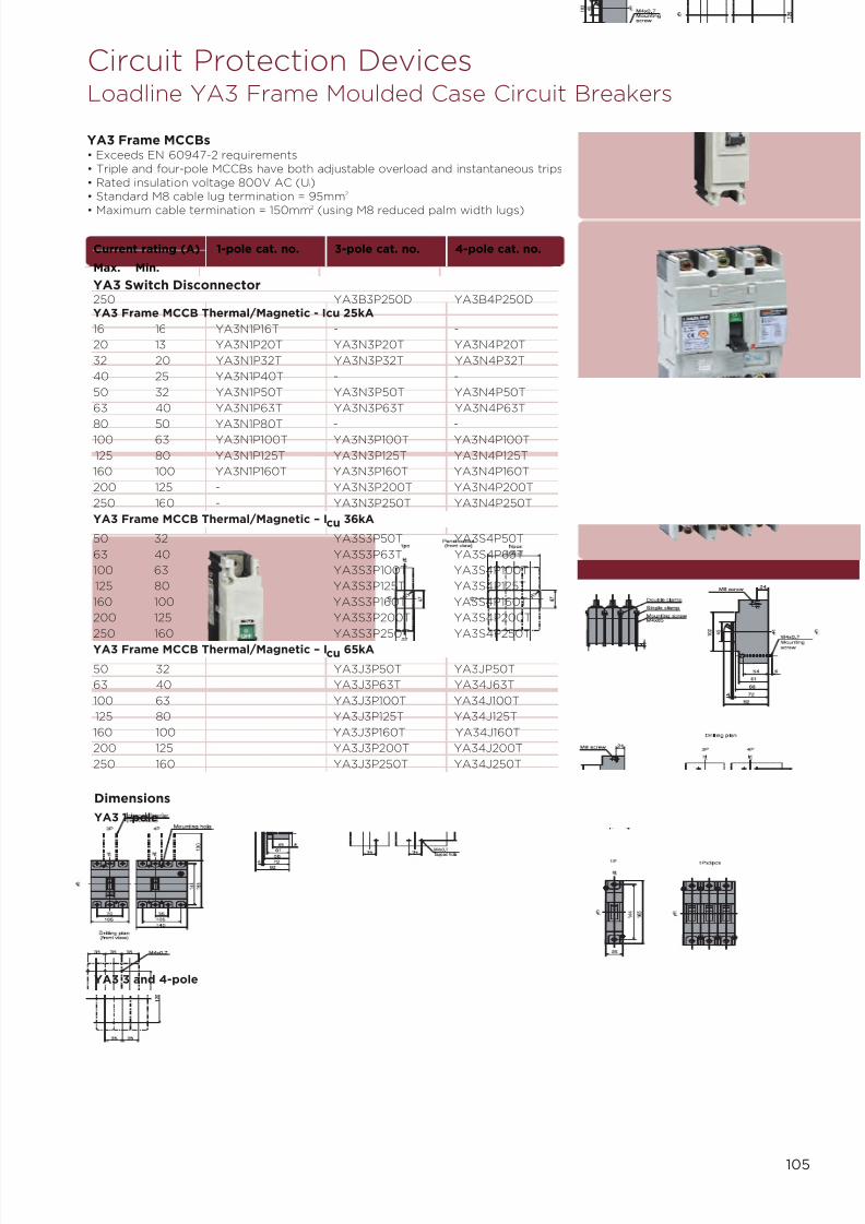
7/21/2019 TE Dorman Smith Product Portofolio 2011
http://slidepdf.com/reader/full/te-dorman-smith-product-portofolio-2011 107/182
105
YA3 Frame MCCBs• Exceeds EN 60947-2 requirements• Triple and four-pole MCCBs have both adjustable overload and instantaneous trips• Rated insulation voltage 800V AC (U i)• Standard M8 cable lug termination = 95mm 2
• Maximum cable termination = 150mm2
(using M8 reduced palm width lugs)
YA3 Switch Disconnector250 YA3B3P250D YA3B4P250DYA3 Frame MCCB Thermal/Magnetic - Icu 25kA
16 16 YA3N1P16T - -
20 13 YA3N1P20T YA3N3P20T YA3N4P20T
32 20 YA3N1P32T YA3N3P32T YA3N4P32T
40 25 YA3N1P40T - -
50 32 YA3N1P50T YA3N3P50T YA3N4P50T
63 40 YA3N1P63T YA3N3P63T YA3N4P63T
80 50 YA3N1P80T - -100 63 YA3N1P100T YA3N3P100T YA3N4P100T
125 80 YA3N1P125T YA3N3P125T YA3N4P125T
160 100 YA3N1P160T YA3N3P160T YA3N4P160T
200 125 - YA3N3P200T YA3N4P200T
250 160 - YA3N3P250T YA3N4P250T
YA3 Frame MCCB Thermal/Magnetic – Icu 36kA
50 32 YA3S3P50T YA3S4P50T
63 40 YA3S3P63T YA3S4P63T
100 63 YA3S3P100T YA3S4P100T
125 80 YA3S3P125T YA3S4P125T
160 100 YA3S3P160T YA3S4P160T
200 125 YA3S3P200T YA3S4P200T
250 160 YA3S3P250T YA3S4P250T
YA3 Frame MCCB Thermal/Magnetic – Icu 65kA
50 32 YA3J3P50T YA3JP50T
63 40 YA3J3P63T YA34J63T
100 63 YA3J3P100T YA34J100T
125 80 YA3J3P125T YA34J125T
160 100 YA3J3P160T YA34J160T
200 125 YA3J3P200T YA34J200T
250 160 YA3J3P250T YA34J250T
Current rating (A) 1-pole cat. no. 3-pole cat. no. 4-pole cat. no.
Max. Min.
Circuit Protection DevicesLoadline YA3 Frame Moulded Case Circuit Breakers
Dimensions
YA3 1-pole
YA3 3 and 4-pole
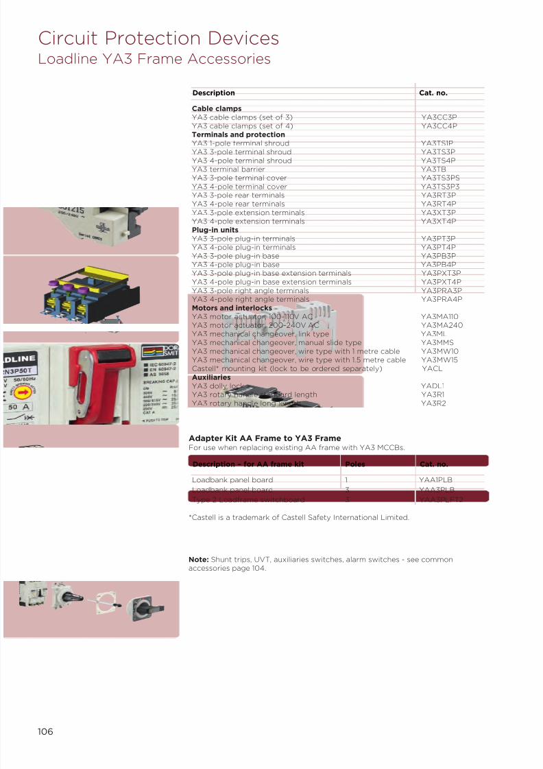
7/21/2019 TE Dorman Smith Product Portofolio 2011
http://slidepdf.com/reader/full/te-dorman-smith-product-portofolio-2011 108/182
106
Circuit Protection DevicesLoadline YA3 Frame Accessories
Cable clampsYA3 cable clamps (set of 3) YA3CC3PYA3 cable clamps (set of 4) YA3CC4P
Terminals and protectionYA3 1-pole terminal shroud YA3TS1PYA3 3-pole terminal shroud YA3TS3PYA3 4-pole terminal shroud YA3TS4PYA3 terminal barrier YA3TBYA3 3-pole terminal cover YA3TS3PSYA3 4-pole terminal cover YA3TS3P3YA3 3-pole rear terminals YA3RT3PYA3 4-pole rear terminals YA3RT4PYA3 3-pole extension terminals YA3XT3PYA3 4-pole extension terminals YA3XT4PPlug-in unitsYA3 3-pole plug-in terminals YA3PT3PYA3 4-pole plug-in terminals YA3PT4PYA3 3-pole plug-in base YA3PB3PYA3 4-pole plug-in base YA3PB4PYA3 3-pole plug-in base extension terminals YA3PXT3PYA3 4-pole plug-in base extension terminals YA3PXT4PYA3 3-pole right angle terminals YA3PRA3PYA3 4-pole right angle terminals YA3PRA4PMotors and interlocksYA3 motor actuator, 100-110V AC YA3MA110YA3 motor actuator, 200-240V AC YA3MA240YA3 mechanical changeover, link type YA3MLYA3 mechanical changeover, manual slide type YA3MMSYA3 mechanical changeover, wire type with 1 metre cable YA3MW10YA3 mechanical changeover, wire type with 1.5 metre cable YA3MW15Castell* mounting kit (lock to be ordered separately) YACLAuxiliariesYA3 dolly lock YADL1YA3 rotary handle standard length YA3R1
YA3 rotary handle long length YA3R2
Description Cat. no.
Adapter Kit AA Frame to YA3 FrameFor use when replacing existing AA frame with YA3 MCCBs.
Loadbank panel board 1 YAA1PLB
Loadbank panel board 3 YAA3PLB
Type 2 Loadframe switchboard 3 YAA3PLFT2
Description – for AA frame kit Poles Cat. no.
*Castell is a trademark of Castell Safety International Limited.
Note: Shunt trips, UVT, auxiliaries switches, alarm switches - see commonaccessories page 104.

7/21/2019 TE Dorman Smith Product Portofolio 2011
http://slidepdf.com/reader/full/te-dorman-smith-product-portofolio-2011 109/182
107
YA5 Frame MCCBs
• Exceeds EN60947-2 requirements• Triple and four-pole MCCBs have both adjustable overload and instantaneous trips• Rated insulation voltage 800V AC (U i)• Electronic MCCBs are Category B rated for discrimination
• No extension terminal bars supplied, see ‘Accessories’ if required• Standard M10 cable lug termination = 95mm2
• Maximum cable termination = 185mm2 (using M10 reduced palm width lugs)
YA5 Switch Disconnector
400 YA5B3P400D YA5B4P400D
YA5 Frame MCCB Thermal/Magnetic – Icu 25kA
250 157 YA5N3P250T YA5N4P250T
400 252 YA5N3P400T YA5N4P400T
YA5 Frame MCCB Thermal/Magnetic – Icu 50kA
250 157 YA5H3P250T YA5H4P250T400 252 YA5H3P400T YA5H4P400T
YA5 Frame MCCB Thermal/Magnetic – Icu 65kA
250 157 YA5J3P250T YA5J4P250T
400 252 YA5J3P400T YA5J4P400T
YA5 Frame MCCB Electronic – Icu 70kA
250 125 YA5K3P250E YA5K4P250E
400 200 YA5K3P400E YA5K4P400E
Current rating (A) 3-pole cat. no. 4-pole cat. no.
Max. Min.
Circuit Protection DevicesLoadline YA5 Frame Moulded Case Circuit Breakers
Dimensions
YA5 3 and 4-pole

7/21/2019 TE Dorman Smith Product Portofolio 2011
http://slidepdf.com/reader/full/te-dorman-smith-product-portofolio-2011 110/182
108
YA5 Frame MCCB Accessories
Cable clamps
YA5 cable clamps (set of 3) YA5CC3P
YA5 cable clamps (set of 4) YA5CC4P
Terminals and protection
YA5 3-pole terminal shroud YA5TS3P
YA5 4-pole terminal shroud YA5TS4P
YA5 terminal barrier YA5TB
YA5 3-pole terminal cover YA5TC3P
YA5 4-pole terminal cover YA5TC4P
YA5 3-pole rear terminals YA5RT3P
YA5 4-pole rear terminals YA5RT4P
YA5 3-pole extension terminals YA5XT3P
YA5 4-pole extension terminals YA5XT4P
Plug-in units
YA5 3-pole plug-in terminals YA5PT3P
YA5 4-pole plug-in terminals YA5PT4PYA5 3-pole plug-in base YA5PB3P
YA5 4-pole plug-in base YA5PB4P
YA5 3-pole plug-in base extension terminals YA5PXT3P
YA5 4-pole plug-in base extension terminals YA5PXT4P
YA5 3-pole right angle terminals YA5PRA3P
YA5 4-pole right angle terminals YA5PRA4P
Motors and interlocks
YA5 motor actuator, 100-110V ac YA5MA110
YA5 motor actuator, 200-240V ac YA5MA240
YA5 mechanical changeover, link type YA5ML
YA5 mechanical changeover, manual slide type YA5MMS
YA5 mechanical changeover, wire type with 1 metre cable YA5MW10
YA5 mechanical changeover, wire type with 1.5 metre cable YA5MW15
Auxiliaries
YA5 dolly lock YA5DL
YA5 neutral link YA5NL
YA5 rotary handle standard length YA5R1
YA5 rotary handle long length YA5R2
Description Cat. no.
Note: Shunt trips, UVT and auxiliaries - see common accessories page 104.
Circuit Protection DevicesLoadline YA5 Frame Accessories

7/21/2019 TE Dorman Smith Product Portofolio 2011
http://slidepdf.com/reader/full/te-dorman-smith-product-portofolio-2011 111/182
109
Circuit Protection DevicesLoadline Y6 Frame Moulded Case Circuit Breakers
Y6 Frame MCCBs
• Exceeds the requirements of EN 60947-2• Rated insulation voltage 690V AC (U i)• Electronic MCCBs have adjustable long, short and instantaneous trip functions• Electronic MCCBs are Category B rated for discrimination
• Standard M12 cable termination = 240mm2
• Extension terminal bars to be ordered separately when not used in conjunctionwith Dorman Smith steel work - Y6XT4P (2 required)
Y6 Frame Switch Disconnector630 Y6B3P630D Y6B4P630D
800 Y6B3P800D Y6B4P800DY6 Frame MCCB Thermal/Magnetic – Icu 50kA
400 250 Y6H3P400T5 Y6H4P400T5
630 400 Y6H3P630T5 Y6H4P630T5
800 500 Y6H3P800T5 Y6H4P800T5
Y6 Frame MCCB Thermal/Magnetic – Icu 85kA
400 250 Y6K3P400T5 Y6K4P400T5
630 400 Y6K3P630T5 Y6K4P630T5
800 500 Y6K3P800T5 Y6K4P800T5
Y6 Frame MCCB Electronic – Icu 50kA
630 315 Y6H3P630E Y6H4P630E
800 400 Y6H3P800E Y6H4P800E
Y6 Frame MCCB Electronic – Icu 65kA
630 315 Y6J3P630E Y6J4P630E
800 400 Y6J3P800E Y6J4P800E
Current rating (A) 3-pole cat. no. 4-pole cat. no.
Max. Min.
Dimensions
Y6

7/21/2019 TE Dorman Smith Product Portofolio 2011
http://slidepdf.com/reader/full/te-dorman-smith-product-portofolio-2011 112/182
110
Terminal covers 3-pole
Terminal shroud (set of 1) Y6TS3P
Interphase barriers (set of 2) Y5TB3P
Terminal covers 4-pole
Terminal shroud (set of 1) Y6TS4P
Interphase barriers (set of 3) Y5TB4P
Terminations 3/4-pole
Cable clamps 2 x 185mm2 only Y6CC4P
Locking devices
Dolly padlock device Y6DL
Castell* lock (DS1 direct mounting) Y6CLDS1
Castell* lock (DS2 direct mounting) Y6CLDS2
Castell* lock door-mounted cam for shaft only Y5DCLCAM
Shunt trips
Shunt 24V dc Y6ST24DC
Shunt 100-115V ac Y6ST115AC
Shunt 200-480V ac Y6ST480ACUndervoltage release
UVR 24V dc Y6UVR24DC
UVR 100-120V ac Y6UVR120AC
UVR 200-240V ac Y6UVR240AC
UVR 380-450V ac Y6UVR450AC
Motors and interlocks
Motor actuator, 100-110V ac Y6MA110
Motor actuator, 200-240V ac Y6MA240
Changeover, rocker type Y6MR
Changeover, manual slide type Y6MMS
Changeover, wire type with 1 metre cable Y6MW10
Changeover, wire type with 1.5 metre cable Y6MW15
Auxiliary switches
1AB auxiliary switch Y6AUX1
2AB auxiliary switch Y6AUX2
Alarm switch + 1 auxiliary Y6AUXAL
Neutral link
Y6 Neutral link Y6NL
Rotary handles
Standard length Y6RH1
Long length Y6RH2
Cover flange Y5CF
Handle extension Y6HE
Description Cat. no.
*Castell is a trademark of Castell Safety International Limited.
Circuit Protection DevicesLoadline Y6 Frame Accessories

7/21/2019 TE Dorman Smith Product Portofolio 2011
http://slidepdf.com/reader/full/te-dorman-smith-product-portofolio-2011 113/182
111
Circuit Protection DevicesLoadline Y6 Frame Moulded Case Circuit Breakers
Changeover UnitsThe changeover pairs are four-pole units fitted with mechanical and electricalinterlocking mounted on a back plate. Both devices have a motor actuator and areterminated for front access. All changeover pairs utilise the Y6 range of breakers.Each breaker is fitted with:
1 - Shunt trip 240V AC - Electrical interlock1 - AB auxiliary switch - to indicate MCCB status1 - Alarm switch - for auto reset1 - Motor operator spring charged 240V AC - to drive MCCB1 - Mechanical interlock (rear)
400A Y6AC400
630A Y6AC630
800A Y6AC800
Rating (A) Cat. no.
Remote Operation
Changeover Unit Dimensions (mm)
Y Frame Changeover Unit
Remote Operation
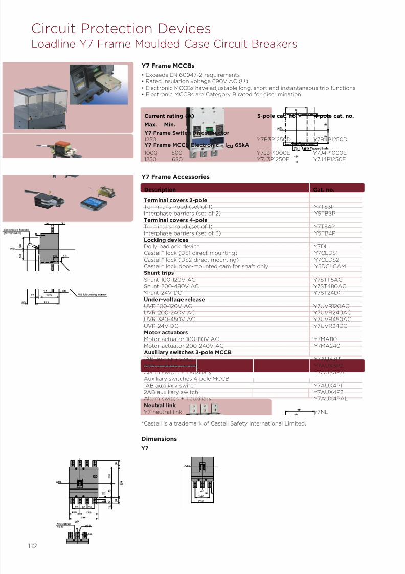
7/21/2019 TE Dorman Smith Product Portofolio 2011
http://slidepdf.com/reader/full/te-dorman-smith-product-portofolio-2011 114/182
112
Circuit Protection DevicesLoadline Y7 Frame Moulded Case Circuit Breakers
Y7 Frame Accessories
Terminal covers 3-poleTerminal shroud (set of 1) Y7TS3P
Interphase barriers (set of 2) Y5TB3P
Terminal covers 4-pole
Terminal shroud (set of 1) Y7TS4P
Interphase barriers (set of 3) Y5TB4P
Locking devices
Dolly padlock device Y7DL
Castell* lock (DS1 direct mounting) Y7CLDS1
Castell* lock (DS2 direct mounting) Y7CLDS2
Castell* lock door-mounted cam for shaft only Y5DCLCAM
Shunt trips
Shunt 100-120V AC Y7ST115AC
Shunt 200-480V AC Y7ST480AC
Shunt 24V DC Y7ST24DC
Under-voltage releaseUVR 100-120V AC Y7UVR120AC
UVR 200-240V AC Y7UVR240AC
UVR 380-450V AC Y7UVR450AC
UVR 24V DC Y7UVR24DC
Motor actuators
Motor actuator 100-110V AC Y7MA110
Motor actuator 200-240V AC Y7MA240
Auxiliary switches 3-pole MCCB
1AB auxiliary switch Y7AUX3P1
2AB auxiliary switch Y7AUX3P2
Alarm switch + 1 auxiliary Y7AUX3PAL
Auxiliary switches 4-pole MCCB
1AB auxiliary switch Y7AUX4P1
2AB auxiliary switch Y7AUX4P2
Alarm switch + 1 auxiliary Y7AUX4PALNeutral link
Y7 neutral link Y7NL
Description Cat. no.
Y7 Frame MCCBs
• Exceeds EN 60947-2 requirements• Rated insulation voltage 690V AC (U i)• Electronic MCCBs have adjustable long, short and instantaneous trip functions• Electronic MCCBs are Category B rated for discrimination
Y7 Frame Switch Disconnector
1250 Y7B3P1250D Y7B4P1250DY7 Frame MCCB Electronic – Icu 65kA
1000 500 Y7J3P1000E Y7J4P1000E
1250 630 Y7J3P1250E Y7J4P1250E
*Castell is a trademark of Castell Safety International Limited.
Current rating (A) 3-pole cat. no. 4-pole cat. no.
Max. Min.
Dimensions
Y7

7/21/2019 TE Dorman Smith Product Portofolio 2011
http://slidepdf.com/reader/full/te-dorman-smith-product-portofolio-2011 115/182
113
Circuit Protection DevicesLoadline Y8 Frame Moulded Case Circuit Breakers
Y8 Frame MCCBs
• Exceeds EN 60947-2 requirements• Rated insulation voltage 690V AC (U i)• Electronic MCCBs have adjustable long, short and instantaneous trip functions• Electronic MCCBs are Category B rated for discrimination
Y8 Frame Switch Disconnectors1600 Front terminals Y8B3P1600D Y8B4P1600D1600 Rear terminals Y8B3P1600DR -1600 Draw out Y8B3P1600DDO -Y8 Frame MCCB Electronic – Icu 85kA
1600 Front terminals Y8K3P1600E Y8K4P1600E1600 Rear terminals Y8K3P1600ER N/A1600 Ground fault Y8K3P1600EG N/A
Current rating (A) Type 3-pole cat. no. 4-pole cat. no.
Y8 Frame Accessories
Terminal covers 3-poleTerminal shroud (set of 1) Y7TS3PInterphase barriers (set of 2) Y5TB3PTerminal covers 4-poleTerminal shroud (set of 1) Y7TS4PInterphase barriers (set of 3) Y5TB4PLocking devicesDolly padlock device Y7DLCastell* lock (DS1 direct mounting) Y7CL
Castell* lock (DS2 direct mounting) Y7CLDS2Castell* lock door-mounted cam for shaft only Y5DCLCAMShunt tripsShunt 100-120V AC Y7ST115ACShunt 200-480V AC Y7ST480AC
Shunt 24V DC Y7ST24DCUnder-voltage releaseUVR 100-120V AC Y7UVR120ACUVR 200-240V AC Y7UVR240ACUVR 380-450V AC Y7UVR450ACUVR 24V DC Y7UVR24DCMotor actuatorsMotor actuator 100-110V AC Y7MA110Motor actuator 200-240V AC Y7MA240Auxiliary switches 3-pole MCCB1AB auxiliary switch Y7AUX3P12AB auxiliary switch Y7AUX3P2Alarm switch + 1 auxiliary Y7AUX3PALAuxiliary switches 4-pole MCCB1AB auxiliary switch Y7AUX4P12AB auxiliary switch Y7AUX4P2
Alarm switch + 1 auxiliary Y7AUX4PALNeutral linkY7 neutral link Y7NL
Description Cat. no.
*Castell is a trademark of Castell Safety International Limited.
Dimensions
Y8
Mounting hole
Conductoroverlapmax.
o13
Extension handle(removable)
Insulator
Mounting angle
M8 Mounting screw
Mounting angle
ø970
4P
3P
HL
1 8 4
1 5 m a x
1 5 m a x
1 5 4
1 7 0
1 4 0
3 7 0
1 0 0
1 0 0
3 0
188
20
17
80 191
20 11
28
46
140
70
105
280
175
70 70
210
70 70
45
2 0
3 2
1 5
2 0 0
1 7
0
4P3P HL HL
ASLASL ASL
N
o12
3 0
6 5 1 0 0
6 0
70
85
115
130
15
15
MIN EARTHED BOUNDARY MIN EARTHED BOUNDARY
7 0 . 0
0
4 0 . 0
0
30.00 30.00

7/21/2019 TE Dorman Smith Product Portofolio 2011
http://slidepdf.com/reader/full/te-dorman-smith-product-portofolio-2011 116/182
114
Circuit Protection DevicesLoadmaster Miniature Circuit Breakers
10 LM10 -
20 LM20 LM3P2030 LM30 LM3P30
40 LM40 -
50 - -
60 LM60 -
Current rating (A) 1-pole cat. no. 3-pole cat. no.
Loadmaster MCBs
100 - LW3
Current rating (A) 1-pole cat. no. 3-pole cat. no.
Loadmaster Isolators
Loadmaster Accessories
Mounting bracket for MCB/isolator 2-pole LMMB2
Mounting bracket for MCB/isolator 3-pole LMMB3
Description Cat. no.

7/21/2019 TE Dorman Smith Product Portofolio 2011
http://slidepdf.com/reader/full/te-dorman-smith-product-portofolio-2011 117/182

7/21/2019 TE Dorman Smith Product Portofolio 2011
http://slidepdf.com/reader/full/te-dorman-smith-product-portofolio-2011 118/182
116
Modular DevicesDSPE Range Surge Protector Series
DSPE 600 Series• Low “let through” voltage of 600 volts• Two stage (redundant) protection, with pre-failure indication• Site fault condition indicator• Remote Monitoring Unit is provided with a 1 metre cable and appropriate plug
and socket connectors (other lengths are available on request)• Easy installation and field serviceability• Compact size and small footprint
Dimensions
70,00
1 6 5
, 0 0
10,00
1 7 7
, 0 0
1 8 6
, 5 0
Specification and Dimensions
Voltage rating (Nominal), Un 400V rms
Max. continuous operating voltage, Uc L-N 300V rms
L-L 500V rms
Maximum load current rating Unlimited (parallel connection)
Maximum surge current (8/20µs), Imax 30kA per phase
Response time <10 ns
Power consumption (nominal) 18mA per phase
Leakage current to earth 600µA
Terminals 16mm2 max - line, neutral, earth
2.5mm2 max - remote signalling
Remote signalling terminals Rated at 230V rms 0.2A or30V DC 2A
Operating temperature -40° to +70° Celsius
Light emitting diodes status indication Green: full protection
Red & green: reduced protection
Red - no protection
Case Steel - epoxy paint
Type (EN 61643-11) 2
Dimensions (mm) L 176
W 110
D 72
Weight (g) 1110
DSPM Surge Protectors Cat. no.
30kA 2-stage, 3-pole surge protector DSPE60030kA 2-stage, 3-pole surge protector, remote terms & monitoring DSPE600R30kA 2-stage, 3-pole surge protector with aux contact DSPE600NEnclosure for DSP3 surge protection units 2IP-7-0244(240mm (h) x 190mm (w) x 90mm (d))
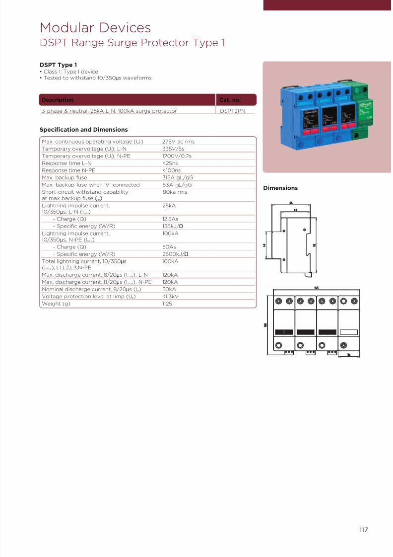
7/21/2019 TE Dorman Smith Product Portofolio 2011
http://slidepdf.com/reader/full/te-dorman-smith-product-portofolio-2011 119/182
117
Modular DevicesDSPT Range Surge Protector Type 1
DSPT Type 1• Class 1; Type I device• Tested to withstand 10/350µs waveforms
Dimensions
Specification and Dimensions
Max. continuous operating voltage (Uc) 275V ac rms
Temporary overvoltage (Ut), L-N 335V/5s
Temporary overvoltage (Ut), N-PE 1200V/0.2s
Response time L-N <25ns
Response time N-PE <100ns
Max. backup fuse 315A gL/gG
Max. backup fuse when ‘V’ connected 63A gL/gG
Short-circuit withstand capability 80ka rmsat max backup fuse (Ip)
Lightning impulse current, 25kA10/350µs, L-N (Iimp)
- Charge (Q) 12.5As
- Specific energy (W/R) 156kJ/Ω
Lightning impulse current, 100kA10/350µs, N-PE (Iimp)
- Charge (Q) 50As
- Specific energy (W/R) 2500kJ/Ω
Total lightning current, 10/350µs 100kA(Itotal), L1,L2,L3,N-PE
Max. discharge current, 8/20µs (Imax), L-N 120kA
Max. discharge current, 8/20µs (Imax), N-PE 120kA
Nominal discharge current, 8/20µs (In) 50kAVoltage protection level at Iimp (Up) <1.3kV
Weight (g) 1125
Description Cat. no.
3-phase & neutral, 25kA L-N, 100kA surge protector DSPT3PN
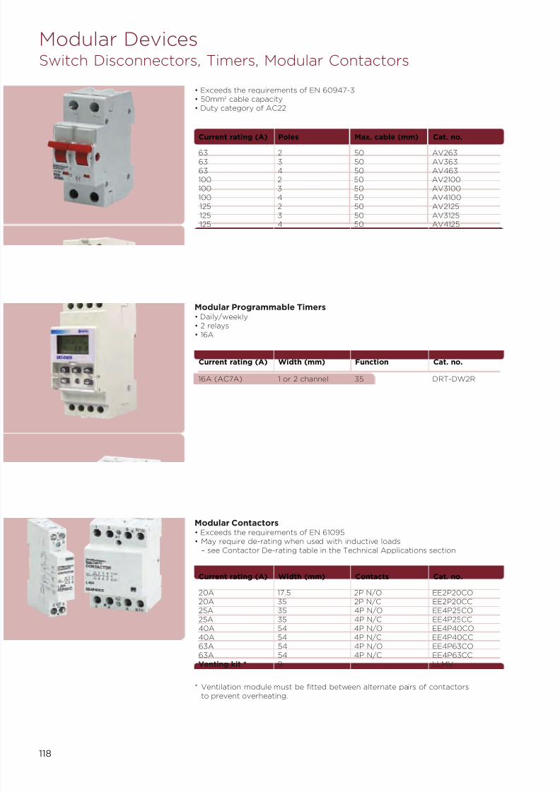
7/21/2019 TE Dorman Smith Product Portofolio 2011
http://slidepdf.com/reader/full/te-dorman-smith-product-portofolio-2011 120/182
118
Modular DevicesSwitch Disconnectors, Timers, Modular Contactors
63 2 50 AV26363 3 50 AV36363 4 50 AV463100 2 50 AV2100100 3 50 AV3100100 4 50 AV4100125 2 50 AV2125125 3 50 AV3125125 4 50 AV4125
Current rating (A) Poles Max. cable (mm) Cat. no.
• Exceeds the requirements of EN 60947-3• 50mm2 cable capacity• Duty category of AC22
Modular Contactors• Exceeds the requirements of EN 61095• May require de-rating when used with inductive loads
– see Contactor De-rating table in the Technical Applications section
Modular Programmable Timers• Daily/weekly• 2 relays• 16A
16A (AC7A) 1 or 2 channel 35 DRT-DW2R
Current rating (A) Width (mm) Function Cat. no.
20A 17.5 2P N/O EE2P20CO20A 35 2P N/C EE2P20CC25A 35 4P N/O EE4P25CO25A 35 4P N/C EE4P25CC40A 54 4P N/O EE4P40CO40A 54 4P N/C EE4P40CC63A 54 4P N/O EE4P63CO63A 54 4P N/C EE4P63CCVenting kit * 9 - LLMV
Current rating (A) Width (mm) Contacts Cat. no.
* Ventilation module must be fitted between alternate pairs of contactorsto prevent overheating.
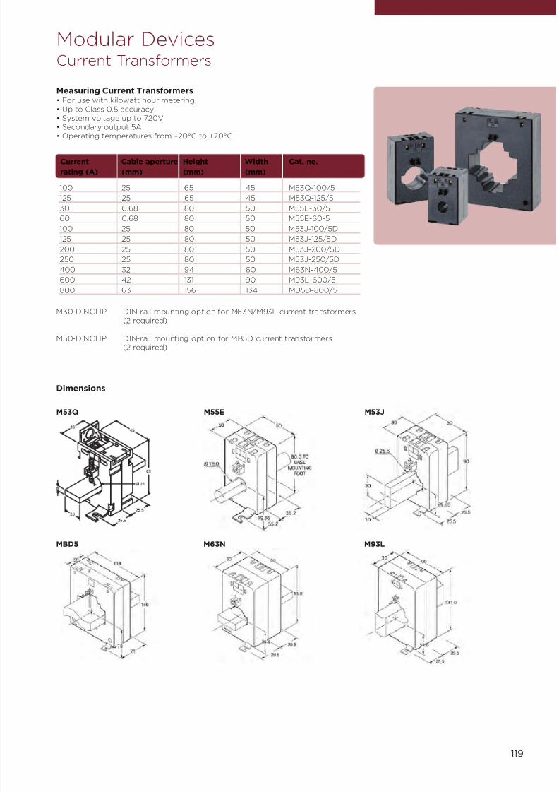
7/21/2019 TE Dorman Smith Product Portofolio 2011
http://slidepdf.com/reader/full/te-dorman-smith-product-portofolio-2011 121/182
Modular DevicesCurrent Transformers
Measuring Current Transformers• For use with kilowatt hour metering• Up to Class 0.5 accuracy• System voltage up to 720V• Secondary output 5A
• Operating temperatures from –20°C to +70°C
100 25 65 45 M53Q-100/5
125 25 65 45 M53Q-125/5
30 0.68 80 50 M55E-30/5
60 0.68 80 50 M55E-60-5
100 25 80 50 M53J-100/5D
125 25 80 50 M53J-125/5D
200 25 80 50 M53J-200/5D
250 25 80 50 M53J-250/5D
400 32 94 60 M63N-400/5
600 42 131 90 M93L-600/5
800 63 156 134 MB5D-800/5
Current Cable aperture Height Width Cat. no.
rating (A) (mm) (mm) (mm)
M30-DINCLIP DIN-rail mounting option for M63N/M93L current transformers(2 required)
M50-DINCLIP DIN-rail mounting option for MB5D current transformers(2 required)
Dimensions
M55EM53Q M53J
M63NMBD5 M93L
119
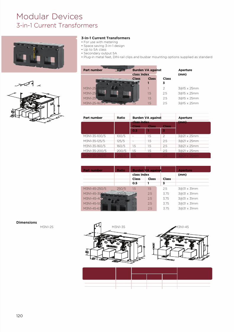
7/21/2019 TE Dorman Smith Product Portofolio 2011
http://slidepdf.com/reader/full/te-dorman-smith-product-portofolio-2011 122/182
M3N1-25 M3N1-45
Dimensions
M3N1-35
3-in-1 Current Transformers• For use with metering• Space saving 3-in-1 design• Up to 5A class• Secondary output 5A
• Plug-in metal feet, DIN-rail clips and busbar mounting options supplied as standard
Part number Ratio Burden VA against Aperture
class index (mm)
Class Class Class
0.5 1 3
M3N1-25-60/5 60/5 - 1 2 3@15 x 25mm
M3N1-25-100/5 100/5 - 1.5 2.5 3@15 x 25mm
M3N1-25-125/5 125/5 - 1.5 2.5 3@15 x 25mm
M3N1-25-160/5 160/5 1.5 1.5 2.5 3@15 x 25mm
Part number Ratio Burden VA against Aperture
class index (mm)
Class Class Class
0.5 1 3
M3N1-35-100/5 100/5 - 1.5 2 3@21 x 25mm
M3N1-35-125/5 125/5 - 1.5 2.5 3@21 x 25mm
M3N1-35-160/5 160/5 1.5 1.5 2.5 3@21 x 25mm
M3N1-35-200/5 200/5 1.5 1.5 2.5 3@21 x 25mm
M3N1-35-250/5 250/5 1.5 1.5 2.5 3@21 x 25mm
Part number Ratio Burden VA against Aperture
class index (mm)Class Class Class
0.5 1 3
M3N1-45-250/5 250/5 1.5 1.5 2.5 3@31 x 31mm
M3N1-45-300/5 300/5 2.5 2.5 3.75 3@31 x 31mm
M3N1-45-400/5 400/5 2.5 2.5 3.75 3@31 x 31mm
M3N1-45-500/5 500/5 2.5 2.5 3.75 3@31 x 31mm
M3N1-45-630/5 630/5 2.5 2.5 3.75 3@31 x 31mm
Modular Devices3-in-1 Current Transformers
120

7/21/2019 TE Dorman Smith Product Portofolio 2011
http://slidepdf.com/reader/full/te-dorman-smith-product-portofolio-2011 123/182
121
A range of split core current transformers that offers a costeffective and efficient method by which the current can bemeasured without the need to break the conductor, therebyreducing installation and commissioning time.
Accuracy Class
Dimension Case 1 Case 2 Case 3 Case 4
A 20 50 80 80
B 30 80 80 120
C 51 78 108 108
D 89 114 144 144
E 111 145 145 185
F 34 32 32 32G 47 32 32 32
H 40 32 32 32
I 32 33 33 33
Weight (Kg) 0.75 0.90 1.05 1.25
Units of measurement – mm
Part number Ratio Burden VA against class index Aperture
(mm)
0.5 1 3
SC1-100/5A 100/5A - - 1.5 20 x 30
SC1-150/5A 150/5A - - 2 20 x 30
SC1-200/5A 200/5A - 1.5 2.5 20 x 30
SC1-250/5A 250/5A - 2 4 20 x 30
SC1-300/5A 300/5A 1.5 4 6 20 x 30
SC1-400/5A 400/5A 2.5 6 10 20 x 30
SC2-250/5A 250/5A 1 2 4 50 x 80
SC2-300/5A 300/5A 1.5 3 6 50 x 80
SC2-400/5A 400/5A 1.5 3 10 50 x 80SC3-250/5A 250/5A 1 2 4 80 x 80
SC3-300/5A 300/5A 1.5 3 6 80 x 80
SC3-400/5A 400/5A 1.5 3 10 80 x 80
SC3-500/5A 500/5A 2.5 5 15 80 x 80
SC3-600/5A 600/5A 2.5 5 15 80 x 80
SC3-750/5A 750/5A 3 6 20 80 x 80
SC3-800/5A 800/5A 3 7.5 20 80 x 80
SC3-1000/5A 1000/5A 5 10 20 80 x 80
SC4-500/5A 500/5A - 4 12.5 80 x 120
SC4-600/5A 600/5A - 5 15 80 x 120
SC4-750/5A 750/5A 2.5 6 17.5 80 x 120
SC4-800/5A 800/5A 3 7.5 20 80 x 120
SC4-1000/5A 1000/5A 5 10 20 80 x 120
SC4-1200/5A 1200/5A 6 12.5 25 80 x 120
SC4-1250/5A 1250/5A 7.5 15 30 80 x 120
SC4-1500/5A 1500/5A 8 17 30 80 x 120
SC4-1600/5A 1600/5A 8 17 30 80 x 120
C a s e 1
C
a s e 2
C a s e 3
C a
s e 4
Modular DevicesSplit Core Current Transformers
Dimensions

7/21/2019 TE Dorman Smith Product Portofolio 2011
http://slidepdf.com/reader/full/te-dorman-smith-product-portofolio-2011 124/182
122
• Precision digital protection relay• Adjustable sensitivity of 30mA to 10A• Adjustable time delay from 0 to 10 seconds• Double-pole relay contacts 8A, 250V• Supply voltage 100-250V AC/DC (50/100Hz)
50 100-250 AC/DC ELR1
Frequency (Hz) Auxiliary supply (V) Cat. no.
Earth Leakage RelayDIN-rail Mounted
110.0mm 4.32"
73.0mm 2.87"
33.0mm 1.3"
48.0mm 1.89"
71.0mm
2.79"
6 2 . 5 m m
2 . 4
6 "
9 0 . 5 m m
3 . 5
6 "
4 6 . 0 m m
1 . 8 7 "
Remoteresetswitch
FusedAuxiliarysupply
The equipment groundingconductor must bypass the CT
CommissioningMeter
Link to energiseon trip
GND
Relay 1 Relay 2
Connections
Specification
Measuring input From core balanced current transformer
Overload 20 x nominal for 1 second
Frequency 50Hz or 60Hz ±10%
Auxiliary voltage 100-250V ac and dc
Auxiliary burden Less than 1.5 Watts
Trip current settings Selectable 30mA, 100mA, 200mA, 300mA, 500mA,
1A, 2A, 3A, 5A, 10ATrip accuracy 50% <trip point current
<100% in accordance with IEC 1543
Trip response time <40ms (at 5 x rated trip current, ignoring theselected time delay)
Time delay set points Selectable 0ms, 50ms, 100ms, 150ms, 200ms,300ms, 400ms, 500ms, 600ms, 700ms, 800ms,900ms, 1 second, 2 seconds, 5 seconds, 10 seconds.When 30mA leakage is selected, the time delay isdisabled
Indication 5 yellow LED bar graph for leakage levelsRed LED indicated trip functionGreen LED indicated auxiliary power presenceRed LED pre-alarm indication (SPCO version only)
Relay contacts Standard: 2-pole change over
Option: 2 1-pole change over (pre-alarm andmain alarm)
Relay contact rating 8 amps at 250V ac8 amps at 30V dc resistive
Relay mechanical life >100,000 operations
Analogue output 0 to 1mA = 0 to 100% of selected tripping level.Compliance 1V, accuracy 10%
Enclosure style DIN 43880, rail width 70mm
Compliant with EMC and LVD, UL 3111-1 File No: E203000, CSA22.2/1010.1-92 BSEN 50081-1, BSEN 50082-2, IEC60255-22-1 (BS5992), IEC 60255-11, BSEN 61543 (IEC1543), BSEN 61010 (IEC 1010), EN 60068 (IEC 68)
Material Flame retardant UL94V0
Terminals 1 to 4mm2 solid or stranded conductors.IP20 protection
Operating temperature –10°C to +60°C
Storage temperature –20°C to +70°C
Relative humidity <95% non condensing
Weight <250g
Dimensions 71mm wide x 90.5mm high x 73mm deep 2.79" widex 3.56" high x 2.87" deep
Dimensions
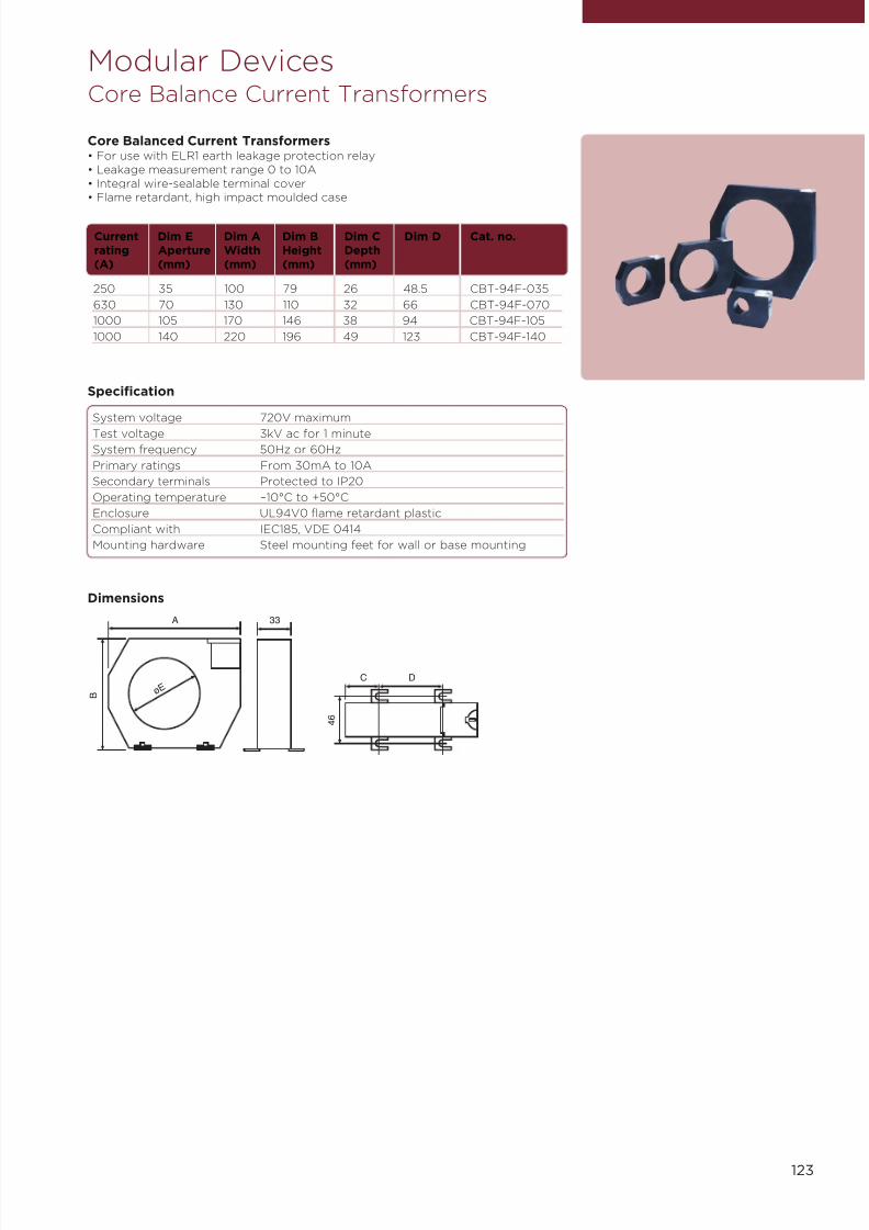
7/21/2019 TE Dorman Smith Product Portofolio 2011
http://slidepdf.com/reader/full/te-dorman-smith-product-portofolio-2011 125/182
123
Modular DevicesCore Balance Current Transformers
Core Balanced Current Transformers• For use with ELR1 earth leakage protection relay• Leakage measurement range 0 to 10A• Integral wire-sealable terminal cover• Flame retardant, high impact moulded case
250 35 100 79 26 48.5 CBT-94F-035
630 70 130 110 32 66 CBT-94F-070
1000 105 170 146 38 94 CBT-94F-105
1000 140 220 196 49 123 CBT-94F-140
Current Dim E Dim A Dim B Dim C Dim D Cat. no.rating Aperture Width Height Depth(A) (mm) (mm) (mm) (mm)
Specification
System voltage 720V maximum
Test voltage 3kV ac for 1 minute
System frequency 50Hz or 60Hz
Primary ratings From 30mA to 10A
Secondary terminals Protected to IP20
Operating temperature –10°C to +50°C
Enclosure UL94V0 flame retardant plastic
Compliant with IEC185, VDE 0414
Mounting hardware Steel mounting feet for wall or base mounting
A
ø E B
33
DC
4 6
Dimensions

7/21/2019 TE Dorman Smith Product Portofolio 2011
http://slidepdf.com/reader/full/te-dorman-smith-product-portofolio-2011 126/182
124
Modular DevicesIntegra Ci1 Energy Meter
The Integra Ci1 energy meter is specially designed and developedas a cost effective Watt hour and VAr hour meter to complementthe current Integra Ci digital metering system (dms). The IntegraCi1 self-contained 96mm DIN panel mounted Watt hour, VAr hour
meter measures the real consumption of active and reactiveenergy to Class 1.0 accuracy.
The backlit LCD screen displays 8 character counter indicating Watt hour or VArhour units. The optional modules enables transfer of energy measurements tobuilding management systems (BMS) via pulsed or digital communication options.
Programmable FunctionsIntegra Ci1 meter provides simple programming to suit single phase 2-wire, three-phase three wire and three-phase four-wire un-balanced system configurations,CT ratio settings and configuration of selected communication options. To preventunauthorised access to the product configuration settings, all set-up screensoffer password protection.
DisplayDirect access to display the programmed set CT ratio, Watt hours import andexport, VAr hours import and export and the phase sequence test routine for bothvoltage and current phases. During the accumulation of the Wh or VArh therunning icon will flash at a rate dependant on the displayed parameter.
Plug-in ModulesPlug-in modules allow to fit either maximum of two isolated pulsed output relaysor a RS485 communication module and one isolated pulsed output relay. Thecommunication output module can be programmed internally to respond either toModbus® RTU or Johnson Controls protocols.
Panel MountingIntegral retention clips allow fast, safe and secure panel mounting in variousmaterial thicknesses without the need for external screws or clips.
Description Part number
Integra Ci1 base unit with pulse output CI1-01-PUL
Options
Optional plug-in pulse output module CI-PUL-01
Optional RS485 Modbus plug-in module CI-MOD-01
Accessories
IP65 protective cover 3G36502
IP54 panel gasket 3C34501
Product Code
Parameters
Button Screen Parameters
CT 1 CT ratio
Wh 2 IMPORT Wh3 EXPORT Wh
VArh 4 IMPORT VArh5 EXPORT VArh
TEST 6 Phase sequencediagnostic
Running icon indicates Whand VAhr accumulation.
53.00
77.50
Dimensions

7/21/2019 TE Dorman Smith Product Portofolio 2011
http://slidepdf.com/reader/full/te-dorman-smith-product-portofolio-2011 127/182
125
The Integra Ci3 digital metering system (dms) represents the firstmodel of a new generation of digital metering systems designedto complement the current Crompton Instruments Integra series.
The Integra Ci3 meter is an accurate and cost effective solutionfor measurement and display of all major electrical and powerquality parameters.
Designed, developed and manufactured in the UK, the Integra Ci3dms builds on Crompton Instruments’ long established reputationfor metering product quality.
The product features a DIN 96 panel mounted enclosure, backlit LCD screen anduser programmable CT ratios, all accessible via an intuitive user interface. IntegraCi3 dms measures 17 electrical parameters including total harmonic distortion(THD) up to the 31st harmonic.
Programmable FunctionsIntegra Ci3 dms is programmable to suit single-phase two-wire, three-phasethree-wire and three-phase four-wire system configurations. Programmable CTratios enable to display any current range.
DisplayThe parameters can be viewed on a backlit LCD screen. The 15 screens areaccessible via four buttons on the front panel allowing to scroll between variousscreens making the navigation very user-friendly, intuitive and above all – simple.
Plug-in ModulesIntegra Ci3 dms offers two output ports at the rear of the product, to allow thefitting of either two isolated pulsed output relays or a RS485 communicationmodule such as Modbus® or Johnson Controls communication output. These areconfigurable via internal settings.
Panel MountingIntegral retention clips allow fast, safe and secure panel mounting in variousmaterial thicknesses without the need for external screws or clips.
Description Part number
Integra Ci3 base unit with pulse output CI3-01-PUL
Options
Optional plug-in pulse output module CI-PUL-01
Optional RS485 Modbus plug-in module CI-MOD-01
AccessoriesIP65 protective cover 3 G365 02IP54 panel gasket 3 C345 01
Product Code
Modular DevicesIntegra Ci3 Digital Metering System
Parameters
Button Screen Parameters
V/Hz 1 Volts L1 - N
Volts L2 - NVolts L3 - N
2 Volts L1 - L2
Volts L2 - L3Volts L3 - L1
3 Frequency4 Volts L1 - N THD%
Volts L2 - N THD%
Volts L3 - N THD%5 Volts L1 - L2 THD%
Volts L2 - L3 THD%Volts L3 - L1 THD%
A 1 Current L1Current L2Current L3
2 Neutral current3 L1 Current max
DemandL2 Current maxDemand
L3 Current maxDemand
4 Neutral current maxdemand
5 Current L1 THD%Current L2 THD%
Current L3 THD%
P/PF 1 kW
kVArkVA
2 kW Max demand3 Power factor
E 1 kWh2 kVArh
53.00
77.50
Dimensions
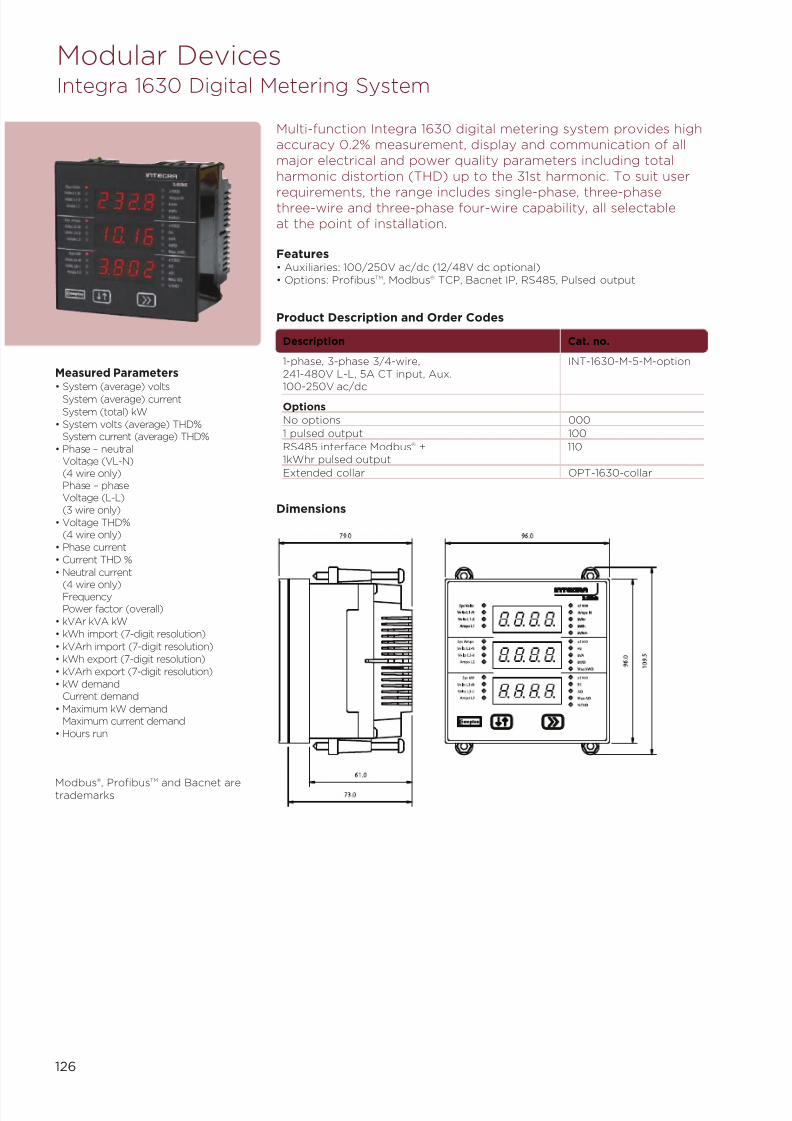
7/21/2019 TE Dorman Smith Product Portofolio 2011
http://slidepdf.com/reader/full/te-dorman-smith-product-portofolio-2011 128/182
126
Modular DevicesIntegra 1630 Digital Metering System
Multi-function Integra 1630 digital metering system provides highaccuracy 0.2% measurement, display and communication of allmajor electrical and power quality parameters including totalharmonic distortion (THD) up to the 31st harmonic. To suit user
requirements, the range includes single-phase, three-phasethree-wire and three-phase four-wire capability, all selectableat the point of installation.
Features• Auxiliaries: 100/250V ac/dc (12/48V dc optional)• Options: ProfibusTM, Modbus® TCP, Bacnet IP, RS485, Pulsed output
Product Description and Order Codes
Description Cat. no.
1-phase, 3-phase 3/4-wire, INT-1630-M-5-M-option241-480V L-L, 5A CT input, Aux.
100-250V ac/dcOptions
No options 000
1 pulsed output 100
RS485 interface Modbus® + 1101kWhr pulsed output
Extended collar OPT-1630-collar
Dimensions
Modbus®, ProfibusTM and Bacnet aretrademarks
Measured Parameters
• System (average) voltsSystem (average) current
System (total) kW• System volts (average) THD%
System current (average) THD%• Phase – neutral
Voltage (VL-N)(4 wire only)Phase – phaseVoltage (L-L)(3 wire only)
• Voltage THD%(4 wire only)
• Phase current• Current THD %
• Neutral current
(4 wire only)FrequencyPower factor (overall)
• kVAr kVA kW• kWh import (7-digit resolution)
• kVArh import (7-digit resolution)• kWh export (7-digit resolution)• kVArh export (7-digit resolution)• kW demand
Current demand
• Maximum kW demandMaximum current demand
• Hours run

7/21/2019 TE Dorman Smith Product Portofolio 2011
http://slidepdf.com/reader/full/te-dorman-smith-product-portofolio-2011 129/182
DRK-3PCT-400-D90
127
Self-contained energy metering system which is ideal forswitchgear, plant instrumentation and process control. The rangehas significant advantages over the traditional energy meters withpulsed outputs, communications and direct connection all
available as options.
Single-phase: 230V – CT Connected 5A
1-phase CT 5A – pulse output DRK-1PCT-240Pulsed output (Opto),Mechanical counter
Three-phase: 400V (+N) CT Connected 5A
3-phase 3 or 4-wire system, DRK-3PCT-4155A CT connected, pulsed output(Opto), mechanical counter
3-phase 3 or 4-wire system, DRK-3PCT-415-LCD5A CT connected, pulsed output(Opto), LCD screen
Single-phase: 230V – Direct Connected 63A
1-phase 230V–63A direct DRK-1P-230-D63connected, pulsed output (Opto)LCD screen
Three-phase: 230V (400V) – Direct Connected 100A
3-phase 230V L-N (400V L-L) DRK-3P-400-D100– 100A direct connected,
pulsed output (Opto), LCD screen
Description Cat. no.
Modular DevicesModular Devices Kilowatt Hour Energy Meters DIN-rail
Dimensions
DRK-1PCT-240 DRK-3PCT-415/ DRK-3PCT-415-LCD
DRK-1PCT-230-D63
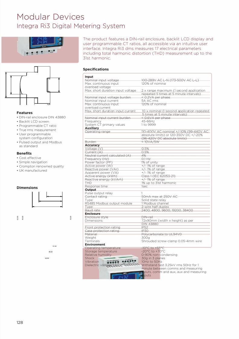
7/21/2019 TE Dorman Smith Product Portofolio 2011
http://slidepdf.com/reader/full/te-dorman-smith-product-portofolio-2011 130/182
128
Modular DevicesIntegra Ri3 Digital Metering System
The product features a DIN-rail enclosure, backlit LCD display anduser programmable CT ratios, all accessible via an intuitive userinterface. Integra Ri3 dms measures 17 electrical parametersincluding total harmonic distortion (THD) measurement up to the
31st harmonic.
Specifications
InputNominal input voltage 100-289V AC L-N (173-500V AC L-L)Max. continuous input 120% of nominaloverload voltageMax. short duration input voltage 2 x range maximum (1 second application
repeated 5 times at 5 minute intervals)Nominal input voltage burden < 0.2VA per phaseNominal input current 5A AC rmsMax. continuous input 120% of nominaloverload currentMax. short duration input current 10 x nominal (1 second application repeated
5 times at 5 minute intervals)
Nominal input current burden < 0.6VA per phaseFrequency 45-66HzSystem CT primary values 1 to 9999AuxiliaryOperating range 110-400V AC nominal +/-10% (99-440V AC
absolute limits) or 120-350V DC +/-20%(96-420V DC absolute limits)
Burden < 10VA/5WAccuracyVoltage (V) 0.5%Current (A) 0.5%Neutral current calculated (A) 4%Frequency (Hz) 0.1 HzPower factor (PF) 1% of unityActive power (W) +/- 1% of rangeReactive power (VAr) +/- 1% of rangeApparent power (VA) +/- 1% of range
Active energy (kWh) Class 1 (IEC 62053-21)Reactive energy (kVArh) +/- 1% of rangeTHD 1% up to 31st harmonicResponse time 1secOutputPulse output relay 1Contact rating 50mA max at 250V ACType Solid state relayRS485 Modbus output module 1 Modbus channelType 2-wire half duplexBaud rate 2400, 4800, 9600, 19200, 38400EnclosureEnclosure style DIN-railDimensions 72x90mm (width x height) as per
DIN 43880Front protection rating IP52Case protection rating IP30Material Polycarbonate to UL94V0
Weight 300gTerminals Shrouded screw-clamp 0.05-4mm wireEnvironmentOperating temperature -10°C to +55°CStorage temperature -20°C to +70°CRelative humidity 0-90% non-condensingShock 30g in 3 planesVibration 10Hz to 50HzDielectric voltage Withstand test 3.25kV rms 50Hz for 1
minute between comms and measuringinputs, comm and aux, aux and measuringinputs
Features
• DIN-rail enclosure DIN 43880• Backlit LCD screen
• Programmable CT ratio
• True rms measurement
• User programmablesystem configuration
• Pulsed output and Modbusas standard
Benefits
• Cost effective
• Simple navigation
• Crompton renowned quality
• UK manufactured
48.30
62.00
4 5 . 0
0
6 2 . 0
0
3 5 . 0
0
32.40
Dimensions
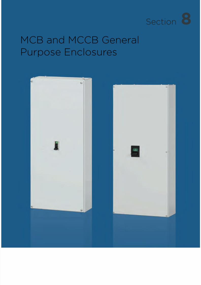
7/21/2019 TE Dorman Smith Product Portofolio 2011
http://slidepdf.com/reader/full/te-dorman-smith-product-portofolio-2011 131/182
8Section
MCB and MCCB General
Purpose Enclosures
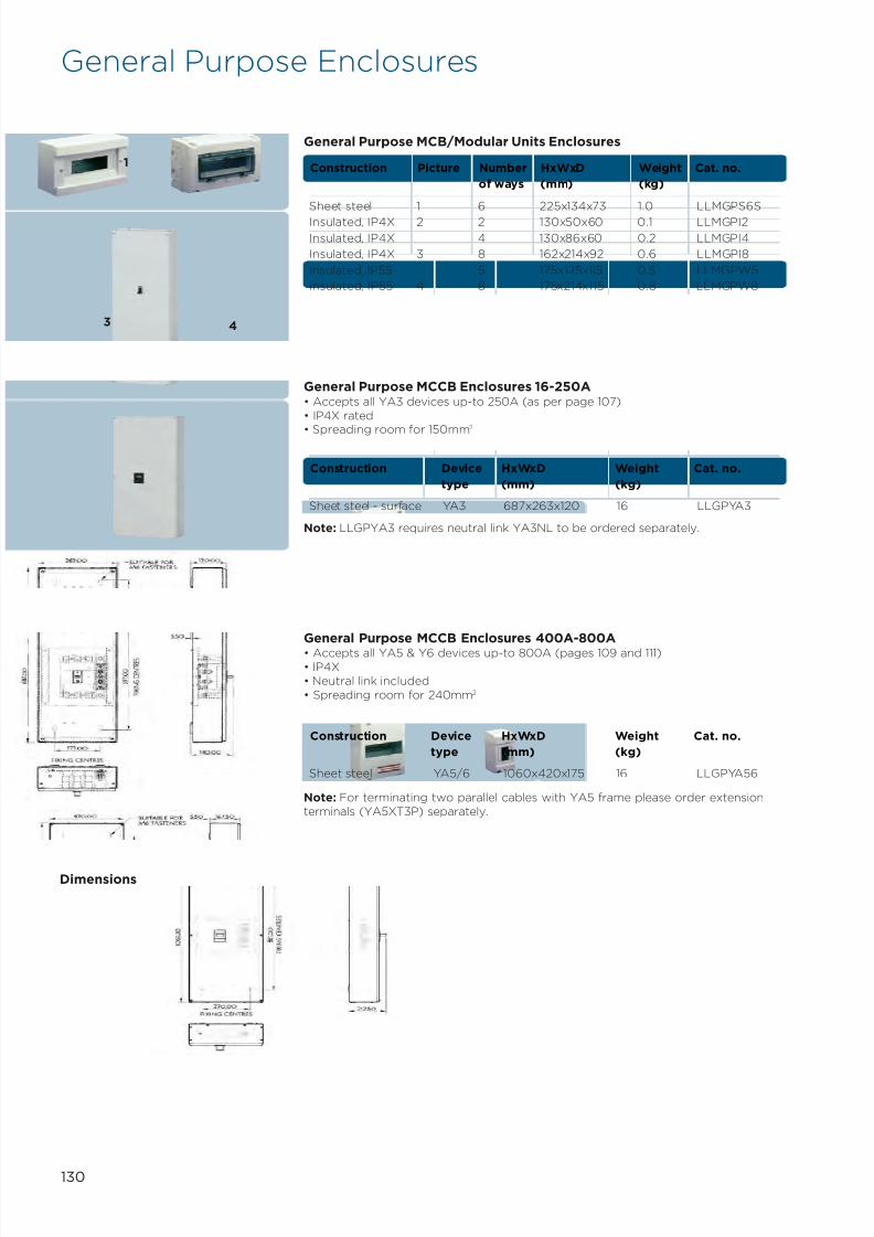
7/21/2019 TE Dorman Smith Product Portofolio 2011
http://slidepdf.com/reader/full/te-dorman-smith-product-portofolio-2011 132/182
General Purpose Enclosures
Sheet steel 1 6 225x134x73 1.0 LLMGPS6S
Insulated, IP4X 2 2 130x50x60 0.1 LLMGPI2
Insulated, IP4X 4 130x86x60 0.2 LLMGPI4
Insulated, IP4X 3 8 162x214x92 0.6 LLMGPI8
Insulated, IP55 5 175x125x115 0.5 LLMGPW5
Insulated, IP55 4 8 175x214x115 0.8 LLMGPW8
Construction Picture Number HxWxD Weight Cat. no.
of ways (mm) (kg)
General Purpose MCB/Modular Units Enclosures
Sheet steel - surface YA3 687x263x120 16 LLGPYA3
Construction Device HxWxD Weight Cat. no.
type (mm) (kg)
General Purpose MCCB Enclosures 16-250A• Accepts all YA3 devices up-to 250A (as per page 107)• IP4X rated
• Spreading room for 150mm2
Note: LLGPYA3 requires neutral link YA3NL to be ordered separately.
Note: For terminating two parallel cables with YA5 frame please order extensionterminals (YA5XT3P) separately.
Sheet steel YA5/6 1060x420x175 16 LLGPYA56
Construction Device HxWxD Weight Cat. no.
type (mm) (kg)
General Purpose MCCB Enclosures 400A-800A• Accepts all YA5 & Y6 devices up-to 800A (pages 109 and 111)• IP4X• Neutral link included• Spreading room for 240mm2
1 2
3 4
130
Dimensions

7/21/2019 TE Dorman Smith Product Portofolio 2011
http://slidepdf.com/reader/full/te-dorman-smith-product-portofolio-2011 133/182
9Section
Technical Data & Applications

7/21/2019 TE Dorman Smith Product Portofolio 2011
http://slidepdf.com/reader/full/te-dorman-smith-product-portofolio-2011 134/182
132
7/21/2019 TE Dorman Smith Product Portofolio 2011
http://slidepdf.com/reader/full/te-dorman-smith-product-portofolio-2011 135/182
133
Technical Data & Applications
Index
Compliance with International Standards 134
Standard Terminology 135
Current Carrying and Switching Devices 137
Miniature Circuit Breakers (MCBs) 140
Residual Current Circuit Breakers (RCCBs) 145
Modular Contactors 147
Moulded Case Circuit Breakers (MCCBs) 151
Motor Starting Applications (MCCBs) 152
Discrimination and Cascading 153
System Sizing and Diversity 160
Prospective Short-circuit Current 161
Earth Fault Protection including MCCB Max Zs 164
Forms of Separation 167
Ingress Protection 169
Loadline MCCB Insulation Data 170
Loadline YA2 Frame MCCB Characteristics 171
Loadline YA3 Frame MCCB Characteristics 172
Loadline YA5 and Y6 Frame MCCB Characteristics 173
Loadline Y7 and Y8 Frame MCCB Characteristics 174

7/21/2019 TE Dorman Smith Product Portofolio 2011
http://slidepdf.com/reader/full/te-dorman-smith-product-portofolio-2011 136/182
134
Compliance with InternationalStandards
Dorman Smith branded products comply with internationally recognised technicaland quality standards to ensure that each product is fully capable of meeting therelevant standard requirements for its intended use.
The design, manufacture, procurement, supply and servicing of Dorman Smith
branded products is also governed by compliance to an international standardthrough the operation of a Quality Management System.
• Quality Management System BS EN ISO 9001:2008
The Institute of Electrical Engineers (IEE) British Standard BS 7671 addressesRequirements for Electrical Installations and dictates that all relevant products mustcomply with applicable British, International or Harmonised Standards according tothe intended installation and application of the equipment. The BS 7671 documentis commonly referred to as ‘The Wiring Regulations’.
Products are type tested, manufactured, routinely tested and assembled inaccordance and compliance with a number of relevant Harmonised Standardsrecognised by the electrical industry.
A Harmonised Standard is a European Standard formally presented by theEuropean Committee for Electrotechnical Standardisation, CENELEC, to theEuropean Commission and published in its official journal. These documents aredenoted by the prefix EN (European Norm).
The products listed within this catalogue conform to appropriate electrical andmechanical standards as follows:
• MCB Distribution Boards EN 60439-3• Panel Boards EN 61439-2• MCBs EN 60898• MCCBs EN 60947-2• Switches EN 60947-3• RCCBs EN 61008• RCBOs EN 61009• Contactors EN 61095
In addition to the above, and where appropriate, Dorman Smith branded productsalso comply with the relevant requirements of the standard for protection againstphysical, mechanical and liquid ingress as follows:
• Ingress Protection EN 60529
7/21/2019 TE Dorman Smith Product Portofolio 2011
http://slidepdf.com/reader/full/te-dorman-smith-product-portofolio-2011 137/182
135
Standard Terminology
The Harmonised Standard EN 60898 and the IEE Wiring Regulations BS 7671:2008contain references to a set of adopted standard terminology for the principaldevice parameters with regard to MCBs. This terminology is also embraced byother standards with regard to MCCBs and switches (EN60947-2 and EN 60947-3).
The standard terminology relates to the following parameters:
Rated Operational Voltage, Ue
Rated Insulation Voltage, Ui
Rated Current, InRated Short Circuit Capacity, Icn
Rated Service Short Circuit Breaking Capacity, Ics
Rated Ultimate Breaking capacity, Icu
Rated Voltage and Current
Rated Operational Voltage, Ue
The nominal voltage of the system should not exceed the stated value of Ue.For example: single-pole Ue = 230/400V, three-pole Ue = 400V.
The standardised values of 230V and 230/400V will progressively replace 240V,220/380V and 240/415V.
Rated Insulation Voltage, Ui
This is the voltage upon which the dielectric properties are based, using tests athigh voltage and mains frequency.
Unless otherwise stated, the rated insulation voltage is the value of the maximumrated voltage of the circuit breaker.
In no case shall the maximum rated voltage exceed the rated insulation voltage.
Rated Current, InThis is the current that the circuit breaker will carry continuously under specifiedconditions and upon which the time/current characteristics are based.
Unless otherwise stated, this value is based upon a reference ambient temperatureof 30 degrees Celsius.
EN 60898 Standard refers to the following terms:
Short Circuit Capacity
Rated Short Circuit Capacity, Icn
The calculated prospective fault current at the incoming terminals of thecircuit breaker should not exceed the stated value. For example: Icn = 10kA(marked 10000).
Service Short Circuit Breaking Capacity, Ics
This value is the maximum level of fault current operation, after which furtherservice of the device is assured without loss of performance. Note that there is norequirement for Ics to be marked on the device.
There is a proscribed relationship between Ics and Icn, as follows:For values of Icn up to 6000A Ics = Icn
For values of Icn 6000A to 10000A Ics = 0.75Icn (but with a minimum value of Ics = 6000A)For values of Icn above 10000A Ics = 0.5Icn (but with a minimum value of Ics = 7500A)

7/21/2019 TE Dorman Smith Product Portofolio 2011
http://slidepdf.com/reader/full/te-dorman-smith-product-portofolio-2011 138/182
136
The EN 60947-2 and EN 60947-3 Standards also refer to the following terms.
Isolation SuitabilityThese define the requirements for the suitability of circuit breakers to performisolation duty by defining tests to which such units must comply. Conformingdevices must carry a standard symbol mark to show that they are suitable forisolation duty. For example, all Dorman Smith circuit breakers are so marked.
Utilisation CategoriesThe utilisation category of a circuit breaker is stated with reference to whetheror not it is specifically intended for discrimination by means of an intentional time
delay with respect to other circuit breakers in series on the load side undershort-circuit conditions.
Category AThis designates circuit breakers not specifically intended for selectivity with deviceson the load side. Circuit breakers will discriminate only up to certain fault levels,above which discrimination with devices on the load side cannot be guaranteed.
Category BThis designates circuit breakers specifically intended for selectivity with devices onthe load side. Such circuit breakers will incorporate some form of time delay.
EN 60947-2 recognises both a rated service and a rated ultimate short circuitbreaking capacity for both Category A and Category B circuit breakers.
Rated Service Breaking Capacity, Ics
In order to define this value, the circuit breakers under test must be subjected to atest sequence of:
Ics = o – t – co - t – co, where:o = opening time under fault conditionst = time interval before re-closing (not more than 3 minutes)c = closing operation on to a fault
After this test sequence, dielectric, terminal temperature and over-current tests areto be applied. The circuit breaker must meet certain test parameters to ensure thatthe device has not deteriorated in performance and can be put back into service.
Rated Ultimate Breaking capacity, Icu
In order to define this value, the circuit breakers under test must be subjected to a
test sequence of:
Icu = o – t– co.
After this test sequence, dielectric and over-current tests are to be applied.
The rated service breaking capacity (Ics) applies to short circuit faults that couldoccur in practice; whereas the ultimate short circuit capacity (Icu) is the maximumtheoretical fault value of the installation at the point of connection.
The standard defines the ratio between the two values. Ics will be shown as 25%,50%, 75% or 100% of its Icu value for Category A devices and 50%, 75% or 100% ofIcu for Category B devices.
A circuit breaker can remain in service after interrupting a short circuit up to its
rated value of Ics. However, where two or more faults occur between the Ics and Icuvalues, the capability of the device for continued operation must be verified.

7/21/2019 TE Dorman Smith Product Portofolio 2011
http://slidepdf.com/reader/full/te-dorman-smith-product-portofolio-2011 139/182
137
Current Carrying andSwitching Devices
SwitchA switch is a mechanical device capable of making, carrying and breaking currentunder normal circuit conditions.
Disconnector (Isolator)A disconnector is a mechanical switching device that provides the function ofcircuit isolation.
Switch DisconnectorThis device combines the functionality of the two foregoing devices; it providesmaking, carrying, breaking and isolation of current within a circuit.
FusesFuses can be combined with any of the above devices in any physical order. Theinclusion of a fuse will add the functionality of short circuit protection, breaking thecircuit when the current flow is higher than that for which the circuit is rated.
Combination DevicesIn order to enhance circuit protection, switches and fuses are often combined
within a single device. The physical composition of the device can be identified bythe literal position of the words in its description. For example, the word ‘fuse’ atthe beginning of the device description identifies the fuse as forming part of themoving contact system, whereas placing it at the end of the description identifiesthe fuse as a static link.
Functional Summary
Switch Current rating Isolation
Operational and insulation voltage Protection
Making and breaking of load
Short time current rating
Disconnector Current rating Protection
Isolation Making/breaking capability
Operational and insulation voltage
Short time current rating
Fuse Overload protection Switching
Short circuit protection
Term Features Features
provided not provided
Suitability for PurposeAll of these devices have the ability to carry rated current either continuously orfor a period of eight hours under defined conditions. Selection and specification ofa specific device depends upon the circuit application.

7/21/2019 TE Dorman Smith Product Portofolio 2011
http://slidepdf.com/reader/full/te-dorman-smith-product-portofolio-2011 140/182
138
Function
Fuse Combination Unit
Switching ApplicationsFor switching applications, the principal functions and capabilities include:
• Making and breaking operation
A switch must have the ability to make or break defined load and overloadcurrents at a rated operational voltage, for the useful life of the device.
• Short circuit action
The device must have the capability of handling short circuit current and/orthrough fault and/or fault making.
• Protection
The device must interrupt the circuit under overload and/or short circuitconditions.
• Isolation
To meet this requirement, the device must ensure disconnection of the supply forsafe downstream working. Facilities must be included for safety padlocking in the‘off’ position, together with positive indication of the contact position.
• Neutral switching
Where the neutral is reliably earthed, it is accepted that the neutral need not beswitched except in defined circumstances (e.g. the incoming switch disconnectorin a consumer unit) even though the Wiring Regulations (BS 7671:2008) class theneutral as a current carrying conductor.
In applications where the neutral cannot be confirmed as reliably earthed, the
neutral should be switched simultaneously with the phase(s) or alternativelyarranged to make before and break after the phase(s).
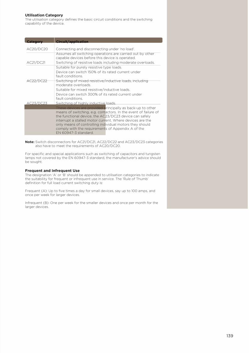
7/21/2019 TE Dorman Smith Product Portofolio 2011
http://slidepdf.com/reader/full/te-dorman-smith-product-portofolio-2011 141/182
139
Utilisation CategoryThe utilisation category defines the basic circuit conditions and the switchingcapability of the device.
AC20/DC20 Connecting and disconnecting under ‘no load’.
Assumes all switching operations are carried out by othercapable devices before this device is operated.
AC21/DC21 Switching of resistive loads including moderate overloads. Suitable for purely resistive type loads.
Device can switch 150% of its rated current underfault conditions.
AC22/DC22 Switching of mixed resistive/inductive loads, including moderate overloads.
Suitable for mixed resistive/inductive loads.
Device can switch 300% of its rated current underfault conditions.
AC23/DC23 Switching of highly inductive loads.
These devices are provided principally as back-up to othermeans of switching, e.g. contactors. In the event of failure ofthe functional device, the AC23/DC23 device can safelyinterrupt a stalled motor current. Where devices are the
only means of controlling individual motors they shouldcomply with the requirements of Appendix A of theEN 60947-3 standard.
Category Circuit/application
Note: Switch disconnectors for AC21/DC21, AC22/DC22 and AC23/DC23 categoriesalso have to meet the requirements of AC20/DC20.
For specific and special applications such as switching of capacitors and tungstenlamps not covered by the EN 60947-3 standard, the manufacturer’s advice shouldbe sought.
Frequent and Infrequent UseThe designation ‘A’ or ‘B’ should be appended to utilisation categories to indicatethe suitability for frequent or infrequent use in service. The ‘Rule of Thumb’definition for full load current switching duty is:
Frequent (A): Up to five times a day for small devices, say up to 100 amps, andonce per week for larger devices.
Infrequent (B): One per week for the smaller devices and once per month for thelarger devices.

7/21/2019 TE Dorman Smith Product Portofolio 2011
http://slidepdf.com/reader/full/te-dorman-smith-product-portofolio-2011 142/182
140
Miniature Circuit Breakers (MCBs)
In general terms, circuit breakers are thermal/magnetic electromechanical devicesthat provide current making, carrying and breaking functions and will ‘trip’ tointerrupt a circuit under abnormal conditions. MCBs are equipped with positivecontact indication flags: red indicates that the contact(s) are closed, greenindicates the open state. The contact(s) will open when tripped due to abnormalcircuit conditions or can be manually put into the open state by use of a handle.
These devices are used to provide protection and control of circuits againstoverload and short circuit conditions. Dorman Smith MCBs are supplied withvarious breaking capacities, particularly for ratings of 6kA and 10kA. The lowerrated devices are used typically in domestic installations, e.g. in consumer units,whereas the higher rated devices are suitable for a range of commercial andindustrial circuit protection applications.
The thermal and magnetic trip functions cater for different circuit abnormalities andoperate as follows:
Thermal Trip FunctionThe purpose of this form of protection is to interrupt the circuit upon sensing anoverload current. Typically, a bi-metallic strip is used such that it will deflect due todifferential expansion of the dissimilar metals in response to the heating effectcaused by the passage of current through it. The higher the current, the greater willbe the heating effect and the more the deflection. At a preset point the physicaldeflection will be sufficient to actuate the tripping mechanism, opening thecontact(s) and interrupting the circuit.
Magnetic Trip FunctionThe purpose of this form of tripping is to protect against the effects of short circuitfault currents. A wire coil or solenoid is used to provide this function, operating thetrip mechanism when the over-current reaches a preset magnitude. As the faultcurrent rapidly increases, the magnetic field also increases, energising the coil andmoving a cam that is part of the contact assembly to fully open the contact(s)thereby interrupting the circuit.
CharacteristicsMCBs are designed according to one of three distinct tripping characteristicsdesignated B, C or D. These designations relate to the magnetic trip setting and
indicate the multiple of nominal current that will be tolerated by the device beforetripping. The following table illustrates these characteristics with typical duties and
applications. The nominal rated current is denoted by the symbol In.
B 3-5 In Light duty, resistive loads
C 5-10 In Fluorescent lights, small motors, inductive loads
D 10-20 In Sodium lights, large motors (>3kW), largeinductive loads
Type Magnetic Application
trip
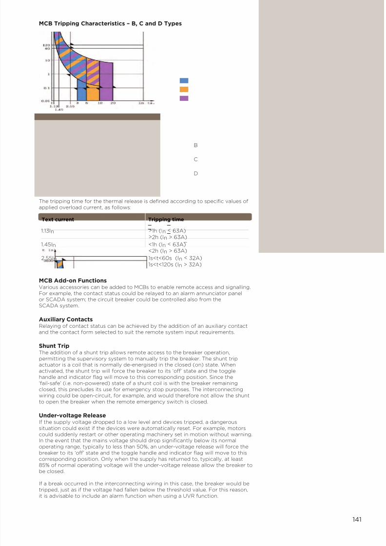
7/21/2019 TE Dorman Smith Product Portofolio 2011
http://slidepdf.com/reader/full/te-dorman-smith-product-portofolio-2011 143/182
141
MCB Tripping Characteristics – B, C and D Types
MCB Add-on Functions
Various accessories can be added to MCBs to enable remote access and signalling.For example, the contact status could be relayed to an alarm annunciator panelor SCADA system; the circuit breaker could be controlled also from theSCADA system.
Auxiliary ContactsRelaying of contact status can be achieved by the addition of an auxiliary contactand the contact form selected to suit the remote system input requirements.
Shunt TripThe addition of a shunt trip allows remote access to the breaker operation,permitting the supervisory system to manually trip the breaker. The shunt tripactuator is a coil that is normally de-energised in the closed (on) state. Whenactivated, the shunt trip will force the breaker to its ‘off’ state and the togglehandle and indicator flag will move to this corresponding position. Since the
‘fail-safe’ (i.e. non-powered) state of a shunt coil is with the breaker remainingclosed, this precludes its use for emergency stop purposes. The interconnectingwiring could be open-circuit, for example, and would therefore not allow the shuntto open the breaker when the remote emergency switch is closed.
Under-voltage ReleaseIf the supply voltage dropped to a low level and devices tripped, a dangeroussituation could exist if the devices were automatically reset. For example, motorscould suddenly restart or other operating machinery set in motion without warning.In the event that the mains voltage should drop significantly below its normaloperating range, typically to less than 50%, an under-voltage release will force thebreaker to its ‘off’ state and the toggle handle and indicator flag will move to thiscorresponding position. Only when the supply has returned to, typically, at least85% of normal operating voltage will the under-voltage release allow the breaker tobe closed.
If a break occurred in the interconnecting wiring in this case, the breaker would betripped, just as if the voltage had fallen below the threshold value. For this reason,it is advisable to include an alarm function when using a UVR function.
The tripping time for the thermal release is defined according to specific values ofapplied overload current, as follows:
1.13In >1h (In < 63A) >2h (In > 63A)
1.45In <1h (In < 63A) <2h (In > 63A)
2.55In 1s<t<60s (In < 32A) 1s<t<120s (In > 32A)
Text current Tripping time
B
C
D
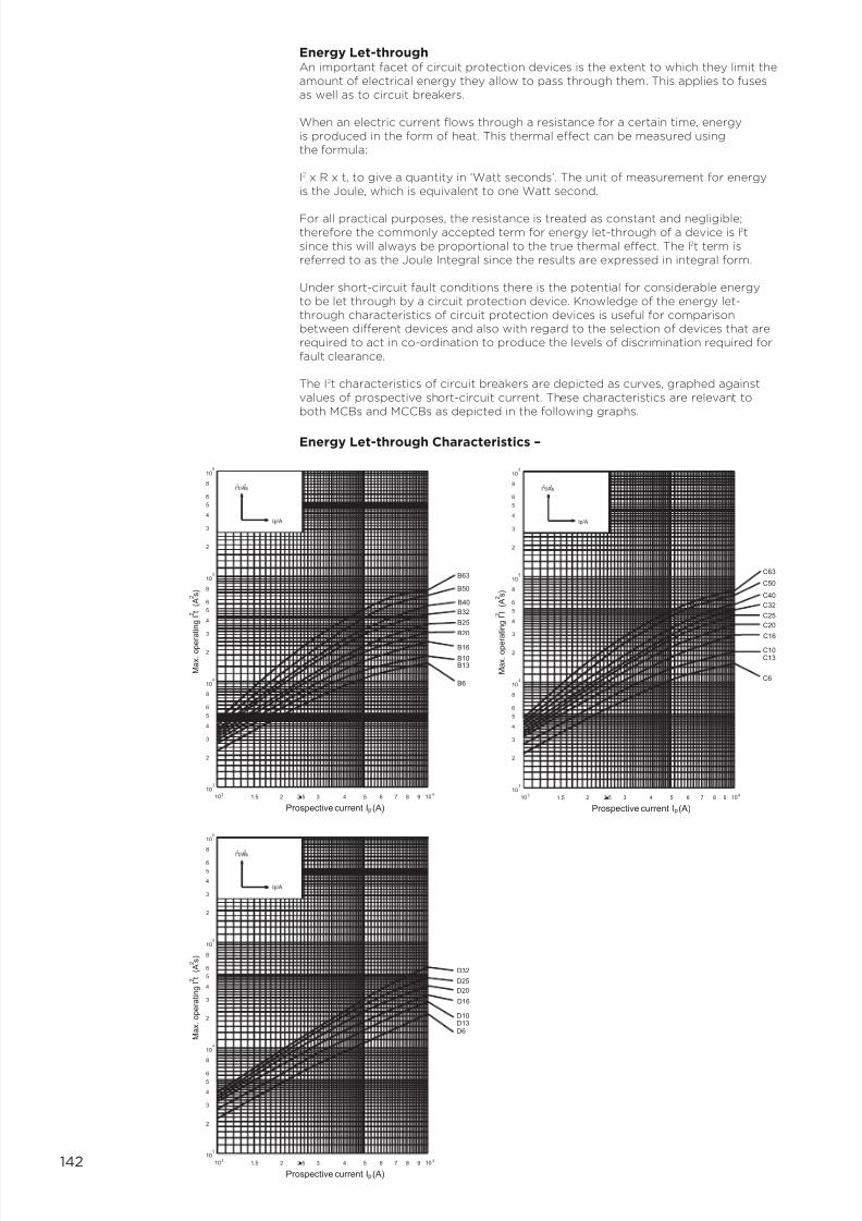
7/21/2019 TE Dorman Smith Product Portofolio 2011
http://slidepdf.com/reader/full/te-dorman-smith-product-portofolio-2011 144/182
142
Energy Let-throughAn important facet of circuit protection devices is the extent to which they limit theamount of electrical energy they allow to pass through them. This applies to fusesas well as to circuit breakers.
When an electric current flows through a resistance for a certain time, energyis produced in the form of heat. This thermal effect can be measured usingthe formula:
I2 x R x t, to give a quantity in ‘Watt seconds’. The unit of measurement for energyis the Joule, which is equivalent to one Watt second.
For all practical purposes, the resistance is treated as constant and negligible;therefore the commonly accepted term for energy let-through of a device is I2tsince this will always be proportional to the true thermal effect. The I 2t term isreferred to as the Joule Integral since the results are expressed in integral form.
Under short-circuit fault conditions there is the potential for considerable energyto be let through by a circuit protection device. Knowledge of the energy let-through characteristics of circuit protection devices is useful for comparisonbetween different devices and also with regard to the selection of devices that arerequired to act in co-ordination to produce the levels of discrimination required forfault clearance.
The I2t characteristics of circuit breakers are depicted as curves, graphed againstvalues of prospective short-circuit current. These characteristics are relevant toboth MCBs and MCCBs as depicted in the following graphs.
Energy Let-through Characteristics –
C6
C13
C16
C10
C20
C25
C32
C40
C50
C63
3
10
10 31.5 2 2.5 3 4 5 6 87 109
4
3
2
5
4
6
8
104
2
3
4
5
6
8
105
2I t/As
2
3
6
4
5
10
8
Ip/A
6
2
2 A ( t I g n i t a r e p o . x a M
s )
Prospective current I (A)p
2
D6D13
D16
D10
D20
D25
D32
B32
3
10
103
1.5 2 2.5 3 4 5 6 87 109 4
3
2
5
4
6
8
104
2
3
4
5
6
8
105
B13
B6
B16
B10
B20
B25
2I t/As
2
3
6
4
5
10
8
Ip/A
6
B40
B50
B63
2
2 A ( t I g n i t a r e p o . x a M
s )
Prospective current I (A)p
2
3
10
103
1.5 2 2.5 3 4 5 6 87 109 4
3
2
5
4
6
8
104
2
3
4
5
6
8
105
2I t/As
2
3
6
4
5
10
8
Ip/A
6
2
2 A ( t I g n i t a r e p o . x a M
s )
Prospective current I (A)p
2

7/21/2019 TE Dorman Smith Product Portofolio 2011
http://slidepdf.com/reader/full/te-dorman-smith-product-portofolio-2011 145/182
143
Within the EN 60898 standard, circuit breakers with ‘B’ and ‘C’ characteristics arecategorised into energy limiting classes 1, 2 and 3, with Class 3 denoting deviceshaving the lowest energy let-through. The appropriate energy class is markedwithin a square box on conforming devices. Dorman Smith MCBs are categorisedwithin Class 3.
The following table indicates the maximum energy let-through values permissible ineach class, stated in Watt-seconds. In practice, compliance with the standard ischecked on the circuit breakers with the highest applicable rated current within therange, normally 40A.
6kA 1-16 100,000 120,000 35,000 42,000
20-32 No 130,000 160,000 45,000 55,000
40 limits 156,000 192,000 54,000 66,000
10kA 1-16 specified 240,000 290,000 70,000 84,000
20-32 310,000 370,000 90,000 110,000
40 372,000 444,000 108,000 132,000
Rated Current Class 1 Class 2 Class 3short- rating (A) I2t max. I2t max. I2t max.
circuit B type and B type C type B type C type
capacity C type
70
60
50
40
30
20
10
0
-10
-20
-30
-40
0 .5 0 .6 0 .7 0 .8 0 .9 1 .0 1 .1 1 .2 1 . 3 1 .4 1 . 5
T/°C
Correction factor is valid for current with times over 30 s
I(x°C) - test current at x ambient temperature
I(30°C) - test current at 30°C ambient temperature
In
Ambient temperature T/ OC
[A] -40 -30 -20 -10 0 10 20 30 40 50 60 70
0,5 0,61 0,6 0,59 0,57 0,56 0,54 0,52 0,5 0,47 0,44 0,41 0,38
1 1,22 1,2 1,18 1,15 1,12 1,09 1,05 1 0,94 0,88 0,82 0,75
1,6 1,95 1,92 1,89 1,84 1,79 1,74 1,68 1,6 1,51 1,42 1,32 1,2
2 2,44 2,4 2,36 2,30 2,24 2,18 2,1 2 1,88 1,77 1,65 1,5
4 4,88 4,8 4,72 4,61 4,49 4,36 4,20 4 3,77 3,55 3,29 3
6 7,32 7,2 7,09 6,91 6,73 6,54 6,31 6 5,66 5,33 4,94 4,5
10 12,2 12 11,8 11,5 11,2 10,9 10,5 10 9,44 8,89 8,23 7,5
13 15,9 15,6 15,4 14,9 14,5 14,1 13,6 13 12,2 11,5 10,7 9,75
16 19,5 19,2 18,9 18,4 17,9 17,4 16,8 16 15,1 14,2 13,2 12
20 24,4 24 23,6 23 22,4 21,8 21 21 18,8 17,7 16,5 15
25 30,5 30 2,5 28,8 28 27,2 26,3 25 23,6 22,2 20,6 18,8
32 39 38,4 37,8 36,9 35,9 34,9 33,6 32 30,2 28,4 26,3 24
40 48,8 48 47,8 46,1 44,9 43,6 42 40 37,7 35,5 32,9 30
50 61 60 59,1 57,6 56,1 54,5 52,6 50 47,2 44,4 41,2 37,5
63 76,9 75,6 74,4 72,6 70,7 68,7 66,2 63 59,4 56 51,9 47,3
I(x°C)
I(30°C) k= -----------------
Effect of the ambient temperature on the tripping characteristic
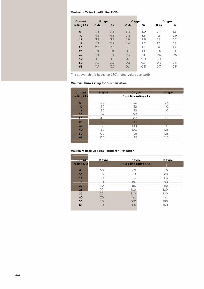
7/21/2019 TE Dorman Smith Product Portofolio 2011
http://slidepdf.com/reader/full/te-dorman-smith-product-portofolio-2011 146/182
144
Current B type C type D type
rating (A) 0.4s 5s 0.4s 5s 0.4s 5s
6 7.6 7.6 3.8 5.9 2.7 3.6
10 4.6 4.6 2.3 3.5 1.6 2.9
13 3.7 3.7 1.8 2.8 1.3 2.3
16 2.9 2.9 1.4 2.2 1.0 1.8
20 2.3 2.3 1.1 1.7 0.8 1.4
25 1.8 1.8 0.9 1.4 0.6 1.1 32 1.4 1.4 0.7 1.1 0.5 0.9
40 1.1 1.1 0.6 0.9 0.4 0.7
50 0.9 0.9 0.5 0.7 0.3 0.6
63 0.7 0.7 0.4 0.6 0.3 0.5
Maximum Zs for Loadlimiter MCBs
The above table is based on 230V rated voltage to earth.
Current B type C type D type
rating (A) Fuse link rating (A)
6 20 32 25
10 20 32 40
13 20 32 40
16 32 50 63
20 40 63 63
25 50 80 80
32 63 100 100
40 80 100 125
50 100 125 125
63 125 125 125
Minimum Fuse Rating for Discrimination
Current B type C type D type
rating (A) Fuse link rating (A)
6 63 40 40
10 80 63 63
13 80 63 63
16 80 80 80
20 80 80 80
25 100 100 100
32 100 100 100
40 125 125 125
50 160 160 160 63 160 160 160
Maximum Back-up Fuse Rating for Protection

7/21/2019 TE Dorman Smith Product Portofolio 2011
http://slidepdf.com/reader/full/te-dorman-smith-product-portofolio-2011 147/182
145
Currents of low magnitude caused by unintentional ‘leakage’ paths to earth can causedeterioration within circuit wiring and components with the potential to create arapidly escalating situation that will permit the current to reach dangerous levels.
Special forms of circuit breakers are designed to use the detection of earth leakageor ‘residual’ current to limit the effects of this type of fault.
The generic term ‘residual current device’ is used to describe a range of circuitprotection devices that include the functions of sensing and measurement of aleakage current, with subsequent tripping when the magnitude of the residualcurrent reaches a preset level. The purpose of these devices is to protect humanlife, livestock, property and equipment against the escalation of earth fault currentsto destructive magnitudes.
Two forms of technology are commonly employed in the design of residual currentdevices; electromagnetic and electronic. In both cases, a current transformer isused and is arranged such that normal current flows in the phase and neutralconductors cancel each other to produce a zero balance. The presence of anyresidual current will create an out-of-balance that can be used to signal theactuation of a mechanism for circuit interruption.
In the electromagnetic type, a trip relay is used as the actuation device. The relay ispowered by the fault current and therefore requires no external power source.
With electronic devices internal signal amplification allows a much smaller currenttransformer to be used, reducing the physical size of the circuit breaker. In thiscase, however, the actuation power is derived from both the fault current and themains power. Also, a separate earth reference connection may be required toensure continuity of operation in the event that the mains neutral is lost.
Residual current devices are accorded a ‘sensitivity’ coding that indicates the levelof residual current that would cause a trip action. Commonly, the availablesensitivity ranges are 10mA, 30mA, 100mA and 300mA. In general, the 10mA and30mA devices are used to protect human life, the 100mA and 300mA devicesbeing applied to protect wiring, cabling and equipment.
The degree of electrocution that could take place when a fault arises depends uponthe combined effects of the magnitude and duration of current flow. For sensitivity
levels of 30mA and below, tripping must be instantaneous to protect human life.Longer periods of residual current flow can be tolerated by equipment and the tripaction may not necessarily be required to interrupt the circuit instantaneously.
Residual Current Circuit BreakerThe RCCB device combines the functions of a switch with those of a residualcurrent device. It is often used in place of an incoming switch disconnector withthe advantage that it functions also as a residual current protection device. Thedisadvantage, however, is that a residual fault will cause the device to operateinterrupting ALL downstream circuits even when these circuits remain in ahealthy state.
Note that an RCCB should not be used as the sole means to provide completeprotection. It has no overload or short circuit protection and must therefore befurther protected by an upstream device having these capabilities. Frequently, theRCCB is used in consumer units and distribution boards to protect sub-circuits in asplit load configuration. In these applications, the upstream back-up is provided bythe Regional Electricity Company’s local fuse.
Residual Current Breaker with Overload ProtectionThe RCBO combines the functions of an MCB with those of a residual currentdevice. It will therefore provide protection against overload, short circuit andearth leakage.
Residual Current Circuit Breakers

7/21/2019 TE Dorman Smith Product Portofolio 2011
http://slidepdf.com/reader/full/te-dorman-smith-product-portofolio-2011 148/182
146
RCBOs and RCCBs – GeneralThese devices are furnished with a test pushbutton on the front face of themodule. Operation of this button will simulate the presence of a residual fault andthe test should be made frequently, say once per month, to assure continuedcorrect functionality of the device.
In addition to the range of sensitivities, RCBOs and RCCBs are available in twotypes, type AC and type A. These refer to the types of circuit for which thedevices are suitable.
Type AC: for use with residual sinusoidal ac, whether applied as a step or ramp.
Type A: for use with either residual sinusoidal ac or residual chopped (pulsating)dc, whether applied as a step or ramp.
A time delay facility may also be included, adjustable up to, typically, 50-70mS.This is denoted by ‘S’ included within the description and also marked on thedevice. This function is included in order to enable the device to be used aspart of a circuit device discrimination (or selectivity) arrangement. Without thetime delay, residual current circuit breakers cannot be easily used within adiscrimination scenario due to their inherent rapid tripping in response to residualcurrent detection.
Whereas RCBOs are single module width devices used in place of or alongsideMCBs in outgoing circuits, RCCBs are available in 2-pole and 4-pole forms and arereadily used in single phase and three phase distribution systems where they canfunction as either incoming or outgoing ways.
Due to their low levels of sensitivity RCCBs are generally equipped withsuppression filtering to avoid nuisance tripping that could be induced fromdisturbances in external or incoming circuits.

7/21/2019 TE Dorman Smith Product Portofolio 2011
http://slidepdf.com/reader/full/te-dorman-smith-product-portofolio-2011 149/182
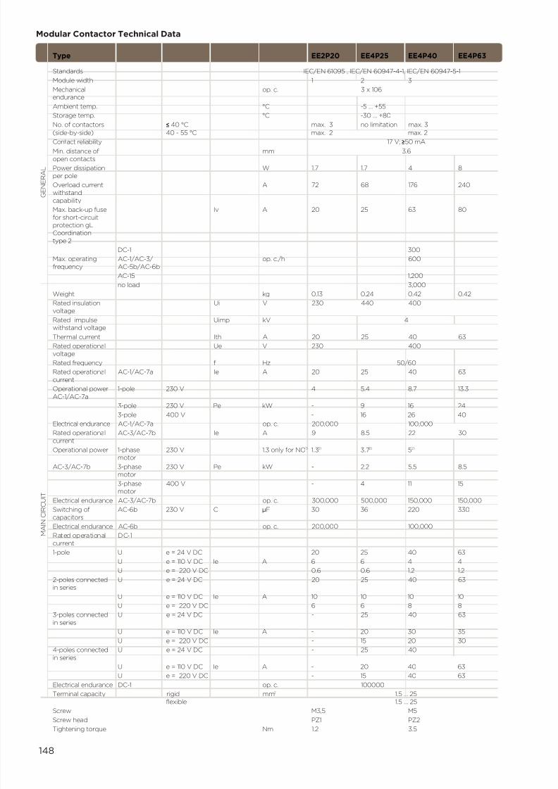
7/21/2019 TE Dorman Smith Product Portofolio 2011
http://slidepdf.com/reader/full/te-dorman-smith-product-portofolio-2011 150/182
148
Modular Contactor Technical Data
Type EE2P20 EE4P25 EE4P40 EE4P63
Standards IEC/EN 61095 , IEC/EN 60947-4-1, IEC/EN 60947-5-1
Module width 1 2 3
Mechanical op. c. 3 x 10⁶endurance
Ambient temp. °C -5 … +55
Storage temp. °C -30 … +80
No. of contactors ≤ 40 °C max. 3 no limitation max. 3
(side-by-side) 40 - 55 °C max. 2 max. 2
Contact reliability 17 V; ≥50 mA
Min. distance of mm 3.6
open contacts
Power dissipation W 1.7 1.7 4 8
per pole
Overload current A 72 68 176 240
withstand
capability
Max. back-up fuse Iv A 20 25 63 80
for short-circuitprotection gL
Coordination
type 2
DC-1 300
Max. operating AC-1/AC-3/ op. c./h 600
frequency AC-5b/AC-6b
AC-15 1,200no load 3,000
Weight kg 0.13 0.24 0.42 0.42
Rated insulation Ui V 230 440 400
voltage
Rated impulse Uimp kV 4withstand voltage
Thermal current Ith A 20 25 40 63
Rated operational Ue V 230 400
voltage
Rated frequency f Hz 50/60
Rated operational AC-1/AC-7a Ie A 20 25 40 63
current
Operational power 1-pole 230 V 4 5.4 8.7 13.3
AC-1/AC-7a
3-pole 230 V Pe kW - 9 16 24
3-pole 400 V - 16 26 40
Electrical endurance AC-1/AC-7a op. c. 200,000 100,000
Rated operational AC-3/AC-7b Ie A 9 8.5 22 30
current
Operational power 1-phase 230 V 1.3 only for NO1) 1.32) 3.72) 52)
motor
AC-3/AC-7b 3-phase 230 V Pe kW - 2,2 5.5 8.5motor
3-phase 400 V - 4 11 15motor
Electrical endurance AC-3/AC-7b op. c. 300,000 500,000 150,000 150,000
Switching of AC-6b 230 V C µF 30 36 220 330
capacitors
Electrical endurance AC-6b op. c. 200,000 100,000
Rated operational DC-1
current
1-pole U e = 24 V DC 20 25 40 63
U e = 110 V DC Ie A 6 6 4 4
U e = 220 V DC 0.6 0.6 1.2 1.2
2-poles connected U e = 24 V DC 20 25 40 63in series
U e = 110 V DC Ie A 10 10 10 10
U e = 220 V DC 6 6 8 8
3-poles connected U e = 24 V DC - 25 40 63
in series
U e = 110 V DC Ie A - 20 30 35
U e = 220 V DC - 15 20 30
4-poles connected U e = 24 V DC - 25 40
in series
U e = 110 V DC Ie A - 20 40 63
U e = 220 V DC - 15 40 63
Electrical endurance DC-1 op. c. 100000
Terminal capacity rigid mm2 1.5 … 25
flexible 1.5 … 25
Screw M3,5 M5
Screw head PZ1 PZ2
Tightening torque Nm 1.2 3.5
M A I N C I R C U I T
G E N E R A L

7/21/2019 TE Dorman Smith Product Portofolio 2011
http://slidepdf.com/reader/full/te-dorman-smith-product-portofolio-2011 151/182
149
Switching of Lamps
Max. number of lamps per pole at 230 V 50 Hz
Type Power (W) Current (A) C (µF) EE2P20 EE4P25 EE4P40 EE4P63
Incandescent lamps 60 0.26 – 33 33 65 85
(tungsten filament) 100 0.44 – 20 20 40 50
200 0.87 – 10 10 20 25
500 2.17 – 3 3 8 10
1000 4.35 – 1 1 4 5Incandescent lamps 18 0.37 2.7 22 24 90 140
uncompensated or series 24 0.35 2.5 22 24 90 140
compensated 36 0.43 3.4 17 20 65 95
58 0.67 5.3 14 17 45 70
Incandescent lamps 2 x 18 0.11 – 2 x 30 2 x 40 2 x 100 2 x 150
lead-lag circuit 2 x 24 0.14 – 2 x 24 2 x 31 2 x 78 2 x 118
2 x 36 0.22 – 2 x 17 2 x 24 2 x 65 2 x 95
2 x 58 0.35 – 2 x 10 2 x 14 2 x 40 2 x 60
Incandescent lamps 18 0.12 4.5 7 8 48 73
parallel compensated 24 0.15 4.5 7 8 48 73
36 000 4.5 7 8 48 73
58 0.32 7 4 5 31 47
Fluorescent lamps with 18 0.09 – 25 35 100 140
electronic ballast units (EVG) 36 0.16 – 15 20 52 75
58 0.25 – 14 19 50 722 x 18 0.17 – 2 x 12 2 x 17 2 x 50 2 x 70
2 x 36 0.32 – 2 x 7 2 x 10 2 x 26 2 x 38
2 x 58 0.49 – 2 x 7 2 x 9 2 x 25 2 x 36
High-pressure 50 0.61 – 14 18 38 55
mercury-vapour lamps. 80 001 – 10 13 29 42
Uncompensated 125 1.15 – 7 9 20 29
250 2.15 – 4 5 10 15
400 3.25 – 2 3 7 10
700 005 – 1 2 4 6
1000 008 – 1 1 3 4
High-pressure 50 0.28 7 4 5 31 47
mercury-vapour lamps. 80 0.41 8 4 5 27 41
Parallel compensated 125 0.65 10 3 4 22 33
250 1.22 18 1 2 12 18
400 1.95 25 1 1 9 13700 3.45 45 _ _ 5 7
1000 005 60 _ _ 4 5
Modular Contactor Technical Data continued
Type EE2P20 EE4P25 EE4P40 EE4P63
Rated operational Ue V 230 400
voltage
Rated insulation Ui V 230 440
voltage
Rated impulse Uimp kV 4
withstand voltage
Thermal current Ith A 20 25 40 63
AC-15 Rated 1-phase 230 V Ie A 6 6 6
operational current 1-phase 400 V - 4 4Electrical endurance AC-15 op. c. 300,000 500,000 150,000 150,000
Range of Uc % 85 … 110
control voltage
Control voltages Uc V 230
Surge immunity test kV 2
(1.2/50 µs), acc. to
IEC/EN 61000-4-5
Coil consumptionswitch-on
VA/W12/10 33/25 5/5 5/5
operation 2.8/1.2 5.5/1.6 5/5 5/5
Make/break delaysmake
ms15 _ 25 10 _ 30 15 _ 20 15 _ 20
break 10 _ 30 10 _ 30 35 _ 45 35 _ 45
Terminal capacityrigid
S1 … 2.5
flexible 1 … 2.5
Screw M3,5 M3
Screw head PZ1
Tightening torque Nm 0.6
C O N T R O L C I R C U I T
A U X I L I A R Y C O N T A C T S
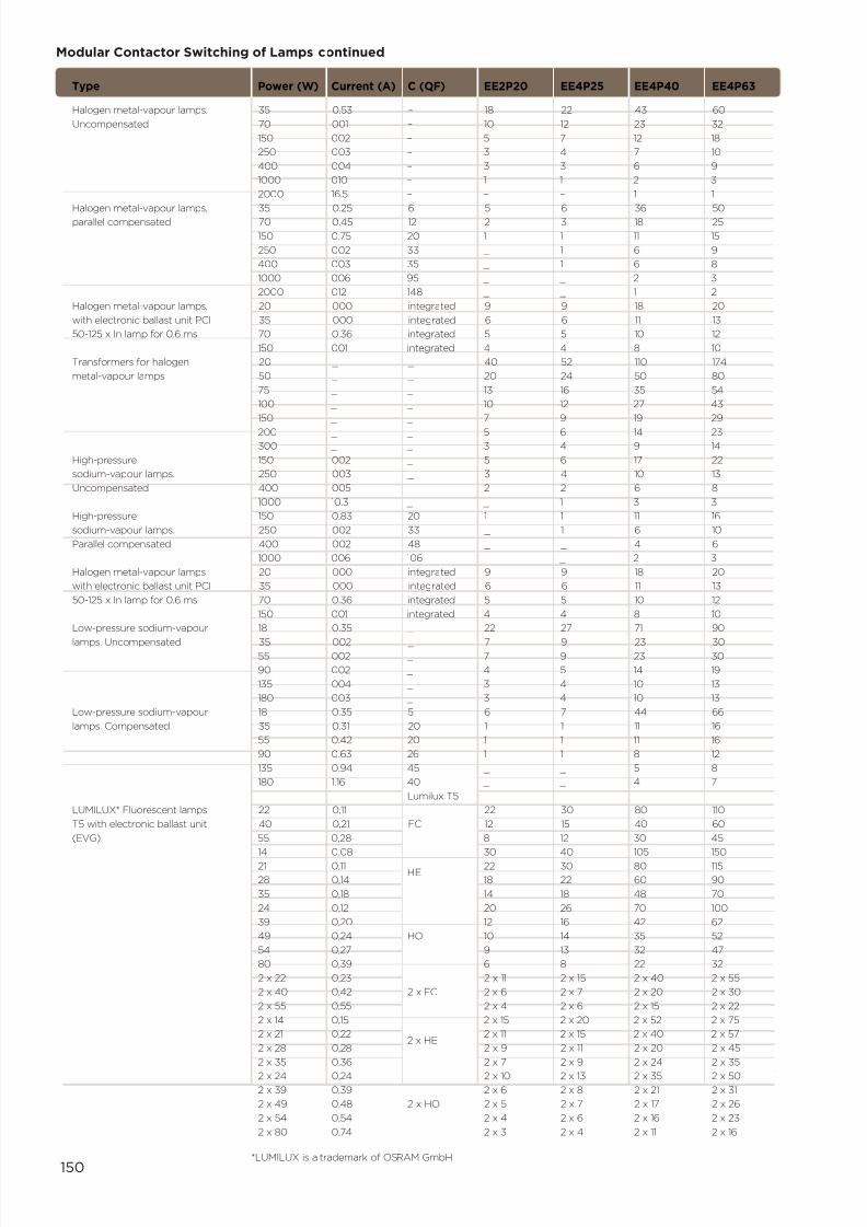
7/21/2019 TE Dorman Smith Product Portofolio 2011
http://slidepdf.com/reader/full/te-dorman-smith-product-portofolio-2011 152/182
150
Modular Contactor Switching of Lamps continued
Type Power (W) Current (A) C (µF) EE2P20 EE4P25 EE4P40 EE4P63
Halogen metal-vapour lamps. 35 0.53 – 18 22 43 60
Uncompensated 70 001 – 10 12 23 32
150 002 – 5 7 12 18
250 003 – 3 4 7 10
400 004 – 3 3 6 9
1000 010 – 1 1 2 3
2000 16.5 – – – 1 1
Halogen metal-vapour lamps, 35 0.25 6 5 6 36 50
parallel compensated 70 0.45 12 2 3 18 25
150 0.75 20 1 1 11 15
250 002 33 _ 1 6 9
400 003 35 _ 1 6 8
1000 006 95 _ _ 2 3
2000 012 148 _ _ 1 2
Halogen metal-vapour lamps, 20 000 integrated 9 9 18 20
with electronic ballast unit PCI 35 000 integrated 6 6 11 13
50-125 x In lamp for 0.6 ms 70 0.36 integrated 5 5 10 12
150 001 integrated 4 4 8 10
Transformers for halogen 20 _ _ 40 52 110 174
metal-vapour lamps 50 _ _ 20 24 50 80
75 _ _ 13 16 35 54
100 _ _ 10 12 27 43
150 _ _ 7 9 19 29
200 _ _ 5 6 14 23
300 _ _ 3 4 9 14
High-pressure 150 002 _ 5 6 17 22
sodium-vapour lamps. 250 003 _ 3 4 10 13
Uncompensated 400 005 _ 2 2 6 8
1000 10.3 _ _ 1 3 3
High-pressure 150 0.83 20 1 1 11 16
sodium-vapour lamps. 250 002 33 _ 1 6 10
Parallel compensated 400 002 48 _ _ 4 6
1000 006 106 _ _ 2 3
Halogen metal-vapour lamps 20 000 integrated 9 9 18 20
with electronic ballast unit PCI 35 000 integrated 6 6 11 13
50-125 x In lamp for 0.6 ms 70 0.36 integrated 5 5 10 12
150 001 integrated 4 4 8 10
Low-pressure sodium-vapour 18 0.35 _ 22 27 71 90
lamps. Uncompensated 35 002 _ 7 9 23 3055 002 _ 7 9 23 30
90 002 _ 4 5 14 19
135 004 _ 3 4 10 13
180 003 _ 3 4 10 13
Low-pressure sodium-vapour 18 0.35 5 6 7 44 66
lamps. Compensated 35 0.31 20 1 1 11 16
55 0.42 20 1 1 11 16
90 0.63 26 1 1 8 12
135 0.94 45 _ _ 5 8
180 1.16 40 _ _ 4 7
Lumilux T5
LUMILUX* Fluorescent lamps 22 0,11 22 30 80 110
T5 with electronic ballast unit 40 0,21 FC 12 15 40 60
(EVG) 55 0,28 8 12 30 45
14 0,08 30 40 105 15021 0,11
HE22 30 80 115
28 0,14 18 22 60 90
35 0,18 14 18 48 70
24 0,12 20 26 70 100
39 0,20 12 16 42 62
49 0,24 HO 10 14 35 52
54 0,27 9 13 32 47
80 0,39 6 8 22 32
2 x 22 0,23 2 x 11 2 x 15 2 x 40 2 x 55
2 x 40 0,42 2 x FC 2 x 6 2 x 7 2 x 20 2 x 30
2 x 55 0,55 2 x 4 2 x 6 2 x 15 2 x 22
2 x 14 0,15 2 x 15 2 x 20 2 x 52 2 x 75
2 x 21 0,222 x HE
2 x 11 2 x 15 2 x 40 2 x 57
2 x 28 0,28 2 x 9 2 x 11 2 x 20 2 x 45
2 x 35 0,36 2 x 7 2 x 9 2 x 24 2 x 35
2 x 24 0,24 2 x 10 2 x 13 2 x 35 2 x 50
2 x 39 0,39 2 x 6 2 x 8 2 x 21 2 x 31
2 x 49 0,48 2 x HO 2 x 5 2 x 7 2 x 17 2 x 26
2 x 54 0,54 2 x 4 2 x 6 2 x 16 2 x 23
2 x 80 0,74 2 x 3 2 x 4 2 x 11 2 x 16
*LUMILUX is a trademark of OSRAM GmbH
7/21/2019 TE Dorman Smith Product Portofolio 2011
http://slidepdf.com/reader/full/te-dorman-smith-product-portofolio-2011 153/182
151
The operation and application of the MCCB is similar to that of the MCB, howeverthis device has the air-break mechanism contained within a moulded case housingmade from a very robust non-conducting material. Generally, MCCBs exhibit muchhigher breaking capacities and rated current than their smaller counterparts andcan be used to perform full isolation duty. Consequently, MCCBs are employed inboth incoming and outgoing circuits. MCCBs are constructed to a particular framesize and typically provide rated current in the range 16-1600A.
These devices can be equipped with adjustable thermal and magnetic trippingmechanisms to cater for overload and short circuit protection to meet therequirements for isolation and Category A discrimination duty. Dorman Smithelectronic MCCBs provide adjustable long, short and instantaneous trip functions,allowing more complex overall tripping characteristics to be configured, allowingthese devices to be used for isolation and Category B discrimination requirements.(Refer to page 136 for Category definitions).
Devices equipped with the full range of adjustable trips for long, short andinstantaneous durations are generally referred to as ‘LSI-MCCBs’ to distinguishthem from the L and I only versions employed for Category A devices.
The range of accessories that can be added to MCCBs is similar to that given in thesection dealing with MCBs, including shunt trips, under-voltage releases and variousforms of auxiliary contacts. The physical size of triple-pole and four-pole MCCBs
allows these accessories to be internally mounted, although there are somerestrictions with regard to combinations of these that can be co-mounted. Forexample, either a shunt trip or under-voltage release can be incorporated, but notboth. Also, due to the much larger physical size of these devices compared withMCBs, additional safety features normally include interphase barriers and terminalshrouds to provide IP2X ingress protection at the terminals.
The tripping operation of some MCCBs is different from that of MCBs in that there arethree distinct positions of the toggle or handle. Whereas MCBs are either ‘on’ or ‘off’,MCCBs have a central position when they are tripped. As a further safety feature, thecoloured flags indicating the ‘on’ and ‘off’ states are masked in the tripped state. Thebreaker can be reset only after it has been set into the fully ‘off’ state.
MCCBs are equipped with a test pushbutton that allows periodic testing of themechanical tripping mechanism. As in the case of a fault trip, the device must be
moved into the ‘off’ position before it can be reset following a test.
These devices conform to EN 60947-2 therefore the definitions that apply to someparameters differ from those of EN 60898 that apply to miniature circuit breakers.These differences are explained in the section covering Standard Terminology.
Motor Control ApplicationsThe MCCB is a viable means of providing motor control switching. However,MCCBs used for this type of application are often required to provide only shortcircuit protection, with the overload protection catered for by a separate thermalor electronic overload relay. For this reason, specifically designed ‘motor control’MCCBs are available upon request, with only the single tripping mechanism.
The range of circuit breakers for each frame size includes a basic switchdisconnector version, generally in both triple-pole and four-pole variants. Devices ofthis type are sometimes referred to as ‘non-auto MCCBs’.
Moulded Case Circuit Breakers

7/21/2019 TE Dorman Smith Product Portofolio 2011
http://slidepdf.com/reader/full/te-dorman-smith-product-portofolio-2011 154/182
152
Loadline YA Frame MCCBs for Motor Starting (415 V ac)
P(Kw) Ie(A) Id"(A) In(A) Ii (lowertolerance) (A)
0.37 1.2 14 YA2/YA3 20 192
0.55 1.6 19 YA2/YA3 20 192
0.75 2 24 YA2/YA3 20 192
1.10 2.8 34 YA2/YA3 20 192
1.50 3.7 44 YA2/YA3 20 192
2.20 5.3 64 YA2/YA3 20 192
3.00 7 84 YA2/YA3 20 192
4.00 9 108 YA2/YA3 20 192
5.50 12 144 YA2/YA3 20 192
7.50 16 192 YA2/YA3 32 307
9.00 20 240 YA2/YA3 32 307
11.00 23 276 YA2/YA3 50 480
15.00 30 360 YA2/YA3 50 480
18.50 37 444 YA2/YA3 50 480
22.00 43 516 YA2/YA3 63 605
30.00 59 708 YA2/YA3 100 960
37.00 72 864 YA2/YA3 125 1200
45.00 85 1020 YA2/YA3 125 1200
55.00 105 1260 YA3 160 1664
75.00 140 1680 YA3 250 2600
90.00 170 2040 YA3 250 2600
110.00 210 2520 YA5 400 3840
132.00 224 2688 YA5 400 3840
150.00 255 3060 YA5 400 3840
Motor Motor full Sub-transient Breaker Breaker Breakerrating load starting frame rated instantaneous current current current trip threshold (set on max.)
Notes
1 In>le2 li/lower > ld"
The above table is suitable for DOL and Star Delta starting.

7/21/2019 TE Dorman Smith Product Portofolio 2011
http://slidepdf.com/reader/full/te-dorman-smith-product-portofolio-2011 155/182
153
In the context of power distribution schemes, the term ‘discrimination’ (sometimesreferred to as ‘selectivity’) describes a hierarchy of circuit devices that are arrangedsuch that a single upstream circuit breaker can fan out to several downstreamdevices to act in a co-ordinated fashion should a fault occur. Under fault conditions,only the upstream protective device closest to the fault should operate to clear thefault, leaving all other healthy circuits operable. This is especially important ininstallations where circuit failures could be life-threatening, such as in hospitals.
The concept of discrimination is similar to that of cascading, the prime differencebeing in the objectives of the application. Whereas discrimination is used to ensurecontinuity of supply to sub-circuits by limiting the disconnection to the faultedsub-circuit alone, cascading is used to buffer downstream protective devicesagainst the effects of high prospective short circuit currents.
In both cases, the protective devices are specifically selected to meet the criteriafor the type of co-ordination required.
When the selected devices are properly matched to fulfil the ideal discriminationprinciple described above, the co-ordinating devices are said to achieve ‘total’discrimination. In many practical installations, however, a partial discrimination maybe satisfactory for safe continuity of supply, with an added advantage of costsavings due to selecting a lower rated upstream circuit breaker.
Discrimination between two circuit breakers arranged in series may be based oneither current or time. Where the magnitude of the fault current is to be used asthe critical factor for selection, the co-ordination in this case is termed ‘currentdiscrimination’. Where the basis for selection is the duration over which theupstream device can withstand the fault current, the selection is to achieve ‘timediscrimination’. In some cases, time discrimination can be achieved by using anupstream device that has a built-in time delay.
Current Discrimination
In general, the basis for current discrimination is that the downstream protectivedevice will have a lower current rating than the upstream device. It should alsohave a lower instantaneous tripping point. The discrimination tables that followhighlight the consequential increase in discrimination level as the differential incurrent ratings between the devices increases.
Time DiscriminationDiscriminating by time between two devices in series relies on the operation of theupstream device being delayed at least until the downstream circuit breaker hastripped to clear the fault. The clearing time of the downstream device must be lessthan the time setting of the upstream device and the upstream device must also becapable of withstanding the fault current for the full duration of its time setting.There is generally no problem in achieving these conditions where the upstreamdevice is a Category B circuit breaker specifically designed for this type ofco-ordination duty.
Time/Current Characteristics
Comparison of the time/current characteristic graphs of the two devices proposedcan give a quick check on their suitability for co-ordination in both current and timediscrimination cases. Ideally, there should be no overlap of the respective curves toachieve total discrimination. If, however, the instantaneous portion of the curves do
intersect, a partial discrimination will be achieved at the current level projectedfrom the intersect point.
In the tables that follow, total discrimination is indicated by the letter ‘T’ inappropriate boxes. Total discrimination applies for all fault levels up to the lowerbreaking capacity of the two devices in co-ordination. Where a value is containedin any of the boxes, this indicates a partial discrimination of that value of currentlimit. If no discrimination is possible, this is shown by a dash symbol.
Discrimination
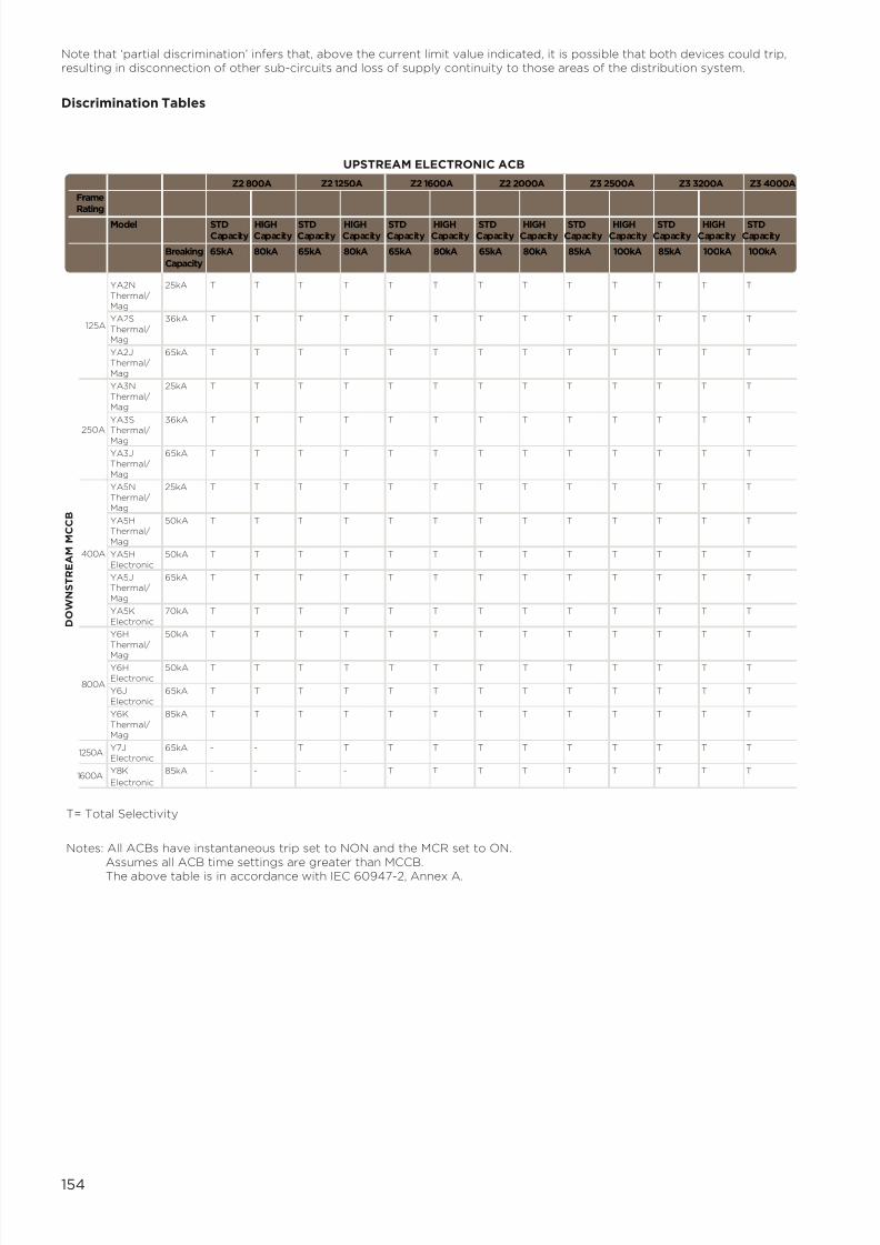
7/21/2019 TE Dorman Smith Product Portofolio 2011
http://slidepdf.com/reader/full/te-dorman-smith-product-portofolio-2011 156/182
154
Note that ‘partial discrimination’ infers that, above the current limit value indicated, it is possible that both devices could trip,resulting in disconnection of other sub-circuits and loss of supply continuity to those areas of the distribution system.
Discrimination Tables
FrameRating
Model STD HIGH STD HIGH STD HIGH STD HIGH STD HIGH STD HIGH STDCapacity Capacity Capacity Capacity Capacity Capacity Capacity Capacity Capacity Capacity Capacity Capacity Capacity
Breaking 65kA 80kA 65kA 80kA 65kA 80kA 65kA 80kA 85kA 100kA 85kA 100kA 100kA
Capacity
YA2N 25kA T T T T T T T T T T T T T
Thermal/Mag
YA2S 36kA T T T T T T T T T T T T T
Thermal/Mag
YA2J 65kA T T T T T T T T T T T T TThermal/
Mag
YA3N 25kA T T T T T T T T T T T T T
Thermal/Mag
YA3S 36kA T T T T T T T T T T T T T
Thermal/Mag
YA3J 65kA T T T T T T T T T T T T TThermal/
Mag
YA5N 25kA T T T T T T T T T T T T T
Thermal/Mag
YA5H 50kA T T T T T T T T T T T T TThermal/
Mag
YA5H 50kA T T T T T T T T T T T T T
Electronic
YA5J 65kA T T T T T T T T T T T T TThermal/
Mag
YA5K 70kA T T T T T T T T T T T T T
Electronic
Y6H 50kA T T T T T T T T T T T T T
Thermal/
Mag
Y6H 50kA T T T T T T T T T T T T TElectronic
Y6J 65kA T T T T T T T T T T T T T
Electronic
Y6K 85kA T T T T T T T T T T T T T
Thermal/Mag
Y7J 65kA - - T T T T T T T T T T TElectronic
Y8K 85kA - - - - T T T T T T T T T
Electronic
UPSTREAM ELECTRONIC ACB
Z2 800A Z2 1250A Z2 1600A Z2 2000A Z3 2500A Z3 3200A Z3 4000A
125A
250A
400A
800A
1250A
D O W N S T R E A M M C C B
1600A
T= Total Selectivity
Notes: All ACBs have instantaneous trip set to NON and the MCR set to ON.Assumes all ACB time settings are greater than MCCB.
The above table is in accordance with IEC 60947-2, Annex A.
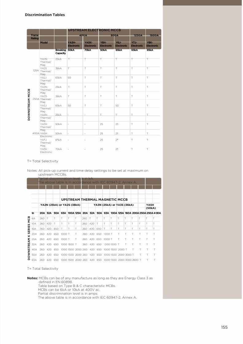
7/21/2019 TE Dorman Smith Product Portofolio 2011
http://slidepdf.com/reader/full/te-dorman-smith-product-portofolio-2011 157/182
155
FrameRating
Model YA5H- YA5K- Y6H- Y6J- Y7J- Y8K-Electronic Electronic Electronic Electronic Electronic Electronic
Breaking 50kA 70kA 50kA 65kA 65kA 85kACapacity
YA2N 25kA T T T T T TThermal/
Mag
YA2S 36kA T T T T T T
Thermal/Mag
YA2J 65kA 50 T T T T TThermal/
Mag
YA3N 25kA T T T T T TThermal/
Mag
YA3S 36kA T T T T T T
Thermal/Mag
YA3J 65kA 50 T T 50 T TThermal/
Mag
YA5N 25kA - - T T T T
Thermal/
Mag
YA5H 50kA - - 25 25 T T
Thermal/
Mag
YA5H 50kA - - 25 25 T TElectronic
YA5J 65kA - - 25 25 T TThermal/
Mag
YA5K 70kA - - 25 25 T T
Electronic
In 20A 32A 50A 63A 100A 125A 20A 32A 50A 63A 100A 125A 160A 200A250A250A400A
6A 260 T T T T T 260 T T T T T T T T T T
10A 260 420 T T T T 260 420 T T T T T T T T T
16A 260 420 650 T T T 260 420 650 T T T T T T T T
20A 260 420 650 1000 T T 260 420 650 1000 T T T T T T T
25A 260 420 650 1000 T T 260 420 650 1000 T T T T T T T
32A 260 420 650 1000 1500 T 260 420 650 1000 1500 T T T T T T
40A 260 420 650 1000 1500 2000 260 420 650 1000 1500 2000 T T T T T
50A 260 420 650 1000 1500 2000 260 420 650 1000 1500 2000 3000 T T T T
63A 260 420 650 1000 1500 2000 260 420 650 1000 1500 2000 3000 2600 T T T
UPSTREAM ELECTRONIC MCCB
UPSTREAM THERMAL MAGNETIC MCCB
400A 800A 1250A 1600A
125A
250A
400A
D
O W N S T R E A M M C C B
D O W N S T R E A M
K S E R I E S M C B
T= Total Selectivity
Notes: All pick-up current and time delay settings to be set at maximum onupstream MCCBs.
Partial discrimination level is in kA. The above table is in accordance with IEC 60947-2, Annex A.
T= Total Selectivity
Notes: MCBs can be of any manufacture as long as they are Energy Class 3 asdefined in EN 60898.
Table based on Type B & C characteristic MCBs. MCBs can be 6kA or 10kA at 400V ac. Partial discrimination level is in amps. The above table is in accordance with IEC 60947-2, Annex A.
YA2N (25kA) or YA2S (36kA) YA3N (25kA) or YA3S (36kA) YA5H(50kA)
Discrimination Tables

7/21/2019 TE Dorman Smith Product Portofolio 2011
http://slidepdf.com/reader/full/te-dorman-smith-product-portofolio-2011 158/182
156
UPSTREAM THERMAL MAGNETIC MCCB
T= Total Selectivity
Notes: Table based on Type D characteristic MCBs.
MCBs can be 6kA or 10kA at 400V ac.Partial discrimination level is in amps.
6A 166 192 307 480 605 832 960 1200 166 192 307 480 605 832 960 1200 1664 2080 2000 2400 3840
10A - - 307 480 605 832 960 1200 - - 307 480 605 832 960 1200 1664 2080 2000 2400 3840
16A - - - 480 605 832 960 1200 - - - 480 605 832 960 1200 1664 2080 2000 2400 3840
20A - - - 480 605 832 960 1200 - - - 480 605 832 960 1200 1664 2080 2000 2400 3840
25A - - - - 605 832 960 1200 - - - - 605 832 960 1200 1664 2080 2000 2400 3840
32A - - - - - 832 960 1200 - - - - - 832 960 1200 1664 2080 2000 2400 3840
40A - - - - - - 960 1200 - - - - - - 960 1200 1664 2080 2000 2400 3840
50A - - - - - - - 1200 - - - - - - - 1200 1664 2080 2000 2400 3840
63A - - - - - - - - - - - - - - - - 1664 2080 2000 2400 3840
D O W N S T R E A M
K S E R I E S D T Y P E M C B
YA2N (25kA) or YA2S (36kA) YA3N (25kA) or YA3S (36kA) YA5H (50kA)
In 16A 20A 32A 50A 63A 80A 100A 125A 16A 20A 32A 50A 63A 80A 100A 125A 160A 200A 250A 250A 400A
Discrimination Table

7/21/2019 TE Dorman Smith Product Portofolio 2011
http://slidepdf.com/reader/full/te-dorman-smith-product-portofolio-2011 159/182
157
Cascading is sometimes referred to as ‘back-up protection’. The technique ofcascading is used to allow circuit breakers with a breaking capacity lower than thevalue of prospective short-circuit current at the connection point to be used whenthese are positioned downstream of a current-limiting circuit breaker of higherbreaking capacity. The net result of this arrangement is that the downstreamdevice acquires an enhanced ’installed‘ breaking capacity, therefore a lessexpensive, lower breaking capacity breaker can be used.
The upstream circuit breaker must have the normally required breaking capacityfor its point of installation however, when combined with another circuit breakerdownstream, the two devices in series will be able to clear a larger fault. Forexample: if a 10A, 6kA MCB is place downstream of a YA frame MCCB rated at125A and 25kA, the MCB will have an installed breaking capacity of 14kA. Similarly,a 10A, 10kA MCB downstream of a YA frame MCCB rated at 250A and 25kA willhave an installed breaking capacity of 25kA.
It should be noted that the cascading technique is not limited to only two devicesin series. The important point is that it is the upstream device that is limiting thecurrent to a value that can be interrupted by the following device, so that thepattern of paired devices can be repeated many times in an hierarchy of devices.
The following tables give ‘installed breaking capacity’ values of downstream circuitbreakers for both the MCCB/MCB and MCCB/MCCB pairings of cascaded devices.
Note that all values shown are at 400V ac. The values for the installed breakingcapacities are given in kA.
Upstream YA frame MCCB with downstream S-series MCB –
Cascading
MCCB MCCB MCCB MCCB MCCB MCCB MCCB MCCB MCB YA2N YA2S YA2J YA3S YA3J YA3N YA3S YA3J (6kA) (25kA) (36kA) (65kA) (36kA) (65kA) (25kA) (36kA) (65kA) 125A 125A 125A 160A 160A 250A 250A 250A
6 14 14 14 12 12 12 12 12
10 14 14 14 12 12 12 12 12
16 14 14 14 12 12 12 12 12
20 14 14 14 12 12 12 12 12 32 14 14 14 12 12 12 12 12
40 12 12 12 10 10 10 10 10
50 12 12 12 10 10 10 10 10
63 12 12 12 10 10 10 10 10
Frame
Rating
Model YA2N T/Mag YA2S T/Mag YA2J T/Mag YA3N T/Mag YA3S T/Mag YA3J T/Mag
Current Breaking 25kA 36kA 65kA 25kA 36kA 65kARating Capacity
6A 10kA 25 30 30 25 25 25
10A 10kA 25 30 30 25 25 25
16A 10kA 25 30 30 25 25 25
20A 10kA 25 30 30 25 25 25
25A 10kA 25 30 30 25 25 25
32A 10kA 25 30 30 25 25 25
40A 10kA 25 30 30 23 23 23
50A 10kA 25 30 30 23 23 23
63A 10kA 25 30 30 23 23 23
UPSTREAM MCCB
125A 250A
D O W N S T R E A M M C B
Upstream YA frame MCCB with downstream K-series MCB –
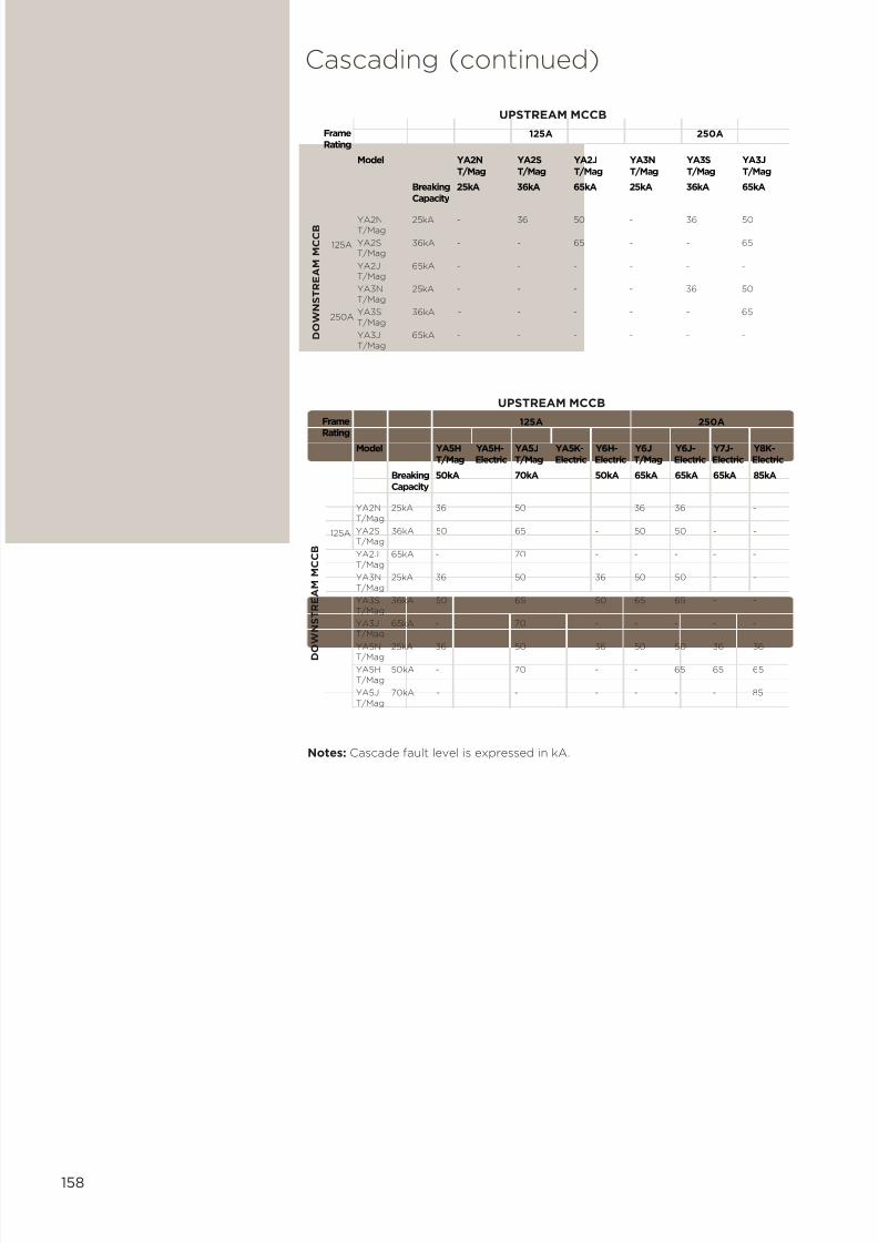
7/21/2019 TE Dorman Smith Product Portofolio 2011
http://slidepdf.com/reader/full/te-dorman-smith-product-portofolio-2011 160/182

7/21/2019 TE Dorman Smith Product Portofolio 2011
http://slidepdf.com/reader/full/te-dorman-smith-product-portofolio-2011 161/182
159
MCB, type B Fuse Current sizes rating (A) 20 25 35 50 63 80 100 125 160
6 0.5 0.8 1.7 3.1 7.0 10.0 10.0 10.0 10.0
10 0.4 0.7 1.4 2.3 3.4 4.8 7.5 10.0 10.0
13 0.7 1.4 2.3 3.4 4.8 7.5 10.0 10.0
16 1.3 2.0 2.9 4.2 6.0 9.5 10.0
20 1.9 2.7 3.8 5.6 8.5 10.0
25 1.8 2.6 3.6 5.4 8.0 10.0
32 2.4 3.2 4.2 6.8 10.0
40 3.2 4.2 6.8 9.5
50 3.8 5.7 8.5
63 3.8 5.7 8.5
Short-circuit Discrimination LevelsWhere a high prospective fault level exists at the MCB distribution point,discrimination at short-circuit levels should be considered. This will requirecomparison of the device I2t characteristics at the relevant prospective fault level.
Discrimination will be obtained at all fault levels for which the MCB total operatingI2t is lower than the pre-arcing I2t of the device closer to the supply.
The data for typical cartridge fuses can be extracted from graphs and is presentedin the following tables.
MCB, type C Current rating (A)
6 0.5 0.8 1.7 3.1 7.0 10.0 10.0 10.0 10.0
10 1.4 2.3 3.4 4.8 7.5 10.0 10.0
13 2.3 3.4 4.8 7.5 10.0 10.0
16 2.0 2.9 4.2 6.0 9.5 10.0
20 2.7 3.8 5.6 8.5 10.0
25 3.6 5.4 8.0 10.0
32 4.2 6.8 10.0
40 4.2 6.8 9.5
50 5.7 8.5
63 5.7 8.5
MCB, type D Current rating (A)
6 0.7 1.7 3.0 5.9 6.0 6.0 6.0 6.0 6.0
10 1.3 2.2 3.6 6.0 6.0 6.0 6.0
13 1.7 2.5 4.0 6.0 6.0 6.0
16 1.6 2.2 3.1 4.6 6.0 6.0
20 2.2 3.1 4.6 6.0 6.0
25 3.1 4.6 6.0 6.0
32 2.6 3.5 6.0 6.0
40 3.5 6.0 6.0
50 5.5 6.0
63
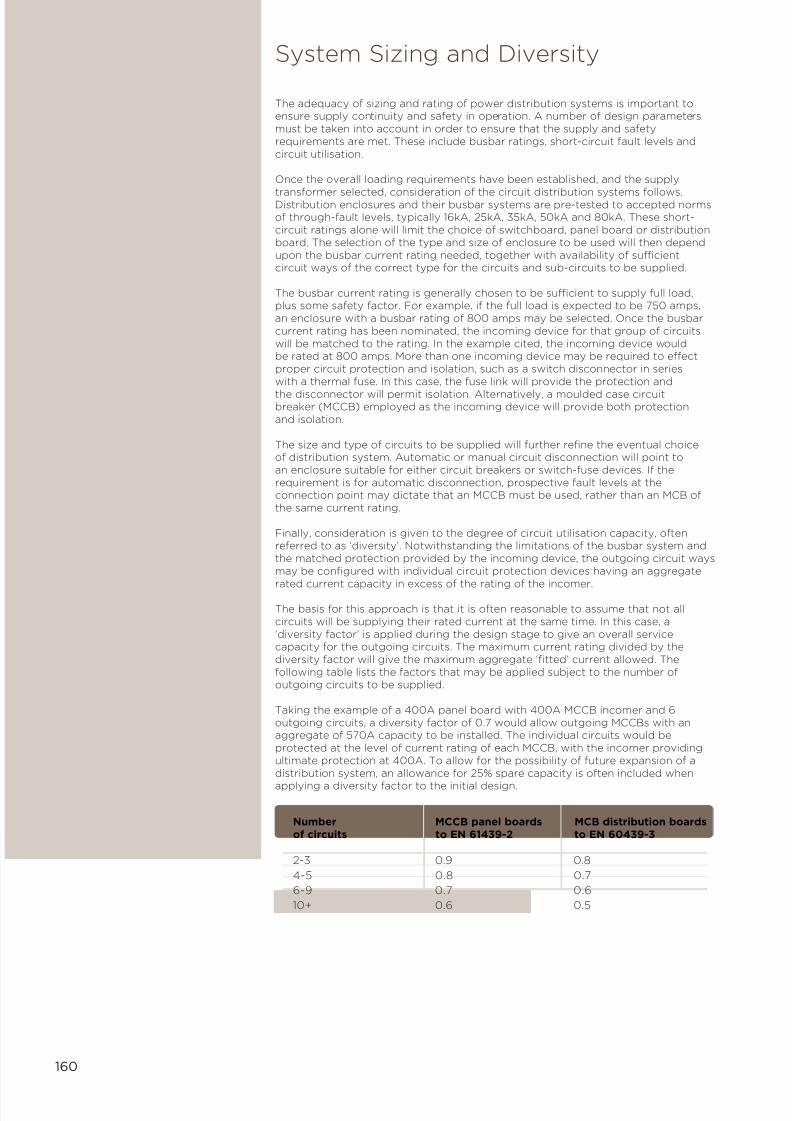
7/21/2019 TE Dorman Smith Product Portofolio 2011
http://slidepdf.com/reader/full/te-dorman-smith-product-portofolio-2011 162/182
160
Number MCCB panel boards MCB distribution boards of circuits to EN 61439-2 to EN 60439-3
2-3 0.9 0.8
4-5 0.8 0.7
6-9 0.7 0.6
10+ 0.6 0.5
The adequacy of sizing and rating of power distribution systems is important toensure supply continuity and safety in operation. A number of design parametersmust be taken into account in order to ensure that the supply and safetyrequirements are met. These include busbar ratings, short-circuit fault levels andcircuit utilisation.
Once the overall loading requirements have been established, and the supply
transformer selected, consideration of the circuit distribution systems follows.Distribution enclosures and their busbar systems are pre-tested to accepted normsof through-fault levels, typically 16kA, 25kA, 35kA, 50kA and 80kA. These short-circuit ratings alone will limit the choice of switchboard, panel board or distributionboard. The selection of the type and size of enclosure to be used will then dependupon the busbar current rating needed, together with availability of sufficientcircuit ways of the correct type for the circuits and sub-circuits to be supplied.
The busbar current rating is generally chosen to be sufficient to supply full load,plus some safety factor. For example, if the full load is expected to be 750 amps,an enclosure with a busbar rating of 800 amps may be selected. Once the busbarcurrent rating has been nominated, the incoming device for that group of circuitswill be matched to the rating. In the example cited, the incoming device wouldbe rated at 800 amps. More than one incoming device may be required to effectproper circuit protection and isolation, such as a switch disconnector in serieswith a thermal fuse. In this case, the fuse link will provide the protection and
the disconnector will permit isolation. Alternatively, a moulded case circuitbreaker (MCCB) employed as the incoming device will provide both protectionand isolation.
The size and type of circuits to be supplied will further refine the eventual choiceof distribution system. Automatic or manual circuit disconnection will point toan enclosure suitable for either circuit breakers or switch-fuse devices. If therequirement is for automatic disconnection, prospective fault levels at theconnection point may dictate that an MCCB must be used, rather than an MCB ofthe same current rating.
Finally, consideration is given to the degree of circuit utilisation capacity, oftenreferred to as ‘diversity’. Notwithstanding the limitations of the busbar system andthe matched protection provided by the incoming device, the outgoing circuit waysmay be configured with individual circuit protection devices having an aggregate
rated current capacity in excess of the rating of the incomer.
The basis for this approach is that it is often reasonable to assume that not allcircuits will be supplying their rated current at the same time. In this case, a‘diversity factor’ is applied during the design stage to give an overall servicecapacity for the outgoing circuits. The maximum current rating divided by thediversity factor will give the maximum aggregate ‘fitted’ current allowed. Thefollowing table lists the factors that may be applied subject to the number ofoutgoing circuits to be supplied.
Taking the example of a 400A panel board with 400A MCCB incomer and 6outgoing circuits, a diversity factor of 0.7 would allow outgoing MCCBs with anaggregate of 570A capacity to be installed. The individual circuits would beprotected at the level of current rating of each MCCB, with the incomer providingultimate protection at 400A. To allow for the possibility of future expansion of adistribution system, an allowance for 25% spare capacity is often included when
applying a diversity factor to the initial design.
System Sizing and Diversity

7/21/2019 TE Dorman Smith Product Portofolio 2011
http://slidepdf.com/reader/full/te-dorman-smith-product-portofolio-2011 163/182
161
The Prospective Short-circuit Current, or PSC, is the theoretical maximum faultcurrent that could exist at any point within a complete circuit distribution system.
The magnitude of the fault current at any particular point is calculated on the basis ofa ‘bolted’ (virtually permanent) fault path at that point and therefore assumes aconstant voltage, continuous current supply feeding the fault. Using this assumption,the PSC that could possibly exist at the bolted fault path would be limited only by the
sum of the circuit impedances of the complete current path, from high voltage feedto the supply transformer through to the bolted connection point. Since thisassumption cannot be fulfilled in practice (for example, the voltage will not remainconstant) the value of calculated PSC can never be exceeded in a practical scheme.
The foregoing commentary is particularly relevant to larger commercial and industrialnetworks, where many sub-systems are present and often, many sub-circuits withinthese. For more compact arrangements, such as domestic installations, where thedistribution scheme is contained within one or more consumer units, the situation ismuch simpler. The Regional Electricity Companies generally agree on a fixed faultlevel of 16kA at the local zone supply distribution point to one or more dwellings.Those dwellings that lie some distance from the zone origin point of the distributedsupply will have reduced PSC due to the higher impedance of the longer run ofservice cable. Consumer units should therefore have a minimum short-circuit rating of16kA. When an MCB trips, the combination of forced contact separation and rapid arcextinction produces a limiting effect on the fault current such that it will be
adequately handled within the normal 6kA breaking capacity of MCBs fitted todomestic installations.
PSC at the origin point –
In practice and with consideration of the total distribution network; the breakingcapacity of an individual circuit device would normally be less than that calculated forthe origin point of the scheme.
PSC at the connection point –
The breaking capacity of individual devices must be greater than (or at least equal to)the PSC at the specific point of their connection within a scheme. Conversely, wherethe circuit device breaking capacity is greater than the PSC at origin, there is no needfor further measurement or calculation in this regard.
The PSC at any particular connection point can be estimated, calculated, or
determined by measurement of the circuit impedance at that point. Measurement ofthe circuit impedances at all relevant connection points can be a laborious exercise;the calculation method is generally used since this can be readily carried out usingone of a number of available computer software packages.
PSC by calculation –The magnitude of the short-circuit current (rms value of the ac component) at theconnection point will depend upon:
• the PSC at the origin point.
• the total resistance in the circuit between the origin point and the relevant circuitreference point.
• whether the short-circuit condition is considered as phase-phase, phase-neutral orphase-earth.
The maximum PSC at the origin can be calculated from the following formula:
Supply transformer rating (kVA) x 100
√3 x secondary voltage x % transformer reactance
PSC by estimation –
To estimate the PSC, first calculate the total resistance in the LV circuit bydetermining the sizes and lengths of cables between the supply source and the pointunder consideration. Next, use the following table to find the cable resistances andsummate these to obtain the total resistance. Finally, use this value to read off theestimated PSC from the following graph.
Prospective Short-circuit Current
PSC (kA) =

7/21/2019 TE Dorman Smith Product Portofolio 2011
http://slidepdf.com/reader/full/te-dorman-smith-product-portofolio-2011 164/182
162
Nominal Cable length (m)
crosssectionalarea (mm2) 5 10 15 20 30 40 50 60 70 80 90 100
1 90.50 181.00
1.5 60.50 121.00 182.00
2.5 37.10 74.10 111.00 148.00
4 23.10 46.10 69.20 92.20 138.00 6 15.40 30.80 46.20 61.60 92.40 123.00
10 9.15 18.30 27.50 36.60 54.90 73.20 91.50 110.00
16 5.75 11.50 17.30 23.00 34.50 46.00 57.20 69.00 80.50 92.00
25 3.64 7.27 10.90 14.50 21.80 29.10 36.40 43.60 50.90 58.20 65.40 72.70
35 2.62 5.24 7.86 10.48 15.70 21.00 26.20 31.40 36.70 41.90 47.20 52.40
50 1.94 3.87 5.81 7.74 11.60 15.50 19.40 23.20 27.10 31.00 34.80 38.70
70 1.34 2.68 4.02 5.36 8.04 10.70 13.40 16.10 18.80 21.40 24.10 26.80
95 0.96 1.93 2.88 3.86 5.79 7.72 9.65 11.60 13.50 15.40 17.40 19.30
120 0.77 1.53 2.30 3.06 4.59 6.12 7.65 9.18 10.70 12.20 13.80 15.30
150 0.62 1.24 1.86 2.48 3.72 4.96 6.20 7.44 8.68 9.92 11.20 12.40
185 0.49 1.00 1.49 1.98 2.97 3.96 4.96 5.96 6.94 7.93 8.92 9.91
240 0.38 0.75 1.13 1.51 2.26 3.02 3.77 4.52 5.28 6.03 6.79 7.54
300 0.30 0.60 0.90 1.20 1.80 2.40 3.00 3.60 4.20 4.80 5.40 6.00
400 0.23 0.47 0.70 0.94 1.41 1.88 2.35 2.85 3.29 3.76 4.23 4.70
500 0.18 0.37 0.55 0.73 1.10 1.46 1.83 2.20 2.56 2.93 3.29 3.66
630 0.14 0.28 0.42 0.57 0.85 1.13 1.42 1.78 2.15 2.51 2.88 3.25
Maximum Resistance of Copper Conductors at 20°C (milli ohms)
Total Circuit Resistance (mΩ)
F a u l t C u r r e n t ( k A )
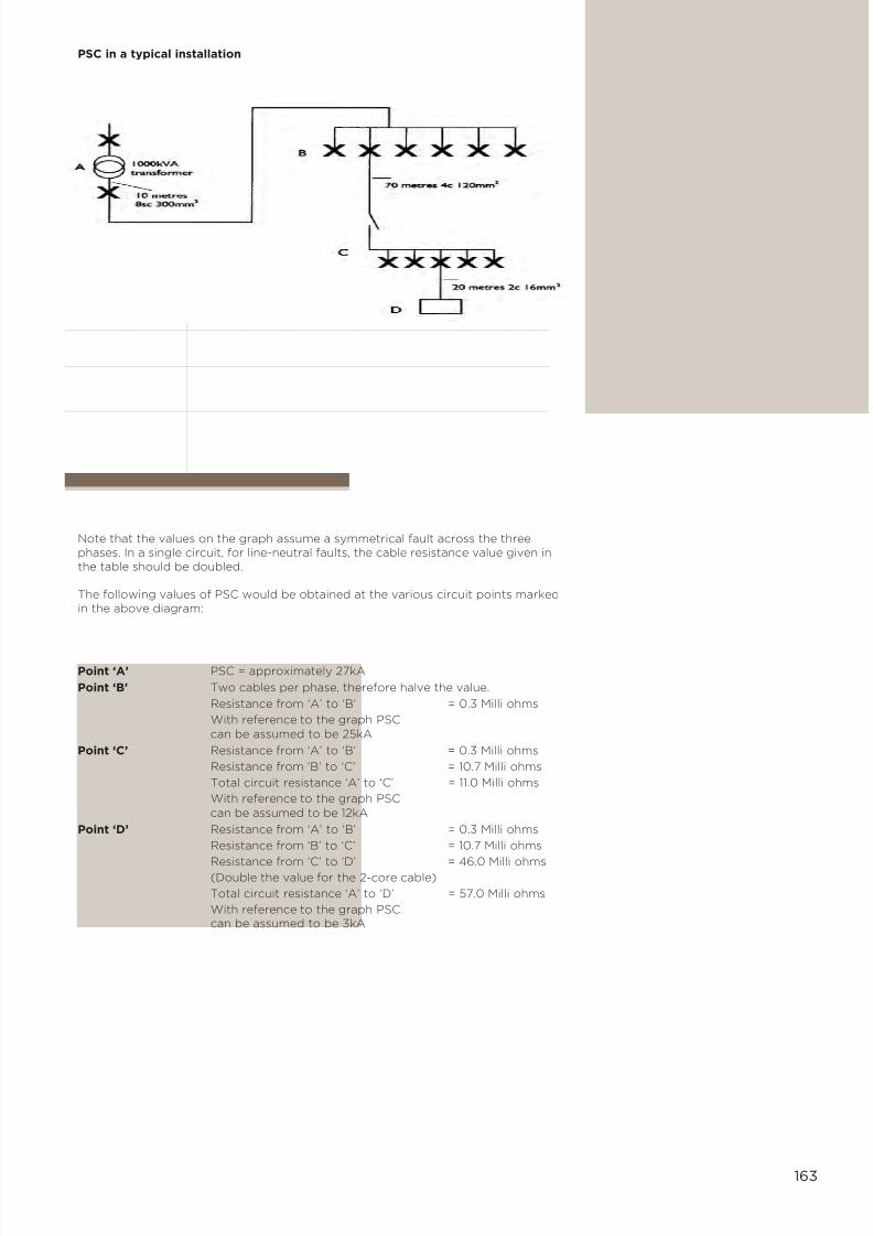
7/21/2019 TE Dorman Smith Product Portofolio 2011
http://slidepdf.com/reader/full/te-dorman-smith-product-portofolio-2011 165/182
163
PSC in a typical installation
Note that the values on the graph assume a symmetrical fault across the threephases. In a single circuit, for line-neutral faults, the cable resistance value given inthe table should be doubled.
The following values of PSC would be obtained at the various circuit points markedin the above diagram:
Point ‘A’ PSC = approximately 27kA
Point ‘B’ Two cables per phase, therefore halve the value.
Resistance from ‘A’ to ‘B’ = 0.3 Milli ohms
With reference to the graph PSC
can be assumed to be 25kA
Point ‘C’ Resistance from ‘A’ to ‘B’ = 0.3 Milli ohms
Resistance from ‘B’ to ‘C’ = 10.7 Milli ohms
Total circuit resistance ‘A’ to ‘C’ = 11.0 Milli ohms
With reference to the graph PSC
can be assumed to be 12kA
Point ‘D’ Resistance from ‘A’ to ‘B’ = 0.3 Milli ohms
Resistance from ‘B’ to ‘C’ = 10.7 Milli ohms
Resistance from ‘C’ to ‘D’ = 46.0 Milli ohms (Double the value for the 2-core cable)
Total circuit resistance ‘A’ to ‘D’ = 57.0 Milli ohms
With reference to the graph PSCcan be assumed to be 3kA

7/21/2019 TE Dorman Smith Product Portofolio 2011
http://slidepdf.com/reader/full/te-dorman-smith-product-portofolio-2011 166/182
164
One of the most common means of protecting persons against the effects of highvoltages and currents is by insulating the wiring and components. Most earth faults occurwhen some part of the insulation has broken down, creating the possibility of causingelectric shock through indirect contact with the faulty circuit. The breakdown of insulationcan often cause all or part of an enclosure or frame to become ‘live’ by raising conductiveparts to a hazardous voltage level. Touching any of the exposed parts of the enclosure orframe would then be highly dangerous and would most likely cause an electric shock.
Whilst protective devices may open quickly to minimise the possibility of high currentsflowing for any significant length of time, additional measures are necessary to limit thepotential earth fault current at source. In some cases fault current limiting resistors orinductors may be installed at the transformer star point however, in all cases, it isimportant to ensure that the impedance of circuit conductors is kept to a minimum sothat the voltage developed under fault conditions will be restricted. The earth fault loopimpedance is denoted Zs and is an important circuit design parameter.
Circuit designs must always ensure that the magnitude of the fault current will besufficient to trip the over-current protective devices within acceptable times as stated inthe IEE Wiring Regulations. Circuit breakers are designed to trip and therefore disconnectfaulted circuits very quickly. The design value of tripping time is generally expressed in theform of a graph that maps current against time and any practical scheme can be checkedagainst this value to ascertain conformance with the requirements.
The fault current can be established very simply using Ohm’s law, as follows:
Fault current = Phase-to-earth voltage
Zs
Once this value is known, the corresponding tripping time can be read from the relevantdevice’s time/current characteristic graph and the result compared with that given withinthe Wiring Regulations. In general, the higher the nominal voltage of an installation, theshorter will be the required disconnection time. For fixed equipment installations, themaximum disconnection time is stated as 5 seconds, whereas it is 0.4 seconds forportable equipment. The Regulations define ‘portable’ as including fixed outlet socketsthat may be used to supply apparatus that is movable or portable when in use.
The following table illustrates the maximum Zs allowable for MCBs to achieve thespecified disconnection times.
Since the complete loop impedance is the sum of the individual impedances of thesupply transformer winding, circuit phase conductor and protective circuitconductor, the total may be higher than that specified for in-time disconnection forthe protection device proposed. In these cases, several solutions may be possibleto overcome or at least assist in achieving compliance.
• The supply cable may be replaced by one with greater cross sectional area
• The short-circuit tripping threshold of the device may be set to a lower value(if it is adjustable)
• A Residual Current Device could be used to replace the circuit breaker in question
The following tables indicate the maximum Zs for Dorman Smith’s range ofMCCBs. Using these tables obviates the need to determine the suitability of adevice by reference to its time/current characteristic graph.
Earth Fault Protection
Current 6 10 16 20 25 32 40 50 63rating (A)
Type Bmax. Zs 8.00 4.80 3.00 2.40 1.92 1.50 1.20 0.96 0.76(ohms)
Type Cmax. Zs 4.00 2.40 1.50 1.20 0.96 0.75 0.60 0.48 0.38(ohms)
Type D
max. Zs 2.00 1.20 0.75 0.60 0.48 0.38 0.30 0.24 0.19(ohms)
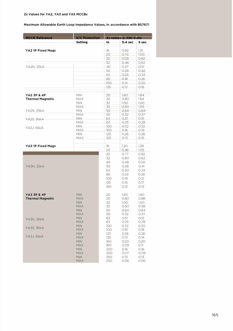
7/21/2019 TE Dorman Smith Product Portofolio 2011
http://slidepdf.com/reader/full/te-dorman-smith-product-portofolio-2011 167/182
165
Zs Values for YA2, YA3 and YA5 MCCBs
Maximum Allowable Earth Loop Impedance Values, in accordance with BS7671
MCCB Reference S/C Protection Zs values @ 230 Volts
Setting In 0.4 sec 5 sec
YA2 1P Fixed Mags 16 0.92 1.31
20 0.74 1.00
25 0.59 0.8232 0.46 0.62
YA2N, 25kA 40 0.37 0.51
50 0.29 0.42
63 0.23 0.33
80 0.18 0.26
100 0.15 0.20
125 0.12 0.16
YA2 3P & 4P MIN 20 1.60 1.64Thermal Magnetic MAX 20 0.80 1.64
MIN 32 1.00 1.00MAX 32 0.50 1.05
MIN 50 0.64 0.64
MAX 50 0.32 0.37MIN 63 0.51 0.51MAX 63 0.25 0.29
MIN 100 0.32 0.32MAX 100 0.16 0.19
MIN 125 0.26 0.26MAX 125 0.13 0.15
YA3 1P Fixed Mags 16 1.20 1.28
20 0.96 1.05
25 0.77 0.82
32 0.60 0.62
40 0.48 0.50
YA3N, 25kA 50 0.38 0.41
63 0.30 0.33
80 0.24 0.26
100 0.19 0.21
125 0.15 0.17
160 0.12 0.13
YA3 3P & 4P MIN 20 1.60 1.60Thermal Magnetic MAX 20 0.80 0.88
MIN 32 1.00 1.00MAX 32 0.50 0.58
MIN 50 0.64 0.64MAX 50 0.32 0.37
MIN 63 0.51 0.51MAX 63 0.25 0.29
MIN 100 0.32 0.32
MAX 100 0.16 0.18MIN 125 0.26 0.26MAX 125 0.13 0.14
MIN 160 0.20 0.20MAX 160 0.09 0.11
MIN 200 0.16 0.16MAX 200 0.07 0.09
MIN 250 0.13 0.13MAX 250 0.06 0.06
YA2N, 25kA
YA2S, 36kA
YA2J, 65kA
YA3N, 25kA
YA3S, 36kA
YA3J, 65kA

7/21/2019 TE Dorman Smith Product Portofolio 2011
http://slidepdf.com/reader/full/te-dorman-smith-product-portofolio-2011 168/182
166
Loadline MCCBs Magnetic Breaking Max Zs values
adjustment In capacity
(kA) 0.4 sec 5 sec
Y6 Frame
Y6HJK Set at maximum 400 50 0.05 0.05
Thermal magnetic Set at minimum 400 50 0.10 0.10
Y6HJK Set at maximum 630 50 0.03 0.03
Thermal magnetic Set at minimum 630 50 0.07 0.07
Y6HJK Set at maximum 800 50 0.03 0.03
Thermal magnetic Set at minimum 800 50 0.05 0.05
Y6HJK Set at maximum 630 50 0.03 0.03Electronic "INST/STD" Set at minimum 630 50 0.17 0.17
Y6HKJ Set at maximum 800 50 0.13 0.13Electronic "INST/STD" Set at minimum 800 50 0.03 0.03
Y7 Frame
Y7JK Set at minimum 1000 65 0.02 0.02Electronic "INST/STD" Set at minimum 1000 65 0.10 0.1
Y7JK Set at minimum 1250 65 0.08 0.08Electronic "INST/STD" Set at maximum 1250 65 0.02 0.02
Y8 Frame
Y8JK Set at minimum 1600 85 0.07 0.07Electronic "INST/STD" Set at maximum 1600 85 0.01 0.01
Zs values for Y6, Y7 and Y8 MCCBs
Maximum Allowable Earth Loop Impedance Values, in accordance with BS7671

7/21/2019 TE Dorman Smith Product Portofolio 2011
http://slidepdf.com/reader/full/te-dorman-smith-product-portofolio-2011 169/182
167
The principle of separation applied to multi-cubicle switchboards and panel boardsis the achievement of a high degree of safety for equipment and people duringnormal operation and to promote safe working during commissioning and service.The resulting concept is one of functional separation and segregation of live partsof the system into sub-units by the use of barriers or partitions.
In general, separation should provide enhanced safety by:
• Protecting against contact with the live parts of adjacent functional units
• Preventing the passage of solid foreign bodies from one section of an assemblyto an adjacent one
Various elements of an assembly must be considered for separation fromneighbouring live sections, such as busbars, terminals and functional units. Thespecific form of their separation can be achieved in several ways according to theparticular application and the requirements for access for maintenance. Theminimum degree of protection to be achieved at each barrier or partition is to IP2Xas specified in the Ingress Protection standard EN 60529. Typically, this may include:
• PVC sleeving, wrapping or plastic coating of conductors
• Insulated terminal shrouds or PVC ‘boots’
• Rigid insulated barriers or partitions
• Compartments formed from earthed metal
• A device’s integral housing
There are several forms of separation, indicated by numbered category and sub-category; however the requirements for the degree of separation need to becarefully considered since the cost increases significantly with increased degree.
The principal categories are:
Form 1 – no separation
Typical applications are where the assembly is to be placed in a secure locationand where failure will cause little or no additional disruption to other areas beingsupplied by that particular assembly.
Form 2 – separation of busbars from functional units
Applications may be similar to those of Form 1 but where it is important that a faultneed not affect all functional units being supplied by the same busbar system.
Form 3 – separation of busbars from functional units and the functional units
from one another, but not their terminations
This form should be applied where it is important to provide protection frominternal live parts and where failure of functional units being supplied from thesame busbar would cause unacceptable disruption.
Form 4 – separation of busbars from functional units and the functional units
from one another, including their terminals
This form should be applied where it is important to provide protection frominternal live parts and where failure of functional units being supplied from the
same busbar would cause unacceptable disruption. Because all the terminations areseparated, it is possible to isolate and work on a single functional unit.
Dorman Smith ‘LF-type’ panel board systems are supplied in Form 2 as standard,with Form 4 versions achieved with simple conversion kits. However, otherseparation forms can be provided in special cases.
With the exception of Form 1, the other separation forms have sub-categories thatpermit permutations of the general form to be configured according to therequirements for specific applications and to allow the accommodation of differenttypes of protection method. The exact form of separation provided on an assemblyis a matter for agreement between the manufacturer and the end user.
Forms of Separation
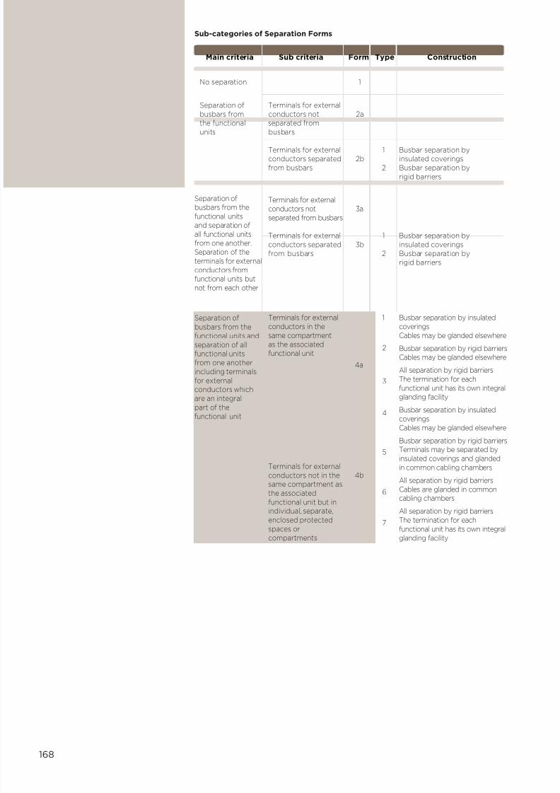
7/21/2019 TE Dorman Smith Product Portofolio 2011
http://slidepdf.com/reader/full/te-dorman-smith-product-portofolio-2011 170/182
168
Sub-categories of Separation Forms
Main criteria Sub criteria Form Type Construction
No separation 1
Separation of Terminals for externalbusbars from conductors not 2athe functional separated fromunits busbars
Terminals for external 1 Busbar separation byconductors separated 2b insulated coveringsfrom busbars 2 Busbar separation by
rigid barriers
Terminals for externalconductors not 3a
separated from busbars
Terminals for external 1 Busbar separation byconductors separated 3b insulated coveringsfrom busbars 2 Busbar separation by
rigid barriers
Terminals for externalconductors in thesame compartmentas the associatedfunctional unit
Busbar separation by insulatedcoveringsCables may be glanded elsewhere
Busbar separation by rigid barriersCables may be glanded elsewhere
All separation by rigid barriersThe termination for eachfunctional unit has its own integralglanding facility
Busbar separation by insulatedcoveringsCables may be glanded elsewhere
Busbar separation by rigid barriersTerminals may be separated byinsulated coverings and glandedin common cabling chambers
All separation by rigid barriersCables are glanded in commoncabling chambers
All separation by rigid barriersThe termination for eachfunctional unit has its own integralglanding facility
1
2
3
4
5
6
7
4a
4bTerminals for externalconductors not in thesame compartment asthe associatedfunctional unit but inindividual, separate,enclosed protectedspaces orcompartments
Separation ofbusbars from thefunctional unitsand separation ofall functional unitsfrom one another.Separation of theterminals for externalconductors from
functional units butnot from each other
Separation ofbusbars from thefunctional units andseparation of allfunctional unitsfrom one anotherincluding terminalsfor externalconductors whichare an integralpart of the
functional unit

7/21/2019 TE Dorman Smith Product Portofolio 2011
http://slidepdf.com/reader/full/te-dorman-smith-product-portofolio-2011 171/182
169
The EN 60529 standard describes a system for classifying degrees of protectionagainst the ingress of foreign bodies and harmful liquids. It is intended that thisstandard is applied to enclosures of low voltage (LV) electrical equipment. Theclassification scheme comprises a designation prefixed by the upper case letters’IP‘, followed by two numerals.
The first numeral designates the degree of protection with regard to solid objects;
the second numeral indicates the degree of protection against the ingress of liquid.Compliance to the standard is intended to:
• protect persons against access to hazardous parts inside enclosures and protectthe equipment inside the enclosure against the ingress of solid foreign objects.
• protect the equipment inside the enclosure against harmful ingress of liquids.
For assemblies for indoor use where there is no requirement for the protectionagainst ingress of water, the following IP codes are preferred: IP00, IP2X, IP3X,IP4X, IP5X, IP6X.
Ingress Protection
IP Protection Equivalent
0 No protection
1 Full entry of 50mm Back of sphere, but no hand contact with
hazardous parts
2 Full entry of 12.5mm Finger sphere not allowed, but no contact with hazardous parts with jointed test finger
3 2.5mm diameter Tool access probe shall
not enter
4 1mm diameter access Wire probe shall not enter
5 Limited ingress of Wire dust (no harmful
deposit)
6 Total protection Wire against dust ingress
X Not tested -
IP Protection Equivalent
0 No protection
1 Against vertically Verticalfalling water drops drips
2 As in 1, but with Slanted
enclosure tilted 15 drippingdegrees from vertical to 15
degrees from
vertical
3 Against spray to 60 Limiteddegrees from spray
vertical – limitedingress permitted
4 Against splashing Splashing from any direction – from any limited ingress direction permitted
5 Against low pressure Hosingjets from any jets fromdirection – limited anyingress permitted direction
6 Against strong jets Power from any direction hosing
from anydirection
7 Against immersion Temporary up to one metre immersion
8 Against prolonged Continuous immersion under immersion pressure
X Not tested -
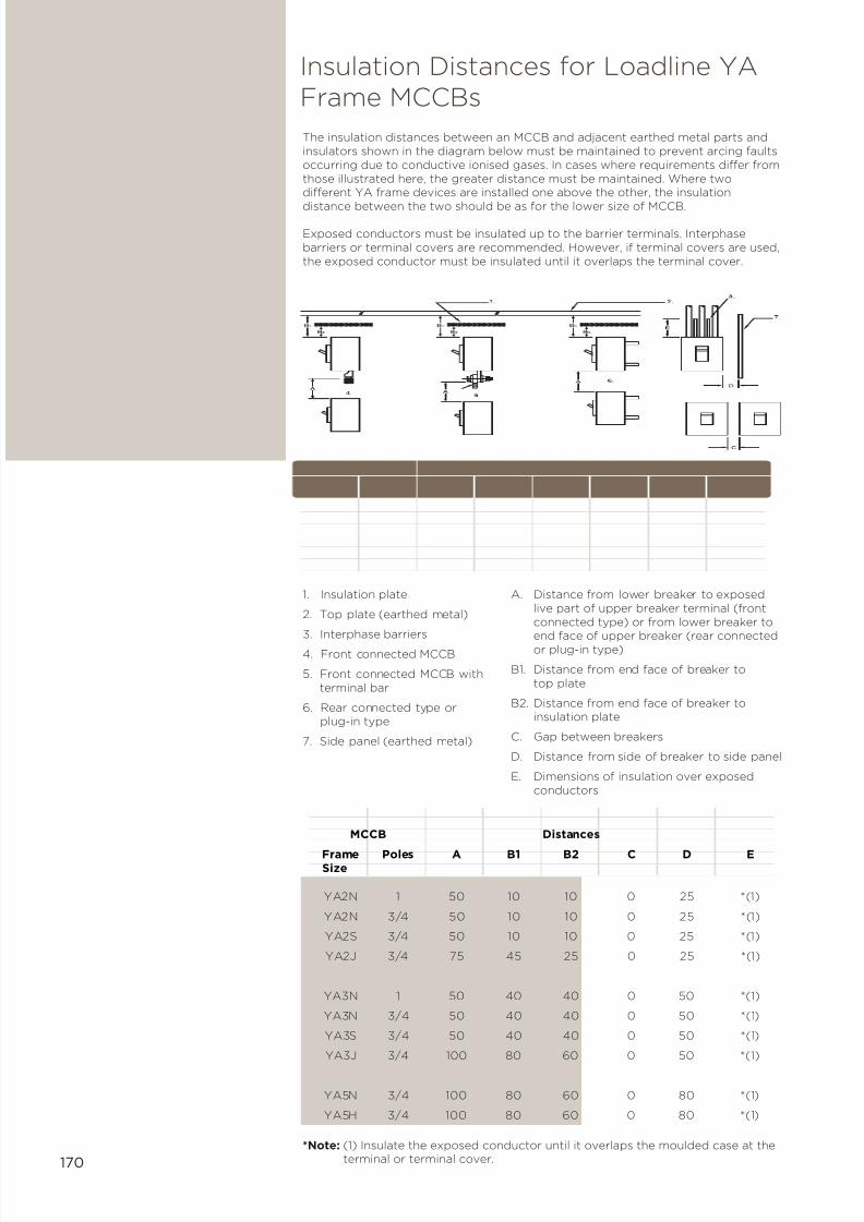
7/21/2019 TE Dorman Smith Product Portofolio 2011
http://slidepdf.com/reader/full/te-dorman-smith-product-portofolio-2011 172/182
170
The insulation distances between an MCCB and adjacent earthed metal parts andinsulators shown in the diagram below must be maintained to prevent arcing faultsoccurring due to conductive ionised gases. In cases where requirements differ fromthose illustrated here, the greater distance must be maintained. Where twodifferent YA frame devices are installed one above the other, the insulationdistance between the two should be as for the lower size of MCCB.
Exposed conductors must be insulated up to the barrier terminals. Interphasebarriers or terminal covers are recommended. However, if terminal covers are used,the exposed conductor must be insulated until it overlaps the terminal cover.
1. Insulation plate
2. Top plate (earthed metal)
3. Interphase barriers4. Front connected MCCB
5. Front connected MCCB withterminal bar
6. Rear connected type orplug-in type
7. Side panel (earthed metal)
*Note: (1) Insulate the exposed conductor until it overlaps the moulded case at theterminal or terminal cover.
A. Distance from lower breaker to exposedlive part of upper breaker terminal (frontconnected type) or from lower breaker to
end face of upper breaker (rear connectedor plug-in type)
B1. Distance from end face of breaker totop plate
B2. Distance from end face of breaker toinsulation plate
C. Gap between breakers
D. Distance from side of breaker to side panel
E. Dimensions of insulation over exposedconductors
MCCB Distances
Frame Poles A B1 B2 C D ESize
YA2N 1 50 10 10 0 25 *(1)
YA2N 3/4 50 10 10 0 25 *(1)
YA2S 3/4 50 10 10 0 25 *(1)
YA2J 3/4 75 45 25 0 25 *(1)
YA3N 1 50 40 40 0 50 *(1)
YA3N 3/4 50 40 40 0 50 *(1)
YA3S 3/4 50 40 40 0 50 *(1)
YA3J 3/4 100 80 60 0 50 *(1)
YA5N 3/4 100 80 60 0 80 *(1)
YA5H 3/4 100 80 60 0 80 *(1)
Insulation Distances for Loadline YAFrame MCCBs
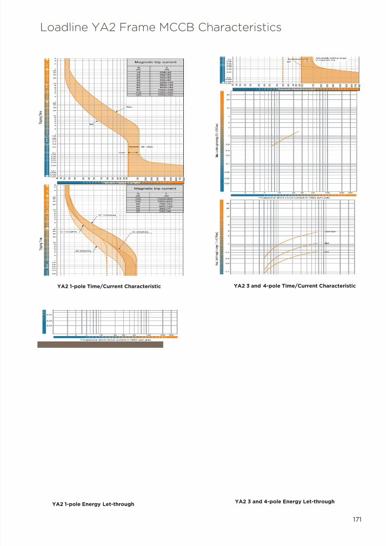
7/21/2019 TE Dorman Smith Product Portofolio 2011
http://slidepdf.com/reader/full/te-dorman-smith-product-portofolio-2011 173/182
171
YA2 1-pole Time/Current Characteristic
Loadline YA2 Frame MCCB Characteristics
YA2 1-pole Energy Let-throughYA2 3 and 4-pole Energy Let-through
YA2 3 and 4-pole Time/Current Characteristic

7/21/2019 TE Dorman Smith Product Portofolio 2011
http://slidepdf.com/reader/full/te-dorman-smith-product-portofolio-2011 174/182
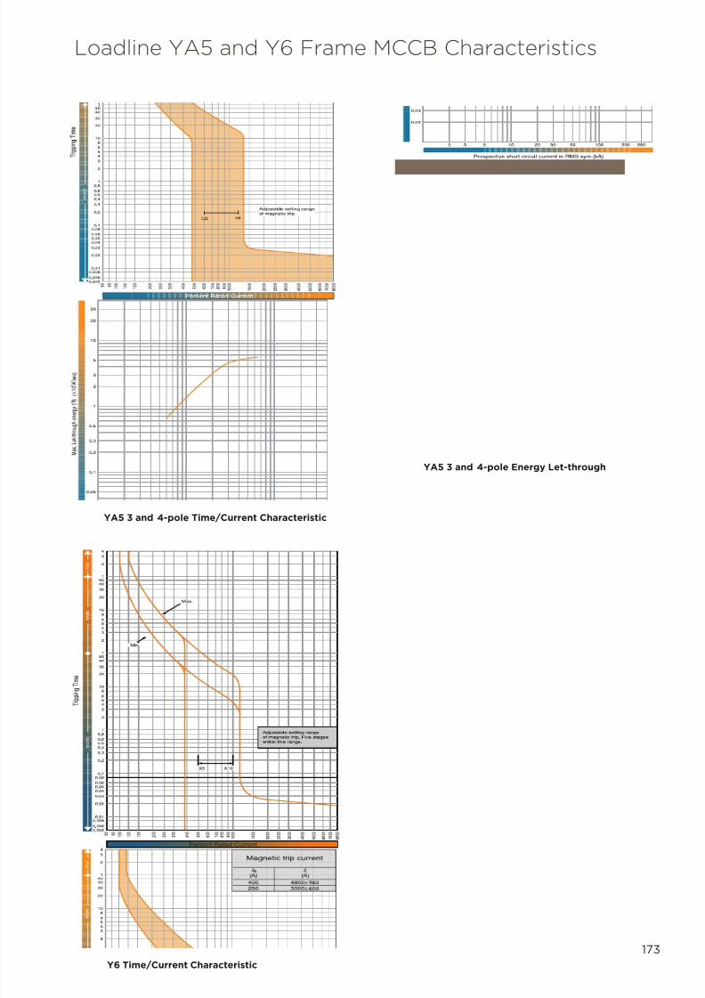
7/21/2019 TE Dorman Smith Product Portofolio 2011
http://slidepdf.com/reader/full/te-dorman-smith-product-portofolio-2011 175/182
173
Loadline YA5 and Y6 Frame MCCB Characteristics
YA5 3 and 4-pole Time/Current Characteristic
YA5 3 and 4-pole Energy Let-through
Y6 Time/Current Characteristic

7/21/2019 TE Dorman Smith Product Portofolio 2011
http://slidepdf.com/reader/full/te-dorman-smith-product-portofolio-2011 176/182
174
Loadline Y7 and Y8 Frame MCCBCharacteristics
Y7 Time/Current Characteristic
43
2
15040
30
20
108
6
54
3
2
15040
30
20
10
8
6
5
4
3
2
1
0.8
0.6
0.5
0.4
0.3
0.2
0.1
0.08
0.06
0.05
0.04
0.03
0.02
0.01
0.008
0.006
0.005
8 0
9 0
1 0 0
1 2 5
1 5
0
2 0 0
2 5
0
3 0 0
4 0 0
5 0 0
6 0 0
7 0 0
8 0 0
9 0 0
1 0 0 0
1 5
0 0
2 0 0 0
2 5
0 0
3 0 0 0 8 9
1 0
1 2
. 5
1 5
2 0
4 0
5 0
Curves based on standard settings
T
I
IG
I1
T1
I2 T2
I3TG
IP
Percent rated current of base current (I0)
Y8 Time/Current Characteristic

7/21/2019 TE Dorman Smith Product Portofolio 2011
http://slidepdf.com/reader/full/te-dorman-smith-product-portofolio-2011 177/182
10Section
Products & Parts Locator
7/21/2019 TE Dorman Smith Product Portofolio 2011
http://slidepdf.com/reader/full/te-dorman-smith-product-portofolio-2011 178/182
176
2IP-7-0244 116
3C345 01 124, 125
3G365 02 124, 125
AV2100 9, 118
AV2125 9, 118
AV3100 20, 118
AV3125 20, 118AV363 118
AV4100 20, 118
AV4125 20, 118
AV463 118
CBT-94F-035 123
CBT-94F-070 123
CBT-94F-105 123
CBT-94F-140 123
CI1-01-PUL 25, 51, 67, 124
CI3-01-PUL 25, 51, 67, 124
CI-MOD-01 25, 51, 67, 124, 125
CI-PUL-01 25, 51, 67, 124, 125
DA06X 8
DA09X 8
DA12X 8
DA15X 8
DA18X 8
DA22X 8
DAS08X 8
DAS11X 8
DAS14X 8
DAS17X 8
DAS20X 8
DAS24X 8
DAXD1 9
DAXEB 8
DAXEB 19
DAXSK08 8
DAXSK11 8
DAXSK14 8
DAXSK17 8
DAXSK20 8
DAXSK24 8
DAXTP 19
DBMSB 18, 26
DBS18X 18
DBS36X 18
DBTE04X 19
DBTE06X 19
DBTE08X 19
DBTE12X 19
DBTE16X 19
DBTE20X 19
DBTE24X 19
DBX04R 18
DBX06R 18
DBX08R 18
DBX12R 18
DBX16R 18
DBX20R 18
DBX24FK 19
DBX24R 18
DBX24WL 19
DBXBH 8, 11, 19
DBXBM 8, 11, 19
DBXBP 8, 11, 19
DBXC06NAH06CA 27
DBXC06NAV04CA 27DBXC08NAV06CA 27
DBXC08NJV06CJ 27
DBXC08NNV06CA 27
DBXC12NAH12CA 27
DBXC12NAV08CA 27
DBXC12NJV08CJ 27
DBXC12NNV08CA 27
DBXCKR 20
DBXCL 8, 19, 38, 39, 41, 60
DBXD0 9, 21
DBXD1 21
DBXD2 21
DBXE08NAH08NA 27
DBXE08NAV06NA 27
DBXE08NJV06NJ 27
DBXE12NAV08NA 27
DBXE12NJV08NJ 27
DBXEP 19
DBXJK 19
DBXL 8, 19
DBXLSA1 20
DBXLSA2 20
DBXPL 8, 19, 38, 39, 41, 60
DBXSKA 19
DBXT06 19
DBXT12 19
DBXT18 19
DBXT24 19
DBXTS 19
DBXW16 26
DBXW16T 26
DBXW24 26
DBXWP125 26
DBXWP250 26
DBXYA3 18
DRK-1P-230-D63 25, 127
DRK-1PCT-240 127
DRK-3P-400-D100 25, 127
DRK-3PCT-415 11, 25, 40, 127
DRK-3PCT-415-LCD 11, 25, 127
DRT-DW2R 24, 118
DSPE600 116
DSPE600N 116
DSPE600R 116
DSPM1P 115
DSPM1PN 9, 115
DSPM1PNR 115
DSPM3P 115
DSPM3PN 21, 115
DSPM3PNR 115
DSPML 9, 21, 115
DSPMNE 9, 21, 115
DSPT3PN 117
EE100/100/2 9, 24, 97
EE100/100/4 20, 24, 97
EE100/30/2 9, 24, 97
EE100/30/4 20, 24, 97
EE100/300/4 20, 24, 97
EE2P20CC 24, 118EE2P20CO 24, 118
EE40/100/2 97
EE40/100/4 20, 24, 97
EE40/30/2 24, 97
EE40/30/4 20, 24, 97
EE40/300/4 97
EE4P25CC 24, 118
EE4P25CO 24, 118
EE4P40CC 24, 118
EE4P40CO 24, 118
EE4P63CC 24, 118
EE4P63CO 20, 24, 118
EE63/100/2 9, 24, 97
EE63/100/4 20, 24, 97
EE63/30/2 9, 24, 97
EE63/30/4 20, 24, 97
EE63/300/2 9, 24, 97
EE63/300/4 20, 24, 97
EE80/30/2 9, 24, 97
EES100/100/2 9, 24, 97
EES100/100/4 20, 24, 97
EES63/100/4 20, 24
ELR1 122
FS2 85, 87
HB125CSB 85
HB200CSB 85
HB400CSB 85
HB800CSB 85
HBE3P32N 84
HBF3P100N 84
HBF3P100N 20
HBF3P125N 84
HBF3P160N 84
HBF3P200N 84
HBF3P200N 20
HBF3P63N 84
HBF4P100 84
HBF4P200 84
HBK3P315N 84
HBL3P400N 84
HBL4P400 84
HBN3P630N 84
HBN3P800N 84
HBN4P800 84
HEL32 85
HFL200A 49, 85, 87
HFL63 49, 85, 87
HLL400 49, 85, 87
HNL800 49, 85, 87

7/21/2019 TE Dorman Smith Product Portofolio 2011
http://slidepdf.com/reader/full/te-dorman-smith-product-portofolio-2011 179/182
7/21/2019 TE Dorman Smith Product Portofolio 2011
http://slidepdf.com/reader/full/te-dorman-smith-product-portofolio-2011 180/182
178
LEBM6 50, 66
LECK2SM 50, 67
LECK2SP 50, 67
LECM1 50, 67
LECM2 50, 67
LECM3 50, 67
LECM4 50, 67
LECM5 50, 67
LECM6 50, 67LECM8 50, 67
LECMD2 51, 67
LECMD3 51, 67
LECMD4 51, 67
LECMD5 51, 67
LECMD6 51, 67
LECMD8 51, 67
LF1F4A 48, 64
LF1F8A 48, 64
LF806A 48
LF806YA 64
LF810A 48
LF810YA 64
LFS41A 48
LFS41YA 64
LFS42A 48
LFS42YA 64
LFXHBA 48
LGES 60
LGES 61
LLMV 24, 118
LM10 114
LM20 114
LM30 114
LM3P20 114
LM3P30 114
LM40 114
LM50 114
LM60 114
LMMB2 114
LMMB3 114
LW3 114
M30-DINCLIP 11
M30-DINCLIP 119
M3N1-25-100/5 40, 120
M3N1-25-125/5 40, 120
M3N1-25-160/5 120
M3N1-25-60/5 40, 120
M3N1-35-100/5 26, 51, 67, 120
M3N1-35-125/5 26, 51, 67, 120
M3N1-35-160/5 120
M3N1-35-200/5 26
M3N1-35-250/5 26
M3N1-45-250/5 40
M3N1-45-250/5 120
M3N1-45-300/5 120
M3N1-45-400/5 40
M3N1-45-400/5 120
M3N1-45-500/5 120
M3N1-45-630/5 120
M50-DINCLIP 119
M53J-100/5D 119
M53J-125/5D 119
M53J-200/5D 119
M53J-250/5D 119
M53Q-100/5 11, 119
M53Q-125/5 11, 119
M55E-30/5 119
M55E-60/5 119M63N-400/5 51, 67, 119
M63N-600/5 51, 67
M93L-600/5 119
M93L-800/5 51, 67
MB5D-800/5 119
MCFMY6 64
MMS15Y 64
MXD06 48, 64
MXD10 48, 64
MXEPF 60
PB206YA 38
PB208YA 38
PB212YA 38
PB406YA 39
PB408YA 39
PB412YA 39
PB416YA 39
PB4PNC250 38, 41
PB4PNC400 39, 41
PBSM 40
PBWCT 40
PBWI 40
PBWM6 40
PBWP 40
PBYA2CSB 38
PBYA2MB 40
PBYA2OG 38
PBYA2SC24 38
PS100NY 90
PS125NY 90
PS16NY 90
PS25NY 90
PS32NY 90
PS40NY 90
PS63NY 90
PS80NY 90
RI3-01 11, 25, 40, 128
S1PB06 96
S1PB10 96
S1PB16 96
S1PB20 96
S1PB25 96
S1PB32 96
S1PB40 96
S1PB50 96
S1PB63 96
S1PC06 96
S1PC10 96
S1PC16 96
S1PC20 96
S1PC25 96
S1PC32 96
S1PC40 96
S1PC50 96
S1PC63 96
S1PD06 96
S1PD10 96S1PD16 96
S1PD20 96
S1PD25 96
S1PD32 96
S1PD40 96
S1PD50 96
S1PD63 96
S2PB06 96
S2PB10 96
S2PB16 96
S2PB20 96
S2PB25 96
S2PB32 96
S2PB40 96
S2PB50 96
S2PB63 96
S2PC06 96
S2PC10 96
S2PC16 96
S2PC20 96
S2PC25 96
S2PC32 96
S2PC40 96
S2PC50 96
S2PC63 96
S2PD06 96
S2PD10 96
S2PD16 96
S2PD20 96
S2PD25 96
S2PD32 96
S2PD40 96
S2PD50 96
S2PD63 96
S3PB06 96
S3PB10 96
S3PB16 96
S3PB20 96
S3PB25 96
S3PB32 96
S3PB40 96
S3PB50 96
S3PB63 96
S3PC06 96
S3PC10 96
S3PC16 96
S3PC20 96
S3PC25 96
S3PC32 96
S3PC40 96
S3PC50 96

7/21/2019 TE Dorman Smith Product Portofolio 2011
http://slidepdf.com/reader/full/te-dorman-smith-product-portofolio-2011 181/182
179
S3PC63 96
S3PD06 96
S3PD10 96
S3PD16 96
S3PD20 96
S3PD25 96
S3PD32 96
S3PD40 96
S3PD50 96S3PD63 96
SAUX2F 49, 85, 87
SAUX2N 49, 85, 87
SAUX4F 49, 85, 87
SAUX4N 49, 85, 87
SAUX6N 49, 85, 87
SC1-100/5A 121
SC1-150/5A 121
SC1-200/5A 121
SC1-250/5A 121
SC1-300/5A 121
SC1-400/5A 121
SC2-250/5A 121
SC2-300/5A 121
SC2-400/5A 121
SC3-1000/5A 121
SC3-250/5A 121
SC3-300/5A 121
SC3-400/5A 121
SC3-500/5A 121
SC3-600/5A 121
SC3-750/5A 121
SC3-800/5A 121
SC4-1000/5A 121
SC4-1200/5A 121
SC4-1250/5A 121
SC4-1500/5A 121
SC4-1600/5A 121
SC4-500/5A 121
SC4-600/5A 121
SC4-750/5A 121
SC4-800/5A 121
SCLK 85, 87
SF1P100N 49
SF1P125N 49
SF1P160N 49
SF1P200N 49
SF3P100N 49, 86
SF3P125N 49, 86
SF3P160N 49, 86
SF3P200N 49, 60, 86
SF3P63N 49, 86
SF4P100 49, 86
SF4P125 49, 86
SF4P160 49, 86
SF4P200 49, 60, 86
SF4P63 49, 86
SFFS125 87
SFFS200 87
SFTB 49, 87
SFTSL 87
SFTSS 49, 87
SHA1 87
SHA2 87
SHA3 87
SHA4 87
SK3P315N 86
SK4P315 86
SKFS 87
SKTB 87SKTS 87
SL3P400N 48, 60, 64, 86
SL4P400 48, 60, 86
SL4P400N 64
SLFS 87
SLTB 49, 87
SLTS 49, 87
SN3P630N 48, 66, 86
SN3P800N 48, 66, 86
SN4P630 48, 86
SN4P630N 66
SN4P800 48, 86
SN4P800N 66
SNCET 48, 49, 66, 87
SNFS 87
SNTS 49, 87
SRLB100 87
SRLB125 87
SRLB160 87
SRLB200 87
SRLB315 87
SRLB400 87
SRLB63 87
SRLB630 87
SRLB800 87
SXT127 87
SXT160 87
SXT227 87
SXT260 87
T1PD40 10, 22, 94
T1PD50 10, 22, 94
T1PD63 10, 22, 94
T2PD40 94
T2PD50 94
T2PD63 94
T3PD40 22, 94
T3PD50 22, 94
T3PD63 22, 94
XPL 11, 23, 95
Y2DL 41
Y5CF 110
Y5DCLCAM 110, 112, 113
Y5TB3P 110, 112, 113
Y5TB4P 110, 112, 113
Y6AC400 111
Y6AC630 111
Y6AC800 111
Y6AUX1 110
Y6AUX2 110
Y6AUXAL 110
Y6B3P400D 60, 66
Y6B3P630D 60, 109
Y6B3P800D 109
Y6B4P400D 60, 66
Y6B4P630D 60, 109
Y6B4P800D 109
Y6CC4P 110Y6CLDS1 110
Y6CLDS2 110
Y6DL 110
Y6H3P400T5 60, 66, 109
Y6H3P630E 109
Y6H3P630T5 60
Y6H3P800E 109
Y6H3P800T5 66, 109
Y6H4P400T5 60, 66, 109
Y6H4P630E 109
Y6H4P630T5 60
Y6H4P630T5 66, 109
Y6H4P800E 109
Y6H4P800T5 66, 109
Y6HE 110
Y6J3P630E 109
Y6J3P800E 109
Y6J4P630E 109
Y6J4P800E 109
Y6K3P400T5 109
Y6K3P630T5 109
Y6K3P800T5 109
Y6K4P400T5 109
Y6K4P630T5 109
Y6K4P800T5 109
Y6MA110 110
Y6MA240 110
Y6MMS 110
Y6MR 110
Y6MW10 110
Y6MW15 110
Y6NL 110
Y6RH1 110
Y6RH2 110
Y6ST115AC 110
Y6ST24DC 110
Y6ST480AC 110
Y6TS3P 110
Y6TS4P 110
Y6UVR120AC 110
Y6UVR240AC 110
Y6UVR24DC 110
Y6UVR450AC 110
Y7AUX3P1 112, 113
Y7AUX3P2 112, 113
Y7AUX3PAL 112, 113
Y7AUX4P1 112, 113
Y7AUX4P2 112, 113
Y7AUX4PAL 112, 113
Y7B3P1250D 112
Y7B3P800D 60

7/21/2019 TE Dorman Smith Product Portofolio 2011
http://slidepdf.com/reader/full/te-dorman-smith-product-portofolio-2011 182/182
Y7B4P1250D 112
Y7B4P800D 60
Y7CL 112, 113
Y7DL 112, 113
Y7J3P1000E 60, 112
Y7J3P1250E 112
Y7J4P1000E 60, 112
Y7J4P1250E 112
Y7MA110 112, 113Y7MA240 112, 113
Y7NL 112, 113
Y7ST115AC 112, 113
Y7ST24DC 112, 113
Y7ST480AC 112, 113
Y7TS3P 112, 113
Y7TS4P 112, 113
Y7UVR120AC 112, 113
Y7UVR240AC 112, 113
Y7UVR24DC 112, 113
Y7UVR450AC 112, 113
Y8B3P1600D 113
Y8B3P1600DDO - 113
Y8B3P1600DR - 113
Y8B4P1600D 113
Y8K3P1600E 113
Y8K3P1600EG 113
Y8K3P1600ER 113
Y8K4P1600E 113
YA2N4P50T 103
YA2N4P63T 103
YA2S3P100T 103
YA2S3P125T 103
YA2S3P50T 103
YA2S3P63T 103
YA2S4P100T 103
YA2S4P125T 103
YA2S4P50T 103YA2S4P63T 103
YA2TS1P 41
YA2TS3P 41
YA34J100T 105
YA34J125T 105
YA34J160T 105
YA34J200T 105
YA34J250T 105
YA34J63T 105
YA3B3P250D 21, 38, 60, 105
YA3B4P250D 21, 38, 60, 105
YA3CC3P 41, 62, 106
YA3CC4P 62, 106
YA3F4BP 64
YA3J3P100T 62, 65, 105
YA3J3P125T 62, 65, 105
YA3J3P160T 62, 65, 105
YA3J3P200T 62, 65, 105
YA3J3P250T 62 65 105
YA3N4P160T 21, 38, 60, 105
YA3N4P200T 21, 38, 60, 105
YA3N4P20T 105
YA3N4P250T 21, 38, 60, 105
YA3N4P32T 105
YA3N4P50T 63, 105
YA3N4P63T 21, 105
YA3NL 18, 60
YA3PB3P 106YA3PB4P 106
YA3PRA3P 106
YA3PRA4P 106
YA3PT3P 106
YA3PT4P 106
YA3PXT3P 106
YA3PXT4P 106
YA3R1 106
YA3R2 106
YA3RT3P 106
YA3RT4P 106
YA3S3P100T 62, 65, 105
YA3S3P125T 62, 65, 105
YA3S3P160T 62, 65, 105
YA3S3P200T 62, 65, 105
YA3S3P250T 62, 65, 105
YA3S3P50T 62, 65, 105
YA3S3P63T 62, 65, 105
YA3S4P100T 105