TDS200-, TDS1000-, and TDS2000-Series Digital …kieda/tk2002_prog.pdf · vi TDS200/1000/2000...
250
Programmer Manual TDS200-, TDS1000-, and TDS2000-Series Digital Oscilloscope 071-1075-00 This document supports TDS210 and TDS220 with FV:v1.09 and above when used with TDS2CM version CMV:v1.04 and above, or TDS2CMA and TDS2MM any version; TDS224, TDS1000- and TDS2000-series, all versions www.tektronix.com
Transcript of TDS200-, TDS1000-, and TDS2000-Series Digital …kieda/tk2002_prog.pdf · vi TDS200/1000/2000...

Programmer Manual
TDS200-, TDS1000-, and TDS2000-SeriesDigital Oscilloscope
071-1075-00
This document supports TDS210 and TDS220with FV:v1.09 and above when used withTDS2CM version CMV:v1.04 and above, orTDS2CMA and TDS2MM any version; TDS224,TDS1000- and TDS2000-series, all versions
www.tektronix.com

Copyright � Tektronix, Inc. All rights reserved. Licensed software productsare owned by Tektronix or its suppliers and are protected by United Statescopyright laws and international treaty provisions.
Use, duplication, or disclosure by the Government is subject to restrictions asset forth in subparagraph (c)(1)(ii) of the Rights in Technical Data andComputer Software clause at DFARS 252.227-7013, or subparagraphs (c)(1)and (2) of the Commercial Computer Software - Restricted Rights clause atFAR 52.227-19, as applicable.
Tektronix products are covered by U.S. and foreign patents, issued andpending. Information in this publication supercedes that in all previouslypublished material. Specifications and price change privileges reserved.
Tektronix, Inc., P.O. Box 500, Beaverton, OR 97077
TEKTRONIX and TEK are registered trademarks of Tektronix, Inc.

WARRANTY
Tektronix warrants that this product will be free from defects in materials andworkmanship for a period of three (3) years from the date of shipment. If any such productproves defective during this warranty period, Tektronix, at its option, either will repair thedefective product without charge for parts and labor, or will provide a replacement inexchange for the defective product.
In order to obtain service under this warranty, Customer must notify Tektronix of thedefect before the expiration of the warranty period and make suitable arrangements for theperformance of service. Customer shall be responsible for packaging and shipping thedefective product to the service center designated by Tektronix, with shipping chargesprepaid. Tektronix shall pay for the return of the product to Customer if the shipment is toa location within the country in which the Tektronix service center is located. Customershall be responsible for paying all shipping charges, duties, taxes, and any other charges forproducts returned to any other locations.
This warranty shall not apply to any defect, failure or damage caused by improper use orimproper or inadequate maintenance and care. Tektronix shall not be obligated to furnishservice under this warranty a) to repair damage resulting from attempts by personnel otherthan Tektronix representatives to install, repair or service the product; b) to repair damageresulting from improper use or connection to incompatible equipment; or c) to service aproduct that has been modified or integrated with other products when the effect of suchmodification or integration increases the time or difficulty of servicing the product.
THIS WARRANTY IS GIVEN BY TEKTRONIX IN LIEU OF ANY OTHERWARRANTIES, EXPRESS OR IMPLIED. TEKTRONIX AND ITS VENDORSDISCLAIM ANY IMPLIED WARRANTIES OF MERCHANTABILITY ORFITNESS FOR A PARTICULAR PURPOSE. TEKTRONIX’ RESPONSIBILITYTO REPAIR OR REPLACE DEFECTIVE PRODUCTS IS THE SOLE ANDEXCLUSIVE REMEDY PROVIDED TO THE CUSTOMER FOR BREACH OFTHIS WARRANTY. TEKTRONIX AND ITS VENDORS WILL NOT BE LIABLEFOR ANY INDIRECT, SPECIAL, INCIDENTAL, OR CONSEQUENTIALDAMAGES IRRESPECTIVE OF WHETHER TEKTRONIX OR THE VENDORHAS ADVANCE NOTICE OF THE POSSIBILITY OF SUCH DAMAGES.


TDS200/1000/2000 Series Oscilloscope Programmer Manual i
Table of Contents
Preface v. . . . . . . . . . . . . . . . . . . . . . . . . . . . . . . . . . . . . . . . . . . . Related Documents v. . . . . . . . . . . . . . . . . . . . . . . . . . . . . . . . . . Conventions vi. . . . . . . . . . . . . . . . . . . . . . . . . . . . . . . . . . . . . . . . Contacting Tektronix vii. . . . . . . . . . . . . . . . . . . . . . . . . . . . . . . . .
Getting Started
Getting Started 1-1. . . . . . . . . . . . . . . . . . . . . . . . . . . . . . . . . . . . .
Syntax and Commands
Command Syntax 2-1. . . . . . . . . . . . . . . . . . . . . . . . . . . . . . . . . . . Command and Query Structure 2-2. . . . . . . . . . . . . . . . . . . . . . . . . Command Entry 2-5. . . . . . . . . . . . . . . . . . . . . . . . . . . . . . . . . . . . . Constructed Mnemonics 2-8. . . . . . . . . . . . . . . . . . . . . . . . . . . . . . Argument Types 2-10. . . . . . . . . . . . . . . . . . . . . . . . . . . . . . . . . . . . .
Command Groups 2-15. . . . . . . . . . . . . . . . . . . . . . . . . . . . . . . . . . Acquisition Commands 2-15. . . . . . . . . . . . . . . . . . . . . . . . . . . . . . . Calibration and Diagnostic Commands 2-15. . . . . . . . . . . . . . . . . . . Cursor Commands 2-16. . . . . . . . . . . . . . . . . . . . . . . . . . . . . . . . . . . Display Commands 2-17. . . . . . . . . . . . . . . . . . . . . . . . . . . . . . . . . . Hard Copy Commands 2-18. . . . . . . . . . . . . . . . . . . . . . . . . . . . . . . Horizontal Commands 2-18. . . . . . . . . . . . . . . . . . . . . . . . . . . . . . . . Math Commands 2-19. . . . . . . . . . . . . . . . . . . . . . . . . . . . . . . . . . . . Measurement Commands 2-20. . . . . . . . . . . . . . . . . . . . . . . . . . . . . Miscellaneous Commands 2-21. . . . . . . . . . . . . . . . . . . . . . . . . . . . . RS-232 Commands 2-22. . . . . . . . . . . . . . . . . . . . . . . . . . . . . . . . . . Save and Recall Commands 2-23. . . . . . . . . . . . . . . . . . . . . . . . . . . Status and Error Commands 2-24. . . . . . . . . . . . . . . . . . . . . . . . . . . Trigger Commands 2-25. . . . . . . . . . . . . . . . . . . . . . . . . . . . . . . . . . Vertical Commands 2-26. . . . . . . . . . . . . . . . . . . . . . . . . . . . . . . . . . Waveform Commands 2-27. . . . . . . . . . . . . . . . . . . . . . . . . . . . . . . .

Table of Contents
ii TDS200/1000/2000 Series Oscilloscope Programmer Manual
Waveform Data Formats 2-29. . . . . . . . . . . . . . . . . . . . . . . . . . . Waveform Data Record 2-31. . . . . . . . . . . . . . . . . . . . . . . . . . . . Waveform Data Locations and Memory Allocation 2-32. . . . . . Waveform Preamble 2-32. . . . . . . . . . . . . . . . . . . . . . . . . . . . . . . Scaling Waveform Data 2-32. . . . . . . . . . . . . . . . . . . . . . . . . . . . Transferring Waveform Data 2-32. . . . . . . . . . . . . . . . . . . . . . . .
Command Descriptions 2-35. . . . . . . . . . . . . . . . . . . . . . . . . . . . . .
Status and Events
Status and Events 3-1. . . . . . . . . . . . . . . . . . . . . . . . . . . . . . . . . . . Registers 3-1. . . . . . . . . . . . . . . . . . . . . . . . . . . . . . . . . . . . . . . . . . .
Status Registers 3-1. . . . . . . . . . . . . . . . . . . . . . . . . . . . . . . . . . Enable Registers 3-4. . . . . . . . . . . . . . . . . . . . . . . . . . . . . . . . . . The Enable Registers and the *PSC Command 3-6. . . . . . . . .
Queues 3-6. . . . . . . . . . . . . . . . . . . . . . . . . . . . . . . . . . . . . . . . . . . . The Output Queue 3-6. . . . . . . . . . . . . . . . . . . . . . . . . . . . . . . . The Event Queue 3-7. . . . . . . . . . . . . . . . . . . . . . . . . . . . . . . . .
Event Handling Sequence 3-8. . . . . . . . . . . . . . . . . . . . . . . . . . . . . Synchronization Methods 3-10. . . . . . . . . . . . . . . . . . . . . . . . . . . . .
Using the *WAI Command 3-1 1. . . . . . . . . . . . . . . . . . . . . . . . . Using the BUSY Query 3-13. . . . . . . . . . . . . . . . . . . . . . . . . . . . Using the *OPC Set Command 3-14. . . . . . . . . . . . . . . . . . . . . . Using the *OPC? Query 3-16. . . . . . . . . . . . . . . . . . . . . . . . . . . .
Messages 3-17. . . . . . . . . . . . . . . . . . . . . . . . . . . . . . . . . . . . . . . . . .
Programming Example
Programming Example 4-1. . . . . . . . . . . . . . . . . . . . . . . . . . . . . .
Appendices
Appendix A: ASCII Code Chart A-1. . . . . . . . . . . . . . . . . . . . . . .
Appendix B: Factory Setup B-3. . . . . . . . . . . . . . . . . . . . . . . . . . .
Glossary and Index

Table of Contents
TDS200/1000/2000 Series Oscilloscope Programmer Manual iii
List of Figures
Figure 2-1: Command message elements 2-3. . . . . . . . . . . . . . .
Figure 2-2: Block argument example 2-13. . . . . . . . . . . . . . . . . .
Figure 3-1: The Standard Event Status Register (SESR) 3-2. .
Figure 3-2: The Status Byte Register (SBR) 3-3. . . . . . . . . . . . .
Figure 3-3: The Device Event Status Enable Register (DESER) 3-5. . . . . . . . . . . . . . . . . . . . . . . . . . . . . . . . . . . . . . .
Figure 3-4: The Event Status Enable Register (ESER) 3-5. . . .
Figure 3-5: The Service Request Enable Register (SRER) 3-5. . . . . . . . . . . . . . . . . . . . . . . . . . . . . . . . . . . . . . . . .
Figure 3-6: Status and event handling process 3-9. . . . . . . . . . .
Figure 3-7: Command processing without using synchronization 3-1 1. . . . . . . . . . . . . . . . . . . . . . . . . . . . . . . . . .
Figure 3-8: Processing sequence with synchronization 3-1 1. . . .
List of Tables
Table 2-1: BNF notation 2-1. . . . . . . . . . . . . . . . . . . . . . . . . . . .
Table 2-2: Command message elements 2-2. . . . . . . . . . . . . . . .
Table 2-3: Comparison of Header Off and Header On responses 2-5. . . . . . . . . . . . . . . . . . . . . . . . . . . . . . . . . . . . . .
Table 2-4: Types of numeric arguments 2-10. . . . . . . . . . . . . . . .
Table 2-5: Oscilloscope handling of incorrect numeric arguments 2-1 1. . . . . . . . . . . . . . . . . . . . . . . . . . . . . . . . . . . . . .
Table 2-6: Parts of a block argument 2-12. . . . . . . . . . . . . . . . . .
Table 2-7: Acquisition commands 2-15. . . . . . . . . . . . . . . . . . . . .
Table 2-8: Calibration and Diagnostic commands 2-16. . . . . . .

Table of Contents
iv TDS200/1000/2000 Series Oscilloscope Programmer Manual
Table 2-9: Cursor commands 2-16. . . . . . . . . . . . . . . . . . . . . . . .
Table 2-10: Display commands 2-17. . . . . . . . . . . . . . . . . . . . . . .
Table 2-11: Hard Copy commands 2-18. . . . . . . . . . . . . . . . . . . .
Table 2-12: Horizontal commands 2-18. . . . . . . . . . . . . . . . . . . .
Table 2-13: Math commands 2-19. . . . . . . . . . . . . . . . . . . . . . . . .
Table 2-14: Measurement commands 2-20. . . . . . . . . . . . . . . . . .
Table 2-15: Miscellaneous commands 2-21. . . . . . . . . . . . . . . . .
Table 2-16: RS-232 commands 2-23. . . . . . . . . . . . . . . . . . . . . . .
Table 2-17: Save and Recall commands 2-23. . . . . . . . . . . . . . . .
Table 2-18: Status and Error commands 2-24. . . . . . . . . . . . . . .
Table 2-19: Trigger commands 2-25. . . . . . . . . . . . . . . . . . . . . . .
Table 2-20: Vertical commands 2-26. . . . . . . . . . . . . . . . . . . . . . .
Table 2-21: Waveform commands 2-27. . . . . . . . . . . . . . . . . . . .
Table 2-22: Binary data ranges 2-31. . . . . . . . . . . . . . . . . . . . . . .
Table 2-23: Vertical position ranges using a 1X probe 2-54. . . .
Table 2-24: DATa and WFMPre parameter settings 2-70. . . . .
Table 2-25: Commands that generate an Operation Complete message 2-121. . . . . . . . . . . . . . . . . . . . . . . . . . . . . . .
Table 2-26: Additional WFMPre commands 2-173. . . . . . . . . . . .
Table 3-1: SESR bit functions 3-2. . . . . . . . . . . . . . . . . . . . . . . .
Table 3-2: SBR bit functions 3-4. . . . . . . . . . . . . . . . . . . . . . . . .
Table 3-3: No event messages 3-17. . . . . . . . . . . . . . . . . . . . . . . .
Table 3-4: Command error messages – CME bit 5 3-18. . . . . . .
Table 3-5: Execution error messages – EXE bit 4 3-18. . . . . . . .
Table 3-6: Device error messages – DDE bit 3 3-21. . . . . . . . . .
Table 3-7: System event messages 3-22. . . . . . . . . . . . . . . . . . . . .
Table 3-8: Execution warning messages – EXE bit 4 3-23. . . . .
Table 3-9: Internal warning messages 3-24. . . . . . . . . . . . . . . . .

TDS200/1000/2000 Series Oscilloscope Programmer Manual v
Preface
This programmer manual provides information on how to operateyour TDS 200-, TDS1000- or TDS2000-series digital oscilloscopewith the RS-232 or General Purpose Interface Bus (GPIB) protocols.
Related Documents
The TDS1000- and TDS2000-series oscilloscopes offer the followingstandard and optional documents:
� For information on the general operation of the oscilloscopes andhow to use a TDS2CMA communications module with theoscilloscope, refer to the TDS1000- and TDS2000-Series DigitalStorage Oscilloscope User Manual, a standard accessoryavailable in eleven languages as follows:
Language User manual part number
English 071−1064−XX
French 071−1065−XX*
Italian 071−1066−XX*
German 071−1067−XX*
Spanish 071−1068−XX*
Japanese 071−1069−XX*
Portuguese 071−1070−XX*
Simplified Chinese 071−1071−XX*
Traditional Chinese 071−1072−XX*
Korean 071−1073−XX*
Russian 071−1074−XX
* Contains a language overlay for the front−panel controls.

Preface
vi TDS200/1000/2000 Series Oscilloscope Programmer Manual
� For information on how to service the oscilloscope, refer to theTDS1000- and TDS2000-Series Digital Storage OscilloscopesService Manual (071-1076-XX), an optional accessory in Englishonly
The TDS200-series oscilloscopes offer the following standard andoptional documents:
� For information on the general operation of the oscilloscopes,refer to the TDS200-Series Digital Real-Time Oscilloscope UserManual, a standard accessory available in eleven languages
� For information on how to use a TDS2CMA communicationsmodule, or a TDS2MM measurements module with theoscilloscope, refer to the TDS200 Series Extension ModulesInstructions Manual (071-0409-XX), a standard accessory forextension modules in English only
� For information on how to service the oscilloscope, refer to theTDS200-Series Digital Real-Time Oscilloscopes Service Manual(071-0492-XX), an optional accessory in English only
Conventions
Refer to the Command Syntax section of the Syntax and Commandschapter (page 2-1) for information about command conventions.
NOTE. References to the TDS2CMA Communications ExtensionModule in this manual also apply to the TDS2CM extension module.
Preface
TDS200/1000/2000 Series Oscilloscope Programmer Manual vii
Contacting Tektronix
Phone 1-800-833-9200*
Address Tektronix, Inc.Department or name (if known)14200 SW Karl Braun DriveP.O. Box 500Beaverton, OR 97077USA
Web site www.tektronix.com
Sales support
1-800-833-9200, select option 1*
Service support 1-800-833-9200, select option 2*
Technical support
Email: [email protected]
1-800-833-9200, select option 3*
6:00 a.m. - 5:00 p.m. Pacific time
* This phone number is toll free in North America. After officehours, please leave a voice mail message.Outside North America, contact a Tektronix sales office ordistributor; see the Tektronix web site for a list of offices.

Preface
viii TDS200/1000/2000 Series Oscilloscope Programmer Manual

Getting Started

TDS200/1000/2000 Series Oscilloscope Programmer Manual 1−1
Getting Started
Before you use the commands in this programming manual toremotely control your oscilloscope, you must have installed aTDS2CMA Communications Extension Module onto your TDS1000or TDS2000 oscilloscope. Follow the instructions in the TDS1000-and TDS2000-Series Digital Storage Oscilloscope User Manual toinstall, test, and configure your extension module. You can also referto this manual for general information on how to operate a TDS1000or TDS2000 oscilloscope.
NOTE. References to the TDS2CMA Communications ExtensionModule in this manual also apply to the TDS2CM extension module.
The TDS1000- and TDS2000-series oscilloscopes include all of theMath and measurement functions of the TDS2MM extension module.
For a TDS200 oscilloscope, you must have installed a TDS2CMACommunications Extension Module or TDS2MM MeasurementExtension Module. Follow the instructions in the TDS200 SeriesExtension Module Instructions Manual to install, test, and configureyour extension module.
Refer to the TDS200-Series Digital Real-Time Oscilloscope UserManual for general information on how to operate a TDS200oscilloscope.

Getting Started
1−2 TDS200/1000/2000 Series Oscilloscope Programmer Manual
Syntax and Commands


TDS200/1000/2000 Series Oscilloscope Programmer Manual 2−1
Command Syntax
You can control the oscilloscope through the GPIB or RS-232interface using a large group of commands and queries. This sectiondescribes the syntax these commands and queries use and theconventions the oscilloscope uses to process them. The commandsand queries themselves are listed in the Command Descriptionssection.
You transmit commands to the oscilloscope using the enhancedAmerican Standard Code for Information Interchange (ASCII)character encoding. Appendix A contains a chart of the ASCIIcharacter set.
The Backus-Naur Form (BNF) notation is used in this manual todescribe commands and queries. Table 2-1 lists the BNF notation.
Table 2−1: BNF notation
Symbol Meaning
< > Defined element
::= Is defined as
| Exclusive OR
{ } Group; one element is required
[ ] Optional; can be omitted
. . . Previous element(s) may berepeated
( ) Comment

Command Syntax
2−2 TDS200/1000/2000 Series Oscilloscope Programmer Manual
Command and Query Structure
Commands consist of set commands and query commands (usuallysimply called commands and queries). Commands change oscillo-scope settings or perform a specific action. Queries cause theoscilloscope to return data and information about its status.
Most commands have both a set form and a query form. The queryform of the command is the same as the set form except that it endswith a question mark. For example, the set command ACQuire:MODehas a query form ACQuire:MODe?. Not all commands have both a setand a query form; some commands are set only and some are queryonly.
A few commands do both a set and query action. For example, the*CAL? command runs a self-calibration program on the oscilloscope,then returns the result of the calibration.
A command message is a command or query name, followed by anyinformation the oscilloscope needs to execute the command or query.Command messages consist of five different element types.
Table 2-2 lists and describes the five element types.
Table 2−2: Command message elements
Symbol Meaning
<Header> The basic command name. If the header ends witha question mark, the command is a query. Theheader may begin with a colon (:) character; if thecommand is concatenated with other commands thebeginning colon is required. The beginning coloncan never be used with command headersbeginning with a star (*).
<Mnemonic> A header subfunction. Some command headershave only one mnemonic. If a command header hasmultiple mnemonics, they are always separatedfrom each other by a colon (:) character.

Command Syntax
TDS200/1000/2000 Series Oscilloscope Programmer Manual 2−3
Table 2−2: Command message elements (Cont.)
Symbol Meaning
<Argument> A quantity, quality, restriction, or limit associated withthe header. Not all commands have an argument,while other commands have multiple arguments.Arguments are separated from the header by a<Space>. Arguments are separated from eachother by a <Comma>.
<Comma> A single comma between arguments of multiple−ar−gument commands. It may optionally have whitespace characters before and after the comma.
<Space> A white space character between command headerand argument. It may optionally consist of multiplewhite space characters.
Figure 2-1 shows the five command message elements.
Comma
SAVe:WAVEform CH1,REFA
Header
Mnemonics Arguments
Space
Figure 2−1: Command message elements
Command Syntax
2−4 TDS200/1000/2000 Series Oscilloscope Programmer Manual
Commands
Commands cause the oscilloscope to perform a specific function orchange one of its settings. Commands have the structure:
[:]<Header>[<Space><Argument>[<Comma><Argument>]...]
A command header is made up of one or more mnemonics arrangedin a hierarchical or tree structure. The first mnemonic is the base orroot of the tree and each subsequent mnemonic is a level or branchoff of the previous one. Commands at a higher level in the tree mayaffect those at a lower level. The leading colon (:) always returnsyou to the base of the command tree.
Queries
Queries cause the oscilloscope to return information about its statusor settings. Queries have the structure:
[:]<Header>?
[:]<Header>?[<Space><Argument>[<Comma><Argument>]...]
You can specify a query command at any level within the commandtree unless otherwise noted. These branch queries return informationabout all the mnemonics below the specified branch or level. Forexample, MEASUrement:MEAS<x>:UNIts? returns the measurementunits, while MEASUrement:MEAS<x>:TYPe? returns the measurementtype selected for the measurement, and MEASUrement:MEAS<x>?returns all the measurement parameters for the specified measure-ment.
Headers in Query Responses
You can control whether the oscilloscope returns headers as part ofthe query response. Use the HEADer command to control this feature.If header is on, the oscilloscope returns command headers as part ofthe query and formats the query response as a valid set command.When header is off, the oscilloscope sends back only the values inthe response. This format can make it easier to parse and extract theinformation from the response.
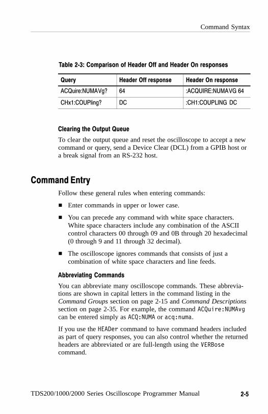
Table 2-3 shows the difference in responses.
Command Syntax
TDS200/1000/2000 Series Oscilloscope Programmer Manual 2−5
Table 2−3: Comparison of Header Off and Header On responses
Query Header Off response Header On response
ACQuire:NUMAVg? 64 :ACQUIRE:NUMAVG 64
CHx1:COUPling? DC :CH1:COUPLING DC
Clearing the Output Queue
To clear the output queue and reset the oscilloscope to accept a newcommand or query, send a Device Clear (DCL) from a GPIB host ora break signal from an RS-232 host.
Command Entry
Follow these general rules when entering commands:
� Enter commands in upper or lower case.
� You can precede any command with white space characters.White space characters include any combination of the ASCIIcontrol characters 00 through 09 and 0B through 20 hexadecimal(0 through 9 and 11 through 32 decimal).
� The oscilloscope ignores commands that consists of just acombination of white space characters and line feeds.
Abbreviating Commands
You can abbreviate many oscilloscope commands. These abbrevia-tions are shown in capital letters in the command listing in theCommand Groups section on page 2-15 and Command Descriptionssection on page 2-35. For example, the command ACQuire:NUMAvgcan be entered simply as ACQ:NUMA or acq:numa.
If you use the HEADer command to have command headers includedas part of query responses, you can also control whether the returnedheaders are abbreviated or are full-length using the VERBosecommand.
Command Syntax
2−6 TDS200/1000/2000 Series Oscilloscope Programmer Manual
Concatenating Commands
You can concatenate any combination of set commands and queriesusing a semicolon (;). The oscilloscope executes concatenatedcommands in the order received. When concatenating commandsand queries you must follow these rules:
� Completely different headers must be separated by both asemicolon and by the beginning colon on all commands but thefirst. For example, the commands TRIGger:MODe NORMal andACQuire:NUMAVg 16 can be concatenated into a singlecommand:
TRIGger:MODe NORMal;:ACQuire:NUMAVg 16
� If concatenated commands have headers that differ by only thelast mnemonic, you can abbreviate the second command andeliminate the beginning colon. For example, the commandsACQuire:MODe AVErage and ACQuire:NUMAVg 16 could beconcatenated into a single command:
ACQuire:MODe AVErage; NUMAVg 16
The longer version works equally well:
ACQuire:MODe AVErage;:ACQuire:NUMAVg 16
� Never precede a star (*) command with a colon:
ACQuire:MODe AVErage;*TRG
The oscilloscope processes commands that follow the starcommand as if the star command was not there, so:
ACQuire:MODe AVErage;*TRG;NUMAVg 16
sets the acquisition mode to average and sets acquisitionaveraging to 16. The *TRG command is ignored.
Command Syntax
TDS200/1000/2000 Series Oscilloscope Programmer Manual 2−7
� When you concatenate queries, the responses to all queries arecombined into a single response message. For example, ifchannel 1 coupling is set to DC and the bandwidth is set to20 MHz, the concatenated query:
CH1:COUPling?;BANdwidth?
returns :CH1:COUPLING DC;:CH1:BANDWIDTH ON if header is on,or DC;ON if header is off.
� You can concatenate set commands and queries in the samemessage. For example:
ACQuire:MODe AVErage;NUMAVg?;STATE?
is a valid message that sets the acquisition mode to normal,queries the number of acquisitions for averaging, and thenqueries the acquisition state. The oscilloscope executesconcatenated commands and queries in the order it receivesthem.
� Any query that returns arbitrary data, such as ID?, must be thelast query when part of a concatenated command. If the query isnot last, the oscilloscope generates event message 440.
Here are some INVALID concatenation examples:
� CH1:COUPling DC;ACQuire:NUMAVg 16(missing colon before ACQuire)
� CH1:COUPling DC;:BANDwidth ON(invalid colon before BANDwidth)
� CH1:COUPling DC;:*TRG(invalid colon before a star (*) command)
� HORizontal:MAIn:POSition 0;MAIn:SCAle 1E–13(levels of mnemonics are different—either remove the secondoccurrence of MAIn:, or put :HORizontal: in front ofMAIN:SCAle)

Command Syntax
2−8 TDS200/1000/2000 Series Oscilloscope Programmer Manual
Message Terminators
This manual uses the term <EOM> (End of message) to represent amessage terminator.
GPIB End of Message Terminators. GPIB EOM terminators can be theEND message (EOI asserted concurrently with the last data byte),the ASCII code for line feed (LF) sent as the last data byte, or both.The oscilloscope always terminates messages with LF and EOI.White space is allowed before the terminator; for example, CR LF isacceptable.
RS−232 End of Message Terminators. RS-232 EOM terminators can be aCR (carriage return), LF (line feed), CRLF (carriage return followedby a line feed), or LFCR (line feed followed by a carriage return).When receiving, the oscilloscope accepts all four combinations asvalid input message terminators regardless of the currently selectedterminator. When a combination of multiple characters is selected(CRLF or LFCR), the oscilloscope interprets the first character as theterminator and the second character as a null command.
Constructed Mnemonics
Some header mnemonics specify one of a range of mnemonics. Forexample, a channel mnemonic could be CH2. You can use thesemnemonics in the command just as you do any other mnemonic. Forexample, there is a CH1:VOLts command and there is also aCH2:VOLts command. In the command descriptions, this list ofchoices is abbreviated CH<x>.
Channel Mnemonics
Commands specify the channel to use as a mnemonic in the header.
Symbol Meaning
CH<x> 2−channel models: A channel specifier; <x> is 1 or 2.
4−channel models: A channel specifier; <x> is 1, 2,3, or 4.
Command Syntax
TDS200/1000/2000 Series Oscilloscope Programmer Manual 2−9
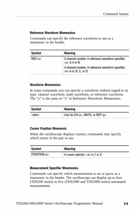
Reference Waveform Mnemonics
Commands can specify the reference waveform to use as amnemonic in the header.
Symbol Meaning
REF<x> 2−channel models: A reference waveform specifier;<x> is A or B.
4−channel models: A reference waveform specifier;<x> is A, B, C, or D.
Waveform Mnemonics
In some commands you can specify a waveform without regard to itstype: channel waveform, math waveform, or reference waveform.The “y” is the same as “x” in Reference Waveform Mnemonics.
Symbol Meaning
<wfm> Can be CH<x>, MATH, or REF<y>
Cursor Position Mnemonic
When the oscilloscope displays cursors, commands may specifywhich cursor of the pair to use.
Symbol Meaning
POSITION<x> A cursor selector; <x> is 1 or 2.
Measurement Specifier Mnemonics
Commands can specify which measurement to set or query as amnemonic in the header. The oscilloscope can display up to four(TDS200 series) or five (TDS1000 and TDS2000 series) automatedmeasurements.

Command Syntax
2−10 TDS200/1000/2000 Series Oscilloscope Programmer Manual
Symbol Meaning
MEAS<x> A measurement specifier; <x> is 1−4 (TDS200Series) or 1−5 (TDS1000 and TDS2000 series).
Argument Types
A command argument can be in one of several forms. The individualdescriptions of each command tell which argument types to use withthat command.
Numeric Arguments
Many oscilloscope commands require numeric arguments. Table 2-4lists the three types of numeric argument.
Table 2−4: Types of numeric arguments
Symbol Meaning
<NR1> Signed integer value
<NR2> Floating point value without an exponent
<NR3> Floating point value with an exponent
The syntax shown is the data format that the oscilloscope returns inresponse to a query. This format is also the preferred format whensending a command to the oscilloscope.
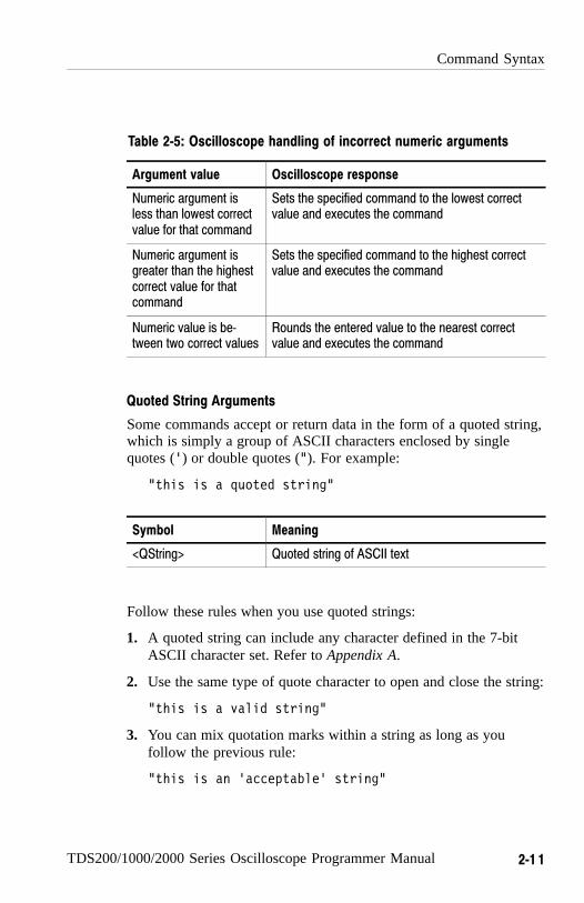
When you enter an incorrect numeric argument, the oscilloscopeautomatically forces the numeric argument to a correct value. Table 2-5 lists how the oscilloscope handles incorrect numericarguments.
Command Syntax
TDS200/1000/2000 Series Oscilloscope Programmer Manual 2−1 1
Table 2−5: Oscilloscope handling of incorrect numeric arguments
Argument value Oscilloscope response
Numeric argument isless than lowest correctvalue for that command
Sets the specified command to the lowest correctvalue and executes the command
Numeric argument isgreater than the highestcorrect value for thatcommand
Sets the specified command to the highest correctvalue and executes the command
Numeric value is be−tween two correct values
Rounds the entered value to the nearest correctvalue and executes the command
Quoted String Arguments
Some commands accept or return data in the form of a quoted string,which is simply a group of ASCII characters enclosed by singlequotes (’) or double quotes ("). For example:
"this is a quoted string"
Symbol Meaning
<QString> Quoted string of ASCII text
Follow these rules when you use quoted strings:
1. A quoted string can include any character defined in the 7-bitASCII character set. Refer to Appendix A.
2. Use the same type of quote character to open and close the string:
"this is a valid string"
3. You can mix quotation marks within a string as long as youfollow the previous rule:
"this is an ’acceptable’ string"

Command Syntax
2−12 TDS200/1000/2000 Series Oscilloscope Programmer Manual
4. You can include a quote character within a string simply byrepeating the quote. For example,
"here is a "" mark"
5. Strings can have upper or lower case characters.
6. If you use a GPIB network, you cannot terminate a quoted stringwith the END message before the closing delimiter.
7. A carriage return or line feed embedded in a quoted string doesnot terminate the string, but is treated as just another character inthe string.
8. The maximum length of a quoted string returned from a query is1000 characters.
Here are some examples of invalid strings:
"Invalid string argument’(quotes are not of the same type)
"test<EOI>"(termination character is embedded in the string)
Block Arguments
Several oscilloscope commands use a block argument form. Table 2-6 lists and describes each part of a block argument.
Table 2−6: Parts of a block argument
Symbol Meaning
<NZDig> A non−zero digit character, in the range 1–9Specifies the number of <Dig> elements that fo
<Dig> A digit character, in the range 0–9
<DChar> A character with the hex equivalent of 00 through FF hexadecimal(0 through 255 decimal)
<Block> A block of data bytes, defined as:
<Block> ::= { #<NZDig><Dig>[<Dig>...][<DChar>...]| #0[<DChar>...]<terminator> }

Command Syntax
TDS200/1000/2000 Series Oscilloscope Programmer Manual 2−13
Figure 2-2 shows an example of a block argument.
*DDT #217ACQuire:STATE RUN
Block header
Specifies number oflength digits that follow
Specifies data length
Block argument
Figure 2−2: Block Argument example
<NZDig> specifies the number of <Dig> elements that follow. Takentogether, the <Dig> elements form a decimal integer that specifieshow many <DChar> elements follow.
#0 means that the <Block> is an indefinite length block. The<terminator> ends the block. You should not use indefinite lengthblocks with RS-232, because there is no way to include a <termina−tor> character as a <DChar> character.
The first occurrence of a <terminator> character signals the end ofthe block and any subsequent <DChar> characters will be interpretedas a syntax error. With the GPIB, the EOI line signals the last byte.

Command Syntax
2−14 TDS200/1000/2000 Series Oscilloscope Programmer Manual
TDS200/1000/2000 Series Oscilloscope Programmer Manual 2−15
Command Groups
This section lists the commands organized by functional group. TheCommand Descriptions section, starting on page 2-35, lists allcommands alphabetically.
The oscilloscope GPIB and RS-232 interfaces conform to Tektronixstandard codes and formats except where noted. The GPIB interfacealso conforms to IEEE Std 488.2–1987 except where noted.
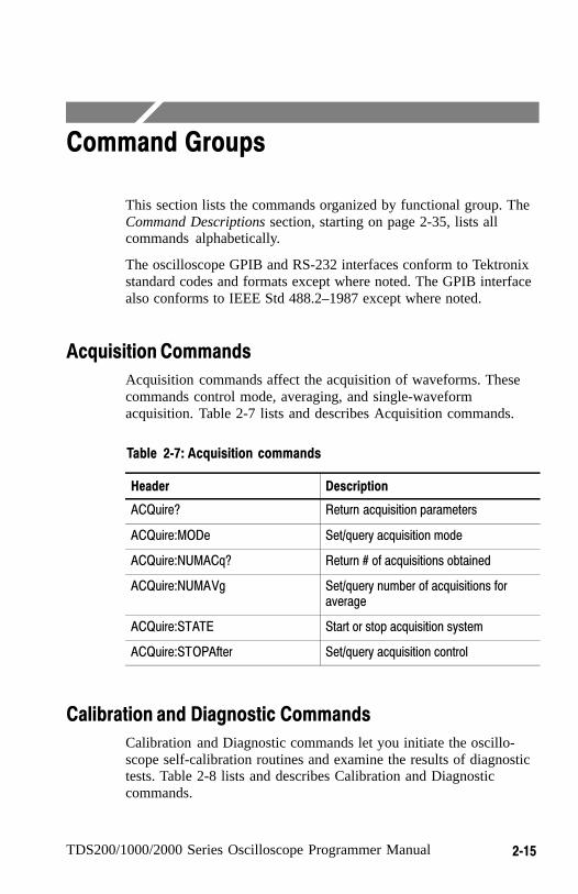
Acquisition Commands
Acquisition commands affect the acquisition of waveforms. Thesecommands control mode, averaging, and single-waveformacquisition. Table 2-7 lists and describes Acquisition commands.
Table 2−7: Acquisition commands
Header Description
ACQuire? Return acquisition parameters
ACQuire:MODe Set/query acquisition mode
ACQuire:NUMACq? Return # of acquisitions obtained
ACQuire:NUMAVg Set/query number of acquisitions foraverage
ACQuire:STATE Start or stop acquisition system
ACQuire:STOPAfter Set/query acquisition control
Calibration and Diagnostic Commands
Calibration and Diagnostic commands let you initiate the oscillo-scope self-calibration routines and examine the results of diagnostictests. Table 2-8 lists and describes Calibration and Diagnosticcommands.
Command Groups
2−16 TDS200/1000/2000 Series Oscilloscope Programmer Manual
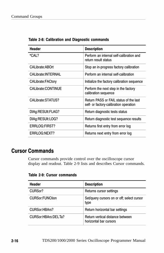
Table 2−8: Calibration and Diagnostic commands
Header Description
*CAL? Perform an internal self−calibration andreturn result status
CALibrate:ABOrt Stop an in−progress factory calibration
CALibrate:INTERNAL Perform an internal self−calibration
CALibrate:FACtory Initialize the factory calibration sequence
CALibrate:CONTINUE Perform the next step in the factorycalibration sequence
CALibrate:STATUS? Return PASS or FAIL status of the lastself− or factory−calibration operation
DIAg:RESUlt:FLAG? Return diagnostic tests status
DIAg:RESUlt:LOG? Return diagnostic test sequence results
ERRLOG:FIRST? Returns first entry from error log
ERRLOG:NEXT? Returns next entry from error log
Cursor Commands
Cursor commands provide control over the oscilloscope cursordisplay and readout. Table 2-9 lists and describes Cursor commands.
Table 2−9: Cursor commands
Header Description
CURSor? Returns cursor settings
CURSor:FUNCtion Set/query cursors on or off; select cursortype
CURSor:HBArs? Return horizontal bar settings
CURSor:HBArs:DELTa? Return vertical distance betweenhorizontal bar cursors
Command Groups
TDS200/1000/2000 Series Oscilloscope Programmer Manual 2−17
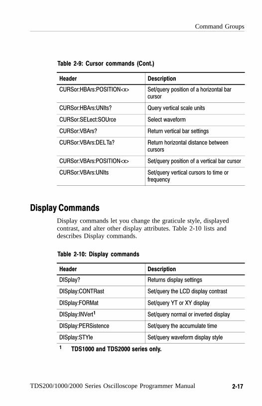
Table 2−9: Cursor commands (Cont.)
Header Description
CURSor:HBArs:POSITION<x> Set/query position of a horizontal barcursor
CURSor:HBArs:UNIts? Query vertical scale units
CURSor:SELect:SOUrce Select waveform
CURSor:VBArs? Return vertical bar settings
CURSor:VBArs:DELTa? Return horizontal distance betweencursors
CURSor:VBArs:POSITION<x> Set/query position of a vertical bar cursor
CURSor:VBArs:UNIts Set/query vertical cursors to time orfrequency
Display Commands
Display commands let you change the graticule style, displayedcontrast, and alter other display attributes. Table 2-10 lists anddescribes Display commands.
Table 2−10: Display commands
Header Description
DISplay? Returns display settings
DISplay:CONTRast Set/query the LCD display contrast
DISplay:FORMat Set/query YT or XY display
DISplay:INVert1 Set/query normal or inverted display
DISplay:PERSistence Set/query the accumulate time
DISplay:STYle Set/query waveform display style
1 TDS1000 and TDS2000 series only.
Command Groups
2−18 TDS200/1000/2000 Series Oscilloscope Programmer Manual
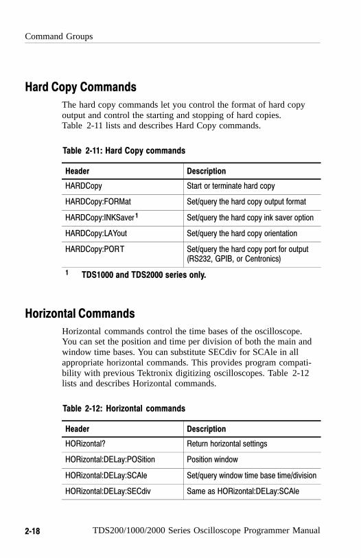
Hard Copy Commands
The hard copy commands let you control the format of hard copyoutput and control the starting and stopping of hard copies. Table 2-11 lists and describes Hard Copy commands.
Table 2−11: Hard Copy commands
Header Description
HARDCopy Start or terminate hard copy
HARDCopy:FORMat Set/query the hard copy output format
HARDCopy:INKSaver 1 Set/query the hard copy ink saver option
HARDCopy:LAYout Set/query the hard copy orientation
HARDCopy:PORT Set/query the hard copy port for output(RS232, GPIB, or Centronics)
1 TDS1000 and TDS2000 series only.
Horizontal Commands
Horizontal commands control the time bases of the oscilloscope. You can set the position and time per division of both the main andwindow time bases. You can substitute SECdiv for SCAle in allappropriate horizontal commands. This provides program compati-bility with previous Tektronix digitizing oscilloscopes. Table 2-12lists and describes Horizontal commands.
Table 2−12: Horizontal commands
Header Description
HORizontal? Return horizontal settings
HORizontal:DELay:POSition Position window
HORizontal:DELay:SCAle Set/query window time base time/division
HORizontal:DELay:SECdiv Same as HORizontal:DELay:SCAle

Command Groups
TDS200/1000/2000 Series Oscilloscope Programmer Manual 2−19
Table 2−12: Horizontal commands (Cont.)
Header Description
HORizontal:MAIn Set/query main time base time/division
HORizontal:MAIn:POSition Set/query main time base trigger point
HORizontal:MAIn:SCAle Set/query main time base time/division
HORizontal:MAIn:SECdiv Same as HORizontal:MAIn:SCAle
HORizontal:POSition Set/query position of waveform to display
HORizontal:RECOrdlength Return waveform record length
HORizontal:SCAle Same as HORizontal:MAIn:SCAle
HORizontal:SECdiv Same as HORizontal:MAIn:SCAle
HORizontal:VIEW Select view
Math Commands
Math commands provide math function definition. Table 2-13 listsand describes Math commands.
Table 2−13: Math commands
Header Description
MATH? Query the definition for the math wave−form
MATH:DEFINE Set/query math waveform definition
MATH:FFT:HORizontal:POSition1 Set/query FFT horizontal display position
MATH:FFT:HORizontal:SCAle1 Set/query FFT horizontal zoom factor
MATH:FFT:VERtical:POSition1 Set/query FFT vertical display position
MATH:FFT:VERtical:SCAle1 Set/query FFT vertical zoom factor
1 TDS1000 and TDS2000 series, or TDS200 series with a TDS2MMmeasurement module.

Command Groups
2−20 TDS200/1000/2000 Series Oscilloscope Programmer Manual
Measurement Commands
Measurement commands control the automated measurementsystem. Up to four (TDS200 series) or five (TDS1000 and TDS2000series) automated measurements can be displayed on the oscillo-scope screen. In the commands, these measurement readouts arenamed MEAS<x>, where <x> can be 1, 2, 3, or 4 (or 5 for TDS1000and TDS2000 series).
The best method for taking measurements over the computerinterface is to use the MEASUREMENT:IMMED commands andqueries. The immediate measurement has no front-panel equivalent,and the oscilloscope never displays immediate measurements.
Because they are computed only when they are requested, immediatemeasurements slow the waveform update rate less than displayedmeasurements.
Use the VALue? query to obtain measurement results of eitherdisplayed or immediate measurements.
Several measurement commands set and query measurementparameters. You can assign some parameters, such as waveformsources, differently for each measurement readout.
Table 2-14 lists and describes Measurement commands.
Table 2−14: Measurement commands
Header Description
MEASUrement? Return all measurement parameters
MEASUrement:IMMed? Return immediate measurement param−eters
MEASUrement:IMMed:SOUrce Set/query channel to take the immediatemeasurement from
MEASUrement:IMMed:TYPe Set/query the immediate measurementto be taken
MEASUrement:IMMed:UNIts? Return the immediate measurementunits

Command Groups
TDS200/1000/2000 Series Oscilloscope Programmer Manual 2−21
Table 2−14: Measurement commands (Cont.)
Header Description
MEASUrement:IMMed:VALue? Return the immediate measurementresult
MEASUrement:MEAS<x>? Return parameters on the periodicmeasurement
MEASUrement:MEAS<x>:SOUrce Set/query channel to take the periodicmeasurement from
MEASUrement:MEAS<x>:TYPe Set/query the type of periodic measure−ment to be taken
MEASUrement:MEAS<x>:UNIts? Returns the units for periodic measure−ment
MEASUrement:MEAS<x>:VALue? Returns periodic measurement results
Miscellaneous Commands
Miscellaneous commands are a group of commands that do not fitinto any other category.
Several commands and queries are common to all 488.2–1987devices on the GPIB BUS and the device on the RS-232 interface.These commands and queries are defined by IEEE Std. 488.2–1987and Tek Standard Codes and Formats 1989 and begin with anasterisk (*) character. Table 2-15 lists and describes Miscellaneouscommands.
Table 2−15: Miscellaneous commands
Header Description
AUTOSet Automatic oscilloscope setup
AUTOSet:SIGNAL?1 Returns the type of signal found byautoset
AUTOSet:VIEW1 Set/query Autoset view
Command Groups
2−22 TDS200/1000/2000 Series Oscilloscope Programmer Manual
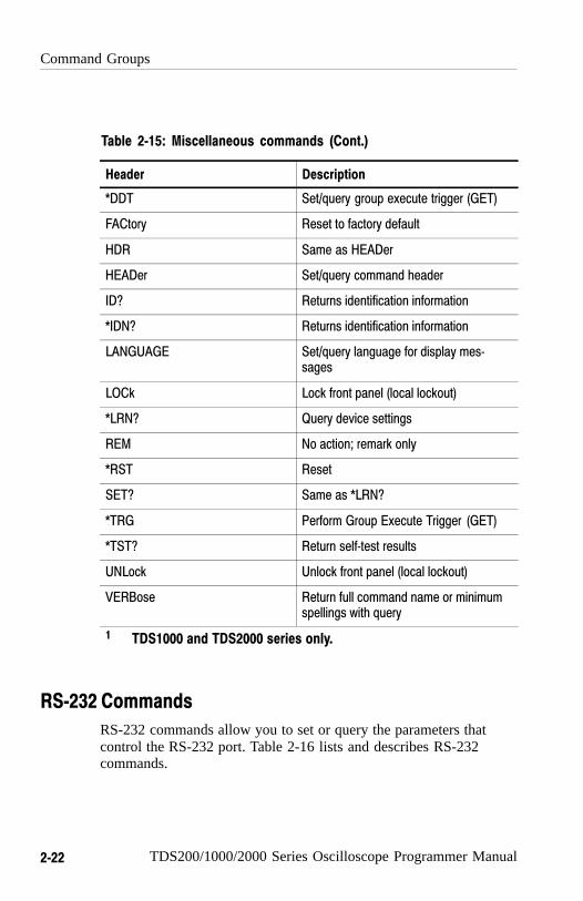
Table 2−15: Miscellaneous commands (Cont.)
Header Description
*DDT Set/query group execute trigger (GET)
FACtory Reset to factory default
HDR Same as HEADer
HEADer Set/query command header
ID? Returns identification information
*IDN? Returns identification information
LANGUAGE Set/query language for display mes−sages
LOCk Lock front panel (local lockout)
*LRN? Query device settings
REM No action; remark only
*RST Reset
SET? Same as *LRN?
*TRG Perform Group Execute Trigger (GET)
*TST? Return self−test results
UNLock Unlock front panel (local lockout)
VERBose Return full command name or minimumspellings with query
1 TDS1000 and TDS2000 series only.
RS−232 Commands
RS-232 commands allow you to set or query the parameters thatcontrol the RS-232 port. Table 2-16 lists and describes RS-232commands.
Command Groups
TDS200/1000/2000 Series Oscilloscope Programmer Manual 2−23
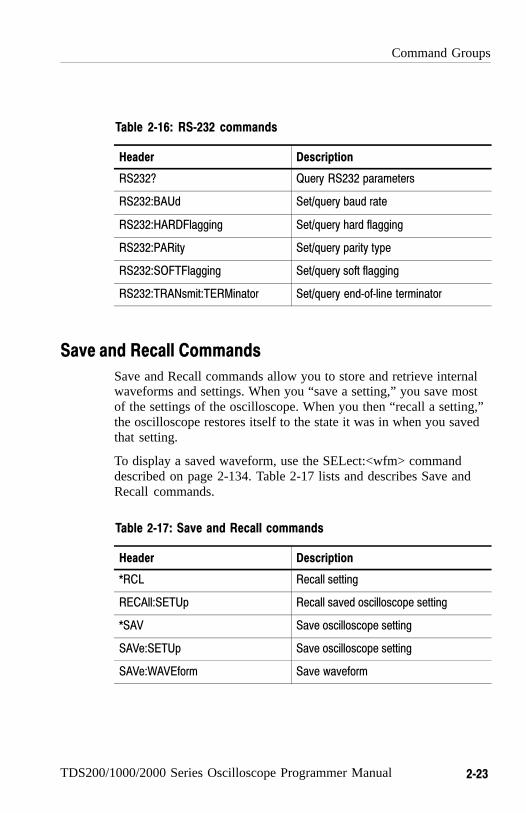
Table 2−16: RS−232 commands
Header Description
RS232? Query RS232 parameters
RS232:BAUd Set/query baud rate
RS232:HARDFlagging Set/query hard flagging
RS232:PARity Set/query parity type
RS232:SOFTFlagging Set/query soft flagging
RS232:TRANsmit:TERMinator Set/query end−of−line terminator
Save and Recall Commands
Save and Recall commands allow you to store and retrieve internalwaveforms and settings. When you “save a setting,” you save mostof the settings of the oscilloscope. When you then “recall a setting,”the oscilloscope restores itself to the state it was in when you savedthat setting.
To display a saved waveform, use the SELect:<wfm> commanddescribed on page 2-134. Table 2-17 lists and describes Save andRecall commands.
Table 2−17: Save and Recall commands
Header Description
*RCL Recall setting
RECAll:SETUp Recall saved oscilloscope setting
*SAV Save oscilloscope setting
SAVe:SETUp Save oscilloscope setting
SAVe:WAVEform Save waveform

Command Groups
2−24 TDS200/1000/2000 Series Oscilloscope Programmer Manual
Status and Error Commands
Status and error commands let you determine the status of theoscilloscope and control events.
Several commands and queries are common to all devices on theGPIB bus. These commands and queries are defined by IEEE Std.488.2–1987 and Tek Standard Codes and Formats 1989, and beginwith an asterisk (*) character. Table 2-18 lists and describes Statusand Error commands.
Table 2−18: Status and Error commands
Header Description
ALLEv? Return all events
BUSY? Return oscilloscope busy status
*CLS Clear status
DESE Set/query device event status enable
*ESE Set/query standard event status enable
*ESR? Return standard event status register; this is the usualway to determine whether a set command executedwithout error
EVENT? Return event code
EVMsg? Return event message
EVQty? Return number of events in queue
*OPC Set/query operation complete
*PSC Set/query power−on status clear
*SRE Set/query service request enable
*STB? Read status byte
*WAI Wait to continue

Command Groups
TDS200/1000/2000 Series Oscilloscope Programmer Manual 2−25
Trigger Commands
Trigger commands control all aspects of oscilloscope triggering.
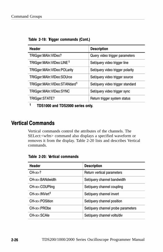
The two types of triggers are edge and video. Edge triggering is thedefault type. Edge triggering lets you acquire a waveform when thesignal passes through a voltage level of your choosing. Videotriggering adds the capability of triggering on video fields and lines.Table 2-19 lists and describes Trigger commands.
Table 2−19: Trigger commands
Header Description
TRIGger Force trigger event
TRIGger:MAIn Set main trigger level to 50%; Queryreturns main trigger settings
TRIGger:MAIn:EDGE? Return edge trigger settings
TRIGger:MAIn:EDGE:COUPling Set/query edge trigger coupling
TRIGger:MAIn:EDGE:SLOpe Set/query edge trigger slope
TRIGger:MAIn:EDGE:SOUrce Set/query edge trigger source
TRIGger:MAIn:FREQuency?1 Return trigger frequency value
TRIGger:MAIn:HOLDOf f? Return trigger holdoff value
TRIGger:MAIn:HOLDOf f:VALue Set/query trigger holdoff value
TRIGger:MAIn:LEVel Set/query trigger level
TRIGger:MAIn:MODe Set/query trigger mode
TRIGger:MAIn:TYPe Set/query main trigger type
TRIGger:MAIn:PULse?1 Return pulse trigger settings
TRIGger:MAIn:PULse:SOUrce 1 Set/query pulse trigger source
TRIGger:MAIn:PULse:WIDth:POLarity 1 Set/query pulse trigger polarity
TRIGger:MAIn:PULse:WIDth:WHEN 1 Set/query pulse trigger when
TRIGger:MAIn:PULse:WIDth:WIDth 1 Set/query pulse trigger width
Command Groups
2−26 TDS200/1000/2000 Series Oscilloscope Programmer Manual
Table 2−19: Trigger commands (Cont.)
Header Description
TRIGger:MAIn:VIDeo? Query video trigger parameters
TRIGger:MAIn:VIDeo:LINE 1 Set/query video trigger line
TRIGger:MAIn:VIDeo:POLarity Set/query video trigger polarity
TRIGger:MAIn:VIDeo:SOUrce Set/query video trigger source
TRIGger:MAIn:VIDeo:STANdard1 Set/query video trigger standard
TRIGger:MAIn:VIDeo:SYNC Set/query video trigger sync
TRIGger:STATE? Return trigger system status
1 TDS1000 and TDS2000 series only.
Vertical Commands
Vertical commands control the attributes of the channels. TheSELect:<wfm> command also displays a specified waveform orremoves it from the display. Table 2-20 lists and describes Verticalcommands.
Table 2−20: Vertical commands
Header Description
CH<x>? Return vertical parameters
CH<x>:BANdwidth Set/query channel bandwidth
CH<x>:COUPling Set/query channel coupling
CH<x>:INVert1 Set/query channel invert
CH<x>:POSition Set/query channel position
CH<x>:PRObe Set/query channel probe parameters
CH<x>:SCAle Set/query channel volts/div
Command Groups
TDS200/1000/2000 Series Oscilloscope Programmer Manual 2−27
Table 2−20: Vertical commands (Cont.)
Header Description
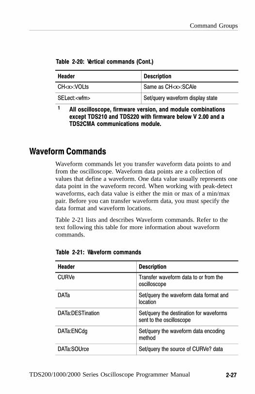
CH<x>:VOLts Same as CH<x>:SCAle
SELect:<wfm> Set/query waveform display state
1 All oscilloscope, firmware version, and module combinationsexcept TDS210 and TDS220 with firmware below V 2.00 and aTDS2CMA communications module.
Waveform Commands
Waveform commands let you transfer waveform data points to andfrom the oscilloscope. Waveform data points are a collection ofvalues that define a waveform. One data value usually represents onedata point in the waveform record. When working with peak-detectwaveforms, each data value is either the min or max of a min/maxpair. Before you can transfer waveform data, you must specify thedata format and waveform locations.
Table 2-21 lists and describes Waveform commands. Refer to thetext following this table for more information about waveformcommands.
Table 2−21: Waveform commands
Header Description
CURVe Transfer waveform data to or from theoscilloscope
DATa Set/query the waveform data format andlocation
DATa:DESTination Set/query the destination for waveformssent to the oscilloscope
DATa:ENCdg Set/query the waveform data encodingmethod
DATa:SOUrce Set/query the source of CURVe? data
Command Groups
2−28 TDS200/1000/2000 Series Oscilloscope Programmer Manual
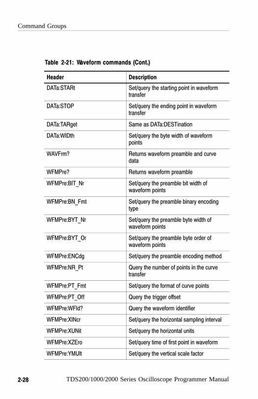
Table 2−21: Waveform commands (Cont.)
Header Description
DATa:STARt Set/query the starting point in waveformtransfer
DATa:STOP Set/query the ending point in waveformtransfer
DATa:TARget Same as DATa:DESTination
DATa:WIDth Set/query the byte width of waveformpoints
WAVFrm? Returns waveform preamble and curvedata
WFMPre? Returns waveform preamble
WFMPre:BIT_Nr Set/query the preamble bit width ofwaveform points
WFMPre:BN_Fmt Set/query the preamble binary encodingtype
WFMPre:BYT_Nr Set/query the preamble byte width ofwaveform points
WFMPre:BYT_Or Set/query the preamble byte order ofwaveform points
WFMPre:ENCdg Set/query the preamble encoding method
WFMPre:NR_Pt Query the number of points in the curvetransfer
WFMPre:PT_Fmt Set/query the format of curve points
WFMPre:PT_Off Query the trigger offset
WFMPre:WFId? Query the waveform identifier
WFMPre:XINcr Set/query the horizontal sampling interval
WFMPre:XUNit Set/query the horizontal units
WFMPre:XZEro Set/query time of first point in waveform
WFMPre:YMUlt Set/query the vertical scale factor

Command Groups
TDS200/1000/2000 Series Oscilloscope Programmer Manual 2−29
Table 2−21: Waveform commands (Cont.)
Header Description
WFMPre:YOFf Set/query the vertical offset
WFMPre:YUNit Set/query the vertical units
WFMPre:YZEro?1 Set/query the waveform conversion factor
WFMPre:<wfm>? Returns waveform formatting data
WFMPre:<wfm>:PT_Fmt Set/query the format of curve points
WFMPre:<wfm>:PT_Off? Query the trigger offset
WFMPre:<wfm>:WFId? Query the waveform identifier
WFMPre:<wfm>:XINcr Set/query the horizontal sampling interval
WFMPre:<wfm>:XUNit Set/query the horizontal units
WFMPre:<wfm>:XZEro Set/query the time of first datapoint inwaveform
WFMPre:<wfm>:YMUlt Set/query the vertical scale factor
WFMPre:<wfm>:YOFf Set/query the vertical position
WFMPre:<wfm>:YUNit Set/query the vertical units
WFMPre:<wfm>:YZEro? 1 Set/query the waveform conversion factor
1 TDS1000 and TDS2000 series, or TDS200 series with a TDS2MMmeasurement module.
Waveform Data Formats
Internally, the oscilloscope uses one 8-bit data byte to represent eachwaveform data point, regardless of the acquisition mode.
The DATa:WIDth command lets you specify the number of bytes perdata point when transferring data to and from an oscilloscope. Thisprovides compatibility with other digitizing oscilloscopes.

Command Groups
2−30 TDS200/1000/2000 Series Oscilloscope Programmer Manual
When DATa:WIDth is set to two:
� If sending data, the oscilloscope mulitplies each point by 256; themost significant byte then has meaningful data and the leastsignificant byte is 0
� If receiving data, the oscilloscope truncates the data (divides by256) and saves the most significant byte
NOTE. The oscilloscopes uses these methods to handle waveformstransmitted in ASCII or binary format.
The oscilloscope can transfer waveform data in either ASCII orbinary format. Use the DATa:ENCdg command to specify one of thefollowing formats:
� ASCII data is represented by signed integer values. The range ofvalues depends on the byte width specified. One-byte-wide dataranges from –128 to 127. Two-byte-wide data ranges from–32768 to 32767.
Each data value requires two to seven characters. This includesone character for the minus sign if the value is negative, one tofive ASCII characters for the waveform value, and a comma toseparate data points.
An example of an ASCII waveform data string follows:
CURVE<space>–110,–109,–110,–110,–109,–107,–109,–107,–106,–105,–103,–100,–97,–90,–84,–80
� Binary data can be represented by signed integer or positiveinteger values. The range of the values depends on the byte widthspecified.
Table 2-22 lists the ranges for one- and two-byte-wide data.
Command Groups
TDS200/1000/2000 Series Oscilloscope Programmer Manual 2−31
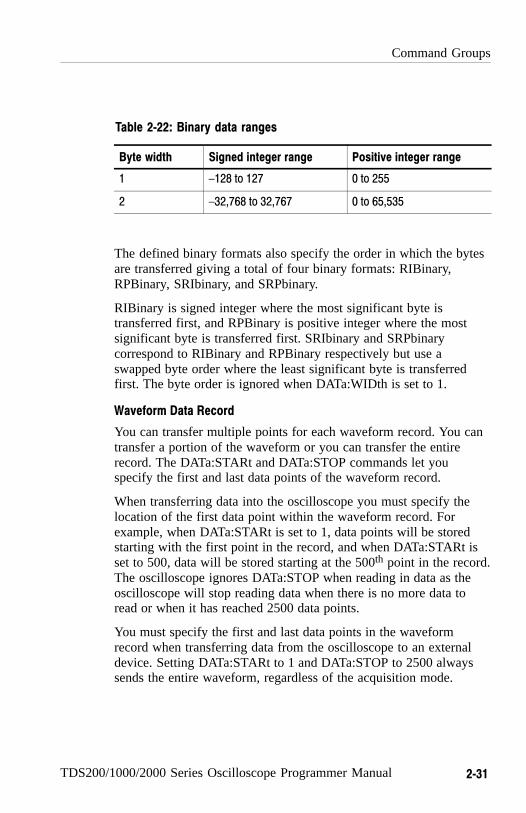
Table 2−22: Binary data ranges
Byte width Signed integer range Positive integer range
1 –128 to 127 0 to 255
2 –32,768 to 32,767 0 to 65,535
The defined binary formats also specify the order in which the bytesare transferred giving a total of four binary formats: RIBinary,RPBinary, SRIbinary, and SRPbinary.
RIBinary is signed integer where the most significant byte istransferred first, and RPBinary is positive integer where the mostsignificant byte is transferred first. SRIbinary and SRPbinarycorrespond to RIBinary and RPBinary respectively but use aswapped byte order where the least significant byte is transferredfirst. The byte order is ignored when DATa:WIDth is set to 1.
Waveform Data Record
You can transfer multiple points for each waveform record. You cantransfer a portion of the waveform or you can transfer the entirerecord. The DATa:STARt and DATa:STOP commands let youspecify the first and last data points of the waveform record.
When transferring data into the oscilloscope you must specify thelocation of the first data point within the waveform record. Forexample, when DATa:STARt is set to 1, data points will be storedstarting with the first point in the record, and when DATa:STARt isset to 500, data will be stored starting at the 500th point in the record.The oscilloscope ignores DATa:STOP when reading in data as theoscilloscope will stop reading data when there is no more data toread or when it has reached 2500 data points.
You must specify the first and last data points in the waveformrecord when transferring data from the oscilloscope to an externaldevice. Setting DATa:STARt to 1 and DATa:STOP to 2500 alwayssends the entire waveform, regardless of the acquisition mode.

Command Groups
2−32 TDS200/1000/2000 Series Oscilloscope Programmer Manual
Waveform Data Locations and Memory Allocation
The DATa:SOUrce command specifies the location of the data whentransferring waveforms from the oscilloscope. You can transfer onewaveform at a time.
You can transfer only one waveform into the oscilloscope at a time.Each waveform is stored in one of two stored waveform locations for2-channel models or one of four stored waveform locations for4-channel models. You specify the stored waveform location withthe DATa:DESTination command.
NOTE. The oscilloscope stores waveforms that are �2500 data pointslong. The oscilloscope truncates waveforms longer than 2500 datapoints.
Waveform Preamble
Each waveform that is transferred has an associated waveformpreamble that contains information such as the horizontal scale,vertical scale, and other settings in place when the waveform wascreated. Refer to the WFMPre commands on page 2-158 for moreinformation about the waveform preamble.
Scaling Waveform Data
Once you transfer the waveform data to the controller, you canconvert the data points into voltage values for analysis usinginformation from the waveform preamble.
Transferring Waveform Data
Data transfer times depend on data format, data width, and the speedof the controller. Refer to Programming Examples on page 4-1.
From the Oscilloscope. To transfer waveforms from the oscilloscope toan external controller, follow these steps:
1. Use the DATa:SOUrce command to select the waveform source.
2. Use the DATa:ENCdg command to specify the waveform dataformat.

Command Groups
TDS200/1000/2000 Series Oscilloscope Programmer Manual 2−33
3. Use the DATa:WIDth command to specify the number of bytesper data point.
4. Use the DATa:STARt and DATa:STOP commands to specify theportion of the waveform that you want to transfer.
5. Use the WFMPRe? command to transfer waveform preambleinformation.
6. Use the CURVe? command to transfer waveform data.
To the Oscilloscope. To transfer waveform data to an oscilloscopewaveform storage location, follow these steps:
1. Use the DATa:DESTination command to specify the storedwaveform location.
2. Use the DATa:ENCdg command to specify the waveform dataformat.
3. Use the DATa:WIDth command to specify the number of bytesper data point.
4. Use the DATa:STARt command to specify the first data point inthe waveform record.
5. Use the WFMPRe command to transfer waveform preambleinformation.
6. Use the CURVe? command to transfer waveform data.

Command Groups
2−34 TDS200/1000/2000 Series Oscilloscope Programmer Manual

TDS200/1000/2000 Series Oscilloscope Programmer Manual 2−35
Command Descriptions
Commands either set or query oscilloscope values. Some commandsboth set and query, some only set, and some only query.
Manual Conventions
This manual uses the following conventions:
� No Query Form indicates set-only commands
� A question mark (?) appended to the command and Query Onlyindicates query-only commands
� Fully spells out headers, mnemonics, and arguments with theminimal spelling shown in upper case; for example, to use theabbreviated form of the ACQuire:MODe command, just typeACQ:MOD
� Syntax of some commands varies, depending on the model ofoscilloscope and extension module you are using; differences arenoted
NOTE. While Trigger View is active (when you push the TRIG VIEWbutton on the front panel), the oscilloscope ignores the set form ofmost commands. If you send a command at this time, the oscilloscopegenerates execution error 221 (Settings conflict).
ACQuire? (Query Only)
Returns all the current acquisition parameters.
Acquistion
ACQuire?
Group
Syntax
Command Descriptions
2−36 TDS200/1000/2000 Series Oscilloscope Programmer Manual
Returns current acquisition parameters.
ACQuire?might return the string :ACQUIRE:STOPAFTER RUNSTOP;STATE1;MODE SAMPLE;NUMAVG 16 for the current acquisition parameters.
ACQuire:MODe
Sets or queries the oscilloscope acquisition mode. This affects alllive waveforms and is equivalent to setting the Mode option in theAcquire menu.
Waveforms are the displayed data point values taken fromacquisition intervals. Each acquisition interval represents a timeduration that is determined by the horizontal scale (time perdivision).
The oscilloscope sampling system can operate at a rate greater thanthat indicated by the horizontal scale. Therefore, an acquisitioninterval can include more than one sample.
The acquisition mode, which you set using this ACQuire:MODecommand, determines how the final value of the acquisition intervalis generated from the many data samples.
Acquisition
ACQuire:MODe { SAMple | PEAKdetect | AVErage }
ACQuire:MODe?
SAMple specifies that the displayed data point value is the firstsampled value that was taken during the acquisition interval. Thewaveform data has 8 bits of precision in all acquisition modes. Youcan request 16 bit data with a CURVe? query, but the lower-order8 bits of data will be zero. SAMple is the default mode.
Returns
Examples
Group
Syntax
Arguments

Command Descriptions
TDS200/1000/2000 Series Oscilloscope Programmer Manual 2−37
PEAKdetect specifies the display of the high-low range of thesamples taken from a single waveform acquisition. The oscilloscopedisplays the high-low range as a vertical range that extends from thehighest to the lowest value sampled during the acquisition interval.PEAKdetect mode can reveal the presence of aliasing.
AVErage specifies averaging mode, where the resulting waveformshows an average of SAMple data points from several separatewaveform acquisitions. The number of waveform acquisitions thatgo into making up the average waveform is set or queried using theACQuire:NUMAVg command.
ACQuire:MODe PEAKdetect displays a vertical area representing the range of the highest tolowest value of the acquired signal.
ACQuire:MODe?might return SAMPLE
WFMPre:PT_Fmt
ACQuire:NUMACq? (Query Only)
Indicates the number of acquisitions that have taken place sincestarting oscilloscope acquisition. The maximum number ofacquisitions that can be counted is 231-1. This value is reset to zerowhen you change most Acquisition, Horizontal, Vertical, or Triggerarguments that affect the waveform except for the following:
� Changing the trigger level or trigger holdoff when in Sample orPeak Detect mode does not reset the value
NOTE. Any change made when in Average mode aborts theacquisition and resets ACQuire:NUMACq to zero.
� TDS200 series: changing the vertical position does not reset thevalue
Examples
Related Commands

Command Descriptions
2−38 TDS200/1000/2000 Series Oscilloscope Programmer Manual
� TDS1000 and TDS2000 series: if the Trigger mode is set to Auto,and the Horizontal Scale is 10 ms/div or slower, changing thevertical position does not reset the value
NOTE. In Scan mode, ACQuire:NUMACq? always returns zero.
Acquisition
ACQuire:NUMACq?
<NR1>
ACQuire:NUMACq?might return 350, indicating that 350 acquisitions took place since anACQuire:STATE RUN command was executed.
ACQuire:NUMAVg
Sets the number of oscilloscope waveform acquisitions that make upan averaged waveform. This command is equivalent to setting theAverages option in the Acquire menu.
Acquisition
ACQuire:NUMAVg <NR1>
ACQuire:NUMAVg?
Group
Syntax
Returns
Examples
Group
Syntax

Command Descriptions
TDS200/1000/2000 Series Oscilloscope Programmer Manual 2−39
<NR1> is the number of waveform acquisitions. Correct values are 4,16, 64, and 128.
ACQuire:NUMAVg 16specifies that an averaged waveform will show the result ofcombining 16 separately acquired waveforms.
ACQuire:NUMAVg?might return 64, indicating that there are 64 acquisitions specifiedfor averaging.
ACQuire:STATE
Starts or stops oscilloscope acquisitions. This command is theequivalent of pressing the front-panel RUN/STOP button. IfACQuire:STOPAfter is set to SEQuence, other signal events mayalso stop acquisition.
NOTE. The best way to determine when a single sequence acquisitionis complete is to use *OPC? rather than ACQuire:STATE?. For moreinformation on the *OPC? command, refer to page 2-121.
Acquisition
ACQuire:STATE { OFF | ON | RUN | STOP | <NR1> }
ACQuire:STATE?
OFF | STOP | <NR1> = 0 stops acquisitions.
Arguments
Examples
Group
Syntax
Arguments
Command Descriptions
2−40 TDS200/1000/2000 Series Oscilloscope Programmer Manual
ON | RUN | <NR1> ≠ 0 starts acquisition and display of waveforms. Ifthe command was issued in the middle of an acquisition sequence(for instance averaging), RUN restarts the sequence, discarding anydata accumulated before the STOP. It also resets the number ofacquisitions.
ACQuire:STATE RUN starts acquisition of waveform data and resets the number ofacquisitions count (NUMACq) to zero.
ACQuire:STATE? returns 0 or 1, depending on whether or not the acquisition system isrunning.
*OPC?
ACQuire:STOPAfter
Tells the oscilloscope when to stop taking acquisitions.
Acquisition
ACQuire:STOPAfter { RUNSTop | SEQuence}
ACQuire:STOPAfter?
RUNSTop specifies that the run and stop states should be determinedby pressing the front-panel RUN/STOP button or issuing theACQuire:STATE command.
Examples
Related Commands
Group
Syntax
Arguments
Command Descriptions
TDS200/1000/2000 Series Oscilloscope Programmer Manual 2−41
SEQuence specifies “single sequence” operation, where theoscilloscope stops after it has acquired enough waveforms to satisfythe conditions of the acquisition mode. For example, if theacquisition mode is set to sample, the oscilloscope stops afterdigitizing a waveform from a single trigger event. However, if theacquisition mode is set to average 64 waveforms, then the oscillo-scope stops only after acquiring all 64 waveforms.
The ACQuire:STATE command and the front-panel RUN/STOPbutton also stop acquisitions when the oscilloscope is in singlesequence mode.
ACQuire:STOPAfter RUNSTop sets the oscilloscope to stop the acquisition when you press thefront-panel RUN/STOP button.
ACQuire:STOPAfter? might return SEQUENCE
ALLEv? (Query Only)
Causes the oscilloscope to return all events and their messages, andremoves the returned events from the Event Queue. The messagesare separated by commas. Use the *ESR? query to enable the eventsto be returned. For a complete discussion of how to use theseregisters, refer to page 3-1. This command is similar to repeatedlysending *EVMsg? queries to the oscilloscope.
Status and error
ALLEv?
The event code and message in the following format:
Examples
Group
Syntax
Returns

Command Descriptions
2−42 TDS200/1000/2000 Series Oscilloscope Programmer Manual
<Event Code><Comma><QString>[<Comma><EventCode><Comma><QString>...]
<QString>::= <Message>;[<Command>]
<Command> is the command that caused the error and may bereturned when a command error is detected by the oscilloscope. Asmuch of the command is returned as possible without exceeding the60 character limit of the <Message> and <Command> stringscombined. The command string is right-justified.
ALLEv?might return the string :ALLEV 2225,NMeasurement error, Nowaveform to measure; ",420,NQuery UNTERMINATED; "
*CLS, DESE, *ESE, *ESR?, EVENT?, EVMsg?, EVQty?, *SRE,*STB?
AUTOSet (No Query Form)
Causes the oscilloscope to adjust its vertical, horizontal, and triggercontrols to display a stable waveform. This command is equivalentto pushing the front-panel AUTOSET button.
For a detailed description of the Autoset function, refer to the usermanual for your oscilloscope.
Miscellaneous
AUTOSet EXECute
EXECute invokes Autoset.
Examples
Related Commands
Group
Syntax
Arguments
Command Descriptions
TDS200/1000/2000 Series Oscilloscope Programmer Manual 2−43
AUTOSet:SIGNAL? (Query Only)
NOTE. You can use this command ONLY with the TDS1000 andTDS2000 series.
Returns the type of signal discovered by the most recent execution ofAutoset.
Miscellaneous
AUTOSet:SIGNAL?
{ LEVEL | SINE | SQUARE | VIDPAL | VIDNTSC | OTHER |NONE }
LEVELThe oscilloscope discovered a DC level.
SINEThe oscilloscope discovered a sine-like waveform.
SQUAREThe oscilloscope discovered a square-like waveform.
VIDPALThe oscilloscope discovered a PAL or SECAM standard videosignal.
VIDNTSCThe oscilloscope discovered an NTSC standard video signal.
OTHERThe oscilloscope was unable to classify the signal.
NONEThe AUTOSET menu is not displayed.
Group
Syntax
Returns

Command Descriptions
2−44 TDS200/1000/2000 Series Oscilloscope Programmer Manual
AUTOSet:VIEW
NOTE. You can use this command ONLY with the TDS1000 andTDS2000 series.
Sets and queries the current view.
If the current menu is not the Autoset menu, or if the view is notvalid for the detected waveform, the set command causes theoscilloscope to generate error 221 (Settings conflict).
Miscellaneous
AUTOSet:VIEW { MULTICYcle | SINGLECYcle | FFT |RISINGedge | FALLINGedge | FIELD | ODD | EVEN | LINE |LINENum | DCLIne | DEFault | NONE }
MULTICYcleSine or square display of several cycles. Default for sine-like andsquare-like signals.
SINGLECYcleSine or square display of approximately one cycle.
FFTFFT of a sine wave.
RISINGedgeDisplay of the rising edge of a square wave.
FALLINGedgeDisplay of the falling edge of a square wave.
FIELDVideo signal display that is synced on all fields. Default for videosignals.
Group
Syntax
Arguments

Command Descriptions
TDS200/1000/2000 Series Oscilloscope Programmer Manual 2−45
ODD Video signal display that is synced on odd fields.
EVEN Video signal display that is synced on even fields.
LINE Video signal display synced on all lines.
LINENum Video signal display synced on the specified line number.
DCLIne Query response when the oscilloscope found a DC level.
DEFault Query response when the oscilloscope could not determine the signaltype.
NONE Query response when the AUTOSET menu is not displayed. Set isignored.
BUSY? (Query Only)
Returns the status of the oscilloscope. This command allows you tosynchronize the operation of the oscilloscope with your applicationprogram. Refer to Synchronization Methods on page 3-10 for moreinformation.
Status and error
BUSY?
0 means that the oscilloscope is not busy processing any of thecommands listed in Table 2-25 (*OPC) on page 2-121.
1 means that the oscilloscope is busy processing one of thecommands listed in Table 2-25 (*OPC) on page 2-121.
Group
Syntax
Returns

Command Descriptions
2−46 TDS200/1000/2000 Series Oscilloscope Programmer Manual
BUSY?might return 1, indicating that the oscilloscope is busy.
*OPC, *WAI
*CAL? (Query Only)
Performs an internal self-calibration and returns its status. This isequivalent to selecting the Do Self Cal option in the Utility menu.Although *CAL? is a query command, it does perform an action.
NOTE. The self-calibration can take several minutes to complete.During this time, the oscilloscope does not execute any commands.
Disconnect all signals from the oscilloscope before performing aninternal self-calibration.
Calibration and Diagnostic
*CAL?
0 indicates that the self-calibration completed without any errorsdetected.
Any value other than zero indicates that the self-calibration did notcomplete successfully or completed with errors.
*CAL?performs a self-calibration and might return 0 to indicate that itcompleted successfully.
Examples
Related Commands
Group
Syntax
Returns
Examples
Command Descriptions
TDS200/1000/2000 Series Oscilloscope Programmer Manual 2−47
CALibrate:INTERNAL
CALibrate:ABOrt (No Query Form)
NOTE. You should only use this command in a qualified serviceenvironment. For more information about the factory calibrationsequence, refer to the sevice manual for your oscilloscope.
Aborts the factory calibration process. When you abort the factorycalibration, the oscilloscope restores the calibration settings to theprevious factory calibration constants stored in non-volatile memory.
Calibration and Diagnostic
CALibrate:ABOrt
CALibrate:ABOrtstops the in-process factory calibration procedure.
CALibrate:CONTINUE (No Query Form)
NOTE. You should only use this command in a qualified serviceenvironment. For more information about the factory calibrationsequence, refer to the sevice manual for your oscilloscope.
Performs the next step in the factory calibration operation.
Calibration and Diagnostic
Related Commands
Group
Syntax
Examples
Group

Command Descriptions
2−48 TDS200/1000/2000 Series Oscilloscope Programmer Manual
CALibrate:CONTINUE
CALibrate:CONTINUEperforms the next step in the factory calibration operation.
CALibrate:FACtory (No Query Form)
NOTE. You should only use this command in a qualified serviceenvironment. For more information about the factory calibrationsequence, refer to the service manual for your oscilloscope.
Starts the oscilloscope’s internal factory calibration operation. Thecalibration operation consists of a sequence of steps. You send theCALibrate:CONTINUE command to advance to the next calibrationstep. The calibration program automatically sets up the oscilloscopefor each calibration step. Use the CALibrate:ABOrt command toabort the factory calibration.
You can only send synchronization commands or queries (such as*OPC, OPC?, *WAI, BUSY?) while doing a factory calibration.
Calibration and Diagnostic
CALibrate:FACtory
CALibrate:FACtorystarts the factory calibration process.
Syntax
Examples
Group
Syntax
Examples
Command Descriptions
TDS200/1000/2000 Series Oscilloscope Programmer Manual 2−49
CALibrate:INTERNAL (No Query Form)
Performs an internal self-calibration but does not return any status.This is equivalent to selecting the Do Self Cal option in the Utilitymenu.
NOTE. The self-calibration can take several minutes to complete.During this time, the oscilloscope does not execute any commands.
Disconnect all signals from the oscilloscope before performing aninternal self-calibration.
CALibrate:INTERNAL
CALibrate:INTERNALperforms an internal self-calibration.
*CAL?
CALibrate:STATUS? (Query Only)
Returns the status of the last calibration operation performed (eitherself- or factory-calibration) since power up.
Calibration and Diagnostic
CALibrate:STATUS?
PASS indicates that the oscilloscope completed the last calibrationoperation without detecting any errors.
Syntax
Examples
Related Commands
Group
Syntax
Returns
Command Descriptions
2−50 TDS200/1000/2000 Series Oscilloscope Programmer Manual
FAIL indicates that the oscilloscope detected errors during the lastcalibration operation, or that no calibration operations have beenperformed since power up.
CALibrate:STATUS?might return CALIBRATE:STATUS FAIL if the oscilloscope failed thelast calibration operation.
CH<x>? (Query Only)
Returns the oscilloscope vertical parameters. Because CH<x>:SCAleand CH<x>:VOLts are identical, only CH<x>:SCAle is returned.
Vertical
CH<x>?
Oscilloscope vertical parameters
CH1?might return the string :CH1:SCALE 1.0E0;POSITION 0.0E0;COUPLING DC;BANDWIDTH OFF;PROBE 1.0E0 for channel 1.
SELect:CH<x>
CH<x>:BANdwidth
Sets or queries the bandwidth setting of the specified oscilloscopechannel. This command is equivalent to setting the BW Limit optionin the Vertical menu.
Examples
Group
Syntax
Returns
Examples
Related Commands

Command Descriptions
TDS200/1000/2000 Series Oscilloscope Programmer Manual 2−51
Vertical
CH<x>:BANdwidth { ON | OFF }
CH<x>:BANdwidth?
ON sets the channel bandwidth to 20 MHz.
OFF sets the channel bandwidth to the full bandwidth of theoscilloscope.
In most acquisition modes, full bandwidth is 60 MHz, 100 MHz, or200 MHz (depending on the oscilloscope model). There areexceptions.
TDS1000 and TDS2000 Series
At vertical scales from 2.00 to 4.99 mV/div (sensitivity at the BNC;that is, after the probe factor is removed), the full bandwidth is 20 MHz.
TDS200 Series
At vertical scales of 5 mV/div or less (sensitivity at the BNC; that is,after the probe factor is removed), the full bandwidth is 20 MHz.When the acquisition mode is Peak Detect, and the vertical scale atthe BNC is 10 mV/div or less, the full bandwidth is also 20 MHz.
CH2:BANDWIDth ONsets the bandwidth of channel 2 to 20 MHz.
CH1:BANDWIDth?might return OFF, which indicates that there is no bandwidthlimiting on channel 1.
Group
Syntax
Arguments
Examples
Command Descriptions
2−52 TDS200/1000/2000 Series Oscilloscope Programmer Manual
CH<x>:COUPling
Sets or queries the input attenuator coupling setting of the specifiedoscilloscope channel. This command is equivalent to setting theCoupling option in the Vertical menu.
Vertical
CH<x>:COUPling { AC | DC | GND }
CH<x>:COUPling?
AC sets the specified oscilloscope channel to AC coupling.
DC sets the specified oscilloscope channel to DC coupling.
GND sets the specified oscilloscope channel to ground. Only a flatground-level waveform is displayed.
CH1:COUPlING ACestablishes AC coupling on channel 1.
CH2:COUPlING?might return DC, indicating that channel 2 is set to DC coupling.
CH<x>:INVert
NOTE. You can NOT use this command with a TDS210 or TDS220oscilloscope with firmware below V 2.00 and a TDS2CMA (orTDS2CM) communications module.
Sets or queries the inversion state of the specified oscilloscopechannel. This command is equivalent to setting the Invert option inthe Vertical channel menus.
Group
Syntax
Arguments
Examples
Command Descriptions
TDS200/1000/2000 Series Oscilloscope Programmer Manual 2−53
Vertical
CH<x>:INVert { ON | OFF }
CH<x>:INVert?
ON inverts the specified oscilloscope channel.
OFF sets the specified oscilloscope channel to non-inverted.
CH1:INVert ONinverts the signal on channel 1.
CH2:INVert?might return OFF, indicating that channel 2 is not inverted.
CH<x>:POSition
Sets or queries the vertical position of the specified oscilloscopechannel. The position voltage value is applied to the signal beforedigitization. This command is equivalent to adjusting the front-panelVERTICAL POSITION knob.
Vertical
CH<x>:POSition <NR3>
CH<x>:POSition?
<NR3> is the position in divisions from the center graticule. Table 2-23 lists the vertical position ranges using a 1X probe.
Group
Syntax
Arguments
Examples
Group
Syntax
Arguments

Command Descriptions
2−54 TDS200/1000/2000 Series Oscilloscope Programmer Manual
Table 2−23: Vertical position ranges using a 1X probe
CH<x>:SCAle Position range
2 mV/div ±1000 divs
5 mV/div ±400 divs
10 mV/div ±400 divs
20 mV/div ±400 divs
50 mV/div ±400 divs
100 mV/div ±400 divs
200 mV/div ±10 divs
500 mV/div ±100 divs
1 V/div ±100 divs
2 V/div ±100 divs
5 V/div ±10 divs
CH2:POSition 1.32E0positions the channel 2 input signal 1.32 divisions above the centerof the display.
CH1:POSition?might return –1.32E0, indicating that the current position of channel1 is at –1.32 divisions.
CH<x>:PRObe
Sets or queries the attenuation factor of the specified channel.
Vertical
CH<x>:PRObe { 1 | 10 | 100 | 1000 }
Examples
Group
Syntax
Command Descriptions
TDS200/1000/2000 Series Oscilloscope Programmer Manual 2−55
CH<x>:PRObe?
1 sets the specified oscilloscope channel to 1X attenuation.
10 sets the specified oscilloscope channel to 10X attenuation.
100 sets the specified oscilloscope channel to 100X attenuation.
1000 sets the specified oscilloscope channel to 1000X attenuation.
<NR1>
CH2:PRObe 1000sets channel 2 to x1000 attenuation.
CH1:PRObe?might return CH1:PROBE 10
CH<x>:SCAle
Sets or queries the vertical gain of the specified oscilloscopechannel. This command is equivalent to adjusting the front-panelVOLTS/DIV knob.
Vertical
CH<x>:SCAle <NR3>
CH<x>:SCAle?
<NR3> is the gain, in volts per division. The range is 5 V/div to2 mV/div when using a 1X probe.
Arguments
Returns
Examples
Group
Syntax
Arguments

Command Descriptions
2−56 TDS200/1000/2000 Series Oscilloscope Programmer Manual
CH1:SCAle 100E–3sets the channel 1 gain to 100 mV/div.
CH2:SCAle?might return 1.0E0, indicating that the current V/div setting ofchannel 2 is 1 V/div.
CH1:VOLts
CH<x>:VOLts
Sets or queries the vertical gain of the specified channel. Thiscommand is identical to the CH<x>:SCAle command and isincluded for compatibility purposes. Only CH<x>:SCAle is returnedin response to a CH<x>? query.
*CLS (No Query Form)
The *CLS command clears the following oscilloscope status datastructures:
� The Event Queue
� The Standard Event Status Register (SESR)
� The Status Byte Register (except the MAV bit described on page2-56)
If the *CLS command immediately follows an <EOI>, the OutputQueue and MAV bit (Status Byte Register bit 4) are also cleared.MAV indicates information is in the output queue. The device clear(DCL) GPIB control message will clear the output queue and alsoMAV.
*CLS does not clear the output queue or MAV. *CLS can suppress aservice request that is to be generated by an *OPC command. Thiswill happen if a hardcopy output or single sequence acquisitionoperation is still being processed when the *CLS command isexecuted.
Examples
Related Commands

Command Descriptions
TDS200/1000/2000 Series Oscilloscope Programmer Manual 2−57
Refer to Registers on page 3-1 for more information.
Status and Error
*CLS
DESE, *ESE, *ESR?, EVENT?, EVMsg?, *SRE, *STB?
CURSor? (Query Only)
Returns all current oscilloscope cursor settings.
Cursor
CURSor?
Oscilloscope cursor parameters
CURSor? might return CURSOR:FUNCTION VBARS;SELECT:SOURCE CH1;:CURSOR:VBARS:UNITS SECONDS;POSITION1 0.0E0;POSITION24.48E–3;:CURSOR:HBARS:UNITS VOLTS;POSITION1 0.0E0;POSI−TION2 5.0E–1 as the current cursor settings.
CURSor:FUNCtion
Selects and displays the oscilloscope cursor type. Cursors areattached to the waveform selected by CURSor:SELect:SOUrce. Thiscommand is equivalent to setting the Type option in the Cursor
Group
Syntax
Related Commands
Group
Syntax
Returns
Examples
Command Descriptions
2−58 TDS200/1000/2000 Series Oscilloscope Programmer Manual
menu. Setting the function to anything other than OFF causes theCursor menu to be displayed.
NOTE. Setting the display format to XY removes the cursors. Sendingthe CURSor:FUNCtion command when the display format is XYcauses the oscilloscope to generate event 221 (Settings conflict) andleaves the display in XY format.
Cursor
CURSor:FUNCtion { HBArs | OFF | VBArs }
CURSor:FUNCtion?
HBArs specifies horizontal bar cursors that measure the vertical unitsin volts, divisions, or decibels (decibels are TDS2MM measurementmodule only).
OFF removes the cursors from the display.
VBArs specifies vertical bar cursors that measure time or frequency.
CURSor:FUNCtion VBArsselects vertical bar type cursors.
CURSor:HBArs? (Query Only)
Returns the current settings for the oscilloscope horizontal barcursors.
Cursor
Group
Syntax
Arguments
Examples
Group

Command Descriptions
TDS200/1000/2000 Series Oscilloscope Programmer Manual 2−59
CURSor:HBArs?
Current horizontal bar cursor settings.
CURSor:HBArs?might return CURSOR:HBARS:UNITS VOLTS;POSITION1 0.0E0;POSITION2 0.0E0
CURSor:HBArs:DELTa? (Query Only)
Returns the difference (in vertical units) between the two horizontalbar cursors in the oscilloscope display.
NOTE. If Trigger View is active, this query returns 9.9E37 andgenerates event 221 (Settings conflict).
Cursor
CURSor:HBArs:DELTa?
<NR3>
CURSor:HBArs:DELTa?might return 5.08E0 for the difference between the two cursors.
CURSor:HBArs:POSITION<x>
Positions a horizontal bar cursor.
Syntax
Returns
Examples
Group
Syntax
Returns
Examples
Command Descriptions
2−60 TDS200/1000/2000 Series Oscilloscope Programmer Manual
NOTE. If Trigger View is active, the query form returns 9.9E37 andgenerates event 221 (Settings conflict).
Cursor
CURSor:HBArs:POSITION<x> <NR3>
CURSor:HBArs:POSITION<x>?
<x> specifies which cursor position, and has the value of 1 or 2.
<NR3> specifies the horizontal bar cursor position, relative to ground(in volts when the units are volts), relative to the center of the screen(in divs when units are divisions), or relative to 1 V RMS (indecibels when the source is an FFT math waveform), for thewaveform specified by the CURSor:SELect:SOUrce command.
The cursor position is limited to the graticule whenever an attempt ismade to move it outside the graticule.
NOTE. The source always determines the measurement units.
CURSor:HBArs:POSITION1 25.0E–3positions one of the horizontal cursors at 25.0 mV (assuming thevertical units are volts).
CURSor:HBArs:POSITION2?might return –6.40E–2, indicating that the second horizontal barcursor is at –64.0 mV (assuming the vertical units are volts).
Group
Syntax
Arguments
Examples

Command Descriptions
TDS200/1000/2000 Series Oscilloscope Programmer Manual 2−61
CURSor:HBArs:UNIts? (Query Only)
Returns the vertical scale units for the selected cursor sourcewaveform.
Cursor
CURSor:HBArs:UNIts?
VOLts indicates volts from ground as the unit of measure.
DIVs indicates divisions as the unit of measure, with center of screenas 0 divisions and bottom of screen as –4 divisions.
DECIBELS indicates decibels as the unit of measure, relative to a 1 VRMS sine wave (FFT only).
UNKNOWN indicates that Trigger View is active. This also generatesevent message 221 (Settings conflict).
CURSor:HBArs:UNIts?might return CURSOR:HBARS:UNITS VOLTS
CURSor:SELect:SOUrce
Sets or queries the waveform that is the source of the vertical andhorizontal scale factors used in determining cursor values. Thiscommand is equivalent to setting the Source option in the Cursormenu.
Cursor
CURSor:SELect:SOUrce <wfm>
Group
Syntax
Returns
Examples
Group
Syntax

Command Descriptions
2−62 TDS200/1000/2000 Series Oscilloscope Programmer Manual
CURSor:SELect:SOUrce?
<wfm> specifies the waveform data source on which cursormeasurements will be taken.
CURSor:SELect:SOUrce CH1selects channel 1.
CURSor:SELect:SOUrce?might return MATH
CURSor:VBArs? (Query Only)
Returns the current vertical bar cursor horizontal position and unitssettings.
Cursor
CURSor:VBArs?
CURSor:VBArs?might return CURSOR:VBARS:UNITS SECONDS;POSITION1 1.00E–6;POSITION2 9.00E–6
CURSor:VBArs:DELTa? (Query Only)
Returns the time or frequency difference between the two verticalbar cursors. The units (seconds or Hertz) are specified by theCURSor:VBArs:UNIts command. If the cursor source is an FFTmath waveform, CURSor:VBArs:DELTa is always in Hertz,regardless of the value set by CURSor:VBArs:UNIts.
Arguments
Examples
Group
Syntax
Examples

Command Descriptions
TDS200/1000/2000 Series Oscilloscope Programmer Manual 2−63
NOTE. If Trigger View is active, this query returns 9.9E37 andgenerates event 221 (Settings conflict).
Cursor
CURSor:VBArs:DELTa?
<NR3>
CURSor:VBArs:DELTa?might return 8.92E–1, indicating that the time difference betweenthe vertical bar cursors is 0.892 seconds.
CURSor:VBArs:POSITION<x>
Positions a vertical bar cursor. The unit is specified by the CURSor:VBArs:UNIts command, and can be in units of seconds orfrequency (Hertz). If the cursor source is an FFT math waveform,CURSor:VBArs:POSITION is always in Hertz, regardless of thevalue set by CURSor:VBArs:UNIts.
NOTE. If Trigger View is active, the query form returns 9.9E37 andgenerates event 221 (Settings conflict).
Cursor
CURSor:VBArs:POSITION<x> <NR3>
Group
Syntax
Returns
Examples
Group
Syntax
Command Descriptions
2−64 TDS200/1000/2000 Series Oscilloscope Programmer Manual
CURSor:VBArs:POSITION<x>?
<x> specifies which cursor to position. Correct values are 1 and 2.
<NR3> specifies the cursor position in the units specified by theCURSor:VBArs:UNIts command. The position is relative to thetrigger except when the cursor source is a math FFT waveform. The cursor position is limited to the graticule whenever an attempt ismade to move it outside the graticule.
CURSor:VBArs:POSITION2 9.00E–6positions the second vertical bar cursor at 9 �s.
CURSor:VBArs:POSITION1?might return 1.00E–6, indicating the first vertical bar cursor is at1 �s.
CURSor:VBArs:UNIts
Sets or queries the units for the vertical bar cursors.
NOTE. When Trigger View is active, CURorS:VBArs:UNIts?generates event 221(Settings conflict).
Cursor
CURSor:VBArs:UNIts { SECOnds | HERtz }
CURSor:VBArs:UNIts?
SECOnds specifies units of time.
Arguments
Examples
Group
Syntax
Arguments

Command Descriptions
TDS200/1000/2000 Series Oscilloscope Programmer Manual 2−65
HERtz specifies units of frequency (reciprocal of time).
CURSor:VBArs:UNIts SECONDSsets the units for the vertical bar cursors to seconds.
CURSor:VBArs:UNIts?returns HERTZ when the vertical bar cursor units are Hertz.
CURVe
Transfers oscilloscope waveform data to and from the oscilloscope inbinary or ASCII format. Each waveform that is transferred has anassociated waveform preamble that contains information such asdata format and scale. For information about the waveformpreamble, refer to WFMPre? (Query Only) on page 2-158. The dataformat is specified by the DATa:ENCdg and DATa:WIDth com-mands.
The CURVe? query sends data from the oscilloscope to an externaldevice. The data source is specified by the DATa:SOUrce command.The first and last data points that are transferred are specified by theDATa:STARt and DATa:STOP commands.
NOTE. If the waveform specified by the DATa:SOUrce command isnot displayed, the CURVe? query returns nothing, and generatesevents 2244 (Waveform requested is not activated) and 420 (QueryUNTERMINATED).
In Scan Mode (Sec/div �100 ms and AUTO Mode), approximatelyone division’s worth of data points will be invalid due to the blankedmoving cursor.
The CURVe set command sends waveform data from an externaldevice to the oscilloscope. The data is stored in the stored waveformlocation specified by DATa:DESTination, starting with the data pointspecified by DATa:STARt. Only one waveform can be transferred ata time. The waveform will only be displayed if the referencewaveform is displayed.
Examples

Command Descriptions
2−66 TDS200/1000/2000 Series Oscilloscope Programmer Manual
Refer to Waveform Commands on page 2-27 for a description of thewaveform transfer process.
Waveform
CURVe { <Block> | <asc curve> }
CURVe?
<Block> is the waveform data in binary format. The waveform isformatted as: #<x><yyy><data> where <x> is the number ofcharacters in <yyy>. For example, if <yyy> = 500, then <x> = 3,where <yyy> is the number of bytes to transfer. Refer to BlockArguments on page 2-12 for more information.
If width is 1, then all bytes on the bus are single data points. If widthis 2, then all bytes on the bus are 2-byte pairs. Use the DATa:WIDthcommand to set the width. <data> is the curve data.
<asc curve> is the waveform data in ASCII format. The format forASCII data is <NR1>[,<NR1>...] where each <NR1> represents adata point.
SELect:CH1 ON
DATa:ENCdg ASCIi
DATa:SOUrce CH1
CURVe?might return the ASCII data:CURVEQ13,6,3,2,–1,–9,–14,–19,–29,–35,–67,–1,–78,–62,–50,–31,–27,–7,0,12,29,39,45,43,41,47,41,38,33,26
DATa, WFMPre
Group
Syntax
Arguments
Examples
Related Commands

Command Descriptions
TDS200/1000/2000 Series Oscilloscope Programmer Manual 2−67
DATa
Sets or queries the format and location of the waveform data that istransferred with the CURVe command. Since DATa:DESTination andDATa:TARget are equivalent, only DATa:DESTination is returned bythe DATa? query.
Waveform
DATa { INIT }
DATa?
INIT initializes the waveform data parameters to their factorydefaults.
DATa INITinitializes the waveform data parameters to their factory defaults:
DESTINATION = REFA (=TARGET)ENCDG = RIBINARYSOUrce = CH1START = 1STOP = 2500WIDTH = 1
DATa?might return the string :DATA:ENCDG RPBINARY;DESTINATION REFA; SOURCE REFB;START 1;STOP 500;WIDTH 2
CURVe, WAVFrm
Group
Syntax
Arguments
Examples
Related Commands
Command Descriptions
2−68 TDS200/1000/2000 Series Oscilloscope Programmer Manual
DATa:DESTination
Sets or queries the reference memory location for storing oscillo-scope waveform data that is transferred into the oscilloscope by theCURVe command. This command is identical to the DATa:TARgetcommand.
Waveform
DATa:DESTination REF<x>
DATa:DESTination?
REF<x> is the reference memory location where the waveform willbe stored.
DATa:DESTINATION REFAstores incoming waveform data into reference memory REFA.
DATa:DESTINATION?might return REFB as the waveform location that is currentlyselected.
CURVe?
DATa:ENCdg
Sets or queries the format of the waveform data. This command isequivalent to setting WFMPre:ENCdg, WFMPre:BN_Fmt, andWFMPre:BYT_Or as shown in Table 2-24 on page 2-70.
Setting the DATa:ENCdg value causes the corresponding WFMPrevalues to update. Setting the WFMPre value causes the correspond-ing DATa:ENCdg values to update.
Group
Syntax
Arguments
Examples
Related Commands

Command Descriptions
TDS200/1000/2000 Series Oscilloscope Programmer Manual 2−69
Waveform
DATa:ENCdg { ASCIi | RIBinary | RPBinary | SRIbinary |SRPbinary }
DATa:ENCdg?
ASCIi specifies the ASCII representation of signed integer(RIBinary) data. If this is the value at power-on, the WFMPre valuesfor BN_Fmt, BYT_Or, and ENCdg are set as RP, MSB, and ASCrespectively.
RIBinary specifies signed integer data-point representation with themost significant byte transferred first. This format results in thefastest data transfer rate when DATa:WIDth is set to 2.
The range is –128 to 127 when DATa:WIDth is 1. Zero is centerscreen. The range is –32768 to 32767 when DATa:WIDth is 2. Theupper limit is one division above the top of the screen and the lowerlimit is one division below the bottom of the screen.
RPBinary specifies positive integer data-point representation withthe most significant byte transferred first.
The range is 0 to 255 when DATa:WIDth is 1. Center screen is 127.The range is 0 to 65,535 when DATa:WIDth is 2. The upper limit isone division above the top of the screen and the lower limit is onedivision below the bottom of the screen.
SRIbinary is the same as RIBinary except that the byte order isswapped, meaning that the least significant byte is transferred first.This format is useful when transferring data to IBM compatible PCs.
SRPbinary is the same as RPBinary except that the byte order isswapped, meaning that the least significant byte is transferred first.This format is useful when transferring data to IBM compatible PCs.
Table 2-24 lists DATa and WFMPre parameter settings.
Group
Syntax
Arguments
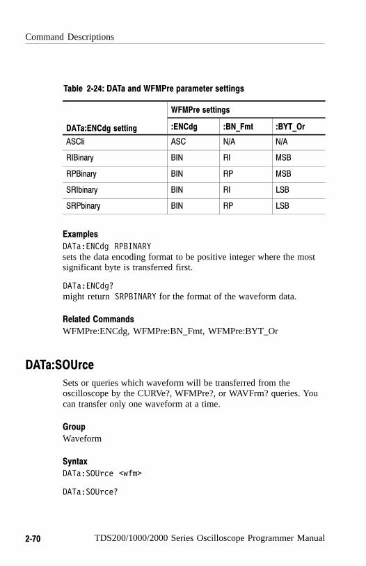
Command Descriptions
2−70 TDS200/1000/2000 Series Oscilloscope Programmer Manual
Table 2−24: DATa and WFMPre parameter settings
WFMPre settings
DATa:ENCdg setting :ENCdg :BN_Fmt :BYT_Or
ASCIi ASC N/A N/A
RIBinary BIN RI MSB
RPBinary BIN RP MSB
SRIbinary BIN RI LSB
SRPbinary BIN RP LSB
DATa:ENCdg RPBINARYsets the data encoding format to be positive integer where the mostsignificant byte is transferred first.
DATa:ENCdg?might return SRPBINARY for the format of the waveform data.
WFMPre:ENCdg, WFMPre:BN_Fmt, WFMPre:BYT_Or
DATa:SOUrce
Sets or queries which waveform will be transferred from theoscilloscope by the CURVe?, WFMPre?, or WAVFrm? queries. Youcan transfer only one waveform at a time.
Waveform
DATa:SOUrce <wfm>
DATa:SOUrce?
Examples
Related Commands
Group
Syntax

Command Descriptions
TDS200/1000/2000 Series Oscilloscope Programmer Manual 2−71
<wfm> is the location of the waveform data that will be transferredfrom the oscilloscope to the external device. Allowable values areCH<x>, MATH, and REF<x>.
DATa:SOUrce REFBspecifies that reference waveform REFB will be transferred in thenext CURVe? query.
DATa:SOUrce?might return REFA, indicating the source for the waveform data thatis transferred using CURVe?.
CURVe?, WFMPre?, WAVFrm?
DATa:STARt
Sets or queries the starting data point for waveform data transfers.This command lets you transfer partial waveforms to and from theoscilloscope.
Waveform
DATa:STARt <NR1>
DATa:STARt?
<NR1> is an integer value that ranges from 1 to 2500, and specifiesthe first data point that will be transferred. Data is transferred from<NR1> to DATa:STOP or 2500, whichever is less. WhenDATa:STOP is less than DATa:STARt, the values are swappedinternally for CURVe?.
Arguments
Examples
Related Commands
Group
Syntax
Arguments

Command Descriptions
2−72 TDS200/1000/2000 Series Oscilloscope Programmer Manual
DATa:STARt 10specifies that the waveform transfer will begin with data point 10.
DATa:STARt?might return 214 as the first waveform data point that will betransferred.
CURVe?
DATa:STOP
Sets or queries the last data point in the waveform that will betransferred when executing the CURVe? command. This lets youtransfer partial waveforms from the oscilloscope.
When using the CURVe command, the oscilloscope stops readingdata when there is no more data to read or when the 2500 data pointlimit is reached.
Waveform
DATa:STOP <NR1>
DATa:STOP?
<NR1> is an integer value that ranges from 1 to 2500, and specifiesthe last data point that will be transferred. When DATa:STOP is lessthan DATa:STARt, the values are swapped internally for CURVe?.
If you always want to transfer complete waveforms, set DATa:STARtto 1 and DATa:STOP to 2500.
Examples
Related Commands
Group
Syntax
Arguments
Command Descriptions
TDS200/1000/2000 Series Oscilloscope Programmer Manual 2−73
DATa:STOP 150specifies that the waveform transfer will stop at data point 150.
DATa:STOP?might return 285 as the last data point that will be transferred.
CURVe?
DATa:TARget
Sets or queries the location for storing waveform data transferredfrom an external device to the oscilloscope when executing theCURVe command. This command is equivalent to the DATa:DES-Tination command and is included here for compatibility with olderTektronix oscilloscopes.
DATa:WIDth
Sets the number of bytes per waveform data point to be transferredwhen executing the CURVe command. (Changing DATa:WIDth maychange the following WFMPre parameters: BIT_Nr, BYT_Nr,YMULt, YOFf, and YZEro.)
Waveform
DATa:WIDth <NR1>
DATa:WIDth?
<NR1> = 1 sets the number of bytes per waveform data point to 1byte (8 bits).
Examples
Related Commands
Group
Syntax
Arguments
Command Descriptions
2−74 TDS200/1000/2000 Series Oscilloscope Programmer Manual
<NR1> = 2 sets the number of bytes per waveform data point to2 bytes (16 bits). If DATa:WIDth is set to 2, the least significant byteis always zero.
DATa:WIDth 1sets the data width to 1 byte per data point for CURVe data.
CURVe, WFMPre:BIT_Nr, WFMPre:BYT_Nr
*DDT
Lets you specify a command or a list of commands to execute whenthe oscilloscope receives a *TRG command or the GET GPIBinterface message. This is a special alias that *TRG uses.
Miscellaneous
*DDT { <Block> | <QString> }
*DDT?
<Block> or <QString> is a complete sequence of program messages.The messages must contain only valid commands that must beseparated by semicolons and must follow all rules for concatenatingcommands (refer to page 2-6). The sequence must be ≤80 characters.<Block> format is always returned as a query response.
*DDT #217ACQuire:STATE RUN<EOI>specifies that the acquisition system will be started each time a*TRG command is sent.
Examples
Related Commands
Group
Syntax
Arguments
Examples

Command Descriptions
TDS200/1000/2000 Series Oscilloscope Programmer Manual 2−75
*TRG
DESE
Sets and queries the bits in the Device Event Status Enable Register(DESER). The DESER is the mask that determines whether or notevents are reported to the Standard Event Status Register (SESR),and entered into the Event Queue. Refer to the Status and Eventschapter on page 3-1 for more information.
Status and Error
DESE <NR1>
DESE?
<NR1> is an integer value in the range from 0 to 255. The binary bitsof DESER are set according to this value. For example, DESE 209sets the DESER to the binary value 11010001 (that is, the mostsignificant bit in the register is set to 1, the next most significant bitto 1, the next bit to 0, and so on).
The power-on default for DESER is all bits set to 1 if *PSC is 1. If*PSC is 0, the DESER maintains its value through a power cycle.
NOTE. Setting DESER and ESER to the same value allows only thosecodes to be entered into the Event Queue and summarized on theESB bit (bit 5) of the Status Byte Register. Use the *ESE command toset ESER. For more information on event handling, refer to theStatus and Events chapter.
Related Commands
Group
Syntax
Arguments
Command Descriptions
2−76 TDS200/1000/2000 Series Oscilloscope Programmer Manual
DESE 209sets the DESER to binary 11010001, which enables the PON, URQ,EXE, and OPC bits.
DESE?might return the string :DESE 186, showing that DESERcontains the binary value 10111010.
*CLS, *ESE, *ESR?, EVENT?, EVMsg?, *SRE, *STB?
DIAg:RESUlt:FLAg? (Query Only)
Returns the Pass/Fail status from the last diagnostic test sequenceexecution (those run automatically at power on, or those requestedthrough the Service Menu). Use the DIAg:RESUlt:LOG? query todetermine which test(s) has failed.
Calibration and Diagnostic
DIAg:RESUlt:FLAg?
PASS means that the oscilloscope passes all diagnostic tests.
FAIL means that the oscilloscope has failed at least one of thediagnostic tests.
DIAg:RESUlt:FLAG?returns either PASS or FAIL.
Examples
Related Commands
Group
Syntax
Returns
Examples

Command Descriptions
TDS200/1000/2000 Series Oscilloscope Programmer Manual 2−77
DIAg:RESUlt:LOG? (Query Only)
Returns the internal results log from the last diagnostic test sequenceexecution (those run automatically at power on, or those requestedthrough the Service Menu). The list contains all modules and moduleinterfaces that were tested along with the pass or fail status of each.
Calibration and Diagnostic
DIAg:RESUlt:LOG?
<QString> in the following format:
<Status>,<Module name>[,<Status>,<Module name>...]
DIAg:RESUlt:LOG?might return Npass−CPU, pass−ACQ1, pass−EXTENSION" forpower-up diagnostics.
DISplay? (Query Only)
Returns the current display settings.
Display
DISplay?
The current display settings
Group
Syntax
Returns
Examples
Group
Syntax
Returns

Command Descriptions
2−78 TDS200/1000/2000 Series Oscilloscope Programmer Manual
DISplay?might return :DISPLAY:FORMAT YT;STYLE VECTORS;PERSISTENCE OFF;CONTRAST 50; INVERT OFF
DISplay:CONTRast
Sets or queries the contrast of the LCD display. This command isequivalent to setting the Contrast option in the Display menu.
Display
DISplay:CONTRast <NR1>
DISplay:CONTRast?
<NR1> is an integer in the range from 1 through 100. The larger thevalue, the greater the screen contrast.
DISplay:CONTRast 63sets the display contrast to 63.
Related Commands, TDS1000 and TDS2000 Series Only
DISPLAY:INVert
DISplay:FORMat
Sets or queries the oscilloscope display format. This command isequivalent to setting the Format option in the Display menu.
Display
Examples
Group
Syntax
Arguments
Examples
Group
Command Descriptions
TDS200/1000/2000 Series Oscilloscope Programmer Manual 2−79
DISplay:FORMat { XY | YT }
DISplay:FORMat?
XY displays the voltage of channel 1 (horizontal axis) against thevoltage of channel 2 (vertical axis).
NOTE. Setting the display format to XY turns cursors off. Sending theCURSor:FUNCtion command when the display format is XY causesthe oscilloscope to generate event 221 (Settings conflict) and leavesthe display in XY format.
YT sets the display to vertical values versus time format and is thedefault mode.
DISplay:FORMat YTselects a voltage versus time format for the display.
DISplay:FORMat?might return XY for the display format.
DISplay:INVert
Sets or queries the TDS1000 display format. This command isequivalent to setting the Display Style option in the Utility Optionsmenu for the TDS1000 series.
The TDS2000-Series does not have a Display Style option, butaccepts the DISplay:INVert command and query for compatibility.The query always returns OFF.
The TDS200 series is not supported.
Display
Syntax
Arguments
Examples
Group
Command Descriptions
2−80 TDS200/1000/2000 Series Oscilloscope Programmer Manual
DISplay:INVert { ON | OFF}
DISplay:INVert?
OFF chooses a default black-on-white display.
ON chooses a white-on-black display.
DISplay:PERSistence
Sets the length of time that data points are displayed.
Display
DISplay:PERSistence { 1 | 2 | 5 | INF | OFF }
DISplay:PERSistence?
1 | 2 | 5 specifies the length, in seconds, that the waveform pointsare displayed on the screen.
INF specifies infinite persistence.
OFF specifies that persistence is turned off.
0 means that the persistence is turned off.
2 or 5 means that the persistence is set to two or five seconds.
99 means that the persistence is set to infinite.
DISplay:PERSistence 5specifies that the waveform points are displayed on the screen forfive seconds before they fade.
Syntax
Arguments
Group
Syntax
Arguments
Returns
Examples
Command Descriptions
TDS200/1000/2000 Series Oscilloscope Programmer Manual 2−81
DISplay:STYle
Selects how to display the waveform data. This command isequivalent to setting the Type option in the Display menu.
Display
DISplay:STYle { DOTs | VECtors }
DISplay:STYle?
DOTs displays individual data points.
VECtors connects adjacent data points.
DISplay:STYle VECsets the display to connect adjacent data points.
DISplay:STYle?might return DOTS indicating that the display shows individualwaveform data points.
ERRLOG:FIRST? (Query Only)
Returns the first entry in the error log, or an empty string if the errorlog is empty. Use this command along with ERRLOG:NEXT? toretrieve error log messages.
Calibration and Diagnostic
ERRLOG:FIRST?
Group
Syntax
Arguments
Examples
Group
Syntax

Command Descriptions
2−82 TDS200/1000/2000 Series Oscilloscope Programmer Manual
Refer to the service manual for your oscilloscope for informationabout error log message format.
ERRLOG:NEXT? (Query Only)
Returns the next entry in the error log, or an empty string if the errorlog is empty or you have reached the end of the log. To start at thetop of the error log, run the ERRLOG:FIRST? query to return thefirst error log message. Then use the ERRLOG:NEXT? query to stepthrough the error log.
Calibration and Diagnostic
ERRLOG:NEXT?
Refer to the service manual for your oscilloscope for informationabout error log message format.
*ESE
Sets and queries the bits in the Event Status Enable Register (ESER).The ESER prevents events from being reported to the Status ByteRegister (STB). Refer to the Status and Events chapter on page 3-1for more information.
Status and Error
*ESE <NR1>
*ESE?
Returns
Group
Syntax
Returns
Group
Syntax
Command Descriptions
TDS200/1000/2000 Series Oscilloscope Programmer Manual 2−83
<NR1> is a value in the range from 0 through 255. The binary bits ofthe ESER are set according to this value.
The power-on default for ESER is 0 if *PSC is 1. If *PSC is 0, theESER maintains its value through a power cycle.
NOTE. Setting the DESER and the ESER to the same value allowsonly those codes to be entered into the Event Queue and summarizedon the ESB bit (bit 5) of the Status Byte Register. Use the DESEcommand to set the DESER. Refer to Event Handling Sequence onpage 3-8 for more information.
*ESE 209sets the ESER to binary 11010001, which enables the PON, URQ,EXE, and OPC bits.
*ESE?might return the string *ESE 186, showing that the ESER containsthe binary value 10111010.
*CLS, DESE, *ESR?, EVENT?, EVMsg? *SRE, *STB?
Arguments
Examples
Related Commands

Command Descriptions
2−84 TDS200/1000/2000 Series Oscilloscope Programmer Manual
*ESR? (Query Only)
Returns the contents of the Standard Event Status Register (SESR).*ESR? also clears the SESR (since reading the SESR clears it).Refer to the Status and Events chapter on page 3-1 for moreinformation.
Status and Error
*ESR?
Contents of the Standard Event Status Register.
*ESR?might return the value 213, showing that the SESR contains binary11010101.
ALLEv?, *CLS, DESE, *ESE, EVENT?, EVMsg?, *OPC, *SRE,*STB?
EVENT? (Query Only)
Returns from the Event Queue an event code that providesinformation about the results of the last *ESR? read. EVENT? alsoremoves the returned value from the Event Queue. Refer to EventHandling Sequence on page 3-8 for for more information.
Status and Error
EVENT?
Group
Syntax
Returns
Examples
Related Commands
Group
Syntax
Command Descriptions
TDS200/1000/2000 Series Oscilloscope Programmer Manual 2−85
<NR1>
EVENT?might return the response :EVENT 110, showing that there was anerror in a command header.
ALLEv?, *CLS, DESE, *ESE, *ESR?, EVMsg?, *SRE, *STB?
EVMsg? (Query Only)
Removes from the Event Queue a single event code associated withthe results of the last *ESR? read, and returns the event code alongwith an explanatory message. Refer to Event Handling Sequence onpage 3-8 for for more information.
Status and Error
EVMsg?
The event code and message in the following format:
<Event Code><Comma><QString>[<Event Code><Comma><QString>...]
<QString>::= <Message>;[<Command>]
where <Command> is the command that caused the error and maybe returned when a command error is detected by the oscilloscope.As much of the command as possible is returned without exceedingthe 60 character limit of the <Message> and <Command> stringscombined. The command string is right-justified.
Returns
Examples
Related Commands
Group
Syntax
Returns

Command Descriptions
2−86 TDS200/1000/2000 Series Oscilloscope Programmer Manual
EVMsg?might return the message :EVMSG 110, NCommand header error"
ALLEv?, *CLS, DESE, *ESE, *ESR?, EVENT?, *SRE, *STB?
EVQty? (Query Only)
Returns the number of event codes that are in the Event Queue. Thisis useful when using ALLEv? since it lets you know exactly howmany events will be returned.
Status and Error
EVQty?
<NR1>
EVQty?might return 3 as the number of event codes in the Event Queue.
ALLEv?, EVENT?, EVMsg?
FACtory (No Query Form)
Resets the oscilloscope to its factory default settings. Refer toAppendix B for a list of the factory default settings.
Miscellaneous
Examples
Related Commands
Group
Syntax
Returns
Examples
Related Commands
Group

Command Descriptions
TDS200/1000/2000 Series Oscilloscope Programmer Manual 2−87
FACtory
Setting the oscilloscope to factory default has the following impacton the programming interface:
� Clears the Event Status Enable Register
� Clears the Service Request Enable Register
� Sets the Device Event Status Enable Register to 255
� Sets the Power On Status Clear Flag to TRUE
� Enables all Command Headers (HEADer ON)
� Sets the macro defined by *DDT to a “zero-length field”
� Clears the pending operation flag and associated operations
� Performs the equivalent of DATA INIT
The FACtory command does not alter the following items:
� State of the RS-232 or GPIB interface
� Selected GPIB address
� Front panel LOCK state
� Verbose state
� Display Contrast, TDS1000 and TDS2000 series only
� Calibration data that affects device specifications
� Stored settings
� Stored waveforms or data
� Hard copy parameters
� Display messages language selection
Refer to Appendix B: Factory Setup.
*PSC, *RCL, RECAll:SETUp, *RST, *SAV, SAVe:SETUp
Syntax
Examples
Related Commands

Command Descriptions
2−88 TDS200/1000/2000 Series Oscilloscope Programmer Manual
HARDCopy
Sends a copy of the screen display followed by an EOI to the portspecified by HARDCopy:PORT. The format and layout of the outputis specified with the HARDCopy:FORMat and HARDCopy:LAYoutcommands. This command is equivalent to pressing the PRINTbutton on the front panel of the TDS1000 and TDS2000 series or theHARDCOPY button on the front panel of the TDS200 series.
HARDCopy? returns format, layout, and port information.
NOTE. This command is not IEEE Std 488.2–1987 compatible.
Hard copy
HARDCopy { ABOrt | STARt }
HARDCopy?
ABOrt terminates the hard copy output in process.
NOTE. DCL does not clear the output queue once a hard copy is inprocess. The only way to abort the hard copy process is to send theHARDCopy ABOrt command. The output queue can then be clearedby sending a DCL message.
STARt initiates a screen copy that is sent to the port specified by theHARDCOPY:PORT command.
Group
Syntax
Arguments
Command Descriptions
TDS200/1000/2000 Series Oscilloscope Programmer Manual 2−89
NOTE. Use the *WAI command between HARDCopy STARtcommands to ensure that the first hard copy is complete beforestarting another.
HARDCopy ABOrtstops any hard copy output that is in process.
*WAI
HARDCopy:FORMat
Sets the hard copy output data format. This command is the same assetting the Format option in the UTILITY � Options � Hard CopySetup menu.
Hard copy
HARDCopy:FORMat { BMP | BUBBLEJet | DESKJet | DPU3445 |DPU411 | DPU412 | EPSIMAGE | EPSOn | INTERLEAF |LASERJet | PCX | RLE | THINKjet | TIFF}
HARDCopy:FORMat?
BMP sets the hard copy output format to Microsoft Windows Bitmapformat.
Examples
Related Commands
Group
Syntax
Arguments

Command Descriptions
2−90 TDS200/1000/2000 Series Oscilloscope Programmer Manual
BUBBLEJet (TDS1000 and TDS2000 series only) sets the hard copyoutput format to Canon Bubblejet format.
DESKjet sets the hard copy output format to HP DeskJet format.
DPU3445 (TDS1000 and TDS2000 series only), DPU411 andDPU412 set the hard copy ouput format to various Seiko formats.
EPSIMAGE sets the hard copy format data to Postscript format.
EPSOn sets the hard copy output format to 9-pin or 24-pin dot matrixprinter format.
INTERLEAF (TDS200 series only) sets the hard copy format data toInterleaf file format.
LASERJet sets the hard copy output format to HP LaserJet II printerformat.
PCX sets the hard copy output format to DOS Paintbrush format.
RLE (TDS1000 and TDS2000 series only) sets the hard copy outputformat to Run Length Encoded.
THINKjet sets the hard copy output format to HP Thinkjet printerformat.
TIFF (TDS1000 and TDS2000 series only) sets the hard copy outputformat to Tagged Image File Format.
HARDCopy:FORMat LASERJetsets the hard copy output format to LaserJetII.
HARDCopy:FORMat?might return EPSON as the hard copy output format.
Examples
Command Descriptions
TDS200/1000/2000 Series Oscilloscope Programmer Manual 2−91
HARDCopy:INKSaver
NOTE. This command ONLY affects the TDS2000 series.
Sets the TDS2000 Ink Saver feature to on or off. This command isequivalent to setting the Ink Saver option in the TDS2000 seriesUTILITY � Options � Printer Setup menu. This command has noeffect in TDS1000 oscilloscopes, but is accepted for compatibility.
Hard copy
HARDCopy:INKSaver { ON | OFF }
HARDCopy:INKSaver?
OFF prints “WYSIWYG” hardcopies, with color waveforms on ablack background.
ON (default) prints color waveforms on a white background.
HARDCopy:INKSaver?might return ON
HARDCopy:LAYout
Selects the printing orientation. This command is equivalent tosetting the Layout option in the UTILITY � Options � Hard CopySetup menu.
Hard copy
Group
Syntax
Arguments
Examples
Group

Command Descriptions
2−92 TDS200/1000/2000 Series Oscilloscope Programmer Manual
HARDCopy:LAYout { LANdscape | PORTRait }
HARDCopy:LAYout?
LANdscape specifies that the bottom of the hard copy is along thelong side of the piece of paper.
PORTRait specifies that the bottom of the hard copy is along theshort side of the piece of paper. This is the standard format.
HARDCopy:LAYout?might return PORTRAIT as the page layout format of the hard copyoutput.
HARDCopy:PORT
Selects where to send the hard copy data when the oscilloscopereceives the next HARDCOPY STARt command. This command isequivalent to setting the Port option in the UTILITY � Options �Hard Copy Setup menu.
Hard copy
HARDCopy:PORT { CENtronics | RS232 | GPIb }
HARDCopy:PORT?
CENtronics specifies that the hard copy data is sent out theCentronics port.
RS232 specifies that the hard copy data is sent out the RS232 port.
GPIb specifies that the hard copy data is sent out the GPIB port.
Syntax
Arguments
Examples
Group
Syntax
Arguments

Command Descriptions
TDS200/1000/2000 Series Oscilloscope Programmer Manual 2−93
HARDCopy:PORT?might return RS232 as the selected hard copy output port.
HDR
This command is identical to the HEADer query and is included forcompatibility with other Tektronix oscilloscopes.
HEADer
Sets and queries the Response Header Enable State that causes theoscilloscope to either include or omit headers on query responses.This command does not affect IEEE Std 488.2–1987 CommonCommands (those starting with an asterisk); they never returnheaders.
Miscellaneous
HEADer { <NR1> | OFF | ON }
HEADer?
ON or <NR1> ≠ 0 sets the Response Header Enable State to true. Thiscauses the oscilloscope to include headers on applicable queryresponses. You can then use the query response as a command.
OFF or <NR1> = 0 sets the Response Header Enable State to false.This causes the oscilloscope to omit headers on query responses sothat only the argument is returned.
HEADer OFFcauses the oscilloscope to omit headers from query responses.
Examples
Group
Syntax
Arguments
Examples
Command Descriptions
2−94 TDS200/1000/2000 Series Oscilloscope Programmer Manual
HEADer?might return the value 1, showing that the Response Header EnableState is true.
VERBose
HORizontal? (Query Only)
Returns all settings for the horizontal commands. The commandsHORizontal:MAIn:SCAle, HORizontal:MAIn:SECdiv, HORizon-tal:SCAle, and HORizontal:SECdiv are equivalent, so HORizon-tal:MAIn:SCAle is the value that is returned.
The commands HORizontal:MAIn:POSition and HORizontal:POSi-tion are equivalent, so HORizontal:MAIn:POSition is the value thatis returned.
Horizontal
HORizontal?
Returns all horizontal settings
HORizontal?might return the string :HORIZONTAL:VIEW MAIN;RECORDLENGTH 2500;MAIN:POSITION0.0E0;SCALE 5.0E–4;HORIZONTAL:DELAY:POSITION 0.0E0;SCALE 2.5E–4
Related Commands
Group
Syntax
Returns
Examples
Command Descriptions
TDS200/1000/2000 Series Oscilloscope Programmer Manual 2−95
HORizontal:DELay? (Query Only)
Returns all settings for the window time base. The commandsHORizontal:DELay:SECdiv and HORizontal:DELay:SCAle areequivalent, so only the values for HORizontal:DELay:SCAle arereturned.
Horizontal
HORizontal:DELay?
All settings for the window time base
HORizontal:DELay?might return :HORIZONTAL:DELAY:POSITION 0.0E0;SCALE 5.0E–4
HORizontal:DELay:POSition
Sets or queries the window time base horizontal position. Thiscommand is equivalent to adjusting the Horizontal Position whenWindow Zone or Window is selected from the Horizontal menu.
Horizontal
HORizontal:DELay:POSition <NR3>
HORizontal:DELay:POSition?
Group
Syntax
Returns
Examples
Group
Syntax

Command Descriptions
2−96 TDS200/1000/2000 Series Oscilloscope Programmer Manual
<NR3> is the position in seconds. This value is the difference betweenthe trigger point and the center graticule. Positive values place thetrigger before the center graticule.
HORizontal:DELay:POSition 2.0E–6sets the window position to 2 �s before the center graticule.
HORizontal:DELay:POSition?might return –1.0E–3, indicating that the window position is 1�msafter the center graticule.
HORizontal:DELay:SCAle
Sets the time per division for the oscilloscope window time base.This command is equivalent to setting SEC/DIV when Window Zoneor Window is selected from the Horizontal menu.
Horizontal
HORizontal:DELay:SCAle <NR3>
HORizontal:DELay:SCAle?
<NR3> is the time per division. The range depends on the oscillo-scope model. The acceptable values are in a 1–2.5–5 sequence. If thewindow time base scale is set slower than the main time base scale,both the main and window time base scales are set to the windowscale value.
HORizontal:DELay:SCAle 2.0E–6sets the window scale to 2 �s per division.
Arguments
Examples
Group
Syntax
Arguments
Examples

Command Descriptions
TDS200/1000/2000 Series Oscilloscope Programmer Manual 2−97
HORizontal:DELay:SCAle 9.0E–6sets the window scale to 10 �s per division. Since 9 �s is not acorrect value within the 1–2.5–5 sequence, it is automatically set tothe closest correct value.
HORizontal:DELay:SCAle?might return 1.0E–3, indicating that the window scale is 1 ms perdivision.
HORizontal:DELay:SECdiv
This command is identical to the HORizontal:DELay:SCAle. It isprovided to maintain program compatibility with some older modelsof Tektronix oscilloscopes.
HORizontal:MAIn? (Query Only)
Returns all settings for the oscilloscope main time base. TheHORizontal:MAIn:SECdiv and HORizontal:MAIn:SCAle com-mands are identical so only HORizontal:MAIn:SCAle is returned.
Horizontal
HORizontal:MAIn?
All settings for the main time base.
HORizontal:MAIn?might return :HORIZONTAL:MAIN:POSITION 0.0E0;SCALE 5.0E–4
Group
Syntax
Returns
Examples

Command Descriptions
2−98 TDS200/1000/2000 Series Oscilloscope Programmer Manual
HORizontal:MAIn:POSition
Sets or queries the main time base horizontal position. Thiscommand is equivalent to adjusting the Horizontal Position whenMain is selected from the Horizontal menu.
Horizontal
HORizontal:MAIn:POSition <NR3>
HORizontal:MAIn:POSition?
<NR3> is the position in seconds. This value is the difference betweenthe trigger point and the center graticule. Positive values place thetrigger before the center graticule.
HORizontal:MAIn:POSition 2.0E–6sets the main trigger position to 2 �s before the center graticule.
HORizontal:MAIn:POSition?might return –1.0E–3, indicating that the main trigger position is 1ms after the center graticule.
HORizontal:MAIn:SCAle
Sets the time per division for the main time base. This command isequivalent to setting SEC/DIV when Main is selected from theHorizontal menu.
Horizontal
Group
Syntax
Arguments
Examples
Group

Command Descriptions
TDS200/1000/2000 Series Oscilloscope Programmer Manual 2−99
HORizontal:MAIn:SCAle <NR3>
HORizontal:MAIn:SCAle?
<NR3> is the time per division. The range depends on the oscillo-scope model. The acceptable values are in a 1–2.5–5 sequence.Other values are forced to the closest acceptable value.
HORizontal:MAIn:SCAle 2.5E–6sets the main scale to 2.5 �s per division.
HORizontal:MAIn:SECdiv
Sets the time per division for the oscilloscope main time base. Thiscommand is identical to the HORizontal:MAIn:SCAle command. Itis provided to maintain program compatibility with some oldermodels of Tektronix oscilloscopes.
HORizontal:POSition
Sets or queries the main time base horizontal position. Thiscommand is identical to the HORizontal:MAIn:POSition command.This command is included for compatibility.
Horizontal
HORizontal:POSition <NR3>
HORizontal:POSition?
<NR3> is the position in seconds. This value is the difference betweenthe trigger point and the center graticule. Positive values place thetrigger before the center graticule.
Syntax
Arguments
Examples
Group
Syntax
Arguments
Command Descriptions
2−100 TDS200/1000/2000 Series Oscilloscope Programmer Manual
HORizontal:POSition 2.0E–6sets the main trigger position to 2 �s before the center graticule.
HORizontal:POSition?might return –1.0E–3, indicating that the main trigger position is 1ms after the center graticule.
HORizontal:RECOrdlength? (Query Only)
Returns the number of acquisition data points. For TDS200,TDS1000 and TDS2000 series oscilloscopes, this value is always2500, even in FFT mode. This command is provided to maintainprogram compatibility with other Tektronix digital oscilloscopes.
Horizontal
HORizontal:RECOrdlength?
2500
HORizontal:RECOrdlength?returns 2500 as the number of data points in each record.
WFMPre:NR_Pt?, WFMPre:<wfm>:NR_Pt?
HORizontal:SCAle
Sets the time per division for the main time base and is identical tothe HORizontal:MAIn:SCAle command. It is included for compati-bility purposes.
Examples
Group
Syntax
Returns
Examples
Related Commands

Command Descriptions
TDS200/1000/2000 Series Oscilloscope Programmer Manual 2−101
HORizontal:SECdiv
Sets the time per division for the main time base and is identical tothe HORizontal:MAIn:SCAle command. It is included for compati-bility purposes.
HORizontal:VIEW
Specifies whether the horizontal display uses the Main, WindowZone, or Window view. This is equivalent to setting the View in theHorizontal menu.
Horizontal
HORizontal:VIEW { MAIn | WINDOW | ZONE }
HORizontal:VIEW?
MAIn specifies that the waveform is acquired and displayed using theMain time base.
WINDOW specifies that the waveform is acquired and displayed usingthe Window (delay) time base.
ZONE is the same as MAIn, but adds display of vertical cursor bars toshow the portion of the waveform that would be acquired anddisplayed using the window (delay) time base.
HORizontal:VIEW MAInis the default view.
Group
Syntax
Arguments
Examples

Command Descriptions
2−102 TDS200/1000/2000 Series Oscilloscope Programmer Manual
ID? (Query Only)
Returns identifying information about the oscilloscope and itsfirmware in Tektronix Codes and Formats notation.
NOTE. ID? must be the last command when it is part of a concate-nated statement. Otherwise the oscilloscope generates event message440.
Status and Events
ID?
The oscilloscope identification in the following format:
TEK/<model number>,CF:91.1CT,FV:v<oscilloscope firmwareversion number>,TDS2XX:XXV:v<module firmware versionnumber>
Where XX is the module type, CM (communications module) orMM (measurement module).
The *IDN? and ID? responses are slightly different.
ID?might return the responseID TEK/TDS 220,CF:91.1CT,FV:v1.00 TDS2CM:CMV:v1.00
*IDN?
Group
Syntax
Returns
Examples
Related Commands

Command Descriptions
TDS200/1000/2000 Series Oscilloscope Programmer Manual 2−103
*IDN? (Query Only)
Returns the oscilloscope identification code in IEEE 488.2 notation.
NOTE. IDN? must be the last command when it is part of aconcatenated statement. Otherwise the oscilloscope generates eventmessage 440.
Status and Events
*IDN?
The oscilloscope identification in the following format:
TEKTRONIX,<model number>,0,CF:91.1CT FV:v<oscilloscopefirmware version number> TDS2XX:XXV:v<module firmwareversion number>
Where XX is the module type, CM (communications module) orMM (measurement module).
The *IDN? and ID? responses are slightly different.
*IDN?might return the responseTEKTRONIX,TDS 220,0,CF:91.1CT FV:v1.00 TDS2CM:CMV:v1.00
ID?
Group
Syntax
Returns
Examples
Related Commands

Command Descriptions
2−104 TDS200/1000/2000 Series Oscilloscope Programmer Manual
LANGuage
Sets or queries the languages that the oscilloscope uses to displayinformation on the screen. This is equivalent to the Language optionin the Utility menu.
Miscellaneous
LANGuage { ENGLish | FRENch | GERMan | ITALian |PORTUguese | SPANish | JAPAnese | KOREan | TRADitionalchinese | SIMPlifiedchinese }
LANGuage?
The argument specifies which language will be used to displayoscilloscope information on the screen.
LANGuage FRENchspecifies that the oscilloscope display information in French.
LANGuage?might return SPANISH
LOCk
Enables and disables all front-panel buttons and knobs. There is nofront-panel equivalent.
Miscellaneous
LOCk { ALL | NONe }
LOCk?
Group
Syntax
Arguments
Examples
Group
Syntax

Command Descriptions
TDS200/1000/2000 Series Oscilloscope Programmer Manual 2−105
ALL disables all front-panel controls.
NONe enables all front-panel controls. This is equivalent to theUNLock ALL command.
LOCk ALLlocks the front-panel controls.
LOCk?returns NONE when the front-panel controls are enabled by thiscommand.
UNLock
*LRN? (Query Only)
This is identical to the SET? query described on page 2-134.
Miscellaneous
*LRN?
MATH? (Query Only)
Returns the definition for the math waveform.
Vertical
MATH?
Arguments
Examples
Related Commands
Group
Syntax
Group
Syntax
Command Descriptions
2−106 TDS200/1000/2000 Series Oscilloscope Programmer Manual
Definition for the math waveform.
MATH?returns :MATH:DEFINE NCH1 + CH2" if the math waveform isdefined as channel 1 plus channel 2.
MATH:DEFINE
Performs the specified mathematical operation on the input signal orsignals. To activate or deactivate the math waveform, use theSELect:<wfm> command (refer to page 2-134).
Vertical
MATH:DEFINE <QString>
MATH:DEFINE?
NOTE. Remember that <QString> must be enclosed in quotes. Youcan use white space characters between words.
<QString> specifies a math waveform, and can be one of thefollowing:
TDS1002, TDS1012, TDS2002, TDS2012 and TDS2022 models; TDS210 andTDS220 models (firmware V2.00 and above) with a TDS2MM measurementmodule.
CH1+CH2CH1–CH2CH2–CH1FFT (CH<x> [, <window>])
Returns
Examples
Group
Syntax
Arguments

Command Descriptions
TDS200/1000/2000 Series Oscilloscope Programmer Manual 2−107
TDS2014 and TDS2024 models; TDS224 model with a TDS2MM measure−ment module.
CH1+CH2CH3+CH4CH1–CH2CH2–CH1CH3–CH4CH4–CH3FFT (CH<x> [, <window>])
TDS210 and TDS220 models, firmware below V2.00 with a TDS2CMAcommunications module.
CH1–CH2 CH2–CH1 CH1+CH2–CH1 –CH2
TDS210 and TDS220 models (firmware below V2.00) with a TDS2MMmeasurement module.
CH1+CH2(to subtract, invert one of the waveforms through CH<x>:INVert,and then add)FFT (CH<x> [, <window>])
TDS210 and TDS220 models (firmware V2.00) and above with a TDS2CMAcommunications module.
CH1+CH2CH1–CH2CH2–CH1
TDS224 model with a TDS2CMA communications module.
CH1+CH2CH3+CH4CH1–CH2CH2–CH1CH3–CH4CH4–CH3

Command Descriptions
2−108 TDS200/1000/2000 Series Oscilloscope Programmer Manual
For FFT, the optional <window> argument is HANning, FLATtop, orRECTangular.
MATH:DEFINE NCH1+CH2"sets the math waveform so that it displays the sum of channel 1 andchannel 2.
MATH:DEFINE NFFT (CH1, HANNING)"sets the math waveform to display an FFT of channel 1 using aHanning window.
NOTE. You can use this example with a TDS1000 or TDS2000 series,as well as a TDS200 series with a TDS2MM measurement module.
MATH:FFT:HORizontal:POSition
NOTE. You can use this command with a TDS1000 or TDS2000series, as well as a TDS200 series with a TDS2MM measurementmodule.
Sets or queries the FFT math waveform horizontal position.
Horizontal
MATH:FFT:HORizontal:POSition <NR3>
MATH:FFT:HORizontal:POSition?
Examples
Group
Syntax

Command Descriptions
TDS200/1000/2000 Series Oscilloscope Programmer Manual 2−109
<NR3> specifies the point in the FFT waveform data record to displayat the center vertical graticule line. The data record point is apercentage of the total record length, in the range of 0 to 100. Thedefault value is 50. How much data is displayed depends on the FFTZoom factor setting. The oscilloscope rounds <NR3> to the nearestworkable value.
MATH:FFT:HORizontal:POSition 25sets the FFT waveform horizontal position such that the data at the25% point of the record is centered on the display.
MATH:FFT:HORizontal:POSition?might return 5.0E1, indicating that the 50% point in the data recordis horizontally centered on the display.
MATH:FFT:HORizontal:SCAle
NOTE. You can use this command with a TDS1000 or TDS2000series, as well as a TDS200 series with a TDS2MM measurementmodule.
Sets or queries the FFT math waveform horizontal zoom factor.
Horizontal
MATH:FFT:HORizontal:SCAle <NR3>
MATH:FFT:HORizontal:SCAle?
<NR3> specifies the horizontal magnification factor, where the axis ofmagnification is the center vertical graticule line. Valid zoom factorsare 1, 2, 5, and 10. If other values are entered the oscilloscoperounds the value of <NR3> to the nearest valid zoom factor.
Arguments
Examples
Group
Syntax
Arguments
Command Descriptions
2−1 10 TDS200/1000/2000 Series Oscilloscope Programmer Manual
MATH:FFT:HORizontal:SCAle 5sets the FFT waveform horizontal zoom factor to X5.
MATH:FFT:HORizontal:SCAle?might return 2.0E0, indicating that the zoom factor setting is X2.
MATH:FFT:VERtical:POSition
NOTE. You can use this command with a TDS1000 or TDS2000series, as well as a TDS200 series with a TDS2MM measurementmodule.
Sets or queries the FFT math waveform vertical position.
Vertical
MATH:FFT:VERtical:POSition <NR3>
MATH:FFT:VERtical:POSition?
<NR3> specifies the FFT waveform vertical position in divisions.
MATH:FFT:VERtical:POSition 2sets the FFT waveform vertical position to 2 major divisions abovethe center horizontal graticule line.
MATH:FFT:VERtical:POSition?might return 5, indicating that the FFT waveform 0 reference pointis 5 major divisions from the center horizontal graticule line.
Examples
Group
Syntax
Arguments
Examples

Command Descriptions
TDS200/1000/2000 Series Oscilloscope Programmer Manual 2−1 11
MATH:FFT:VERtical:SCAle
NOTE. You can use this command with a TDS1000 or TDS2000series, as well as a TDS200 series with a TDS2MM measurementmodule.
Sets or queries the FFT math waveform vertical zoom factor.
Vertical
MATH:FFT:VERtical:SCAle <NR3>
MATH:FFT:VERtical:SCAle?
<NR3> specifies the vertical zoom factor, where the axis ofmagnification is the center horizontal graticule line. Valid zoomfactors are 0.5, 1, 2, 5, and 10. If other values are entered theoscilloscope rounds the value of <NR3> to the nearest valid zoomfactor.
MATH:FFT:VERtical:SCAle 5sets the FFT waveform vertical zoom factor to X5.
MATH:FFT:VERtical:SCAle?might return 2.0E0, indicating that the zoom factor setting is X2.
MEASUrement? (Query Only)
Returns all oscilloscope measurement parameters.
Measurement
Group
Syntax
Arguments
Examples
Group

Command Descriptions
2−1 12 TDS200/1000/2000 Series Oscilloscope Programmer Manual
MEASUrement?
Oscilloscope measurement parameters
MEASUrement?might return the following:
:MEASUREMENT:MEAS1:TYPE PERIOD;UNITS Ns";SOURCE CH1;:MEASUREMENT:MEAS2:TYPE FREQUENCY;UNITS NHz";SOURCE CH1;:MEASUREMENT:MEAS3:TYPE PK2PK;UNITS NV";SOURCE CH2;:MEASUREMENT:MEAS4:TYPE MEAN;UNITS NV";SOURCE CH2;:MEASUREMENT:IMMED:TYPE CRMS;UNITS NV";SOURCE CH1
MEASUrement:IMMed? (Query Only)
Returns all immediate measurement setup parameters. Immediatequeries and commands are the preferred methods for programming.An immediate measurement selection is not visible or accessiblethrough the display screen or front panel.
Measurement
MEASUrement:IMMed?
Immediate measurement setup parameters
MEASUrement:IMMed?might return PERIOD;Ns";CH1
Syntax
Returns
Examples
Group
Syntax
Returns
Examples
Command Descriptions
TDS200/1000/2000 Series Oscilloscope Programmer Manual 2−1 13
MEASUrement:IMMed:SOUrce
Sets or queries the source for all immediate measurements.
Measurement
MEASUrement:IMMed:SOUrce CH<x>
MEASUrement:IMMed:SOUrce?
CH<x> is an input channel.
MEASUrement:IMMed:SOUrce CH1specifies channel 1 as the immediate measurement source.
MEASUrement:IMMed:TYPe
Sets or queries the immediate measurement type.
Measurement
MEASUrement:IMMed:TYPe { FREQuency | MEAN | PERIod |PK2pk | CRMs | MINImum | MAXImum | RISe | FALL | PWIdth| NWIdth }
MEASUrement:IMMed:TYPe?
FREQuency is the reciprocal of the period measured in Hertz.
MEAN is the arithmetic mean over the entire waveform.
Group
Syntax
Arguments
Examples
Group
Syntax
Arguments

Command Descriptions
2−1 14 TDS200/1000/2000 Series Oscilloscope Programmer Manual
PERIod is the duration, in seconds, of the first complete cycle in thewaveform.
PK2pk is the absolute difference between the maximum andminimum amplitude.
CRMs is the true Root Mean Square voltage of the first completecycle in the waveform.
MINImum (TDS1000 and TDS2000 series only) is the value of thesmallest point in the waveform.
MAXImum (TDS1000 and TDS2000 series only) is the value of thelargest point in the waveform.
RISe (TDS1000 and TDS2000 series, or TDS200 series with aTDS2MM measurement module only) is the rise time between 10%and 90% of the first rising edge of the waveform. Rising edge mustbe displayed to measure. The oscilloscope automatically calculatesthe 10% and 90% measurement points.
FALL (TDS1000 and TDS2000 series, or TDS200 series with aTDS2MM measurement module only) is the fall time between 90%and 10% of the first falling edge of the waveform. Falling edge mustbe displayed to measure. The oscilloscope automatically calculatesthe 10% and 90% measurement points.
PWIdth (TDS1000 and TDS2000 series, or TDS200 series with aTDS2MM measurement module only) is the positive pulse widthbetween the first rising edge and the next falling edge at thewaveform 50% level. Rising and falling edges must be displayed tomeasure. The oscilloscope automatically calculates the 50%measurement point.
NWIdth (TDS1000 and TDS2000 series, or TDS200 series with aTDS2MM measurement module only) is the negative pulse widthbetween the first falling edge and the next rising edge at thewaveform 50% level. Falling and rising edges must be displayed tomeasure. The oscilloscope automatically calculates the 50%measurement point.
MEASUrement:IMMed:TYPe FREQuencydefines the immediate measurement to be a frequency measurement.
Examples

Command Descriptions
TDS200/1000/2000 Series Oscilloscope Programmer Manual 2−1 15
MEASUrement:IMMed:UNIts? (Query Only)
Returns the units for the immediate oscilloscope measurement.
Measurement
MEASUrement:IMMed:UNIts?
<QString> returns NV" for volts, Ns" for seconds, or NHz" for Hertz.
MEASUrement:IMMed:UNIts?might return Ns", indicating that the unit for the immediatemeasurement is seconds.
MEASUrement:IMMed:VALue? (Query Only)
Executes the immediate oscilloscope measurement specified by theMEASUrement:IMMed:TYPe command. The measurement is takenon the source specified by the MEASUrement:IMMed:SOUrcecommand. Immediate queries and commands are the preferredmeasurement method for programming.
To check whether the measurement was successful, use the *ESR?query followed by the EVENT? or ALLEv? queries to read theStandard Event Status Register (SESR).
NOTE. If the channel specified by MEASUrement:IMMed:SOUrce isnot currently displayed, the oscilloscope generates event 2225 andreturns 9.9E37.
If Trigger View is active, Scan mode is in effect, or the display formatis set to XY, this query returns 9.9E37 and generates event 221(Settings conflict).
Group
Syntax
Returns
Examples

Command Descriptions
2−1 16 TDS200/1000/2000 Series Oscilloscope Programmer Manual
Measurement
MEASUrement:IMMed:VALue?
<NR3>
MEASUrement:IMMed:VALue?might return 28.75E6 if you are measuring the frequency of a28.75 MHz signal.
MEASUrement:IMMed:VALue?might return 9.9E37, which means that the channel specified byMEASUrement:IMMed:SOUrce is not currently displayed.
*ESR? after a measurement query might return 16, indicating that there areerror messages in the queue.
ALLEv?might return :ALLEV 541,NMeasurement warning, Low signalamplitude: "
*ESR?, EVENT?, ALLEv?
MEASUrement:MEAS<x>? (Query Only)
Returns all measurement parameters for the displayed oscilloscopeperiodic measurement specified by <x>, where <x> is 1 through 4for the TDS200 series, and 1 through 5 for the TDS1000 andTDS2000 series.
Measurement
Group
Syntax
Returns
Examples
Related Commands
Group

Command Descriptions
TDS200/1000/2000 Series Oscilloscope Programmer Manual 2−1 17
MEASUrement:MEAS<x>?
Settings for the specified measurement source.
MEASUrement:MEAS3?might return PERIOD;Ns";CH1
MEASUrement:MEAS<x>:SOUrce
Sets or queries the source for the measurement. This is equivalent toselecting the measurement source in the MEASURE menu.
Measurement
MEASUrement:MEAS<x>:SOUrce CH<y>
MEASUrement:MEAS<x>:SOUrce?
CH<y> specifies the measurement source channel.
MEASUrement:MEAS2:SOUrce CH1Sets the source of MEAS2 to channel 1.
MEASUrement:MEAS<x>:TYPe
Sets or queries the on-screen periodic oscilloscope measurement typefor the measurement specified by <x>. This is equivalent to selectingthe measurement type in the MEASURE menu. Setting the type toanything other than NONE displays the MEASURE menu on thescreen.
Syntax
Returns
Examples
Group
Syntax
Arguments
Examples

Command Descriptions
2−1 18 TDS200/1000/2000 Series Oscilloscope Programmer Manual
NOTE. You should use the MEASUrement:IMMed command withprogramming to take measurements, as this is preferred to theMEASUrement:MEAS<x>command.
Measurement
MEASUrement:MEAS<x>:TYPe { FREQuency | MEAN | PERIod |PK2pk | CRMs | MINImum | MAXImum | RISe | FALL | PWIdth| NWIdth | NONE }
MEASUrement:MEAS<x>:TYPe?
FREQuency is the reciprocal of the period measured in Hertz.
MEAN is the arithmetic mean over the entire waveform.
PERIod is the duration, in seconds, of the first complete cycle in thewaveform.
PK2pk is the absolute difference between the maximum andminimum amplitude.
CRMs is the true Root Mean Square voltage of the first completecycle in the waveform.
MINImum (TDS1000 and TDS2000 only) is the value of the smallestpoint in the waveform.
MAXImum (TDS1000 and TDS2000 only) is the value of the largestpoint in the waveform.
RISe (TDS1000 and TDS2000 series, or TDS200 series with aTDS2MM measurementmodule only) is the rise time between 10%and 90% of the first rising edge of the waveform. Rising edge mustbe displayed to measure. The oscilloscope automatically calculatesthe 10% and 90% measurement points.
Group
Syntax
Arguments
Command Descriptions
TDS200/1000/2000 Series Oscilloscope Programmer Manual 2−1 19
FALL (TDS1000 and TDS2000 series, or TDS200 series with aTDS2MM measurementmodule only) is the fall time between 90%and 10% of the first falling edge of the waveform. Falling edge mustbe displayed to measure. The oscilloscope automatically calculatesthe 10% and 90% measurement points.
PWIdth (TDS1000 and TDS2000 series, or TDS200 series with aTDS2MM measurementmodule only) is the positive pulse widthbetween the first rising edge and the next falling edge at thewaveform 50% level. Rising and falling edges must be displayed tomeasure. The oscilloscope automatically calculates the 50%measurement point.
NWIdth (TDS1000 and TDS2000 series, or TDS200 series with aTDS2MM measurementmodule only) is the negative pulse widthbetween the first falling edge and the next rising edge at thewaveform 50% level. Falling and rising edges must be displayed tomeasure. The oscilloscope automatically calculates the 50%measurement point.
NONE disables the measurement specified by <x>.
MEASUrement:MEAS3:TYPe CRMSspecifies MEAS3 to calculate the true Root Mean Square value.
MEASUrement:MEAS<x>:UNIts? (Query Only)
Returns the units for the oscilloscope measurement specified byMEASUrement:MEAS<x>:TYPe.
Measurement
MEASUrement:MEAS<x>:UNIts?
<QString> returns NV" for volts, Ns" for seconds, NHz" for Hertz, ora null string if MEASUrement:MEAS<x>:TYPe is set to NONE.
Examples
Group
Syntax
Returns

Command Descriptions
2−120 TDS200/1000/2000 Series Oscilloscope Programmer Manual
MEASUrement:MEAS3:UNIts?might return NV", indicating the units for measurement 3 are volts.
MEASUrement:MEAS<x>:VALue? (Query Only)
Returns the value that has been calculated for the oscilloscopeon-screen periodic measurement specified by <x>.
This value is a display value and will be updated about every 1/2second if both the MEASURE menu and the MEAS<x> sourcechannel are displayed. If you are acquiring at a slow sweep rate, theoscilloscope may take longer than 1/2 second to update. MEASure-ment:IMMed is usually more useful than MEASUrement:MEAS<x>when using the oscilloscope with external devices.
If MEASUrement:MEAS<x>:TYPe is set to NONE, MEASUre-ment:MEAS<x>:VALue? generates event message 2231 (Measure-ment error, measurement is not activated) and returns 9.9E37.
If the channel specified by MEASUrement:MEAS<x>:SOUrce is notdisplayed on the oscilloscope, the oscilloscope generates eventmessage 2225 (Measurement error, no waveform to measure) andreturns 9.9E37.
NOTE. If Trigger View is active, scan mode is in effect, or the displayformat set to XY, this query generates event 221 (Settings conflict)and returns 9.9E37.
Measurement
MEASUrement:MEAS<x>:VALue?
<NR3>
Examples
Group
Syntax
Returns

Command Descriptions
TDS200/1000/2000 Series Oscilloscope Programmer Manual 2−121
MEASUrement:MEAS3:VALue?might return 28.75E6 if measurement number three is frequency.
*OPC
The *OPC? query and the *OPC set command provide two differentmethods for checking for the completion of the commands listed inTable 2-21 on page 2-121, such as single sequence acquisitions.
The *OPC? query uses a more simple method than the *OPC setcommand. The *OPC? query places the ASCII character “1” into theoutput queue when all pending operations listed in Table 2-21 arecomplete. If none of the operations are pending, the *OPC? queryimmediately places a “1” in the output queue.
NOTE. When using the *OPC? query method, the time-out on yourcontroller must be set for longer than the operation for which thecontroller is waiting, such as a single sequence acquisition.
Unlike the *OPC command, the *OPC? query does not affect theOPC Event bit in the Standard Event Status Register (ESR).
The *OPC set command uses a more complex method than the*OPC? query. However, there are advantages to using this method insome situations. For more information, refer to Using the *OPC SetCommand on page 3-14. Table 2-25 lists commands that generate anOperation Complete message.
Table 2−25: Commands that generate an Operation Complete message
Command Operation
*CAL?, CALibrate:CONTINUE, CALIbrate:FACtory, CALIbrate:INTERNAL
Internal self−calibration
ACQuire:STATE ON orACQuire:STATE RUN (when ACQuire:STOPAfter is set to SEQuence)
Busy single sequence acquisition
HARDCopy STARt Busy hardcopy output
Examples

Command Descriptions
2−122 TDS200/1000/2000 Series Oscilloscope Programmer Manual
Status and Error
*OPC
*OPC?
Using the *OPC? query to check for completion of a single sequenceacquisition:
ACQuire:STOPAfter SEQUENCEACQuire:STATE ON *OPC? will return a 1 after the acquisition is complete.
Refer to page 3-14 for examples of how to use the *OPC setcommand.
ALLEv, BUSY?, DESE, *ESR?, *WAI
*PSC
Sets and queries the power-on status flag that controls the automaticpower-on handling of the DESER, SRER, and ESER registers. When*PSC is true, the DESER register is set to 255 and the SRER andESER registers are set to 0 at power on. When *PSC is false, thecurrent values in the DESER, SRER, and ESER registers arepreserved in nonvolatile memory when power is shut off and arerestored at power on. Refer to the Status and Events chapter on page 3-1 for more information.
Status and Error
*PSC <NR1>
*PSC?
Group
Syntax
Examples
Related Commands
Group
Syntax
Command Descriptions
TDS200/1000/2000 Series Oscilloscope Programmer Manual 2−123
<NR1> = 0 sets the power-on status clear flag to false, disables thepower on clear, and allows the oscilloscope to possibly assert SRQafter power on.
<NR1> ≠ 0 sets the power-on status clear flag true. Sending *PSC 1,therefore, enables the power-on status clear and prevents any SRQassertion after power on.
*PSC 0sets the power-on status clear flag to false.
*PSC?might return the value 1, showing that the power-on status clear flagis set to true.
DESE, *ESE, FACtory, *RST, *SRE
*RCL (No Query Form)
Restores the state of the oscilloscope from a copy of its settingsstored in memory. (The settings are stored using the *SAVcommand.) This command is equivalent to RECAll:SETUp, andperforms the same function as the Recall Saved Setup item in thefront-panel Save/Recall Setup menu.
Save and Recall
*RCL <NR1>
<NR1> is an integer value in the range from 1 to 5 (TDS200 series) or1 to 10 (TDS1000 and TDS2000 series), and specifies a setup storagelocation.
Arguments
Examples
Related Commands
Group
Syntax
Arguments
Command Descriptions
2−124 TDS200/1000/2000 Series Oscilloscope Programmer Manual
*RCL 3restores the oscilloscope from a copy of the settings stored inmemory location 3.
FACtory, *LRN?, RECAll:SETUp, *RST, *SAV, SAVe:SETUp
RECAll:SETUp (No Query Form)
Restores a stored or factory front-panel setup of the oscilloscope.This command is equivalent to selecting Recall Setup or RecallFactory in the Save/Recall Setup menu.
Save and Recall
RECAll:SETUp { FACtory | <NR1> }
FACtory selects the factory setup.
<NR1> is a value in the range from 1 to 5 (TDS200 series) or 10(TDS1000 and TDS2000 series) and specifies a setup storagelocation.
RECALL:SETUp FACtoryrecalls the front-panel setup to its factory defaults.
FACtory, *RCL, *RST, *SAV, SAVe:SETUp
Examples
Related Commands
Group
Syntax
Arguments
Examples
Related Commands

Command Descriptions
TDS200/1000/2000 Series Oscilloscope Programmer Manual 2−125
REM (No Query Form)
Specifies a comment. This line is ignored by the oscilloscope.
Miscellaneous
REM <QString>
<QString> is a string that can have a maximum of 80 characters.
REM NThis is a comment"is ignored by the oscilloscope.
RS232? (Query Only)
Queries the RS232 settings.
RS-232
RS232?
The current RS-232 settings
RS232?might return :RS232:BAUD 9600; SOFTFLAGGING 0;HARDFLAGGING 1; PARITY NONE; TRANSMIT:TERMINATOR LF
Group
Syntax
Arguments
Examples
Group
Syntax
Returns
Examples
Command Descriptions
2−126 TDS200/1000/2000 Series Oscilloscope Programmer Manual
RS232:BAUd
Sets or queries the RS-232C interface transmission speed. If no flowcontrol (flagging) is used, commands may be received faster than theoscilloscope can process them. Also, if another command is sentimmediately after this command, without waiting for the baud rate tobe programmed, the first couple of characters may be lost.
RS-232
RS232:BAUd <NR1>
RS232:BAUd?
<NR1> which can be 300, 600, 1200, 2400, 4800, 9600, or 19200.
RS232:BAUd 9600sets the transmission rate to 9600 baud.
RS232:HARDFlagging
Sets or queries the state of RS232 hard flagging. When hard flaggingis enabled, the oscilloscope sends data as long as CTS (Clear ToSend) is asserted. When receiving data, the oscilloscope asserts RTS(Request To Send) until the input buffer is almost full. When theoscilloscope no longer asserts RTS, it continues to read incomingdata until the input buffer is full and then reports an input overrunerror. The oscilloscope asserts DTR (Data Terminal Ready) at alltimes when the oscilloscope power is on.
Hard flagging and soft flagging cannot be on at the same time.However, hard and soft flagging can both be off at the same time.Turning hard flagging on turns soft flagging off. Turning softflagging on turns hard flagging off.
Group
Syntax
Arguments
Examples

Command Descriptions
TDS200/1000/2000 Series Oscilloscope Programmer Manual 2−127
RS-232
RS232:HARDFlagging { ON | OFF | <NR1> }
RS232:HARDFlagging?
<ON> or <NR1>≠ 0 activates hard flagging and turns off soft flagging.
<OFF> or <NR1> = 0 deactivates hard flagging (RTS always asserted).
RS232:HARDFlagging ONactivates hard flagging and deactivates soft flagging.
RS232:PARity
Sets or queries the parity used for all RS-232C data transfers. Whenparity is odd or even, the oscilloscope generates the selected parityon output and checks all input against the selected parity. Whenparity is none, the oscilloscope performs no input parity error checksand generates no output parity.
When the parity (ninth) bit does not match the parity type, theoscilloscope reports a parity error. If another command is sentimmediately after this command, without waiting for the parity to beprogrammed, the first few characters may be lost.
RS-232
RS232:PARity { EVEN | ODD | NONe }
RS232:PARity?
EVEN sets even parity.
Group
Syntax
Arguments
Examples
Group
Syntax
Arguments
Command Descriptions
2−128 TDS200/1000/2000 Series Oscilloscope Programmer Manual
ODD sets odd parity.
NONe sets no parity (no ninth bit transmitted).
RS232:PARity EVENsets even parity.
RS232:SOFTFlagging
Sets or queries the input and output soft flagging over the RS-232Cport. After receiving an XOFF (DC3), the oscilloscope sends two orless characters. The oscilloscope begins transmitting data again whenit receives an XON (DC1) character.
The oscilloscope sends an XOFF character when its input buffer isrunning out of space. After sending an XOFF character it can receiveat least 20 more bytes. It sends XON when its input buffer has anacceptable number of free bytes.
When soft flagging is enabled and binary data is transferred, datatransmission will lock up if the data contains XOFF or XONcharacters.
Hard flagging and soft flagging cannot be active at the same time.However, hard and soft flagging can both be inactive at the sametime. Activating soft flagging deactivates hard flagging. Activatinghard flagging deactivates soft flagging.
RS-232
RS232:SOFTFlagging { ON | OFF | <NR1> }
RS232:SOFTFlagging?
ON or NR1 ≠ 0 activates soft flagging and deactivates hard flagging.
OFF or NR1 = 0 deactivates soft flagging.
Examples
Group
Syntax
Arguments

Command Descriptions
TDS200/1000/2000 Series Oscilloscope Programmer Manual 2−129
RS232:SOFTFlagging ONactivates soft flagging and deactivates hard flagging.
RS232:TRANsmit:TERMinator
Sets or queries the end-of-line (EOL) terminator. When transmitting,the oscilloscope appends the terminator to the end of each message.When receiving, the oscilloscope accepts all four terminators,regardless of the currently selected terminator. When a combinationof multiple characters is selected (CRLF or LFCR), the oscilloscopeinterprets the first character as the terminator; it treats the secondcharacter as a null command.
CR represents an ASCII carriage return character (0x0D) and LFrepresents an ASCII linefeed character (0x0A).
RS-232
RS232:TRANsmit:TERMinator { CR | LF | CRLf | LFCr }
RS232:TRANsmit:TERMinator?
CR selects the carriage return character as the EOL terminator.
LF selects the line feed character as the EOL terminator.
CRLf selects the carriage return and line feed characters as the EOLterminator.
LFCr selects the line feed and carriage return characters as the EOLterminator.
RS232:TRANsmit:TERMinator CRsets the carriage return as the EOL terminator.
Examples
Group
Syntax
Arguments
Examples

Command Descriptions
2−130 TDS200/1000/2000 Series Oscilloscope Programmer Manual
*RST (No Query Form)
(Reset) Returns the oscilloscope to a known set of oscilloscopesettings, but does not purge any stored settings. This commandexecutes a subset of the FACtory command.
Status and Error
*RST
Sending the *RST command does the following:
� Returns the oscilloscope settings to the factory defaults (refer toAppendix B)
� Sets the macro defined by *DDT to a zero-length field
� Clears the pending operation flag and associated operations
The *RST command does not alter the following items:
� The state of the RS-232 or GPIB interface
� Calibration data that affects device specifications
� The selected GPIB oscilloscope address
� Stored settings or waveforms
� The Output queue
� The Service Request Enable Register settings
� The Standard Event Status Enable Register settings
� The Power-On Status Clear flag setting
� Hard copy parameters
� Response Header Enable State
� Front panel LOCK state
� Verbose State
Group
Syntax

Command Descriptions
TDS200/1000/2000 Series Oscilloscope Programmer Manual 2−131
FACtory, *PSC, *RCL, RECAll:SETUp, *SAV, SAVe:SETUp
*SAV (No Query Form)
(Save) Stores the state of the oscilloscope into a specified nonvola-tile memory location. You can later use the *RCL command torestore the oscilloscope to this saved state. This is equivalent toselecting the Save Setup option in the Save/Recall Setup menu.
Save and Recall
*SAV <NR1>
<NR1> is an integer value in the range from 1 to 5 (TDS200 series) orfrom 1 to 10 (TDS1000 and TDS2000 series) and specifies a memorylocation. Any settings that have been stored previously at thislocation are overwritten.
*SAV 2saves the current settings in memory location 2.
FACtory, *RCL, RECAll:SETUp, SAVe:SETUp
SAVe:SETUp (No Query Form)
Saves the current state of the oscilloscope into the specifiednonvolatile memory location. This is equivalent to selecting the SaveSetup option in the Save/Recall Setup menu.
Save and Recall
Related Commands
Group
Syntax
Arguments
Examples
Related Commands
Group

Command Descriptions
2−132 TDS200/1000/2000 Series Oscilloscope Programmer Manual
SAVe:SETUp <NR1>
<NR1> is an integer value in the range from 1 to 5 (TDS200 series) or10 (TDS1000 and TDS2000 series) and specifies a memory location.Any settings that have been stored previously at this location areoverwritten.
SAVe:SETUp 5saves the current front-panel setup to memory location 5.
RECAll:SETUp, *RCL, *SAV
SAVe:WAVEform (No Query Form)
Stores a waveform in one of the nonvolatile reference memorylocations. This command is equivalent to selecting the SaveWaveform option in the Save/Recall Waveform menu.
Save and Recall
SAVe:WAVEform <wfm>, REF<x>
<wfm> is CH<y> (one of the allowable channels) or MATH. This is thewaveform that will be saved.
REF<x> is one of the allowable reference waveform storagelocations.
SAVe:WAVEform MATH, REFBsaves the math waveform in stored waveform memory locationREFB
SELect:<wfm> causes a saved reference waveform to be displayed.
Syntax
Arguments
Examples
Related Commands
Group
Syntax
Arguments

Command Descriptions
TDS200/1000/2000 Series Oscilloscope Programmer Manual 2−133
SAVe:WAVEform MATH, REFBsaves the math waveform in stored waveform memory locationREFB.
SELect:<wfm> can be used to display a saved reference waveform.
SELect? (Query Only)
Returns the display status of all waveforms.
Vertical
SELect?
Waveform display status
SELect?2-channel models with CH2, Math and REFB waveforms displayedwould return :SELECT:CH1 0;CH2 1;MATH 1;REFA 0;REFB 1
4-channel models with CH1 through CH4 displayed, Math disabled,REFA displayed, and REFD displayed would return :SELECT:CH1 1;CH2 1;CH3 1;CH4 1;MATH 0;REFA 1;REFB0;REFC 0;REFD 1
Examples
Related Commands
Group
Syntax
Returns
Examples
Command Descriptions
2−134 TDS200/1000/2000 Series Oscilloscope Programmer Manual
SELect:<wfm>
Controls the display of waveforms. This command is equivalent toactivating or deactivating a waveform from the oscilloscope frontpanel.
Vertical
SELect:<wfm> { OFF | ON | <NR1> }
SELect:<wfm>?
OFF or <NR1> = 0 deactivates the display of the specified waveform.
ON or <NR1> ≠ 0 activates the display of the specified waveform.
<wfm> can be CH<x>, MATH, or REF<y>. Refer to ConstructedMnemonics on page 2-8 for more information.
SELect:CH2 ONdisplays channel 2.
SELect:REFA?returns either 0 or 1, indicating whether the REFA waveform isdisplayed.
SET? (Query Only)
Returns most oscilloscope settings. You can send these responsesback to the oscilloscope to return the oscilloscope to the state it wasin when you sent SET?. This query is identical to the *LRN? query.
Miscellaneous
Group
Syntax
Arguments
Examples
Group

Command Descriptions
TDS200/1000/2000 Series Oscilloscope Programmer Manual 2−135
SET?
NOTE. The SET? query always returns command headers, regardlessof the setting of the HEADer command. This is because the returneddata is intended to be able to be sent back to the oscilloscope asconcatenated commands. The VERBose command can still be used tospecify whether the returned headers should be abbreviated or fulllength.
Most oscilloscope settings.
SET?a partial return string may look like this::ACQUIRE:STOPAFTER RUNSTOP;STATE 1;MODE SAMPLE;NUMAVG 16;:HEADER 1;:VERBOSE 1;:DISPLAY:FORMAT YT;STYLEVECTORS;PERSISTENCE 500.0E–3;CONTRAST 50;:LOCKNONE;:HARDCOPY:FORMAT EPSON;PORT RS232;LAYOUT PORTRAIT;
HEADer, *LRN?, VERBose
*SRE
(Service Request Enable) sets and queries the bits in the ServiceRequest Enable Register (SRER). Refer to the Status and Eventschapter on page 3-1 for more information.
Status and Error
*SRE <NR1>
*SRE?
Syntax
Returns
Examples
Related Commands
Group
Syntax

Command Descriptions
2−136 TDS200/1000/2000 Series Oscilloscope Programmer Manual
<NR1> is an integer value in the range from 0 to 255. The binary bitsof the SRER are set according to this value. Using an out-of-rangevalue causes an execution error. The power-on default for SRER is 0if *PSC is 1. If *PSC is 0, the SRER maintains its value through apower cycle.
*SRE 48sets the bits in the SRER to 00110000 binary.
*SRE?might return a value of 32, showing that the bits in the SRER havethe binary value 00100000.
*CLS, DESE, *ESE, *ESR?, EVENT?, EVMSg?, FACtory, *PSC,*STB?
*STB? (Query Only)
(Read Status Byte) query returns the contents of the Status ByteRegister (SBR) using the Master Summary Status (MSS) bit. Referto the Status and Events chapter on page 3-1 for more information.
Status and Error
*STB?
<NR1>
*STB?might return the value 96, showing that the SBR contains the binaryvalue 01100000.
Arguments
Examples
Related Commands
Group
Syntax
Returns
Examples

Command Descriptions
TDS200/1000/2000 Series Oscilloscope Programmer Manual 2−137
*CLS, DESE, *ESE, *ESR?, EVENT?, EVMSg?, FACtory, *SRE
*TRG (No Query Form)
(Trigger) Executes commands that are defined by *DDT.
Miscellaneous
*TRG
*TRGimmediately executes all commands that have been defined by*DDT.
*DDT
TRIGger
Forces a trigger event to occur. When used as a query, TRIGger?returns the current trigger parameters.
Trigger
TRIGger FORCe
TRIGger?
FORCe creates a trigger event. If TRIGger:STATE is REAdy, theacquisition will complete; otherwise this command will be ignored.This is equivalent to selecting FORCE TRIG on the front panel.
Related Commands
Group
Syntax
Examples
Related Commands
Group
Syntax
Arguments

Command Descriptions
2−138 TDS200/1000/2000 Series Oscilloscope Programmer Manual
TRIGger FORCe forces a trigger event to occur.
TRIGger?might return:TRIGGER:MAIN:MODE AUTO;TYPE EDGE;LEVEL 0.0E0;HOLD−OFF:VALUE 5.0E–7;:TRIGGER:MAIN:EDGE:SOURCE CH1;COUPLINGDC;SLOPE RISE;:TRIGGER:MAIN:VIDEO:SOURCE CH1;SYNCFIELD;POLARITY NORMAL
TRIGger:MAIn
Sets the oscilloscope trigger level to 50% of the minimum andmaximum values of the signal. Returns the current main triggerparameters when used as a query.
Trigger
TRIGger:MAIn SETLevel
TRIGger:MAIn?
SETLevel sets the main trigger level to half way between the MINand MAX amplitudes of the trigger source input. This is equivalentto pressing the front-panel SET LEVEL TO 50% button.
If the oscilloscope acquisition state is STOP and you send TRIGger:MAIn SETLevel, the oscilloscope ignores the commandand generates event 221 (Settings conflict).
TRIGger:MAIn SETLEVelsets the main trigger level mid way between MAX and MIN.
Examples
Group
Syntax
Arguments
Examples

Command Descriptions
TDS200/1000/2000 Series Oscilloscope Programmer Manual 2−139
TRIGger:MAIn:EDGE? (Query Only)
Returns the trigger coupling, source, and slope settings for the edgetrigger.
Trigger
TRIGger:MAIn:EDGE?
Trigger coupling, source, and slope settings for the main edge trigger
TRIGger:MAIn:EDGE?might return SOURCE CH1;COUPLING DC;SLOPE RISE
TRIGger:MAIn:EDGE:COUPling
Sets or queries the type of coupling for the edge trigger. This isequivalent to setting the Coupling option in the Trigger menu.
Trigger
TRIGger:MAIn:EDGE:COUPling { AC | DC | HFRej | LFRej |NOISErej }
TRIGger:MAIn:EDGE:COUPling?
AC selects AC trigger coupling.
DC selects DC coupling.
HFRej coupling removes the high-frequency components of the DCsignal.
Group
Syntax
Returns
Examples
Group
Syntax
Arguments
Command Descriptions
2−140 TDS200/1000/2000 Series Oscilloscope Programmer Manual
LFRej coupling removes the low-frequency components of the ACsignal.
NOISErej selects DC low sensitivity. It requires added signalamplitude for more stable, less false triggering.
TRIGger:MAIn:EDGE:COUPling DCsets the main edge trigger coupling to DC.
TRIGger:MAIn:EDGE:SLOpe
Selects a rising or falling slope for the edge trigger. This isequivalent to setting the Slope option in the Trigger menu.
Trigger
TRIGger:MAIn:EDGE:SLOpe { FALL | RISe }
TRIGger:MAIn:EDGE:SLOpe?
FALL specifies to trigger on the falling or negative edge of a signal.
RISe specifies to trigger on the rising or positive edge of a signal.
TRIGger:MAIn:EDGE:SLOpe RISEsets the main edge trigger to occur on the rising slope.
Examples
Group
Syntax
Arguments
Examples
Command Descriptions
TDS200/1000/2000 Series Oscilloscope Programmer Manual 2−141
TRIGger:MAIn:EDGE:SOUrce
Sets or queries the source for the edge trigger. This is equivalent tosetting the Source option in the Trigger menu.
Trigger
TRIGger:MAIn:EDGE:SOUrce { CH<x> | EXT | EXT5 | LINE }
TRIGger:MAIn:EDGE:SOUrce?
CH<x> specifies one of the allowable input channels.
EXT specifies the external input (not available on TDS224 oscillo-scopes).
EXT5 specifies the external input attenuated by a factor of 5 (notavailable on TDS224 oscilloscopes).
LINE specifies the power line signal as a trigger source.
TRIGger:MAIn:EDGE:SOUrce CH1specifies channel 1 as the edge trigger source.
TRIGger:MAIn:EDGE:SOUrce?might return CH2 for the edge trigger source.
TRIGger:MAIn:FREQuency? (Query Only)
NOTE. You can use this command ONLY with the TDS1000 andTDS2000 series.
Returns the edge or pulse width trigger frequency. This is the sameas the readout in the lower right corner of the screen.
Group
Syntax
Arguments
Examples

Command Descriptions
2−142 TDS200/1000/2000 Series Oscilloscope Programmer Manual
If the trigger frequency is less than 10 Hz, the query returns 9.9e37and generates error 2207 (Measurement error, Measurementoverflow).
If the trigger type is video, the query returns 9.9e37 and generatesevent 221 (Settings conflict).
Trigger
TRIGger:MAIn:FREQuency?
Edge or pulse width trigger frequency
TRIGger:MAIn:FREQuency?might return :TRIGGER:MAIN:FREQUENCY 1.0E3
MEASUrement:IMMed:VALue?
TRIGger:MAIn:HOLDOff? (Query Only)
Returns the trigger holdoff value.
Trigger
TRIGger:MAIn:HOLDOff?
Main trigger holdoff value
Group
Syntax
Returns
Examples
Related Commands
Group
Syntax
Returns

Command Descriptions
TDS200/1000/2000 Series Oscilloscope Programmer Manual 2−143
TRIGger:MAIn:HOLDOff?might return :TRIGGER:MAIN:HOLDOFF:VALUE 5.0E–7
TRIGger:MAIn:HOLDOff:VALue
Sets or queries the oscilloscope trigger holdoff value.
Trigger
TRIGger:MAIn:HOLDOff:VALue <NR3>
TRIGger:MAIn:HOLDOff:VALue?
<NR3> is the main trigger holdoff value, in the range of 500 ns to 10 s.
TRIGger:MAIn:HOLDOff:VALue 10sets the holdoff value to 10 s.
TRIGger:MAIn:LEVel
Sets the oscilloscope edge (all models) and pulse width (TDS1000and TDS2000 series only) trigger level. This command is equivalentto adjusting the front-panel TRIGGER LEVEL knob.
NOTE. When the edge trigger source is set to AC LINE, theoscilloscope ignores the set form of the command and generatesevent 221 (Settings conflict).
When the edge trigger source is set to AC LINE, the query form ofthe command returns zero.
Examples
Group
Syntax
Arguments
Examples
Command Descriptions
2−144 TDS200/1000/2000 Series Oscilloscope Programmer Manual
Trigger
TRIGger:MAIn:LEVel <NR3>
TRIGger:MAIn:LEVel?
<NR3> the main trigger level, in volts.
TRIGger:MAIn:LEVel?might return 1.4, indicating that the main edge trigger is set to 1.4 V.
TRIGger:MAIn:MODe
Sets or queries the trigger mode for the Edge (all models) and Pulsewidth (TDS1000 and TDS2000 series only) trigger types.
Trigger
TRIGger:MAIn:MODe { AUTO | NORMal }
TRIGger:MAIn:MODe?
AUTO generates a trigger if a trigger is not detected within a specifictime period. AUTO also enables scan mode for sweep speeds of100 ms/div and slower.
NORMal waits for a valid trigger event.
TRIGger:MAIn:MODe AUTOspecifies that a trigger event is automatically generated.
Group
Syntax
Arguments
Examples
Group
Syntax
Arguments
Examples

Command Descriptions
TDS200/1000/2000 Series Oscilloscope Programmer Manual 2−145
ACQuire:STOPAfter
TRIGger:MAIn:PULse? (Query Only)
NOTE. You can use this command ONLY with the TDS1000 andTDS2000 series.
Returns the pulse trigger parameters.
Trigger
TRIGger:MAIn:PULse?
TRIGger:MAIn:PULse?might return :TRIGGER:MAIN:PULSE:SOURCE CH1;WIDTH:POLARITYPOSITIVE;WHEN EQUAL;WIDTH 1.0E−3
TRIGger:MAIn:PULse:SOUrce
NOTE. You can use this command ONLY with the TDS1000 andTDS2000 series.
Sets or queries the source for the pulse trigger. This is equivalent tosetting the Source option in the Trigger menu.
Trigger
Related Commands
Group
Syntax
Examples
Group

Command Descriptions
2−146 TDS200/1000/2000 Series Oscilloscope Programmer Manual
TRIGger:MAIn:PULse:SOUrce { CH<x> | EXT | EXT5 }
TRIGger:MAIn:PULse:SOUrce?
CH<x> specifies one of the allowable input channels.
EXT specifies the external input (not available on TDS224 oscillo-scopes).
EXT5 specifies the external input attenuated by a factor of 5 (notavailable on TDS224 oscilloscopes).
TRIGger:MAIn:PULse:WIDth? (Query Only)
NOTE. You can use this command ONLY with the TDS1000 andTDS2000 series.
Returns the pulse trigger width parameters.
Trigger
TRIGger:MAIn:PULse:WIDth?
TRIGger:MAIn:PULse:WIDth?might return :TRIGGER:MAIN:PULSE:WIDTH:POLARITY POS−ITIVE;WHEN EQUAL;WIDTH 1.0E−3
Syntax
Arguments
Group
Syntax
Examples

Command Descriptions
TDS200/1000/2000 Series Oscilloscope Programmer Manual 2−147
TRIGger:MAIn:PULse:WIDth:POLarity
NOTE. You can use this command ONLY with the TDS1000 andTDS2000 series.
Sets or queries the polarity for the pulse trigger. This is equivalent tosetting the Polarity option in the Pulse Trigger menu.
Trigger
TRIGger:MAIn:PULse:WIDth:POLarity { POSITIVe | NEGAtive }
TRIGger:MAIn:PULse:WIDth:POLarity?
Positive polarity specifics pulses with a rising leading edge.Negative polarity specifies pulses with a falling leading edge.
TRIGger:MAIn:PULse:WIDth:WHEN
NOTE. You can use this command ONLY with the TDS1000 andTDS2000 series.
Sets or queries the trigger conditions for the pulse trigger. This isequivalent to setting the When option in the Pulse Trigger menu.
Trigger
TRIGger:MAIn:PULse:WIDth:WHEN { EQual | NOTEqual | INside | OUTside }
Group
Syntax
Arguments
Group
Syntax
Command Descriptions
2−148 TDS200/1000/2000 Series Oscilloscope Programmer Manual
TRIGger:MAIn:PULse:WIDth:WHEN?
EQual triggers on the trailing edge of pulses of the specified width.
NOTEQual triggers when a pulse’s trailing edge occurs before thespecified width, or a pulse continues longer than the specified widthwithout a trailing edge.
INside (less than) triggers on the trailing edge of any pulses that arenarrower than the specified width.
OUTside (greater than; also called time-out trigger) triggers when apulse continues longer that the specified width.
TRIGger:MAIn:PULse:WIDth:WIDth
NOTE. You can use this command ONLY with the TDS1000 andTDS2000 series.
Sets or queries the width for the pulse trigger. This is equivalent tosetting the Width option by using the Pulse Trigger menu and theTRIGGER knob.
Trigger
TRIGger:MAIn:PULse:WIDth:WIDth < NR3 >
TRIGger:MAIn:PULse:WIDth:WIDth?
Time, in seconds. Range is 33 ns to 10 s. Resolution varies. Value isforced to nearest achievable value.
Arguments
Group
Syntax
Arguments

Command Descriptions
TDS200/1000/2000 Series Oscilloscope Programmer Manual 2−149
TRIGger:MAIn:PULse:WIDth:WIDth .000000123followed by TRIGGER:MAIN:PULse:WIDth:WIDth? might return1.155E−7
TRIGger:MAIn:TYPe
Sets or queries the type of oscilloscope trigger. This is equivalent tosetting the Type option in the Trigger menu.
Trigger
TRIGger:MAIn:TYPe { EDGE | VIDeo | PULse }
TRIGger:MAIn:TYPe?
EDGE is a normal trigger. A trigger event occurs when a signal passesthrough a specified voltage level in the specified direction and iscontrolled by the TRIGger:MAIn:EDGE commands.
VIDeo specifies that a trigger occurs when a specified signal is foundand is controlled by the TRIGger:MAIn:VIDeo commands.
PULse specifies that a trigger occurs when the specified signal meetsthe pulse width criteria that is controlled by the TRIGger:MAIn:PULse commands.
TRIGger:MAIn:TYPe?might return VIDEO indicating that the main trigger type is a videotrigger.
Examples
Group
Syntax
Arguments
Examples

Command Descriptions
2−150 TDS200/1000/2000 Series Oscilloscope Programmer Manual
TRIGger:MAIn:VIDeo? (Query Only)
Returns the main video trigger parameters.
Trigger
TRIGger:MAIn:VIDeo?
TRIGger:MAIn:VIDeo?might return :TRIGGER:MAIN:VIDEO:SOURCE CH1;SYNC FIELD;PO−Larity NORMAL
TRIGger:MAIn:VIDeo:LINE
NOTE. You can use this command ONLY with the TDS1000 andTDS2000 series.
Sets or queries the line number for the video trigger when TRIGger:MAIn:VIDeo:SYNC is set to LINENUM. This isequivalent to selecting a line number in the Trigger/Video menu.
Trigger
TRIGger:MAIn:VIDeo:LINE <NR1>
TRIGger:MAIn:VIDeo:LINE?
<NR1> specifies the line number. The minimum is 1. The maximumis 525 for NTSC, 625 for PAL and SECAM.
Group
Syntax
Examples
Group
Syntax
Arguments

Command Descriptions
TDS200/1000/2000 Series Oscilloscope Programmer Manual 2−151
The following sequence sets the oscilloscope to trigger on video line123:
TRIGger:MAIn:TYPe VIDeo
TRIGger:MAIn:VIDeo:SYNC LINENum
TRIGger:MAIn:VIDeo:LINE 123
TRIGger:MAIn:VIDeo:POLarity
Sets or queries the video trigger polarity. This is equivalent toselecting the Polarity option in the Trigger/Video menu.
Trigger
TDS 210 and TDS 220 models with firmware below V 2.00 and aTDS2CMA communications module:TRIGger:MAIn:VIDeo:POLarityY{YINVERTedY|YNORMAlY}
All other oscilloscope, firmware version, and module combinations:TRIGger:MAIn:VIDeo:POLarity { INVert | NORMAl }
TRIGger:MAIn:VIDeo:POLarity?
INVERTed or INVert specifies a positive sync pulse.
NORMal specifies a negative sync pulse.
TRIGger:MAIn:VIDeo:POLarity NORMALselects negative sync polarity for the video trigger.
Examples
Group
Syntax
Arguments
Examples
Command Descriptions
2−152 TDS200/1000/2000 Series Oscilloscope Programmer Manual
TRIGger:MAIn:VIDeo:SOUrce
Sets or queries the source for the video trigger. This is equivalent toselecting the Source option in the Video trigger menu.
Trigger
TRIGger:MAIn:VIDeo:SOUrce {CH<x> | EXT | EXT5}
TRIGger:MAIn:VIDeo:SOUrce?
CH<x> specifies one of the allowable input channels.
EXT specifies the external input (not available with TDS224oscilloscopes).
EXT5 specifies the external input, attenuated by a factor of 5 (notavailable with TDS224 oscilloscopes).
TRIGger:MAIn:VIDeo:SOUrce CH1selects channel 1 as the source for the main video trigger.
TRIGger:MAIn:VIDeo:STANDard
NOTE. You can use this command ONLY with the TDS1000 andTDS2000 series.
Sets or queries the video trigger standard. This is equivalent toselecting the Standard option in the Trigger/Video menu.
Trigger
Group
Syntax
Arguments
Examples
Group

Command Descriptions
TDS200/1000/2000 Series Oscilloscope Programmer Manual 2−153
TRIGger:MAIn:VIDeo:STANDard { NTSc | PAL }
TRIGger:MAIn:VIDeo:STANdard?
NTSC (default) specifies the NTSC video standard.
PAL specifies the PAL or SECAM video standard.
TRIGger:MAIn:VIDeo:STANdard NTSCselects the NTSC standard for the video trigger.
TRIGger:MAIn:VIDeo:SYNC
Sets or queries the type for the video trigger sync. This is equivalentto selecting the Sync option in the Trigger/Video menu.
Trigger
TRIGger:MAIn:VIDeo:SYNC { FIELD | LINE | ODD | EVEN |LINENum }
TRIGger:MAIn:VIDeo:SYNC?
FIELD specifies that triggering occur on the vertical sync pulse.
LINE specifies that triggering occur on the horizontal sync pulse.
ODD (TDS1000 and TDS2000 series only) specifies triggering on oddfields.
EVEN (TDS1000 and TDS2000 series only) specifies triggering oneven fields.
Syntax
Arguments
Examples
Group
Syntax
Arguments

Command Descriptions
2−154 TDS200/1000/2000 Series Oscilloscope Programmer Manual
LINENum (TDS1000 and TDS2000 series only) sets the oscilloscopeto trigger on a specific line number, which is specified throughTRIGger:MAIn:VIDeo:LINE.
TRIGger:MAIn:VIDeo:SYNC FIELDselects the vertical sync pulse for the video trigger sync.
TRIGger:STATE? (Query Only)
Returns the current state of the triggering system.
NOTE. Accurate real time reporting of the trigger state within anysingle waveform acquisition is limited by several factors, includinghorizontal sweep speed, and communications and task latencies. Tocheck for the completion of a single sequence acquisition, use the*OPC? query.
Trigger
TRIGger:STATE?
ARMED indicates that the oscilloscope is acquiring pretriggerinformation. All triggers are ignored when TRIGger:STATE isARMed.
READY indicates that all pretrigger information has been acquired andthe oscilloscope is ready to accept a trigger.
TRIGGER indicates that the oscilloscope has seen a trigger and isacquiring the posttrigger information.
AUTO indicates that the oscilloscope is in auto mode and acquiresdata even in the absence of a trigger.
Examples
Group
Syntax
Returns
Command Descriptions
TDS200/1000/2000 Series Oscilloscope Programmer Manual 2−155
SAVE indicates that acquisition is stopped or that all channels are off.
SCAN indicates that the oscilloscope is in scan mode.
TRIGger:STATE?might return READY, indicating that pretrigger data has been acquiredand the oscilloscope is waiting for a trigger.
*OPC?
*TST? (Query Only)
(Self-Test) Tests the GPIB interface and always returns a 0.
Miscellaneous
*TST?
0
UNLock (No Query Form)
Unlocks the front panel. This command is equivalent to LOCkNONe.
NOTE. If the oscilloscope is in the Remote With Lockout State(RWLS), the UNLock command has no effect. For more informationrefer to ANSI-IEEE Std. 488.1–1987, Standard Digital Interface forProgrammable Instrumentation, section 2.8.3, on RL Statedescriptions.
Examples
Related Commands
Group
Syntax
Returns
Command Descriptions
2−156 TDS200/1000/2000 Series Oscilloscope Programmer Manual
Miscellaneous
UNLock ALL
ALL specifies all front-panel buttons.
UNLock ALLunlocks all front-panel buttons and knobs so they can be used.
LOCk
VERBose
Sets and queries the Verbose state that controls the length ofkeywords on query responses. Keywords can be both headers andarguments. This command does not affect IEEE Std 488.2–1987Common Commands (those starting with an asterisk).
Miscellaneous
VERBose { OFF | ON | <NR1> }
VERBose?
ON or <NR1> ≠ 0 sets the Verbose state true, which returns full-lengthkeywords for applicable setting queries.
OFF or <NR1> = 0 sets the Verbose state false, which returnsminimum-length keywords for applicable setting queries.
Group
Syntax
Arguments
Examples
Related Commands
Group
Syntax
Arguments
Command Descriptions
TDS200/1000/2000 Series Oscilloscope Programmer Manual 2−157
VERBose ONsets the Verbose state true.
VERBose?might return the value 1, showing that the Verbose state is true.
HEADer, *LRN?, SET?
*WAI (No Query Form)
*WAI (wait) prevents the oscilloscope from executing furthercommands or queries until all pending operations finish. Thiscommand lets you synchronize the operation of the oscilloscope withyour application program. Refer to Synchronization Methods on page 3-10 for more information.
Unlike *OPC?, *WAI returns no value when pending operationsfinish. Table 2-25 (*OPC) on page 2-121 lists commands thatgenerate an operation complete message.
Status and Error
*WAI
BUSY?, *OPC
WAVFrm? (Query Only)
Returns WFMPre? and CURVe? data for the waveform specified bythe DATa:SOUrce command. This command is equivalent to sendingWFMPre?; CURVe?. If the waveform specified by the DATa:SOUrcecommand is not displayed, the oscilloscope returns only thewaveform transmission parameters (BYT_Nr, BIT_Nr, ENCdg,BN_Fmt, BYT_Or).
Examples
Related Commands
Group
Syntax
Related Commands
Command Descriptions
2−158 TDS200/1000/2000 Series Oscilloscope Programmer Manual
Waveform
WAVFrm?
See WFMPre? and CURVe? commands.
CURVe?, DATa:SOUrce, WFMPre?
WFMPre? (Query Only)
Returns waveform transmission and formatting parameters for thewaveform specified by the DATa:SOUrce command.
If the waveform specified by the DATa:SOUrce command is notdisplayed, the oscilloscope returns only the waveform transmissionparameters (BYT_Nr, BIT_Nr, ENCdg, BN_Fmt, BYT_Or).
Waveform
WFMPre?
The format of the response when the DATa:SOUrce waveform isactivated is:
BYT_NR <NR1>;BIT_NR <NR1>;ENCDG { ASC | BIN };BN_FMT { RI | RP };BYT_OR { LSB | MSB };NR_PT <NR1>;WFID <QSTRING>;PT_FMT {ENV | Y};XINCR <NR3>;PT_OFF <NR1>;XZERO <NR3>;XUNIT<QSTRING>;YMULT <NR3>; YZERO<NR3>;YOFF <NR3>;YUNIT <QSTRING>
WAVFrm?
Group
Syntax
Returns
Related Commands
Group
Syntax
Returns
Related Commands
Command Descriptions
TDS200/1000/2000 Series Oscilloscope Programmer Manual 2−159
WFMPre:BIT_Nr
Sets or queries the number of bits per waveform point for thewaveform to be transferred. Changing the value of WFMPre:BIT_Nralso changes the values of WFMPRe:BYT_Nr and DATa:WIDth.
Waveform
WFMPre:BIT_Nr <NR1>
WFMPre:BIT_Nr?
<NR1> is either 8 or 16, and is equivalent to WFMPre:BYT_Nr * 8and DATa:WIDth * 8.
WFMPre:BIT_Nr?might return 8, indicating that there are 8 bits per waveform point.
DATa:WIDth
WFMPre:BN_Fmt
Sets or queries the format of binary data for the waveform to betransferred. Changing the value of WFMPre:BN_Fmt also changesthe value of DATa:ENCdg.
Waveform
WFMPre:BN_Fmt { RI | RP }
WFMPre:BN_Fmt?
Group
Syntax
Arguments
Examples
Related Commands
Group
Syntax
Command Descriptions
2−160 TDS200/1000/2000 Series Oscilloscope Programmer Manual
RI specifies signed integer data-point representation.
RP specifies positive integer data-point representation.
WFMPre:BN_Fmt RPspecifies that the binary waveform data are positive integerdata-points.
WFMPre:BN_Fmt?returns either RI or RP as the current waveform data format.
DATa:ENCdg
WFMPre:BYT_Nr
Sets or queries the data width for the waveform to be transferred.This command is equivalent to DATa:WIDth. ChangingWFMPre:BYT_Nr also changes WFMPre:BIT_Nr and DATa:WIDth.
Waveform
WFMPre:BYT_Nr <NR1>
WFMPre:BYT_Nr?
<NR1> is an integer in the range of 1 to 2 that sets the number ofbytes per point.
WFMPre:BYT_Nr 2specifies that there are 2 bytes per waveform data point.
Arguments
Examples
Related Commands
Group
Syntax
Arguments
Examples

Command Descriptions
TDS200/1000/2000 Series Oscilloscope Programmer Manual 2−161
DATa:WIDth
WFMPre:BYT_Or
Sets or queries which byte of binary waveform data is transmittedfirst during a waveform data transfer when DATa:WIDth orWFMPre:BYT_Nr is set to 2, or WFMPre:BIT_Nr is set to 16.Changing WFMPre:BYT_Or changes DATa:ENCdg.
Waveform
WFMPre:BYT_Or { LSB | MSB }
WFMPre:BYT_Or?
LSB selects the least significant byte to be transmitted first.
MSB selects the most significant byte to be transmitted first.
WFMPre:BYT_Or MSBspecifies that the most significant byte in the waveform data istransferred first.
WFMPre:BYT_Or?returns either MSB or LSB depending on which data byte is transferredfirst.
DATa:ENCdg
Related Commands
Group
Syntax
Arguments
Examples
Related Commands
Command Descriptions
2−162 TDS200/1000/2000 Series Oscilloscope Programmer Manual
WFMPre:ENCdg
Sets or queries the type of encoding for waveform data transferredwith the CURVe command. Changing WFMPre:ENCdg also changesDATa:ENCdg.
Waveform
WFMPre:ENCdg { ASC | BIN }
WFMPre:ENCdg?
ASC specifies ASCII curve data.
BIN specifies binary curve data.
WFMPre:ENCdg ASCspecifies that the waveform data is in ASCII format.
WFMPre:ENCdg?might return BIN, indicating that the waveform data is in binaryformat.
DATa:ENCdg
WFMPre:NR_Pt? (Query Only)
Returns the number of points that are in the transmitted waveformrecord, as specified by DATa:SOUrce. The number of points dependson DATa:STARt, DATa:STOP, and whether DATa:SOUrce is YT orFFT. NR_Pt is at most 2500 for YT and 1024 for FFT. NR_Pt isalways at least one.
Group
Syntax
Arguments
Examples
Related Commands

Command Descriptions
TDS200/1000/2000 Series Oscilloscope Programmer Manual 2−163
When the DATa:SOUrce is not displayed, the TDS210 and TDS220(firmware below V 2.00) with a TDS2CMA communications modulewill return a value. All other oscilloscope, firmware version, andmodule combinations will generate an error and will return eventcode 2244.
Waveform
WFMPre:NR_Pt?
WFMPre:NR_Pt?returns <NR1>, which is the number of data points. If DATa:WIDth is2, then there are <NR1>*2 bytes in the curve.
DATa:ENCdg, DATa:SOUrce, DATa:STARt, DATa:STOP
WFMPre:PT_Fmt
The set form of this command sets the format (Y or ENV) of thereference waveform specified by the DATa:DESTination command.
The query form returns the format of the waveform specified by theDATa:SOUrce command, if that waveform is on or displayed. If thewaveform is not displayed, the query form of this commandgenerates an error and returns event code 2244.
Waveform
WFMPre:PT_Fmt { ENV | Y }
WFMPre:PT_Fmt?
Group
Syntax
Examples
Related Commands
Group
Syntax

Command Descriptions
2−164 TDS200/1000/2000 Series Oscilloscope Programmer Manual
Y specifies a normal waveform where one ASCII or binary data pointis transmitted for each point in the waveform record.
For Y format, the time (absolute coordinate) of a point, relative to thetrigger, can be calculated using the following formula. N ranges from0 to 2499.
Xn = XZEro + XINcr (n - PT_OFf)
For Y format, the magnitude (usually voltage, relative to ground)(absolute coordinate) of a point can be calculated:
Yn = YZEro + YMUIty (yn - YOFf)
ENV specifies that the oscilloscope transmit the waveform asminimum and maximum point pairs. Peak detect waveforms useENV format. Peak Detect mode specifies a maximum of 1250(minimum, maximum) pairs, with the time between pairs being2*XINcr.
The magnitudes and times of ENV format waveform points can becalculated using the same formulas used for Y format, as long as yourecognize that the points consist of (minimum, maximum) pairs,where each pair was collected over a time period of 2*XINcr.
Thus, the samples for n=0 (a minimum) and n=1 (a maximum), thefirst (minimum, maximum) pair, were collected over a time intervalof width 2*XINcr, that began at the time found by setting n to zeroin the formula. The next pair were collected over the interval thatbegan at the time found by setting n to 2 in the formula, and so on.
WFMPre:PT_Fmt Ysets the waveform data point format to Y.
WFMPre:PT_Fmt?returns either Y or ENV
CURVe, ACQuire:MODe
Arguments
Examples
Related Commands

Command Descriptions
TDS200/1000/2000 Series Oscilloscope Programmer Manual 2−165
WFMPre:PT_Off
The set form of this command is ignored.
The query form always returns a 0, unless the DATA:SOUrcewaveform is not displayed, in which case the query generates anerror and returns event code 2244.
This command is included for compatibility with other Tektronixoscilloscopes.
Waveform
WFMPre:PT_Off?
Arguments are ignored.
WFMPre:WFId? (Query Only)
Returns a descriptive string from the waveform specified in theDATa:SOUrce command, if that waveform is active or displayed. Ifthat waveform is not active or displayed, the query fails and theoscilloscope generates an execution error with event code 2244(waveform requested is not active).
Waveform
WFMPre:WFId?
Group
Syntax
Arguments
Group
Syntax

Command Descriptions
2−166 TDS200/1000/2000 Series Oscilloscope Programmer Manual
WFMPre:WFId?For a YT waveform, this might return:WFMPRE:WFID NCh1, DC coupling, 1.0E0 V/div, 5.0E−4s/div, 2500 points, Sample mode"
For a Math waveform, this might return :WFMPRE:WFID NMath, DC coupling, 1.0E0 V/div, 5.0E−4s/div, 2500 points, Sample mode"
(For an FFT spectrum (TDS1000 and TDS2000 series, or TDS200series with a TDS2MM measurement module), this might return :WFMPRE:WFID NMath, DC coupling, 1.0E1 dB/div,2.52525253E4 Hz/div, 1024 points, Sample mode"
WFMPre:XINcr
The set form of this command specifies the interval (seconds perpoint for non-FFT, Hertz per point for FFT) between samples of thereference waveform specified by the DATa:DESTination command.The oscilloscope uses this value to calculate the seconds/division orHertz/division units shown in the status bar and cursor readouts whendisplaying a reference waveform.
The query form returns the interval between samples of thewaveform specified by the DATa:SOUrce command, if thatwaveform is active or displayed. If that waveform is inactive ordisplayed, the query fails and the oscilloscope generates anexecution error with event code 2244 (waveform requested is notactive).
NOTE. For waveform records acquired in Peak Detect mode, eventhough there is a pair of samples for each conceptual time period,the XINcr is such that (XINcr * recl) = the total time over which thedata was collected.
Waveform
Examples
Group
Command Descriptions
TDS200/1000/2000 Series Oscilloscope Programmer Manual 2−167
WFMPre:XINcr <NR3>
WFMPre:XINcr?
<NR3> is the interval between points in the waveform record, in theunits specifed by WFMPre:XUNit. Note that at some fast sweeps,some points in the waveform record are produced by interpolation.
DATa:SOUrce CH1 WFMPre:XINcr might return :WFMPRE:XINCR 2.0E−6
WFMPre:XUNit
For all model and firmware combinations except the TDS200 serieswith a TDS2CMA communications module, the set form of thiscommand specifies the horizontal units ("s" for seconds and NHz"for Hertz) for the reference waveform specified by the DATa:DES-Tination command. Setting a reference waveform to Hz causes theoscilloscope to display the waveform as an FFT waveform.
NOTE. For TDS200 oscilloscopes used with a TDS2CMA commu-nications module, the set form is ignored.
The query form returns the horizontal units for the waveformspecified by DATa:SOURce. If the waveform specified byDATa:SOURce is not displayed, the query generates event message2244.
Waveform
WFMPre:XUNit <qstring>
WFMPre:XUNit?
Syntax
Arguments
Examples
Group
Syntax
Command Descriptions
2−168 TDS200/1000/2000 Series Oscilloscope Programmer Manual
<qstring> is Ns" or NHz"
WFMPre:XZEro
The set form of this command specifies the position, in XUNits, ofthe first sample of the reference waveform specified by theDATa:DESTination command, relative to the trigger.
The query form returns the position of the first sample of thewaveform specified by the DATa:SOUrce command, if thatwaveform is active or displayed.
If that waveform is not active or displayed, the query fails and theoscilloscope generates an execution error with event code 2244(waveform requested is not active).
The oscilloscope sets WFMPre:XZEro to zero if the display modewas XY or if MATH FFT was the DATa:SOUrce when the waveformwas acquired.
NOTE. The oscilloscope uses XZEro when calculating cursorreadouts.
Waveform
WFMPre:XZEro <NR3>
WFMPre:XZEro?
<NR3> is the position, in XUNits, of the first sample in the wave-form.
Arguments
Group
Syntax
Arguments

Command Descriptions
TDS200/1000/2000 Series Oscilloscope Programmer Manual 2−169
WFMPre:YMUlt
YMUlt is a value, expressed in YUNits per digitizer level, used toconvert waveform record values to YUNit values using the followingformula (where dl is digitizer levels):
value_in_YUNits = ((curve_in_dl – YOFF_in_dl) * YMUlt) +YZERO_in_YUNits
The set form of this command sets the vertical scale factor of thereference waveform specified by the DATa:DESTination command,expressed in YUNits per digitizing level.
The query form returns a value for the waveform specified by theDATa:SOUrce command, if that waveform is active or displayed. Ifthat waveform is not active or displayed, the query fails and theoscilloscope generates an execution error with event code 2244(waveform requested is not active).
Waveform
WFMPre:YMUlt <NR3>
WFMPre:YMUlt?
<NR3> is the vertical scale factor, in YUNits (usually volts) persample value.
An argument value of zero has special meaning. A zero indicatesthat the waveform has unknown vertical scaling. An example ofunknown vertical scaling is a math waveform of CH1+CH2 whereCH1 vertical scaling is different from CH2 vertical scaling. In thiscase, WFMPre:YUNit? returns U.
Group
Syntax
Arguments

Command Descriptions
2−170 TDS200/1000/2000 Series Oscilloscope Programmer Manual
WFMPre:YOFf
YOFf is a value, expressed in digitizer levels, used to convertwaveform record values to YUNit values using the followingformula (where dl is digitizer levels):
value_in_YUNits = ((curve_in_dl – YOFF_in_dl) * YMUlt) + YZERO_in_YUNits
The set form of this command stores a value for the referencewaveform specified by the DATa:DESTination command. This valuedoes not affect how the oscilloscope displays the waveform, but doesaffect the cursor readouts.
The query form returns a value for the waveform specified by theDATa:SOUrce command, in digitizer levels, if that waveform isactive or displayed. If that waveform is not active or displayed, thequery fails and the oscilloscope generates an execution error withevent code 2244 (waveform requested is not active).
Waveform
WFMPre:YOFf <NR3>
WFMPre:YOFf?
<NR3> is a value expressed in digitizing levels.
WFMPre:YUNit
For all model and firmware combinations except the TDS200 serieswith a TDS2CMA communications module or a TDS2MMmeasurement module, the set form of this command sets the verticalunits for the reference waveform specified by DATa:DESTination.
Group
Syntax
Arguments
Command Descriptions
TDS200/1000/2000 Series Oscilloscope Programmer Manual 2−171
NOTE. It is possible to set a combination of WFMPre:XUNit andWFMPre:YUNit for a reference waveform that is inconsistent (forexample, seconds with dB or Hertz with volts). The oscilloscope willnot warn you of this condition. The oscilloscope uses WFMPre:XU-Nit to determine whether the waveform is a YT or an FFT.
For TDS200 oscilloscopes used with a TDS2CMA communicationsor a TDS2MM measurement module, the set form is ignored. Refer tothe WFMPre:YMUlt command for equivalent functionality.
The query form returns the vertical units of the waveform specifiedby the DATa:SOUrce command, if that waveform is active ordisplayed. If that waveform is not active or displayed, the query failsand the oscilloscope generates an execution error with event code2244 (waveform requested is not active).
Waveform
WFMPre:YUNit <qstring>
WFMPre:YUNit?
<qstring> is NVolts", NU", or NdB"
NVolts" for volts, NUN for unknown units (divisions), or NdB" fordecibels.
Group
Syntax
Arguments
Returns
Command Descriptions
2−172 TDS200/1000/2000 Series Oscilloscope Programmer Manual
WFMPre:YZEro
For all model and firmware combinations except the TDS210 orTDS220 oscilloscope (firmware below V 2.00) with a TDS2CMAcommunications module, YZEro is a value, expressed in YUNits,used to convert waveform record values to YUNit values using thefollowing formula (where dl is digitizer levels):
value_in_YUNits = ((curve_in_dl – YOFF_in_dl) * YMUlt) + YZERO_in_YUNits
YZEro is used when calculating cursor readouts.
The set form of this command affects the reference waveformspecified by DATA:DESTination.
The query form of this command returns a value for the waveformspecified by DATA:SOUrce. If that waveform is not active ordisplayed, the query fails and the oscilloscope generates anexecution error with event code 2244 (waveform requested is notactive).
NOTE. For the TDS210 or TDS220 oscilloscope (firmware below V 2.00) with a TDS2CMA communications module, the set form isignored. The query always returns zero.
Waveform
WFMPre:YZEro <NR3>
WFMPre:YZEro?
<NR3> is a value, expressed in YUNits.
Group
Syntax
Arguments

Command Descriptions
TDS200/1000/2000 Series Oscilloscope Programmer Manual 2−173
WFMPre, Additional Commands for Compatibility
The set form of these additional commands is ignored. The queryform generates event messages 100 (Command Error) and 420(Query Unterminated). These commands are included for compati-bility purposes only.
Table 2-26 lists additional WFMPre commands.
Table 2−26: Additional WFMPre commands
Command Argument Description
WFMPre:XMUlt <NR3> Horizontal (X−axis) scale factor
WFMPre:XOFf <NR3> Horizontal (X−axis) offset
WFMPre:ZMUlt <NR3> Z−axis scale factor
WFMPre:ZOFf <NR3> Z−axis offset
WFMPre:ZUNit <QString> Z−axis units
WFMPre:ZZEro <NR3> Z−axis origin offset
WFMPre:<wfm>? (Query Only)
Returns the waveform formatting data for the waveform specified by<wfm>, if that waveform is active or displayed. If that waveform isnot active or displayed, the query fails and the oscilloscope generatesevent message 420 (Query unterminated) and 2244 (waveformrequested is not active).
WaveformGroup
Command Descriptions
2−174 TDS200/1000/2000 Series Oscilloscope Programmer Manual
WFMPre:<wfm>? (Refer to Waveform Mnemonics on page 2-9 formore information.)
The format of the response is::WFMPre:<wfm>:WFID <Qstring>;PT_FMT { ENV | Y };XINcr <NR3>;PT_Off <NR1>;XZEro <NR3>;XUNit <QString>;YMUlt <NR3>;YZEro <NR3>;YOFF <NR3>;YUNit <QString>;NR_Pt <NR1>
WFMPre:<wfm>:NR_Pt? (Query Only)
NOTE. This query is not available when using a TDS210 or TDS220oscilloscope (firmware below V 2.00) with a TDS2CMA communica-tions module.
Returns the number of points that are in the transmitted waveformrecord. The number of points depends on DATa:STARt, DATa:STOP,and whether DATa:SOUrce is YT or FFT. NR_Pt is at most 2500 forYT and 1024 for FFT. NR_Pt is always at least one.
When the DATa:SOUrce is not displayed, the oscilloscope willgenerate an error and return event code 2244.
Waveform
WFMPre:<wfm>:NR_Pt?
WFMPre:CH1:NR_Pt?returns <NR1>, which is the number of data points. If DATa:WIDth is2, then there are <NR1>*2 bytes in the curve.
DATa:SOUrce, DATa:STARt, DATa:STOP
Syntax
Returns
Group
Syntax
Examples
Related Commands
Command Descriptions
TDS200/1000/2000 Series Oscilloscope Programmer Manual 2−175
WFMPre:<wfm>:PT_Fmt
Same as WFMPre:PT_Fmt, except that <wfm> specifies thesource/destinaton waveform instead of DATa:SOUrce andDATa:DESTINATION. For set commands, if <wfm> is not areference waveform, the oscilloscope generates error 2241.
WFMPre:<wfm>:PT_Off
Same as WFMPre:PT_Off, except that <wfm> specifies thesource/destinaton waveform instead of DATa:SOUrce andDATa:DESTINATION.
For set commands, if <wfm> is not a reference waveform, theoscilloscope generates error 2241.
Otherwise, the set form of this command is ignored.
WFMPre:<wfm>:WFId? (Query Only)
Same as WFMPre:WFId?, except that <wfm> specifies the sourcewaveform instead of DATa:SOUrce.
WFMPre:<wfm>:XINcr
Same as WFMPre:XINcr, except that <wfm> specifies thesource/destinaton waveform instead of DATa:SOUrce andDATa:DESTINATION.
For set commands, if <wfm> is not a reference waveform, theoscilloscope generates error 2241.
Command Descriptions
2−176 TDS200/1000/2000 Series Oscilloscope Programmer Manual
WFMPre:<wfm>:XUNit
Same as WFMPre:XUNit, except that <wfm> specifies thesource/destinaton waveform instead of DATa:SOUrce andDATa:DESTINATION.
WFMPre:<wfm>:XZEro
Same as WFMPre:XZEro, except that <wfm> specifies thesource/destinaton waveform instead of DATa:SOUrce andDATa:DESTINATION.
For set commands, if <wfm> is not a reference waveform, theoscilloscope generates error 2241.
WFMPre:<wfm>:YMUlt
Same as WFMPre:YMUlt, except that <wfm> specifies thesource/destinaton waveform instead of DATa:SOUrce andDATa:DESTINATION.
For set commands, if <wfm> is not a reference waveform, theoscilloscope generates error 2241.
WFMPre:<wfm>:YOFf
Same as WFMPre:YOFf, except that <wfm> specifies the source/destinaton waveform instead of DATa:SOUrce and DATa:DESTINA-TION.
For set commands, if <wfm> is not a reference waveform, theoscilloscope generates error 2241.

Command Descriptions
TDS200/1000/2000 Series Oscilloscope Programmer Manual 2−177
WFMPre:<wfm>:YUNit
Same as WFMPre:YUNit, except that <wfm> specifies thesource/destinaton waveform instead of DATa:SOUrce andDATa:DESTINATION.
For set commands, if <wfm> is not a reference waveform, theoscilloscope generates error 2241.
WFMPre:<wfm>:YZEro
Same as WFMPre:YZEro, except that <wfm> specifies thesource/destinaton waveform instead of DATa:SOUrce andDATa:DESTINATION.
For set commands, if <wfm> is not a reference waveform, theoscilloscope generates error 2241.

Command Descriptions
2−178 TDS200/1000/2000 Series Oscilloscope Programmer Manual

Status and Events

TDS200/1000/2000 Series Oscilloscope Programmer Manual 3−1
Status and Events
The oscilloscope provides a status and event reporting system for theGPIB and RS-232 interfaces. This system informs you of certainsignificant events that occur within the oscilloscope.
The oscilloscope status reporting system consists of five 8-bitregisters and two queues. This section describes these registers andcomponents, and explains how the event handling system operates.
Registers
The registers in the event reporting system fall into two functionalgroups:
� The Standard Event Status Register (SESR) and the Status ByteRegister (SBR) contain information about the status of theoscilloscope. These registers are the Status Registers.
� The Device Event Status Enable Register (DESER), the EventStatus Enable Register (ESER), and the Service Request EnableRegister (SRER) determine whether selected types of events arereported to the Status Registers and the Event Queue. These threeregisters are the Enable Registers.
Status Registers
The Standard Event Status Register (SESR) and the Status ByteRegister (SBR) record certain types of events that may occur whilethe oscilloscope is in use. IEEE Std 488.2–1987 defines theseregisters.
Each bit in a Status Register records a particular type of event, suchas an execution error or service request. When an event of a giventype occurs, the oscilloscope sets the bit that represents that type ofevent to a value of one. (You can disable bits so that they ignoreevents and remain at zero. For more information, refer to the EnableRegisters section on page 3-4.) Reading the status registers tellsyou what types of events have occurred.
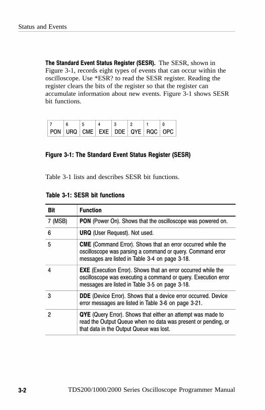
Status and Events
3−2 TDS200/1000/2000 Series Oscilloscope Programmer Manual
The Standard Event Status Register (SESR). The SESR, shown in Figure 3-1, records eight types of events that can occur within theoscilloscope. Use *ESR? to read the SESR register. Reading theregister clears the bits of the register so that the register canaccumulate information about new events. Figure 3-1 shows SESRbit functions.
PON URQ CME EXE DDE QYE RQC OPC
7 6 5 4 3 2 1 0
Figure 3−1: The Standard Event Status Register (SESR)
Table 3-1 lists and describes SESR bit functions.
Table 3−1: SESR bit functions
Bit Function
7 (MSB) PON (Power On). Shows that the oscilloscope was powered on.
6 URQ (User Request). Not used.
5 CME (Command Error). Shows that an error occurred while theoscilloscope was parsing a command or query. Command errormessages are listed in Table 3−4 on page 3−18.
4 EXE (Execution Error). Shows that an error occurred while theoscilloscope was executing a command or query. Execution errormessages are listed in Table 3−5 on page 3−18.
3 DDE (Device Error). Shows that a device error occurred. Deviceerror messages are listed in Table 3−6 on page 3−21.
2 QYE (Query Error). Shows that either an attempt was made toread the Output Queue when no data was present or pending, orthat data in the Output Queue was lost.

Status and Events
TDS200/1000/2000 Series Oscilloscope Programmer Manual 3−3
Table 3−1: SESR bit functions (Cont.)
Bit Function
1 RQC (Request Control). Not used.
0 (LSB) OPC (Operation Complete). Shows that the operation iscomplete. This bit is set when all pending operations completefollowing a *OPC command. See Table 2−25 on page 2−121 for alist of commands that generate an Operation Complete message.
The Status Byte Register (SBR). The SBR, shown in Figure 3-2, recordswhether output is available in the Output Queue, whether theoscilloscope requests service, and whether the SESR has recordedany events.
Use a Serial Poll (GPIB only) or *STB? to read the contents of theSBR. The bits in the SBR are set and cleared depending on thecontents of the SESR, the Event Status Enable Register (ESER), andthe Output Queue. When you use a Serial Poll to obtain the SBR, bit6 is the RQS bit. When you use the *STB? query to obtain the SBR,bit 6 is the MSS bit. Reading the SBR does not clear the bits. Figure 3-2 shows the SBR bit functions.
U
RQS
ESB MAV U U U U
MSS
7
6
5 4 3 2 1 0
6
Figure 3−2: The Status Byte Register (SBR)
Table 3-2 lists and describes SBR bit functions.

Status and Events
3−4 TDS200/1000/2000 Series Oscilloscope Programmer Manual
Table 3−2: SBR bit functions
Bit Function
7 (MSB) Not used.
6 RQS (Request Service), obtained from a serial poll. Shows thatthe oscilloscope requests service from the GPIB controller.
6 MSS (Master Status Summary), obtained from *STB?.Summarizes the ESB and MAV bits in the SBR.
5 ESB (Event Status Bit). Shows that status is enabled and presentin the SESR.
4 MAV (Message Available). Shows that output is available in theOutput Queue.
3 − 0 Not used.
Enable Registers
The DESER, ESER, and SRER allow you to select which events arereported to the Status Registers and the Event Queue. Each EnableRegister acts as a filter to a Status Register (the DESER also acts asa filter to the Event Queue) and can prevent information from beingrecorded in the register or queue.
Each bit in an Enable Register corresponds to a bit in the StatusRegister it controls. In order for an event to be reported to its bit inthe Status Register, the corresponding bit in the Enable Registermust be set to one. If the bit in the Enable Register is set to zero, theevent is not recorded.
The bits in the Enable Registers are set using various commands.The Enable Registers and the commands used to set them aredescribed below.
The Device Event Status Enable Register (DESER). The DESER, shownin Figure 3-3, controls which types of events are reported to theSESR and the Event Queue. The bits in the DESER correspond tothose in the SESR, as described earlier.

Status and Events
TDS200/1000/2000 Series Oscilloscope Programmer Manual 3−5
Use the DESE command to enable and disable the bits in theDESER. Use the DESE? query to read the DESER. Figure 3-3shows the DESER bit functions.
PON URQ CME EXE DDE QYE RQC OPC7 6 5 4 3 2 1 0
Figure 3−3: The Device Event Status Enable Register (DESER)
The Event Status Enable Register (ESER). The ESER controls whichtype of events are summarized by the Event Status Bit (ESB) in theSBR.
Use the *ESE command to set the bits in the ESER, and use the*ESE? query to read it. Figure 3-4 shows the ESER bit functions.
PON URQ CME EXE DDE QYE RQC OPC7 6 5 4 3 2 1 0
Figure 3−4: The Event Status Enable Register (ESER)
The Service Request Enable Register (SRER). The SRER controls whichbits in the SBR generate a Service REquest (GPIB only) and aresummarized by the Master Status Summary (MSS) bit.
Use the *SRE command to set the SRER. Use the *SRE? query toread it. The RQS bit remains set to one until either the Status ByteRegister is read by a Serial Poll (GPIB only) or the MSS bit changesback to a zero. Figure 3-5 shows the SRER bit functions.
U U ESB MAV U U U U7 6 5 4 3 2 1 0
Figure 3−5: The Service Request Enable Register (SRER)

Status and Events
3−6 TDS200/1000/2000 Series Oscilloscope Programmer Manual
The Enable Registers and the *PSC Command
The *PSC command controls the contents of the Enable Registers atpower on. Sending *PSC 1 sets the Enable Registers at power on asfollows:
� DESER 255 (equivalent to a DESe 255 command)
� ESER 0 (equivalent to an *ESE 0 command)
� SRER 0 (equivalent to an *SRE 0 command)
Sending *PSC 0 lets the Enable Registers maintain their values innonvolatile memory through a power cycle.
NOTE. To enable the PON (Power On) event to generate a ServiceRequest (GPIB only), send *PSC 0, use the DESe and *ESEcommands to enable PON in the DESER and ESER, and use the*SRE command to enable bit 5 in the SRER. Subsequent power-oncycles will generate a Service Request (GPIB only).
Queues
The oscilloscope status and event reporting system contains twoqueues: the Output Queue and the Event Queue.
The Output Queue
The Output Queue stores query responses waiting to be output. Theoscilloscope empties the Output Queue each time it receives a newcommand or query message. This means you must read any queryresponse before you send the next command or query, or you willlose responses to earlier queries. Also, an error may result.

Status and Events
TDS200/1000/2000 Series Oscilloscope Programmer Manual 3−7
NOTE. When a controller sends a query, an <EOM>, and a secondquery, the digitizing oscilloscope normally clears the first responseand outputs the second while reporting a Query Error (QYE bit in theESER) to indicate the lost response. A fast controller, however, mayreceive a part or all of the first response as well. To avoid thissituation, the controller should always read the response immediatelyafter sending any terminated query message or send a DCL (DeviceClear) before sending the second query.
The Event Queue
The Event Queue stores detailed information on up to 20 events. Ifmore than 20 events stack up in the Event Queue, the 20th event isreplaced by event code 350, “Too many events.”
Read the Event Queue with EVENT? (which returns only the eventnumber), with EVMsg? (which returns the event number and a textdescription of the event), or with ALLEV? (which returns all theevent numbers along with a description of the event). Reading anevent removes it from the queue.
Before reading an event from the Event Queue, you must use *ESR?to read the summary of the event from the SESR. This makes theevents summarized by *ESR? available to EVENT? and EVMSG?,and empties the SESR.
Reading the SESR erases any events that were summarized byprevious *ESR? reads but not read from the Event Queue. Eventsthat follow an *ESR? read are put in the Event Queue, but are notavailable until *ESR? is used again.

Status and Events
3−8 TDS200/1000/2000 Series Oscilloscope Programmer Manual
Event Handling Sequence
In this description, the numbers in parentheses map to the corre-sponding numbers in Figure 3-6.
When an event occurs, a signal is sent to the DESER (1). If that typeof event is enabled in the DESER (that is, if the bit for that eventtype is set to 1), the appropriate bit in the SESR is set to one and theevent is recorded in the Event Queue (2). If the corresponding bit inthe ESER is also enabled (3), then the ESB bit in the SBR is set toone (4).
When output is sent to the Output Queue, the MAV bit in the SBR isset to one (5).
When a bit in the SBR is set to one and the corresponding bit in theSRER is enabled (6), the MSS bit in the SBR is set to one and aservice request (GPIB only) is generated (7).
Figure 3-6 shows how to use the status and event handling system.

Status and Events
TDS200/1000/2000 Series Oscilloscope Programmer Manual 3−9
Device Event Status Enable Register(DESER)
Standard Event Status Register(SESR)
Event Status Enable Register(ESER)
Status Byte Register(SBR)
Service Request Enable Register(SRER)
EventQueue
OutputQueue
Event
Event
Event
Byte
Byte
Byte
1
2
3
4
67
5
PON URQ CME EXE DDE QYE RQC OPC7 6 5 4 3 2 1 0
PON URQ CME EXE DDE QYE RQC OPC7 6 5 4 3 2 1 0
PON URQ CME EXE DDE QYE RQC OPC7 6 5 4 3 2 1 0
U
RQS
ESB MAV U U U U
MSS
7
6
5 4 3 2 1 0
6
U U ESB MAV U U U U7 6 5 4 3 2 1 0
Read using DESE?Write using DESE
Read using *ESR?Cannot be written
Read using *ESE?Write using *ESE
Read using *STB?Cannot be written
Read using *SRE?Write using *SRE
Figure 3−6: Status and event handling process
Status and Events
3−10 TDS200/1000/2000 Series Oscilloscope Programmer Manual
Synchronization Methods
Although most commands are completed almost immediately afterbeing received by the oscilloscope, some commands start a processthat requires more time. For example, once a HARDCOPY STARTcommand is executed, it may be a few seconds before the hardcopyoperation is complete. Rather than remain idle while the operation isin process, the oscilloscope continues processing other commands.This means that some operations are not completed in the order thatthey were sent.
There may be times when the result of an operation is dependent onthe result of an earlier one, and you must be assured that the firstoperation has completed before processing the next one. The statusand event reporting system provides ways to do this.
For example, a typical application would be to acquire a single-se-quence waveform, and then take a measurement on the acquiredwaveform. You could use the following command sequence:
/** Set up single-sequence acquisition **/
SELECT:CH1 ON
ACQUIRE:MODE SAMPLE
ACQUIRE:STOPAFTER SEQUENCE
/** Acquire waveform data **/
ACQUIRE:STATE ON
/** Set up the measurement 2
MEASUREMENT:IMMED:TYPE PK2PK
MEASUREMENT:IMMED:SOURCE CH1
/** Take peak-to-peak measurement on acquired data **/
MEASUREMENT:IMMED:VALUE?
The acquisition of the waveform requires extended processing timeand may not complete before the amplitude measurement is taken.(See Figure 3-7.) This will result in an incorrect peak-to-peak value.

Status and Events
TDS200/1000/2000 Series Oscilloscope Programmer Manual 3−1 1
MEASUREMENT:IMMED:VALUE?
Processing Time
Acquiring Waveform Data
ACQUIRE:STATE ON
Figure 3−7: Command processing without using synchronization
The acquisition of the waveform must be completed before themeasurement can be taken on the acquired data. This is achieved bysynchronizing the program so that the measurement command is notprocessed by the oscilloscope until the acquisition is complete.Figure 3-8 shows the desired processing sequence.
MEASUREMENT:IMMED:VALUE?
Processing Time
Acquiring Waveform Data
ACQUIRE:STATE ON
Figure 3−8: Processing sequence with synchronization
Four commands can be used to synchronize the operation of theoscilloscope with your application program: *WAI, BUSY?, *OPC,and *OPC?. The *OPC? query is the most simple.
Using the *WAI Command
You can force commands to execute sequentially by using the *WAIcommand. This command forces completion of the previouscommands before processing new ones.

Status and Events
3−12 TDS200/1000/2000 Series Oscilloscope Programmer Manual
The same command sequence using the *WAI command forsynchronization follows:
/* Set up single-sequence acquisition */
SELECT:CH1 ON
ACQUIRE:MODE SAMPLE
ACQUIRE:STOPAFTER SEQUENCE
/* Acquire waveform data */
ACQUIRE:STATE ON
/* Set up the measurement parameters */
MEASUREMENT:IMMED:TYPE PK2PK
MEASUREMENT:IMMED:SOURCE CH1
/* Wait until the acquisition is complete before taking themeasurement */
*WAI
/* Take peak-to-peak measurement on acquired data */
MEASUREMENT:IMMED:VALUE?
Though *WAI is one of the easiest ways to achieve synchronization,it is also the most costly. The processing time of the oscilloscope isslowed, since it is processing a single command at a time. This timecould be spent doing other tasks.
The controller can continue to write commands to the input buffer,but the commands are not processed by the oscilloscope until alloperations in process are complete. If the input buffer becomes full,the controller will be unable to write any more commands to thebuffer and will result in a time out.
Status and Events
TDS200/1000/2000 Series Oscilloscope Programmer Manual 3−13
Using the BUSY Query
BUSY? allows you to find out whether the oscilloscope is busyprocessing a command that has an extended processing time, such assingle-sequence acquisition.
The same command sequence using BUSY? for synchronizationfollows:
/* Set up single-sequence acquisition */
SELECT:CH1 ON
ACQUIRE:MODE SAMPLE
ACQUIRE:STOPAFTER SEQUENCE
/* Acquire waveform data */
ACQUIRE:STATE ON
/* Set up the measurement parameters */
MEASUREMENT:IMMED:TYPE PK2PK
MEASUREMENT:IMMED:SOURCE CH1
/* Wait until the acquisition is complete before taking themeasurement */
While BUSY? keep looping
/* Take peak-to-peak measurement on acquired data */
MEASUREMENT:IMMED:VALUE?
This sequence lets you create your own wait loop rather than usingthe *WAI command. An advantage to using BUSY? is that youeliminate the possibility of a time out caused by writing too manycommands to the input buffer. The controller is still tied up, though,and the repeated BUSY? results in more bus traffic.

Status and Events
3−14 TDS200/1000/2000 Series Oscilloscope Programmer Manual
Using the *OPC Set Command
If the corresponding status registers are enabled, the *OPC commandsets the OPC bit in the Standard Event Status Register (SESR) whenan operation is complete. You can use this command in conjunctionwith either a serial poll or service request handler to achievesynchronization.
Serial Poll Method (GPIB Only). Enable the OPC bit in the Device EventStatus Enable Register (DESER) and the Event Status EnableRegister (ESER) using the DESE and *ESE commands. When theoperation is complete, the OPC bit in the Standard Event StatusRegister (SESR) is enabled, and the Event Status Bit (ESB) in theStatus Byte Register is enabled.
The same command sequence using the *OPC command forsynchronization with serial polling looks like this:
/* Set up single−sequence acquisition */
SELECT:CH1 ONACQUIRE:MODE SAMPLEACQUIRE:STOPAFTER SEQUENCE
/* Enable the status registers */
DESE 1*ESE 1*SRE 0
/* Acquire waveform data */
ACQUIRE:STATE ON
/* Set up the measurement parameters */
MEASUREMENT:IMMED:TYPE PK2PKMEASUREMENT:IMMED:SOURCE CH1
/* Wait until the acquisition is complete beforetaking the measurement */
*OPCWhile serial poll = 0, keep looping
/* Take peak−to−peak measurement on acquired data */
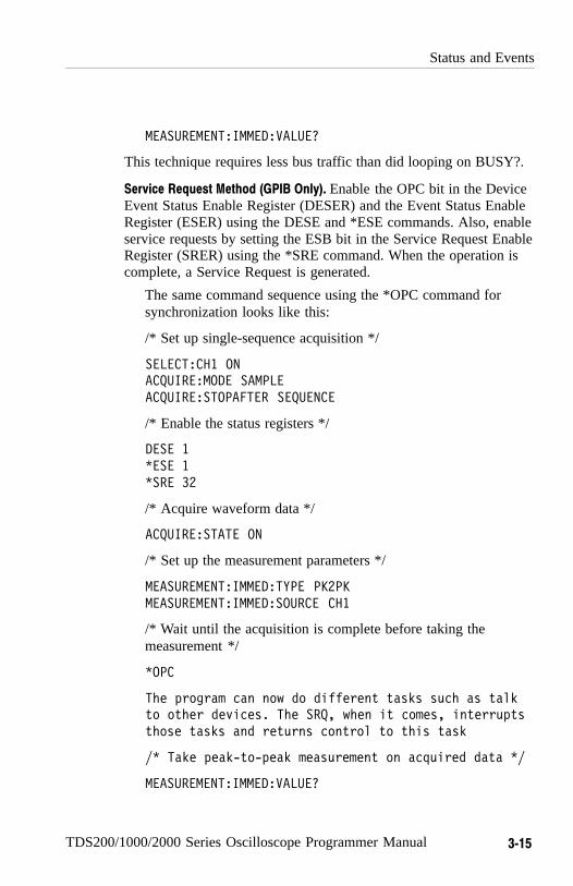
Status and Events
TDS200/1000/2000 Series Oscilloscope Programmer Manual 3−15
MEASUREMENT:IMMED:VALUE?
This technique requires less bus traffic than did looping on BUSY?.
Service Request Method (GPIB Only). Enable the OPC bit in the DeviceEvent Status Enable Register (DESER) and the Event Status EnableRegister (ESER) using the DESE and *ESE commands. Also, enableservice requests by setting the ESB bit in the Service Request EnableRegister (SRER) using the *SRE command. When the operation iscomplete, a Service Request is generated.
The same command sequence using the *OPC command forsynchronization looks like this:
/* Set up single-sequence acquisition */
SELECT:CH1 ONACQUIRE:MODE SAMPLEACQUIRE:STOPAFTER SEQUENCE
/* Enable the status registers */
DESE 1*ESE 1*SRE 32
/* Acquire waveform data */
ACQUIRE:STATE ON
/* Set up the measurement parameters */
MEASUREMENT:IMMED:TYPE PK2PKMEASUREMENT:IMMED:SOURCE CH1
/* Wait until the acquisition is complete before taking themeasurement */
*OPC
The program can now do different tasks such as talkto other devices. The SRQ, when it comes, interruptsthose tasks and returns control to this task
/* Take peak−to−peak measurement on acquired data */
MEASUREMENT:IMMED:VALUE?
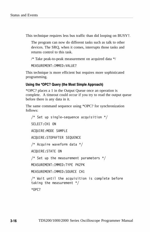
Status and Events
3−16 TDS200/1000/2000 Series Oscilloscope Programmer Manual
This technique requires less bus traffic than did looping on BUSY?.
The program can now do different tasks such as talk to otherdevices. The SRQ, when it comes, interrupts those tasks andreturns control to this task.
/* Take peak-to-peak measurement on acquired data */
MEASUREMENT:IMMED:VALUE?
This technique is more efficient but requires more sophisticatedprogramming.
Using the *OPC? Query (the Most Simple Approach)
*OPC? places a 1 in the Output Queue once an operation iscomplete. A timeout could occur if you try to read the output queuebefore there is any data in it.
The same command sequence using *OPC? for synchronizationfollows:
/* Set up single−sequence acquisition */
SELECT:CH1 ON
ACQUIRE:MODE SAMPLE
ACQUIRE:STOPAFTER SEQUENCE
/* Acquire waveform data */
ACQUIRE:STATE ON
/* Set up the measurement parameters */
MEASUREMENT:IMMED:TYPE PK2PK
MEASUREMENT:IMMED:SOURCE CH1
/* Wait until the acquisition is complete beforetaking the measurement */
*OPC?

Status and Events
TDS200/1000/2000 Series Oscilloscope Programmer Manual 3−17
Wait for read from Output Queue.
/* Take peak−to−peak measurement on acquired data */
MEASUREMENT:IMMED:VALUE?
Using *OPC? synchronization is the simplest approach. It requiresno status handling or loops. However, you must set the controllertime out for longer than the acquisition operation.
Messages
Tables 3-3 through 3-9 list all the programming interface messagesthe oscilloscope generates in response to commands and queries.
Each message is the result of an event. Each type of event sets aspecific bit in the SESR and is controlled by the equivalent bit inthe DESER. Thus, each message is associated with a specific SESRbit. In the message tables that follow, the associated SESR bit isspecified in the table title, with exceptions noted with the errormessage text.
Table 3-3 shows the messages when the system has no events orstatus to report. These have no associated SESR bit.
Table 3−3: No event messages
Code Message
0 No events to report : queue empty
1 No events to report : new events pending *ESR?
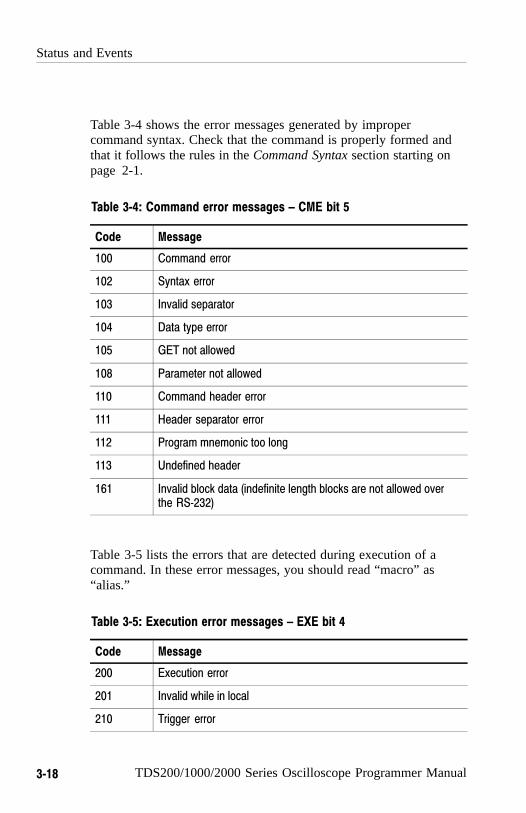
Status and Events
3−18 TDS200/1000/2000 Series Oscilloscope Programmer Manual
Table 3-4 shows the error messages generated by impropercommand syntax. Check that the command is properly formed andthat it follows the rules in the Command Syntax section starting onpage 2-1.
Table 3−4: Command error messages – CME bit 5
Code Message
100 Command error
102 Syntax error
103 Invalid separator
104 Data type error
105 GET not allowed
108 Parameter not allowed
110 Command header error
111 Header separator error
112 Program mnemonic too long
113 Undefined header
161 Invalid block data (indefinite length blocks are not allowed overthe RS−232)
Table 3-5 lists the errors that are detected during execution of acommand. In these error messages, you should read “macro” as“alias.”
Table 3−5: Execution error messages – EXE bit 4
Code Message
200 Execution error
201 Invalid while in local
210 Trigger error
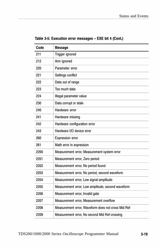
Status and Events
TDS200/1000/2000 Series Oscilloscope Programmer Manual 3−19
Table 3−5: Execution error messages – EXE bit 4 (Cont.)
Code Message
211 Trigger ignored
212 Arm ignored
220 Parameter error
221 Settings conflict
222 Data out of range
223 Too much data
224 Illegal parameter value
230 Data corrupt or stale
240 Hardware error
241 Hardware missing
242 Hardware configuration error
243 Hardware I/O device error
260 Expression error
261 Math error in expression
2200 Measurement error, Measurement system error
2201 Measurement error, Zero period
2202 Measurement error, No period found
2203 Measurement error, No period, second waveform
2204 Measurement error, Low signal amplitude
2205 Measurement error, Low amplitude, second waveform
2206 Measurement error, Invalid gate
2207 Measurement error, Measurement overflow
2208 Measurement error, Waveform does not cross Mid Ref
2209 Measurement error, No second Mid Ref crossing

Status and Events
3−20 TDS200/1000/2000 Series Oscilloscope Programmer Manual
Table 3−5: Execution error messages – EXE bit 4 (Cont.)
Code Message
2210 Measurement error, No Mid Ref crossing, second waveform
2211 Measurement error, No backwards Mid Ref crossing
2212 Measurement error, No negative crossing
2213 Measurement error, No positive crossing
2214 Measurement error, No crossing
2215 Measurement error, No crossing, second waveform
2216 Measurement error, No crossing, target waveform
2217 Measurement error, Constant waveform
2218 Measurement error, Unused
2219 Measurement error, No valid edge: No arm sample
2220 Measurement error, No valid edge: No arm cross
2221 Measurement error, No valid edge: No trigger cross
2222 Measurement error, No valid edge: No second cross
2223 Measurement error, waveform mismatch
2224 Measurement error, WAIT calculating
2225 Measurement error, No waveform to measure
2226 Null Waveform
2227 Positive and Negative Clipping
2228 Measurement error, Positive Clipping
2229 Measurement error, Negative Clipping
2230 Measurement error, High Ref < Low Ref
2235 Math error, Invalid math description
2241 Waveform request is invalid
2242 Data start > record length
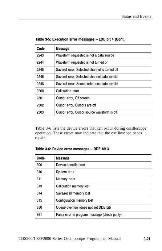
Status and Events
TDS200/1000/2000 Series Oscilloscope Programmer Manual 3−21
Table 3−5: Execution error messages – EXE bit 4 (Cont.)
Code Message
2243 Waveform requested is not a data source
2244 Waveform requested is not turned on
2245 Saveref error, Selected channel is turned off
2246 Saveref error, Selected channel data invalid
2248 Saveref error, Source reference data invalid
2260 Calibration error
2301 Cursor error, Off screen
2302 Cursor error, Cursors are off
2303 Cursor error, Cursor source waveform is off
Table 3-6 lists the device errors that can occur during oscilloscopeoperation. These errors may indicate that the oscilloscope needsrepair.
Table 3−6: Device error messages – DDE bit 3
Code Message
300 Device−specific error
310 System error
311 Memory error
313 Calibration memory lost
314 Save/recall memory lost
315 Configuration memory lost
350 Queue overflow (does not set DDE bit)
361 Parity error in program message (check parity)
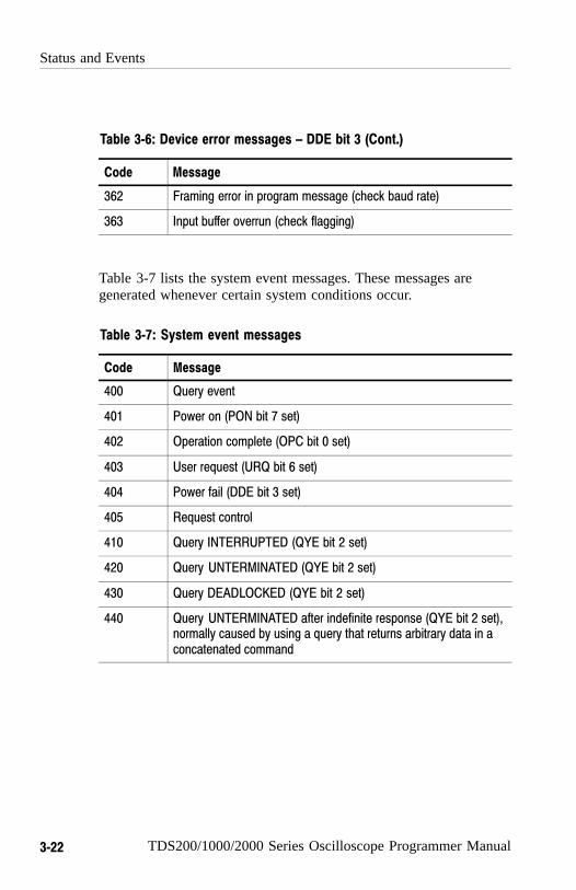
Status and Events
3−22 TDS200/1000/2000 Series Oscilloscope Programmer Manual
Table 3−6: Device error messages – DDE bit 3 (Cont.)
Code Message
362 Framing error in program message (check baud rate)
363 Input buffer overrun (check flagging)
Table 3-7 lists the system event messages. These messages aregenerated whenever certain system conditions occur.
Table 3−7: System event messages
Code Message
400 Query event
401 Power on (PON bit 7 set)
402 Operation complete (OPC bit 0 set)
403 User request (URQ bit 6 set)
404 Power fail (DDE bit 3 set)
405 Request control
410 Query INTERRUPTED (QYE bit 2 set)
420 Query UNTERMINATED (QYE bit 2 set)
430 Query DEADLOCKED (QYE bit 2 set)
440 Query UNTERMINATED after indefinite response (QYE bit 2 set),normally caused by using a query that returns arbitrary data in aconcatenated command
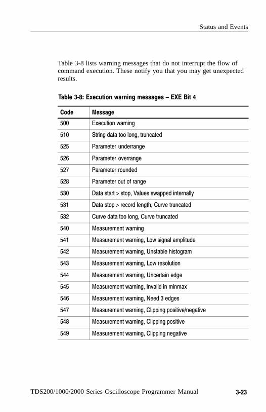
Status and Events
TDS200/1000/2000 Series Oscilloscope Programmer Manual 3−23
Table 3-8 lists warning messages that do not interrupt the flow ofcommand execution. These notify you that you may get unexpectedresults.
Table 3−8: Execution warning messages – EXE Bit 4
Code Message
500 Execution warning
510 String data too long, truncated
525 Parameter underrange
526 Parameter overrange
527 Parameter rounded
528 Parameter out of range
530 Data start > stop, Values swapped internally
531 Data stop > record length, Curve truncated
532 Curve data too long, Curve truncated
540 Measurement warning
541 Measurement warning, Low signal amplitude
542 Measurement warning, Unstable histogram
543 Measurement warning, Low resolution
544 Measurement warning, Uncertain edge
545 Measurement warning, Invalid in minmax
546 Measurement warning, Need 3 edges
547 Measurement warning, Clipping positive/negative
548 Measurement warning, Clipping positive
549 Measurement warning, Clipping negative
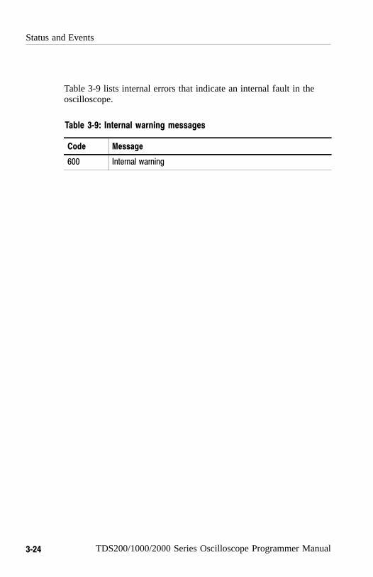
Status and Events
3−24 TDS200/1000/2000 Series Oscilloscope Programmer Manual
Table 3-9 lists internal errors that indicate an internal fault in theoscilloscope.
Table 3−9: Internal warning messages
Code Message
600 Internal warning

Programming Example


TDS200/1000/2000 Series Oscilloscope Programmer Manual 4−1
Programming Example
The following series of commands and queries illustrate many of themost common commands and techniques.
To use these commands and queries over RS232, you will need touse a communications program on your computer, such as tip in theUnix environment, or Hyperterminal in the Microsoft Windowsenvironment.
To use these commands and queries over GPIB, you will need to usea program or routines that interface to the GPIB hardware in yourcomputer. This software is usually supplied by the GPIB hardwaremanufacturer.
In these examples, data sent from the controller computer to theoscilloscope is prefaced with the > symbol. Replies from theoscilloscope have no preface.
> rem "Check for any messages, and clear them from the queue."> *esr?128> allev?:ALLEV 401,"Power on; "
> rem "Set the scope to the default state."> factory
> rem "Set the scope parameters that differ from the defaults."> ch1:volts 2.0> hor:main:scale 100e−6> trig:main:level 2.4
> rem "Start a single sequence acquisition."> acquire:stopafter sequence> acquire:state on> rem "Wait for the acquisition to complete."> rem "Note: your controller program time−out must be set longenough to handle the wait."> *opc?1

Programming Example
4−2 TDS200/1000/2000 Series Oscilloscope Programmer Manual
> rem "Use the oscilloscope built−in measurements to measure thewaveform you acquired."> measu:immed:type mean> measu:immed:value?:MEASUREMENT:IMMED:VALUE 2.4631931782E0
> rem "Be sure to use the *esr? query to check for measurementerrors."> measu:immed:type freq> Measu:immed:value?:MEASUREMENT:IMMED:VALUE 9.9E37> *esr?16> allev?:ALLEV 2202,"Measurement error, No period found; "
> rem "Query out the waveform points, for later analysis on yourcontroller computer."> data:encdg ascii> curve?:CURVE 7,6,5,5,5,6,6,6,8 [...]
> rem "Query out the parameters used for caculating the times andvoltages of the waveform points."> wfmpre?:WFMPRE:BYT_NR 1;BIT_NR 8;ENCDG ASC;BN_FMT RP;BYT_OR MSB;NR_PT2500; [...]

Appendices


TDS200/1000/2000 Series Oscilloscope Programmer Manual A−1
Appendix A: ASCII Code Chart
0 1 2 3 4 5 6 7
0 0
NUL0 0
20
DLE10 16
40
SP20 32
60
030 48
100
@40 64
120
P50 80
140
60 96
160
p70 112
1 1
SOH1 1
21
DC111 17
41
!21 33
61
131 49
101
A41 65
121
Q51 81
141
a61 97
161
q71 113
2 2
STX2 2
22
DC212 18
42
22 34
”62
232 50
102
B42 66
122
R52 82
142
b62 98
162
r72 114
3 3
ETX3 3
23
DC313 19
43
#23 35
63
333 51
103
C43 67
123
S53 83
143
c63 99
163
s73 115
4 4
EOT4 4
24
DC414 20
44
$24 36
64
434 52
104
D44 68
124
T54 84
144
d64 100
164
t74 116
5 5
ENQ5 5
25
NAK15 21
45
%25 37
65
535 53
105
E45 69
125
U55 85
145
e65 101
165
u75 117
6 6
ACK6 6
26
SYN16 22
46
&26 38
66
636 54
106
F46 70
126
V56 86
146
f66 102
166
v76 118
7 7
BEL7 7
27
ETB17 23
47
27 39
’67
737 55
107
G47 71
127
W57 87
147
g67 103
167
w77 119
8 10
BS8 8
30
CAN18 24
50
(28 40
70
838 56
110
H48 72
130
X58 88
150
h68 104
170
x78 120
9 11
HT9 9
31
EM19 25
51
)29 41
71
939 57
111
I49 73
131
Y59 89
151
i69 105
171
y79 121
Continued on next page
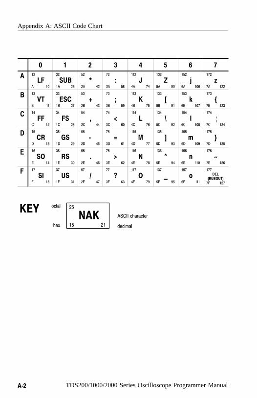
Appendix A: ASCII Code Chart
A−2 TDS200/1000/2000 Series Oscilloscope Programmer Manual
76543210
A 12
LFA 10
32
SUB1A 26
52
*2A 42
72
:3A 58
112
J4A 74
132
Z5A 90
152
j6A 106
172
z7A 122
B 13
VTB 11
33
ESC1B 27
53
+2B 43
73
;3B 59
113
K4B 75
133
[5B 91
153
k6B 107
173
{7B 123
C 14
FFC 12
34
FS1C 28
54
,2C 44
74
<3C 60
114
L4C 76
134
\5C 92
154
l6C 108
174
7C 124
D 15
CRD 13
35
GS1D 29
55
−2D 45
75
=3D 61
115
M4D 77
135
]5D 93
155
m6D 109
175
}7D 125
E 16
SOE 14
36
RS1E 30
56
.2E 46
76
>3E 62
116
N4E 78
136
^5E 94
156
n6E 110
176
~7E 126
F 17
SIF 15
37
US1F 31
57
/2F 47
77
?3F 63
117
O4F 79
137
_
5F 95
157
o6F 111
177DEL
(RUBOUT)7F 127
25
NAK15 21hex
octal
decimal
ASCII characterKEY

TDS200/1000/2000 Series Oscilloscope Programmer Manual B−1
Appendix B: Factory Setup
The following listing is the instrument response to the concatenatedcommand FACtory;SET?. This response describes the factory defaultsetup in detail. (Carriage returns have been inserted for clarity.)
Items enclosed in ( ) parentheses are returned by the SET? queryresponse, but are not changed by the FACtory command.
TDS1000− and 2000−Series Oscilloscopes
Responses for channel 3 and 4 apply only to 4-channel models.
:HEADER 1;(:VERBOSE 1;)
:DATA:ENCDG RIBINARY;DESTINATION REFA;SOURCE CH1;START1;STOP 2500;WIDTH 1;
(:LOCK NONE;)
:DISPLAY:FORMAT YT;STYLE VECTORS;PERSISTENCE 0;(CONTRAST50);(INVERT OFF);
:ACQUIRE:MODE SAMPLE;NUMAVG 16;STATE 1;STOPAFTERRUNSTOP;
:CH1:PROBE 10;SCALE 1.0E0;POSITION 0.0E0;COUPLINGDC;BANDWIDTH OFF;INVERT OFF;
:CH2:PROBE 10;SCALE 1.0E0;POSITION 0.0E0;COUPLINGDC;BANDWIDTH OFF;INVERT OFF;
:CH3:PROBE 10;SCALE 1.0E0;POSITION 0.0E0;COUPLINGDC;BANDWIDTH OFF;INVERT OFF;
:CH4:PROBE 10;SCALE 1.0E0;POSITION 0.0E0;COUPLINGDC;BANDWIDTH OFF;INVERT OFF;
:HORIZONTAL:VIEW MAIN;MAIN:SCALE 5.0E−4;POSITION0.0E0;:HORIZONTAL:DELAY:SCALE 5.0E−5;POSITION 0.0E0;
:TRIGGER:MAIN:MODE AUTO;TYPE EDGE;HOLDOFF:VALUE5.0E−7;:TRIGGER:MAIN:EDGE:SOURCE CH1;COUPLING
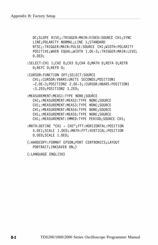
Appendix B: Factory Setup
B−2 TDS200/1000/2000 Series Oscilloscope Programmer Manual
DC;SLOPE RISE;:TRIGGER:MAIN:VIDEO:SOURCE CH1;SYNCLINE;POLARITY NORMAL;LINE 1;STANDARDNTSC;:TRIGGER:MAIN:PULSE:SOURCE CH1;WIDTH:POLARITYPOSITIVE;WHEN EQUAL;WIDTH 1.0E−3;:TRIGGER:MAIN:LEVEL0.0E0;
:SELECT:CH1 1;CH2 0;CH3 0;CH4 0;MATH 0;REFA 0;REFB0;REFC 0;REFD 0;
:CURSOR:FUNCTION OFF;SELECT:SOURCECH1;:CURSOR:VBARS:UNITS SECONDS;POSITION1−2.0E−3;POSITION2 2.0E−3;:CURSOR:HBARS:POSITION1−3.2E0;POSITION2 3.2E0;
:MEASUREMENT:MEAS1:TYPE NONE;SOURCECH1;:MEASUREMENT:MEAS2:TYPE NONE;SOURCECH1;:MEASUREMENT:MEAS3:TYPE NONE;SOURCECH1;:MEASUREMENT:MEAS4:TYPE NONE;SOURCECH1;:MEASUREMENT:MEAS5:TYPE NONE;SOURCECH1;:MEASUREMENT:IMMED:TYPE PERIOD;SOURCE CH1;
:MATH:DEFINE "CH1 − CH2";FFT:HORIZONTAL:POSITION5.0E1;SCALE 1.0E0;:MATH:FFT:VERTICAL:POSITION0.0E0;SCALE 1.0E0;
(:HARDCOPY:FORMAT EPSON;PORT CENTRONICS;LAYOUTPORTRAIT;INKSAVER ON;)
(:LANGUAGE ENGLISH)

Appendix B: Factory Setup
TDS200/1000/2000 Series Oscilloscope Programmer Manual B−3
TDS210 and TDS220 Oscilloscopes
Items enclosed in < > brackets are present only when the TDS2MMmodule is installed.
:HEADER 1;(:VERBOSE 1;)
:DATA:ENCDG RIBINARY;DESTINATION REFA;SOURCE CH1;START 1;STOP 2500;WIDTH 1;
(:LOCK NONE;)
:DISPLAY:FORMAT YT;STYLE VECTORS;PERSISTENCE 0;CONTRAST 50;
:ACQUIRE:MODE SAMPLE;NUMAVG 16;STATE 1;STOPAFTER RUNSTOP;
:CH1:PROBE 10;SCALE 1.0E0;POSITION 0.0E0;COUPLING DC;BANDWIDTH OFF;<INVERT OFF;>
:CH2:PROBE 10;SCALE 1.0E0;POSITION 0.0E0;COUPLING DC;BANDWIDTH OFF;<INVERT OFF;>
:HORIZONTAL:VIEW MAIN;MAIN:SCALE 5.0E−4;POSITION 0.0E0;:HORIZONTAL:DELAY:SCALE 5.0E−5;POSITION 0.0E0;
:TRIGGER:MAIN:MODE AUTO;TYPE EDGE;HOLDOFF:VALUE 5.0E−7;:TRIGGER:MAIN:EDGE:SOURCE CH1;COUPLING DC;SLOPE RISE;:TRIGGER:MAIN:VIDEO:SOURCE CH1;SYNC LINE;POLARITY NORMAL;:TRIGGER:MAIN:LEVEL 0.0E0;
:SELECT:CH1 1;CH2 0;MATH 0;REFA 0;REFB 0;
:CURSOR:FUNCTION OFF;SELECT:SOURCE CH1;:CURSOR:VBARS:UNITS SECONDS;POSITION1 −2.0E−3; POSITION2 2.0E−3;:CURSOR:HBARS:POSITION1 −3.2E0; POSITION2 3.2E0;
:MEASUREMENT:MEAS1:TYPE NONE;SOURCE CH1;:MEASUREMENT:MEAS2:TYPE NONE;SOURCE CH1;:MEASUREMENT:MEAS3:TYPE NONE;SOURCE CH1;:MEASUREMENT:MEAS4:TYPE NONE;SOURCE CH1;:MEASUREMENT:IMMED:TYPE PERIOD;SOURCE CH1;

Appendix B: Factory Setup
B−4 TDS200/1000/2000 Series Oscilloscope Programmer Manual
:MATH:DEFINE "CH1 + CH2";<FFT:HORIZONTAL:POSITION 5.0E1;SCALE 1.0E0;><:MATH:FFT:VERTICAL:POSITION 0.0E0;SCALE 1.0E0;>
(:HARDCOPY:FORMAT EPSON;PORT CENTRONICS;LAYOUT PORTRAIT;)
(:LANGUAGE ENGLISH)
TDS224 Oscilloscopes
Items enclosed in < > brackets are present only when the TDS2MMmodule is installed.
:HEADER 1;(:VERBOSE 1;)
:DATA:ENCDG RIBINARY;DESTINATION REFA;SOURCE CH1;START 1;STOP 2500;WIDTH 1;
(:LOCK NONE;)
:DISPLAY:FORMAT YT;STYLE VECTORS;PERSISTENCE 0;CONTRAST 50;
:ACQUIRE:MODE SAMPLE;NUMAVG 16;STATE 1;STOPAFTER RUNSTOP;
:CH1:PROBE 10;SCALE 1.0E0;POSITION 0.0E0;COUPLING DC;BANDWIDTH OFF;INVERT OFF;
:CH2:PROBE 10;SCALE 1.0E0;POSITION 0.0E0;COUPLING DC;BANDWIDTH OFF;INVERT OFF;
:CH3:PROBE 10;SCALE 1.0E0;POSITION 0.0E0;COUPLING DC;BANDWIDTH OFF;INVERT OFF;
:CH4:PROBE 10;SCALE 1.0E0;POSITION 0.0E0;COUPLING DC;BANDWIDTH OFF;INVERT OFF;
:HORIZONTAL:VIEW MAIN;MAIN:SCALE 5.0E−4;POSITION 0.0E0;:HORIZONTAL:DELAY:SCALE 5.0E−5;POSITION 0.0E0;
:TRIGGER:MAIN:MODE AUTO;TYPE EDGE;HOLDOFF:VALUE 5.0E−7;:TRIGGER:MAIN:EDGE:SOURCE CH1;COUPLING DC;

Appendix B: Factory Setup
TDS200/1000/2000 Series Oscilloscope Programmer Manual B−5
SLOPE RISE;:TRIGGER:MAIN:VIDEO:SOURCE CH1;SYNC LINE;POLARITY NORMAL;:TRIGGER:MAIN:LEVEL 0.0E0;
:SELECT:CH1 1;CH2 0;CH3 0;CH4 0;MATH 0;REFA 0;REFB 0;REFC 0;REFD 0;
:CURSOR:FUNCTION OFF;SELECT:SOURCE CH1;
:CURSOR:VBARS:UNITS SECONDS;POSITION1 −2.0E−3;POSITION2 2.0E−3;:CURSOR:HBARS:POSITION1 −3.2E0;POSITION2 3.2E0;
:MEASUREMENT:MEAS1:TYPE NONE;SOURCE CH1;:MEASUREMENT:MEAS2:TYPE NONE;SOURCE CH1;:MEASUREMENT:MEAS3:TYPE NONE;SOURCE CH1;:MEASUREMENT:MEAS4:TYPE NONE;SOURCE CH1;:MEASUREMENT:IMMED:TYPE PERIOD;SOURCE CH1;
:MATH:DEFINE "CH1 − CH2";<FFT:HORIZONTAL:POSITION 5.0E1;SCALE 1.0E0;><:MATH:FFT:VERTICAL:POSITION 0.0E0;SCALE 1.0E0;>
(:HARDCOPY:FORMAT EPSON;PORT CENTRONICS;LAYOUT PORTRAIT;)
(:LANGUAGE ENGLISH)

Appendix B: Factory Setup
B−6 TDS200/1000/2000 Series Oscilloscope Programmer Manual

Glossary and Index

TDS200/1000/2000 Series Oscilloscope Programmer Manual Glossary−1
Glossary
ASCIIAcronym for the American Standard Code for InformationInterchange. Controllers transmit commands to the digitizingoscilloscope using ASCII character encoding.
AddressA 7-bit code that identifies an instrument on the communicationbus. The digitizing oscilloscope must have a unique address forthe controller to recognize and transmit commands to it.
Backus-Naur Form (BNF)A standard notation system for command syntax. The syntax inthis manual use BNF notation.
ControllerA computer or other device that sends commands to and acceptsresponses from the digitizing oscilloscope.
EOIA mnemonic referring to the control line “End or Identify” onthe GPIB interface bus. One of the two possible end-of-messageterminators.
EOMA generic acronym referring to the end-of-message terminator.The end-of-message terminator is either an EOI or the ASCIIcode for line feed (LF).
IEEEAcronym for the Institute of Electrical and ElectronicsEngineers.
RS-232A serial, full-duplex, asynchronous communication port thatfollows ANSI/EIA/TIA-562-1989[1], ANSI/EIA/TIA-574-1990[2], and CCITT V.24-1989[3] standards.
Glossary
Glossary−2 TDS200/1000/2000 Series Oscilloscope Programmer Manual
Serial PollA device (such as an oscilloscope) on the GPIB bus can requestservice from the GPIB Controller by asserting the GPIB SRQline (a Hardware line that is only present on the GPIBcommunications bus). When a controller achnowledges theSRQ, it ”serial polls” each open device on the bus to determinewhich device on the bus requested service. Any devicerequesting service returns a status byte with bit 6 set and thenunasserts the SRQ line. Devices not requiring service return astatus byte with bit 6 cleared.
TDS200/1000/2000 Series Oscilloscope Programmer Manual Index−1
Index
AAbbreviating, commands, 2-5ACQUIRE?, 2-35ACQUIRE:MODE, 2-36ACQUIRE:NUMACQ?, 2-37ACQUIRE:NUMAVG, 2-38ACQUIRE:STATE, 2-39ACQUIRE:STOPAFTER, 2-40Acquisition command group, 2-15Acquisition commands
ACQUIRE?, 2-35ACQUIRE:MODE, 2-36ACQUIRE:NUMACQ?, 2-37ACQUIRE:NUMAVG, 2-38ACQUIRE:STATE, 2-39ACQUIRE:STOPAFTER, 2-40
Address, Tektronix, viiALLEV?, 2-41Argument, command, 2-3ASCII, 2-1, A-1AUTOSET, 2-42AUTOSET:SIGNAL, 2-43AUTOSET:VIEW, 2-44
BBlock, command argument, 2-12BNF (Backus-Naur form), 2-1Break signal, 2-5BUSY?, 2-45, 3-13
C*CAL?, 2-46CALIBRATE:ABORT, 2-47CALIBRATE:CONTINUE, 2-47
CALIBRATE:FACTORY, 2-48CALIBRATE:INTERNAL, 2-49CALIBRATE:STATUS?, 2-49Calibration and diagnostic com-
mand group, 2-15Calibration and diagnostic com-
mands*CAL?, 2-46CALIBRATE:ABORT, 2-47CALIBRATE:CONTINUE, 2-47CALIBRATE:FACTORY, 2-48CALIBRATE:INTERNAL, 2-49CALIBRATE:STATUS?, 2-49DIAG:RESULT:FLAG?, 2-76DIAG:RESULT:LOG?, 2-77ERRORLOG:FIRST?, 2-81ERRORLOG:NEXT?, 2-82
CH<x>, command mnemonic, 2-8CH<x>?, 2-50CH<x>:BANDWIDTH, 2-50CH<x>:COUPLING, 2-52CH<x>:INVERT, 2-52CH<x>:POSITION, 2-53CH<x>:PROBE, 2-54CH<x>:SCALE, 2-55CH<x>:VOLTS, 2-56Channel, command mnemonic, 2-8Clear status, 2-56*CLS, 2-56Command
abbreviating, 2-5argument, 2-3block argument, 2-12BUSY?, 3-13common, 2-21, 2-24concatenating, 2-6definition, 2-4header, 2-2

Index
Index−2 TDS200/1000/2000 Series Oscilloscope Programmer Manual
message, 2-2mnemonic, 2-2*OPC, 3-14query, 2-2separator, 2-3set, 2-2synchronizing, 3-10syntax, BNF (Backus-Naur
form), 2-1*WAI, 3-11
Command argumentnumeric, 2-10quoted string, 2-11
Command entry rules, 2-5Command group
acquisition, 2-15calibration and diagnostic, 2-15cursor, 2-16display, 2-17hardcopy, 2-18horizontal, 2-18math, 2-19measurement, 2-20miscellaneous, 2-21RS-232, 2-22save and recall, 2-23status and error, 2-24trigger, 2-25vertical, 2-26waveform, 2-27
Command mnemonicCH<x>, 2-8channel, 2-8MEAS<x>, 2-9measurement specifier, 2-9REF<x>, 2-9reference waveform, 2-9waveform, 2-9<wfm>, 2-9
Command syntax, BNF (Backus-Naur form), 2-1
Common command, 2-24Common GPIB commands
*CAL?, 2-46CALIBRATE:CONTINUE, 2-47CALIBRATE:FACTORY, 2-48CALIBRATE:INTERNAL, 2-49CALIBRATE:STATUS?, 2-49*CLS, 2-56
communications modules, refer-ences to, vi
Concatenating, commands, 2-6Configuration, command query,
2-103Cursor command group, 2-16Cursor commands
CURSOR?, 2-57CURSOR:FUNCTION, 2-57CURSOR:HBARS?, 2-58CURSOR:HBARS:DELTA?,
2-59CURSOR:HBARS:POSI -
TION<x>, 2-59CURSOR:HBARS:UNITS?,
2-61CURSOR:SELECT:SOURCE,
2-61CURSOR:VBARS?, 2-62CURSOR:VBARS:DELTA?,
2-62CURSOR:VBARS:POSI -
TION<x>, 2-63CURSOR:VBARS:UNITS, 2-64
CURSOR?, 2-57CURSOR:FUNCTION, 2-57CURSOR:HBARS?, 2-58CURSOR:HBARS:DELTA?, 2-59CURSOR:HBARS:POSITION<x>,
2-59CURSOR:HBARS:UNITS?, 2-61CURSOR:SELECT:SOURCE,
2-61

Index
TDS200/1000/2000 Series Oscilloscope Programmer Manual Index−3
CURSOR:VBARS?, 2-62CURSOR:VBARS:DELTA?, 2-62CURSOR:VBARS:POSITION<x>,
2-63CURSOR:VBARS:UNITS, 2-64CURVE, 2-65
DDATA, 2-67DATA:DESTINATION, 2-68DATA:ENCDG, 2-68DATA:SOURCE, 2-70DATA:START, 2-71DATA:STOP, 2-72DATA:TARGET, 2-73DATA:WIDTH, 2-73DCL, 2-5, 3-7*DDT, 2-74DESE command, 2-75, 3-5DESER register, 2-75, 2-122, 3-4Device clear, 2-5DIAG:RESULT:FLAG?, 2-76DIAG:RESULT:LOG?, 2-77Display command group, 2-17Display commands
DISPLAY?, 2-77DISPLAY:CONTRAST, 2-78DISPLAY:FORMAT, 2-78DISPLAY:INVERT, 2-79DISPLAY:PERSISTENCE, 2-80DISPLAY:STYLE, 2-81
DISPLAY?, 2-77DISPLAY:CONTRAST, 2-78DISPLAY:FORMAT, 2-78DISPLAY:INVERT, 2-79DISPLAY:PERSISTENCE, 2-80DISPLAY:STYLE, 2-81
EEntering commands, 2-5Entering incorrect numeric argu-
ments, 2-10EOM (end of message), 2-8Error message, programming
interface, 3-17ERRORLOG:FIRST?, 2-81ERRORLOG:NEXT?, 2-82*ESE, 2-82, 3-5ESER register, 2-82, 2-122, 3-5*ESR?, 2-84*ESR? query, 3-2Event handling, 3-1Event query, 2-84, 2-85Event queue, 2-84, 2-85, 3-7Event queue sequence, 3-8EVENT?, 2-84EVMSG?, 2-85EVQTY?, 2-86Examples
block argument, 2-13Programming, 4-1quoted strings, 2-12
FFACTORY, 2-86Factory setup, detailed description,
B-3
GGPIB, EOM (end of message), 2-8

Index
Index−4 TDS200/1000/2000 Series Oscilloscope Programmer Manual
HHard copy commands
HARDCOPY, 2-88HARDCOPY:FORMAT, 2-89HARDCOPY:INKSAVER , 2-91HARDCOPY:LAYOUT, 2-91HARDCOPY:PORT, 2-92
HARDCOPY, 2-88Hardcopy command group, 2-18HARDCOPY:FORMAT, 2-89HARDCOPY:INKSAVER , 2-91HARDCOPY:LAYOUT, 2-91HARDCOPY:PORT, 2-92HDR, 2-93HEADER, 2-93Header
command, 2-2, 2-93included in query response, 2-93,
2-156Headers, in query responses, 2-4Horizontal command group, 2-18Horizontal commands
HORIZONTAL?, 2-94HORIZONTAL:DELAY?, 2-95HORIZONTAL:DELAY:POSI-
TION, 2-95, 2-98, 2-99HORIZONTAL:DELAY:SCALE,
2-96HORIZONTAL:DELAY:
SECDIV, 2-97HORIZONTAL:MAIN?, 2-97HORIZONTAL:MAIN:SCALE,
2-98HORIZONTAL:MAIN:SECDIV,
2-99HORIZONTAL:RECORD-
LENGTH, 2-100HORIZONTAL:SCALE, 2-100HORIZONTAL:SECDIV, 2-101
HORIZONTAL:TRIGGER:POSITION, 2-101
MATH:FFT:HORIZONTAL:POSITION, 2-108
MATH:FFT:HORIZONTAL:SCALE, 2-109
HORIZONTAL?, 2-94HORIZONTAL:DELAY?, 2-95HORIZONTAL:DELAY:
POSITION, 2-95, 2-98, 2-99HORIZONTAL:DELAY:SCALE,
2-96HORIZONTAL:DELAY:SECDIV,
2-97HORIZONTAL:MAIN?, 2-97HORIZONTAL:MAIN:SCALE,
2-98HORIZONTAL:MAIN:SECDIV,
2-99HORIZONTAL:RECORD-
LENGTH, 2-100HORIZONTAL:SCALE, 2-100HORIZONTAL:SECDIV, 2-101HORIZONTAL:TRIGGER:
POSITION, 2-101
IID?, 2-102*IDN?, 2-103IEEE Std. 488.2-1987, 2-1, 2-21,
2-24
LLANGUAGE, 2-104LOCK, 2-104*LRN?, 2-105

Index
TDS200/1000/2000 Series Oscilloscope Programmer Manual Index−5
MManual trigger, simulation with
command, 2-137Math command group, 2-19MATH?, 2-105MATH:DEFINE, 2-106MATH:FFT:HORIZONTAL:
POSITION, 2-108MATH:FFT:HORIZON-
TAL:SCALE, 2-109MATH:FFT:VERTICAL:POSI-
TION, 2-110MATH:FFT:VERTICAL:SCALE,
2-1 11MEAS<x>, command mnemonic,
2-9Measurement command group,
2-20Measurement commands
MEASUREMENT?, 2-111MEASUREMENT:IMMED?,
2-1 12MEASUREMENT:IMMED:
SOURCE1, 2-113MEASUREMENT:IMMED:
TYPE, 2-113MEASUREMENT:IMMED:
UNITS?, 2-115MEASUREMENT:IMMED:
VALUE?, 2-115MEASUREMENT:MEAS<x>?,
2-1 16MEASUREMENT:MEAS<x>:
TYPE, 2-117MEASUREMENT:MEAS<x>:
UNITS?, 2-119MEASUREMENT:MEAS<x>:
VALUE?, 2-120MEASUREMENT:MEAS<x>:
SOURCE, 2-117
Measurement specifier, commandmnemonic, 2-9
MEASUREMENT?, 2-111MEASUREMENT:IMMED?,
2-1 12MEASUREMENT:IMMED:
SOURCE1, 2-113MEASUREMENT:IMMED:TYPE,
2-1 13MEASUREMENT:IMMED:
UNITS?, 2-115MEASUREMENT:IMMED:
VALUE?, 2-115MEASUREMENT:MEAS<x>?,
2-1 16MEASUREMENT:MEAS<x>:
TYPE, 2-117MEASUREMENT:MEAS<x>:
UNITS?, 2-119MEASUREMENT:MEAS<x>:
VALUE?, 2-120MEASUREMENT:MEAS<x>:
SOURCE, 2-117Message
command, 2-2command terminator, 2-8handling, 3-1table of program messages, 3-17
Miscellaneous command group,2-21
Miscellaneous commandsAUTOSET, 2-42*DDT, 2-74FACTORY, 2-86HDR, 2-93HEADER, 2-93*IDN?, 2-103LANGUAGE, 2-104LOCK, 2-104*LRN?, 2-105REM, 2-125
Index
Index−6 TDS200/1000/2000 Series Oscilloscope Programmer Manual
SET, 2-134*TRG, 2-137UNLOCK, 2-155VERBOSE, 2-156
Mnemonic, command, 2-2
NNumeric, command argument,
2-10Numeric argument coercion, 2-10
O*OPC, 2-121, 3-14Operation complete command,
2-121Operation complete wait, 2-157Output queue, 3-6
PPhone number, Tektronix, viiPower-on status clear command,
2-122Preamble, waveform, 2-32Product support, contact informa-
tion, viiProgramming examples, 4-1*PSC, 2-122*PSC command, 3-6
QQuery, header in query response,
2-93, 2-156Query command, 2-2
definition, 2-4
Queueevent, 3-7event handling sequence, 3-8output, 3-6
Quoted string, command argument,2-1 1
Quoted string examples, 2-12Quoted string rules, 2-11
R*RCL, 2-123Recall setting command, 2-123RECALL:SETUP, 2-124REF<x>, command mnemonic,
2-9Reference waveform, command
mnemonic, 2-9Register
DESER, 2-75, 2-122, 3-4ESER, 2-82, 2-122, 3-5SBR, 2-136, 3-3SESR, 2-56, 2-84, 2-121, 3-2SRER, 2-122, 2-135, 3-5
REM, 2-125Reset
command, 2-130to factory settings, 2-86
RS-232 command group, 2-22RS232 commands
RS232?, 2-125RS232:BAUD, 2-126RS232:HARDFLAGGING,
2-126RS232:PARITY, 2-127RS232:SOFTFLAGGING, 2-128RS232:TRANSMIT:TERMINA-
TOR, 2-129RS232?, 2-125

Index
TDS200/1000/2000 Series Oscilloscope Programmer Manual Index−7
RS232:BAUD, 2-126RS232:HARDFLAGGING, 2-126RS232:PARITY, 2-127RS232:SOFTFLAGGING, 2-128RS232:TRANSMIT:TERMINA-
TOR, 2-129*RST, 2-130Rules, command entry, 2-5Rules, quoted strings, 2-11
S*SAV, 2-131Save and recall command group,
2-23Save and recall commands
*RCL, 2-123RECALL:SETUP, 2-124*SAV, 2-131SAVE:SETUP, 2-131SAVE:WAVEFORM, 2-132
Save setting command, 2-131SAVE:SETUP, 2-131SAVE:WAVEFORM, 2-132SBR register, 2-136, 3-3SELECT?, 2-133SELECT:<wfm>, 2-134Self test, 2-155Separator, command, 2-3Serial poll, 3-3Service request enable command,
2-135Service request enable register,
2-135Service support, contact informa-
tion, viiSESR register, 2-56, 2-84, 2-121,
3-2Set command, 2-2SET?, 2-134
Settingcommand query, 2-105query, 2-105recall command, 2-123save command, 2-131
Setups, factory setup description,B-3
*SRE command, 2-135, 3-5SRER register, 2-122, 2-135, 3-5Status, 3-1Status and error command group,
2-24Status and error commands
*RST, 2-130ALLEV?, 2-41BUSY?, 2-45*CLS, 2-56DESE, 2-75, 3-5*ESE, 2-82, 3-5*ESR?, 2-84, 3-2EVENT?, 2-84EVMSG?, 2-85EVQTY?, 2-86ID?, 2-102*OPC, 2-121*PSC, 2-122, 3-6*SRE, 2-135, 3-5*STB?, 2-136, 3-3*TST?, 2-155*WAI, 2-157
*STB?, 2-136*STB? query, 3-3Synchronizing commands, 3-10Syntax, BNF (Backus-Naur form),
2-1
TTable, programming message, 3-17
Index
Index−8 TDS200/1000/2000 Series Oscilloscope Programmer Manual
TDS2CM communications module,see TDS2CMA, vi
TDS2CMA communications mod-ule, where to find installationinformation, 1-1
TDS2MM measurement module,where to find installation infor-mation, 1-1
TDS2MM-related commandsCH<x>:INVERT, 2-52MATH:DEFINE, 2-106MATH:FFT:HORIZON-
TAL:POSITION, 2-108MATH:FFT:HORIZON-
TAL:SCALE, 2-109MATH:FFT:VERTICAL:POSI-
TION, 2-110MATH:FFT:VERTICAL:SCALE,
2-1 11MEASUREMENT:IMMED:
TYPE, 2-113MEA-
SUREMENT:MEAS<X>:TYPE, 2-117
WFMPRE:<wfm>:YOFF, 2-176WFMPRE:WFID?, 2-165WFMPRE:XINCR, 2-166WFMPRE:XZERO, 2-168WFMPRE:YMULT, 2-169WFMPRE:YOFF, 2-170WFMPRE:YUNIT, 2-170WFMPRE:YZERO, 2-172
Technical support, contact informa-tion, vii
Tek Std. Codes and Formats 1989,2-21, 2-24
Terminator, command message,2-8
Time base, manual trigger simula-tion, 2-137
Transferring datafrom the oscilloscope, 2-32to the oscilloscope, 2-33
*TRG, 2-137TRIGGER, 2-137Trigger command group, 2-25Trigger commands
TRIGGER, 2-137TRIGGER:MAIN, 2-138TRIGGER:MAIN:EDGE?,
2-139TRIGGER:MAIN:EDGE:COU-
PLING, 2-139TRIGGER:MAIN:EDGE:
SLOPE, 2-140TRIGGER:MAIN:EDGE:
SOURCE, 2-141TRIGGER:MAIN:FREQUEN-
CY?, 2-141TRIGGER:MAIN:HOLDOFF?,
2-142TRIGGER:MAIN:HOLD-
OFF:VALUE, 2-143TRIGGER:MAIN:LEVEL,
2-143TRIGGER:MAIN:MODE, 2-144TRIGGER:MAIN:PULSE, 2-145
WIDTH, 2-146TRIGGER:MAIN:PULSE:
SOURCE, 2-145TRIGGER:MAIN:PULSE:
WIDTHPOLARITY , 2-147WHEN , 2-147WIDTH , 2-148
TRIGGER:MAIN:TYPE, 2-149TRIGGER:MAIN:
VIDEO:FIELD, 2-150TRIGGER:MAIN:VIDEO:LINE,
2-150

Index
TDS200/1000/2000 Series Oscilloscope Programmer Manual Index−9
TRIGGER:MAIN:VIDEO:POLARITY, 2-151
TRIGGER:MAIN:VIDEO:SOURCE, 2-152, 2-153
TRIGGER:MAIN:VIDEO:STANDARD , 2-152
TRIGGER:STATE?, 2-154TRIGGER:MAIN, 2-138TRIGGER:MAIN:EDGE?, 2-139TRIGGER:MAIN:EDGE:
COUPLING, 2-139TRIGGER:MAIN:EDGE:SLOPE,
2-140TRIGGER:MAIN:EDGE:
SOURCE, 2-141TRIGGER:MAIN:FREQUENCY?,
2-141TRIGGER:MAIN:HOLDOFF?,
2-142TRIGGER:MAIN:HOLD-
OFF:VALUE, 2-143TRIGGER:MAIN:LEVEL, 2-143TRIGGER:MAIN:MODE, 2-144TRIGGER:MAIN:PULSE, 2-145
WIDTH, 2-146TRIGGER:MAIN:PULSE:
SOURCE, 2-145TRIGGER:MAIN:PULSE:WIDTH
POLARITY , 2-147WHEN , 2-147WIDTH , 2-148
TRIGGER:MAIN:TYPE, 2-149TRIGGER:MAIN:VIDEO:FIELD,
2-150TRIGGER:MAIN:VIDEO:LINE ,
2-150TRIGGER:MAIN:VIDEO:PO-
LARITY, 2-151TRIGGER:MAIN:VIDEO:
SOURCE, 2-152, 2-153
TRIGGER:MAIN:VIDEO:STANDARD , 2-152
TRIGGER:STATE?, 2-154*TST? query, 2-155
UUNLOCK, 2-155URL, Tektronix, vii
VVERBOSE, 2-156Vertical bar cursors, 2-62Vertical command group, 2-26Vertical commands
CH<x>?, 2-50CH<x>:BANDWIDTH, 2-50CH<x>:COUPLING, 2-52CH<x>:INVERT, 2-52CH<x>:POSITION, 2-53CH<x>:PROBE, 2-54CH<x>:SCALE, 2-55CH<x>:VOLTS, 2-56MATH?, 2-105MATH:DEFINE, 2-106MATH:FFT:VERTICAL:POSI-
TION, 2-110MATH:FFT:VERTICAL:SCALE,
2-1 11SELECT?, 2-133SELECT:<wfm>, 2-134
W*WAI, 2-157, 3-11Wait for operation complete, 2-157

Index
Index−10 TDS200/1000/2000 Series Oscilloscope Programmer Manual
Waveform, command mnemonic,2-9
Waveform command group, 2-27Waveform commands
CURVE, 2-65DATA, 2-67DATA:DESTINATION, 2-68DATA:ENCDG, 2-68DATA:SOURCE, 2-70DATA:START, 2-71DATA:STOP, 2-72DATA:TARGET, 2-73DATA:WIDTH, 2-73WAVFRM?, 2-157WFMPRE?, 2-158WFMPRE:<wfm>?, 2-173WFMPRE:<wfm>:PT_OFF,
2-175WFMPRE:<wfm>:YOFF, 2-176WFMPRE:<wfm>:YZERO,
2-177WFMPRE:BIT_NR, 2-159WFMPRE:BN_FMT, 2-159WFMPRE:BYT_NR, 2-160WFMPRE:BYT_OR, 2-161WFMPRE:ENCDG, 2-162WFMPRE:NR_PT?, 2-162,
2-174WFMPRE:PT_FMT, 2-163WFMPRE:PT_OFF, 2-165WFMPRE:WFID, 2-165WFMPRE:XINCR, 2-166WFMPRE:XMULT, 2-173WFMPRE:XOFF, 2-173WFMPRE:XUNIT, 2-167WFMPRE:XZERO, 2-168WFMPRE:YMULT, 2-169
WFMPRE:YOFF, 2-170WFMPRE:YUNIT, 2-170, 2-171WFMPRE:YZERO, 2-172WFMPRE:ZMULT, 2-173WFMPRE:ZOFF, 2-173WFMPRE:ZUNIT, 2-173
Waveform preamble, 2-32WAVFRM?, 2-157Web site address, Tektronix, vii<wfm>, command mnemonic, 2-9WFMPRE?, 2-158WFMPRE:<wfm>?, 2-173WFMPRE:<wfm>:PT_OFF, 2-175WFMPRE:<wfm>:YOFF, 2-176WFMPRE:<wfm>:YZERO, 2-177WFMPRE:BIT_NR, 2-159WFMPRE:BN_FMT, 2-159WFMPRE:BYT_NR, 2-160WFMPRE:BYT_OR, 2-161WFMPRE:ENCDG, 2-162WFMPRE:NR_PT?, 2-162, 2-174WFMPRE:PT_FMT, 2-163WFMPRE:PT_OFF, 2-165WFMPRE:WFID, 2-165WFMPRE:XINCR, 2-166WFMPRE:XMULT, 2-173WFMPRE:XOFF, 2-173WFMPRE:XUNIT, 2-167WFMPRE:XZERO, 2-168WFMPRE:YMULT, 2-169WFMPRE:YOFF, 2-170WFMPRE:YUNIT, 2-170, 2-171WFMPRE:YZERO, 2-172WFMPRE:ZMULT, 2-173WFMPRE:ZOFF, 2-173WFMPRE:ZUNIT, 2-173