TDR Level Series - Hawk Measure tdr.pdf · TDR - Guided Radar Series Measuring Principles...
18
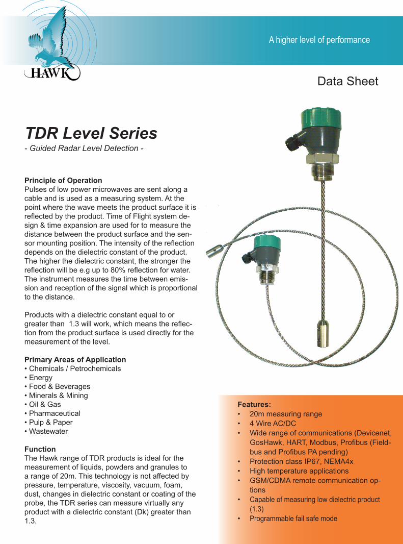
Data Sheet Principle of Operation Pulses of low power microwaves are sent along a cable and is used as a measuring system. At the point where the wave meets the product surface it is reflected by the product. Time of Flight system de- sign & time expansion are used for to measure the distance between the product surface and the sen- sor mounting position. The intensity of the reflection depends on the dielectric constant of the product. The higher the dielectric constant, the stronger the reflection will be e.g up to 80% reflection for water. The instrument measures the time between emis- sion and reception of the signal which is proportional to the distance. Products with a dielectric constant equal to or greater than 1.3 will work, which means the reflec- tion from the product surface is used directly for the measurement of the level. Primary Areas of Application • Chemicals / Petrochemicals • Energy • Food & Beverages • Minerals & Mining • Oil & Gas • Pharmaceutical • Pulp & Paper • Wastewater Function The Hawk range of TDR products is ideal for the measurement of liquids, powders and granules to a range of 20m. This technology is not affected by pressure, temperature, viscosity, vacuum, foam, dust, changes in dielectric constant or coating of the probe, the TDR series can measure virtually any product with a dielectric constant (Dk) greater than 1.3. A higher level of performance Features: 20m measuring range 4 Wire AC/DC Wide range of communications (Devicenet, GosHawk, HART, Modbus, Profibus (Field- bus and Profibus PA pending) Protection class IP67, NEMA4x High temperature applications GSM/CDMA remote communication op- tions Capable of measuring low dielectric product (1.3) Programmable fail safe mode • • • • • • • • TDR Level Series - Guided Radar Level Detection -
Transcript of TDR Level Series - Hawk Measure tdr.pdf · TDR - Guided Radar Series Measuring Principles...
Data Sheet
Principle of OperationPulses of low power microwaves are sent along a cable and is used as a measuring system. At the point where the wave meets the product surface it is reflected by the product. Time of Flight system de-sign & time expansion are used for to measure the distance between the product surface and the sen-sor mounting position. The intensity of the reflection depends on the dielectric constant of the product. The higher the dielectric constant, the stronger the reflection will be e.g up to 80% reflection for water. The instrument measures the time between emis-sion and reception of the signal which is proportional to the distance.
Products with a dielectric constant equal to or greater than 1.3 will work, which means the reflec-tion from the product surface is used directly for the measurement of the level.
Primary Areas of Application• Chemicals / Petrochemicals• Energy• Food & Beverages• Minerals & Mining• Oil & Gas• Pharmaceutical• Pulp & Paper• Wastewater
FunctionThe Hawk range of TDR products is ideal for the measurement of liquids, powders and granules to a range of 20m. This technology is not affected by pressure, temperature, viscosity, vacuum, foam, dust, changes in dielectric constant or coating of the probe, the TDR series can measure virtually any product with a dielectric constant (Dk) greater than 1.3.
A higher level of performance
Features:20m measuring range4 Wire AC/DCWide range of communications (Devicenet, GosHawk, HART, Modbus, Profibus (Field-bus and Profibus PA pending)Protection class IP67, NEMA4xHigh temperature applicationsGSM/CDMA remote communication op-tionsCapable of measuring low dielectric product (1.3)Programmable fail safe mode
•••
•••
•
•
TDR Level Series- Guided Radar Level Detection -
TDR - Guided Radar Series �
Measuring Principles
The Guided Radar (TDR) level meter has been de-veloped from a tried and tested technology histori-cally used to determine cable faults in transmission lines called Time Domain Reflectometry (TDR).
The device transmits low-intensity electromagnetic pulses of a few nanoseconds width along a rigid or flexible cable conductor. These pulses move at the speed of light. When the pulses reach the surface of the product to be measured, the pulses are reflected with a return signal size which is altered by the dielectric constant of the product (for exam-ple, water has a high dielectric constant and reflect the pulse back to the meter converter at 80% of its original intensity).
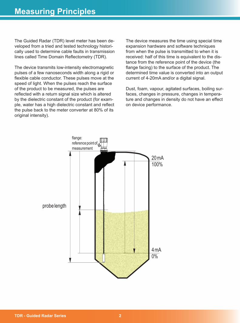
The device measures the time using special time expansion hardware and software techniques from when the pulse is transmitted to when it is received: half of this time is equivalent to the dis-tance from the reference point of the device (the flange facing) to the surface of the product. The determined time value is converted into an output current of 4-20mA and/or a digital signal.
Dust, foam, vapour, agitated surfaces, boiling sur-faces, changes in pressure, changes in tempera-ture and changes in density do not have an effect on device performance.
20 mA100%
4 mA0%
probe length
flange:reference pointofmeasurement
TDR - Guided Radar Series�
Measuring Principles
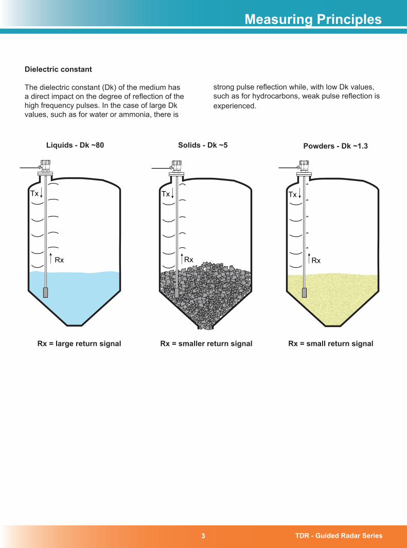
Dielectric constant
The dielectric constant (Dk) of the medium has a direct impact on the degree of reflection of the high frequency pulses. In the case of large Dk values, such as for water or ammonia, there is
strong pulse reflection while, with low Dk values, such as for hydrocarbons, weak pulse reflection is experienced.
Tx
Rx
Tx
Rx Rx
Tx
Liquids - Dk ~80 Solids - Dk ~5 Powders - Dk ~1.�
Rx = large return signal Rx = smaller return signal Rx = small return signal
TDR - Guided Radar Series �
Applications
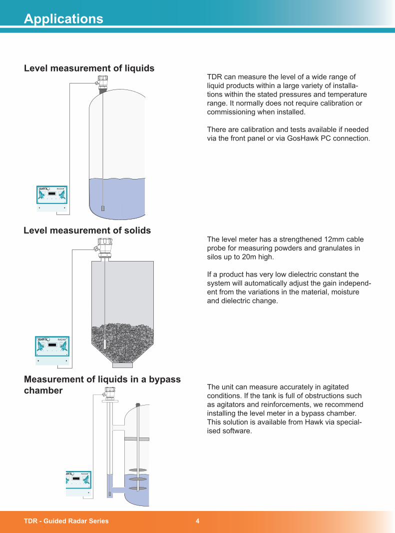
Level measurement of liquidsTDR can measure the level of a wide range of liquid products within a large variety of installa-tions within the stated pressures and temperature range. It normally does not require calibration or commissioning when installed.
There are calibration and tests available if needed via the front panel or via GosHawk PC connection.
Level measurement of solids
Measurement of liquids in a bypass chamber The unit can measure accurately in agitated
conditions. If the tank is full of obstructions such as agitators and reinforcements, we recommend installing the level meter in a bypass chamber. This solution is available from Hawk via special-ised software.
The level meter has a strengthened 12mm cable probe for measuring powders and granulates in silos up to 20m high.
If a product has very low dielectric constant the system will automatically adjust the gain independ-ent from the variations in the material, moisture and dielectric change.
RADAR
RADAR
RADAR
TDR - Guided Radar Series5
131.
5 m
m (5
.2”)
7.5
mm
(0.3
”)
192.5 mm (7.6”)
141.
5 m
m (5
.6”)
190
mm
(7.5
”)
182.5 mm (7.2”)
147 mm (5.8”)
167.
5 m
m (6
.6”)
147 mm (5.8”)
30.7
mm
(1.2
”)
158 mm (6.2”)
14 mm (0.6”)
74 mm (2.9”)
78 mm (3.1”)
107
mm
(4.2
”)
111.5 mm (4.4”)
4 mm (0.2”)
50 mm (2”)
108
mm
(4.3
”)
190
mm
(7.5
”)
174 mm (6.9”)192.5 mm (7.6”)
182.5 mm (7.2”)
Dimensions
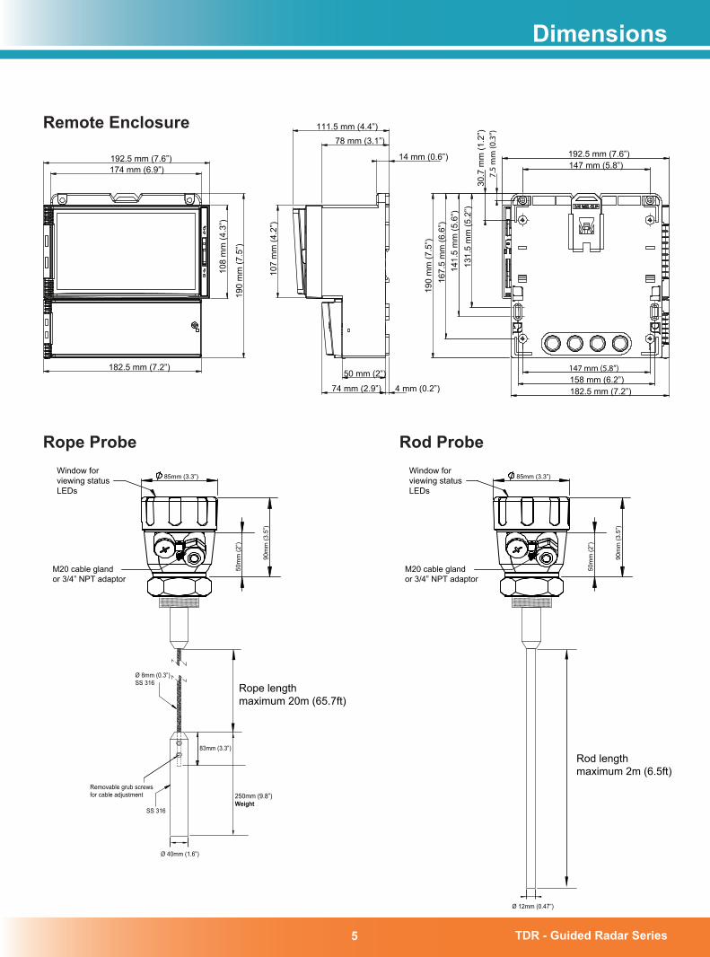
Remote Enclosure
85mm (3.3”)
M20 cable glandor 3/4” NPT adaptor
Window forviewing statusLEDs
90m
m (3
.5”)
50m
m (2
”)
SS 316
Removable grub screwsfor cable adjustment
Ø 8mm (0.3”)SS 316
250mm (9.8”)Weight
Ø 40mm (1.6”)
83mm (3.3”)
85mm (3.3”)
M20 cable glandor 3/4” NPT adaptor
Window forviewing statusLEDs
90m
m (3
.5”)
50m
m (2
”)
Ø 12mm (0.47”)
Rod lengthmaximum 2m (6.5ft)
Rope lengthmaximum 20m (65.7ft)
Rope Probe Rod Probe
TDR - Guided Radar Series �
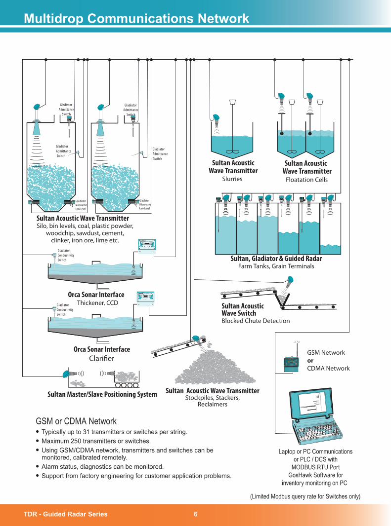
Multidrop Communications Network
Laptop or PC Communicationsor PLC / DCS with
MODBUS RTU PortGosHawk Software for
inventory monitoring on PC
GSM NetworkorCDMA Network
Floatation Cells
Sultan AcousticWave Transmitter
Slurries
GladiatorAdmittance Switch
Sultan Acoustic Wave TransmitterSilo, bin levels, coal, plastic powder,
woodchip, sawdust, cement,clinker, iron ore, lime etc.
Orca Sonar InterfaceThickener, CCD
GSM or CDMA Network• Typically up to 31 transmitters or switches per string.• Maximum 250 transmitters or switches.• Using GSM/CDMA network, transmitters and switches can be
monitored, calibrated remotely.• Alarm status, diagnostics can be monitored.• Support from factory engineering for customer application problems.
Sultan Acoustic Wave TransmitterStockpiles, Stackers,
Reclaimers
Sultan AcousticWave SwitchBlocked Chute Detection
Sultan, Gladiator & Guided RadarFarm Tanks, Grain Terminals
Orca Sonar Interface Clari�er
SULTAN 234
SULTAN 234
Gladiator Admittance
Switch
GladiatorAdmittance Switch
Gladiator Admittance
Switch
GLadiator MicrowaveLow Level
Gladiator MicrowaveLow Level
Sultan Master/Slave Positioning System
GladiatorConductivitySwitch
GladiatorConductivitySwitch
(Limited Modbus query rate for Switches only)
Sultan AcousticWave Transmitter
TDR - Guided Radar Series�
Terminal Connections for DC Supply – Model dependanta) 2 Wire DC Loop Powered
UserDC Supply
+–+
–
PLCDCSIND
4-20mA
Use shielded
cable
+
–4-20mA
RL 250 Ω
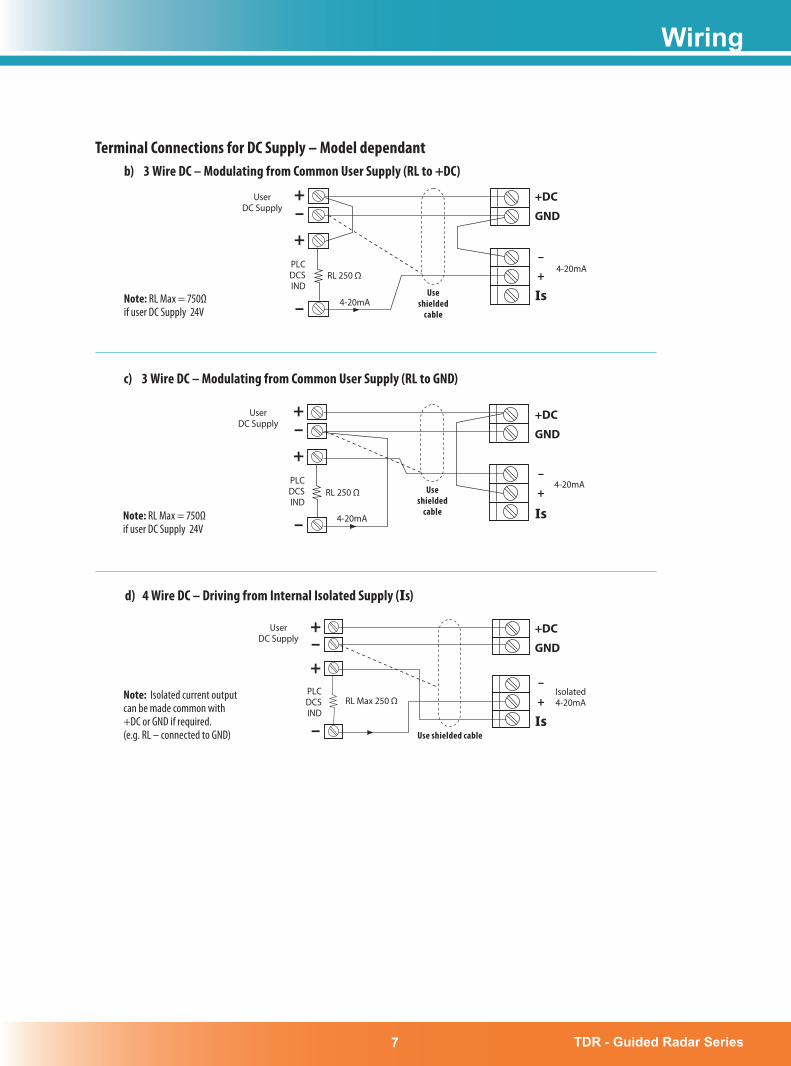
c) 3 Wire DC – Modulating from Common User Supply (RL to GND)
Note: RL Max = 750Ωif user DC Supply 24V
Use shielded
cable 4-20mA
RL 250 Ω
+–+
–
PLCDCSIND
+DC
GND
+
Is
–
UserDC Supply
Terminal Connections for DC Supply – Model dependantb) 3 Wire DC – Modulating from Common User Supply (RL to +DC)
+–+
– 4-20mA
+DC
GND
+
Is
–
Use shielded
cable
RL 250 Ω
UserDC Supply
PLCDCSIND
Note: RL Max = 750Ωif user DC Supply 24V
d) 4 Wire DC – Driving from Internal Isolated Supply (Is)
Note: Isolated current output can be made common with +DC or GND if required. (e.g. RL – connected to GND) Use shielded cable
+–+
–
UserDC Supply
PLCDCSIND
+DC
GND
+
Is
–
Is
4-20mA
Isolated4-20mA
4-20mA
RL Max 250 Ω
Note: RL Max = 600Ωif user DC Supply 24V
Wiring
TDR - Guided Radar Series 8
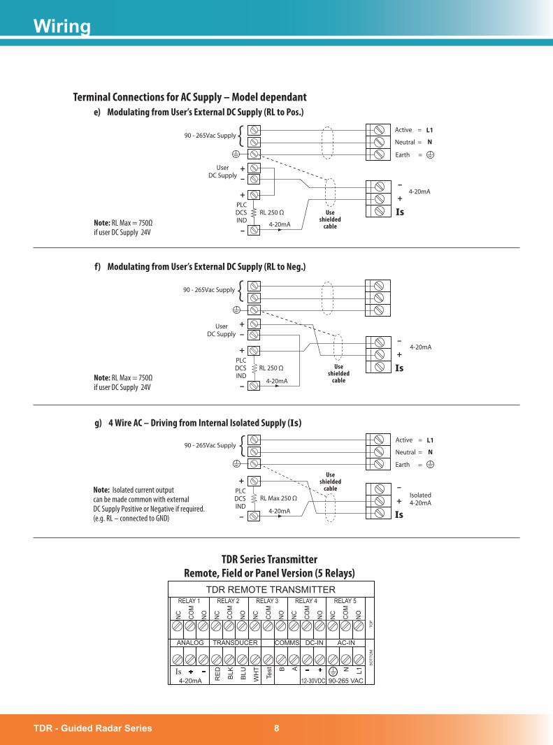
Terminal Connections for AC Supply – Model dependant
TDR Series TransmitterRemote, Field or Panel Version (5 Relays)
e) Modulating from User’s External DC Supply (RL to Pos.)
90 - 265Vac Supply
–
{–+
+
Neutral = N
Active = L1
UserDC Supply
PLCDCSIND 4-20mA
Useshielded
cable
RL 250 Ω
Note: RL Max = 750Ωif user DC Supply 24V
+
Is
–
f) Modulating from User’s External DC Supply (RL to Neg.)
4-20mA
{90 - 265Vac Supply
UserDC Supply
Note: RL Max = 750Ωif user DC Supply 24V –
–+
+PLCDCSIND
Useshielded
cable
RL 250 Ω
+
Is
–
g) 4 Wire AC – Driving from Internal Isolated Supply (Is)
+
Is
–
Neutral = N
Active = L1
Earth =Use
shieldedcable
4-20mA
RL Max 250 Ω
90 - 265Vac Supply {
–
+PLCDCSIND
Note: Isolated current output can be made common with external DC Supply Positive or Negative if required. (e.g. RL – connected to GND)
4-20mA
4-20mA
Isolated4-20mA
TDR REMOTE TRANSMITTER
BO
TTO
M
TOP
- - ++
RELAY 1 RELAY 2 RELAY 3 RELAY 4 RELAY 5
NC COM
NO NC COM
NO NC COM
NO NC COM
NO NC COM
NO
ANALOG TRANSDUCER COMMS DC-IN AC-IN
RE
D
BLK
BLU
WH
T
Te
st B A N L1
4-20mA 12-30VDC 90-265 VACIs
Earth =
Wiring
TDR - Guided Radar Series�
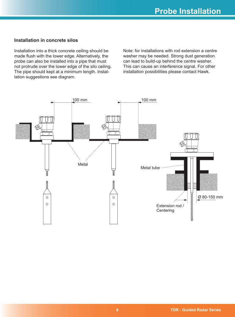
Installation in concrete silos
Installation into a thick concrete ceiling should be made flush with the lower edge. Alternatively, the probe can also be installed into a pipe that must not protrude over the lower edge of the silo ceiling. The pipe should kept at a minimum length. Instal-lation suggestions see diagram.
Probe Installation
Note: for installations with rod extension a centre washer may be needed. Strong dust generation can lead to build-up behind the centre washer. This can cause an interference signal. For other installation possibilities please contact Hawk.
100 mm 100 mm
Ø 80-150 mm
Metal
Extension rod /Centering
Metal tube
TDR - Guided Radar Series 10
Probe Installation
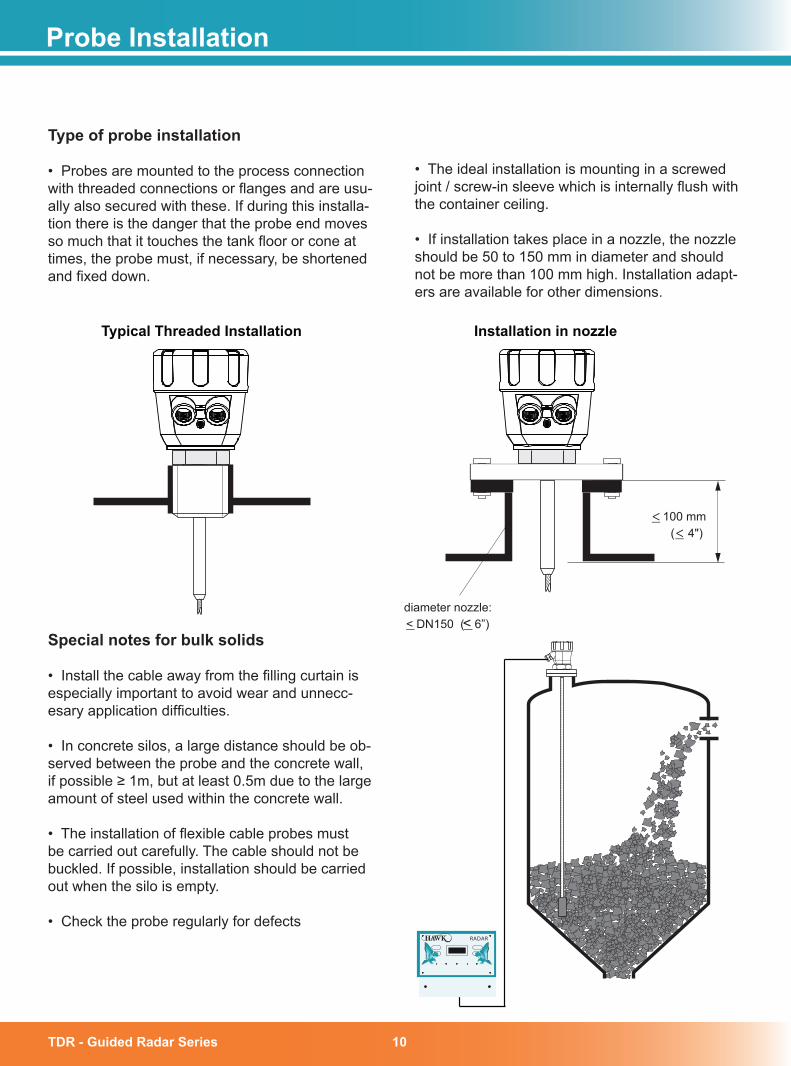
Type of probe installation
• Probes are mounted to the process connection with threaded connections or flanges and are usu-ally also secured with these. If during this installa-tion there is the danger that the probe end moves so much that it touches the tank floor or cone at times, the probe must, if necessary, be shortened and fixed down.
• The ideal installation is mounting in a screwed joint / screw-in sleeve which is internally flush with the container ceiling.
• If installation takes place in a nozzle, the nozzle should be 50 to 150 mm in diameter and should not be more than 100 mm high. Installation adapt-ers are available for other dimensions.
24 Endress+Hauser
diameter nozzle:< DN150 ( 6”)<
<<
100 mm( 4")
Typical Threaded Installation Installation in nozzle
Special notes for bulk solids
• Install the cable away from the filling curtain is especially important to avoid wear and unnecc-esary application difficulties.
• In concrete silos, a large distance should be ob-served between the probe and the concrete wall, if possible ≥ 1m, but at least 0.5m due to the large amount of steel used within the concrete wall.
• The installation of flexible cable probes must be carried out carefully. The cable should not be buckled. If possible, installation should be carried out when the silo is empty.
• Check the probe regularly for defectsRADAR
TDR - Guided Radar Series11
Probe Installation
TDR - Guided Radar Series
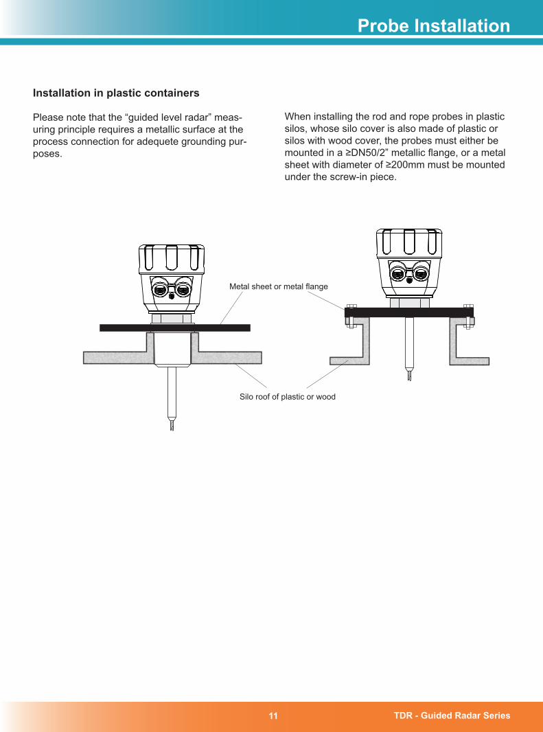
Installation in plastic containers
Please note that the “guided level radar” meas-uring principle requires a metallic surface at the process connection for adequete grounding pur-poses.
Metal sheet or metal flange
Silo roof of plastic or wood
When installing the rod and rope probes in plastic silos, whose silo cover is also made of plastic or silos with wood cover, the probes must either be mounted in a ≥DN50/2” metallic flange, or a metal sheet with diameter of ≥200mm must be mounted under the screw-in piece.
TDR - Guided Radar Series 1�
Operating Conditions
Probe selection
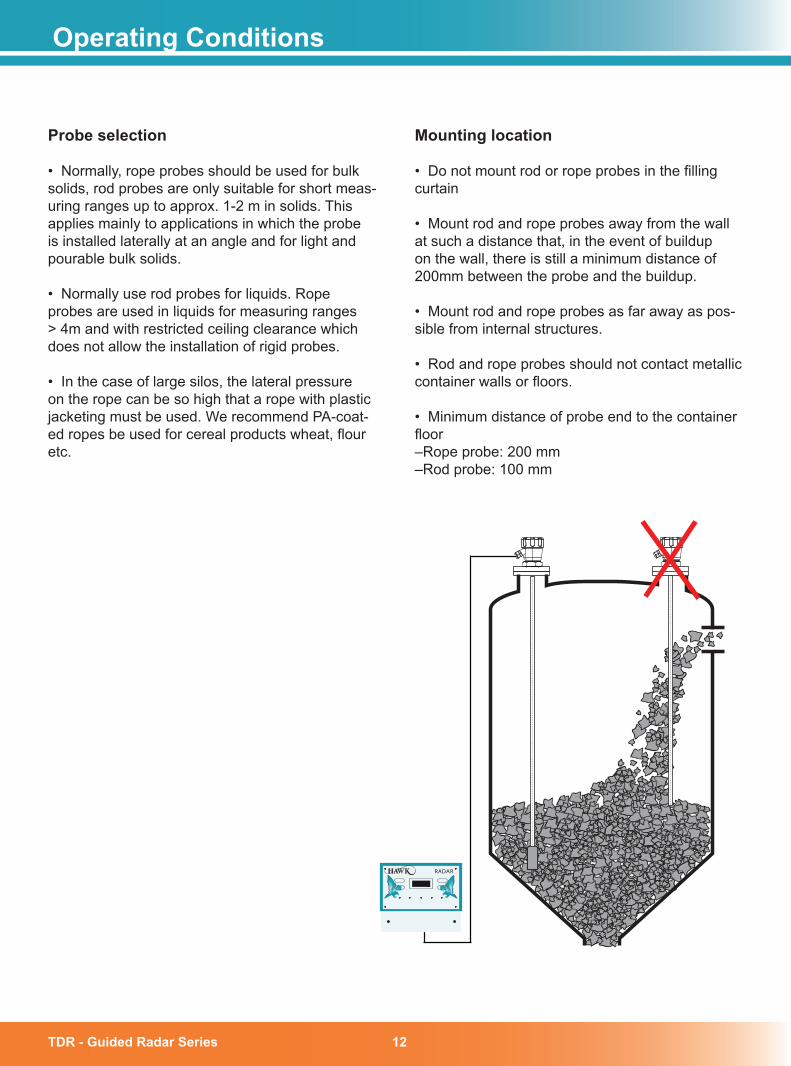
• Normally, rope probes should be used for bulk solids, rod probes are only suitable for short meas-uring ranges up to approx. 1-2 m in solids. This applies mainly to applications in which the probe is installed laterally at an angle and for light and pourable bulk solids.
• Normally use rod probes for liquids. Rope probes are used in liquids for measuring ranges > 4m and with restricted ceiling clearance which does not allow the installation of rigid probes.
• In the case of large silos, the lateral pressure on the rope can be so high that a rope with plastic jacketing must be used. We recommend PA-coat-ed ropes be used for cereal products wheat, flour etc.
Mounting location
• Do not mount rod or rope probes in the filling curtain
• Mount rod and rope probes away from the wall at such a distance that, in the event of buildup on the wall, there is still a minimum distance of 200mm between the probe and the buildup.
• Mount rod and rope probes as far away as pos-sible from internal structures.
• Rod and rope probes should not contact metallic container walls or floors.
• Minimum distance of probe end to the container floor –Rope probe: 200 mm–Rod probe: 100 mm
22 Endress+Hauser
RADAR
TDR - Guided Radar Series1�
Tensile Load
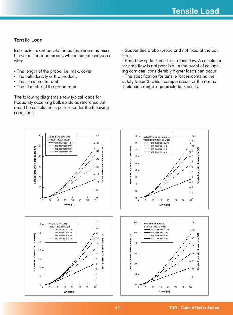
Tensile Load
Bulk solids exert tensile forces (maximum admissi-ble values on rope probes whose height increases with:
• The length of the probe, i.e. max. cover,• The bulk density of the product,• The silo diameter and• The diameter of the probe rope
The following diagrams show typical loads for frequently occurring bulk solids as reference val-ues. The calculation is performed for the following conditions:
0 5 10 15 20 25 30 350
10
20
30
40
50
60
Tens
ile fo
rce
with
6 m
m c
able
(kN
)
Level (m)
Silica sand tank withsmooth metallic walls
silo diameter 12 m silo diameter 9 m silo diameter 6 m silo diameter 3 m
0
5
10
15
20
25
30
35
40
Tens
ile fo
rce
with
4 m
m c
able
(kN
)
0 5 10 15 20 25 30 350
2
4
6
8
10
12
14
16
18
Tens
ile fo
rce
with
6 m
m c
able
(kN
)
Level (m)
polyethylene pellets tankwith smooth metallic walls
silo diameter 12 m silo diameter 9 m silo diameter 6 m silo diameter 3 m
0
1
2
3
4
5
6
7
8
9
10
11
12
Tens
ile fo
rce
with
4 m
m c
able
(kN)
0 5 10 15 20 25 30 350
5
10
15
20
25
30
35
Tens
ile fo
rce
with
6 m
m c
able
(kN
)
Level (m)
wheat tank withsmooth metallic walls
silo diameter 12 m silo diameter 9 m silo diameter 6 m silo diameter 3 m
0
2
4
6
8
10
12
14
16
18
20
22
24
Tens
ile fo
rce
with
4 m
m c
able
(kN
)
0 5 10 15 20 25 30 350
10
20
30
40
50
60
Tens
ile fo
rce
with
6 m
m c
able
(kN
)
Level (m)
cement tank withsmooth metallic walls
silo diameter 12 m silo diameter 9 m silo diameter 6 m silo diameter 3 m
0
5
10
15
20
25
30
35
40
Tens
ile fo
rce
with
4 m
m c
able
(kN
)
• Suspended probe (probe end not fixed at the bot-tom)• Free-flowing bulk solid, i.e. mass flow. A calculation for core flow is not possible. In the event of collaps-ing cornices, considerably higher loads can occur.• The specification for tensile forces contains the safety factor 2, which compensates for the normal fluctuation range in pourable bulk solids.
TDR - Guided Radar Series 1�
Since the tensile forces are also heavily dependent on the viscosity and highly abrasive characteristics of the product, a higher safety factor is necessary for these products and if there is a risk of corner buildup. In critical cases it is better to use a 12 mm rope instead of a smaller one.
The same forces also act on the silo cover so be aware of this and ensure the structure is capable of withstanding the dragging force generated. See table for typical values. On a rigid or flexible probe, the tensile forces are definitely greater, but this can not be calculated.
Observe the tensile strength of the probes or ensure that the tensile strength of the probes is not exceeded.
Options for reducing the tensile forces:• Shorten the probe.• If the maximum tensile load is exceeded, check whether it would be possible to use a non-contact Hawk Acoustic Wave devices which have many years of successful operation in all types of solids, powders and liquids.
Tensile Load
TDR - Guided Radar Series15
Typical Dielectric Constants
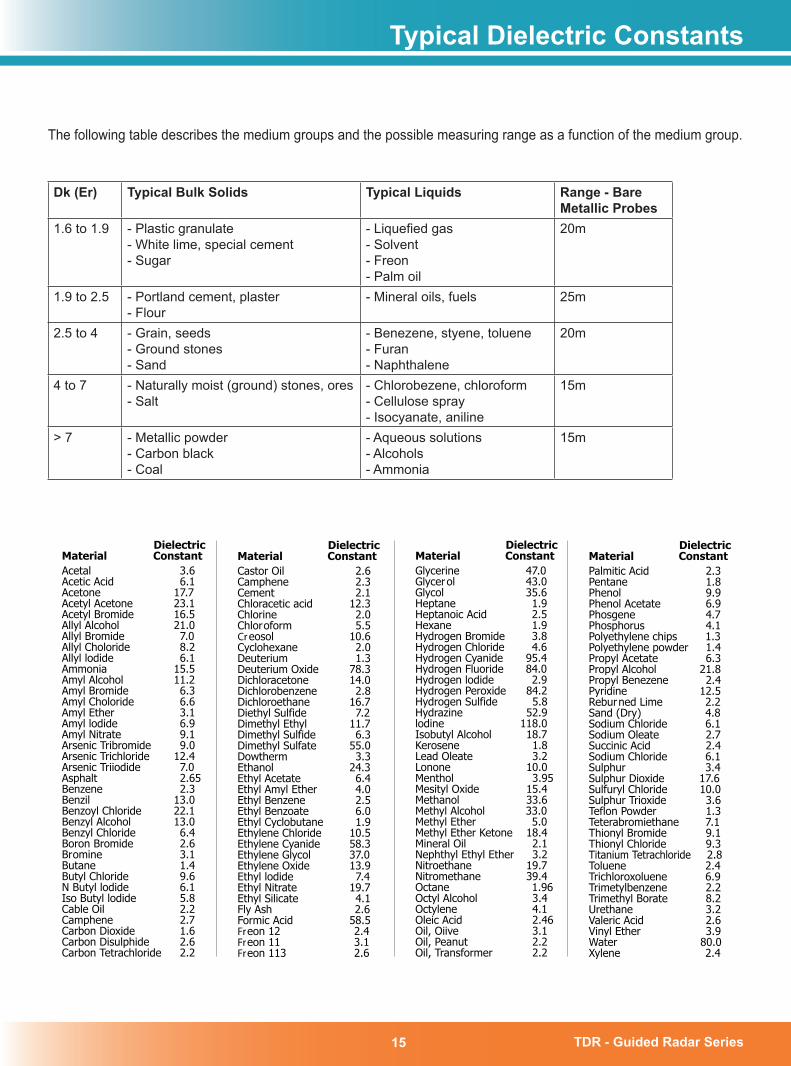
Dk (Er) Typical Bulk Solids Typical Liquids Range - Bare Metallic Probes
1.6 to 1.9 - Plastic granulate- White lime, special cement- Sugar
- Liquefied gas- Solvent- Freon- Palm oil
20m
1.9 to 2.5 - Portland cement, plaster- Flour
- Mineral oils, fuels 25m
2.5 to 4 - Grain, seeds- Ground stones- Sand
- Benezene, styene, toluene- Furan- Naphthalene
20m
4 to 7 - Naturally moist (ground) stones, ores- Salt
- Chlorobezene, chloroform- Cellulose spray- Isocyanate, aniline
15m
> 7 - Metallic powder- Carbon black- Coal
- Aqueous solutions- Alcohols- Ammonia
15m
The following table describes the medium groups and the possible measuring range as a function of the medium group.
DielectricMaterial ConstantGlycerine 47.0Glycerol 43.0Glycol 35.6Heptane 1.9Heptanoic Acid 2.5Hexane 1.9Hydrogen Bromide 3.8Hydrogen Chloride 4.6Hydrogen Cyanide 95.4Hydrogen Fluoride 84.0Hydrogen lodide 2.9Hydrogen Peroxide 84.2Hydrogen Sulfide 5.8Hydrazine 52.9lodine 118.0Isobutyl Alcohol 18.7Kerosene 1.8Lead Oleate 3.2Lonone 10.0Menthol 3.95Mesityl Oxide 15.4Methanol 33.6Methyl Alcohol 33.0Methyl Ether 5.0Methyl Ether Ketone 18.4Mineral Oil 2.1Nephthyl Ethyl Ether 3.2Nitroethane 19.7Nitromethane 39.4Octane 1.96Octyl Alcohol 3.4Octylene 4.1Oleic Acid 2.46Oil, Oiive 3.1Oil, Peanut 2.2Oil, Transformer 2.2
For other materials contact the factory
DielectricMaterial ConstantAcetal 3.6Acetic Acid 6.1Acetone 17.7Acetyl Acetone 23.1Acetyl Bromide 16.5Allyl Alcohol 21.0Allyl Bromide 7.0Allyl Choloride 8.2Allyl lodide 6.1Ammonia 15.5Amyl Alcohol 11.2Amyl Bromide 6.3Amyl Choloride 6.6Amyl Ether 3.1Amyl lodide 6.9Amyl Nitrate 9.1Arsenic Tribromide 9.0Arsenic Trichloride 12.4Arsenic Triiodide 7.0Asphalt 2.65Benzene 2.3Benzil 13.0Benzoyl Chloride 22.1Benzyl Alcohol 13.0Benzyl Chloride 6.4Boron Bromide 2.6Bromine 3.1Butane 1.4Butyl Chloride 9.6N Butyl lodide 6.1Iso Butyl lodide 5.8Cable Oil 2.2Camphene 2.7Carbon Dioxide 1.6Carbon Disulphide 2.6Carbon Tetrachloride 2.2
DielectricMaterial ConstantCastor Oil 2.6Camphene 2.3Cement 2.1Chloracetic acid 12.3Chlorine 2.0Chloroform 5.5Creosol 10.6Cyclohexane 2.0Deuterium 1.3Deuterium Oxide 78.3Dichloracetone 14.0Dichlorobenzene 2.8Dichloroethane 16.7Diethyl Sulfide 7.2Dimethyl Ethyl 11.7Dimethyl Sulfide 6.3Dimethyl Sulfate 55.0Dowtherm 3.3Ethanol 24.3Ethyl Acetate 6.4Ethyl Amyl Ether 4.0Ethyl Benzene 2.5Ethyl Benzoate 6.0Ethyl Cyclobutane 1.9Ethylene Chloride 10.5Ethylene Cyanide 58.3Ethylene Glycol 37.0Ethylene Oxide 13.9Ethyl lodide 7.4Ethyl Nitrate 19.7Ethyl Silicate 4.1Fly Ash 2.6Formic Acid 58.5Freon 12 2.4Freon 11 3.1Freon 113 2.6
DielectricMaterial ConstantPalmitic Acid 2.3Pentane 1.8Phenol 9.9Phenol Acetate 6.9Phosgene 4.7Phosphorus 4.1Polyethylene chips 1.3Polyethylene powder 1.4Propyl Acetate 6.3Propyl Alcohol 21.8Propyl Benezene 2.4Pyridine 12.5Reburned Lime 2.2Sand (Dry) 4.8Sodium Chloride 6.1Sodium Oleate 2.7Succinic Acid 2.4Sodium Chloride 6.1Sulphur 3.4Sulphur Dioxide 17.6Sulfuryl Chloride 10.0Sulphur Trioxide 3.6Teflon Powder 1.3Teterabromiethane 7.1Thionyl Bromide 9.1Thionyl Chloride 9.3Titanium Tetrachloride 2.8Toluene 2.4Trichloroxoluene 6.9Trimetylbenzene 2.2Trimethyl Borate 8.2Urethane 3.2Valeric Acid 2.6Vinyl Ether 3.9Water 80.0Xylene 2.4
TDR - Guided Radar Series 1�
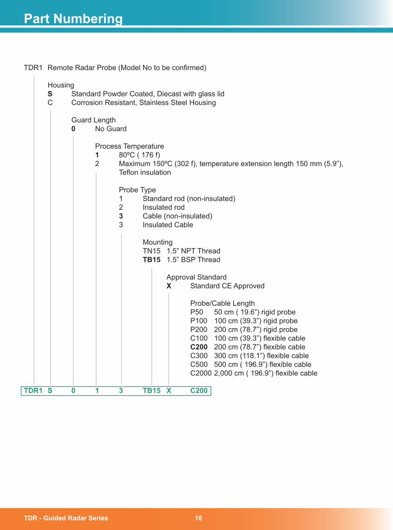
TDR1 Remote Radar Probe (Model No to be confirmed) Housing S Standard Powder Coated, Diecast with glass lid C Corrosion Resistant, Stainless Steel Housing
Guard Length 0 No Guard
Process Temperature 1 80ºC ( 176 f) 2 Maximum 150ºC (302 f), temperature extension length 150 mm (5.9”), Teflon insulation
Probe Type 1 Standard rod (non-insulated) 2 Insulated rod � Cable (non-insulated) 3 Insulated Cable
Mounting TN15 1.5” NPT Thread TB15 1.5” BSP Thread
Approval Standard X Standard CE Approved
Probe/Cable Length P50 50 cm ( 19.6”) rigid probe P100 100 cm (39.3”) rigid probe P200 200 cm (78.7”) rigid probe C100 100 cm (39.3”) flexible cable C�00 200 cm (78.7”) flexible cable C300 300 cm (118.1”) flexible cable C500 500 cm ( 196.9”) flexible cable C2000 2,000 cm ( 196.9”) flexible cable TDR1 S 0 1 � TB15 X C�00
Part Numbering
TDR - Guided Radar Series1�
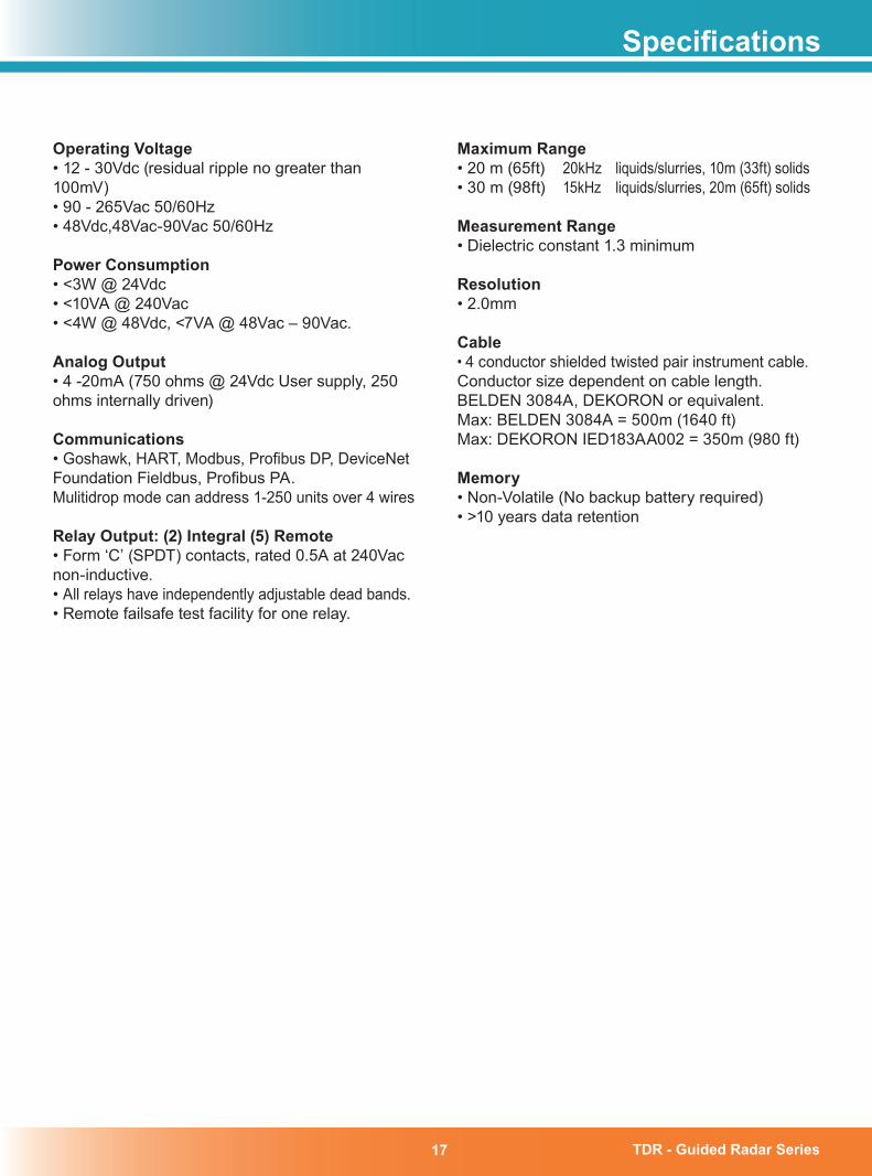
Operating Voltage• 12 - 30Vdc (residual ripple no greater than 100mV)• 90 - 265Vac 50/60Hz• 48Vdc,48Vac-90Vac 50/60Hz
Power Consumption• <3W @ 24Vdc• <10VA @ 240Vac• <4W @ 48Vdc, <7VA @ 48Vac – 90Vac.
Analog Output• 4 -20mA (750 ohms @ 24Vdc User supply, 250 ohms internally driven)
Communications• Goshawk, HART, Modbus, Profibus DP, DeviceNetFoundation Fieldbus, Profibus PA.Mulitidrop mode can address 1-250 units over 4 wires
Relay Output: (�) Integral (5) Remote• Form ‘C’ (SPDT) contacts, rated 0.5A at 240Vac non-inductive. • All relays have independently adjustable dead bands.• Remote failsafe test facility for one relay.
Specifications
Maximum Range• 20 m (65ft) 20kHz liquids/slurries, 10m (33ft) solids• 30 m (98ft) 15kHz liquids/slurries, 20m (65ft) solids
Measurement Range• Dielectric constant 1.3 minimum
Resolution• 2.0mm
Cable• 4 conductor shielded twisted pair instrument cable.Conductor size dependent on cable length. BELDEN 3084A, DEKORON or equivalent.Max: BELDEN 3084A = 500m (1640 ft)Max: DEKORON IED183AA002 = 350m (980 ft)
Memory• Non-Volatile (No backup battery required)• >10 years data retention
TDR - Guided Radar Series 18
Contact Information
Hawk Measurement Systems (Head Office)15-17 Maurice CourtNunawading VIC 3131AustraliaPhone: +61 3 9873 4750Fax: +61 3 9873 [email protected]
Contact
Hawk Measurement 7 River StreetMiddleton, MA 01949USAPhone: +1 888 HAWKLEVEL (1-888-429-5538)Phone: +1 978 304 3000Fax: +1 978 304 [email protected]
For more information and global representatives: www.hawkmeasure.com
Represented by:
Rev 1.2, May 2009
Additional product warranty and application guarantees upon request. Technical data subject to change without notice. All
com
pany
or p
rodu
ct n
ames
are
regi
ster
ed tr
adem
arks
or t
rade
mar
ks o
f the
ir re
spec
tive
owne
rs.


![c Consult author(s) regarding copyright matters · dielectric material with dielectric constant around ~3.1 at 1 KHz [22]. Due to its low dielectric constant (low-K), PC dielectric](https://static.fdocuments.net/doc/165x107/5e8ef91e49d7e74eaa111a6e/c-consult-authors-regarding-copyright-matters-dielectric-material-with-dielectric.jpg)