
TDM Transport over mpls v 1.1
120
VPWS CPIPE / CES TDM Transport over NOKIA Metro-e A. Achyar Nur – Advanced Technical Department 1
-
Upload
a-achyar-nur -
Category
Internet
-
view
173 -
download
7
Transcript of TDM Transport over mpls v 1.1

VPWSCPIPE / CES
TDM Transport over NOKIA Metro-eA. Achyar Nur – Advanced Technical Department
1

Agenda (1)• PCM (Pulse Code Modulation) Communication System
• E1 vs T1
• SDH and Why SDH?• SDH Layer Model
• Path Section
• SONET
2/20/2016 2

Agenda (2)• Clocking/Network Synchronization
• Terminology
• SDH Clock
• Clocking Status
• Time Provisioning
• Packet Based Clock Synchronization
2/20/2016 3

Agenda (3)• TDM in NOKIA
• Hardware Requirement
• Port Configuration
• TDM over MPLS NOKIA Service
• NOKIA Synchronization System
2/20/2016 4

Agenda (4)• Troubleshooting
• Kind of Alarm
• BER Test Configuration
• Use Case
• FAQ
2/20/2016 5

VPWSCPIPE / CES
PCM (Pulse Code Modulation) Communication System
2/20/2016 6

E1 vs T1 (1)
• E1 and T1 is kind of Plesiochronous Data Hierarchy (PDH)
2/20/2016 7

E1 vs T1 (2)
2/20/2016 8

E1 vs T1 (3)
2/20/2016 9

E1 vs T1 (4)P
DH
Hie
rarc
hy
2/20/2016 10

E1 vs T1 (5)P
DH
Hie
rarc
hy
2/20/2016 11

Synchronous Data Hierarchy (SDH) (1)
• SDH is PCM communication system that using synchronous clock to deliver traffic
• SDH (Synchronous Data Hierarchy) and Why SDH?• High transmission rates
• Disadvantages inherent in PDH
• Simplified drop and insert function
• High availability and capacity matching
• Reliability
• Future-proof platform for new services
• Interconnection
2/20/2016 12

Synchronous Data Hierarchy (SDH) (2)
• Network Components
2/20/2016 13

Synchronous Data Hierarchy (SDH) (3)
• SDH Layer Model
2/20/2016 14

Synchronous Data Hierarchy (SDH) (4)
• Mapping and Muxing in SDH
2/20/2016 15

Synchronous Data Hierarchy (SDH) (5)
• Mapping and Muxing in SDH (2)
2/20/2016 16

Synchronous Data Hierarchy (SDH) (6)
• SDH – SONET Equivalention
2/20/2016 17

Synchronous Data Hierarchy (SDH) (7)
• Automatic Protection Switching (APS)
Linear Protection Uni-directional Ring Bi-directional Ring
2/20/2016 18

Synchronous Data Hierarchy (SDH) (8)
• Network Synchronization
2/20/2016 19

Synchronous Optical Networking (SONET) (1)
• Network Components
2/20/2016 20

Synchronous Optical Networking (SONET) (2)
• SONET Layer
2/20/2016 21

Synchronous Optical Networking (SONET) (3)
• Mapping and Muxing in SONET
2/20/2016 22

Synchronous Optical Networking (SONET) (4)
• Automatic Protection Switching (APS) (1)
1+1 Protection Scheme 1:1 Protection Scheme 1:N Protection Scheme
2/20/2016 23

Synchronous Optical Networking (SONET) (5)
• Automatic Protection Switching (APS) (2)
Uni-directional Ring Bi-directional Ring
2/20/2016 24

Synchronous Data Hierarchy (SDH) (6)
• Network Synchronization
2/20/2016 25

VPWSCPIPE / CES
Network Synchronization
2/20/2016 26

Clocking Terminology
• Synchronization is required in order to meet network performance and availability requirements.
• Poor network synchronization will lead to large amounts of Jitter and Wander.
• This Jitter and Wander can lead to transmission errors and buffer under/overflow.
2/20/2016 27

SDH Clock
• SDH Network Synchronization Clock Architecture
2/20/2016 28

SDH Clock (2)
• Element of Synchronization (ETSI EG 201 793)
2/20/2016 29

SDH Clock (3)
• Methods to Synchronize Telecommunication Networks
Centralized master clock network synchronization
Fully distributed master clocks network synchronization
Partially distributed master clocks network synchronization
2/20/2016 30

Clocking Status
• Clock Operation Mode• free running mode
• holdover mode
• ideal operation
• locked mode
• stressed operation
2/20/2016 31

Time Provisioning
• Time Provisioning
External Timing Line Timing Looped Timing Through Timing
Internal Timing
2/20/2016 32

Packet Based Clock Synchronization
• Ethernet is inherently an asynchronous networking system.
• Differences in timing at nodes within a network cause the receiving node to either drop or reread information sent to it.
• Achieve the required synchronization of the TDM nodes across the asynchronous Ethernet network, a clock recovery mechanism must be employed at the receiver side of a CESoETH connection.
2/20/2016 33

Packet Based Clock Synchronization (2)
• There are three categories of Clock solutions:• External source – GPS or TDM network. This is outside the scope of the Carrier Ethernet
domain.
• Synchronization of packet network – elaborated in the following sections.
• Synchronization over physical Ethernet – Synchronous Ethernet or SyncE
2/20/2016 34

Packet Based Clock Synchronization (3)
• Technique for Sync:
1. Adaptive Clock Recovery (ACR)2. Network Time Protocol (NTP)3. IEEE-1588 v2 (PTP)4. Synchronous Ethernet (Sync-E)
2/20/2016 35

Packet Based Clock Synchronization (4)
• Adaptive Clock Recovery (ACR)• Adaptive Clock Recovery (ACR) is
used in conjunction with circuit emulation services.
• adaptive methods adjust a local frequency reference to ensure that the rate of data being transmitted by the packet to TDM IWF matches the rate of data reception at the TDM to packet IWF.
2/20/2016 36

Packet Based Clock Synchronization (5)
• Adaptive Clock Recovery (ACR)(2)
2/20/2016 37

Packet Based Clock Synchronization (6)
• Network Time Protocol (NTP)• The main issue with NTP is that its accuracy can degrade substantially during periods of
network congestion
• defined in RFC 1305, including a recovery algorithm
• protocol uses four timestamps
• It was not designed for highly accurate frequency distribution, as is now being considered for telecommunication applications, nor for the highly accurate phase requirements of the TDD mobile technologies.
2/20/2016 38

Packet Based Clock Synchronization (7)
• Network Time Protocol (NTP) (2)
2/20/2016 39

Packet Based Clock Synchronization (8)
• The Precision Time Protocol (PTP)• IEEE1588v2 and its Precision Time Protocol (PTP) message exchange is another
mechanism that can be used to synchronize time and timing within a network
• Providing the highest level of accurate frequency, phase, and time of day to wireless backhaul networks.
• Similar with NTP but enhance some hardware-based time-stamping
2/20/2016 40

Packet Based Clock Synchronization (9)
• The Precision Time Protocol (PTP)(2)• PTP Component
2/20/2016 41
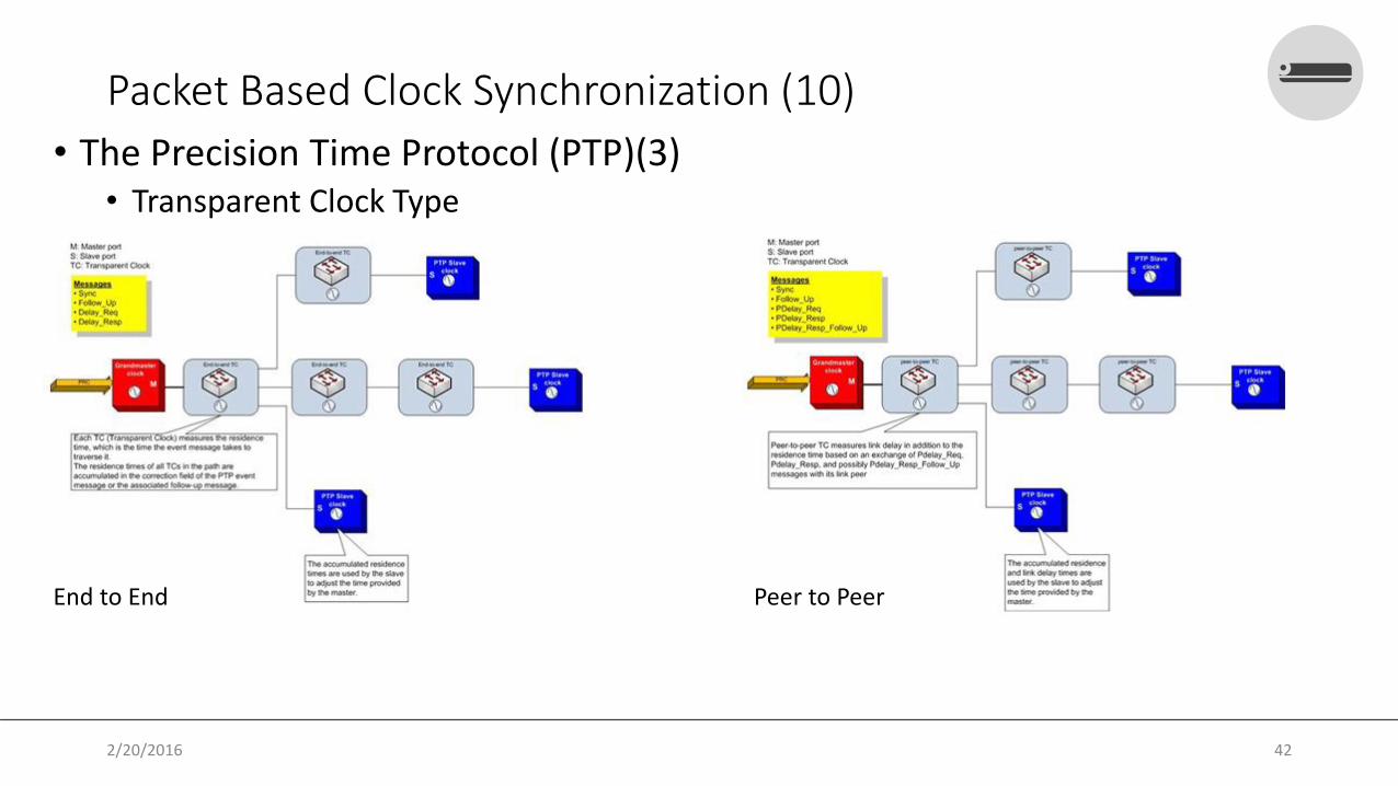
Packet Based Clock Synchronization (10)
• The Precision Time Protocol (PTP)(3)• Transparent Clock Type
End to End Peer to Peer
2/20/2016 42

Packet Based Clock Synchronization (11)
• Synchronous Ethernet• The Synchronous Ethernet (SyncE) approach provides a mechanism to deliver a
network traceable physical layer clock over IEEE 802.3 PHYs with Ethernet Equipment Clock (EEC) as specified in ITU-T G.8262.
• The architectural aspects of Synchronous Ethernet are defined in ITU-T G.8261. SyncEprovides the capability to provide an Ethernet clock that is traceable to a primary reference clock (PRC) as defined in ITU-T G.811
• It should be noted that SyncE requires all network elements in the network to be upgraded to support SyncE. Therefore SyncE might only be practical for use in small network domains, while a hybrid solution complemented by a packet-based synchronization method would be required to extend its reach.
2/20/2016 43

Packet Based Clock Synchronization (12)
• Synchronous Ethernet (2)• Synchronous Status Message (SSM)
• Determine the quality level of the clock sourcing a given synchronization trail
• Allow a network element to select the best of multiple input synchronization trails
• Avoid the creation of timing loops.
• SSM of Synchronous Ethernet uses an Ethernet OAM PDU that uses the slow protocol subtype (ITU-T G.8264)
• SSM of Synchronous Ethernet uses an Ethernet OAM PDU that uses the slow protocol subtype.
2/20/2016 44

Packet Based Clock Synchronization (13)
• Synchronous Ethernet (3)• Synchronous Ethernet (Sync-E)
• Ethernet Port can derive the physical layer transmitter clock
• Not influenced by impairments introduced by the higher levels of the networking technology (packet loss, packet delay variation).
2/20/2016 45

Packet Based Clock Synchronization (14)
• Synchronous Ethernet (4)
2/20/2016 46

Packet Based Clock Synchronization (15)
• Synchronous Ethernet (5)
2/20/2016 47

VPWSCPIPE / CES
TDM in NOKIA
2/20/2016 48

Hardware Requirement• 7x50 Product Family Hardware Support for TDM
• OC-3• OC-3 ASAP• OC-12/3• OC-48• OC-192• OC-768• OC-12 ASAP• Channelized OC3• Channelized OC12• ATM OC-12/3• ATM OC-12• Channelized ASAP OC3• Channelized ASAP OC12
2/20/2016 49

Hardware Requirement (2)
• 7x50 Product Family Hardware Support for TDM (2)• Mapping port Hierarchy
2/20/2016 50

Hardware Requirement (3)• 7x50 Product Family Hardware Support for TDM (3)
• Mapping Port for OC12
2/20/2016 51

Hardware Requirement (4)• 7x50 Product Family Hardware Support for TDM (4)
• Mapping Port for DS3
2/20/2016 52

Hardware Requirement (5)• 7705 Product Family Hardware Support for TDM
• 16-port T1/E1 ASAP Adapter card • 32-port T1/E1 ASAP Adapter card• 12-port Serial Data Interface card• 6-port E&M Adapter card• 2-port OC3/STM1 Channelized Adapter card• 4-port OC3/STM1 Channelized Adapter card• 4-port DS3/E3 Adapter card • 8-port Voice & Teleprotection card• 4-port T1/E1 and RS-232 Combination module • 8-port FXO Adapter card • 6-port FXS Adapter card
2/20/2016 53

Hardware Requirement (6)• 7705 Product Family Hardware Support for TDM (2)
68-pin AMP to 68-pin AMP Cable 68-pin AMP to Ended-Wire
2/20/2016 54

Hardware Requirement (6)• Digital Distribution Frame (DDF)
DDF LSA Type
DDF K52 Type
2/20/2016 55

Mapping Port to LSA • SAR-8 Use-case
2/20/2016 56

Mapping Port to LSA (2)• SAR-8 Use-case
• Rule:• One LSA Block serve 5 E1 Channel/Port
• Each Port has TX and RX
• Each Sub-bundle cable contains 4 cable.• Each Sub-bundle cable contains 2 port
• Each TX and RX using 2 cable from E1/T1 cable, for mapping you may see the table above
• TX and RX must be cross pair, it means, If the RX cable using white-blue, so the TX cable using Turquoise-Violet (Please see the table to help you understand)
• On The LSA, mapping the RX cable first ( MAP-1) then continue with the TX cable (MAP-2)
2/21/2016 57

Mapping Port to LSA (3)• SAR-8 Use-case
• Mapping Cable for Each Port in One Block LSA Based on Table mapping and Rule
2/21/2016 58

Port Configuration• Port Configuration as Network Port
OC-X Port = STM-1 Payload
port x/y/xdescription “STM-1 Carrier Network"sonet-sdh
framing sdhpath
mode networkencap-type ppp-autono shutdown
exitexitno shutdown
exit
Mapping to Interface
interface “STM-1 Carrier"address 192.168.19.193/30description “STM-1 Carrier"port x/y/zdhcp
shutdownexit
exit
2/20/2016 59

Port Configuration(2)• Port Configuration as Network Port(2)
E-1/T-1/DS-1 Port
port x/y/xdescription “E1 Carrier Trans"tdm
e1 channel-group 1
mode networkencap-type ppp-autono shutdown
exitno shutdown
exitexitno shutdown
exit
N x E-1 Carrier for Transmission
port bundle-ppp-x/y.adescription “N * E-1 Carrier"multilink-bundle
member x/y/1.amember x/y/2.amember x/y/3.amember x/y/4.amrru 2048
exitno shutdown
exit
2/20/2016 60

Port Configuration(3)• Port Configuration as Network Port(3)
Mapping to Interface
interface “N* E-1 Carrier Transmission"shutdownaddress 192.168.0.5/30port bundle-ppp-x/y.adhcp
shutdownexit
exit
2/20/2016 61

Port Configuration(4)• Port Configuration as Access Port
OC-X Port Configuration
port x/y/xdescription “OC-X Access Port"sonet-sdh
framing sdhclock-source node-timed
exitno shutdown
exit
APS Configuration Using uni-directional Sw-Mode
Note: see clock source reference, in NOKIA: there 3 clock source reference:- node-timed- Looped- timed- adaptive
2/20/2016 62

Port Configuration(5)• Port Configuration as Access Port (2)
Mapping To Service
cpipe abcdefgh customer opq vc-type satop-e1 createdescription “Access Service E1"service-name “Acess Service E-1"sap aps-2.3.2.1.2.1 createexitspoke-sdp opqrs:abcdefgh create
no shutdownexitno shutdown
exit
2/20/2016 63

Port Configuration(6)• Port Configuration as Access Port (3)
DS-3 Port Configuration Un-Channelized
port x/y/zdescription “Un-Channelized Access"tdm
ds3 encap-type cemclock-source loop-timedframing ds3-unframedno shutdown
exitexitno shutdown
exit
APS Configuration Using uni-directional Sw-Mode
Note: see clock source reference, in NOKIA: there 3 clock source reference:- node-timed- Looped- timed- adaptive
2/20/2016 64

Port Configuration(7)• Port Configuration as Access Port (4)
Mapping To Service DS3-Un-Channelized
cpipe abcdfgh customer opq vc-type satop-t3 createdescription “DS3 Un-channelized"sap x/y/z createexitspoke-sdp opqrs:abcdfgh createexitno shutdown
exit
2/20/2016 65

Port Configuration(8)• Port Configuration as Access Port (5)
Mapping To Service DS3-Channelized
cpipe abcdfgh customer opq vc-type satop-t3 createdescription “DS3 Un-channelized"sap x/y/z.a createexitspoke-sdp opqrs:abcdfgh createexitno shutdown
exit
2/20/2016 66

Port Configuration(9)• Port Configuration as Access Port (6)
E-1 Port Configuration non Bundling
port x/y/zdescription “E-1 Non Bundling"tdm
e1 framing e1-unframedchannel-group 1
encap-type cemno shutdown
exitno shutdown
exitexitno shutdown
exit
Mapping Port to Service
cpipe abcd customer hij vc-type satop-e1 createdescription “E1- non bundling Service"sap x/y/z.a createexitspoke-sdp ab:wxyz createexitno shutdown
exit
2/20/2016 67

Port Configuration(10)• Port Configuration as Access Port (7)
E-1 Port Configuration Bundling
port x/y/zdescription “E-1 Access Bundling"tdm
e1 channel-group 1
encap-type atmno shutdown
exitno shutdown
exitexitno shutdown
exit
N x E-1 Carrier for Access
port bundle-ima-x/y.adescription “Bundling Access"multilink-bundle
imaatmexit
exitmember x/y/1.amember x/y/2.amember x/y/3.amember z/y/4.a
exitno shutdown
exit
2/20/2016 68

Port Configuration(11)• Port Configuration as Access Port (8)
Mapping To N*E-1 Service Channel
apipe abcdef customer jklmn vc-type atm-vpc createdescription “ATM IP Using TDM"sap bundle-ima-x/y.a:b createexitspoke-sdp rst:abcdef createexitno shutdown
exit
2/20/2016 69

TDM over MPLS NOKIA Service
• NOKIA TDM Service Terminology
• TDM PW based on IETF PWE3 called Cpipe
• Circuit Mode:• Unstructured Mode (SAToP)
• Structured Mode (CESoPSN)
• MEF8 Allow both of them (CESoETH)
2/20/2016 70

TDM over MPLS NOKIA Service (2)
• Unstructured Frames (SAToP)• Structure-agnostic TDM over Packet
• used for the transport of unstructured TDM or structured TDM (where the structure is ignored).
• SAToP service does not align to any framing
2/20/2016 71

TDM over MPLS NOKIA Service (3)
• Structured Frames (CESoPSN)• Selecting only the necessary n × 64 kb/s timeslots to transport
• Framing bits (DS1) or FAS (E1) are terminated at the near end and reproduced at the far end
• To mapping payload using CAS (Channel Associate Sygnaling)
2/20/2016 72

TDM over MPLS NOKIA Service (4)
• Structured Frames (CESoPSN) (2)• Structured Frames for E-1 Multiframe
2/20/2016 73
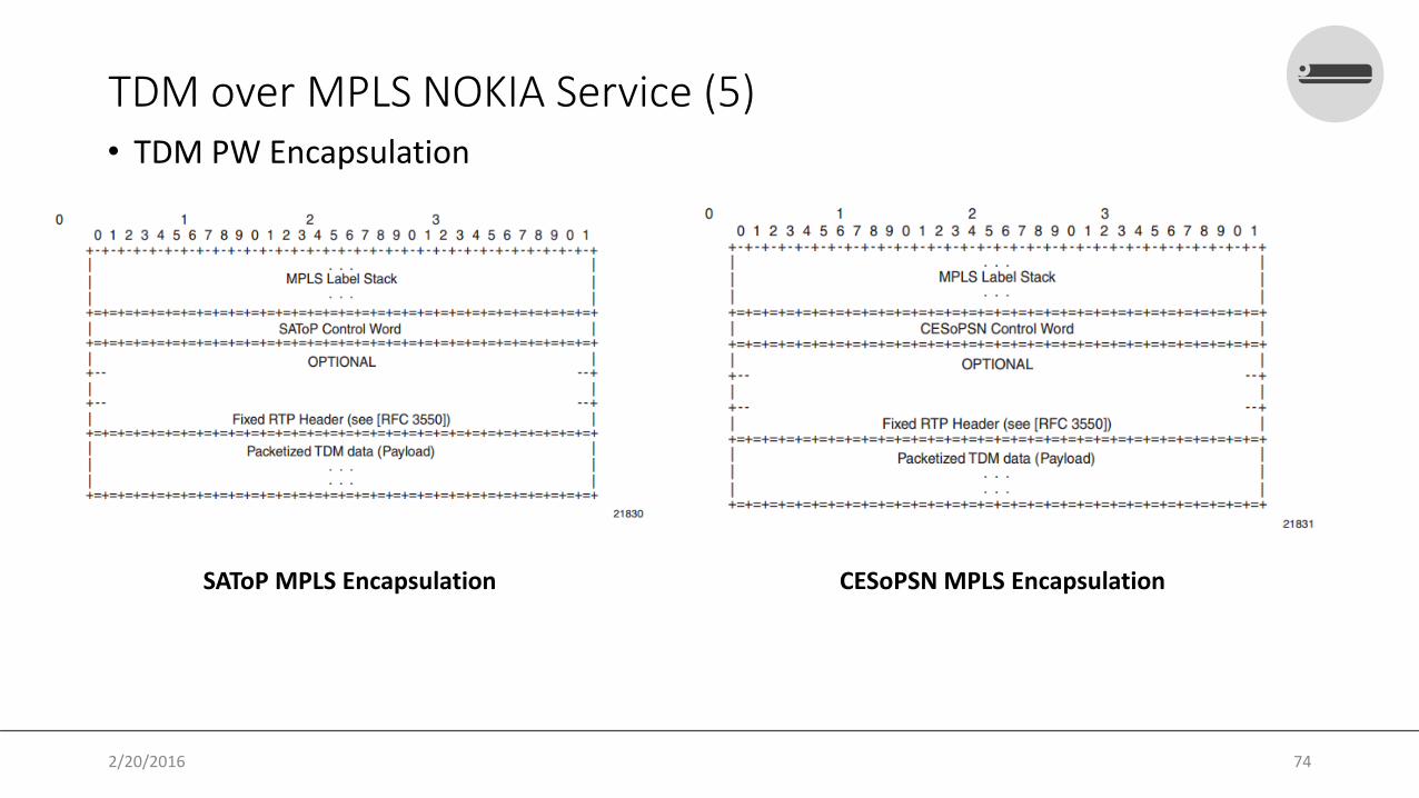
TDM over MPLS NOKIA Service (5)• TDM PW Encapsulation
SAToP MPLS Encapsulation CESoPSN MPLS Encapsulation
2/20/2016 74

TDM over MPLS NOKIA Service (6)• TDM PW Encapsulation (2)
CESoPSN MPLS with CAS CESoPSN MPLS without CAS
2/20/2016 75

TDM over MPLS NOKIA Service (7)
• Circuit Emulation Parameters and Options• Unstructured
• Unstructured CES is configured by choosing satop-t1, satop-e1, satop-t3, or satop-e3 as the vc-type when creating a Cpipe service.
• framing parameter of the port must be set to ds1-unframed and e1-unframed
• Unstructured Payload Defaults
2/20/2016 76

TDM over MPLS NOKIA Service (8)• Circuit Emulation Parameters and Options(2)
• Structured Without CAS• Structured CES without CAS is configured by choosing cesopsn as the vc-type when creating a
Cpipe service• For n × 64 kb/s structured circuit emulation operation, the framing parameter of the port must be
set to a framed setting• Calculation Packet Size (S):
S = N x FN = Number of timeslots/octetF = Number of Frames received
• Calculation Packet Delay Size:the received frame arrival period is 125 μs.packetization delay (D) can be calculated as follows:D = 125 μs/frame × Number of frames
2/20/2016 77

TDM over MPLS NOKIA Service (9)
• Circuit Emulation Parameters and Options(3)• Structured With CAS
• service is configured by choosing cesopsn-cas as the vc-type
• the port associated with the Cpipe SAP should be configured to support CAS (via the signal-mode {cas})
• timeslot 16 (channel 17) cannot be included in the channel group on E1 carriers
• Payload size = TS × MF × F.TS = time slotMF = Frame per multiframeF = number of multiframe
• Additional octet for CAS signaling (important to define MTU Service)
2/20/2016 78

TDM over MPLS NOKIA Service (10)
• Circuit Emulation Parameters and Options(4)• Jitter Buffer
• Use for ensure packet received tolerant to PDV
• For each circuit, the maximum receive jitter buffer is configurable.
• Must be set at least 3 times the packetziation and no greater than 32 times paketization delay
• The following values are the default jitter buffer times for structured circuits without CAS,where N is the number of timeslots:• for N = 1, the default is 32 ms• for 2 ≤ N ≤ 4, the default is 16 ms• for 5 ≤ N ≤ 15, the default is 8 ms• for N ≥ 16, the default is 5 ms
• For CESoPSN with CAS, the default jitter buffer is 12 ms for T1 and 8 ms for E1.
2/20/2016 79

NOKIA Synchronization System
• Network Synchronization In SROS• SDH/SONET Clocking
• Synchronous Ethernet
• Adaptive Clock Recovery (ACR)
• Precision Time Protocol (PTP)
• Clock always receives timing from a clock of equal or higher stratum or quality level
• Simple ordered list of inputs: {bits, ref1, ref2, ptp, external}
2/20/2016 80

NOKIA Synchronization System (2)
• The recovered clock will be able to derive its timing from any of the following:• OC3/STM1, OC12/STM4, OC48/STM16, OC192/STM64 ports
• T1/E1 CES channel (adaptive clocking)
• Synchronous Ethernet ports
• T1/E1 port
• BITS port on a Channelized OC3/STM1 CES CMA (7750 SR-c12)
• BITS port on the CPM or CFM module
• 10GE ports in WAN PHY mode
• IEEE 1588v2 slave port (PTP)
2/20/2016 81

NOKIA Synchronization System(3)
• Simple Clocking Configuration • To edit mode use begin, then to end edit mode and save use commit or use abort to
cancel configuration was made.
Start Edit Mode
A:PE-02-SAR-8# configure system sync-if-timing A:PE-02-SAR-8>config>system>sync-if-timing# begin
End Edit Mode
*A:PE-02-SAR-8>config>system>sync-if-timing# commit*A:PE-02-SAR-8>config>system>sync-if-timing#
Abort Configuration
*A:PE-02-SAR-8>config>system>sync-if-timing# abort*A:PE-02-SAR-8>config>system>sync-if-timing#
2/20/2016 82

NOKIA Synchronization System(4)
• Simple Clocking Configuration (2)Simple Clocking Syntax based on 7750
ALU-Node-A>config>system>sync-if-timing# info----------------------------------------------
ref-order ref2 ref1 bitsref1
source-port x/y/zno shutdown
exitref2
source-port a/b/cno shutdown
exitbits
interface-type ds1 esfno shutdown
exit----------------------------------------------ALU-Node-A>config>system>sync-if-timing#
Simple Clocking Syntax based on 7705 (Ext)
ALU-1>config>system>sync-if-timing# info----------------------------------------------
ref-order external ref1 ref2ql-selectionexternal
input-interfaceno shutdownimpedance 50-Ohmtype 2048Khz-G703
exit----------------------------------------------*ALU-1>>config>system>sync-if-timing#
2/20/2016 83

NOKIA Synchronization System (5)
• Clocking from External• Source clock
• Grand Master Clock (PRC) device
• SDH/SONET device (come from E1/T1 DDF termination)
2/20/2016 84

NOKIA Synchronization System (6)
• Clocking from External (2)• Topology
PRC
Alcatel-Lucent 7750 SR
Alcatel-Lucent 7705 SAR
Alcatel-Lucent 7750 SR
Alcatel-Lucent 7705 SAR
SDH Cloud
2/20/2016 85

NOKIA Synchronization System (7)
• Clocking from External (3)7705 Syntax
systemsync-if-timing
beginexternal
input-interfaceimpedance 50-Ohmtype 2048Khz-G703no shutdown
exitoutput-interface
type 2048Khz-G703exit
exitrevertcommit
exitexit
7750 Syntax
systemsync-if-timing
beginbits
interface-type e1 pcm31crcinput
no shutdownexit
exitrevertcommit
exitexit
2/20/2016 86

NOKIA Synchronization System(8)
• Synchronous Ethernet (Sync-E)• Mapping port in 7750 for Sync-E requirement
• On 7705 SAR-8 must be a8-ethv2 or higher
• Number oof node in chain: 15-20 nodes
2/20/2016 87

NOKIA Synchronization System(9)
• Synchronous Ethernet (Sync-E) (2)• Topology
PRC
Sync-e
SDH Network
IP-Network Sync-e
Master Clock / SSU
Ethernet slave clock (ECE)
Sync-eEthernet slave
clock (ECE)
Master Clock / SSU
2/20/2016 88

NOKIA Synchronization System(10)
• Synchronous Ethernet (Sync-E) (3)• Configuration
• Define Sync-E capability on Hardware
Configuration Under MDA
configure card 1card-type iom3-xpmda x
mda-type m2-10gb-xp-xfpsync-e
exitexit all
Configuration Under Port (enable SSM)
configure port x/x/xethernet
ssmno shutdown
exitexit
2/20/2016 89

NOKIA Synchronization System(11)
• Synchronous Ethernet (Sync-E) (4)• Configuration
• Configuration on system sync-if-timing
Clocking Configuration
ALU-Node-A>config>system>sync-if-timing# info----------------------------------------------
ref-order ref2 ref1 bitsref1
source-port x/y/zno shutdown
exitref2
source-port a/b/cno shutdown
exit----------------------------------------------ALU-Node-A>config>system>sync-if-timing#
2/20/2016 90

NOKIA Synchronization System(12)
• Adaptive Clock recovery • Mapping port on Master Node, port can be:
• E1 port with physical loop or logical loop
• Channelized OC3, DS3
MPLS Cloud
PRC
SAPSAP
SDP CpipeCpipe
2/20/2016 91

NOKIA Synchronization System(13)
• Adaptive Clock recovery (2)• Configuration at Master Node
Master Node Configuration (Port Configuration)
configure port <port-id>tdm
e1 channel-group <channel-group-id>
description “ACR Source Clock”encap-type cemtimeslots <timeslots>no shutdownexit
no shutdownexit
exitno shutdown
exit
2/20/2016 92

NOKIA Synchronization System(14)
• Adaptive Clock recovery (3)• Configuration at Master Node (2)
Master Node Configuration (QoS Configuration)
configure qossap-ingress <id> create
description "ACR policy"queue 1 createexitqueue 2 expedite create
rate max cir maxmbs 18cbs 3
exitfc "nc" create
queue 2exitdefault-fc "nc"default-priority high
exitexit2/20/2016 93

NOKIA Synchronization System(15)
• Adaptive Clock recovery (4)• Configuration at Master Node (3)
Master Node Configuration (Service Configiuration)
2/20/2016 94

NOKIA Synchronization System(16)
• Adaptive Clock recovery (5)• Configuration at Slave Node
Slave Node Configuration (Port Configuration)
configure port <port-id>tdm
e1 clock-source adaptivechannel-group < channel-group-id >
description “description port channel”encap-type cemtimeslots <timeslots>no shutdown
exitno shutdown
exitexitno shutdown
exit all
2/20/2016 95

NOKIA Synchronization System(17)
• Adaptive Clock recovery (6)• Configuration at Slave Node (2)
Slave Node Configuration (Service Configiuration)
2/20/2016 96

NOKIA Synchronization System(18)
• Adaptive Clock recovery (7)• Configuration at Slave Node (3)
Slave Node Configuration (Clocking Configiuration)
configure system sync-if-timing begin
ref1source-port <port-id> adaptiveno shutdown
exit commitexit all
2/20/2016 97

NOKIA Synchronization System(18)
• Adaptive Clock recovery (8)• Verify
ACR Result View
/show port x/y/z.e1 acr/show port x/y/z.e1 acr detail
2/20/2016 98

NOKIA Synchronization System(19)
• Precision Time Protocol (1588v2) • mda on 7705 SAR-8 must be an a8-
ethv2 or higher
• Clock-mda is mda slot where the ptpmessages incoming to SAR
PRC
Master Clock
Boundary Clock
Slave Clock
Slave Clock Slave Clock
Boundary Clock
Transparent Clock
2/20/2016 99

NOKIA Synchronization System(19)
• Precision Time Protocol (1588v2) (2)• Act as Master and slave Clock 7750 SR
PRC
Master Clock
Boundary Clock
Slave Clock
Slave Clock Slave Clock
Boundary Clock
Transparent Clock
Configuration
configure systemptp
profile ieee1588-2008clock-type ordinary masterno shutdown
exit all
Configuration
configure systemptp
profile ieee1588-2008clock-type boundarypeer <ip-system> createexitno shutdown
2/20/2016 100

NOKIA Synchronization System(19)
• Precision Time Protocol (1588v2) (3)• Act as Master and slave Clock 7750 SR (2)
PRC
Master Clock
Boundary Clock
Slave Clock
Slave Clock Slave Clock
Boundary Clock
Transparent Clock
Configuration
configure systemptp
profile ieee1588-2008clock-type ordinary slavepeer <ip-system> createexitno shutdown
/configure system sync-if-timingbegin
ptp no shutdowncommit
exit all
2/20/2016 101

NOKIA Synchronization System(19)
• Precision Time Protocol (1588v2) (4)• Act as Master and slave Clock 7705
PRC
Master Clock
Boundary Clock
Slave Clock
Slave Clock Slave Clock
Boundary Clock
Transparent Clock
Configuration
Configuration
2/20/2016 102

NOKIA Synchronization System(19)
• Precision Time Protocol (1588v2) (4)• Act as Master and slave Clock 7705
PRC
Master Clock
Boundary Clock
Slave Clock
Slave Clock Slave Clock
Boundary Clock
Transparent Clock
Configuration
2/20/2016 103

NOKIA Synchronization System(20)
• Enhance Configuration • Revert Mode
Allow clock changes if the existing is unstable
Revert Syntax
A:PE-02-SAR-8# configure system sync-if-timing A:PE-02-SAR-8>config>system>sync-if-timing# begin *A:PE-02-SAR-8>config>system>sync-if-timing# revert*A:PE-02-SAR-8>config>system>sync-if-timing# commit *A:PE-02-SAR-8>config>system>sync-if-timing#
2/20/2016 104

NOKIA Synchronization System(21)
• Enhance Configuration (2) • Forcing Specific Reference
• Force reference clock to use
• Back to normal application with command no force-reference
End Edit Mode
debug>sync-if-timing force-reference {ref1 | ref2 | bits}
2/20/2016 105

NOKIA Synchronization System (22)
• Support selection of the node reference using Quality Level (QL) indications
2/20/2016 106

NOKIA Synchronization System (23)
• Switching Mode Operations
2/20/2016 107

VPWSCPIPE / CES
Troubleshooting
2/20/2016 108

Kind Of Alarm• Global Alarm defined
• Anomaly
• Defect
• Failure
2/20/2016 109

Kind Of Alarm (2)• Alarm defined
• Loss of Signal (LOS)• Out Of Frame (OOF)• Loss Of the Frame (LOF)• Loss Of Pointer (LOP)• Alarm Indication Signal (AIS)• Remote Error Indication (REI)• Remote Defect Indication (RDI)• Remote Failure Indication (RFI)• B-x Error (B1, B2, B3)• BIP-2 Error• Loss of Sequence Synchronization (LSS)
2/20/2016 110

Kind Of Alarm (2)• Alarm defined
• Loss of Signal (LOS)• Out Of Frame (OOF)• Loss Of the Frame (LOF)• Loss Of Pointer (LOP)• Alarm Indication Signal (AIS)• Remote Error Indication (REI)• Remote Defect Indication (RDI)• Remote Failure Indication (RFI)• B-x Error (B1, B2, B3)• BIP-2 Error• Loss of Sequence Synchronization (LSS)
2/20/2016 111
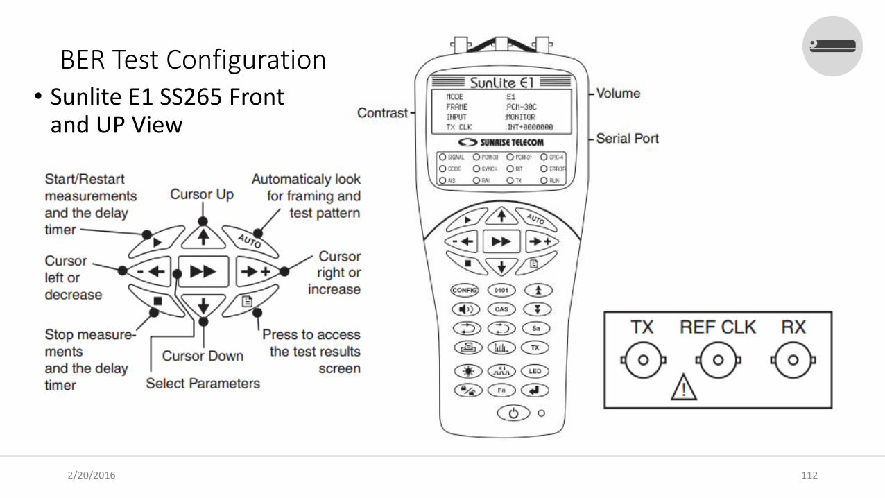
BER Test Configuration • Sunlite E1 SS265 Front
and UP View
2/20/2016 112

BER Test Configuration (2) • Sunlite E1 SS265 LED Panel
Green = receiving pulseRed = Not Receiving pulse
Green = Synch on received test patternRed = Synch is not achieved
2/20/2016 113

BER Test Configuration (3) • Sunlite E1 SS265 Probe Panel
2/20/2016 114

BER Test Configuration (4) • Step To Setting Parameter and Testing
Choice mode:N x 64 = Time selectionE1 = Full 2048 Mbps
Use Selected Time Slot
Unused TS
TS Selection1 1b
2
2
PCM-30PCM-30-CPCM-31PCM-31CUNFRAMED
TERMHI-ZMONITOR
3
2/20/2016 115

BER Test Configuration (5) • Step To Setting Parameter and Testing (2)
INTERNALIN+/-XXXXXEXTERNALRECEIVED
3b
2e15, 2e9, 2e11, 2e23, 1111, 0000,1010, RICAR 3, User 1, User 2, User 3, LIVE,LOOP
45
2/20/2016 116
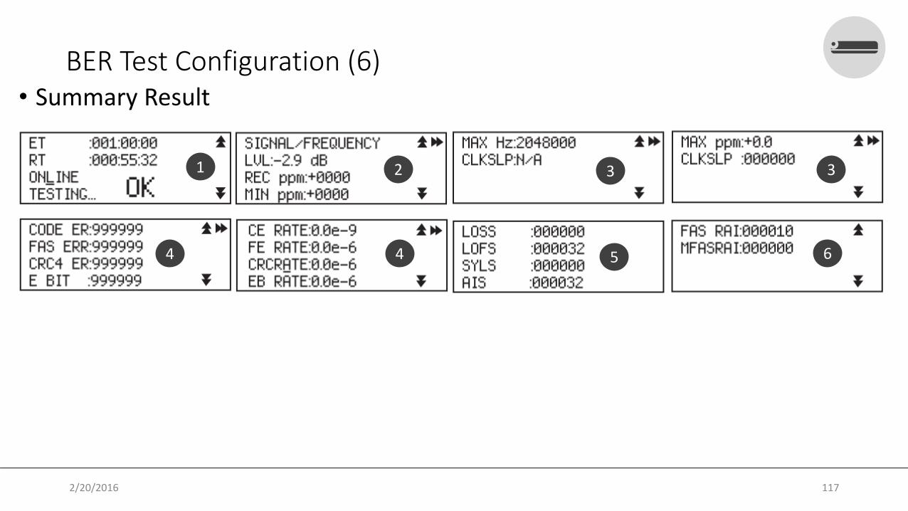
BER Test Configuration (6) • Summary Result
1 2 3 3
4 4 5 6
2/20/2016 117

Use Case• Topology
Node-ANode-B
MPLS Cloud
Modem
SDH Equipment(OMS/OMUX/DXC)
SDH Equipment(OMS/OMUX)
DDF
2/20/2016 118

VPWSCPIPE / CES
QA
2/20/2016 119

THANK YOU@achyarnurandihttp://achyarnurandi.net
2/20/2016 120