
TDI-BROOKS GEOTECHNICAL TOOL KIT · TDI-Brooks offers offshore, nearshore, and inland marine...
30
TDI-Brooks Geotechnical Tool Kit 1 TDI-BROOKS GEOTECHNICAL TOOL KIT TDI-Brooks International, Inc. offers a comprehensive suite of geotechnical analytical services for characterizing offshore geotechnical samples. In addition to our offshore geotechnical sampling toolkit, TDI-Brooks can provide soil testing services through our in-house geotechnical laboratory. Our Geotechnical Toolkit provides high-quality soil samples and in-situ data from the following tools: • 0.5m and 1m Box Core • 6 and 9m Piston Core • 20m Jumbo Piston Core • Cyclic T-Bar • 40m CPT Stinger (PCPT) • 10m Gravity CPT (PCPT) • 40m Stinger Sampler (Shelby Tube) • Miniature Vane System
Transcript of TDI-BROOKS GEOTECHNICAL TOOL KIT · TDI-Brooks offers offshore, nearshore, and inland marine...

TDI-Brooks Geotechnical Tool Kit 1
TDI-BROOKS GEOTECHNICAL TOOL KIT TDI-Brooks International, Inc. offers a comprehensive suite of geotechnical analytical services for characterizing offshore geotechnical samples. In addition to our offshore geotechnical sampling toolkit, TDI-Brooks can provide soil testing services through our in-house geotechnical laboratory. Our Geotechnical Toolkit provides high-quality soil samples and in-situ data from the following tools: • 0.5m and 1m Box
Core • 6 and 9m Piston Core • 20m Jumbo Piston Core • Cyclic T-Bar
• 40m CPT Stinger (PCPT)
• 10m Gravity CPT (PCPT)
• 40m Stinger Sampler (Shelby Tube)
• Miniature Vane System

TDI-Brooks Geotechnical Tool Kit 2
OVERVIEW
TDI-Brooks offers offshore, nearshore, and inland marine geotechnical survey services using a suite of innovative tools for soil sampling and measurement, including box corers (BC), piston corers (PC), gravity corers (GC), jumbo piston corers (JPC), deep-reaching Shelby tube samplers (SPLR), and piezocone penetrometers including our CPT-Stinger and our Gravity CPT tool (gCPT). Figure 1 compares the soil depth below mudline that each of these tools can reach. All of these tools can fully operate in waters as deep as 4,000 m, and each can be fitted with a USBL transponder for precise lateral targeting. The tools are used to perform specified geotechnical and geologic testing on the soil to determine the pertinent physical properties and geologic interpretations.
Figure 1) TDI-Brooks Marine Geotechnical Sampling Tool Kit
The coring tools can recover continuous high quality undisturbed soil samples from the marine soil bed using a 50x50x50-cm (½-m-deep) or 50x50x100-cm (1-m-deep) box corer, a 3-inch ID piston or gravity corer, or a 4-inch ID Jumbo Piston Corer. Additionally, ASTM-quality piezocone penetrometer (PCPT) data can be collected using our innovative CPT-Stinger and gCPT tools. The CPT-Stinger gathers high quality PCPT data by being inserted to its full tool length into the soil and converting the acquired dynamic data to static values. It then advances its still- logging cone another tool-length into the soil at ASTM standard rates. The gCPT tool rapidly acquires high-quality PCPT data by inserting its cone ballistically into the soil and converting its acquired dynamic data to static values. All dynamically acquired PCPT data are normalized back to static data values using the known rate effect adjustment applied to the instantaneous insertion velocities measured every 2 ms by the tool. So-adjusted dynamic data profiles match static data profiles with negligible deviation, as we have published and proved with years of side-by-side tests.

TDI-Brooks Geotechnical Tool Kit 3
TDI-Brooks also offers an innovative and cost-effective formation soil sampling tool called the Stinger Sampler (SPLR). The basic idea behind the deepwater Stinger SPLR system is to “transport” a Shelby tube down through the soil to acquire undisturbed, geotechnical-quality core samples at depths down to 40 m BML, thus nicely complementing the 0-20m continuous JPC soil samples and the 0-40 m continuous PCPT data. In practice, a Shelby tube sample can be acquired at any specified depth down to 40 m, with each successive deployment of the tool.
The economic benefits of quickly and accurately acquiring from a modest-cost vessel several high-quality geotechnical soil samples and PCPT profiles to 40 m BML are readily apparent. These tools allow more high- quality data to be acquired for a given budget, and affords more areal coverage through rapid deployment, compared to the amount of data obtainable from a much more expensive conventional soil boring. Thus, the TDI- Brooks geotechnical seabed sampling kit of tools helps reduce the overall risks associated with foundation design and installation planning.
BOX CORING (BC) SYSTEM
The TDI-Brooks box coring systems consist of hardware assemblies designed to be rigged together into a working core rig and deployed to the seabed for extracting a standard cubic box core. Such a core is 50cm x50cmx100cm (1-m deep) or 50cm x 50cm x50cm (0.5-m deep) in size.
Our box coring system is designed to be a safe, simple, effective mechanism for acquiring large-volume undisturbed shallow sediment samples from the seabed or lakebed. Such samples are essential for the accurate determination of geotechnical characteristics of submerged sediments, as well as for the assessment of the benthic ecology (infauna) as required in marine environmental impact assessments. Figure 2 is a photo of both sizes of TDI-Brooks box corer.
The sample box of the core rig is fabricated from stainless steel and is clean and smooth to minimize frictional resistance between the box and the sediment. The corers have a adjustable weight capability so that the weight stack can be fine-tuned to suit the different seabed conditions that may be encountered.
Figure 2) TDI-Brooks Half-Meter And One-Meter-Deep Box Coring Rigs

TDI-Brooks Geotechnical Tool Kit 4
The BC system is rigged to the main coring rope with a safety shackle, and then its trigger assembly is set for deployment. The main coring rope is load-tested and regularly inspected with Tuck eye splice termination woven into its loose end. The main winch, main coring rope, and the coring A-Frame is used for deploying and retrieving the box corer. In addition to the deployed hardware, support gear is mounted to the vessel working deck to manage the deployment and retrieval of the coring rig. These include the heel-block assembly and the main sheave from the coring A-Frame. Once the box corer is safely deployed, it is lowered to the seabed while performing the navigation protocols for lateral positioning, and then a core sample is acquired at the client-specified site. Upon retrieval on deck the box corer is secured with the safety pin in the closed position and placed on its stand. The lid is opened and the contents inspected for quality and acceptability of the box core sample. The overlying water is siphoned off (gently as the water level approaches the surface of the mud so as to not disturb the surficial layers) to expose the sediment for sub-sampling, descriptions, and photography. The box corer is typically tilted slightly to one corner to facilitate pooling of the last amounts of water. A picture of the BC system with water being siphoned off is shown in Figure 3.
Figure 3) Siphoning Water From The Top Of A Box Core Sample
The sample is accepted if all the following conditions are met, and re-attempted if not:
• Box core jaws are fully closed and the box core is sealed. Water is not streaming out from the jaws of the closure device.
• Box core lid is closed. • Overlying water in the box core is mostly clear. A box core sample with muddy water indicates a disturbance
of the surficial layers. • Surface of sediment is undisturbed (soil on the lid is disturbed by definition), not tilted, slumped or washed-
out. A sample with a tilted surface (corer sticking at an angle less than perpendicular to the sediment surface) may be used with the appropriate precautions.
• Soil sample depth is greater than the minimum required.
For each cast or drop of the box corer, the following information is recorded on the sample log sheet and the sample labels:
• Date and time on bottom • Water depth (wire indicator and fathometer) • Site or Station Number, • Penetration Depth (distance of sediment surface from lid of corer; soil sample depth is calculated from this) • Pertinent comments regarding quality, etc. A brief description of the sediment surface noting texture, color,
depth of loose surface layer, and any life seen for each box core. • Digital photographs are taken of surface of representative box cores. Photographs are taken of any unusual
surface features.

TDI-Brooks Geotechnical Tool Kit 5
After the box corer is retrieved on board and is secured in its stand (Figure 4), Minivane (Figure 5) and/or T-bar (Figure 6) testing is conducted at vertical intervals as specified by the client. Minivane readings are recorded on the Laboratory Sample Sheet along with a description of the box core sample. The least disturbed part of the core sample is typically sub-sampled with push-core tubes (Figure 7). The bottom ends of these push-core tubes are pre-beveled to produce a cutting edge no larger diameter than the ID of the tube. The sub-sampling tubes are placed approximately 2 inches apart. A digital photograph is taken.
Figure 4) Processing the Box Core
The bottom and top of the tubes are then capped immediately (the bottom capped before extraction from the body of soil in the rig). The tops and bottoms of the tubes are marked and the tubes are labeled. The tubes are stored and secured in a vertical position in a manner that minimizes vibrations and bumping. All tube and bulk samples are delivered to the onshore geotechnical testing laboratory in a timely, uninterrupted, temperature-controlled manner after completion of the coring activities.
Figure 5) Miniature Vane On Box Core And Torvane

TDI-Brooks Geotechnical Tool Kit 6
Figure 6) T-Bar Measurements On Box Core
Figure 7) Box Core Sub-Sampled With Push-Core Tubes

TDI-Brooks Geotechnical Tool Kit 7
MINIATURE VANE SYSTEM
The TDI-Brooks miniature vane instrument measures the torque and rotation at a vane shaft using the conventional ASTM method calibrated torque spring set and potentiometer, respectively. Its operation consists of inserting the vane into the soil sample and rotating it at a constant rate to determine the torque required to cause a cylindrical surface to be sheared by the vane. The torque is converted to a unit shearing resistance (shear strength) of the cylindrical surface area. The shear strength reported is the peak strength determined from the torque vs. rotation plot. In addition to the peak shear strength, the residual strength is determined from the same plot if the failure is not dominated by cracking of the sample. In the analysis of vane tests, it is assumed that a cylinder of sediment is uniformly sheared around the axis of the vane in an undrained condition with cohesion as the principal contributor to shear strength.
The standard motorized vane apparatus rotates at a constant rate of 10° per minute and includes the standard 0.5” x 0.5” (12.7 x 12.7-mm) vane. The special ASTM version S2301 has a speed of rotation at the faster rate of 60 to 90° per minute to conform to ASTM D4648 and is supplied with the alternative vane measuring 1" x 1" (25.4 x 25.4mm). Load on either version is applied through one of the 4 calibrated springs supplied. These springs are kept recently calibrated and a certificate of such is provided. A second calibrated spring set is provided for backup. The serial number of the spring set in service is recorded on each datasheet. Figure 8 is a photo of one of our Minivane instruments, calibrated torque spring sets, and vanes ready for service.
Figure 8) TDI-Brooks Minivane System, Ready For Service

TDI-Brooks Geotechnical Tool Kit 8
AUTO T-BAR SYSTEM
The TDI-Brooks Auto T-Bar instrument measures the progressive resistance of a soil column to a cylindrical rod (shaped as an upside-down T) as it advances down the soil column at a constant and standard rate of travel. The instrument is shown in Figure 9, with its T-bar protruding below.
Operation consists of mounting the instrument onto a box corer containing an undisturbed seabed soil sample, connecting the instrument to a shipboard source of compressed air, and starting the automatic advance of the T- Bar into the soil sample. The resistance of the soil is automatically logged during the downward advance until the bottom of the soil sample is reached by the T-bar. The instrument then reverses T-bar movement and logs the soil resistance generated during the upward, retracing return of the T-bar back up to any desired soil depth or to the surface. This sequence of a downward stroke followed by upward re-trace through the failed soil can be continually repeated as many times as desired. Sets of 10 to 30 such cyclic T-bar tests are typical in box cores.
Figure 9) TDI-Brooks Auto T-Bar

TDI-Brooks Geotechnical Tool Kit 9
The instrument measures and logs the soil’s resistive force on the T-bar 10 times per second. The T-bar typically auto-advances at 2.0 cm/sec, so a data set is logged every 2 mm of penetration (this standard rate of advance can be changed to address differing client specifications). A single down-stroke test to 100 cm soil depth thus takes 50 seconds with 500 resistive force measurements logged (Table 1). The resistive force is reported in pounds or newtons, and is converted by the processing program into units of pressure (ksf or kPa) by dividing by the cylindrical cross-sectional area of the T-Bar. The standard (medium) T-Bar cylinder diameter is 1.00 in. and its length is 5.00 inches. Smaller T-bars (0.75 in. and 0.50 in. dia.) are also available for quick change-out, each with cylinder length 5 times its diameter. The push rod is sleeved, rendering its frictional drag during advance in either direction to have no measureable component. The calibrated range of the tool is -100 lb (445 N) upstroke to +100 lb downstroke, which translates using an Nt-bar of 10.5 to maximum measureable undrained shear strengths of about 275 psf (13.2 kPa) using the large bar, 500 psf (23.9 kPa) for the medium bar, and 1,100 psf (52.7 kPa) for the small bar. An example of 30 cyclic auto T-bar measurements into a 1m deep box core sample are plotted in Figure 10.
In this figure, the pink trace represents the initial downward stroke of the T-bar into the soil. The two (right and left) nested sets of blue traces are the subsequent progressive upstroke and downstroke data, with the inner traces being the 30th and final stroke set. All measurements have been converted using an Nt-bar of 10.5 to represent undrained shear strength. This plot illustrates the progression of soil reworking toward fully remolded character during the course of the 30 sets of strokes. Such a data set can thus be also used to project fully remolded values at selected soil depths.
Figure 10) Example Plot Of Auto T-Bar Cyclic Data

TDI-Brooks Geotechnical Tool Kit 10
Table 1. Auto T-Bar Specifications

TDI-Brooks Geotechnical Tool Kit 11
PISTON CORING (PC) SYSTEM
The TDI-Brooks 3-inch-diameter piston coring (PC) system consists of various hardware assemblies designed to be safely and robustly fastened together into a working core rig and deployed to the seabed for extracting a piston core. Such a core rig can be assembled to be 10 to 40 feet long and is 3 inches in barrel ID. An example of a core rig ready for deployment is shown in Figure 11.
The deployed core rig comprises component assemblies of the core head, the core barrel, the piston, and the trigger system. The core head assembly is made up of a 2,000 lb lead-weighted core head with nosepiece and a coupling with which to attach lengths of core barrel sections. It also has a lifting flange assembly that attaches to the trigger system. The trigger assembly is made up of the trigger pendant, trigger arm, pendant clamp, trigger weight, trigger wire, and trigger wire connecting system. The core barrel assembly is made up of selected lengths of core barrel sections, connecting collars, a core liner inside the barrel assembly, a core catcher, a core cutter, and set screws to hold the barrel assembly together. The barrel length can be adjusted in 5-foot increments by adding 5 or 10-ft barrel sections and connecting collars. The rig shown in Figure 11 has a barrel that is 20-ft long, using one 10-ft barrel section and one 5-ft barrel section, and with the uppermost 5 ft of barrel built inside the core head. The extended piston corer (XPC) employs an additional barrel section and a longer trigger pendant.
The main winch, main-line coring rope, and the PC coring A-Frame are used for deploying and retrieving the 3-in. piston core rig on TDI-Brooks vessels. In addition to the deployed hardware, several assemblies are mounted to the vessel working deck to manage the deployment and retrieval of the coring rig. These assemblies include the main sheave from a starboard or port-side coring A-Frame, as well as core-head and trigger tugger winches with their hydraulic power pack.
Figure 11) TDI-Brooks 3-Inch Piston Coring Rig

TDI-Brooks Geotechnical Tool Kit 12
We also have a deployment system for use on 3rd-party vessels not having a provision for a side-mount A-frame. This system includes a stern deployment track in addition to the kit described above. A schematic with dimensions is shown in Figure 12. A photo of the system in operation on a 3rd-party vessel is shown in Figure 13.
Figure 12) TDI-Brooks 3-Inch Piston Coring Track For 3rd-Party Vessels
Figure 13) TDI-Brooks 3-Inch Piston Coring Track On A 3rd-Party Vessel.

TDI-Brooks Geotechnical Tool Kit 13
A piston corer uses a free fall of the coring rig to achieve the desired initial force on impact, and a sliding piston inside the core barrel to reduce inside wall friction with the sediment and to assist in the rapid evacuation of displaced water from the top of the corer. These elements act in concert to maximize core recovery. It uses a trigger assembly to release and allow the corer to free-fall with the core barrel tip starting just above the seabed. The impact speed of the piston corer into the bottom is independent of the winch payout speed. Proper pendant and trigger wire lengths, as well as stopping the winch payout upon trigger, are critical for the proper action of the piston within the barrel. The sequence of piston coring events is shown in Figure 14.
Figure 14) Schematic Of A PC Or JPC Operation At The Seabed
Referring to the schematic: As the corer nears the bottom (A), the winch payout speed is slowed and preparations are made to stop the payout at the instant of release. As the trigger weight impinges the seabed (B) the weight is released from the trigger arm, and the trigger arm begins to rise with respect to the rig. At this point, the core barrel tip is still above the seabed. When the trigger arm has risen through its full travel (C), the corer is mechanically released to free-fall down through the seabed. At this point, the barrel tip of the corer is just above the seabed, as programmed by the proper length of the trigger wire. The moment of release is noted by the Winchman as a sudden drop in main line tension. At the instant of release the payout of the winch is stopped, thus fixing the length of coring rope out. The corer separates from the trigger assembly and free-falls through the seabed, penetrating the upper several meters of sediment. When the falling core rig reaches the end of its pendant slack, the internal piston stops moving downward along with the core rig (D) and becomes fixed with respect to its height about the seabed. The still-falling core barrel then creates suction (much like a syringe and its plunger) between the piston and the soil entering the barrel, enhancing the distance the soil sample will move up the barrel.
The length of the trigger wire, the length of the pendant, and the halting of the rope payout are in concert such that the main rope becomes taut just as the core cutter at the bottom of the barrel comes within a few inches of the seabed. This results in a core with about a few inches of water head between the bottom of the piston and the soil surface inside the liner. When downward momentum of the core has stopped with complete penetration, a slow pullout on the winch is begun. At the initial stage of pullout, the piston slowly moves to the top of the core barrel in response to the Winchman’s tension on the core wire. The piston has a built-in check valve so that water can pass through it when it is moving at slow speed (E). It fetches up against the stop in the core head, and the corer is pulled from the seabed.

TDI-Brooks Geotechnical Tool Kit 14
Retrieval after pullout can proceed as fast as the winch is capable. Winch speed is typically 60 to 80 meters of line per minute. The piston prevents washout of the sample from the top, and the core catcher prevents the sample from backing down out of the barrel tip. In extremely sandy areas, if core material is lost during the retrieval process, typically a “sock” is put in the core cutter to act as a one-way valve, and re-sampling at the site is performed in an attempt to obtain greater recovery.
A picture of the core rig barrel end with the cutter and catcher removed to show the internal piston protruding is shown at left in Figure 15. The core liner inside the barrel is visible. At right the installed cutter/catcher/piston assembly is shown. To rig the PC system, a load-tested PC pendant is inserted with one end hanging out the bottom of the core barrel and the other end hanging out the top of the core head. A piston pin is installed to connect the bottom end of the pendant to the piston (the pin is barely visible in the photo), and then the piston, catcher, and core cutting shoe are mounted to the bottom end of the core barrel with set screws.
Figure 15) Barrel End Of The PC Rig With Piston Showing
The trigger assembly is attached to the top 3 ft section of the pendant by clamping the trigger assembly bar on the pendant, and then properly configuring and securing the trigger assembly to the core head assembly. The system is rigged in such a way that the pendant wire rope will come out of the core head with the proper amount of extra loop available, as dictated by the core barrel length and soil strength at that location. This results in programming a free-fall loop in the pendant of precise distance.
All of the described lifting/rigging gear is regularly load tested and inspected. The main coring rope have a load- tested and inspected Tuck eye splice termination woven into its loose end. The pendant is connected to this termination using a pendant pin. This assembly is designed to roll through the sheave and heel block. For this reason, a rope thimble is not used in the termination loop, because the roll-thru-the-sheave acts with the thimble to incrementally cut and wear the rope over time.
The main winch, main coring rope, and the port A-Frame are used for deploying and retrieving PCs. In addition to the deployed hardware, several assemblies are mounted to the vessel working deck to manage the deployment and retrieval of the coring rig. These include the track/bucket/heel-block assembly, the main sheave from the port A-Frame, and the core head and trigger tugger winches with their hydraulic power pack.
Safety precautions are paramount in our coring procedures and are regularly reinforced through safety meetings, JSAs, toolbox meetings, and other elements of our Safety Management System.
The following is a summary of our PC sample processing procedures:
Upon core retrieval, the core liner is removed, carefully carried and placed in the processing trough, and cut into 3- foot lengths. The core liner is marked with a water proof marker into 3foot long lengths, starting with the top section. For PCs, the top section is a 3-ft section because the top-most sediment is very soft and a short section is difficult to handle and to measure for soil strength. (NOTE: these cores will virtually always have one short or long “odd” section, due to recovery length not being an exact multiple of 3 ft. The short section of a JPC will be the top section, whereas the odd section of a PC will be the bottom section.) Each section is numbered with a Section Number and an arrow pointing to the top.

TDI-Brooks Geotechnical Tool Kit 15
The bottom end of the section is capped immediately after cutting. The top and bottom of the liner section are marked as outlined in a Field Sediment Testing Protocol. This information is recorded immediately in the Core log. Any smell of hydrogen sulfide (rotten egg smell) is noted on the log.
A digital photograph is taken and a visual description of each section is recorded. Lab testing as outlined in the Field Sediment Testing Protocol is performed and the top of the core section is capped. Top and bottom caps are securely taped to the liner. The core sections are stored and secured in a vertical position with the deeper portion of the section on the bottom. The core sections are stored in a manner to minimize individual movement with vessel heave, pitch, and roll. After completion of the coring activities, the core sections are delivered to the onshore geotechnical testing laboratory in a timely, uninterrupted manner.
JUMBO PISTON CORING (JPC) SYSTEM
The TDI-Brooks jumbo piston coring (JPC) system consists of various hardware assemblies designed to be fastened together into a working core rig and deployed to the seabed for extracting a “jumbo” piston core. Such a core rig can be assembled to be 34 to 64 feet long and is 4 inches in barrel ID (Figure 16). The deployed core rig comprises assemblies for the core head, the core barrel, the piston, and the trigger system. The core head assembly is made up of a 5,000 lb lead coring weight with an inserted flange-barrel and coupling with which to attach lengths of core barrel in 5 and 10 ft. sections. It also has a lifting assembly that attaches to the trigger system. The core barrel assembly is made up of selected sections of core barrel, connecting collars, a core liner assembly inside the barrel assembly, a core catcher, a core cutter, and set screws to hold the barrel assembly together. The barrel length can be adjusted in 5-foot increments by adding these barrel sections and connecting collars.
Figure 16) TDI-Brooks Jumbo Piston Coring Rig
TDI-Brooks Geotechnical Tool Kit 16
The trigger assembly is made up of the trigger pendant, trigger arm, pendant clamp, trigger weight, trigger wire, and trigger wire connecting system. The assembled core rig weighs between 5,500 and 7,500 lb, depending on the length of core to be acquired. The weight of the core head is adjusted by adding weight as lead ingots to a starting weight of about 5,000 lb.
The TDI-Brooks extended jumbo piston coring (XJPC) system consists of various hardware assemblies designed to be fastened together into a working core rig and deployed to the seabed for extracting an even longer piston core. Such a core rig can be assembled to be 74 feet long and is 4 inches in barrel ID. This additional length is made possible by adding track extensions to the forward end of the track. These extensions can be quickly removed and secured for core processing.
The main winch, main-line rope, and the stern A-Frame are used for deploying and retrieving the JPC rig. In addition to the deployed hardware, several assemblies are mounted to the vessel working deck to manage the deployment and retrieval of the coring rig. These assemblies include the main sheave from the stern A-Frame and the deployment, retrieval and trigger tugger winches with their hydraulic power pack.
As the JPC trigger weight impinges the seabed and the trigger arm rises, the corer is released to free-fall into the seabed. At the moment of release, the payout of the winch is immediately stopped, thus fixing the length of coring rope out. The corer separates from the trigger and free-falls the mechanically-programmed distance into the seabed. The piston is set to stop moving vertically down when it is just above the seabed, but the core barrel continues to move down into the sediment.
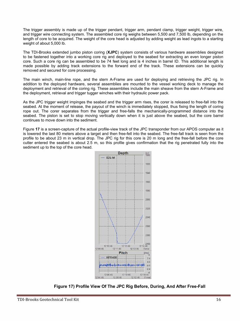
Figure 17 is a screen-capture of the actual profile-view track of the JPC transponder from our APOS computer as it is lowered the last 80 meters above a target and then free-fell into the seabed. The free-fall track is seen from the profile to be about 23 m in vertical drop. The JPC rig for this core is 20 m long and the free-fall before the core cutter entered the seabed is about 2.5 m, so this profile gives confirmation that the rig penetrated fully into the sediment up to the top of the core head.
Figure 17) Profile View Of The JPC Rig Before, During, And After Free-Fall

TDI-Brooks Geotechnical Tool Kit 17
Once the rig settled into the seabed in this example, we logged position for a minute, and then extracted the rig. This sequence can also be seen in the profile view of the figure. Once we confirmed that the rig is fully out of the seabed the Winchman increased winch speed and retrieved the rig. We have learned from experience that our JPC rig will sometimes “glance off” of stiff sediments on gradients more than about 22° from horizontal, so our policy is to make coring attempts into seabed gradients of 20° or less.
A step-wise photo sequence of a JPC rig in operation is presented as Figure 18. This sequence proceeds across the first row, then across the second row, and so on.
Figure 18) Stepwise Process Of JPC Operations

TDI-Brooks Geotechnical Tool Kit 18
Each photo in the 15 frame photo sequence above represents the following: Deployment:
(1) Loading core liner, (2) Pulling the rig sternward down its track, (3) Rotating the rig vertically into the water off the stern, and (4) Installing the trigger,
Retrieval: (5) Securing the trigger pendant into its socket on the bucket to remove the trigger arm, (6) Retrieving the trigger weight, (7) Retrieving the core rig to the surface (it is now hanging on the bottom of the pendant), (8) Aligning the core rig with its bucket using the A-frame and main winch, (9) Securing the core rig into its bucket, (10) (11) & (12) Extracting the core rig and its bucket from vertical to horizontal, (13) Reaching the stop on the track, (14) Removing the core cutter shoe at the bottom of the rig, and (15) Extracting the core inside the core liner.
The JPC system is rigged by inserting a load-tested JPC pendant with the eye end hanging out the bottom of the core barrel and the double pronged jaw end hanging out the top of the core head. The piston pin is installed to connect the eye end of the pendant to the piston within the pre-assembled piston/cutter/catcher assembly, and then the piston/cutter/catcher assembly is mounted to the bottom end of the core barrel with set screws. The trigger assembly is attached to the pendant by unscrewing the knurled-nut cap of the pendant pin, placing the trigger assembly eye in the jaw, inserting the pendant pin through to capture the trigger assembly eye, and re- tightening the knurled-nut cap. The system is rigged in such a way that the pendant wire rope would come out of the core head with the proper amount of extra loop available, as dictated by the core barrel length and soil strength at that location. This resulted in programming a free-fall loop in the pendant of precise distance.
Having a precisely known and repeatable free-fall loop is important because the recoil of the main rope upon trigger must also be taken into account. This is done by adjusting the trigger wire length in relation to the pendant loop. Lengths of pendant and trigger wire are specified for each barrel length, but the trigger wire length is adjusted ±1 to 3 ft as coring continued and a knowledge base is built from subsequent sites, in order to fine-tune the mechanical programming of the rig for optimum core recovery and quality. The length of pendant and trigger wire used for each coring attempt is logged.
The main winch, main coring rope, and the stern A-Frame is used for deploying and retrieving JPCs. In addition to the deployed hardware, several assemblies are mounted to the vessel working deck to manage the deployment and retrieval of the coring rig. These assemblies included the track and stern platform, the main sheave from the stern A-Frame, and the deployment, retrieval, and trigger tugger winches with their hydraulic power pack module. Safety precautions are paramount in our collection procedures and are regularly reinforced through safety meetings, JSAs, tool box meetings, and other elements of our Safety Management System.
A safety zone is established during deployment and retrieval as illustrated with yellow-highlighting in Figure 19. During deployment and retrieval when the main line is under load, no one is allowed to occupy a position in the yellow-shaded zone. At all other stages of the JPC process only the 5-man deck staff is allowed on the back deck aft of the anteroom just foreword of this yellow-highlighted zone.
Figure 19) Safety-Restricted Area During Deployment/Retrieval Operations

TDI-Brooks Geotechnical Tool Kit 19
CORE PROCESSING
Torvane and Miniature Vane measurements are typically conducted on BCs, PCs, and JPCs in the field and remolded Miniature Vane are typically conducted in the onshore lab. In summary:
• After a PC or JPC is acquired, each section is cut and the bottom cap taped to the liner on the selected
section. (NOTE: these cores virtually always have one short or long “odd” section, due to recovery length not being an exact multiple of 1 meter. The short (or odd) section of a JPC is the top section, whereas the odd section of a PC is the bottom section.) A digital photograph is taken and a visual description of each section is recorded. The shear strength of the sediment in the top of each liner is obtained with a Torvane and then with a Miniature Vane tool, as well as in the bottom of the deepest core section. The serial number of the spring set in service is recorded on the in-service Minivane data sheet. On some samples, identified by the client representative, moisture content, unit weight (density), and remolded miniature vane tests are also conducted offshore. Unit weight tests are conducted using TDI-Brooks’ syringe method. The quantity of moisture content tests and unit weight tests conducted offshore is limited by oven space. After testing is completed, sediment samples are typically removed from the test depths in sufficient quantity to conduct moisture content, Atterberg limit, and remold tests during subsequent onshore geotechnical testing. This equates to the top 3 inches for JPCs and the top 4 inches for PCs. The resulting gap is then filled and the core section in its liner is capped and taped in an air-tight manner. The bag is air tight sealed. Both the liner and bag are labeled according to the protocols in Table 2.
• After a BC or XBC is acquired, a digital photograph is taken, a visual description is recorded, and the shear
strength of the sediment vertically through the core is obtained with a Miniature Vane tool at 4-vertical-inch (10-cm) spacing while still in the box, unless instructed otherwise by the client rep. The serial number of the spring set in service is recorded on the active Minivane data sheet. If specified by the client, the T-bar test is run in a zone of undisturbed soil away from the Miniature vane testing. After field testing is completed, a total of three or four push-core sections are sampled using 3-in. or 4-in. diameter tube samplers. These push core sections have their void spaces filled, capped, taped in an air tight manner, and labeled according to the protocols in Table 2.
Processed core sections are stored vertically with the top end up in a cool, temperature controlled environment and secured in order to minimize potential for sample disturbance pending their careful offload at the next port call. Upon demobilization, the core samples are carefully offloaded from the vessel by hand and/or by crane/forklift into an enclosed, refrigerated truck, secured on a padded base against shifting during transit, and carefully transported to the specified Geotechnical Lab for a detailed lab testing program.

TDI-Brooks Geotechnical Tool Kit 20
Table 2. Field Sediment Testing and Protocol
CORE ACCEPTANCE CRITERIA
Table 3 lists the acceptance criteria for penetration and recovery of each type of core. A second coring attempt is made when these criteria are not met, unless the Client’s Technical Rep and the Party Chief agreed that information and/or soil from the site adequately explains the decreased penetration and/or recovery. Adjustments to the tool are possibly made for such a second attempt. A second attempt is also made if the coring gear clearly malfunctioned on the first attempt regardless of apparent penetration and recovery.

TDI-Brooks Geotechnical Tool Kit 21
Table 3. Core Acceptance Criteria
Tool Tool length Minimum Expectation Maximum Expectation Remark Penetration Recovery Penetration Recovery
PC
20 ft (6.1 m)
18 ft
80% of penetration
20 ft
98% of penetration
If geophysical data or the sediments recovered in the core do not clearly
explain the reduced penetration another
attempt will be made. XPC
30 ft (9.1 m)
27 ft
70% of penetration
30 ft
90% of penetration
If geophysical data or the sediments recovered in the core do not clearly
explain the reduced penetration another
attempt will be made.
JPC
64 ft (19.5 m)
56 ft
80% of penetration
64 ft
95% of penetration
If the geophysical data or the sediments recovered in the core do not clearly
explain the reduced penetration another
attempt will be made.
XJPC
74 ft (22.6 m)
65 ft
70% of penetration
74 ft
90% of penetration
If the geophysical data or the sediments recovered in the core do not clearly
explain the reduced penetration another
attempt will be made.
BC
1.65 ft (0.5 m)
1.1 ft (0.33 m)
1.0 ft (0.3 m)
1.65 ft (0.5 m)
1.5 ft (0.46 m) • Bottom
sealed • Water on top
clear • Surface
sediments undisturbed
If the geophysical data or the sediments recovered in the core do not clearly
explain the reduced recovery, or the bottom
is not sealed or the water on the sediments is not
clear, or the surface sediments are disturbed another attempt will be
made. XBC
3.3 ft (1.0 m)
2.3 ft
2.0 ft
• Bottom
sealed • Water on top
clear • Surface
sediments undisturbed
3.3 ft
3.2 ft
• Bottom
sealed • Water on top
clear • Surface
sediments undisturbed
If the geophysical data or the sediments recovered in the core do not clearly
explain the reduced recovery, or the bottom
is not sealed or the water on the sediments is not
clear, or the surface sediments are disturbed another attempt will be
made.

TDI-Brooks Geotechnical Tool Kit 22
CPT-STINGER SYSTEM
The CPT-Stinger (Figure 20) is installed using a JPC core-head, deployed and triggered with the well-proven TDI- Brooks JPC process, and allowed to free-fall ballistically to insert itself into the sediment like a JPC. Once fully embedded in the seafloor with the resulting reaction force of 22,000+ lb now available, the CPT-Stinger automatically extends its cone rod deeper into the formation at the ASTM and international standard “static” cone advance rate.
The standard Long CPT Stinger cone can be ballistically inserted to about 62 ft BML while gathering dynamic PCPT data, and then advances to about 115 ft (35 m) BML while gathering static PCPT data. The Extended Long CPT Stinger cone can be inserted to about 72 ft BML while gathering dynamic PCPT data, and then advances to about 135 ft (40 m) BML while gathering static PCPT data. A discussion of dynamic PCPT data is presented after the tool specifications.
The additional length of the extended tool is made possible by adding track extensions to the forward end of the track so that 10 additional feet of tool barrel may be added. These 10 additional feet of barrel allow 20 additional feet of cone penetration because the extended rod is essentially as long as its longer barrel, so a doubling is achieved with the telescoping process. In-situ PCPT data can thus be acquired to sediment depths double of that of the barrel length of the tool (or of a same-site JPC).
The CPT Stinger has its own barrel assembly, internal cone rod assembly, control module, and PCPT cone with data logger. The rig is deployed (Figure 21) in the same manner as if acquiring a JPC. After trigger with the cone less than 1 m above the seabed, the cone data continue to be acquired 200 times per second during the 3-second ballistic penetration of the cone into the formation.
After cone penetration to full embedment, the rapid data acquisition continues while the cone is advanced deeper into the formation at a constant standard rate. During this push phase, the probe advances at a controlled ASTM rate of 2.0 cm/s ± 0.5 cm/s. Data from the probe are logged every 0.1 mm as the push progresses at this rate.
Once complete, the system is retrieved to the vessel and data are downloaded from the memory cone for evaluation and analysis. The tool is then readied for the next deployment, typically in less than 20 minutes, making 3 to 5 deepwater deployments per 12-hour day routine.
The tested minimum water depth for the CPT-Stinger is currently 350 m. The tested maximum water depth for the tool is currently 4,000 m.
Specifications of the PCPT Cone are given in Table 4. Specifications of the cone data logger are given in Table 5.
Figure 20) CPT-Stinger

TDI-Brooks Geotechnical Tool Kit 23
Table 4. CPT-Stinger Cone Specifications
1. The cone measures the following at a rate of 200 times/sec for up to 3 hours: a. Tip Resistance qc (ksf and mPa) b. Sleeve Friction fs (ksf and kPa) c. Pore Water Pressure u2 (ksf and mPa) d. Vertical Acceleration (m/sec2) e. Tilt (° from vertical)
2. The cone has a 15-cm2 projected end area and conforms to ASTM International Designation: D 5778-07, Standard Test Method for Electronic Friction Cone and Piezocone Penetration Testing of Soils.
3. The cone sleeve has equal end areas and is inherently compensated. The sleeve load cell is hydrostatically compensated.
4. Cone Tip load cell calibrated capacity is 10,000 lb. The full scale response corresponds to a Tip Resistance (qc) of 620 ksf and corresponding soil shear strength of about 25 ksf. The load cell will survive a force of 15,000 lb without damage. Special 20,000 lb cones are also available for water depths greater than 3,000 and for very stiff soils.
5. Cone Sleeve load cell calibrated capacity is 1,600 lb. The full scale response corresponds to a Sleeve Friction (fs) of 6.6 ksf.
6. Pore Pressure transducer calibrated capacity is 5,000 psi. The full scale response corresponds to a Pore Pressure (u2) of 720 ksf. Special 7,000 psi cones are also available for water depths to 4,000 m.
Table 5. Cone Data Acquisition Specifications 1. The analog-to-digital conversion uses 16-bits for a resolution of 1 in 65,000 counts. 2. The sample rate is 200 samples per second. 3. The memory capacity is 24-hours of data from the six sensors. The memory is non-volatile and will retain
data in the event of a power loss. 4. The start command can be:
a. An operator programmed time, b. An signal from the accelerometer indicating the corer has dropped. c. A combination of a and b.
5. The battery life is a minimum of 4-hours. 6. An interface unit allows the download of the cone data to a laptop computer. The laptop is used to initialize
the cone and document cone and site identification data. 7. A full charge of the battery is achieved in less than 30 min from previous deployment.
Total penetration is a function of barrel length as shown in Table 6. Our current best practice is to insert the rig so that the head protrudes 0 to 2 ft from the seabed. This typically produces a robust mudline indication on the head for confirmation of insertion depth. An on-board accelerometer is used to calculate the exact Stinger embedment depth.
Table 6. Penetration ranges of CPT-Stinger vs. Barrel Length

TDI-Brooks Geotechnical Tool Kit 24
Figure 21) The CPT Stinger Ready For Deployment
DYNAMIC PCPT DATA
The memory cone logging rate allows the acquisition of “dynamic” PCPT data for the 3 seconds of ballistic insertion of the cone into the soil formation. Data are logged during insertion at a rate that allows tip resistance to be measured at soil intervals no longer than 5 cm, even at maximum cone velocities approaching 9 m/s. After cone penetration to full embedment, the data acquisition continues while the cone is advanced deeper into the formation at a constant ASTM rate, generating “static” cone data for the second half of the total cone penetration.
After retrieving the deployed tool and its PCPT cone to the deck, the cone is removed, its active data set downloaded to a laptop computer, and the data are immediately processed into client-ready format. A data processing program is used to first graphically mark important data acquisition events (points in time). These events are the instant of: freefall trigger, seabed insertion, tool first at rest in soil, cone advance start, and cone advance end. From these marked events, the program calculates the cone’s freefall time in water and soil, as well as cone push duration. The program sets baselines for tip resistance, sleeve friction, and pore pressure, by averaging the values logged from each load cell just prior to seabed contact of the cone tip.
The program then integrates the accelerometer data into an instantaneous tool velocity profile. This velocity profile is later used by the program to calibrate dynamic cone data. The program then integrates the instantaneous velocity values into a downward tool travel distance profile. In this manner, a very accurate measure is derived of insertion distance of the cone into the soil formation. From the event times and the travel distance profile, the program then calculates freefall distance through the water, cone depth at rest, cone depth at the start and end of push, and cone push rate.

TDI-Brooks Geotechnical Tool Kit 25
The program then produces a CSV file of the measured static PCPT data from all sensors. This file includes the baseline-zeroed static measurements of tip resistance (qc), sleeve friction (fs) and pore pressure (u2) for the duration of the static cone advance into the soil. Values are reported for every 1.0 cm of cone travel, starting with the known depth of the cone when it started its static advance. The program also produces a CSV file that includes corresponding dynamic data for tip resistance, sleeve friction, and pore pressure during the ballistic insertion into the soil. In this file, each of the baseline-corrected load cell values is individually adjusted for the known velocity effect on the cone readings, and each is reported with its penetration depth recorded every 0.005 sec interval. Changing tool velocity causes a maximum spacing of about 5 cm of travel between measurements.
Plots of these files for all three soil sensors by the processing program are used to evaluate the acceptability of the acquisition prior to moving to the next site. Once each deployment’s raw data file is successfully copied, processed, archived, and determined to be acceptable, the original file still residing in the memory module of the cone is erased, batteries are charged, and the cone system is prepared for a subsequent drop.
Such comparisons between side-by-side static PCPT data (2 cm/sec cone advance) with the rate-adjusted dynamic PCPT data acquired during the tool’s insertion have been remarkably good more than 100 sites in our international database (Figure 22). This figure overlays adjusted dynamic data (NE1-LD) with three sets of same- site static data (NE1-SB, NE1-S, and NE1-L), each acquiring overlapping intervals. The remarkable match of the dynamic data with the three independent sets of static data is so routine now that most clients accept our adjusted dynamic data for engineering design purposes.
Figure 22) Comparison Of Side-By-Side Dynamic And Static PCPT Data Profiles

TDI-Brooks Geotechnical Tool Kit 26
GRAVITY CPT SYSTEM
The purpose of the Gravity CPT Stinger (gCPT) tool is to transport a piezocone penetrometer down to the seabed or lakebed to gather dynamic PCPT cone data from the mud line to 5 m or even 10+ m BML (Figure 23). In addition to its 800 kg driving head with lifting bale and coupling, the rig comprises a self-contained PCPT cone penetrometer that measures tip resistance, sleeve friction and pore pressure using standard ASTM cone protocols. The Gravity CPT system is deployed using the same winch, A-frame, and process as for piston coring. When just above mudline, the tool is triggered like a piston corer to ballistically insert itself into the soil.
Once the cone insertion into the soil is complete less than 3 sec after trigger, the system is immediately retracted from the seabed and retrieved to the deck. Cone data are downloaded from the probe for evaluation and analysis. The tool is readied for the next deployment, typically in less than 5 minutes, making numerous measurements per day feasible, depending only on water depth and winch speed. The maximum water depth for the gCPT is 4,000 m. Current tested minimum water depth for successful operation is 10 m.
As a result, high quality in-situ dynamic PCPT data can be rapidly acquired from the mudline to 10 m BML in a safe, rapid, and very cost-effective manner. We have deployed this tool in a lake from a 35 ft long boat, for example. Data from the probe are logged 200 times per second. This logging rate allows the cone parameters to be measured at sediment intervals no larger than 3 cm even at ballistic velocities approaching 5 m/sec. Parameters so logged include tip resistance (mPa), sleeve friction (kPa), pore pressure (mPa), cone acceleration (m/s2) and cone tilt (°) from vertical. We adjust these dynamic cone data to static CPT data using our database of cone rate effect with soil type. Such comparisons between the static PCPT measurements from the cone push at 2 cm/sec with the rate-adjusted dynamic PCPT data acquired during the tool’s insertion have been remarkably good at all test sites to-date (see above discussion of Dynamic PCPT Data). Multiple “pogo” drops for rapid data acquisition along a route are possible with the 4- hour battery logging capacity before retrieving the tool to deck.
After the tool is retrieved to the deck, the PCPT cone is removed from the coupling end of the driving head and brought to a laptop for data retrieval and processing. The resulting data file is opened with a processing program designed for this system. After opening the raw data file, the program performs an integration and double integration of the accelerometer data. In this manner, a very accurate and reliable measure is derived of freefall distance in the water and freefall distance in the soil, as well as the instantaneous velocities of the cone during penetration into the soil.
The program then calculates the proper Tip Resistance baseline, Friction Sleeve baseline, Pore Pressure baseline, an insertion velocity profile with depth, and the cone depth upon coming to rest from ballistic insertion. This file also includes the baseline-corrected measurements of Tip Resistance, Sleeve Friction, and Pore Pressure for the duration of the cone insertion into the soil. In this file, each of the baseline-corrected cone load cell values is individually corrected for the velocity effect on the cone readings. Effective Tip Resistance values are corrected by the following formula:
Adjusted Tip Resistance =Velocity Correction Factor x Baseline-Corrected Tip Resistance
Dynamic values for Sleeve Friction and for Pore Pressure have their own velocity correction factors. The resulting adjusted data are calibrated by overlaying the dynamic data with existing static data or soil strength data at the same or nearby site. The files are small enough to be emailed from the vessel to the engineers in the office. Graphical representation of the results from a recent gCPT deployment (Figure 24). Tip resistance and sleeve friction values have been adjusted for the rate effect on them, but pore pressure needs no such dynamic data adjustment.
A comparison of gCPT results with same-site box core T-bar and CPT-Stinger re shown in Figure 25. Overlay of derived undrained shear strength from each tool’s data is remarkable.
Figure 23) gCPT Tool

TDI-Brooks Geotechnical Tool Kit 27
Figure 24) Graphical Results From A gCPT Deployment
Figure 25) Comparison Of gCPT Results With Same-Site T-Bar And CPT-Stinger

TDI-Brooks Geotechnical Tool Kit 28
STINGER (SHELBY TUBE) SAMPLER
The high cost of conventionally drilled borings in deepwater limits the number of borings that can be drilled, the number of soil samples that can be collected, and the areal coverage for a given project. To remediate the situation, TDI-Brooks has developed and is now offering an innovative and cost-effective tool called the Stinger Sampler. The basic idea behind the deepwater Stinger Sampler system is to “transport” a Shelby tube down through the seabed to acquire geotechnical-quality core samples down to depths of 20 to 40 m BML, thus nicely complementing the 0-20m continuous JPC soil samples (Figure 26).
The economic benefits of quickly acquiring from a modest-cost vessel several high-quality geotechnical soil samples are readily apparent, in that the Stinger Sampler allows more high-quality data to be acquired for a given budget, and affords more areal coverage compared to the amount of data obtainable from a single, more expensive conventional soil boring. Thus, the Stinger Sampler helps reduce the overall risks associated with foundation design and installation planning.
Figure 26) Schematic Illustration Of The TDI-Brooks Stinger Sampler
The Stinger Sampler system consists of various hardware assemblies designed to be fastened together into a working tool that can be safely deployed to the seabed. The deployed tool is comprised of the weight-head assembly, the USBL transponder canister, the barrel assembly, the push rod assembly, the Shelby tube sampling system, the push control module, and the trigger system, as further described below.
• The weight-head assembly is made up of a core head with an inserted flange-barrel and coupling with
which to attach 10-ft long barrel sections. The weight of the core head can be adjusted by adding or removing lead ingots.
• A USBL transponder is placed into a canister mounted inside the weight-head for monitoring the deployed tool’s lateral position and depth.
• The barrel set can be assembled to a pre-determined length of up to 21 m. • The trigger assembly is made up of the trigger arm, pendant clamp, trigger weight, trigger wire, and trigger
wire connecting system. • The push rod assembly can push the Shelby tube sampling system to 20 m more into the soil, down to 40
m BML. The depth reached by the push is controllable so that a sample can be acquired from two or more depths in the formation with subsequent drops
. The Stinger Sampler operational process is essentially identical to that of the well-proven CPT- Stinger, with the Stinger Sampler tool deployed using the same existing TDI-Brooks CPT-Stinger safe deployment system.
By simply replacing the PCPT cone of the already mobilized TDI-Brooks CPT-Stinger tool with a Shelby tube soil sampling system, the field crew can quickly and safely convert from PCPT acquisition to soil sampling mode. Same-site CPT data and 3-inch diameter, 2 to 3-ft long Shelby tube samples, each acquired down to as deep as 40 m, can be performed at a rate of several drops per day, as the conversion is safe, quick, and simple. Such samples can also be acquired at any client-specified depth, if a particular formation seen on a sub-bottom profile is desired.

TDI-Brooks Geotechnical Tool Kit 29
The Shelby tube sampling system is installed at the end of the CPT-Stinger rod in place of the PCPT cone, deployed and triggered near the seabed with the well-proven TDI-Brooks free-fall tool insertion process, and allowed to ballistically insert itself 20 m down into the soil just like a CPT-Stinger.
During ballistic insertion, no soil fills the Shelby tube as it remains protected inside its housing. Once fully embedded 21 m deep into the soil, the reaction force of 22,000+ lb is available to push the Shelby tube sampling system deeper into the formation (exactly like the PCPT cone of the CPT-Stinger) at a push rate of about 2 cm/sec. During this “static” push, soil flows through the Shelby tube and out its top-vents. When the tool push reaches its stop at the pre-set depth, the soil from that depth inside the Shelby tube is captured by valve closure and retained during retrieval in a materially undisturbed state.
During deployment, as the tool nears the seabed during its water column descent, the winch payout speed is slowed and preparations are made for USBL position logging during the instant of release. As the weight is released from the trigger arm, the trigger arm begins to rise with respect to the tool. When the trigger arm has risen through its full travel, the tool is released to free-fall down into the seabed. At this trigger point, the Shelby tube sampling system in its housing will be one or two feet above the seabed.
At the moment of release, the payout of the winch is stopped, thus fixing the length of main-rope out. The pendant will help stop the tool’s weight-head so that it barely protrudes from the seabed. After this insertion, the Shelby tube sampling system will be extended from perhaps 21 m starting depth to as much as 20 m deeper into the formation. The rate of penetration is controlled at 2 cm/sec, so up to 15 minutes are allowed for this phase. When the rod push stops, the soil residing in the Shelby tube is a high quality sample from that stop-depth. Once the push is completed, a slow pullout on the winch is begun to immediately close a valve at the top of the Shelby tube, and then to extract the extended push rod and the barrel set from the soil. While still vertical at the sea surface, the push rod automatically retracts back into the barrel, and the tool is then retrieved to the deck. Figure 27 shows a schematic of the valve that closes at the onset of tool extraction after its stops pushing deep in the soil.
Figure 27) Valve At The Top Of The Stinger Sampler Shelby Tube
After the tool is on deck, the Shelby tube sampling system is removed from the end of the push rod and brought into the lab for processing. The tool’s data logger is connected to a laptop computer, and then the raw data file generated from the tool’s ballistic insertion is opened for processing the ballistic insertion data into acceleration, velocity, and depth profiles. In this manner, a very accurate and reliable measure is derived of freefall distance in the water and insertion distance in the soil, in an identical fashion as for the CPT-Stinger. Figure 28 is a photograph of a tool just having acquired an undisturbed soil sample from 40 m depth.

TDI-Brooks Geotechnical Tool Kit 30
Figure 28) Photo Of The Stinger Sampler Shelby Tube With A Soil Sample From 40 M Depth
Revised 05/23/2019