TD WATERFLUX NG - CONAUT
51
WATERFLUX 3070 WATERFLUX 3070 WATERFLUX 3070 WATERFLUX 3070 Technical Datasheet Technical Datasheet Technical Datasheet Technical Datasheet IP68 Compact & remote Battery powered electromagnetic water meter • Battery power or optional mains power & battery backup with the FlexPower • Easy installation without straight inlet or outlet lengths • Integrated pressure and temperature sensor © KROHNE 07/2016 - 4005198101 - TD WATERFLUX 3070 - R01 en
Transcript of TD WATERFLUX NG - CONAUT

WATERFLUX 3070WATERFLUX 3070WATERFLUX 3070WATERFLUX 3070 Technical DatasheetTechnical DatasheetTechnical DatasheetTechnical Datasheet
IP68 Compact & remoteBattery powered electromagnetic water meter
• Battery power or optional mains power & battery backup with the FlexPower • Easy installation without straight inlet or outlet lengths• Integrated pressure and temperature sensor
© KROHNE 07/2016 - 4005198101 - TD WATERFLUX 3070 - R01 en
CONTENTS
2 www.krohne.com 07/2016 - 4005198101 - TD WATERFLUX 3070 - R01 en
WATERFLUX 3070
1 Product features 4
1.1 The power of independence ............................................................................................. 41.2 Options.............................................................................................................................. 71.3 Measuring principle........................................................................................................ 10
2 Technical data 11
2.1 Technical data................................................................................................................. 112.1.1 Integrated P&T sensor (optional) ......................................................................................... 172.1.2 KROHNE FlexPower (optional) ............................................................................................. 182.1.3 Modbus protocol (option) ...................................................................................................... 19
2.2 Legal metrology.............................................................................................................. 202.2.1 OIML R49 ............................................................................................................................... 202.2.2 MID Annex III (MI-001)........................................................................................................... 232.2.3 Verification to MID Annex III (MI-001) and OIML R49 ........................................................... 25
2.3 Measurement accuracy.................................................................................................. 262.3.1 WATERFLUX 3070 without straight inlet and outlet sections .............................................. 27
2.4 Dimensions and weights ................................................................................................ 282.5 Pressure loss.................................................................................................................. 302.6 Battery lifetime............................................................................................................... 31
3 Installation 32
3.1 General notes on installation ......................................................................................... 323.2 Intended use ................................................................................................................... 323.3 Pre-installation requirements ....................................................................................... 323.4 General requirements .................................................................................................... 33
3.4.1 Vibration ................................................................................................................................ 333.4.2 Magnetic field........................................................................................................................ 33
3.5 Installation conditions .................................................................................................... 343.5.1 Inlet and outlet ...................................................................................................................... 343.5.2 T-section ............................................................................................................................... 343.5.3 Open feed or discharge......................................................................................................... 343.5.4 Bends .................................................................................................................................... 353.5.5 Pump ..................................................................................................................................... 353.5.6 Control valve ......................................................................................................................... 363.5.7 Air venting and vacuum forces ............................................................................................. 363.5.8 Mounting position and flange deviation................................................................................ 373.5.9 Installation in a metering pit and subsurface applications.................................................. 38
3.6 Mounting ......................................................................................................................... 393.6.1 Torques and pressures......................................................................................................... 39
3.7 Mounting of the signal converter ................................................................................... 423.7.1 Remote converter housing ................................................................................................... 423.7.2 Closing of the converter housing.......................................................................................... 43
4 Electrical connections 44
4.1 Safety instructions.......................................................................................................... 444.2 Grounding ....................................................................................................................... 44
CONTENTS
3www.krohne.com07/2016 - 4005198101 - TD WATERFLUX 3070 - R01 en
WATERFLUX 3070
4.3 Cable overview................................................................................................................ 454.4 Connection of the sensor cable...................................................................................... 464.5 Connection of the signal cable ....................................................................................... 47
4.5.1 IP68 housing (compact version)............................................................................................ 474.5.2 IP68 housing (remote version).............................................................................................. 48
5 Notes 50
1 PRODUCT FEATURES
4
WATERFLUX 3070
www.krohne.com 07/2016 - 4005198101 - TD WATERFLUX 3070 - R01 en
1.1 The power of independence
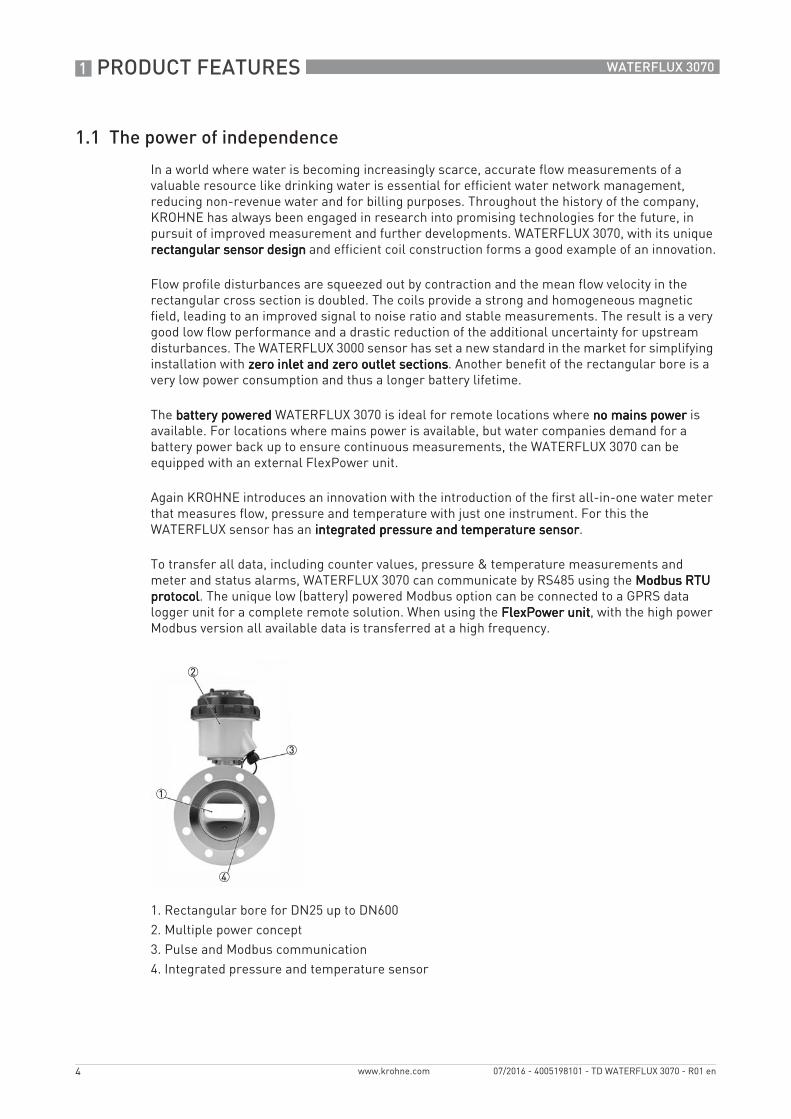
In a world where water is becoming increasingly scarce, accurate flow measurements of a valuable resource like drinking water is essential for efficient water network management, reducing non-revenue water and for billing purposes. Throughout the history of the company, KROHNE has always been engaged in research into promising technologies for the future, in pursuit of improved measurement and further developments. WATERFLUX 3070, with its unique rectangular sensor designrectangular sensor designrectangular sensor designrectangular sensor design and efficient coil construction forms a good example of an innovation.
Flow profile disturbances are squeezed out by contraction and the mean flow velocity in the rectangular cross section is doubled. The coils provide a strong and homogeneous magnetic field, leading to an improved signal to noise ratio and stable measurements. The result is a very good low flow performance and a drastic reduction of the additional uncertainty for upstream disturbances. The WATERFLUX 3000 sensor has set a new standard in the market for simplifying installation with zero inlet and zero outlet sections zero inlet and zero outlet sections zero inlet and zero outlet sections zero inlet and zero outlet sections. Another benefit of the rectangular bore is a very low power consumption and thus a longer battery lifetime.
The battery poweredbattery poweredbattery poweredbattery powered WATERFLUX 3070 is ideal for remote locations where no mains powerno mains powerno mains powerno mains power is available. For locations where mains power is available, but water companies demand for a battery power back up to ensure continuous measurements, the WATERFLUX 3070 can be equipped with an external FlexPower unit.
Again KROHNE introduces an innovation with the introduction of the first all-in-one water meter that measures flow, pressure and temperature with just one instrument. For this the WATERFLUX sensor has an integrated pressure and temperature sensorintegrated pressure and temperature sensorintegrated pressure and temperature sensorintegrated pressure and temperature sensor.
To transfer all data, including counter values, pressure & temperature measurements and meter and status alarms, WATERFLUX 3070 can communicate by RS485 using the Modbus RTU Modbus RTU Modbus RTU Modbus RTU protocolprotocolprotocolprotocol. The unique low (battery) powered Modbus option can be connected to a GPRS data logger unit for a complete remote solution. When using the FlexPower unitFlexPower unitFlexPower unitFlexPower unit, with the high power Modbus version all available data is transferred at a high frequency.
1. Rectangular bore for DN25 up to DN6002. Multiple power concept3. Pulse and Modbus communication4. Integrated pressure and temperature sensor
1
2
3
4

PRODUCT FEATURES 1
5
WATERFLUX 3070
www.krohne.com07/2016 - 4005198101 - TD WATERFLUX 3070 - R01 en
HighlightsAccurate and reliable performance
• Unique rectangular flow sensor design for sizes DN25…600• Flow profile disturbances squeezed out by contraction• Large turn down ratio for peak flows during the day and low flows during the night• Standard in-house wet calibration for every meter• Internal diagnostics and external verification with OPTICHECK tool
Approvals
• Certifications to OIML R49 and MID Annex III (MI-001) up to DN600• Range of local custody transfer approvals based on OIML R49• Drinking water approvals including ACS, DVGW, NSF, TZW and WRAS
Standard IP68 signal converter and sensor
• IP68 compact and field version for submersion in flooded chambers • Compact housing with small footprint for installation in electrical cabinets • Plug & play (IP68) connectors
Simplifies installation, minimises maintenance
• 0D inlet, 0D outlet for compact installation directly behind an elbow or reducer• Special coating for immersed or subsoil sensor installation • Standard reference electrode making grounding rings obsolete
Multiple power concept for any location
• Internal lithium batteries for battery lifetime up to 10 years • External battery pack for longer lifetime• AC mains supply and DC power ( for green energy eg. solar or wind power) both with battery
backup
Flow, pressure and temperature measurement
• Flow, pressure and temperature measurement integrated in one instrument• Simple, cost efficient and tamper proof installation
Data communication and transfer
• RS485 Modbus RTU communication for disclosure of a wide range of data • Special low power Modbus option for battery operation • Preselected brands for GPRS/data logger for data transfer

1 PRODUCT FEATURES
6
WATERFLUX 3070
www.krohne.com 07/2016 - 4005198101 - TD WATERFLUX 3070 - R01 en
Industries• Water distribution network management• District metering (DMA)• Revenue metering• Water abstraction• Other; Irrigation, dewatering
Applications• Measurement of clean potable water, raw water and irrigation water• Monitoring of distribution networks• Pressure and water quality control with integrated P&T sensor• Pressure and pumping stations• District Metering Areas (DMA) for leak detection• Water consumption and billing• Checking of water wells or pumps and maintaining water balance
PRODUCT FEATURES 1
7
WATERFLUX 3070
www.krohne.com07/2016 - 4005198101 - TD WATERFLUX 3070 - R01 en
1.2 Options
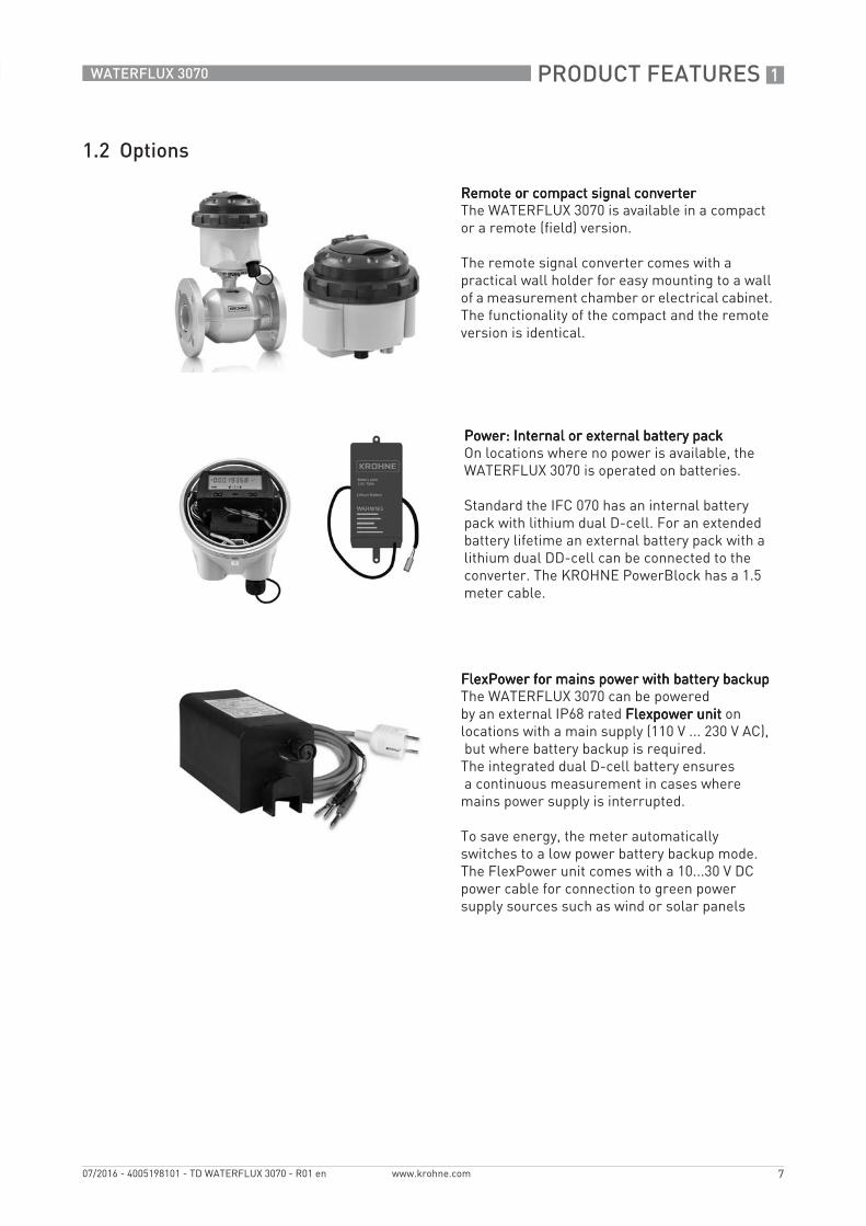
Remote or compact signal converterRemote or compact signal converterRemote or compact signal converterRemote or compact signal converterThe WATERFLUX 3070 is available in a compact or a remote (field) version.
The remote signal converter comes with a practical wall holder for easy mounting to a wall of a measurement chamber or electrical cabinet. The functionality of the compact and the remote version is identical.
Power: Internal or external battery pack Power: Internal or external battery pack Power: Internal or external battery pack Power: Internal or external battery pack On locations where no power is available, the WATERFLUX 3070 is operated on batteries.
Standard the IFC 070 has an internal battery pack with lithium dual D-cell. For an extended battery lifetime an external battery pack with a lithium dual DD-cell can be connected to the converter. The KROHNE PowerBlock has a 1.5 meter cable.
FlexPower for mains power with battery backup FlexPower for mains power with battery backup FlexPower for mains power with battery backup FlexPower for mains power with battery backup The WATERFLUX 3070 can be poweredby an external IP68 rated Flexpower unit Flexpower unit Flexpower unit Flexpower unit on locations with a main supply (110 V ... 230 V AC), but where battery backup is required.The integrated dual D-cell battery ensures a continuous measurement in cases where mains power supply is interrupted.
To save energy, the meter automatically switches to a low power battery backup mode.The FlexPower unit comes with a 10...30 V DC power cable for connection to green power supply sources such as wind or solar panels

1 PRODUCT FEATURES
8
WATERFLUX 3070
www.krohne.com 07/2016 - 4005198101 - TD WATERFLUX 3070 - R01 en
Immersion in water (IP68)Immersion in water (IP68)Immersion in water (IP68)Immersion in water (IP68)Both sensor and signal converter are IP68 rated according IEC/EN 60529 suitable for immersing underwater during flooding (e.g. in periods of heavy rainfall).
The robust WATERFLUX 3000WATERFLUX 3000WATERFLUX 3000WATERFLUX 3000 flow sensor is suitable for long duration immersion in flooded metering pits. The compact and remote version of the IFC 070 signal converter, can be installed in chambers with periodic submersion.The output cable has plug and play IP68 rated connectors. Immersion in water is possible down to a depth of 10 meters.
Underground installationUnderground installationUnderground installationUnderground installationWith its robust construction the flow sensor can also be buried underground. This can be a major cost saving as it eliminates the need for a measurement chamber. To protect the flow sensor a special coating can be ordered as an option. The remote sensor version has an IP68 stainless steel connection box.
Integrated Pressure & Temperature sensorIntegrated Pressure & Temperature sensorIntegrated Pressure & Temperature sensorIntegrated Pressure & Temperature sensorThe WATERFLUX 3070 WATERFLUX 3070 WATERFLUX 3070 WATERFLUX 3070 is the first all-in-one water meter measuring flow, pressure and temperature with just one instrument. For this the WATERFLUX 3000 sensor is equipped with an integrated pressure and temperature sensor. Flow, pressure and temperature values can be read on the display or via Modbus. When critical limits for pressure and temperature are exceeded an alarm can be generated via a status output or Modbus. The integrated pressure and temperature sensor is available for sizes DN50 to DN200.

PRODUCT FEATURES 1
9
WATERFLUX 3070
www.krohne.com07/2016 - 4005198101 - TD WATERFLUX 3070 - R01 en
Data communication options Data communication options Data communication options Data communication options Water companies are looking for more measurement data, smart data, and real time data from water meters located over a wide area. The display forms the main source of data for meters subject to custody transfer (OIML R49, MI-001). Measurement and meter status data can be given out either via 2 pulse and 2 status outputs or via MODBUS RTU. Via its outputs the WATERFLUX 3070 can be connected to a wide range of data logger and remote communication equipment from various brands supporting pulses and or Modbus. Contact KROHNE for a list with preselected brands that have already been tested on their compatibility.
Calibration to OIML R49 and MID MI-001Calibration to OIML R49 and MID MI-001Calibration to OIML R49 and MID MI-001Calibration to OIML R49 and MID MI-001Every single flowmeter is wet calibrated before leaving the factory. For this KROHNE operates a large number of accurate calibration facilities including the world’s most precise volumetric calibration rig for flowmeters.
The WATERFLUX 3070 is approved to MID Annex III (MI-001) and OIML R49. The certification applies for accuracy class 1 and 2, all sizes, and for 0D inlet- 0D outlet. Access to fiscal parameters can be blocked to prevent intervention of non-authorized persons.
OPTICHECK | Tool for on-site verificationOPTICHECK | Tool for on-site verificationOPTICHECK | Tool for on-site verificationOPTICHECK | Tool for on-site verificationThe OPTICHECK provides an inline health check of the meter under test. When the tool is connected on site, it gathers measuring data to ensure that the flowmeter is performing within 1% of its factory calibration. The baseline can be historic repair data from the factory or on-site test results after performing a full verification. A hard copy of the verification report can be printed for every flowmeter. The verification data are digitally stored. Contact KROHNE for more information or for an on-site service visit.
Modbus communication Modbus communication Modbus communication Modbus communication The WATERFLUX 3070 offers two RS 485 Modbus RTU interface options. The low power (non-isolated) Modbus option can be used for data communication between a stand-alone battery operated WATERFLUX 3070 and data logger GPRS module. The high powered (isolated) Modbus option can be used for data transfer between a WATERFLUX 3070 using the FlexPower unit and process automation systems. Modbus offers a simple solution to disclose all available data including measurement data (sum, forward, reverse counters, flow rate), status data (battery lifetime, meter status) and actual values for pressure and temperature.

1 PRODUCT FEATURES
10
WATERFLUX 3070
www.krohne.com 07/2016 - 4005198101 - TD WATERFLUX 3070 - R01 en
1.3 Measuring principle
An electrically conductive fluid flows inside an electrically insulated pipe through a magnetic field. This magnetic field is generated by a current, flowing through a pair of field coils.Inside of the fluid, a voltage U is generated:U = v * k * B * DU = v * k * B * DU = v * k * B * DU = v * k * B * D
in which:v = mean flow velocityk = factor correcting for geometryB = magnetic field strengthD = inner diameter of flowmeter
The signal voltage U is picked off by electrodes and is proportional to the mean flow velocity v and thus the flow rate Q. A signal converter is used to amplify the signal voltage, filter it and convert it into signals for totalizing, recording and output processing.
Rectangular cross sectionRectangular cross sectionRectangular cross sectionRectangular cross section
The minimal height of the measuring tube decreases the distance between the field coils (1), resulting in a stronger and more homogeneous magnetic field (2). In addition, the mean flow velocity v increases due to the rectangular and reduced cross section. The large electrode spacing (D) and the increased flow velocity results in a higher magnetic signal voltage, also in the presence of a low flow rate.
Figure 1-1: Measuring principle
1 Field coils2 Magnetic field3 Electrodes4 Induced voltage (proportional to flow velocity)5 Rectangular cross section

TECHNICAL DATA 2
11
WATERFLUX 3070
www.krohne.com07/2016 - 4005198101 - TD WATERFLUX 3070 - R01 en
2.1 Technical data
• The following data is provided for general applications. If you require data that is more relevant to your specific application, please contact us or your local sales office.
• Additional information (certificates, special tools, software,...) and complete product documentation can be downloaded free of charge from the website (Downloadcenter).
Measuring systemMeasuring principle Faraday's law of induction
Application range Electrically conductive fluids
Measured valueMeasured valueMeasured valueMeasured value
Primary measured value Flow velocity
Secondary measured value Volume flow
Optional measured value Pressure and temperature
DesignFeatures Unique rectangular flow tube design providing improved flow profile and
signal to noise ratio resulting in highest accuracy, low energy consumption and large turndown ratio
Rilsan® polymer coated flow tube approved for drinking water
No internal or moving parts
Built-in reference electrode
Optional; built-in P&T sensor (restricted to DN50...200), refer to Integrated P&T sensor (optional) on page 17
Self-providing energy by batteries for up to 10 years
Modular construction The measurement system consists of a flow sensor and a signal converter. It is available as a compact and as a remote version.
Compact version With IFC 070 converter: WATERFLUX 3070 C
Remote version In field (F) version with IFC 070 converter: WATERFLUX 3070 F
Cable length up to 25 m / 70 ft, other lengths on request
Nominal diameter DN25...600 / 1...24", Rectangular bore
Display and user interfaceDisplay and user interfaceDisplay and user interfaceDisplay and user interface
Display LCD display, 8 digits
Operation 2 optical keys to navigate through the menu of the signal converter without opening the housing.
Display information Standard:Standard:Standard:Standard:
Sum counter (default), forward counter, reverse counter or flow rate
Flow direction (forward or reverse), counter settings
Measured value and measuring unit
Battery lifetime indicator
Optional: Operating pressure, operating temperature, empty pipe, self-test, display test, test mode, diameter, meter constant, software version, AMR mode, warning sign, multiplier
Remote reading Optional: external GSM / GPRS data logger for pulse or ModbusFor preselected data logger brands, please contact KROHNE

2 TECHNICAL DATA
12
WATERFLUX 3070
www.krohne.com 07/2016 - 4005198101 - TD WATERFLUX 3070 - R01 en
MeasurementsMeasuring units VolumeVolumeVolumeVolume
Default setting: m3
Selectable: liter, gallon, imperial gallons, cubic feet, acre inch, acre feet
Flow rateFlow rateFlow rateFlow rate
Default setting: m3 / hr
Selectable: liter/sec, gallon/min, imperial gallon/min, cubic feet/hour, acre inch/day, acre feet/day
Measurement intervalBattery power
Default setting: 15s
Selectable: 5s, 10s, 15s, 20s
Measurement intervalFlexPower
Default setting: 5s
Empty pipe detection Optional: display shows - EP - in case of empty pipe detection
Low flow cut off Measurements below this value are neglected
Default setting: 10 mm/s
Selectable: 0 mm/s, 5 mm/s, 10 mm/s
Measuring accuracyReference conditions Medium: water
Temperature: +10...30°C / +50...86°F
Operating pressure: 1 bar / 14,5 psi
Inlet section: 3 DN / Outlet section: 1 DN
Maximum measuring error DN25...300; down to 0.2% of the measured value ± 1 mm/sDN350...600; down to 0.4% of the measured value ± 1 mm/s
The maximum measuring error depends on the installation conditions.
For detailed information refer to Measurement accuracy on page 26.
Repeatability DN 25...300; ±0.1% (v >0.5 m/s / 1.5 ft/s) DN350...600; ±0.2% (v >0.5 m/s / 1.5 ft/s)
Calibration / Verification Standard:Standard:Standard:Standard:
2 Point calibration by a direct volume comparison.
Optional: Optional: Optional: Optional: for DN25...600
Verification to Measurement Instrument Directive (MID), Annex MI-001. Standard: Verification at Ratio (Q3/Q1) = 80 Optional: Verification at Ratio (Q3/Q1) > 80
MID Annex III (MI-001)(Directive 2014/32/EU)
EC-Type examination certificate to MID Annex III (MI-001)EC-Type examination certificate to MID Annex III (MI-001)EC-Type examination certificate to MID Annex III (MI-001)EC-Type examination certificate to MID Annex III (MI-001)
Diameter: DN25...600
Minimum straight inlet flow: 0 DN
Minimum straight outlet flow: 0 DN
Forward and reverse (bi-directional) flow
Orientation: any
Ratio (Q3/Q1): up to630
Liquid temperature range: +0.1°C / 50°C
Maximum operating pressure: ≤ DN200: 16 bar, ≥ DN250: 10 bar
For detailed information refer to Legal metrology on page 20.
TECHNICAL DATA 2
13
WATERFLUX 3070
www.krohne.com07/2016 - 4005198101 - TD WATERFLUX 3070 - R01 en
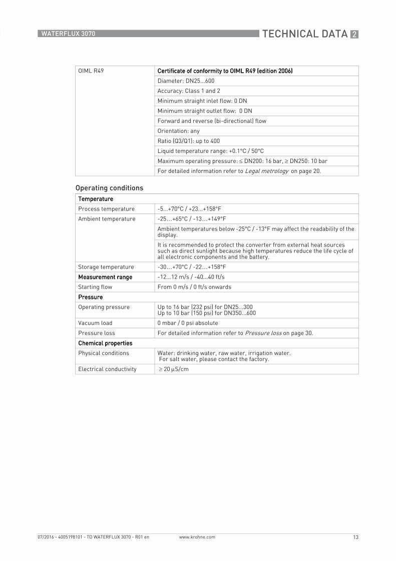
OIML R49 Certificate of conformity to OIML R49 (edition 2006)Certificate of conformity to OIML R49 (edition 2006)Certificate of conformity to OIML R49 (edition 2006)Certificate of conformity to OIML R49 (edition 2006)
Diameter: DN25...600
Accuracy: Class 1 and 2
Minimum straight inlet flow: 0 DN
Minimum straight outlet flow: 0 DN
Forward and reverse (bi-directional) flow
Orientation: any
Ratio (Q3/Q1): up to 400
Liquid temperature range: +0.1°C / 50°C
Maximum operating pressure: ≤ DN200: 16 bar, ≥ DN250: 10 bar
For detailed information refer to Legal metrology on page 20.
Operating conditionsTemperatureTemperatureTemperatureTemperature
Process temperature -5...+70°C / +23...+158°F
Ambient temperature -25…+65°C / -13…+149°F
Ambient temperatures below -25°C / -13°F may affect the readability of the display.
It is recommended to protect the converter from external heat sources such as direct sunlight because high temperatures reduce the life cycle of all electronic components and the battery.
Storage temperature -30…+70°C / -22…+158°F
Measurement rangeMeasurement rangeMeasurement rangeMeasurement range -12...12 m/s / -40...40 ft/s
Starting flow From 0 m/s / 0 ft/s onwards
PressurePressurePressurePressure
Operating pressure Up to 16 bar (232 psi) for DN25...300Up to 10 bar (150 psi) for DN350...600
Vacuum load 0 mbar / 0 psi absolute
Pressure loss For detailed information refer to Pressure loss on page 30.
Chemical propertiesChemical propertiesChemical propertiesChemical properties
Physical conditions Water: drinking water, raw water, irrigation water. For salt water, please contact the factory.
Electrical conductivity ≥ 20 μS/cm

2 TECHNICAL DATA
14
WATERFLUX 3070
www.krohne.com 07/2016 - 4005198101 - TD WATERFLUX 3070 - R01 en
Installation conditionsInstallation Assure that flow sensor is always fully filled.
For detailed information refer to Installation on page 32.
Flow direction Forward and reverse
Arrow on flow sensor indicates forward flow direction.
Inlet run ≥ 0 DN
For detailed information refer to Measurement accuracy on page 26.
Outlet run ≥ 0 DN
For detailed information refer to Measurement accuracy on page 26.
Dimensions and weights For detailed information refer to Dimensions and weights on page 28.
MaterialsSensor housing Sheet steel
Measuring tube DN25...200: metallic alloy
DN250....600: stainless steel
Flanges DN25...150 Stainless Steel 1.4404 (316L)DN200 Stainless Steel 1.4301 (304L)DN250...DN600 Steel St37-C22 / A105Optional: DN250...DN600 Stainless Steel
Liner Rilsan®
Protective coating On exterior of the meter: flanges, housing, and / or connection box (field version)
Standard: coating
Option: subsoil coating
Measuring electrodes Standard: stainless steel 1.4301 / AISI 304
Optional: Hastelloy® C
Reference electrode Standard: stainless steel 1.4301 / AISI 304
Optional: Hastelloy® C
Grounding rings Grounding rings can be omitted when the reference electrode is used.
Signal converter housing Polycarbonate
Wall holder for remote signal converter
Polycarbonate
Connection box Only for remote versions.
Stainless steel

TECHNICAL DATA 2
15
WATERFLUX 3070
www.krohne.com07/2016 - 4005198101 - TD WATERFLUX 3070 - R01 en
Process connectionsEN 1092-1 Standard:Standard:Standard:Standard:
DN25...200: PN 16
DN250...600 : PN 10
Optional:Optional:Optional:Optional:
DN250...600: PN16 ( DN350...600: 10 bar rated)
ASME 1...12": 150 lb RF (232 psi / 16 bar rated)14...24": 150 lb (150 psi / 10 bar rated)
JIS DN25...300 / 1...12": 10 KDN350...600 / 14"...24": 7,5 K
AS 4087 DN25...600 / 1"...24" : Class 16 on request(DN350...600 / 14"...24": 10 bar rated)
AS 2129 DN25...600 / 1"...24": Table D, E on request(DN350...600 / 14"...24": 10 bar rated)
For detailed information on nominal flange pressure and nominal diameter refer to Dimensions and weights on page 28.
Other connectionsOther connectionsOther connectionsOther connections
Thread DN25: G1" thread connection
DN40: G1.5" thread connection
Other Weld-on, clamp, oval flanges: on request
Electrical connectionsCable connectionsCable connectionsCable connectionsCable connections
Cable entries IFC 070 C and F IFC 070 C and F IFC 070 C and F IFC 070 C and F
Connection with 1 or 2 snap-on connectors
Output cable IFC 070 C and FIFC 070 C and FIFC 070 C and FIFC 070 C and F
Standard: Pulse- or Modbus output cable.
Optional: Pulse output activated and connection to KGA 42 data logger - GPRS module. Output cable with 2 plug and play - IP68 rated connectors
Power supplyPower supplyPower supplyPower supply
Battery Standard:Standard:Standard:Standard:
Internal battery pack: Dual D-cell (Lithium, 3.6V, 38 Ah)
Optional:Optional:Optional:Optional:
External IP67 PowerBlock: Dual DD-cell (Lithium, 3.6V, 70 Ah), Cable length is 1.5 m
KROHNE FlexPowerOptional:Optional:Optional:Optional:
External IP68 rated AC/DC power supply (110...230V AC +/- 10% - 10..30V DC / 50-60Hz) with battery backup Dual D-cell (Lithium, 3.6V, 38 Ah).Cable length is 1.5 m
Typical lifetime (default settings)
With 2 internal batteries; DN25...200 : up to 10 yearsDN250...600 : up to 7 years
With KROHNE PowerBlock; DN25...200 : up to 16 yearsDN250...600 : up to 13 years
For detailed information refer to Battery lifetime on page 31.
Alarms Pre-alarm at < 10% of its original capacity
Final alarm at < 1% of its original capacity
Battery replacement No loss of totalizer data

2 TECHNICAL DATA
16
WATERFLUX 3070
www.krohne.com 07/2016 - 4005198101 - TD WATERFLUX 3070 - R01 en
Sensor cableSensor cableSensor cableSensor cable (remote versions only)
Type KROHNE WSC2 standard cable, double shielded
Length Standard: 5m
Optional: 10m, 25m.
Other cable lengths on request
In- and outputIn- and outputIn- and outputIn- and output
Pulse output 2 Passive pulse outputs (maximum 3 outputs possible; see status output)
f ≤ 100 Hz; I ≤ 10 mA; U: 2.7…24 VDC (P ≤ 100 mW)
Volume / pulse is programmable
Phase shift between pulse A and B (forward and reverse) selectable
Pulse width is selectable: 5 ms (default), 10 ms, 20 ms, 50 ms, 100ms, 200 ms
Status output 2 Passive status outputs (1 status output can be used as a third pulse output)
I ≤ 10 mA; U: 2.7…24 VDC (P ≤ 100 mW)
Function (selectable): pressure limit maximum, pressure limit minimum, temperature limit maximum, temperature limit minimum, self-check, battery pre warning, battery final warning, empty pipe
Communication Internal & external batteries: Passive pulses or non-galvanic separated ModbusKROHNE FlexPower: Passive pulses or galvanic separated Modbus
Approvals and certificatesCECECECE
This device fulfils the statutory requirements of the EU directives. The manufacturer certifies successful testing of the product by applying the CE mark.
For full information of the EU directives & standards and the approved certifications, please refer to the CE declaration or the manufacturer website.
Custody transfer
Not valid for integrated temperature and pressure sensor
Directive:2014/32/EU MID Annex III (MI-001) type examination certificate ( DN25...600)
OIML R49 edition 2006 certificate of conformity( DN25...600)
* Innerstaatliche Bauartzulassung als Kaeltezaehler (For Germany, Switzerland and Austria).
* NMI M10 Certificate of approval for accuracy class 2.5 (Australia)
* DN40...100; SANS 1529 (South Africa)
* Contact Product Support KROHNE
Other approvals and standardsOther approvals and standardsOther approvals and standardsOther approvals and standards
Drinking water approvals ACS, DVGW W270, NSF / ANSI Standard 61, TZW, WRAS
Protection category according to IEC 60529
Compact (C) and field (F) version in polycarbonate housing: IP68 (NEMA 4X/6P) and IP68 FlexPower unit / IP67 External battery pack.(Test conditions; 1500 hours, 10 meters below surface)
Shock test IEC 60068-2-27
30 g for 18 ms
Vibration test IEC 60068-2-64
f = 20 - 2000 Hz, rms = 4.5g, t = 30 min.

TECHNICAL DATA 2
17
WATERFLUX 3070
www.krohne.com07/2016 - 4005198101 - TD WATERFLUX 3070 - R01 en
2.1.1 Integrated P&T sensor (optional)
DesignFeatures Optional: integrated pressure and temperature sensor in the
WATERFLUX 3000 sensor.
In combination with:
IFC 070 (compact and remote)WATERFLUX 3000 sensor DN50...200
MeasurementsMeasuring range Pressure
-0.5...16 bar / -7.3...232 psi (relative)
Temperature
-5...+70°C / +23...158°F
Measuring units
Pressure Default setting: bar
Selectable: mbar, psi
Temperature Default setting: °C
Selectable: °F
Measurement interval Default setting: 15 min.
Selectable: 1m, 5m, 10m, 15m or equal to the measurement flow interval.
Measuring accuracyMaximum measuring accuracy
Pressure
± 1% of full scale ( 0,5 ...16 bar / -7.3...232 psi) mm/s
Temperature
± 1,5°C for -5°...+70°C / +23...158°F
MaterialsPressure and temperature sensor
316L

2 TECHNICAL DATA
18
WATERFLUX 3070
www.krohne.com 07/2016 - 4005198101 - TD WATERFLUX 3070 - R01 en
2.1.2 KROHNE FlexPower (optional)
DesignFeatures The WATERFLUX 3070 can be connected to an external FlexPower unit. The
input power for the FlexPower can be realized by connection to a AC/DC supply source
Protection class ; IP68
Housing material; Polypropylene
Operating rangeInput 110...230 V AC ±10%, 50-60 Hz, 9.5W
10...30 V DC, 775-230 mA
Output 4.2 V DC, 5W
Cable (Output) Combined power and output (Y-cable) with snap-on connector
Power Cable DC cable (green) and AC cable (grey)
Temperature
Storage and transport temperature
-30...+70°C / -22...158°F
Maximum operating temperature
-25°C ...+65°C / -13...149°F
ApprovalTransport Certificate under UN38.3 requirements (Transportation Tests for Lithium
batteries)
Other approval and standardsOther approval and standardsOther approval and standardsOther approval and standards
Protection category according to IEC 60529
KROHNE FlexPower: IP68 (NEMA 4X/6P)(Test conditions; 1500 hours, 10 meters below surface)
Shock test IEC 60068-2-27
30 g for 18 ms
Vibration test IEC 60068-2-64
f = 20 - 20000 Hz, rms = 4.5g, t = 30 min.

TECHNICAL DATA 2
19
WATERFLUX 3070
www.krohne.com07/2016 - 4005198101 - TD WATERFLUX 3070 - R01 en
2.1.3 Modbus protocol (option)
The Modbus option on the WATERFLUX 3070 is available in two versions:
• not isolated (battery powered) - for standard internal battery version• galvanically isolated (mains powered) - for KROHNE FlexPower version
The WATERFLUX 3070 flow converter and FlexPower with Modbus has a RS485 interface to communicate with an external device (PC or other suitable computer system) using the Modbus protocol. This option allows data exchange between PC or computer and single or multiple devices. The bus configuration consists of one external device as a master and one or more converters as slaves.For bus operation, the device address, parity, baud rate , stop bits, data format and transmission delay must be set in the signal converter. All devices connected to the bus, must have the same baud rate and settings, but different (unique) addresses.
General technical data
Please note that changing the baud rate will greatly affect the units battery life time. The baud rate equal to and below 9600 bps are considered energy efficient while baud rates greater than 9600 bps are not.
Baud rate 1200, 2400, 3600, 4800, 9600 (default), 19200, 38400, 57600 or 115200
Protocol Modbus RTU (documentation available on the Modbus Organisation website)
Data encoding All Modbus data fields are encoded according to the IEC 61131-3 standard
Maximum participants on bus 32 per line, master included (may be extended by repeaters)
Coding NRZ bit coding
Address range Modbus: 1...247
Transmission procedure Half duplex, asynchronous
Bus access Master / slave
Device role Slave
Cable Shielded twisted pair for RS 485 applications
Distances Isolated: Maximum 1.2 km / 3937 ft without repeater (dependent on baud rate and cable specifications) multi-drop
Non isolated: Maximum 100 m, without termination (point to point)
For more details refer to the Modbus supplementary manual.

2 TECHNICAL DATA
20
WATERFLUX 3070
www.krohne.com 07/2016 - 4005198101 - TD WATERFLUX 3070 - R01 en
2.2 Legal metrology
2.2.1 OIML R49
The WATERFLUX 3070 has a certificate of conformity with the international recommendation OIML R49 (edition 2006). The certificate has been issued by NMi (Dutch board of weight and measures). The OIML R49 recommendation (2006) concerns water meters intended for the metering of cold potable and hot water. The measuring range of the water meter is determined by Q3 (nominal flow rate) and R (ratio).
The WATERFLUX 3070 meets the requirements for water meters of accuracy class 1 and 2.
• For accuracy class 1, the maximum permissible error for water meters is ±1% for the upper flow rate zone and ±3% for the lower flow rate zones.
• For accuracy class 2, the maximum permissible error for water meters is ±2% for the upper flow rate zone and ±5% for the lower flow rate zones.
According to OIML R49, accuracy class 1 designation shall be applied only to water meters with Q3 ≥ 100 m3/h.
Q1 = Q3 / R
Q2 = Q1 * 1.6
Q3 = Q1 * R
Q4 = Q3 * 1.25
Figure 2-1: ISO flow rates added to figure as comparison towards OIMLX:X:X:X: Flow rateY [%]:Y [%]:Y [%]:Y [%]: Maximum measuring error
1 ±3% for class 1, ±5% for class 2 devices2 ±1% for class 1, ±2% for class 2 devices

TECHNICAL DATA 2
21
WATERFLUX 3070
www.krohne.com07/2016 - 4005198101 - TD WATERFLUX 3070 - R01 en
OIML R49 Class 1; certified metrological flow characteristics
DN Span (R) Q3 / Q1
Flow rate [m3/h]
MinimumQ1
TransitionalQ2
PermanentQ3
OverloadQ4
65 250 0.400 0.64 100 125
80 250 0.640 1.02 160 200
100 250 1.00 1.60 250 312.5
125 250 1.60 2.56 400 500
150 250 2.52 4.03 630 787.5
200 160 3.9375 6.30 630 787.5
250 160 6.25 10.00 1000 1250
300 160 10.00 16.00 1600 2000
350 160 15.625 25.00 2500 3125
400 160 25 40.00 4000 5000
450 160 25 40.00 4000 5000
500 160 39.375 63.00 6300 7875
600 100 63 100.80 6300 7875

2 TECHNICAL DATA
22
WATERFLUX 3070
www.krohne.com 07/2016 - 4005198101 - TD WATERFLUX 3070 - R01 en
OIML R49 Class 2; certified metrological flow characteristics
DN Span (R) Q3 /Q1
Flow rate [m3/h]
MinimumQ1
TransitionalQ2
PermanentQ3
OverloadQ4
25 400 0.025 0.040 10 12.5
25 400 0.040 0.064 16 20.0
40 400 0.0625 0.100 25 31.3
40 400 0.100 0.160 40 50.0
50 400 0.100 0.160 40 50.0
50 400 0.1575 0.252 63 78.75
65 400 0.1575 0.25 63 78.75
65 400 0.250 0.40 100 125.0
80 400 0.250 0.40 100 125.0
80 400 0.400 0.64 160 200.0
100 400 0.400 0.64 160 200.0
100 400 0.625 1.00 250 312.5
125 400 0.625 1.00 250 312.5
125 400 1.000 1.60 400 500.0
150 400 1.000 1.60 400 500.0
150 400 1.575 2.52 630 787.5
200 400 1.575 2.52 630 787.5
250 400 2.500 4.00 1000 1250
300 400 4.000 6.40 1600 2000
350 160 15.625 25.0 2500 3125
400 160 25.000 40.0 4000 5000
450 160 25.000 40.0 4000 5000
500 160 39.375 63.00 6300 7875
600 160 63.000 100.80 6300 7875

TECHNICAL DATA 2
23
WATERFLUX 3070
www.krohne.com07/2016 - 4005198101 - TD WATERFLUX 3070 - R01 en
2.2.2 MID Annex III (MI-001)
All new designs of water meters that are to be used for legal purposes in Europe require certification under the Measurement Instrument Directive (MID) 2014/32/EU Annex III (MI-001).Annex MI-001 of the MID applies to water meters intended for the measurement of volume of clean, cold or heated water in residential, commercial and light industrial use. An EC-type examination certificate is valid in all countries of the European Union.
The WATERFLUX 3070 has an EC-type examination certificate and can be verified to the MID Annex III (MI-001) for water meters with diameter DN25...DN600. The conformity assessment procedure followed for WATERFLUX 3070 is Module B (Type Examination) and Module D (Quality Assurance of the Production Process).
The maximim permissible error on volumes delivered between Q2 (transitional) flow rate and Q4 (overload) flow rate is ±2%.The maximum permissible error on volumes delivered between Q1 (minimum) flow rate and Q2 (transitional) flow rate is ±5%.
Refer to the technical datasheet of WATERFLUX 3070 for further details of the certification.
Q1 = Q3 / R
Q2 = Q1 * 1.6
Q3 = Q1 * R
Q4 = Q3 * 1.25
Figure 2-2: ISO flow rates added to figure as comparison towards MIDX:X:X:X: Flow rateY [%]:Y [%]:Y [%]:Y [%]: Maximum measuring error

2 TECHNICAL DATA
24
WATERFLUX 3070
www.krohne.com 07/2016 - 4005198101 - TD WATERFLUX 3070 - R01 en
MI-001 certified flow characteristics
DN Span (R) Q3 / Q1
Flow rate [m3/h]
Minimum Q1 Transitional Q2 Permanent Q3 Overload Q4
25 640 0.025 0.040 16 20.0
40 640 0.0625 0.100 40 50.0
50 630 0.100 0.160 63 78.75
65 635 0.1575 0.252 100 125.0
80 640 0.25 0.400 160 200.0
100 625 0.40 0.640 250 312.5
125 640 0.625 1.00 400 500.0
150 630 1.00 1.60 630 787.5
200 508 1.575 2.52 800 1000
250 400 2.50 4.00 1000 1250
300 400 4.00 6.40 1600 2000
350 160 15.625 25.0 2500 3125
400 160 25.00 40.0 4000 5000
450 160 25.00 40.0 4000 5000
500 160 39.375 63.0 6300 7875
600 100 63.00 100.8 6300 7875

TECHNICAL DATA 2
25
WATERFLUX 3070
www.krohne.com07/2016 - 4005198101 - TD WATERFLUX 3070 - R01 en
2.2.3 Verification to MID Annex III (MI-001) and OIML R49
Verification to MID Annex III (MI-001)
Verification to MI-001 and to OIML R49 class 2 is carried out at the following values for R, Q1, Q2 and Q3. Verification to OIML R49 class 1 and at other values for R and Q3 available on request.
DN Span (R) Flow rate [m3/h]
Q1 Q2 Q3
25 80 0.050 0.08 4
40 80 0.125 0.20 10
50 80 0.200 0.32 16
65 80 0.313 0.50 25
80 80 0.500 0.80 40
100 80 0.788 1.26 63
125 80 1.250 2.00 100
150 80 2.000 3.20 160
200 80 3.125 5.00 250
250 80 5.000 8.00 400
300 80 7.875 12.60 630
350 80 20.00 32.0 1600
400 80 31.25 50.0 2500
450 80 31.25 50.0 2500
500 80 50.00 80.0 4000
600 80 78.75 126 6300
2 TECHNICAL DATA
26
WATERFLUX 3070
www.krohne.com 07/2016 - 4005198101 - TD WATERFLUX 3070 - R01 en
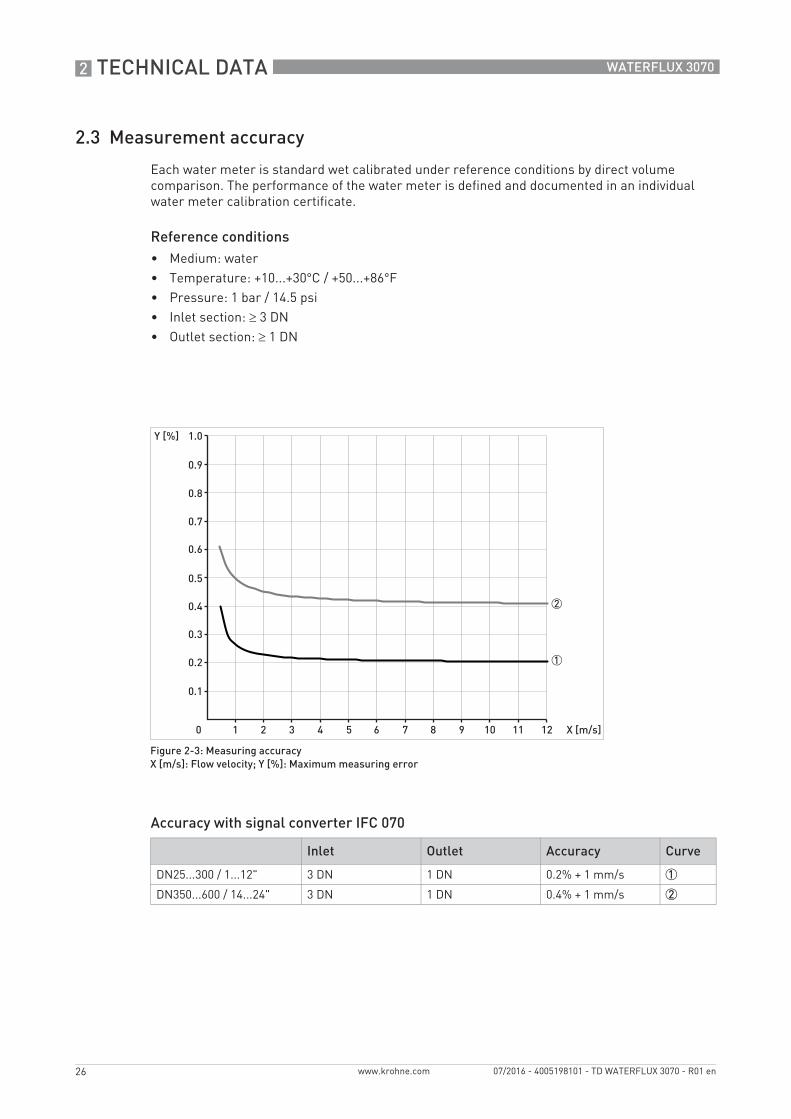
2.3 Measurement accuracy
Each water meter is standard wet calibrated under reference conditions by direct volume comparison. The performance of the water meter is defined and documented in an individual water meter calibration certificate.
Reference conditions• Medium: water• Temperature: +10...+30°C / +50...+86°F• Pressure: 1 bar / 14.5 psi• Inlet section: ≥ 3 DN• Outlet section: ≥ 1 DN
Accuracy with signal converter IFC 070
Figure 2-3: Measuring accuracyX [m/s]: Flow velocity; Y [%]: Maximum measuring error
Inlet Outlet Accuracy Curve
DN25...300 / 1...12" 3 DN 1 DN 0.2% + 1 mm/s 1
DN350...600 / 14...24" 3 DN 1 DN 0.4% + 1 mm/s 2
TECHNICAL DATA 2
27
WATERFLUX 3070
www.krohne.com07/2016 - 4005198101 - TD WATERFLUX 3070 - R01 en
2.3.1 WATERFLUX 3070 without straight inlet and outlet sections
Disturbed flow profiles, such as those that occur behind elbows, tee pieces, reducers or valves installed in front of a water meter, affect the measuring performance. Therefore it is usually recommended to fit a straight inlet length in front of and straight outlet length behind a water meter.
As a result of the unique WATERFLUX flow sensor design, whereby the mean flow velocity and flow profile are optimized within the rectangular and reduced cross section, the additional uncertainty for upstream disturbances are drastically reduced. Therefore the requirements for straight length and in front of and behind a meter are reduced.
The NMi has performed tests with various flow and swirl disturbers according to ISO 4064 and EN 14154. Based on these results the WATERFLUX 3070 has received a
OIML R49 certificate• Diameter range DN25...600• Accuracy class 1 and class 2• Minimum straight inlet and outlet pipe length of 0 DN• Bi-directional flow
EC-type certificate according MID Annex III (MI-001)• Diameter range DN25...600• Minimum straight inlet and outlet pipe length of 0 DN• Bi-directional flow

2 TECHNICAL DATA
28
WATERFLUX 3070
www.krohne.com 07/2016 - 4005198101 - TD WATERFLUX 3070 - R01 en
2.4 Dimensions and weights
Remote flow sensorRemote flow sensorRemote flow sensorRemote flow sensor a = 88 mm / 3.5"
b = 139 mm / 5.5" 1
c = 106 mm / 4.2"
Total height = H + a
Remote Signal converter Remote Signal converter Remote Signal converter Remote Signal converter in polycarbonate housing in polycarbonate housing in polycarbonate housing in polycarbonate housing (IP68)(IP68)(IP68)(IP68)
a = 171 mm / 6.7"
b = 161 mm / 6.3"
b = 177 mm / 7"
Compact version in Compact version in Compact version in Compact version in polycarbonate housing polycarbonate housing polycarbonate housing polycarbonate housing (IP68)(IP68)(IP68)(IP68)
a = 159 mm / 6.3"
b = 161 mm / 6.3"
Total height = H + a
1 The value may vary depending on the used cable glands.
• All data given in the following tables are based on standard versions of the flow sensor only.• Especially for smaller nominal sizes of the flow sensor, the signal converter can be bigger
than the flow sensor.• Note that for other pressure ratings than mentioned, the dimensions may be different.• For full information on signal converter dimensions see relevant documentation.
TECHNICAL DATA 2
29
WATERFLUX 3070
www.krohne.com07/2016 - 4005198101 - TD WATERFLUX 3070 - R01 en
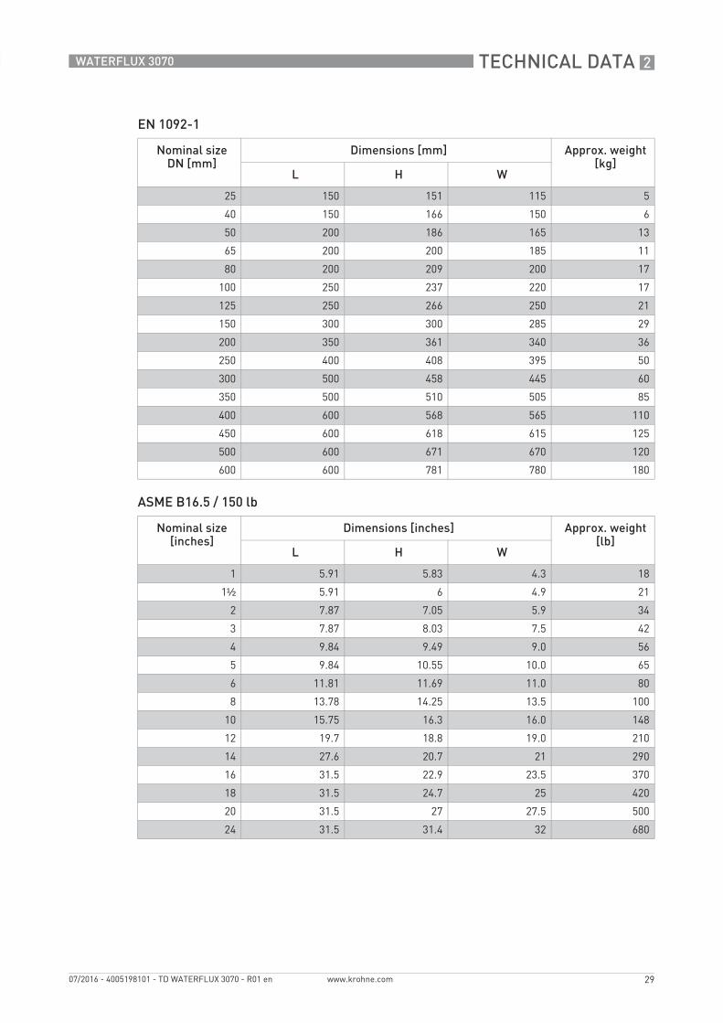
EN 1092-1
ASME B16.5 / 150 lb
Nominal size DN [mm]
Dimensions [mm] Approx. weight [kg]
L H W
25 150 151 115 5
40 150 166 150 6
50 200 186 165 13
65 200 200 185 11
80 200 209 200 17
100 250 237 220 17
125 250 266 250 21
150 300 300 285 29
200 350 361 340 36
250 400 408 395 50
300 500 458 445 60
350 500 510 505 85
400 600 568 565 110
450 600 618 615 125
500 600 671 670 120
600 600 781 780 180
Nominal size [inches]
Dimensions [inches] Approx. weight [lb]
L H W
1 5.91 5.83 4.3 18
1½ 5.91 6 4.9 21
2 7.87 7.05 5.9 34
3 7.87 8.03 7.5 42
4 9.84 9.49 9.0 56
5 9.84 10.55 10.0 65
6 11.81 11.69 11.0 80
8 13.78 14.25 13.5 100
10 15.75 16.3 16.0 148
12 19.7 18.8 19.0 210
14 27.6 20.7 21 290
16 31.5 22.9 23.5 370
18 31.5 24.7 25 420
20 31.5 27 27.5 500
24 31.5 31.4 32 680

2 TECHNICAL DATA
30
WATERFLUX 3070
www.krohne.com 07/2016 - 4005198101 - TD WATERFLUX 3070 - R01 en
2.5 Pressure loss
Figure 2-4: Pressure loss between 1 m/s and 9 m/s for DN25...150
1 DN252 DN403 DN504 DN655 DN806 DN1007 DN1258 DN150
Figure 2-5: Pressure loss between 1 m/s and 9 m/s for DN200...600
1 DN2002 DN2503 DN3004 DN3505 DN4006 DN4507 DN5008 DN600

TECHNICAL DATA 2
31
WATERFLUX 3070
www.krohne.com07/2016 - 4005198101 - TD WATERFLUX 3070 - R01 en
2.6 Battery lifetime
The maximum battery lifetime depends on the choice of battery pack, the diameter and on the measurement interval. Other factors influencing the battery lifetime include the ambient temperature, the pulse output settings, the status output, the pulse width and the Modbus baud rate settings . The graphs show the battery lifetime for the different available battery types and measurement intervals.
Conditions The maximum battery lifetime is based on default menu and Modbus settings, an ambient temperature of 25°C / 77°F and a flow rate at 2 m/s. The effect of the optional pressure and temperature sensor decreases the battery lifetime with 5% (on average).
Maximum lifetime of batteries for: DN25...200
Figure 2-6: XXXX = Measuring interval in seconds, YYYY = typical lifetime in years
Maximum lifetime of batteries for: DN250...600
Figure 2-7: XXXX = Measuring interval in seconds, YYYY = typical lifetime in years
1 Intern Dual D-cell battery2 Extern KROHNE PowerBlock

3 INSTALLATION
32
WATERFLUX 3070
www.krohne.com 07/2016 - 4005198101 - TD WATERFLUX 3070 - R01 en
3.1 General notes on installation
3.2 Intended use
This flowmeter is designed exclusively to measure the flow of drinking water and raw water.
3.3 Pre-installation requirements
Make sure that you have all necessary tools available:• Small screwdriver• Wrench for cable glands (remote version only)• Wrench for wall mounting bracket (remote version only)• Torque wrench for installing flowmeter in pipeline
Inspect the packaging carefully for damages or signs of rough handling. Report damage to the carrier and to the local office of the manufacturer.
Do a check of the packing list to make sure that you have all the elements given in the order.
Look at the device nameplate to ensure that the device is delivered according to your order. Check for the correct supply voltage printed on the nameplate.
Responsibility for the use of the measuring devices with regard to suitability, intended use and corrosion resistance of the used materials against the measured fluid lies solely with the operator.
The manufacturer is not liable for any damage resulting from improper use or use for other than the intended purpose.
If the device is not used according to the operating conditions (refer to chapter Technical data), the intended protection could be affected.
INSTALLATION 3
33
WATERFLUX 3070
www.krohne.com07/2016 - 4005198101 - TD WATERFLUX 3070 - R01 en
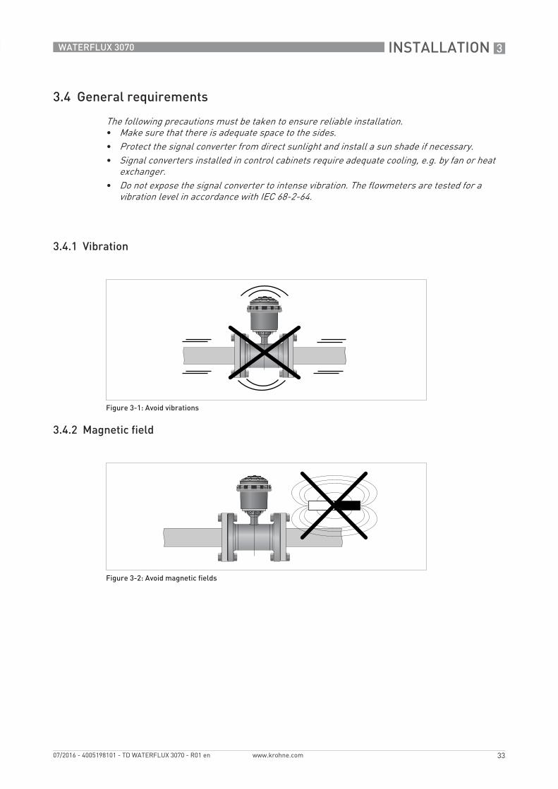
3.4 General requirements
3.4.1 Vibration
3.4.2 Magnetic field
The following precautions must be taken to ensure reliable installation.• Make sure that there is adequate space to the sides.• Protect the signal converter from direct sunlight and install a sun shade if necessary.• Signal converters installed in control cabinets require adequate cooling, e.g. by fan or heat
exchanger.• Do not expose the signal converter to intense vibration. The flowmeters are tested for a
vibration level in accordance with IEC 68-2-64.
Figure 3-1: Avoid vibrations
Figure 3-2: Avoid magnetic fields

3 INSTALLATION
34
WATERFLUX 3070
www.krohne.com 07/2016 - 4005198101 - TD WATERFLUX 3070 - R01 en
3.5 Installation conditions
3.5.1 Inlet and outlet
3.5.2 T-section
3.5.3 Open feed or discharge
To prevent damage to the Rilsan® coating, the WATERFLUX 3000 sensor must be installed carefully. Take precautions during transport and installation to protect the in- and outlet of the sensor.
Figure 3-3: Minimal inlet and outlet
1 Inlet: ≥ 0 DN2 Outlet: ≥ 0 DN
Figure 3-4: Distance behind a T-section
1 ≥ 0 DN
Figure 3-5: Installation in front of an open discharge

INSTALLATION 3
35
WATERFLUX 3070
www.krohne.com07/2016 - 4005198101 - TD WATERFLUX 3070 - R01 en
3.5.4 Bends
3.5.5 Pump
Figure 3-6: Installation in bending pipes
Figure 3-7: Installation in bending pipes
Avoid draining or partial filling of the flow sensor
Figure 3-8: Recommended installation: behind a pump
1 Inlet: ≥ 3 DN

3 INSTALLATION
36
WATERFLUX 3070
www.krohne.com 07/2016 - 4005198101 - TD WATERFLUX 3070 - R01 en
3.5.6 Control valve
3.5.7 Air venting and vacuum forces
Figure 3-9: Recommended installation: in front of a control valve
Figure 3-10: Air venting
1 ≥ 5 m2 Air ventilation point
Figure 3-11: Vacuum
1 ≥ 5 m
INSTALLATION 3
37
WATERFLUX 3070
www.krohne.com07/2016 - 4005198101 - TD WATERFLUX 3070 - R01 en
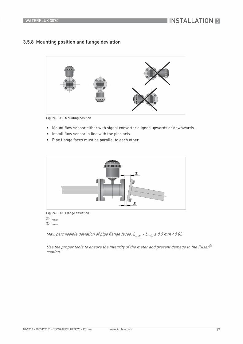
3.5.8 Mounting position and flange deviation
• Mount flow sensor either with signal converter aligned upwards or downwards.• Install flow sensor in line with the pipe axis.• Pipe flange faces must be parallel to each other.
Figure 3-12: Mounting position
Figure 3-13: Flange deviation
1 Lmax2 Lmin
Max. permissible deviation of pipe flange faces: Lmax - Lmin ≤ 0.5 mm / 0.02".
Use the proper tools to ensure the integrity of the meter and prevent damage to the Rilsan® coating.

3 INSTALLATION
38
WATERFLUX 3070
www.krohne.com 07/2016 - 4005198101 - TD WATERFLUX 3070 - R01 en
3.5.9 Installation in a metering pit and subsurface applications
The WATERFLUX 3000 flow sensor is IP68 rated (NEMA 4X/6P) to IEC60529. It is suitable for continuous submersion in flooded measurement chambers and can withstand a 10 meter water column.
The compact and remote version of the IFC 070 signal converter are IP68 rated (NEMA 4/4X/6) and suitable for periodic submersion in flooded measurement chambers.The compact and remote signal converters have a polycarbonate housing and IP68 rated (military) plug and play connectors. Submersion under water is possible down to a depth of 10 meters.In applications with prolonged or continuous submersion, it is advised to use the WATERFLUX 3070 remote version. The remote IFC 070 signal converter and GPRS data logger unit can be installed on the wall of the measuring pit near the lid for visual read out of the display.
Note: figures shows a cable ≤ 25 m / 82 ft
Submersion applications
Figure 3-14: Examples of installation in measuring pit
1 Periodic submersion2 Continuous submersion3 WATERFLUX 3070 Compact4 WATERFLUX 3070 Remote5 Maximum water column 10 meters6 GPRS / data logger unit
Subsurface application
Figure 3-15: Application with buried (subsoil) sensor and a field version converter
1 WATERFLUX 3070 remote version
4
56

INSTALLATION 3
39
WATERFLUX 3070
www.krohne.com07/2016 - 4005198101 - TD WATERFLUX 3070 - R01 en
3.6 Mounting
3.6.1 Torques and pressures
The maximum pressure and torque values for the flowmeter are theoretical and calculated for optimum conditions and use with carbon steel flanges.
Tightening of bolts• Always tighten the bolts uniformly and in diagonally opposite sequence.• Do not exceed the maximum torque value.• Step 1: Apply approx. 50% of max. torque given in table.• Step 2: Apply approx. 80% of max. torque given in table.• Step 3: Apply 100% of max. torque given in table.
Figure 3-16: Tightening of bolts

3 INSTALLATION
40
WATERFLUX 3070
www.krohne.com 07/2016 - 4005198101 - TD WATERFLUX 3070 - R01 en
Nominal sizeDN [mm]
Pressurerating
Bolts Max. torque[Nm] 1
25 PN 16 4 x M 12 12
40 PN 16 4 x M 16 30
50 PN 16 4 x M 16 36
65 PN 16 8 x M 16 50
80 PN 16 8 x M 16 30
100 PN 16 8 x M 16 32
125 PN 16 8 x M 16 40
150 PN 10 8 x M 20 55
150 PN 16 8 x M 20 55
200 PN 10 8 x M 20 85
200 PN 16 12 x M 20 57
250 PN 10 12 x M 20 80
250 PN 16 12 x M 24 100
300 PN 10 12 x M 20 95
300 PN 16 12 x M 24 136
350 PN 10 16 x M 20 96
400 PN 10 16 x M 24 130
450 PN 10 20 x M 24 116
500 PN 10 20 x M 24 134
600 PN 10 20 x M 27 173
1 The torque values also depend on variables (temperature, bolt material, gasket material, lubricants, etc.) outside the control of the manufacturer. Therefore these values should be regarded as indicative only.

INSTALLATION 3
41
WATERFLUX 3070
www.krohne.com07/2016 - 4005198101 - TD WATERFLUX 3070 - R01 en
Nominal size[inch]
Flange class[lb]
Bolts Max. torque[lbs.ft] 1
1 150 4 x 1/2" 4
1½ 150 4 x 1/2" 11
2 150 4 x 5/8" 18
2.5 150 8 x 5/8" 27
3 150 4 x 5/8" 33
4 150 8 x 5/8" 22
5 150 8 x 3/4" 33
6 150 8 x 3/4" 48
8 150 8 x 3/4" 66
10 150 12 x 7/8" 74
12 150 12 x 7/8" 106
14 150 2 12 x 1" 87
16 150 2 16 x 1" 84
18 150 2 16 x 1 1/8" 131
20 150 2 20 x 1 1/8" 118
24 150 2 20 x 1 1/4" 166
1 The torque values also depend on variables (temperature, bolt material, gasket material, lubricants, etc.) outside the control of the manufacturer. Therefore these values should be regarded as indicative only.
2 No full rating (max. 150 psi / 10 bar).

3 INSTALLATION
42
WATERFLUX 3070
www.krohne.com 07/2016 - 4005198101 - TD WATERFLUX 3070 - R01 en
3.7 Mounting of the signal converter
3.7.1 Remote converter housing
Assembly materials and tools are not part of the delivery. Use the assembly materials and tools in compliance with the applicable occupational health and safety directives.
Figure 3-17: Mounting of the wall holder
1 Mark the fixation points.2 Drill the holes and mount the holder with the right screws (eg. M6 x 50 with washer) and plugs.
Do not exceed a tightening torque of 2 Nm when fastening the screws. This can damage the wall holder3 Slide the IP68 remote version housing into the holder as shown.
Make sure that the positioning cam * is placed in the guiding provided for that purpose (power and data connectors positioned on the backside).
4 Turn the housing 180° counter clockwise (until the power and data connectors are on the front side).Make sure that the holder snaps into the lock of the wall holder.
5 Bottom view of the IP68 remote version in to the wall holder.

INSTALLATION 3
43
WATERFLUX 3070
www.krohne.com07/2016 - 4005198101 - TD WATERFLUX 3070 - R01 en
3.7.2 Closing of the converter housing
• Before closing the case of the converter, ensure that all surfaces in contact with the seals are clean.
• Position the upper part of the case and tighten the lock ring, up until the positions of points 1 and 2 are inline (do not tighten the ring any further).
• Use the special wrench to tighten the ring as advised above.• If applicable, place a new utility seal (see section Utility Seal)
Figure 3-18: Closing of the converter housing
4 ELECTRICAL CONNECTIONS
44
WATERFLUX 3070
www.krohne.com 07/2016 - 4005198101 - TD WATERFLUX 3070 - R01 en
4.1 Safety instructions
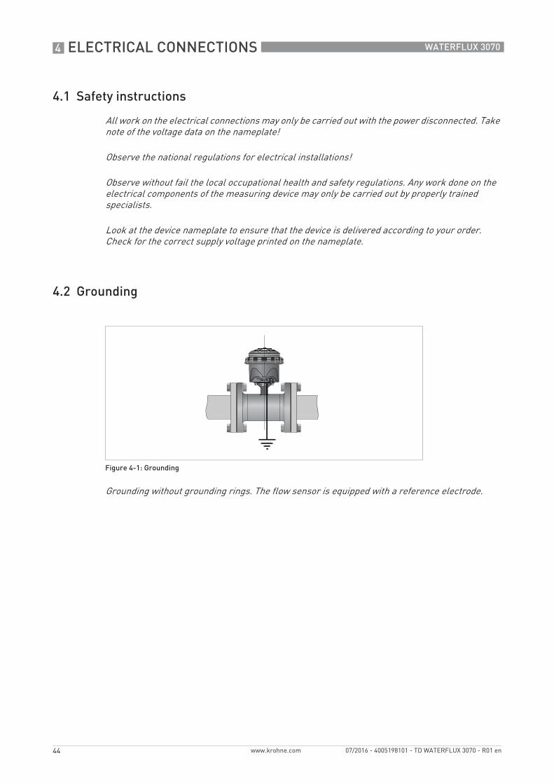
4.2 Grounding
All work on the electrical connections may only be carried out with the power disconnected. Take note of the voltage data on the nameplate!
Observe the national regulations for electrical installations!
Observe without fail the local occupational health and safety regulations. Any work done on the electrical components of the measuring device may only be carried out by properly trained specialists.
Look at the device nameplate to ensure that the device is delivered according to your order. Check for the correct supply voltage printed on the nameplate.
Figure 4-1: Grounding
Grounding without grounding rings. The flow sensor is equipped with a reference electrode.

ELECTRICAL CONNECTIONS 4
45
WATERFLUX 3070
www.krohne.com07/2016 - 4005198101 - TD WATERFLUX 3070 - R01 en
4.3 Cable overview
The following overview describes the different cables available for the compact and remote version
The sensor cable for the IP68 remote (field) version has an 8 pins male connector. The I/O cable (pulse /modbus) is available in a KROHNE FlexPower version and has an additional power cable connection.
Overview I/O cables, with or without a power cable, with female connector:
IP 68 Cable versions
Electrical values• Pulse outputPulse outputPulse outputPulse output
2x Pulse output passive - ( maximum 3 outputs possible, see status output): 2x Pulse output passive - ( maximum 3 outputs possible, see status output): 2x Pulse output passive - ( maximum 3 outputs possible, see status output): 2x Pulse output passive - ( maximum 3 outputs possible, see status output): f ≤ 100 Hz; I ≤ 10 mA; U: 2.7...24 VDC (P ≤ 100 mW)
• Status outputStatus outputStatus outputStatus output2x Status output passive - ( 1 status output can be used as a third pulse output):2x Status output passive - ( 1 status output can be used as a third pulse output):2x Status output passive - ( 1 status output can be used as a third pulse output):2x Status output passive - ( 1 status output can be used as a third pulse output):I ≤ 10 mA; U: 2.7...24 VDC (P ≤ 100 mW)
• CommunicationCommunicationCommunicationCommunicationModbus RTU output - (detailed information available in Supplementary Manual)
• Optional: Optional: Optional: Optional: KGA external data logger / GSM module - (see the KGA 42 Supplementary Manual)
I/O version KROHNE FlexPower cable PIN
Modbus cable N 4
Pulse cable N 8
KGA 42 N 8
Modbus cable Y 10
Pulse cable Y 8
KGA 42 Y 8

4 ELECTRICAL CONNECTIONS
46
WATERFLUX 3070
www.krohne.com 07/2016 - 4005198101 - TD WATERFLUX 3070 - R01 en
4.4 Connection of the sensor cable
The compact version of the WATERFLUX 3070 is already internally connected to the sensor and has different options to connect pulse, modbus and/or external supply cables. See the following sections for the different options and available cables.For the WATERFLUX 3070 (F) remote version, a standard cable is delivered with the device. On the sensor side the cable is standard potted at the factory. The sensor cable has a IP68 rated RVS snap-on connection to connect the sensor with the IP68 field converter with the following color coded leads leads:
Standard sensor cable
Sensor cable with integrated P&T option
Wire color Terminal Function
Brown 1 Reference electrode
White 2 Standard electrode signal
Violet 3 Standard electrode signal
Blue 7 Field current
Green 8 Field current
Yellow 9 No function
Drain wires Screws Shielding
The standard WSC2 sensor cable (double shielded), includes both electrode and field current leads and has a maximum length of 25 m / 82 ft. (other lengths on request).
Wire color Contact on connector
Terminal Function
Brown H 1 Reference electrode / P&T sensor
White D 4 P&T sensor
Grey F 5 P&T sensor
Pink B 6 P&T sensor
Blue A 7 Field current
Green G 8 Field current
White/White C 2 Standard electrode signal
White/Red E 3 Standard electrode signal
Drain wires Housing Screws Shielding
To ensure smooth functioning, always use the signal cables included in the delivery

ELECTRICAL CONNECTIONS 4
47
WATERFLUX 3070
www.krohne.com07/2016 - 4005198101 - TD WATERFLUX 3070 - R01 en
4.5 Connection of the signal cable
4.5.1 IP68 housing (compact version)
If an output is activated, the output cable with the IP68 rated connector has the following color coded leads:
Pulse output cable
Modbus cable
Note: See for the combined power and modbus / pulse cable options, next chapter
Figure 4-2: Output cable at IP68 compact version
1 Color coded leads of the output cable
Wire color Contact on connector
Function
Yellow A Status output 1 or threshold for P or T or pulse output C
White G Status output 2 or threshold for P or T
Blue H Ground
Brown B Pulse output A
Green F Pulse output B
Pink C External battery +
Grey E External battery -
Note; with or without shielding
Wire color Contact on connector
Function
Yellow 1 Down link wire B←
Grey 1 Up link wire B→
Pink 2 Up link wire A→
Green 2 Down link wire A←
White 3 Ground
Brown - -
Shield Earth

4 ELECTRICAL CONNECTIONS
48
WATERFLUX 3070
www.krohne.com 07/2016 - 4005198101 - TD WATERFLUX 3070 - R01 en
4.5.2 IP68 housing (remote version)
Sensor cable: refer to Connection of the sensor cable on page 46 for the available connection options
For connection of I/O ( modbus, pulse output signals) with or without additional power supply cable connection, several cable connection options are available. The cables have the following color code leads.
Output pulse cable
Modbus cable
Figure 4-3: Different output cable, IP68 remote version
1 Color coded leads of sensor cable2 Y - cable with additional power cable3 I/O cable (pulse, modbus)4 I/O connection 5 RVS sensor cable connection
Wire color Contact on connector
Function
Yellow A Status output 1 or threshold for P or T or pulse output C
White G Status output 2 or threshold for P or T
Blue H Ground
Brown B Pulse output A
Green F Pulse output B
Pink C External battery +
Grey E External battery -
Wire color Contact on connector
Function
Yellow 1 Down link wire B←
Grey 1 Up link wire B→
Pink 2 Up link wire A→
Green 2 Down link wire A←
White 3 Ground
Brown - -
Shield Earth

ELECTRICAL CONNECTIONS 4
49
WATERFLUX 3070
www.krohne.com07/2016 - 4005198101 - TD WATERFLUX 3070 - R01 en
Combined power and pulse output cable ( Y-cable)
Combined power and Modbus cable ( Y-cable)
This cable has two pair of wires, one for uplink and one for downlink. Both are connected within the connector. When disconnecting the cable on the sensor side, the two paired wires will stay connected so there is disconnection of the RS-485.
Because of this connection (switching link wire), it makes no difference where the up- and downlink are connected.
Wire color Contact on connector
Function
Yellow A Status output 1 or threshold for P or T or pulse output C
White G Status output 2 or threshold for P or T
Grey H Ground
Brown B Pulse output A
Green F Pulse output B
Brown C External power +3.6V
White E External power (Ground)
Shield D Shielding
Wire color Contact on connector
Function
Shield C Shielding
Brown B -
White A Ground
Green E Down link wire A←
Yellow K Down link wire B←
Pink H Up link wire A→
Grey J Up link wire B→
Brown F External power +3.6V
White G External power (Ground)
Shield D Shielding
For proper use and installation, it is recommended to follow the advised color coded wire connections in the table above.A 120Ω line terminator is required when the WATERFLUX 3070 converter is the last device in line and/or is part of the bus connection.
Specific information is described in the supplementary Modbus manual, available on the manufacturer website.

5 NOTES
50
WATERFLUX 3070
www.krohne.com 07/2016 - 4005198101 - TD WATERFLUX 3070 - R01 en

KROHNE – Process instrumentation and measurement solutions
• Flow
• Level
• Temperature
• Pressure
• Process Analysis
• Services
Head Office KROHNE Messtechnik GmbHLudwig-Krohne-Str. 547058 Duisburg (Germany)Tel.: +49 203 301 0Fax: +49 203 301 [email protected]
© K
RO
HN
E 07
/201
6 -
4005
1981
01 -
TD
WA
TER
FLU
X 30
70 -
R01
en
- Su
bjec
t to
chan
ge w
ithou
t not
ice.
The current list of all KROHNE contacts and addresses can be found at:www.krohne.com
KK
K