TCSESM Installation Manual V7
40
www.schneider-electric.com 31007118.07 ConneXium TCSESM Managed Switch Installation Manual TCSESM043F23F0 V.24 IP-ADDRESS ConneXium Switch WARNING WARNING UNINTENDED OPERATION Do not change cable positions if DHCP Option 82 is enabled. Check user manual before servicing. +24V(P1) +24V(P2) 1 2 3 4 LNK ACT LNK ACT LNK ACT LNK ACT Fault 0V 0V RM P Fault RM Stand by USB Stand by ON MAC-Address V.24 IP-ADDRESS 3 4 5 6 7 8 ConneXium Switch WARNING WARNING UNINTENDED OPERATION Do not change cable positions if DHCP Option 82 is enabled. Check user manual before servicing. RM P RM Fault Stand by USB Stand by ON Fault 0V 0V +24V(P1) +24V(P2) 2 LNK ACT 1 LNK ACT MAC-Address TCSESM083F2CU0/CS0/CX0 2 LNK ACT 1 LNK ACT ConneXium Switch RM P RM Fault V.24 Stand by USB Stand by ON IP-ADDRESS Fault 0V 0V +24V(P1) +24V(P2) 3 4 5 6 7 8 9 10 11 12 13 14 15 16 MAC-Address WARNING WARNING UNINTENDED OPERATION Do not change cable positions if DHCP Option 82 is enabled. Check user manual before servicing. TCSESM163F2CU0/CS0 11 12 13 14 15 16 17 18 19 20 21 22 23 24 3 4 5 6 7 8 9 10 RM P RM Fault Stand by USB Stand by ON V.24 ConneXium Switch 2 LNK ACT 1 LNK ACT Fault 0V 0V +24V(P1) +24V(P2) MAC-Address IP-ADDRESS WARNING WARNING UNINTENDED OPERATION Do not change cable positions if DHCP Option 82 is enabled. Check user manual before servicing. TCSESM243F2CU0
-
Upload
stanca-nicolae -
Category
Documents
-
view
114 -
download
11
description
CARTE TEHNICA tcesem
Transcript of TCSESM Installation Manual V7
3100
7118
.07
ConneXium
TCSESM Managed SwitchInstallation Manual
TCSESM043F23F0
V.24
IP-A
DD
RE
SS
ConneXium Switch
WARNING
WARNING
UN
INT
EN
DE
D O
PE
RA
TIO
N D
o no
t cha
nge
cabl
e po
sitio
ns if
DH
CP
Opt
ion
82 is
ena
bled
. C
heck
use
r man
ual b
efor
e se
rvic
ing.
+24V(P1) +24V(P2)
1
2
3
4
LNK
ACTLNK
ACTLNK
ACTLNK
ACT
Fault0V 0V
RMP Fault
RMStand by
USB
Stand byON
MA
C-A
ddre
ss
V.24
IP-A
DD
RE
SS
3 4
5 6
7 8
ConneXium Switch
WARNING
WARNING
UN
INT
EN
DE
D O
PE
RA
TIO
N D
o no
t cha
nge
cabl
e po
sitio
ns if
DH
CP
Opt
ion
82 is
ena
bled
. C
heck
use
r man
ual b
efor
e se
rvic
ing.
RMP
RM
Fault
Stand by
USB
Stand byON
Fault0V 0V+24V(P1) +24V(P2)
2
LNK ACT
1
LNK ACT
MA
C-A
ddre
ss
TCSESM083F2CU0/CS0/CX0
2
LNK ACT
1
LNK ACT
ConneXium Switch
RMP
RM
Fault
V.24
Stand by
USB
Stand byON
IP-A
DD
RE
SS
Fault0V 0V+24V(P1) +24V(P2)
3 4
5 6
7 8
9 10
11 12
13 14
15 16
MA
C-A
ddre
ss
WARNING
WARNING
UN
INT
EN
DE
D O
PE
RA
TIO
N D
o no
t cha
nge
cabl
e po
sitio
ns if
DH
CP
Opt
ion
82 is
ena
bled
. C
heck
use
r man
ual b
efor
e se
rvic
ing.
TCSESM163F2CU0/CS0
11 12
13 14
15 16
17 18
19 20
21 22
23 24
3 4
5 6
7 8
9 10
RMP
RM
Fault
Stand by
USB
Stand byON
V.24
ConneXium Switch
2
LNK ACT
1
LNK ACT
Fault0V 0V+24V(P1) +24V(P2)
MA
C-A
ddre
ss
IP-A
DD
RE
SS
WARNING
WARNING
UN
INT
EN
DE
D O
PE
RA
TIO
N D
o no
t cha
nge
cabl
e po
sitio
ns if
DH
CP
Opt
ion
82 is
ena
bled
. C
heck
use
r man
ual b
efor
e se
rvic
ing.
TCSESM243F2CU0
www.schneider-electric.com

Contents
About this Manual 3
Key 5
Safety instructions 5
1 Device description 12
1.1 General device description 12
1.2 Device versions 141.2.1 Device versions 141.2.2 Examples of switch versions 15
2 Assembly and start-up 19
2.1 Safety instructions 19
2.2 Installing the device 202.2.1 Overview of installation 202.2.2 Unpacking and checking 202.2.3 Installing the SFP modules (optional) 212.2.4 Insert data in label area 212.2.5 Adjust DIP switch settings 222.2.6 Supply voltage and signal contact 222.2.7 Installing the device on the DIN rail, grounding 242.2.8 Dimension drawings 252.2.9 Installing the terminal block, start-up procedure 262.2.10 Connecting the data lines 26
2.3 Display elements 29
2.4 Basic set-up 30
2.5 Maintenance 33
2.6 Disassembly 33
3 Technical data 34
2 31007118 - 06/2012

About this Manual
Validity NoteThe data and illustrations found in this book are not binding. We reserve the right to modify our products in line with our policy of continuous product development. The information in this document is subject to change without notice and should not be construed as a commitment by Schneider Electric.
Product Related InformationSchneider Electric assumes no responsibility for any errors that may appear in this document. If you have any suggestions for improvements or amendments or have found errors in this publication, please notify us.
No part of this document may be reproduced in any form or by any means, electronic or mechanical, including photocopying, without express written permission of Schneider Electric.
All pertinent state, regional, and local safety regulations must be observed when installing and using this product. For reasons of safety and to ensure compliance with documented system data, only the manufacturer should perform repairs to components.
When devices are used for applications with technical safety requirements, please follow the relevant instructions.
Failure to use Schneider Electric software or approved software with our hardware products may result in improper operating results.
Failure to observe this product related warning can result in injury or equipment damage.
User CommentsWe welcome your comments about this document. You can reach us by e-mail at [email protected]
31007118 - 06/2012 3
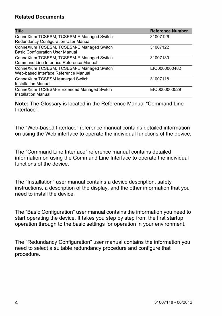
Related Documents
Note: The Glossary is located in the Reference Manual “Command Line Interface”.
The “Web-based Interface” reference manual contains detailed information on using the Web interface to operate the individual functions of the device.
The “Command Line Interface” reference manual contains detailed information on using the Command Line Interface to operate the individual functions of the device.
The “Installation” user manual contains a device description, safety instructions, a description of the display, and the other information that you need to install the device.
The “Basic Configuration” user manual contains the information you need to start operating the device. It takes you step by step from the first startup operation through to the basic settings for operation in your environment.
The “Redundancy Configuration” user manual contains the information you need to select a suitable redundancy procedure and configure that procedure.
Title Reference NumberConneXium TCSESM, TCSESM-E Managed Switch Redundancy Configuration User Manual
31007126
ConneXium TCSESM, TCSESM-E Managed Switch Basic Configuration User Manual
31007122
ConneXium TCSESM, TCSESM-E Managed Switch Command Line Interface Reference Manual
31007130
ConneXium TCSESM, TCSESM-E Managed Switch Web-based Interface Reference Manual
EIO0000000482
ConneXium TCSESM Managed Switch Installation Manual
31007118
ConneXium TCSESM-E Extended Managed Switch Installation Manual
EIO0000000529
4 31007118 - 06/2012
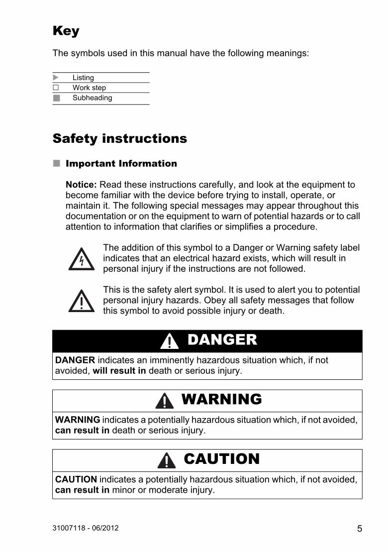
KeyThe symbols used in this manual have the following meanings:
Safety instructions
Important Information
Notice: Read these instructions carefully, and look at the equipment to become familiar with the device before trying to install, operate, or maintain it. The following special messages may appear throughout this documentation or on the equipment to warn of potential hazards or to call attention to information that clarifies or simplifies a procedure.
The addition of this symbol to a Danger or Warning safety label indicates that an electrical hazard exists, which will result in personal injury if the instructions are not followed.
This is the safety alert symbol. It is used to alert you to potential personal injury hazards. Obey all safety messages that follow this symbol to avoid possible injury or death.
Listing Work step
Subheading
DANGERDANGER indicates an imminently hazardous situation which, if not avoided, will result in death or serious injury.
WARNINGWARNING indicates a potentially hazardous situation which, if not avoided, can result in death or serious injury.
CAUTIONCAUTION indicates a potentially hazardous situation which, if not avoided, can result in minor or moderate injury.
31007118 - 06/2012 5
PLEASE NOTE: Electrical equipment should be installed, operated, serviced, and maintained only by qualified personnel. No responsibility is assumed by Schneider Electric for any consequences arising out of the use of this material. © 2012 Schneider Electric. All Rights Reserved.
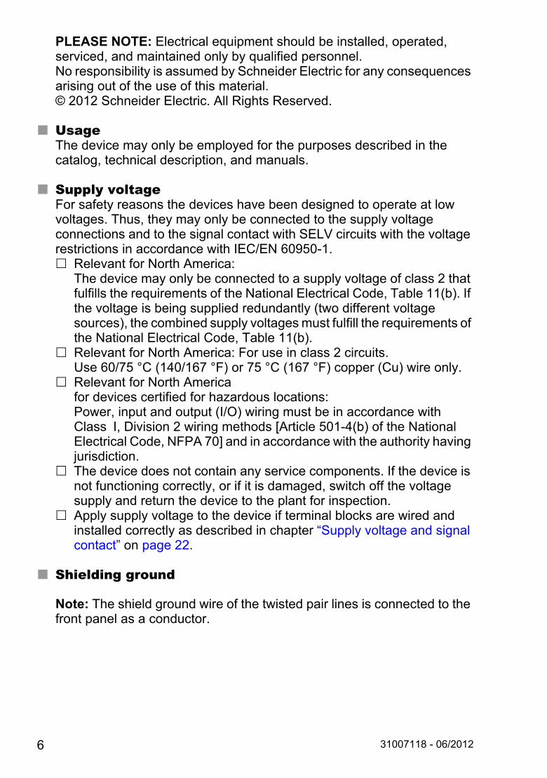
UsageThe device may only be employed for the purposes described in the catalog, technical description, and manuals.
Supply voltageFor safety reasons the devices have been designed to operate at low voltages. Thus, they may only be connected to the supply voltage connections and to the signal contact with SELV circuits with the voltage restrictions in accordance with IEC/EN 60950-1. Relevant for North America:
The device may only be connected to a supply voltage of class 2 that fulfills the requirements of the National Electrical Code, Table 11(b). If the voltage is being supplied redundantly (two different voltage sources), the combined supply voltages must fulfill the requirements of the National Electrical Code, Table 11(b).
Relevant for North America: For use in class 2 circuits.Use 60/75 °C (140/167 °F) or 75 °C (167 °F) copper (Cu) wire only.
Relevant for North Americafor devices certified for hazardous locations:Power, input and output (I/O) wiring must be in accordance with Class I, Division 2 wiring methods [Article 501-4(b) of the National Electrical Code, NFPA 70] and in accordance with the authority having jurisdiction.
The device does not contain any service components. If the device is not functioning correctly, or if it is damaged, switch off the voltage supply and return the device to the plant for inspection.
Apply supply voltage to the device if terminal blocks are wired and installed correctly as described in chapter “Supply voltage and signal contact” on page 22.
Shielding ground
Note: The shield ground wire of the twisted pair lines is connected to the front panel as a conductor.
6 31007118 - 06/2012
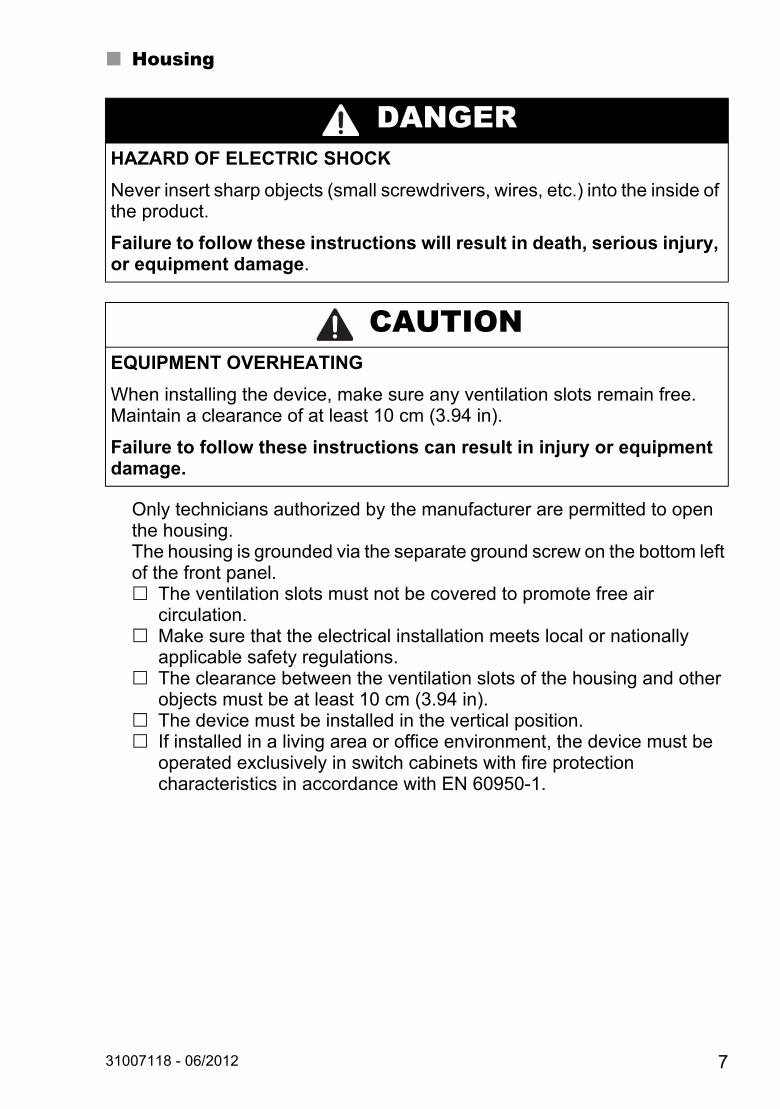
Housing
Only technicians authorized by the manufacturer are permitted to open the housing.The housing is grounded via the separate ground screw on the bottom left of the front panel. The ventilation slots must not be covered to promote free air
circulation. Make sure that the electrical installation meets local or nationally
applicable safety regulations. The clearance between the ventilation slots of the housing and other
objects must be at least 10 cm (3.94 in). The device must be installed in the vertical position. If installed in a living area or office environment, the device must be
operated exclusively in switch cabinets with fire protection characteristics in accordance with EN 60950-1.
DANGERHAZARD OF ELECTRIC SHOCK
Never insert sharp objects (small screwdrivers, wires, etc.) into the inside of the product.
Failure to follow these instructions will result in death, serious injury, or equipment damage.
CAUTIONEQUIPMENT OVERHEATING
When installing the device, make sure any ventilation slots remain free. Maintain a clearance of at least 10 cm (3.94 in).
Failure to follow these instructions can result in injury or equipment damage.
31007118 - 06/2012 7

EnvironmentThe device may only be operated at the specified surrounding air temperature (temperature of the surrounding air at a distance of up to 5 cm (1.97 in) from the device) and relative air humidity specified in the technical data. Install the device in a location where the climatic threshold values
specified in the technical data will be observed. Use the device only in an environment within the pollution degree
specified in the technical data.
General safety instructionsElectricity is used to operate this equipment. Comply with every detail of the safety requirements specified in the operating instructions regarding the voltages to apply.See “Supply voltage” on page 6. Only qualified personnel should work on this device or in its vicinity.
These personnel must be thoroughly familiar with all the hazard messages and maintenance procedures in accordance with this operating manual.
The proper and safe operation of this device depends on proper handling during transport, proper storage and assembly, and conscientious operation and maintenance procedures.
Never start operation with damaged components. Any work that may be required on the electrical installation may only
be carried out by personnel trained for this purpose.
Note: LED or LASER components in compliance with IEC 60825-1 (2007):CLASS 1 LASER PRODUCTCLASS 1 LED PRODUCT
National and international safety regulations Make sure that the electrical installation meets local or nationally
applicable safety regulations.
CE markingThe devices comply with the regulations contained in the following European directive(s):
2011/65/EU (RoHS)Directive of the European Parliament and of the Council on the restriction of the use of certain hazardous substances in electrical and electronic equipment.
8 31007118 - 06/2012
2004/108/ECDirective of the European Parliament and the council for standardizing the regulations of member states with regard to electromagnetic compatibility.
In accordance with the above-named EU directive(s), the EU conformity declaration will be at the disposal of the relevant authorities at the following address:
Schneider Electric35 rue Joseph MonierCS3032392506 Rueil-Malmaison-France
The product can be used in the industrial sector. Interference immunity: EN 61000-6-2:2005 Emitted interference: EN 55022:2010
FCC noteThis device complies with part 15 of the FCC rules. Operation is subject to the following two conditions : (1) This device may not cause harmful interference; (2) this device must accept any interference received, including interference that may cause undesired operation.Appropriate testing has established that this device fulfills the requirements of a class A digital device in line with part 15 of the FCC regulations.These requirements are designed to provide sufficient protection against interference when the device is being used in a business environment. The device creates and uses high frequencies and can also radiate high frequencies, and if it is not installed and used in accordance with this operating manual, it can cause radio transmission interference. The use of this device in a living area can also cause interference, and in this case the user is obliged to cover the costs of removing the interference.
Instructions for Use in Hazardous LocationsSUITABLE FOR USE IN CLASS I, DIVISION 2, GROUPS A, B, C AND D HAZARDOUS LOCATIONS, OR NONHAZARDOUS LOCATIONS ONLY.Peripheral equipment must be suitable for the location it is used in.Use 60/75 °C (140/167 °F) or 75 °C (167 °F) copper (Cu) wire only.
31007118 - 06/2012 9
WARNINGEXPLOSION HAZARDSubstitution of any components may impair suitability for CLASS I, DIVISION 2.
Failure to follow these instructions can result in death, serious injury, or equipment damage.
WARNINGEXPLOSION HAZARDDo not disconnect equipment unless power has been switched off or the area is known to be non-hazardous.
Failure to follow these instructions can result in death, serious injury, or equipment damage.
WARNINGEXPLOSION HAZARDDo not use USB connector, or connect or disconnect devices from it unless the area is known to be non-hazardous.
Failure to follow these instructions can result in death, serious injury, or equipment damage.
10 31007118 - 06/2012
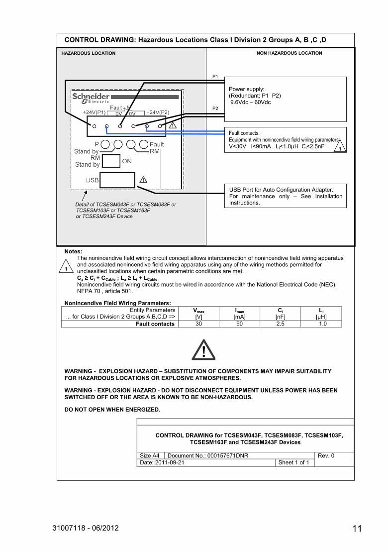
�CONTROL DRAWING: Hazardous Locations Class I Division 2 Groups A, B ,C ,D
���������������������������Notes:
������������������ ��������������������� ����������������������������������� �������������������������������������������� ���������������������������������������������������������������� �������� ������������������������������������������������Ca � Ci + CCable ; La � Li + LCable
�������������� ������������������������������������������������������ �� ����� �������������� !"�#$������� ��%$&���
Nonincendive Field Wiring Parameters:
�������!���������������������� ����'�(��������)�*������"�+���(�,-�
Vmax�./0�
Imax�.�"0�
Ci�.� 0�
Li�.120�
�������������������������������������������� Fault contacts 3$� 4$� )�%� &�$�
WARNING - EXPLOSION HAZARD – SUBSTITUTION OF COMPONENTS MAY IMPAIR SUITABILITY
FOR HAZARDOUS LOCATIONS OR EXPLOSIVE ATMOSPHERES.
WARNING - EXPLOSION HAZARD - DO NOT DISCONNECT EQUIPMENT UNLESS POWER HAS BEEN
SWITCHED OFF OR THE AREA IS KNOWN TO BE NON-HAZARDOUS.
DO NOT OPEN WHEN ENERGIZED. �
�5�
CONTROL DRAWING for TCSESM043F, TCSESM083F, TCSESM103F,
TCSESM163F and TCSESM243F Devices
�6�7��"8� (����������5�$$$&%#9#&(�:� :����$�(���5�)$&&;$4;)&� 6�����&����&� �
NON HAZARDOUS LOCATION
�
<6+�!��������"������������������"������� ���������������� ��=�6���
!&��!)�
�
HAZARDOUS LOCATION
Detail of TCSESM043F or TCSESM083F or TCSESM103F or TCSESM163F
or TCSESM243F Device
1
��������������� ���������������������������������������������/>3$/���'>4$�"���?�>&�$12����>)�%� � 1
!&������!)�
<6+�!��������"������������������"������� ��� ����������� �� �� =� 6��� '���� ������'������������
�!��������� �5��:������5�!&��!)���4�9/�=�9$/������������������
31007118 - 06/2012 11
1 Device description
1.1 General device descriptionA TCSESM switch is a compact, heavy-duty device suitable for industrial applications which can be installed on a standard DIN Rail. The switches are available in 4, 8, 10, 16 and 24 ports combinations. Two of these ports, uplinks, usually used to implement the ring architectures, could be available in Copper or Fiber (multimode, singlemode) and in 10/100 Mbps or Gigabit speeds.
The 10-60VDC/18-30VAC operating voltage is supplied via a plug-in terminal block with two connections to wire primary and redundant voltage if necessary. An alarm relay allows reporting diagnostic information (P/S, Link signal, Redundancy health) to Control systems. Integrated LEDs allow fast on-site installation and troubleshooting.
Depending on the device variant, you can choose various media to connect terminal devices and other infrastructure components: twisted pair cable multimode F/O singlemode F/O
The twisted pair ports support: Autocrossing Autonegotiation Autopolarity
There are convenient options for managing the device. Administer your devices via: a Web browser Telnet a V.24 interface (locally on the device)
Product configuration data can be provided by: diagnosis displays displaying the operating parameters a label area for the IP address
The devices provide you with a large range of functions: Redundancy functions Rapid Spanning Tree Protocol (RSTP) HIPER-Ring Redundant coupling Redundant power supply Media Redundancy Protocol (MRP)
12 31007118 - 06/2012
Security Protection from unauthorized access Blocking of unauthorized messages (MAC or IP based)
Synchronized system time in the network Network load control Operation diagnosis Diagnostics (hardware self-testing) Reset Priority VLAN Topology Discovery Web-based Interface Command Line Interface CLI SNMP Real Time Clock
31007118 - 06/2012 13

1.2 Device versions
1.2.1 Device versions
Part Number Part Number Description4 Port Version TCSESM043F23F0 4 10/100 TX Managed
TCSESM043F1CU0 3 10/100 TX 1 100 FX-MM ManagedTCSESM043F2CU0 2 10/100 TX 2 100 FX-MM ManagedTCSESM043F1CS0 3 10/100 TX 1 100 FX-SM ManagedTCSESM043F2CS0 2 10/100 TX 2 100 FX-SM Managed
8 Port Version TCSESM083F23F0 8 10/100 TX ManagedTCSESM083F1CU0 7 10/100 TX 1 100 FX-MM ManagedTCSESM083F2CU0 6 10/100 TX 2 100 FX-MM ManagedTCSESM083F1CS0 7 10/100 TX 1 100 FX-SM ManagedTCSESM083F2CS0 6 10/100 TX 2 100 FX-SM Managed
16 Port Version TCSESM163F23F0 16 10/100 TX ManagedTCSESM163F2CU0 14 10/100 TX 2 100 FX-MM ManagedTCSESM163F2CS0 14 10/100 TX 2 100 FX-SM Managed
24 Port Version TCSESM243F2CU0 22 10/100 TX 2 100 FX-MM ManagedGigabit - 10 Port Version
TCSESM103F23G0 8 10/100 TX 2 10/100/1000 TX ManagedTCSESM103F2LG0 8 10/100 TX, 2 1000 SFP (fiber) Managed
Note: This product ships with open sockets (SFP) on the fiber ports. In order to use these ports, order 1 or 2 fiber modules in any combination (see below).
Fiber Media Modules for Gigabit
TCSEAAF1LFU00 fiber module SFP-SX/LCTCSEAAF1LFS00 fiber module SFP-LX/LCTCSEAAF1LFH00 fiber module SFP-LH/LC
Accessories TCSEAM0100 Adapter Memory Back-up Adapter490NTRJ11 Cable Terminal 490NTRJ11 cable
14 31007118 - 06/2012

1.2.2 Examples of switch versions
Figure 1: The figure shows the 4-port versions of the TCSESM.1 – plug-in terminal block, 6-pin2 – LED display elements3 – 2-pin DIP switch4 – USB interface5 – V.24 connection for external management6 – MAC address field7 – ports in compliance with 10/100BASE-T(X) (RJ45 connections)8 – protective ground (PE)9 – IP address field10 – port 1 + port 2, free choice of connections: Twisted Pair T(X), RJ45, 10/100 Mbit/s Multimode FX, DSC, 100 Mbit/s Singlemode FX, DSC, 100 Mbit/s
TCSESM043F23F0
V.24
IP-A
DD
RE
SS
ConneXium Switch
WARNING
WARNING
UN
INT
EN
DE
D O
PE
RA
TIO
N D
o no
t cha
nge
cabl
e po
sitio
ns if
DH
CP
Opt
ion
82 is
ena
bled
. C
heck
use
r man
ual b
efor
e se
rvic
ing.
+24V(P1) +24V(P2)
1
2
3
4
LNK
ACTLNK
ACTLNK
ACTLNK
ACT
Fault0V 0V
RMP Fault
RMStand by
USB
Stand byON
MA
C-A
ddre
ss
TCSESM043F2CU0/CS0
1
2
LNK
ACT
3
4
LNK
ACT
RMP
RM
Fault
V.24
Stand by
USB
Stand byON
IP-A
DD
RE
SS
LNK
ACTLNK
ACT2
1
ConneXium Switch
Fault0V 0V+24V(P1) +24V(P2)
WARNING
WARNING
UN
INT
EN
DE
D O
PE
RA
TIO
N D
o no
t cha
nge
cabl
e po
sitio
ns if
DH
CP
Opt
ion
82 is
ena
bled
. C
heck
use
r man
ual b
efor
e se
rvic
ing.
MA
C-A
ddre
ss
TCSESM043F1CU0/CS0
RM
V.24
IP-A
DD
RE
SS
P Fault
ConneXium Switch
RMStand by
USB
Stand byON
1
WARNING
WARNING
UN
INT
EN
DE
D O
PE
RA
TIO
N D
o no
t cha
nge
cabl
e po
sitio
ns if
DH
CP
Opt
ion
82 is
ena
bled
. C
heck
use
r man
ual b
efor
e se
rvic
ing.
1
2
3
4
LNK
ACTLNK
ACTLNK
ACTLNK
ACT
Fault0V 0V+24V(P1) +24V(P2)
MA
C-A
ddre
ss
1
2
3
4
6
7
8
10
10
9
5
31007118 - 06/2012 15
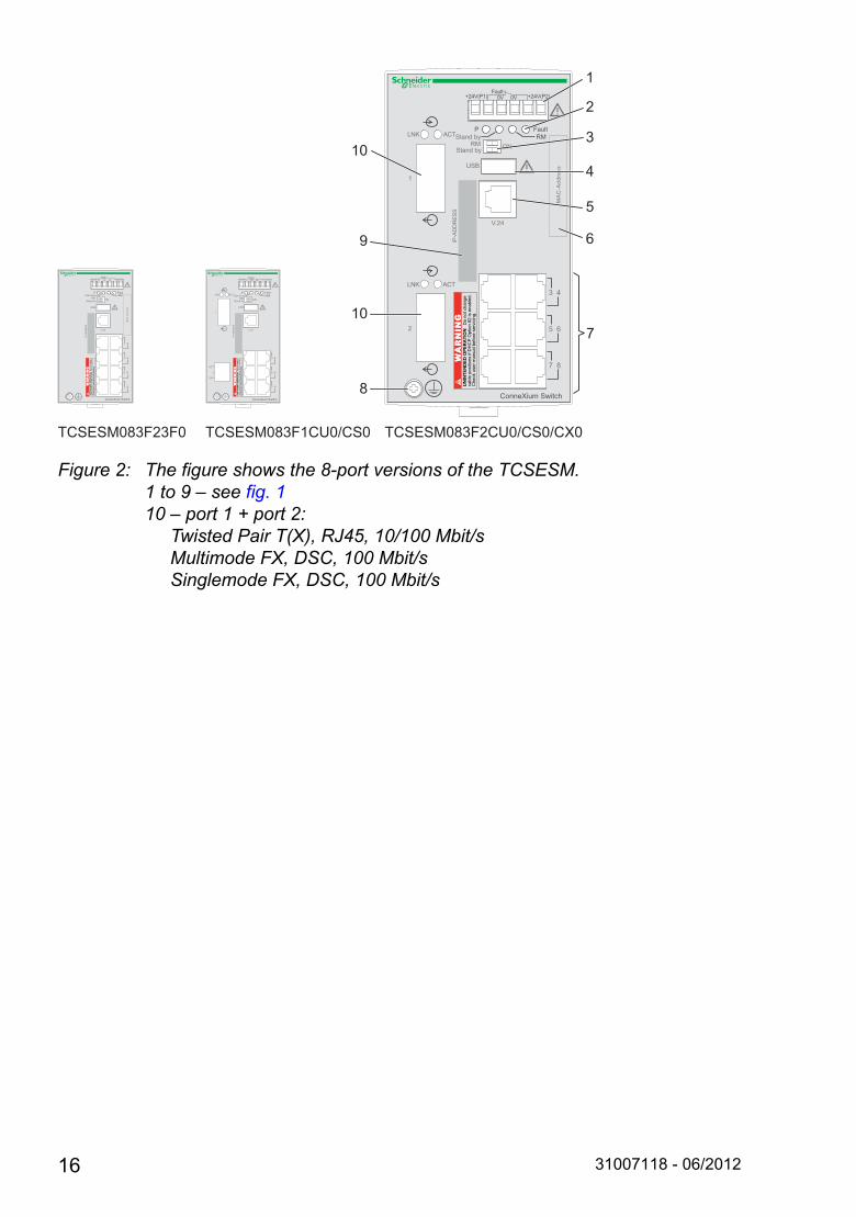
Figure 2: The figure shows the 8-port versions of the TCSESM.1 to 9 – see fig. 110 – port 1 + port 2: Twisted Pair T(X), RJ45, 10/100 Mbit/s Multimode FX, DSC, 100 Mbit/s Singlemode FX, DSC, 100 Mbit/s
V.24
IP-A
DD
RE
SS
3 4
5 6
7 8
ConneXium Switch
WARNING
WARNING
UN
INT
EN
DE
D O
PE
RA
TIO
N D
o no
t cha
nge
cabl
e po
sitio
ns if
DH
CP
Opt
ion
82 is
ena
bled
. C
heck
use
r man
ual b
efor
e se
rvic
ing.
RMP
RM
Fault
Stand by
USB
Stand byON
Fault0V 0V+24V(P1) +24V(P2)
2
LNK ACT
1
LNK ACT
MA
C-A
ddre
ss
TCSESM083F2CU0/CS0/CX0TCSESM083F1CU0/CS0
7
10
10
8
9
TCSESM083F23F0
ConneXium Switch
V.24
IP-A
DD
RE
SS
1 2
3 4
5 6
7 8
WARNING
WARNING
UN
INT
EN
DE
D O
PE
RA
TIO
N D
o no
t cha
nge
cabl
e po
sitio
ns if
DH
CP
Opt
ion
82 is
ena
bled
. C
heck
use
r man
ual b
efor
e se
rvic
ing.
RMP
RM
Fault
Stand by
USB
Stand byON
Fault0V 0V+24V(P1) +24V(P2)
MA
C-A
ddre
ss
MA
C-A
ddre
ss
V.24
IP-A
DD
RE
SS
1
LNK ACT
3 4
5 6
7 8
2
ACT
LNK
ConneXium Switch
WARNING
WARNING
UN
INT
EN
DE
D O
PE
RA
TIO
N D
o no
t cha
nge
cabl
e po
sitio
ns if
DH
CP
Opt
ion
82 is
ena
bled
. C
heck
use
r man
ual b
efor
e se
rvic
ing.
RMP
RM
Fault
Stand by
USB
Stand byON
Fault0V 0V+24V(P1) +24V(P2)
1
2
3
4
6
5
16 31007118 - 06/2012
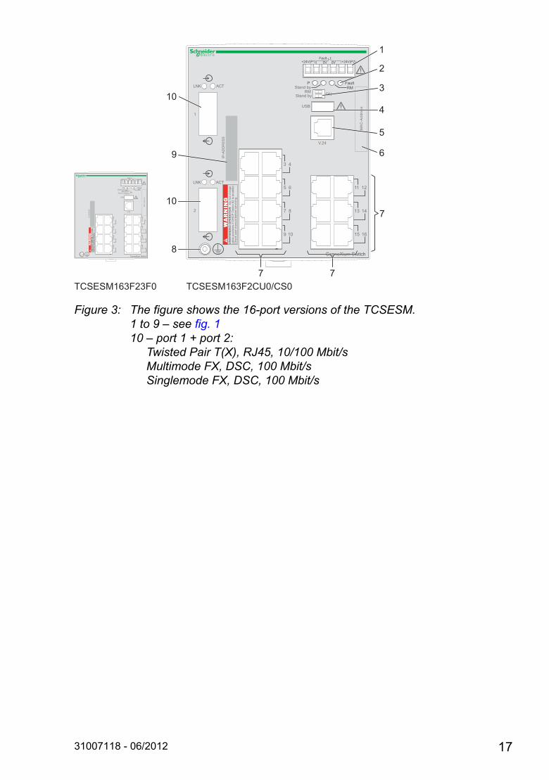
Figure 3: The figure shows the 16-port versions of the TCSESM.1 to 9 – see fig. 110 – port 1 + port 2: Twisted Pair T(X), RJ45, 10/100 Mbit/s Multimode FX, DSC, 100 Mbit/s Singlemode FX, DSC, 100 Mbit/s
2
LNK ACT
1
LNK ACT
ConneXium Switch
RMP
RM
Fault
V.24
Stand by
USB
Stand byON
IP-A
DD
RE
SS
Fault0V 0V+24V(P1) +24V(P2)
3 4
5 6
7 8
9 10
11 12
13 14
15 16
MA
C-A
ddre
ss
WARNING
WARNING
UN
INT
EN
DE
D O
PE
RA
TIO
N D
o no
t cha
nge
cabl
e po
sitio
ns if
DH
CP
Opt
ion
82 is
ena
bled
. C
heck
use
r man
ual b
efor
e se
rvic
ing.
TCSESM163F2CU0/CS0TCSESM163F23F0
7
ConneXium Switch
RMP
RM
Fault
V.24
Stand by
USB
Stand byON
IP-A
DD
RE
SS
Fault0V 0V+24V(P1) +24V(P2)
1 2
3 4
5 6
7 8
9 10
11 12
13 14
15 16
MA
C-A
ddre
ss
WARNING
WARNING
UN
INT
EN
DE
D O
PE
RA
TIO
N D
o no
t cha
nge
cabl
e po
sitio
ns if
DH
CP
Opt
ion
82 is
ena
bled
. C
heck
use
r man
ual b
efor
e se
rvic
ing.
7 7
10
10
8
9
1
2
3
4
6
5
31007118 - 06/2012 17
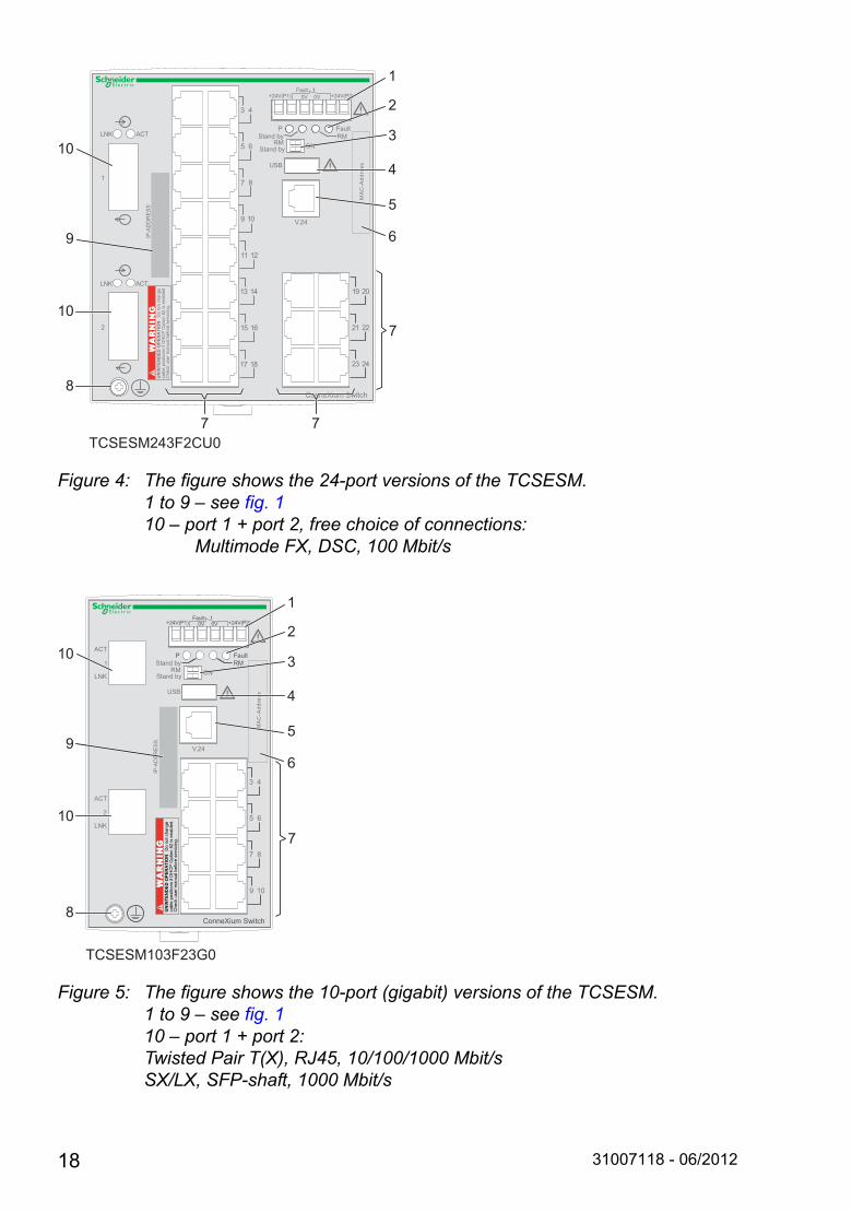
Figure 4: The figure shows the 24-port versions of the TCSESM.1 to 9 – see fig. 110 – port 1 + port 2, free choice of connections: Multimode FX, DSC, 100 Mbit/s
Figure 5: The figure shows the 10-port (gigabit) versions of the TCSESM.1 to 9 – see fig. 110 – port 1 + port 2:Twisted Pair T(X), RJ45, 10/100/1000 Mbit/sSX/LX, SFP-shaft, 1000 Mbit/s
11 12
13 14
15 16
17 18
19 20
21 22
23 24
3 4
5 6
7 8
9 10
RMP
RM
Fault
Stand by
USB
Stand byON
V.24
ConneXium Switch
2
LNK ACT
1
LNK ACT
Fault0V 0V+24V(P1) +24V(P2)
MA
C-A
ddre
ss
IP-A
DD
RE
SS
WARNING
WARNING
UN
INT
EN
DE
D O
PE
RA
TIO
N D
o no
t cha
nge
cabl
e po
sitio
ns if
DH
CP
Opt
ion
82 is
ena
bled
. C
heck
use
r man
ual b
efor
e se
rvic
ing.
TCSESM243F2CU0
7
7 7
10
10
8
9
1
2
3
4
6
5
V.24
IP-A
DD
RE
SS
3 4
5 6
7 8
9 10
RMP
RM
Fault
Stand by
USB
Stand byON
Fault0V 0V+24V(P1) +24V(P2)
2
ACT
LNK
1
ACT
LNK
ConneXium Switch
WARNING
WARNING
UN
INT
EN
DE
D O
PE
RA
TIO
N D
o no
t cha
nge
cabl
e po
sitio
ns if
DH
CP
Opt
ion
82 is
ena
bled
. C
heck
use
r man
ual b
efor
e se
rvic
ing.
MA
C-A
ddre
ss
TCSESM103F23G0
7
10
10
8
9
1
2
3
4
6
5
18 31007118 - 06/2012

2 Assembly and start-up
2.1 Safety instructions
Staff qualification requirementsOnly appropriately qualified staff should work on or near this equipment. Such staff must be thoroughly acquainted with all the hazard messages and maintenance measures contained in these operating instructions.The proper and safe operation of this equipment assumes proper transport, appropriate storage and assembly, and careful operation and maintenance.Qualified staff are persons familiar with setting up, assembling, installation, starting up, and operating this product, and who have appropriate qualifications to cover their activities, such as: knowledge of how to switch circuits and equipment/systems on and
off, ground them, and identify them in accordance with current safety standards
training or instruction in accordance with current safety standards of using and maintaining appropriate safety equipment
first aid training
Recycling noteAfter usage, this product must be disposed of properly as electronic waste, in accordance with the current disposal regulations of your county, state and country.
31007118 - 06/2012 19

2.2 Installing the device
2.2.1 Overview of installationTwo or more devices configured with the same IP address can cause unpredictable operation of your network.
On delivery, the device is ready for operation.
The following steps should be performed to install and configure a switch:
Unpacking and checking Insert data in label area Adjust DIP switch settings Connect the terminal block for voltage supply and signal
contact and connect the supply voltage Install the device on the DIN rail, grounding Install the terminal block, start-up procedure Connecting the data lines
2.2.2 Unpacking and checking Check that the contents of the package are complete (see page 37
“Scope of delivery”). Check the individual parts for transport damage.
WARNINGUNINTENDED EQUIPMENT OPERATION
Establish and maintain a process for assigning unique IP addresses to all devices on the network.
Failure to follow these instructions can result in death, serious injury, or equipment damage.
WARNINGUNINTENDED OPERATION
Do not change cable positions if DHCP Option 82 is enabled. Check the Basic Configuration user manual before servicing (refer to DHCP OPTION 82 topic).
Failure to follow these instructions can result in death, serious injury, or equipment damage.
20 31007118 - 06/2012
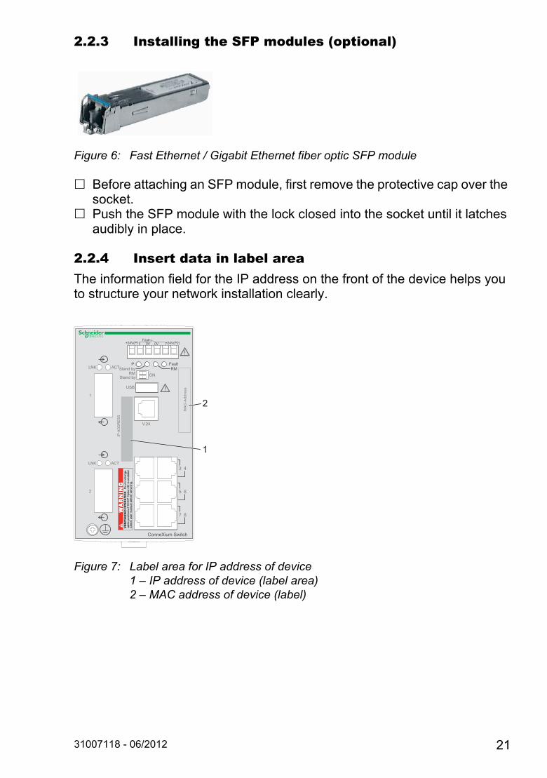
2.2.3 Installing the SFP modules (optional)
Figure 6: Fast Ethernet / Gigabit Ethernet fiber optic SFP module
Before attaching an SFP module, first remove the protective cap over the socket.
Push the SFP module with the lock closed into the socket until it latches audibly in place.
2.2.4 Insert data in label areaThe information field for the IP address on the front of the device helps you to structure your network installation clearly.
Figure 7: Label area for IP address of device1 – IP address of device (label area)2 – MAC address of device (label)
V.24
IP-A
DD
RE
SS
3 4
5 6
7 8
ConneXium Switch
WARNING
WARNING
UN
INT
EN
DE
D O
PE
RA
TIO
N D
o no
t cha
nge
cabl
e po
sitio
ns if
DH
CP
Opt
ion
82 is
ena
bled
. C
heck
use
r man
ual b
efor
e se
rvic
ing.
RMP
RM
Fault
Stand by
USB
Stand byON
Fault0V 0V+24V(P1) +24V(P2)
2
LNK ACT
1
LNK ACT
MA
C-A
ddre
ss
2
1
31007118 - 06/2012 21
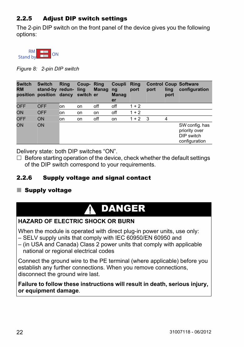
2.2.5 Adjust DIP switch settingsThe 2-pin DIP switch on the front panel of the device gives you the following options:
Figure 8: 2-pin DIP switch
Delivery state: both DIP switches “ON”. Before starting operation of the device, check whether the default settings
of the DIP switch correspond to your requirements.
2.2.6 Supply voltage and signal contact
Supply voltage
SwitchRMposition
Switchstand-byposition
Ringredun-dancy
Coup-ling switch
RingManager
Coupling Manager
Ringport
Controlport
Coupling port
Software configuration
OFF OFF on on off off 1 + 2ON OFF on on on off 1 + 2OFF ON on on off on 1 + 2 3 4ON ON SW config. has
priority over DIP switch configuration
DANGERHAZARD OF ELECTRIC SHOCK OR BURN
When the module is operated with direct plug-in power units, use only: – SELV supply units that comply with IEC 60950/EN 60950 and – (in USA and Canada) Class 2 power units that comply with applicable national or regional electrical codes
Connect the ground wire to the PE terminal (where applicable) before you establish any further connections. When you remove connections, disconnect the ground wire last.
Failure to follow these instructions will result in death, serious injury, or equipment damage.
RMStand by ON
22 31007118 - 06/2012
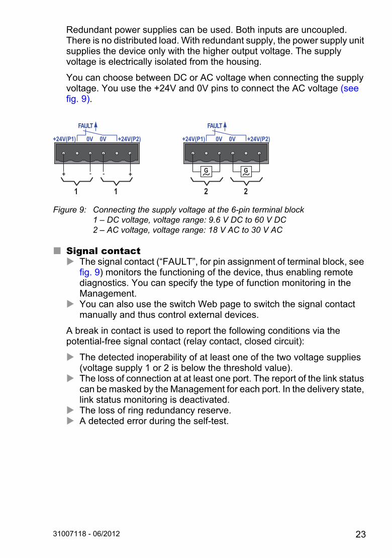
Redundant power supplies can be used. Both inputs are uncoupled. There is no distributed load. With redundant supply, the power supply unit supplies the device only with the higher output voltage. The supply voltage is electrically isolated from the housing.
You can choose between DC or AC voltage when connecting the supply voltage. You use the +24V and 0V pins to connect the AC voltage (see fig. 9).
Figure 9: Connecting the supply voltage at the 6-pin terminal block1 – DC voltage, voltage range: 9.6 V DC to 60 V DC2 – AC voltage, voltage range: 18 V AC to 30 V AC
Signal contact The signal contact (“FAULT”, for pin assignment of terminal block, see
fig. 9) monitors the functioning of the device, thus enabling remote diagnostics. You can specify the type of function monitoring in the Management.
You can also use the switch Web page to switch the signal contact manually and thus control external devices.
A break in contact is used to report the following conditions via the potential-free signal contact (relay contact, closed circuit):
The detected inoperability of at least one of the two voltage supplies (voltage supply 1 or 2 is below the threshold value).
The loss of connection at at least one port. The report of the link status can be masked by the Management for each port. In the delivery state, link status monitoring is deactivated.
The loss of ring redundancy reserve. A detected error during the self-test.
FAULT
G G
+24V(P1) 0V 0V +24V(P2)
FAULT
+24V(P1) 0V 0V +24V(P2)
+ - - +
1 1 2 2
31007118 - 06/2012 23
The following condition is also reported in RM mode: Ring redundancy reserve is available. On delivery, there is no ring
redundancy monitoring.
Pull the terminal block off the device and connect the power supply and signal lines.
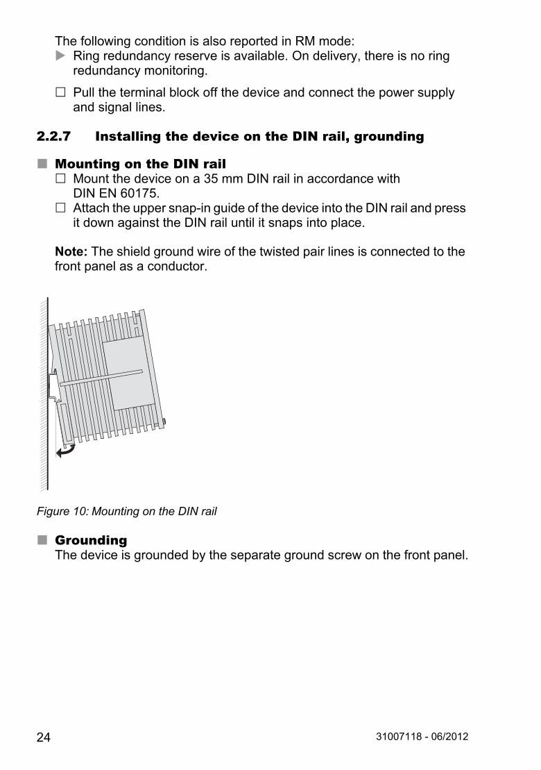
2.2.7 Installing the device on the DIN rail, grounding
Mounting on the DIN rail Mount the device on a 35 mm DIN rail in accordance with
DIN EN 60175. Attach the upper snap-in guide of the device into the DIN rail and press
it down against the DIN rail until it snaps into place.
Note: The shield ground wire of the twisted pair lines is connected to the front panel as a conductor.
Figure 10: Mounting on the DIN rail
GroundingThe device is grounded by the separate ground screw on the front panel.
24 31007118 - 06/2012

2.2.8 Dimension drawings
Figure 11: 4 Port Versions
Figure 12: 8 and 10 Port Versions
31007118 - 06/2012 25

Figure 13: 16 and 24 Port Versions
2.2.9 Installing the terminal block, start-up procedure Mount the terminal block for the voltage supply and signal contact on the
front of the device by snapping the lock into place.
Connecting the voltage supply via the terminal block starts the operation of the device.
2.2.10 Connecting the data linesYou can connect terminal devices and other segments on the ports of the device via twisted pair cables or F/O cables.
Install the data lines according to your requirements.
10/100 Mbit/s twisted pair connection These connections are RJ45 sockets.10/100 Mbit/s TP ports enable the connection of terminal devices or independent network segments according to the IEEE 802.3 10BASE-T/100BASE-TX standard. These ports support: Autonegotiation
(data rate and duplex mode) Autopolarity Autocrossing (if autonegotiation is activated)
26 31007118 - 06/2012
100 Mbit/s half-duplex mode, 100 Mbit/s full duplex mode 10 Mbit/s half-duplex mode, 10 Mbit/s full duplex modeDelivery state: autonegotiation activatedThe socket housing is electrically connected to the front panel.
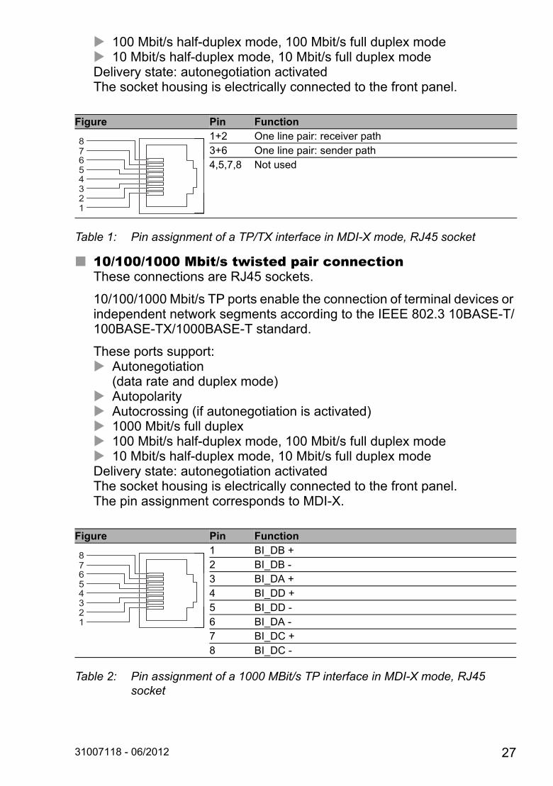
10/100/1000 Mbit/s twisted pair connectionThese connections are RJ45 sockets.
10/100/1000 Mbit/s TP ports enable the connection of terminal devices or independent network segments according to the IEEE 802.3 10BASE-T/100BASE-TX/1000BASE-T standard.
These ports support: Autonegotiation
(data rate and duplex mode) Autopolarity Autocrossing (if autonegotiation is activated) 1000 Mbit/s full duplex 100 Mbit/s half-duplex mode, 100 Mbit/s full duplex mode 10 Mbit/s half-duplex mode, 10 Mbit/s full duplex modeDelivery state: autonegotiation activatedThe socket housing is electrically connected to the front panel.The pin assignment corresponds to MDI-X.
Figure Pin Function1+2 One line pair: receiver path3+6 One line pair: sender path4,5,7,8 Not used
Table 1: Pin assignment of a TP/TX interface in MDI-X mode, RJ45 socket
Figure Pin Function1 BI_DB +2 BI_DB -3 BI_DA +4 BI_DD +5 BI_DD -6 BI_DA -7 BI_DC +8 BI_DC -
Table 2: Pin assignment of a 1000 MBit/s TP interface in MDI-X mode, RJ45 socket
87654321
87654321
31007118 - 06/2012 27
100 Mbit/s F/O connectionThese connections are DSC connectors.100 MBit/s F/O ports enable the connection of terminal devices or independent network segments in compliance with the IEEE 802.3 100BASE-FX standard. These ports support: Full or half duplex modeDelivery state: full duplex FDX
Note: Make sure that the SM ports are only connected with SM ports, and MM ports only with MM ports.
1 Gbit/s F/O connectionThese ports are SFP slots.1 Gbit/s F/O ports enable the connection of terminal devices or independent network segments according to the IEEE 802.3 1000BASE-SX/1000BASE-LX standard.These ports support: Autonegotiation Full duplex modeDelivery state: autonegotiation activated
Note: Make sure that the LH ports are only connected with LH ports, SX ports are only connected with SX ports, and LX ports only with LX ports.
28 31007118 - 06/2012
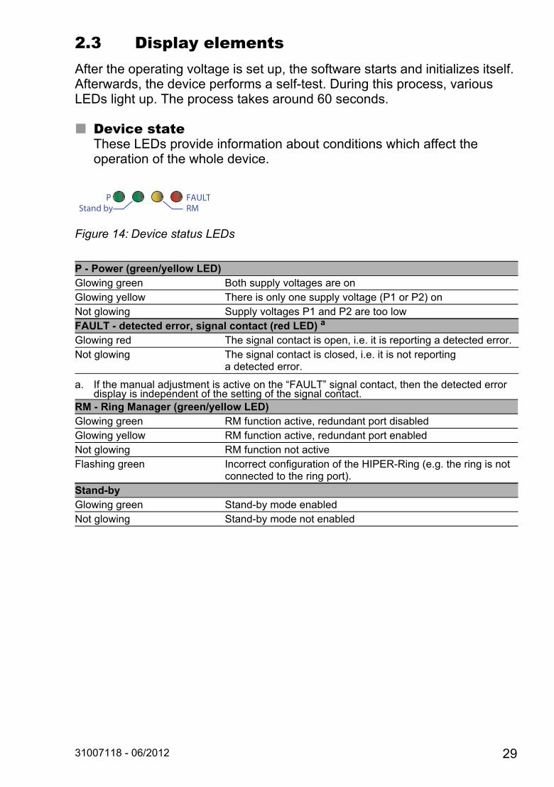
2.3 Display elementsAfter the operating voltage is set up, the software starts and initializes itself. Afterwards, the device performs a self-test. During this process, various LEDs light up. The process takes around 60 seconds.
Device stateThese LEDs provide information about conditions which affect the operation of the whole device.
Figure 14: Device status LEDs
P - Power (green/yellow LED)Glowing green Both supply voltages are onGlowing yellow There is only one supply voltage (P1 or P2) onNot glowing Supply voltages P1 and P2 are too lowFAULT - detected error, signal contact (red LED) a
a. If the manual adjustment is active on the “FAULT” signal contact, then the detected error display is independent of the setting of the signal contact.
Glowing red The signal contact is open, i.e. it is reporting a detected error.Not glowing The signal contact is closed, i.e. it is not reporting
a detected error.
RM - Ring Manager (green/yellow LED) Glowing green RM function active, redundant port disabledGlowing yellow RM function active, redundant port enabledNot glowing RM function not activeFlashing green Incorrect configuration of the HIPER-Ring (e.g. the ring is not
connected to the ring port).Stand-byGlowing green Stand-by mode enabledNot glowing Stand-by mode not enabled
PStand by
FAULTRM
31007118 - 06/2012 29
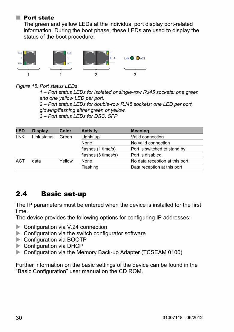
Port stateThe green and yellow LEDs at the individual port display port-related information. During the boot phase, these LEDs are used to display the status of the boot procedure.
Figure 15: Port status LEDs1 – Port status LEDs for isolated or single-row RJ45 sockets: one green and one yellow LED per port.2 – Port status LEDs for double-row RJ45 sockets: one LED per port, glowing/flashing either green or yellow.3 – Port status LEDs for DSC, SFP
2.4 Basic set-upThe IP parameters must be entered when the device is installed for the first time. The device provides the following options for configuring IP addresses:
Configuration via V.24 connection Configuration via the switch configurator software Configuration via BOOTP Configuration via DHCP Configuration via the Memory Back-up Adapter (TCSEAM 0100)
Further information on the basic settings of the device can be found in the “Basic Configuration” user manual on the CD ROM.
LED Display Color Activity MeaningLNK Link status Green Lights up Valid connection
None No valid connectionflashes (1 time/s) Port is switched to stand byflashes (3 times/s) Port is disabled
ACT data Yellow None No data reception at this portFlashing Data reception at this port
LNK ACT
ACT
1
LNK
1
LNK
1
ACT
1 32
30 31007118 - 06/2012

Default settings IP address: The device looks for the IP address using DHCP Password for management:
Login: user; password: public (read only)Login: admin; password: private (read and write)
V.24 data rate: 9,600 Baud Ring redundancy: disabled Ethernet ports: link status is not evaluated (signal contact) Optical 100 Mbit/s ports: 100 Mbit/s, full duplex
All other ports: autonegotiation Ring Manager disabled (DIP switch RM and stand-by: ON) Stand-by coupling disabled (DIP switch RM and stand-by: ON)
Port 4 = control port, port 3 = coupling port for red. Ring coupling Rapid Spanning Tree enabled
USB interfaceThe USB socket has an interface for the local connection of a Memory Back-up Adapter (EAM). The EAM is used for saving/loading the configuration data and diagnostic information, and for loading the software.
Figure Pin Operation1 VCC (VBus)2 − Data3 + Data4 Ground (GND)
Table 3: Pin assignment of the USB interface
1 2 43
31007118 - 06/2012 31
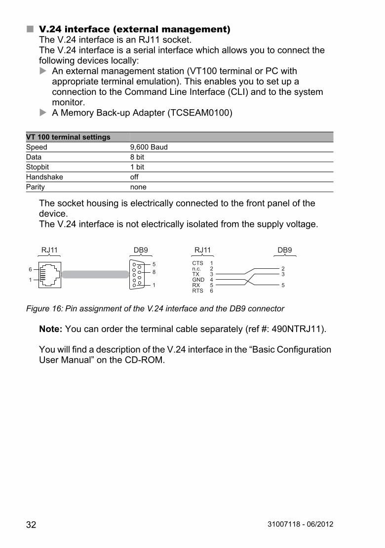
V.24 interface (external management)The V.24 interface is an RJ11 socket.The V.24 interface is a serial interface which allows you to connect the following devices locally: An external management station (VT100 terminal or PC with
appropriate terminal emulation). This enables you to set up a connection to the Command Line Interface (CLI) and to the system monitor.
A Memory Back-up Adapter (TCSEAM0100)
The socket housing is electrically connected to the front panel of the device. The V.24 interface is not electrically isolated from the supply voltage.
Figure 16: Pin assignment of the V.24 interface and the DB9 connector
Note: You can order the terminal cable separately (ref #: 490NTRJ11).
You will find a description of the V.24 interface in the “Basic Configuration User Manual” on the CD-ROM.
VT 100 terminal settingsSpeed 9,600 BaudData 8 bitStopbit 1 bitHandshake offParity none
11
85
6 23
5
123456
CTSn.c.TXGNDRXRTS
RJ11 DB9 RJ11 DB9
32 31007118 - 06/2012
2.5 Maintenance Depending on the degree of pollution in the operating environment, check
at regular intervals that the ventilation slots in the device are not obstructed.Operate this device according to the specifications (see “Technical data”).
2.6 Disassembly
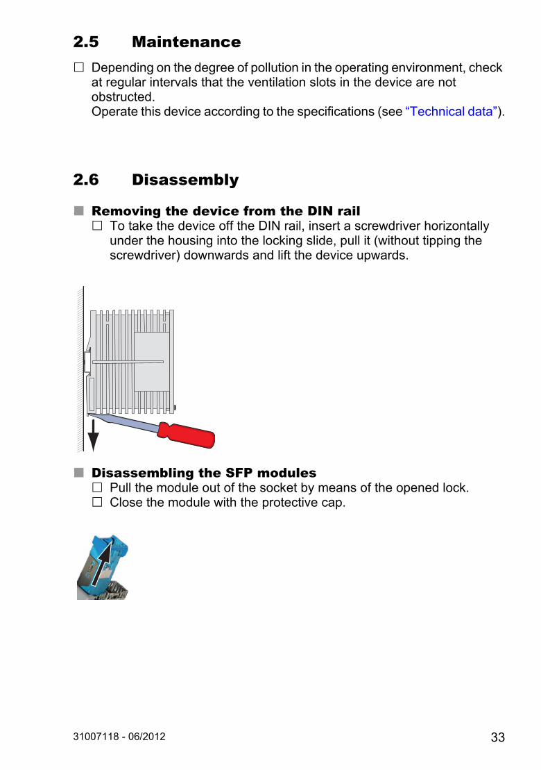
Removing the device from the DIN rail To take the device off the DIN rail, insert a screwdriver horizontally
under the housing into the locking slide, pull it (without tipping the screwdriver) downwards and lift the device upwards.
Disassembling the SFP modules Pull the module out of the socket by means of the opened lock. Close the module with the protective cap.
31007118 - 06/2012 33
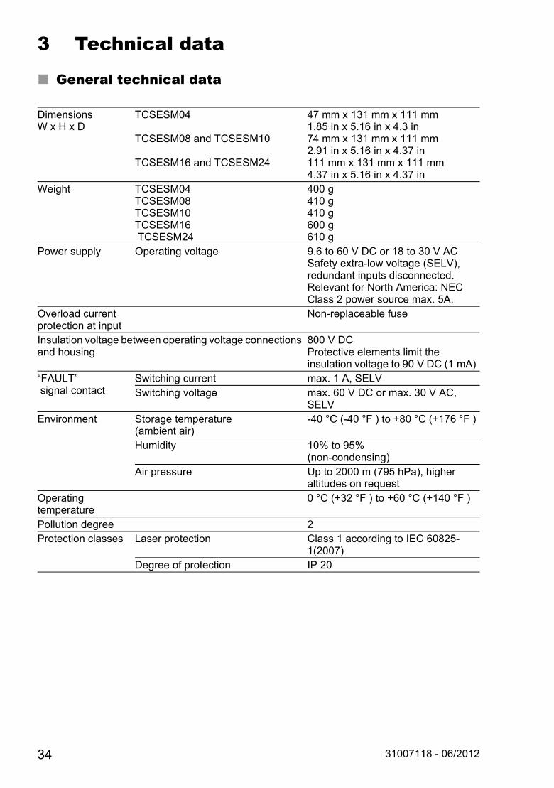
3 Technical data
General technical data
Dimensions W x H x D
TCSESM04
TCSESM08 and TCSESM10
TCSESM16 and TCSESM24
47 mm x 131 mm x 111 mm1.85 in x 5.16 in x 4.3 in74 mm x 131 mm x 111 mm2.91 in x 5.16 in x 4.37 in111 mm x 131 mm x 111 mm4.37 in x 5.16 in x 4.37 in
Weight TCSESM04 TCSESM08 TCSESM10TCSESM16 TCSESM24
400 g410 g410 g600 g610 g
Power supply Operating voltage 9.6 to 60 V DC or 18 to 30 V ACSafety extra-low voltage (SELV), redundant inputs disconnected.Relevant for North America: NEC Class 2 power source max. 5A.
Overload current protection at input
Non-replaceable fuse
Insulation voltage between operating voltage connections and housing
800 V DCProtective elements limit the insulation voltage to 90 V DC (1 mA)
“FAULT” signal contact
Switching current max. 1 A, SELVSwitching voltage max. 60 V DC or max. 30 V AC,
SELVEnvironment Storage temperature
(ambient air)-40 °C (-40 °F ) to +80 °C (+176 °F )
Humidity 10% to 95%(non-condensing)
Air pressure Up to 2000 m (795 hPa), higher altitudes on request
Operating temperature
0 °C (+32 °F ) to +60 °C (+140 °F )
Pollution degree 2Protection classes Laser protection Class 1 according to IEC 60825-
1(2007)Degree of protection IP 20
34 31007118 - 06/2012
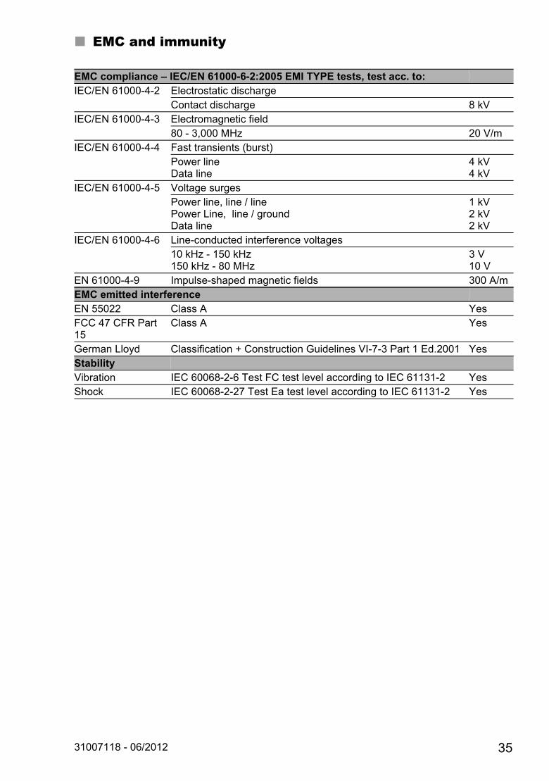
EMC and immunity
EMC compliance – IEC/EN 61000-6-2:2005 EMI TYPE tests, test acc. to: IEC/EN 61000-4-2 Electrostatic discharge
Contact discharge 8 kVIEC/EN 61000-4-3 Electromagnetic field
80 - 3,000 MHz 20 V/mIEC/EN 61000-4-4 Fast transients (burst)
Power lineData line
4 kV4 kV
IEC/EN 61000-4-5 Voltage surgesPower line, line / linePower Line, line / groundData line
1 kV2 kV2 kV
IEC/EN 61000-4-6 Line-conducted interference voltages10 kHz - 150 kHz150 kHz - 80 MHz
3 V10 V
EN 61000-4-9 Impulse-shaped magnetic fields 300 A/mEMC emitted interferenceEN 55022 Class A YesFCC 47 CFR Part 15
Class A Yes
German Lloyd Classification + Construction Guidelines VI-7-3 Part 1 Ed.2001 YesStabilityVibration IEC 60068-2-6 Test FC test level according to IEC 61131-2 YesShock IEC 60068-2-27 Test Ea test level according to IEC 61131-2 Yes
31007118 - 06/2012 35
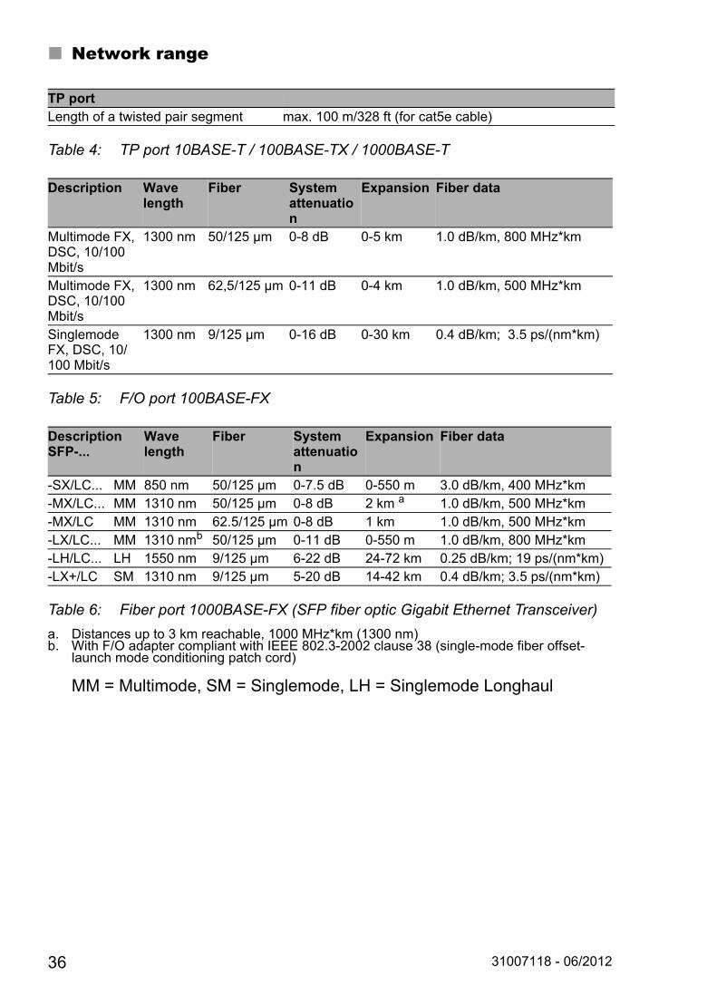
Network range
MM = Multimode, SM = Singlemode, LH = Singlemode Longhaul
TP portLength of a twisted pair segment max. 100 m/328 ft (for cat5e cable)
Table 4: TP port 10BASE-T / 100BASE-TX / 1000BASE-T
Description Wave length
Fiber System attenuation
Expansion Fiber data
Multimode FX, DSC, 10/100 Mbit/s
1300 nm 50/125 µm 0-8 dB 0-5 km 1.0 dB/km, 800 MHz*km
Multimode FX, DSC, 10/100 Mbit/s
1300 nm 62,5/125 µm 0-11 dB 0-4 km 1.0 dB/km, 500 MHz*km
Singlemode FX, DSC, 10/100 Mbit/s
1300 nm 9/125 µm 0-16 dB 0-30 km 0.4 dB/km; 3.5 ps/(nm*km)
Table 5: F/O port 100BASE-FX
DescriptionSFP-...
Wave length
Fiber System attenuation
Expansion Fiber data
-SX/LC... MM 850 nm 50/125 µm 0-7.5 dB 0-550 m 3.0 dB/km, 400 MHz*km-MX/LC... MM 1310 nm 50/125 µm 0-8 dB 2 km a
a. Distances up to 3 km reachable, 1000 MHz*km (1300 nm)
1.0 dB/km, 500 MHz*km-MX/LC MM 1310 nm 62.5/125 µm 0-8 dB 1 km 1.0 dB/km, 500 MHz*km-LX/LC... MM 1310 nmb
b. With F/O adapter compliant with IEEE 802.3-2002 clause 38 (single-mode fiber offset-launch mode conditioning patch cord)
50/125 µm 0-11 dB 0-550 m 1.0 dB/km, 800 MHz*km-LH/LC... LH 1550 nm 9/125 µm 6-22 dB 24-72 km 0.25 dB/km; 19 ps/(nm*km)-LX+/LC SM 1310 nm 9/125 µm 5-20 dB 14-42 km 0.4 dB/km; 3.5 ps/(nm*km)
Table 6: Fiber port 1000BASE-FX (SFP fiber optic Gigabit Ethernet Transceiver)
36 31007118 - 06/2012

Power consumption/power output
Recommended fuses
Scope of delivery
Device name Device model Maximum power consumption
Power output
TCSESM04 2xTX port 5.3 W 18.1 Btu (IT)/hTCSESM04 1xFX port, 1xTX port 6.5 W 22.2 Btu (IT)/hTCSESM04 2xFX port 7.7 W 26.3 Btu (IT)/hTCSESM08 2xTX port 5.3 W 18.1 Btu (IT)/hTCSESM08 1xFX port, 1xTX port 6.5 W 22.2 Btu (IT)/hTCSESM08 2xFX port 7.7 W 26.3 Btu (IT)/hTCSESM10 (with gigabit ports) 2xTX port 8.9 W 30.4 Btu (IT)/hTCSESM10 (with gigabit ports) 2xFX port 8.3 W 28.4 Btu (IT)/hTCSESM16 2xTX port 9.4 W 32.1 Btu (IT)/hTCSESM16 2xFX port 11.8 W 40.3 Btu (IT)/h TCSESM24 2xFX port 14.5 W 52.9 Btu (IT)/h
Table 7: Power input/output for the TCSESM devices
Device name FuseTCSESM04xx 1.5 A, slow/delay fuseTCSESM08xx 1.5 A, slow/delay fuseTCSESM10xx 2.0 A, slow/delay fuseTCSESM16xx 2.0 A, slow/delay fuse TCSESM24xx 3.0 A, slow/delay fuse
Device Scope of deliveryTCSESMxx Device
Terminal block for supply voltage and signal contactCD-ROM (includes user technical documentation)
31007118 - 06/2012 37

Order numbers/product description
Part Number Part Number Description4 Port Version TCSESM043F23F0 4 10/100 TX Managed
TCSESM043F1CU0 3 10/100 TX 1 100 FX-MM ManagedTCSESM043F2CU0 2 10/100 TX 2 100 FX-MM ManagedTCSESM043F1CS0 3 10/100 TX 1 100 FX-SM ManagedTCSESM043F2CS0 2 10/100 TX 2 100 FX-SM Managed
8 Port Version TCSESM083F23F0 8 10/100 TX ManagedTCSESM083F1CU0 7 10/100 TX 1 100 FX-MM ManagedTCSESM083F2CU0 6 10/100 TX 2 100 FX-MM ManagedTCSESM083F1CS0 7 10/100 TX 1 100 FX-SM ManagedTCSESM083F2CS0 6 10/100 TX 2 100 FX-SM Managed
16 Port Version TCSESM163F23F0 16 10/100 TX ManagedTCSESM163F2CU0 14 10/100 TX 2 100 FX-MM ManagedTCSESM163F2CS0 14 10/100 TX 2 100 FX-SM Managed
24 Port Version TCSESM243F2CU0 22 10/100 TX 2 100 FX-MM ManagedGigabit - 10 Port Version
TCSESM103F23G0 8 10/100 TX 2 10/100/1000 TX ManagedTCSESM103F2LG0 8 10/100 TX, 2 1000 SFP (fiber) Managed
Note: This product ships with open sockets (SFP) on the fiber ports. In order to use these ports, order 1 or 2 fiber modules in any combination (see below).
Fiber Media Modules for Gigabit
TCSEAAF1LFU00 fiber module SFP-SX/LCTCSEAAF1LFS00 fiber module SFP-LX/LCTCSEAAF1LFH00 fiber module SFP-LH/LC
Accessories TCSEAM0100 Adapter Memory Back-up Adapter490NTRJ11 Cable Terminal 490NTRJ11 cable
38 31007118 - 06/2012

Underlying norms and standards
Certifications
The TCSESM switches have CE certifications.
StandardEN 10155 Declaration (railroad)EN 50121-4 Railway applications - EMC - emitted interference and interference
immunity for signal and telecommunication systemsEN 55022 IT equipment – radio interference characteristicsEN 61000-6-2 Generic norm – immunity in industrial environmentsEN 61131-2 Programmable logic controllersFCC 47 CFR Part 15 Code of Federal RegulationsEN 60950-1 Safety for the installation of IT equipmentIEC/EN 61850-3 Communications networks and systems in substationsIEEE 1613 Standard Environment and Testing Requirements for
Communication Networking Devices in Electric Power Substations
StandardcUL 508 / CSA C22.2 No.142
Safety for Industrial Control Equipment
ISA 12.12.01 / CSA C22.2 No.213
Electrical Equipment for Use in Class I and Class II, Div.2 and Class III Hazardous (Classified) Locations
Germanischer Lloyd Ship Applications - Classification and Construction Guidelines VI-7-3 Part 1 Ed.2003
31007118 - 06/2012 39

40 31007118 - 06/2012