Tcpw Cadd Manual 03-01-10
74
CADD & CIVIL 3D USER GUIDE LINES 1 THURSTON COUNTY PUBLIC WORKS DEPARTMENT Design and Construction Division CADD & Civil 3D User Guidelines v3.0_12_29_09
Transcript of Tcpw Cadd Manual 03-01-10
8/8/2019 Tcpw Cadd Manual 03-01-10
http://slidepdf.com/reader/full/tcpw-cadd-manual-03-01-10 1/73
C A D D & C I V I L 3 D U S E R G U I D E L I N E S
1
THURSTON COUNTY PUBLIC WORKS DEPARTMENT
Design and Construction Division
CADD & Civil 3D UserGuidelines
v3.0_12_29_09
8/8/2019 Tcpw Cadd Manual 03-01-10
http://slidepdf.com/reader/full/tcpw-cadd-manual-03-01-10 2/73
C A D D & C I V I L 3 D U S E R G U I D E L I N E S
2
T H U R S T O N C O U N T Y P U B L I C W O R K S D E P A R T M E N T
D E S I G N A N D C O N S T R U C T I O N D I V I S I O N
CADD & Civil 3D User Guidelines
Prepared for: Thurston County Public Works Department
Design & Construction Division
8/8/2019 Tcpw Cadd Manual 03-01-10
http://slidepdf.com/reader/full/tcpw-cadd-manual-03-01-10 3/73
C A D D & C I V I L 3 D U S E R G U I D E L I N E S
3
Table of Contents
Chapt er 1 - Thurst on County Publ ic Work s CADD & Civ i l 3D
User Guidel ines
• User Responsibilities
• General Care
• Version Control
• Reference Files
• Basis of Guidelines
• AutoCAD Layers
• AutoCAD Lineweights
• Plot Styles – Color or Style Dependency• Types of Plot Style Tables
• AutoCAD Sheet Sets
• Archive and eTransmit
Chapter 2 - Pro jec t Star t up
• Setting TC_PD_C3D.dwt File As the Default Template
Chapt er 3 - Creat ing Project Draw ing ( .dw g) Fi les
• Drawings Based on Your Template
• Incorporating Civil 3D Drawings Created using a Different Template
• Incorporating Non-AutoCAD or Non-Civil 3D Drawings
Chapt er 4 - Creat ing Topograp hic Survey Draw ings • Starting a New Drawing
• Surface Modeling Process
• Saving Your Drawing
8/8/2019 Tcpw Cadd Manual 03-01-10
http://slidepdf.com/reader/full/tcpw-cadd-manual-03-01-10 4/73

8/8/2019 Tcpw Cadd Manual 03-01-10
http://slidepdf.com/reader/full/tcpw-cadd-manual-03-01-10 5/73
C A D D & C I V I L 3 D U S E R G U I D E L I N E S
5
Chapter 9 - Creat ing V iew Frames & Generat ing Sheet Sets
• Creating View Frames & View Frame Groups (Ribbon Interface: Annotate Tab
Create View Frames)
• Creating Sheets & Sheet Sets (Ribbon Interface: Create Sheets)
8/8/2019 Tcpw Cadd Manual 03-01-10
http://slidepdf.com/reader/full/tcpw-cadd-manual-03-01-10 6/73
C A D D & C I V I L 3 D U S E R G U I D E L I N E S
6
Appendix
Appendix A – Reference & Pro jec t Fi le Names
Appendix B – Layer Nam ing
Appendix C – Fie ld Code & L inew ork Def in i t ion
Appendix D – Dat a Shortc ut Work f low
• Creating the Data Shortcut
• Creating the Data Shortcut Reference
Appendix E – Creat ing a Survey Datab ase
• New Survey Database
• Populating the Survey Database
8/8/2019 Tcpw Cadd Manual 03-01-10
http://slidepdf.com/reader/full/tcpw-cadd-manual-03-01-10 7/73
C A D D & C I V I L 3 D U S E R G U I D E L I N E S
7
Introduction
This document outlines Thurston County Design & Construction AutoCAD and Civil 3D guidelines.
hurston County Design and Construction perform a high level engineering design and
construction services. County personnel primarily use Autodesk AutoCAD and Civil 3Dsoftware to prepare project plans. This document addresses CADD and Civil 3Dguidelines and standards, and also compatibility issues between the two products.
These standards are intended to be neither static nor all-inclusive and thus will be updated andenhanced as appropriate. Suggestion for improvements are strongly encourage so that subsequentupdates to this manual will reflect both the input and needs of the CADD user.
Users Responsibilities
Adherence to the standards and procedures contained in this manual is essential in
preserving a homogeneous character in drawings issued by your agency or firm, and inincreasing the efficient use of project time and management. This uniformity allows
information to be correctly keyed, added and displayed at any phase in the project.
Modifications of the standards and procedures in this manual may be necessary for specific
situations. Submit the required temporary modifications in memo form to the CADD
Manager. Do not make arbitrary changes without prior approval.
Submit requests for permanent changes in memo form to the CADD Manager, for review
and possible inclusion in this manual. Requests for deviation shall document (1) why the
current procedure or standard is inapplicable or ineffective; (2) what the proposed deviation
or change should be; and (3) how it would improve the CADD standards or procedures andthe overall productivity.
The most efficient use of AutoCAD is not necessarily in the initial creation of a file, but in
the ability to reuse the file or any part of the file at a future date. The true meaning of
CADD productivity is embodied in not having to do the old job again, rather than simply
doing the old job faster. As an example, the reuse and modification of "Prototype Drawings"
can yield a very efficient use of project time and economics. On a broad scale this can be
Chapter
1
T
8/8/2019 Tcpw Cadd Manual 03-01-10
http://slidepdf.com/reader/full/tcpw-cadd-manual-03-01-10 8/73
C A D D & C I V I L 3 D U S E R G U I D E L I N E S
8
very productive; however, the reuse process must not end here. Each user must continually
examine the reusability of any information in a current file. The massing of information in
differing libraries will take time and effort on the part of the users and computer
management staff; however, future dividends of this endeavor will be advantageous.
General Care
Extreme care should be taken in the overall maintenance of both computer hardware and
software. In the case of software, a general cleanup will be needed if the user encounters a
system "lock-up", "crash" or the display of a systems error. For this cleanup, the user should
immediately notify the MIS. In the case of computer hardware, every effort should be made
to keep the keyboard, monitor and CPU free from foreign substances that may be
detrimental to the system. Eating or drinking over or near any computer equipment is not
recommended. In addition, the general area around each workstation should be maintained
in a neat and orderly manner. ii
Reference Files & Project Files
Reference files are files that are commonly shared internally, with consultants, and outside
agencies. Reference files may consist of prototype data files for Civil 3D, standard borders,
project logos, standard border text, and background drawings. These files are to be used as
provided without modification to name or contents. Only the person providing the master
source of the Reference files should modify them.
Project files are created per project and are stored in the specific project folder on the
network. Project files may consist of AutoCAD & Civil 3D files, sheet set files, PDF or
DWF files, and design application files.
8/8/2019 Tcpw Cadd Manual 03-01-10
http://slidepdf.com/reader/full/tcpw-cadd-manual-03-01-10 9/73
C A D D & C I V I L 3 D U S E R G U I D E L I N E S
9
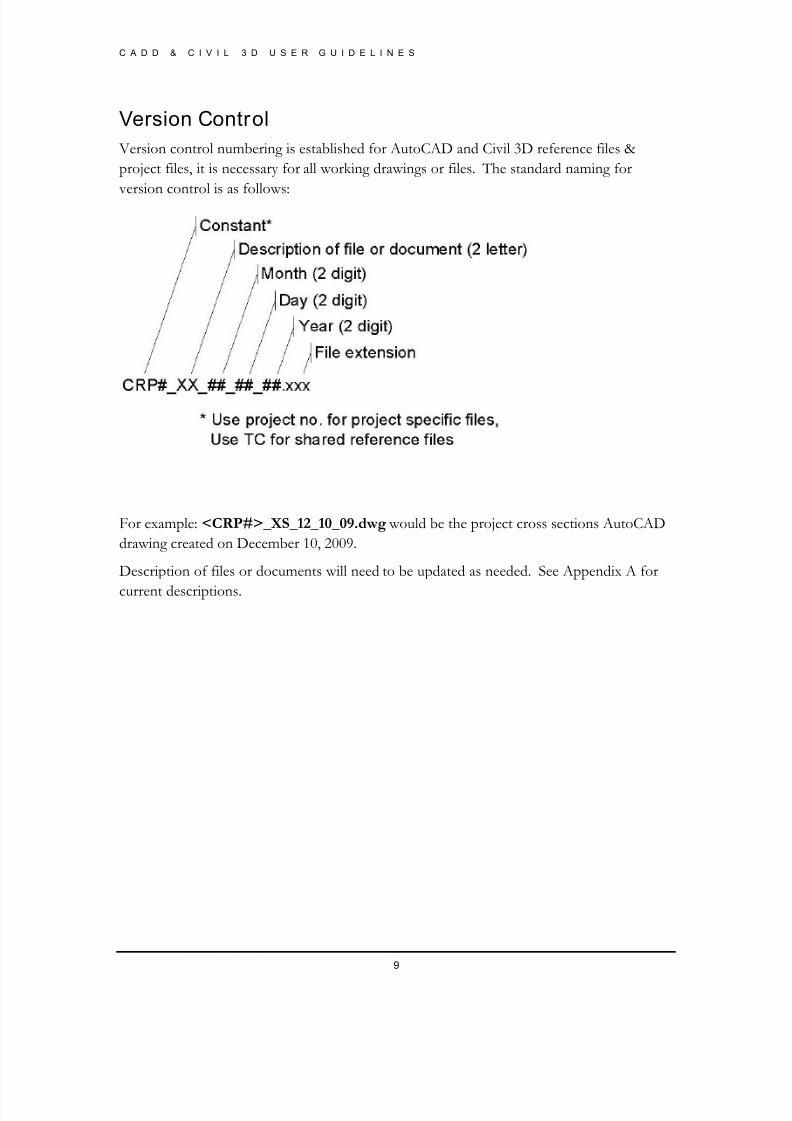
Version Control
Version control numbering is established for AutoCAD and Civil 3D reference files &
project files, it is necessary for all working drawings or files. The standard naming for
version control is as follows:
For example: <CRP#>_XS_12_10_09.dwg would be the project cross sections AutoCAD
drawing created on December 10, 2009.
Description of files or documents will need to be updated as needed. See Appendix A for
current descriptions.
8/8/2019 Tcpw Cadd Manual 03-01-10
http://slidepdf.com/reader/full/tcpw-cadd-manual-03-01-10 10/73
C A D D & C I V I L 3 D U S E R G U I D E L I N E S
10
Referenc e Fi les
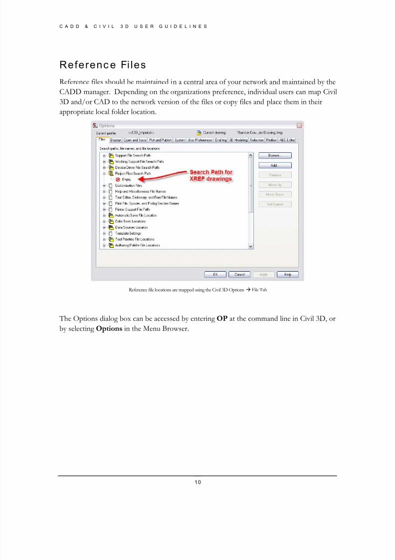
Reference files should be maintained in a central area of your network and maintained by the
CADD manager. Depending on the organizations preference, individual users can map Civil
3D and/or CAD to the network version of the files or copy files and place them in their
appropriate local folder location.
Reference file locations are mapped using the Civil 3D Options File Tab
The Options dialog box can be accessed by entering OP at the command line in Civil 3D, or
by selecting Options in the Menu Browser.
8/8/2019 Tcpw Cadd Manual 03-01-10
http://slidepdf.com/reader/full/tcpw-cadd-manual-03-01-10 11/73
C A D D & C I V I L 3 D U S E R G U I D E L I N E S
11
CAD Guidelines
CAD guidelines and standards are a necessity to maintain drawing consistency throughout an organization.
Basis of Guidelines
The guidelines have been developed referring to the Washington State Chapter of APWA standardsiii. The APWA standards have been modified in order to suit Thurston County Design,
Construction, and Survey business processes.
These standards have been developed for use by public works agencies, utility districts and
consulting engineers working with Thurston County. Although they are primarily designed for use
on computer-generated drawings, the symbols and linetypes should be used on manually drawnplans to maintain consistency.
AutoCAD Layers
Thurston County prototype drawing includes all layers that are normally used for survey
topographical data, and design. Layer conventions are based on four-part layer names to allow the
user to control layer display and status through the use of filters. Each part name describes a
particular characteristic of the entities contained in that layer.
• The first part of the name is the discipline that the objects are associated with.
• The second part name describes the type of object to be drawn.
• The third part describes the state of the object; and
• The fourth part of the name represents the AutoCAD entity that is being used.
8/8/2019 Tcpw Cadd Manual 03-01-10
http://slidepdf.com/reader/full/tcpw-cadd-manual-03-01-10 12/73
C A D D & C I V I L 3 D U S E R G U I D E L I N E S
12
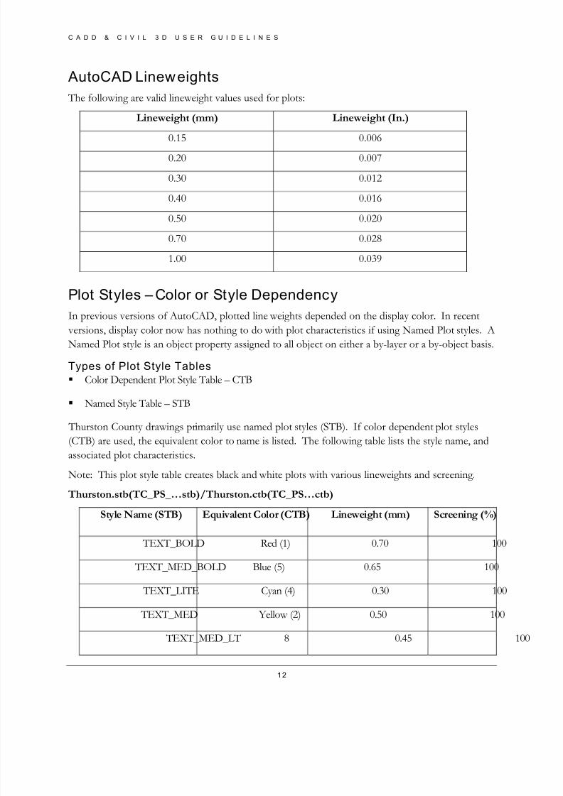
AutoCAD Lineweights
The following are valid lineweight values used for plots:
Lineweight (mm) Lineweight (In.)
0.15 0.006
0.20 0.007
0.30 0.012
0.40 0.016
0.50 0.020
0.70 0.028
1.00 0.039
Plot Styles – Color or Style Dependency
In previous versions of AutoCAD, plotted line weights depended on the display color. In recent
versions, display color now has nothing to do with plot characteristics if using Named Plot styles. A
Named Plot style is an object property assigned to all object on either a by-layer or a by-object basis.
Types of Plot Style Tables
Color Dependent Plot Style Table – CTB
Named Style Table – STB
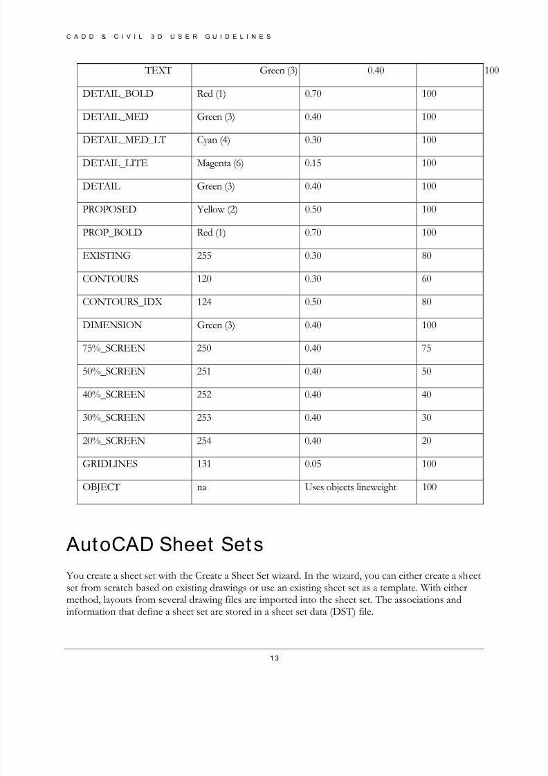
Thurston County drawings primarily use named plot styles (STB). If color dependent plot styles
(CTB) are used, the equivalent color to name is listed. The following table lists the style name, and
associated plot characteristics.
Note: This plot style table creates black and white plots with various lineweights and screening.
Thurston.stb(TC_PS_…stb)/Thurston.ctb(TC_PS…ctb)
Style Name (STB) Equivalent Color (CTB) Lineweight (mm) Screening (%)
TEXT_BOLD Red (1) 0.70 100
TEXT_MED_BOLD Blue (5) 0.65 100
TEXT_LITE Cyan (4) 0.30 100
TEXT_MED Yellow (2) 0.50 100
TEXT_MED_LT 8 0.45 100
8/8/2019 Tcpw Cadd Manual 03-01-10
http://slidepdf.com/reader/full/tcpw-cadd-manual-03-01-10 13/73
C A D D & C I V I L 3 D U S E R G U I D E L I N E S
13
TEXT Green (3) 0.40 100
DETAIL_BOLD Red (1) 0.70 100
DETAIL_MED Green (3) 0.40 100
DETAIL_MED_LT Cyan (4) 0.30 100
DETAIL_LITE Magenta (6) 0.15 100
DETAIL Green (3) 0.40 100
PROPOSED Yellow (2) 0.50 100
PROP_BOLD Red (1) 0.70 100
EXISTING 255 0.30 80
CONTOURS 120 0.30 60
CONTOURS_IDX 124 0.50 80
DIMENSION Green (3) 0.40 100
75%_SCREEN 250 0.40 75
50%_SCREEN 251 0.40 50
40%_SCREEN 252 0.40 40
30%_SCREEN 253 0.40 30
20%_SCREEN 254 0.40 20
GRIDLINES 131 0.05 100
OBJECT na Uses objects lineweight 100
AutoCAD Sheet Sets You create a sheet set with the Create a Sheet Set wizard. In the wizard, you can either create a sheetset from scratch based on existing drawings or use an existing sheet set as a template. With eithermethod, layouts from several drawing files are imported into the sheet set. The associations andinformation that define a sheet set are stored in a sheet set data (DST) file.
8/8/2019 Tcpw Cadd Manual 03-01-10
http://slidepdf.com/reader/full/tcpw-cadd-manual-03-01-10 14/73
C A D D & C I V I L 3 D U S E R G U I D E L I N E S
14
Note: The sheet set data file should be stored in a network location that is accessible to all sheet setusers on the network.
To create a sheet set, you should perform the following steps:
• Consolidate drawing files. It is recommended that you move the drawing files to be used inthe sheet set into a small number of folders. This will simplify sheet set administration.
• Eliminate multiple layout tabs. It is recommended that each drawing you plan to use in thesheet set have only one layout to be used as a sheet in the sheet set. This is important foraccess to sheets by multiple users. Only one sheet in each drawing can be open at a time.
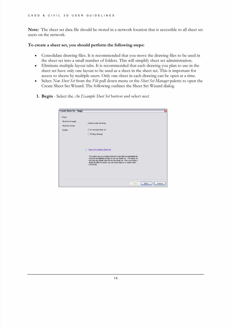
• Select New Sheet Set from the File pull down menu or the Sheet Set Manager palette to open theCreate Sheet Set Wizard. The following outlines the Sheet Set Wizard dialog.
1. Begin - Select the An Example Sheet Set button and select next .

8/8/2019 Tcpw Cadd Manual 03-01-10
http://slidepdf.com/reader/full/tcpw-cadd-manual-03-01-10 15/73
C A D D & C I V I L 3 D U S E R G U I D E L I N E S
15
2. Sheet Set Example – Select TC_Sheet_Set from the example list or if not listed Select theBrowse to another sheet set to use as an example button and browse to the Thurston Co. sheet settemplate located at \DESIGN\Engineering\CAD_Files\Sheet_Sets\ TC_Sheet_Set.dst
3. Sheet Set Details - Name the sheet set using the CRP No. and the project name. Enter adescription if applicable. In the Store sheet set data file (dst.) here: box enter or browse to theCRP file for the project and find the AutoCAD Sheet Set folder. Select Next .
8/8/2019 Tcpw Cadd Manual 03-01-10
http://slidepdf.com/reader/full/tcpw-cadd-manual-03-01-10 16/73
C A D D & C I V I L 3 D U S E R G U I D E L I N E S
16
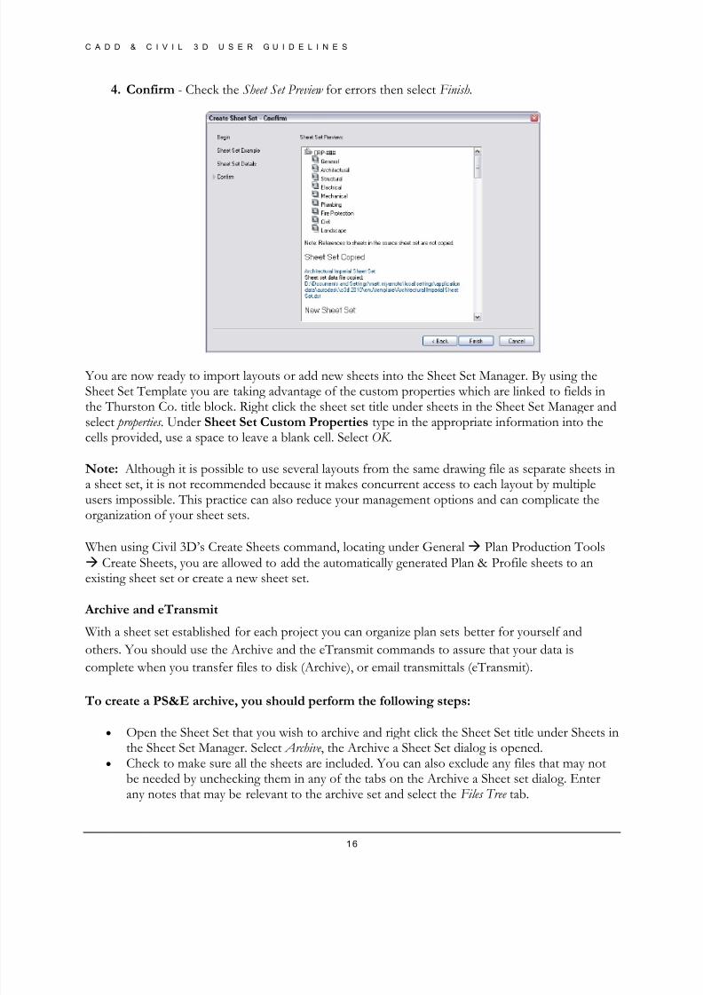
4. Confirm - Check the Sheet Set Preview for errors then select Finish.
You are now ready to import layouts or add new sheets into the Sheet Set Manager. By using theSheet Set Template you are taking advantage of the custom properties which are linked to fields inthe Thurston Co. title block. Right click the sheet set title under sheets in the Sheet Set Manager andselect properties . Under Sheet Set Custom Properties type in the appropriate information into thecells provided, use a space to leave a blank cell. Select OK .
Note: Although it is possible to use several layouts from the same drawing file as separate sheets ina sheet set, it is not recommended because it makes concurrent access to each layout by multipleusers impossible. This practice can also reduce your management options and can complicate theorganization of your sheet sets.
When using Civil 3D’s Create Sheets command, locating under General Plan Production Tools Create Sheets, you are allowed to add the automatically generated Plan & Profile sheets to anexisting sheet set or create a new sheet set.
Archive and eTransmit
With a sheet set established for each project you can organize plan sets better for yourself and
others. You should use the Archive and the eTransmit commands to assure that your data is
complete when you transfer files to disk (Archive), or email transmittals (eTransmit).
To create a PS&E archive, you should perform the following steps:
• Open the Sheet Set that you wish to archive and right click the Sheet Set title under Sheets inthe Sheet Set Manager. Select Archive , the Archive a Sheet Set dialog is opened.
• Check to make sure all the sheets are included. You can also exclude any files that may notbe needed by unchecking them in any of the tabs on the Archive a Sheet set dialog. Enterany notes that may be relevant to the archive set and select the Files Tree tab.
8/8/2019 Tcpw Cadd Manual 03-01-10
http://slidepdf.com/reader/full/tcpw-cadd-manual-03-01-10 17/73
C A D D & C I V I L 3 D U S E R G U I D E L I N E S
17
• Select the Add File button and add any relevant files to the archive set (engineer estimates,specification documents, etc.) these should show on the files tree as user added files.
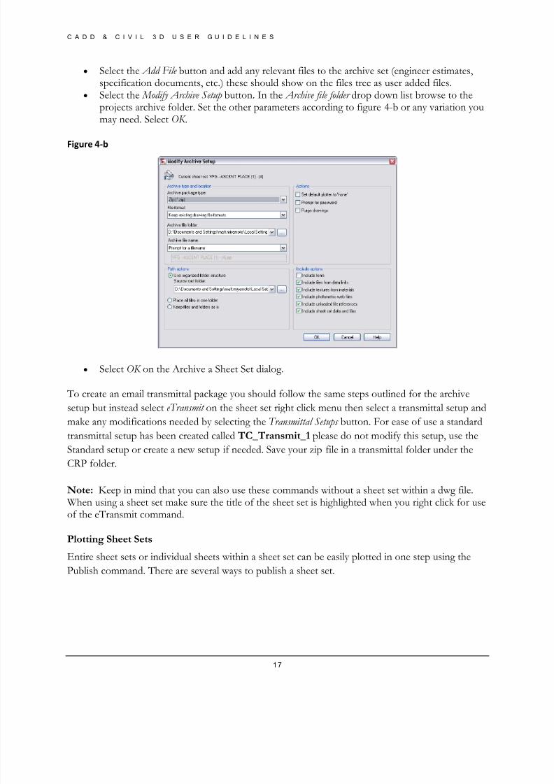
• Select the Modify Archive Setup button. In the Archive file folder drop down list browse to theprojects archive folder. Set the other parameters according to figure 4-b or any variation youmay need. Select OK .
Figure 4‐b
• Select OK on the Archive a Sheet Set dialog.
To create an email transmittal package you should follow the same steps outlined for the archive
setup but instead select eTransmit on the sheet set right click menu then select a transmittal setup andmake any modifications needed by selecting the Transmittal Setups button. For ease of use a standard
transmittal setup has been created called TC_Transmit_1 please do not modify this setup, use the
Standard setup or create a new setup if needed. Save your zip file in a transmittal folder under the
CRP folder.
Note: Keep in mind that you can also use these commands without a sheet set within a dwg file. When using a sheet set make sure the title of the sheet set is highlighted when you right click for useof the eTransmit command.
Plotting Sheet Sets
Entire sheet sets or individual sheets within a sheet set can be easily plotted in one step using the
Publish command. There are several ways to publish a sheet set.
8/8/2019 Tcpw Cadd Manual 03-01-10
http://slidepdf.com/reader/full/tcpw-cadd-manual-03-01-10 18/73
C A D D & C I V I L 3 D U S E R G U I D E L I N E S
18
To publish a sheet set using the page set-ups for each individual drawing:
• Open the Sheet Set that you wish to publish and right click the Sheet Set title. Select Publish>Publish to plotter , AutoCAD plots all the sheets in the sheet set according to the specificationsof each individual drawing’s page set-up.
To publish a sheet set as a PDF:
• Open the Sheet Set that you wish to publish and right click the Sheet Set title. SelectPublish> Publish to PDF . Drawings will be plotted in PDF format according to thespecifications of each individual drawing’s page setup.
To publish a sheet set as a DWF or DWFx:
• Open the Sheet Set that you wish to publish and right click the Sheet Set title. SelectPublish> Publish to DWF(x). Drawings will be plotted in DWF or DWFx format according tothe specifications of each individual drawing’s page setup.
To publish a sheet set with different Page Setups:
• Open the Sheet Set that you wish to publish and right click the Sheet Set title. SelectPublish> Manage Page Setup
8/8/2019 Tcpw Cadd Manual 03-01-10
http://slidepdf.com/reader/full/tcpw-cadd-manual-03-01-10 19/73
C A D D & C I V I L 3 D U S E R G U I D E L I N E S
19
Chapter
2Project Startup
This document outlines the Thurston County Design & Construction Project StartupProcess for Setting the Default Template File path.
When beginning a new Civil 3D project, it is always best practice to start with your own
organizations Civil 3D Drawing Template. Template files (.dwt) contain pre-determined layers,
styles, and settings that streamline project creation process, and reduce time spent on creating these
items from scratch.
Thurston County Public Works Department’s Civil 3D Drawing Template is called
TC_PD_C3D.dwt and is located in O:\DESIGN\Engineering\CAD_Files\ACAD
Defaults\Templates
To save additional time, this template can be set as the default template for the QNEW command in
Civil 3D which creates a new blank drawing file based on a specified Template.
Sett ing TC_PD_C3D.dwt File as the Default Template
1. Launch Civil 3D
2. With a blank drawing open, enter OP at the command line to launch the Options
dialog
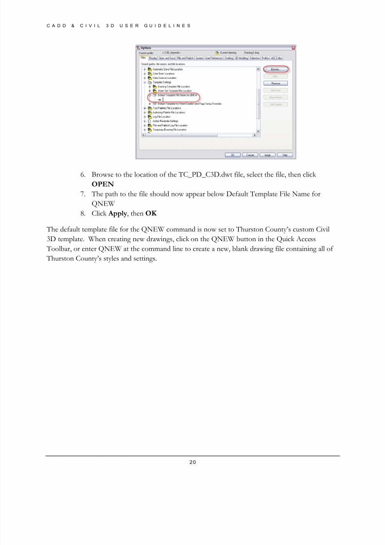
3. In the FILES tab of the Options dialog, expand (click on “+”) Template Settings
4. Expand Default Template File Name for QNEW
5. Under Default Template File Name for QNEW, click BROWSE to select the
TC_PD_C3D.dwt file
8/8/2019 Tcpw Cadd Manual 03-01-10
http://slidepdf.com/reader/full/tcpw-cadd-manual-03-01-10 20/73
C A D D & C I V I L 3 D U S E R G U I D E L I N E S
20
6. Browse to the location of the TC_PD_C3D.dwt file, select the file, then click
OPEN
7. The path to the file should now appear below Default Template File Name for
QNEW
8. Click Apply, then OK
The default template file for the QNEW command is now set to Thurston County’s custom Civil
3D template. When creating new drawings, click on the QNEW button in the Quick Access
Toolbar, or enter QNEW at the command line to create a new, blank drawing file containing all of
Thurston County’s styles and settings.
8/8/2019 Tcpw Cadd Manual 03-01-10
http://slidepdf.com/reader/full/tcpw-cadd-manual-03-01-10 21/73
C A D D & C I V I L 3 D U S E R G U I D E L I N E S
21
Chapter
3Creat ing Pro jec t Draw ing (.dw g) Fi les
This document outlines the Thurston County Design & Construction Drawing File creation process for New Project Drawing files
When beginning a project, there are three common scenarios that design teams typically encounter.
The following Best Practices outline the recommended steps for:
1. Incorporating a Civil 3D drawing Based on your Template
2. Incorporating a Civil 3D drawing that was created using a different template
3. Incorporating Non-AutoCAD drawings
Draw ings Based on Your Templa t e
In situations where a project is managed from start to finish within your organization, drawing files
will most likely be created using your custom Civil 3D template. An example of this situation is
where a surveyor has collected data and created a topographic survey drawing using the propertemplate file as the starting point, or where an existing drawing has already been created by another
engineer at your organization. This is the most ideal situation, and requires little to no adjustments
to the provided drawing file.
When provided with this type of file, simply open the drawing using Civil 3D, and you can begin
work on the project. As a Best Practice, run the –PURGE and AUDIT commands to remove
unnecessary files and fix possible errors when working on a drawing for the first time.
Inc orporat ing Civ i l 3D Draw ings Creat ed us ing a
Di f fe ren t Templa te
This is one of the most common situations encountered when working with a consultant or outside
provider. In this case, you have a Civil 3D drawing file, however it was created using styles and
settings that do not match your custom template. To resolve this issue, you can simply drag and
drop styles from your custom template file into the provided drawing.

8/8/2019 Tcpw Cadd Manual 03-01-10
http://slidepdf.com/reader/full/tcpw-cadd-manual-03-01-10 22/73
C A D D & C I V I L 3 D U S E R G U I D E L I N E S
22
To incorporate your custom styles and settings into another drawing, open the provided file and
your custom template side by side. In the window for your custom template, switch to the
SETTINGS tab in the Toolspace, and drag your desired styles into the project drawing. If the
provided drawing file contains styles with the same name, you will be prompted to overwrite or
ignore the copied file. Once you have dragged and dropped the proper styles from your drawing
template into the provided drawing file, they will appear in the Settings tab of the provided drawing and you will have access to them when working with Civil 3D objects.
Once again, the –PURGE and AUDIT commands should be run after the styles are copied to fix
errors and purge unnecessary files.
Inc orpora t ing Non-Aut oCAD or Non-Civi l 3D Draw ings
The third common scenario is when a non-AutoCAD or non-Civil 3D drawing or information is
provided. In this case, you will be incorporating the provided data into an existing or new drawing
created using your custom template.
Non-AutoCAD Drawings
When working with drawings created using other types of software, begin by starting a new drawing
file based on your custom template. With the blank drawing open, use the INSERT command to
insert the provided file into the blank drawing. The insert command will work with AutoCAD .dwg
files, Eagle Point .dwg files, and .DXF files. If Microstation .dgn files or other software application
files are provided, use FILEIMPORT IMPORT FROM OTHER FORMATS. The
available file formats are: WMF, SAT, DGN, and 3DS.
Import ing Design Data
The INSERT and IMPORT commands will work for importing linework and shapes into your new
Civil 3D drawing. Additional object data from Eagle Point Projects and LandXML files can also be
imported. When moving from Eagle Point to Civil 3D, rather than losing legacy project
information, you can use LandXML Files to import design data from an Eagle Point project into
Civil 3D. LandXML files can be generated from Eagle Point and imported into Civil 3D to transfer
design information from one program to another.
For Land XML Files, use FILEIMPORT IMPORT LANDXML (after the Land XML File
has been created through Eagle Point). Select the Land XML file you wish to import, then click OPEN.
Tr iangulat ed I r regular Netw ork (TIN) L ines
When working with previously created ground models, drawing files may be provided that contain a
Triangulated Irregular Network (TIN) View of a surface. TIN lines are 3D line segments whose

8/8/2019 Tcpw Cadd Manual 03-01-10
http://slidepdf.com/reader/full/tcpw-cadd-manual-03-01-10 23/73
C A D D & C I V I L 3 D U S E R G U I D E L I N E S
23
endpoint vertices connect two known point on a ground model. When TIN lines are provided in a
drawing file, they should be added directly to a Surface’s Definition collection as Breaklines.
If 3D Faces are provided, they should be added to the surface definition through the Drawing
Objects item.
Points
If a point file is provided, those points can be imported directly into Civil 3D to create Point
Objects using the Points Import/Export Points Import Points command. Civil 3D will
read the point file, and use the information to automatically create points in the drawing. New
points will be added to the All Points point group, and can be further organized once created.
As with the previous methods, it is recommended that the –PURGE and AUDIT commands are
run on the file after inserting and importing files.

8/8/2019 Tcpw Cadd Manual 03-01-10
http://slidepdf.com/reader/full/tcpw-cadd-manual-03-01-10 24/73
C A D D & C I V I L 3 D U S E R G U I D E L I N E S
24
Chapter
4Creat ing Topographic Survey
Drawings
This document outlines the Thurston County Design & Construction Process for Creating New Topographic Survey Drawings
Surveyors are typically the first designers to work on project drawings. They are responsible for
adding and creating the objects and information for the existing features on a project site. Surveyors
are also responsible for creating the Existing Ground model which the Civil Design Engineer will
use as the basis of their design.
St ar t ing a New Draw ing
Surveyors and Survey drafters should begin to create topographic drawings in Civil 3D by starting a
blank file using the TC_PD_C3D.dwt file.
Begin by launching Civil 3D 2010. If the TC_PD_C3D.dwt file is set as the Default Template File
for QNEW, the blank drawing that appears will be based on the custom template. If it is not set as
the default, use FILENEW to open the Select Template dialog, and select the
TC_PD_C3D.dwt file.
To set the TC_PD_C3D.dwt file as the default, refer to Setting TC_PD_C3D.dwt File As the
Default Template in the Project Startup file.
The drawing file created from the TC_PD_C3D.dwt file contains the proper Point Styles, Point
Label Styles, and Description Key Set for importing Survey information.
8/8/2019 Tcpw Cadd Manual 03-01-10
http://slidepdf.com/reader/full/tcpw-cadd-manual-03-01-10 25/73
C A D D & C I V I L 3 D U S E R G U I D E L I N E S
25
Surfac e Model ing Proc ess
As a Best Practice, there are four steps to creating a Civil 3D surface model. Following these steps
will help reduce errors that may be encountered in the modeling process.
1. Assemble Data
In this step, surveyors should organize and assemble the different types of data they have for
the project. Organizing and assembling data will help streamline the process of adding data
to a surface definition. Points, Point Groups, and Contours should be created, imported and
organized.
2. Add Data to the Surface Definition
Once your data has been assembled, assign data to your surfaces Definition collection by
right-clicking on the proper heading and selecting Add…
3. Evaluate your Surface
Once data has been added to a surface’s Definition, a Civil 3D Surface object is
automatically generated. As a Best Practice, users should evaluate the surface by inspecting
triangulation, and using 3D Views or Object Viewer to check for erroneous points and spot
elevations that may exist.
4. Add More Data, Modify Data, Apply Surface Edits
After evaluating the surface model, fix any errors or make adjustments by adding more data
(Breaklines & Boundaries), modifying the data (Add/Delete lines and points), and apply surface edits (Raise/Lower Surface for datum adjustment, Simplify Surface for Point
Removal and Edge Contraction)
Saving Your Draw ing
Save this drawing as: <CRP#_SV_MM_DD_YY.dwg>
For more information pertaining to standard file naming conventions, refer to Chapter 1 - CADD
& Civil 3D User Guidelines.
8/8/2019 Tcpw Cadd Manual 03-01-10
http://slidepdf.com/reader/full/tcpw-cadd-manual-03-01-10 26/73
C A D D & C I V I L 3 D U S E R G U I D E L I N E S
26
Chapter
5Creat ing t he Ex is t ing Ground Sur fac e
This document outlines the Thurston County Design & Construction Process for Creating the Existing Ground Surface Model
Once points and other survey information have been added and organized in the drawing file, the
next step for the Surveyor is to create the Existing Ground Surface Model. The surface model isgenerated based on different types of data that is added to its Definition collection.
The following steps outline the Best Practices for creating and adding data to a Civil 3D Exiting
Ground Surface model.
Creat ing t he Ex is t ing Ground Sur fac e
1. In the Prospector tab of the Toolspace, right-click SURFACES and select CREATE
SURFACE
2. In the Create Surface dialog box, enter a name (i.e. Existing Ground). The Style E – Contours 2’ and 10’ is set as default by the template file. Accept the default setting for
Render Material and click OK
3. A “+” sign now appears next the Surfaces collection in the Prospector tab, notifying you
that a Surface has been created in the drawing.
Adding Dat a to t he Sur fac e Def in i t ion
1. In the Prospector tab, expand (click on “+”) the Surfaces collection. The surface you
created (Existing Ground) should appear below.
2. Expand Existing Ground, then expand the Definition collection.3. To add data to the Surface definition, right-click on the proper heading (i.e. Point Groups,
Point Files, Contours) and select Add…
8/8/2019 Tcpw Cadd Manual 03-01-10
http://slidepdf.com/reader/full/tcpw-cadd-manual-03-01-10 27/73
C A D D & C I V I L 3 D U S E R G U I D E L I N E S
27
Best Prac t ic es fo r Add ing Data t o a Sur face
Def in i t ion
When adding data to a Surface’s definition collection, it is always best to add them in the order that
promotes proper modeling. It is recommended that Data should be added as follows:
1. Point Groups & Point Files
2. Contours
3. Breaklines
4. Drawing Objects & DEM Files
5. Edits
6. Boundaries *
NOTE: Not all types of data are included for every surface. Typical surfaces are created using
Point Groups or Point Files, Contours, Breaklines and Boundaries. The recommended orderreflects a situation where all types of data have been provided.
*In the case of Boundaries, Civil 3D now includes a new Data Clip Boundary type that should
be added BEFORE all other data (prior to Point Groups & Point Files).
Creat ing the Exis t ing Ground Dat a Shor t c ut
Once the Existing Ground surface has been created in the Topo drawing, a Data Shortcut should be
created to allow designers to access the Surface data without being able to make adjustments to the
surface.
For instructions on creating a Data Shortcut to the Existing Ground surface, refer to the Creating the
Data Shortcut section of Appendix D - Data Shortcuts Workflow .

8/8/2019 Tcpw Cadd Manual 03-01-10
http://slidepdf.com/reader/full/tcpw-cadd-manual-03-01-10 28/73
C A D D & C I V I L 3 D U S E R G U I D E L I N E S
28
Chapter
6Creat ing Civ i l Design Draw ings
This document outlines the Thurston County Design & Construction Process for creating New Civil Design project drawings.
With the topographic survey drawing, and Existing Ground model, design engineers can begin
working on their design. The first step to generating a Civil Design drawing is to create a new drawing file, and create a data reference to add the Existing Ground surface information to the
drawing.
St ar t ing a New Draw ing
Designers should begin with a new Civil 3D drawing that was created using the TC_PD_C3D.dwt
file.
Begin by launching Civil 3D. If the TC_PD_C3D.dwt file is set as the Default Template File for
QNEW, the blank drawing that appears will be based on the custom template. If it is not set as thedefault, use FILENEW to open the Select Template dialog, and select the TC_PD_C3D.dwt
file.
To set the TC_PD_C3D.dwt file as the default, refer to Setting TC_PD_C3D.dwt File As the
Default Template in the Chapter 2 - Project Startup file.
The drawing file created from the TC_PD_C3D.dwt file contains the proper Styles and Settings for
streamlining the creation of Roadway Alignments, Profiles, and Cross Sections.
Save this drawing as: CRP#_CD_MM_DD_YY.dwg>
For more information pertaining to standard file naming conventions, refer to Chapter 1 - CAD &
Civil 3D User Guidelines.
8/8/2019 Tcpw Cadd Manual 03-01-10
http://slidepdf.com/reader/full/tcpw-cadd-manual-03-01-10 29/73
C A D D & C I V I L 3 D U S E R G U I D E L I N E S
29
Creat ing t he Ex is t ing Ground Sur fac e Referenc e
When working in large scale projects, Data Shortcuts can be incorporated to reduce file size and
improve organization of drawing objects. Provided that a topographic survey drawing and Existing
Ground model have been generated for the project by your surveyor, a Data Reference to the
surface must be created to provide access to the surface data.
For instructions on Creating Data Shortcut References, refer to Appendix D - Data Shortcuts
Workflow . The new drawing you created using the TPCW-Custom.dwt file in the section above is
referred to as the Consumer Drawing in the document.
NOTE: For smaller scale projects, Data Shortcuts may not be necessary.
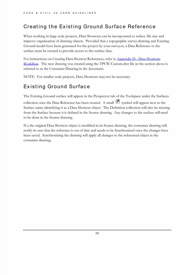
Ex is t ing Ground Sur fac e
The Existing Ground surface will appear in the Prospector tab of the Toolspace under the Surfaces
collection once the Data Reference has been created. A small symbol will appear next to the
Surface name identifying it as a Data Shortcut object. The Definition collection will also be missing
from the Surface because it is defined in the Source drawing. Any changes to the surface will need
to be done in the Source drawing.
If a the original Data Shortcut object is modified in its Source drawing, the consumer drawing will
notify its user that the reference is out of date and needs to be Synchronized once the changes have
been saved. Synchronizing the drawing will apply all changes to the referenced object in the
consumer drawing.

8/8/2019 Tcpw Cadd Manual 03-01-10
http://slidepdf.com/reader/full/tcpw-cadd-manual-03-01-10 30/73
C A D D & C I V I L 3 D U S E R G U I D E L I N E S
30
Chapter
7Road Design
This document outlines the Thurston County Design & Construction Process for creating Road Design files, including Alignments, Profiles, and Profile Views.
After the Civil Design drawing has been saved, and a Data Reference to the Existing Ground
surface has been created, designers can begin the task of Roadway Design.
Civil 3D roads consist of an Alignment, Profile, and Assembly. The alignment and profile represent
the horizontal and vertical layout of the road’s path, and the assembly is a representation of the
road’s typical cross section. When put together, the alignment, profile, and assembly create a 3D
representation of the roadway called a Corridor. These objects can all be used to generate Plan &
Profile Views, as well as Cross Section Views.
Al ignments
Alignments represent he horizontal geometry of a defined path. In terms of roadway alignments,there are two common tools used for creating alignments in Civil 3D. Create Alignment from
Polyline, and Create Alignment by Layout.
Al ignment S ty les
The appearance of an alignment in the drawing is controlled by the alignments Object Style. The
TCPW-Custom.stb file contains the default TC – Road Centerline style that is automatically
assigned to alignments created using both commands.
Al ignment Labe l Se ts
Alignment labels, which include stationing and geometry points are applied to the alignment
automatically as it is created. The labels that appear are determined by the Alignment Label Set.
The TC_PD_C3D.dwt file includes the default TC-Roadway Major Station & Geometry Points
Label Set, which automatically adds labels at 100-foot station increments and horizontal geometry
points.

8/8/2019 Tcpw Cadd Manual 03-01-10
http://slidepdf.com/reader/full/tcpw-cadd-manual-03-01-10 31/73
C A D D & C I V I L 3 D U S E R G U I D E L I N E S
31
Creat e Al ignment s f rom Poly l ine (Ribbon In ter fac e:
Crea te A l ignment f rom Objec t s )
The Create Alignments form Objects command is located in the pull-down menus under
AlignmentCreate Alignment from Polyline.
Although the pull-down command refers to a polyline, in Civil 3D, designers are also allowed to
select lines, arcs, and XREF objects to create alignments. These objects must share common
vertices in order to create a continuous alignment. Any gaps between segments should be resolved
before starting the command.
Creat e Al ignment by Layout (Ribbon In ter fac e:
A l ignment Crea t ion Too ls )
The Create Alignments form Objects command is located in the pull-down menus under
AlignmentCreate Alignment by Layout.
Activating the Create Alignment by Layout command will launch the Create Alignment – Layout
dialog box where you will be prompted to enter an alignment Name, Site, and Design Criteria. By
default, the TC-Road Centerline object style, and TC-Roadway Major Stations & Geometry
Points label set will be assigned when using this command.
Once you have specified the information in the dialog box, the Alignment Layout Toolbar will
appear on screen for your use in creating a new roadway alignment.
Prof i les
Profiles represent the vertical geometry of the roadway. Typical road designs include two profiles;
one representing the elevations along the Existing Ground Surface, and the other representing the
proposed road’s vertical geometry.
Civil 3D includes two commands for creating these profiles. Create Profile from Surface, and
Create Profile by Layout.
Creat e Prof i le f rom Surfac e
The Create Profile from Surface command is found under ProfilesCreate Profile from Surface
in the Profile pull-down menu.
Activating the Create Profile from Surface command launches the Create Profile from Surface
dialog box. In the dialog box, you will specify the Alignment, and Surface that you wish to sample
for the creation of the surface profile. Once the proper alignment has been selected and surface has
8/8/2019 Tcpw Cadd Manual 03-01-10
http://slidepdf.com/reader/full/tcpw-cadd-manual-03-01-10 32/73
C A D D & C I V I L 3 D U S E R G U I D E L I N E S
32
been added, the name will appear in the Profiles List. The default style E-Ground Profile is
automatically assigned by the template for the profile display, and the No Labels label set is also
applied.
Creat e Prof i le V iew s (Ex is t ing Ground Prof i les)
Once a profile has been created, a Profile View can be generated to graphically display the Profile
Information. When using the Create Profile from Surface command, the option to Draw in Profile
View appears in the Create Profile from Surface Dialog box. Selecting Draw in Profile View
launches the Create Profile View dialog box, which allows you to select the alignment and enter a
Profile View Name. The Profile View Style is set to TC-Profile View by the template file. You are
also allowed to specify a Station Range, and Profile View Height. The profile styles and band set
have are also set by the template file.
Creat e Prof i le by Layout
With an existing ground profile and profile view created, you can create your Finished Grade profile
using the Profile Layout Tools. Access the tools by selecting ProfilesCreate Profile by Layout
from the Profiles pull-down menu, and selecting the Profile View (by left-clicking on the grid). The
Create Profile – Draw New dialog box appears, and is where you can provide a Name, and specify
Design Criteria. The Profile Style and Label Sets are set by the template.
Adjust ing Band Dat a
When a Profile View is created using the Draw in Profile View option, the Band information only
displays Existing Ground elevations because the Finished Grade Profile does not yet exist. After
using the Profile Layout Tools, the Band information can be reset to show both Existing and
Finished Grade elevations.
To add the Finished Grade Elevations, select the Profile View (left-click on the grid), and select
Profile View Properties. In the Profile View Properties dialog box, switch to the Bands tab. In
the List of Bands box, scroll to the right until you are able to see the Profile1 and Profile2 columns.
By default Civil 3D assigns the Existing Ground Profile as Profile 1. Left-click in the cell below the
Profile2 heading to select the Finished Grade Profile you created using the Profile Layout Tools.
Once the profile has been selected, click Apply and OK to exit and update the Bands.
Creat ing Data Shor tc u ts to the A l ignment and Pro f i le
In order to reduce file size for larger scale projects, Data Shortcuts can once again be incorporated.
Alignments and Profiles can be shared through the use of Data Shortcuts by following the same
process involved in creating Data Shortcuts for the Existing Ground surface.

8/8/2019 Tcpw Cadd Manual 03-01-10
http://slidepdf.com/reader/full/tcpw-cadd-manual-03-01-10 33/73
C A D D & C I V I L 3 D U S E R G U I D E L I N E S
33
Profiles are associated and grouped under the Alignments collection in Civil 3D, so selecting a
Profile from the list of objects will automatically select its parent alignment. Selecting only the
alignment will allow you to share alignment information without sharing profile information.
For instructions on creating Data Shortcuts, refer to Appendix D - Data Shortcuts Workflow .
NOTE: Profile Views are NOT shared through Data Shortcuts. Only the data and information
used in creating the profile views are shared. If you wish to see your shared profile in a Profile View
in the new consumer drawing, you must re-create the Profile View using the Profiles Create
Profile View command under the Profiles pull-down menu.
8/8/2019 Tcpw Cadd Manual 03-01-10
http://slidepdf.com/reader/full/tcpw-cadd-manual-03-01-10 34/73
C A D D & C I V I L 3 D U S E R G U I D E L I N E S
34
Chapter
8Cross Sec t ions & Cross Sec t ion V iew s
This document outlines the Thurston County Design & Construction Process for Creating Sample Lines, Computing Earthwork and Material Volumes, Generating Volume Tables, Creating Cross Sections & Cross Section Views.
Generating Cross Sections and Cross section views can be done once the alignment, profile, andcorridor model have been created in Civil 3D. Roadway cross sections in Civil 3D are generated
along Sample Line Groups, which are used to determine the station and swath width for each of the
sections.
After the Alignment and Profile have been defined, an Assembly must be created and applied in
order to produce a corridor model. You can have any number of assemblies in your drawing file,
each representing a typical roadway cross section. Typical assemblies can be created ahead of time
and saved into your Toolpalettes to save drafting time on future projects.
Once a corridor model exists in the drawing, follow the steps below to generate a Sample LineGroup and generate Cross Section Views.
St ar t ing a New Draw ing
Designers should begin with a new Civil 3D drawing that was created using the TC_PD_C3D.dwt
file.
Begin by launching Civil 3D. If the TC_PD_C3D.dwt file is set as the Default Template File for
QNEW, the blank drawing that appears will be based on the custom template. If it is not set as the
default, use FILENEW to open the Select Template dialog, and select the TC_PD_C3D.dwt
file.
To set the TC_PD_C3D.dwt file as the default, refer to Setting TC_PD_C3D.dwt File As the
Default Template in the Chapter 2 - Project Startup file.
The drawing file created from the TC_PD_C3D.dwt file contains the proper Styles and Settings for
streamlining the creation of Roadway Alignments, Profiles, and Cross Sections.
8/8/2019 Tcpw Cadd Manual 03-01-10
http://slidepdf.com/reader/full/tcpw-cadd-manual-03-01-10 35/73
C A D D & C I V I L 3 D U S E R G U I D E L I N E S
35
Save this drawing as: CRP#_XS_MM_DD_YY.dwg>
For more information pertaining to standard file naming conventions, refer to Chapter 1 - CADD
& Civil 3D User Guidelines.
Creat ing the Exis t ing Ground Sur fac e, A l ignment &Prof i le Referenc es
When working in large scale projects, Data Shortcuts can be incorporated to reduce file size and
improve organization of drawing objects. Provided that the Data Shortcuts have been created for
the Existing Ground surface, Alignments, and Profiles in your project, data references can be
created to incorporate the information into your Cross Section drawing.
For instructions on Creating Data Shortcut References, refer to the Creating the Data Shortcut section
of Appendix D - Data Shortcuts Workflow . The new drawing you created using the TPCW-
Custom.dwt file in the section above is referred to as the Consumer Drawing in the document.
NOTE: For smaller scale projects involving a shorter or smaller numbers of alignments and
profiles, Data Shortcuts may not be necessary.
Sam ple L ines & Sam ple L ine Groups
Sample Lines are graphical representations for the location of each roadway cross section. Sample
Lines are assigned to Stations along an alignment, and have a user defined swath width to determine
the distance from the centerline that the section is sampled.
Creat ing Sample L ines & Sam ple L ine Groups
Begin the process of creating sample lines and a sample line group by selecting Sections Create
Sample Lines from the Sections pull-down menu.
When prompted, select the alignment on which you wish to create sample lines. In the Create
Sample Line Group dialog box, specify a Name (by default the Sample Line Group will have the
name of its parent alignment followed by a number). The styles of the Sample Lines and Labels are
pre-set by the drawing template.
In the Select Data Sources to Sample window, select all sources you want to include in your cross
section. Typically this includes the Existing Ground, Corridor, and Datum surface generated from
the corridor model. Assign the proper styles for each object in the Style column of the Select Data
Sources to Sample window.
After clicking OK , the Sample Line Toolbar will appear. Use the available tools to generate sample
lines along your alignment. Options include:
8/8/2019 Tcpw Cadd Manual 03-01-10
http://slidepdf.com/reader/full/tcpw-cadd-manual-03-01-10 36/73
C A D D & C I V I L 3 D U S E R G U I D E L I N E S
36
By Range of Stations – Allows the user to specify a station range and interval along the station
range to automatically generate a series of sample lines.
At a Station – The default setting for creating a sample line, this option allows the user to specify a
single station for creation of a single sample line.
From Corridor Stations – Allows the user to use the existing corridor frequency as the locations
for sample lines.
Pick Points on Screen – Allows the user to define points along the path of a sample line.
Select Existing Polylines – Allows the user to select an existing polyline in the drawing and use
that to create a sample line.
There is no correct value or location for generating sample lines. In general, it is best practice to
increase the frequency of sample lines along curved portions of the road to produce a better overall
representation of the roadway. The default values have been set to sample at 50-foot incrementsalong straight segments and 25-foot segments along curves. In areas with small curve radiuses, this
value may be reduced.
When the sample line creation process is complete, sample lines at the specified stations or along the
station range will appear in the drawing. These lines are set to a non-plotting layer, and should not
appear on plan sheets.
Comput ing Ear thw ork & Mater ia l Vo lumes
After a Sample Line Group has been generated for an alignment, Earthwork and Material Volume
computations can be done. Once calculations are complete, the information can be added to
drawing files quickly using the Add Tables option within the Sections pull-down menu.
To Compute Materials, select Sections Compute Materials. The Select a Sample Line Group
dialog will appear, where you must select an Alignment and Sample Line Group to compute
materials from. The alignment and sample line group must be created prior to starting the Compute
Materials command. After selecting the appropriate alignment and sample line group, click OK .
The Computer Materials dialog box will appear. Specify the Quantity Takeoff Criteria from the
drop down list at the top left, then set the appropriate objects under the Object Name column of
the dialog box. For Earthworks and Cut & Fill volumes, you must set the appropriate Existing Ground surface and Datum surface for computation. For roadway Materials, you must specify the
corridor shape that corresponds to the Material Name (Pavement, Base, Subbase, etc.) shown on
the list.
When computing earthwork and cut & fill quantities, be sure to use the Datum surface generated
from the corridor model. The Datum surface represents the bottom most geometry of a road
8/8/2019 Tcpw Cadd Manual 03-01-10
http://slidepdf.com/reader/full/tcpw-cadd-manual-03-01-10 37/73
C A D D & C I V I L 3 D U S E R G U I D E L I N E S
37
model. This surface type excludes the areas that will be replaced with future pavement, base, and
sub-base materials.
Add ing Vo lume Tab les & Repor ts
After the Compute Materials command has been completed, the information is now available withinCivil 3D to generate an Earthwork or Material Volume Table. To add a table, select Sections
Total Volume or SectionsMaterial Volume accordingly.
In the Volume Table dialog box, select the appropriate Table Style and verify the alignment and
sample line group name. Under the Split Table section, you are allowed to specify the number of
rows per table, and number of tables per stack. By default it is set to 20 rows and three (3) stacks.
The offset distance (space between tables), tile pattern and behavior are also set here.
For dynamic tables, be sure to select the Dynamic option under the Behavior Relativity Mode:
option. Dynamic tables will remain linked to their alignments and sample line groups, and willautomatically update when changes are made.
To generate a Volume Report, select Sections Generate Volume Report… In the Report
Quantities dialog box, select the Alignment, Sample Line Group, and Material List. Under the
Select a Style Sheet option, select the proper .XSL file for the material type. Verify that the
Display XML Report option is un-checked, then click OK .
A Volume Report will be generated and can be saved as an external file as needed.
Create Sec t ion V iew / Crea te Mu l t ip le Sect ion V iew s
After generating a Sample Line Group, the information within the group can be used to create Cross
Section Views. The horizontal and vertical scales of the cross section views are determined by the
drawings scale shown in the status bar on the bottom right of the screen. The template has been set
to automatically calculate vertical scale at 2x the horizontal scale (i.e. 1:10 H 1:5 V).
Once the scale has been properly set, there are two options for creating Cross Section Views.
Create Section View – Creates a single section view from a sample line that the user selects. For
this option, the plot style is defaulted to plot all.
Create Multiple Section Views – Creates multiple section views from a Sample Line group along
the entire station range, or user specified station range. The Section View Style and Group Plot
Style are set by the template file to plot by page.
8/8/2019 Tcpw Cadd Manual 03-01-10
http://slidepdf.com/reader/full/tcpw-cadd-manual-03-01-10 38/73
C A D D & C I V I L 3 D U S E R G U I D E L I N E S
38
Chapter
9Creat ing V iew Frames & Genera t ing
Sheet Set s
This document outlines the Thurston County Design & Construction Process for Creating View Frames and Generating Sheets using the Civil 3D Plan Production Tools.
With an Alignment and Profile in the drawing, the Civil 3D can automatically generate View Frames
& View Frame Groups to display the portions of the alignment that will fit on each scaled sheet.
View Frames are generated based on user defined constraints for Layout and Scale.
By Default, a 1:40 Scale, ANSI D 22x34 sheet has been set up for creation of View Frames.
Creat ing View Fram es & View Fram e Groups (Ribbon
In te r face : Annota t e Tab Create V iew Frames)
Activate the Create View Frames dialog box by entering CREATEVIEWFRAMES at the
command line.
On Page 1 of the Create View Frames dialog, select the proper Alignment and Station Range you
wish to generate View Frames for.
On Page 2, Select the Plan and Profile option as the type of sheet you want to generate, then click
the Ellipsis (…) button under the Sheet Settings section and select the TC 34x22 Plan &
Profile.dwt file.
In the View Frame Placement section, select the orientation of the View Frames. The two included
options are:
Along the Alignment – rotates the View Frames orientation to follow the path of the parent
alignment.
Rotate to North – View Frames will be automatically set to always display North at 90 degrees.
8/8/2019 Tcpw Cadd Manual 03-01-10
http://slidepdf.com/reader/full/tcpw-cadd-manual-03-01-10 39/73
C A D D & C I V I L 3 D U S E R G U I D E L I N E S
39
The option to show a buffer area at the beginning of the alignment is also on Page 2. The template
has been set to include a 50’ buffer before the start of the alignment.
NOTE: The TC 34x22 Plan & Profile.dwt file must be saved to a common location on the server,
or placed in the Plan Production subfolder of each user’s workstation. Once the file has been
mapped, its location should be saved to the template file.
A View Frame Group is automatically created for the View Frames, and is named:
VFG - <Alignment Name> - ##
If you wish to specify a different name, the option is available under the View Frame Group section
on Page 3.
Match lines have been set to snap to a 25-foot increment by default. If you wish to change the
increment, the option is available under the Positioning section of Page 4.
Accept the defaults on Page 5 for Profile View and Band Set styles, then click Create View Frames
After View Frames have been generated, they will appear as Cyan rectangles in the drawing. They
are set to a No Plot layer, and are not intended to appear on plan sheets.
Creat ing Sheets & Sheet Sets (Ribbon In ter fac e:
Creat e Sheet s)
With View Frames now in the drawing, Sheets can be generated. Activate the create sheets
command by entering CREATESHEETS at the command line.
The Create Sheets dialog will appear, with options for sheet creation.
Page 1 of the dialog allows you to select the View Frame Group for use in generating sheets. When
multiple alignments and View Frame Groups exist in the drawing, they will appear in the drop down
list under the View Frame Group Section. In this section, you may also specify whether to generate
sheets for all frames within the group or for selected frames.
In the Layout Create section, the option for generating sheets in a New Drawing or Current
Drawing are available. If selecting New Drawings, you may also specify to create one layout (sheet)
per drawing or all layouts in the same drawing. Names for the new layouts are also specified here.By default each new layout is named: Sheet - ##
Page 2 of the dialog allows users to specify a New Sheet Set or Existing Sheet set to add the created
sheets to. When creating a new sheet set, the default name will be: VFG - <Alignment Name> -
##
Accept the defaults on Pages 3 and 4 of the dialog, then click Create Sheets.

8/8/2019 Tcpw Cadd Manual 03-01-10
http://slidepdf.com/reader/full/tcpw-cadd-manual-03-01-10 40/73
C A D D & C I V I L 3 D U S E R G U I D E L I N E S
40
You will be prompted to save your file and pick a reference point for your profiles in the existing
drawing (pick a point off to the side similar to how you would normally generate a profile view).
Once the drawing has been saved and reference spot has been selected, Civil 3D will automatically
create sheets based on the specified View Frame Group and add them to a Sheet Set.
When the process is complete, new layouts will exist in the current drawing or new drawing files will
be created (based on your selection on Page 2 of the dialog).
NOTE: Annotations are not automatically generated when creating sheets. Only a layout
containing border and viewports displaying Plan and Profile views are generated. Adjustments and
additions to the viewports and layouts may be required before construction documents are printed.
8/8/2019 Tcpw Cadd Manual 03-01-10
http://slidepdf.com/reader/full/tcpw-cadd-manual-03-01-10 41/73
C A D D & C I V I L 3 D U S E R G U I D E L I N E S
41
Appendix A
Reference File Name Descriptions
SB Standard border drawing PD Prototype drawing/Default template file
XS Prototype cross-section drawing
PP Prototype plan and profile drawing
FC Field code/node definition file
LD Linetype definition file TC Thurston County designator
Project File Name Descriptions
SV Base Topo drawing
CD Civil Design drawing
AD Architectural Design drawing
XS Cross-section drawing
PP Plan and profile drawing
TF Topographical points file
SS Sheet set file
CP Current plans set
CS Current specifications set
8/8/2019 Tcpw Cadd Manual 03-01-10
http://slidepdf.com/reader/full/tcpw-cadd-manual-03-01-10 42/73
C A D D & C I V I L 3 D U S E R G U I D E L I N E S
42
Appendix B – Layer Naming
First part of the name describes discipline.
CI CIVIL DESIGN
GS GAS
OL OIL
PO POWER
RE REFERENCE
SS SANITARY SEWER
SD STORM DRAINAGE
SF SURFACE FEATURES
SV SURVEY
TL TELEPHONE
FO FIBER OPTICS
TF TRAFFIC
TV CABLE TELEVISION
WA WATER
DR DRAFTING
Second part of the name depends on discipline chosen, some of
which cross to other disciplines.
Objects under RE (layers for title blocks, match lines, etc.)
MTCH MATCH LINE
GRID PROFILE GRID
TITL TITLE BLOCK
8/8/2019 Tcpw Cadd Manual 03-01-10
http://slidepdf.com/reader/full/tcpw-cadd-manual-03-01-10 43/73
C A D D & C I V I L 3 D U S E R G U I D E L I N E S
43
Objects under SV
CNTL CENTERLINE
CONT CONTOUR
CTRL CONTROL
CITY CORPORATE LIMIT
CNTY COUNTY
DATM DATUM
DLCM DONATION LAND CLAIM
ESMT EASEMENT
LROW LIMITED ACCESS ROW
LOTN LOT NUMBER
MEAN MEANDER
NORA NORTH ARROW
PRCL PARCEL
PROP PROPERTY
QSCT QUARTER SECTION
RANG RANGE
PARK RESERVATION/PARK/FOREST
ROFW RIGHT OF WAY
SECT SECTION
16ST SIXTEENTH SECTION
SOIL SOIL BORING
STAT STATE
TWNS TOWNSHIP

8/8/2019 Tcpw Cadd Manual 03-01-10
http://slidepdf.com/reader/full/tcpw-cadd-manual-03-01-10 44/73
C A D D & C I V I L 3 D U S E R G U I D E L I N E S
44
Objects under CI
ALGN ALIGNMENT
PRFL PROFILE
PRVW PROFILE VIEW
SURF SURFACE
VRFM VIEW FRAME
XSEC CROSS SECTION
Objects under TV, GS, OL, PO, SS, SD, FO, and TL
ALIN AERIAL LINE
BLIN BURIED CONDUIT
GLIN GRAVITY LINE
PLIN PRESSURE LINEMETR METER
SERV SERVICE
STCR STRUCTURE
VALV VALVE
Objects under SF
BLDG BUILDING
BUSS BUS STOP
DTCH CREEK/DITCH
CURB CURB/SIDEWALK
PVMT EDGE PAVEMENT
EMBT EMBANKMENT
FENC FENCE
GURD GUARD RAIL
LAKE LAKE/POND
MAIL MAIL BOX
RLRD RAILROAD
WALL RETAINING WALL
RIPR RIP RAP
RIVR RIVERBANK
ROCK ROCKERY
8/8/2019 Tcpw Cadd Manual 03-01-10
http://slidepdf.com/reader/full/tcpw-cadd-manual-03-01-10 45/73
C A D D & C I V I L 3 D U S E R G U I D E L I N E S
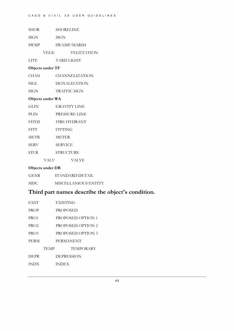
45
SHOR SHORELINE
SIGN SIGN
SWMP SWAMP/MARSH
VEGE VEGETATION
LITE YARD LIGHT
Objects under TF
CHAN CHANNELIZATION
SIGL SIGNALIZATION
SIGN TRAFFIC SIGN
Objects under WA
GLIN GRAVITY LINE
PLIN PRESSURE LINEFHYD FIRE HYDRANT
FITT FITTING
METR METER
SERV SERVICE
STCR STRUCTURE
VALV VALVE
Objects under DR
GENR STANDARD DETAIL
MISC MISCELLANIOUS ENTITY
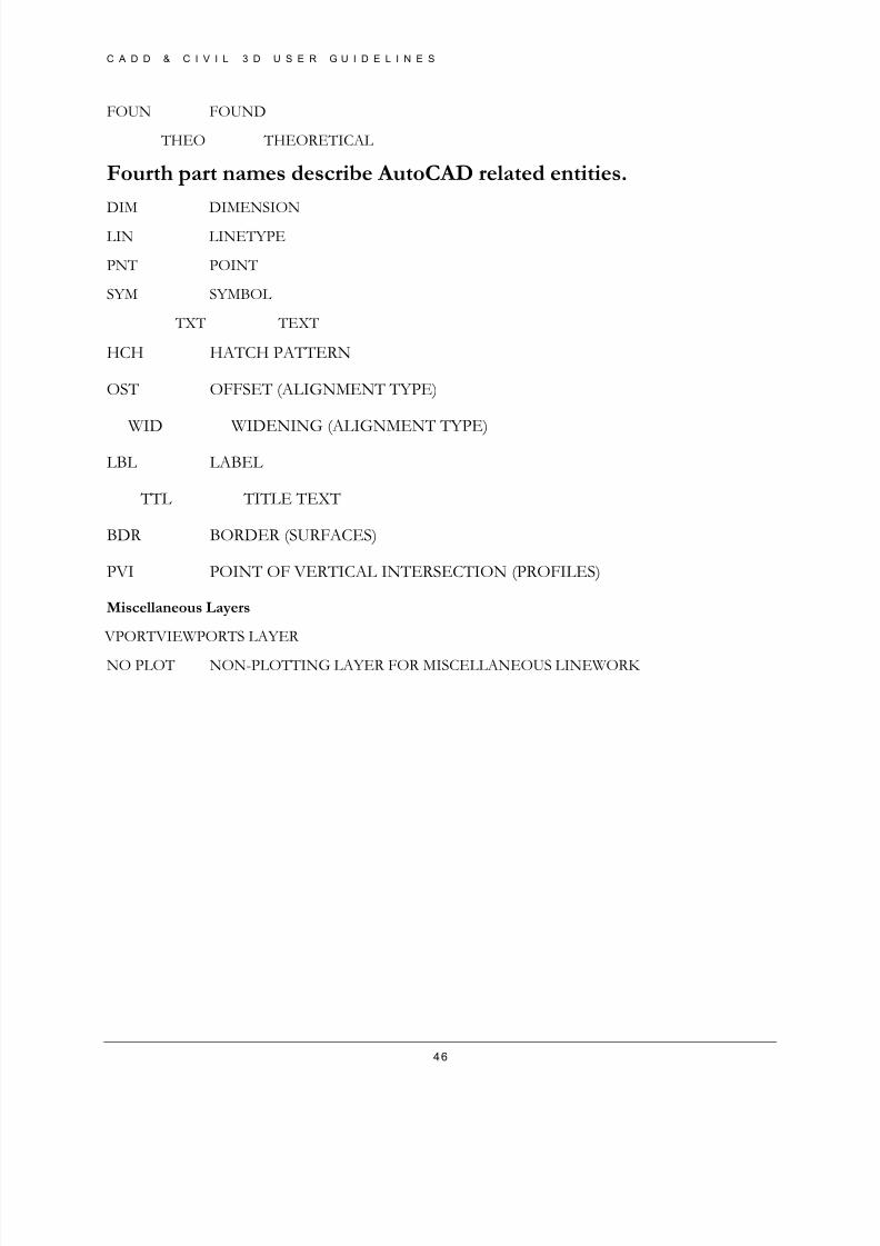
Third part names describe the object's condition.
EXST EXISTING
PROP PROPOSED
PRO1 PROPOSED OPTION 1
PRO2 PROPOSED OPTION 2
PRO3 PROPOSED OPTION 3
PERM PERMANENT
TEMP TEMPORARY
DEPR DEPRESSION
INDX INDEX
8/8/2019 Tcpw Cadd Manual 03-01-10
http://slidepdf.com/reader/full/tcpw-cadd-manual-03-01-10 46/73
8/8/2019 Tcpw Cadd Manual 03-01-10
http://slidepdf.com/reader/full/tcpw-cadd-manual-03-01-10 47/73
C A D D & C I V I L 3 D U S E R G U I D E L I N E S
47
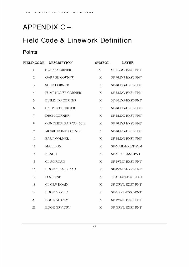
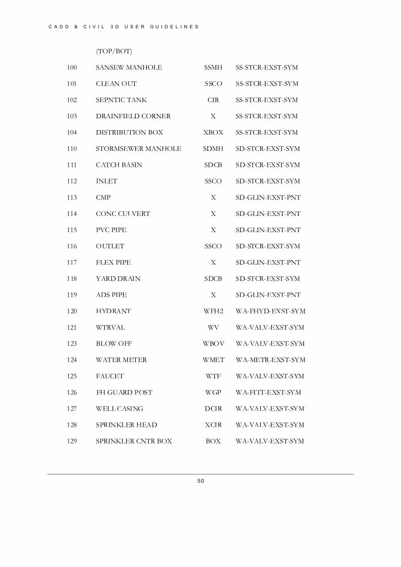
APPENDIX C –
Field Code & Linework Definit ion
Points
FIELD CODE DESCRIPTION SYMBOL LAYER
1 HOUSE CORNER X SF-BLDG-EXST-PNT
2 GARAGE CORNER X SF-BLDG-EXST-PNT
3 SHED CORNER X SF-BLDG-EXST-PNT
4 PUMP HOUSE CORNER X SF-BLDG-EXST-PNT
5 BUILDING CORNER X SF-BLDG-EXST-PNT
6 CARPORT CORNER X SF-BLDG-EXST-PNT
7 DECK CORNER X SF-BLDG-EXST-PNT
8 CONCRETE PAD CORNER X SF-BLDG-EXST-PNT
9 MOBIL HOME CORNER X SF-BLDG-EXST-PNT
10 BARN CORNER X SF-BLDG-EXST-PNT
11 MAIL BOX X SF-MAIL-EXIST-SYM
14 BENCH X SF-MISC-EXST-PNT
15 CL AC ROAD X SF-PVMT-EXST-PNT
16 EDGE OF AC ROAD X SF-PVMT-EXST-PNT
17 FOG LINE X TF-CHAN-EXST-PNT
18 CL GRV ROAD X SF-GRVL-EXST-PNT
19 EDGE GRV RD X SF-GRVL-EXST-PNT
20 EDGE AC DRV X SF-PVMT-EXST-PNT
21 EDGE GRV DRV X SF-GRVL-EXST-PNT

8/8/2019 Tcpw Cadd Manual 03-01-10
http://slidepdf.com/reader/full/tcpw-cadd-manual-03-01-10 48/73
C A D D & C I V I L 3 D U S E R G U I D E L I N E S
48
22 CL CONC ROAD X SF-PVMT-EXST-PNT
23 EDGE CONC RD X SF-PVMT-EXST-PNT
24 EDGE PARKING X SF-PVMT-EXST-PNT
25 SHOT ON PAVEMENT X SF-PVMT-EXST-PNT
27 CL RAILROAD TRACK X SF-RLRD-EXST-PNT
28 PNT ON RAIL X SF-RLRD-EXST-PNT
29 BRIDGE CORNER X SF-BRDG-EXST-PNT
30 CL BRIDGE X SF-BRDG-EXST-PNT
33 CL STRIPE X TF-CHAN-EXST-PNT
35 BACK CONC WALK X SF-PVMT-EXST-PNT
36 FACE CONC WALK X SF-PVMT-EXST-PNT
38 BACK AC WALK X SF-PVMT-EXST-PNT
39 FACE AC WALK X SF-PVMT-EXST-PNT
42 BK VERT CONC C/G X SF-CURB-EXST-PNT
43 FC VERT CONC C/G X SF-CURB-EXST-PNT
44 BK ROLLED C/G X SF-CURB-EXST-PNT
45 BK VERT CONC CURB X SF-CURB-EXST-PNT
46 FC VERT CONC CURB X SF-CURB-EXST-PNT
47 CL EXTRUDED CONC CURB X SF-CURB-EXST-PNT
48 CL EXTRUDED AC CURB X SF-CURB-EXST-PNT
49 BK AC TILT UP C X SF-CURB-EXST-PNT
50 GUTTER LINE X SF-CURB-EXST-PNT
57 CL BOTTOM SWALE X SF-DITCH-EXST-PNT
61 BOTTOM V-DITCH X SF-DITCH-EXST-PNT
62 DITCH LINE X SF-DITCH-EXST-PNT
8/8/2019 Tcpw Cadd Manual 03-01-10
http://slidepdf.com/reader/full/tcpw-cadd-manual-03-01-10 49/73
C A D D & C I V I L 3 D U S E R G U I D E L I N E S
49
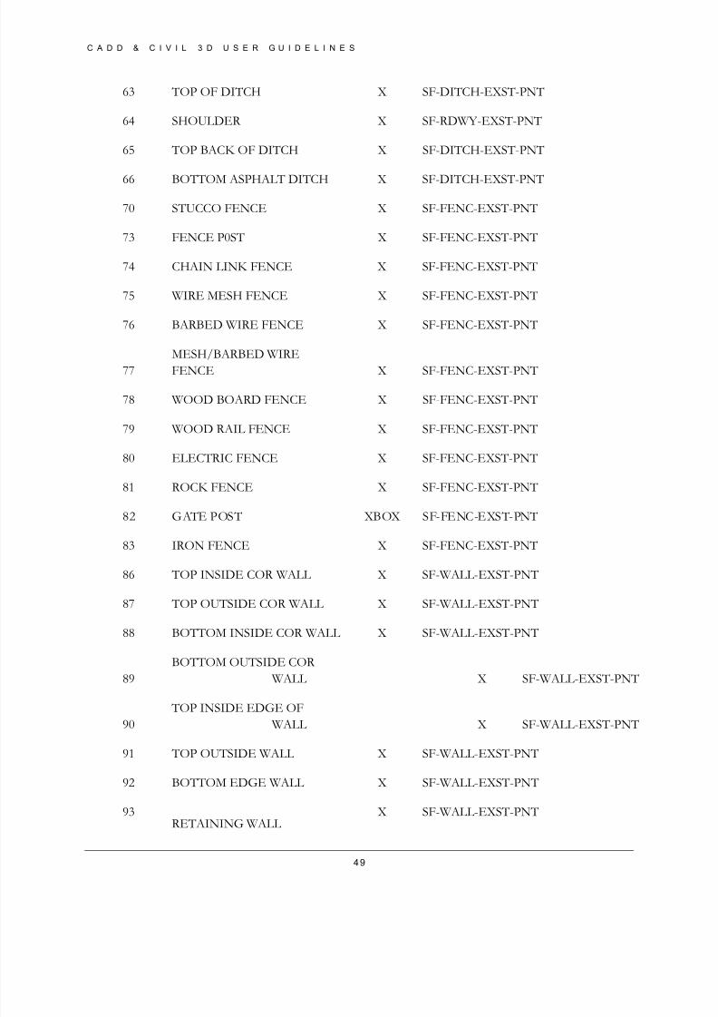
63 TOP OF DITCH X SF-DITCH-EXST-PNT
64 SHOULDER X SF-RDWY-EXST-PNT
65 TOP BACK OF DITCH X SF-DITCH-EXST-PNT
66 BOTTOM ASPHALT DITCH X SF-DITCH-EXST-PNT
70 STUCCO FENCE X SF-FENC-EXST-PNT
73 FENCE P0ST X SF-FENC-EXST-PNT
74 CHAIN LINK FENCE X SF-FENC-EXST-PNT
75 WIRE MESH FENCE X SF-FENC-EXST-PNT
76 BARBED WIRE FENCE X SF-FENC-EXST-PNT
77MESH/BARBED WIREFENCE X SF-FENC-EXST-PNT
78 WOOD BOARD FENCE X SF-FENC-EXST-PNT
79 WOOD RAIL FENCE X SF-FENC-EXST-PNT
80 ELECTRIC FENCE X SF-FENC-EXST-PNT
81 ROCK FENCE X SF-FENC-EXST-PNT
82 GATE POST XBOX SF-FENC-EXST-PNT
83 IRON FENCE X SF-FENC-EXST-PNT
86 TOP INSIDE COR WALL X SF-WALL-EXST-PNT
87 TOP OUTSIDE COR WALL X SF-WALL-EXST-PNT
88 BOTTOM INSIDE COR WALL X SF-WALL-EXST-PNT
89
BOTTOM OUTSIDE COR
WALL X SF-WALL-EXST-PNT
90 TOP INSIDE EDGE OF WALL X SF-WALL-EXST-PNT
91 TOP OUTSIDE WALL X SF-WALL-EXST-PNT
92 BOTTOM EDGE WALL X SF-WALL-EXST-PNT
93RETAINING WALL
X SF-WALL-EXST-PNT
8/8/2019 Tcpw Cadd Manual 03-01-10
http://slidepdf.com/reader/full/tcpw-cadd-manual-03-01-10 50/73
C A D D & C I V I L 3 D U S E R G U I D E L I N E S
50
(TOP/BOT)
100 SANSEW MANHOLE SSMH SS-STCR-EXST-SYM
101 CLEAN OUT SSCO SS-STCR-EXST-SYM
102 SEPNTIC TANK CIR SS-STCR-EXST-SYM
103 DRAINFIELD CORNER X SS-STCR-EXST-SYM
104 DISTRIBUTION BOX XBOX SS-STCR-EXST-SYM
110 STORMSEWER MANHOLE SDMH SD-STCR-EXST-SYM
111 CATCH BASIN SDCB SD-STCR-EXST-SYM
112 INLET SSCO SD-STCR-EXST-SYM
113 CMP X SD-GLIN-EXST-PNT
114 CONC CULVERT X SD-GLIN-EXST-PNT
115 PVC PIPE X SD-GLIN-EXST-PNT
116 OUTLET SSCO SD-STCR-EXST-SYM
117 FLEX PIPE X SD-GLIN-EXST-PNT
118 YARD DRAIN SDCB SD-STCR-EXST-SYM
119 ADS PIPE X SD-GLIN-EXST-PNT
120 HYDRANT WFH2 WA-FHYD-EXST-SYM
121 WTRVAL WV WA-VALV-EXST-SYM
123 BLOW OFF WBOV WA-VALV-EXST-SYM
124 WATER METER WMET WA-METR-EXST-SYM
125 FAUCET WTF WA-VALV-EXST-SYM
126 FH GUARD POST WGP WA-FITT-EXST-SYM
127 WELL CASING DCIR WA-VALV-EXST-SYM
128 SPRINKLER HEAD XCIR WA-VALV-EXST-SYM
129 SPRINKLER CNTR BOX BOX WA-VALV-EXST-SYM
8/8/2019 Tcpw Cadd Manual 03-01-10
http://slidepdf.com/reader/full/tcpw-cadd-manual-03-01-10 51/73
C A D D & C I V I L 3 D U S E R G U I D E L I N E S
51
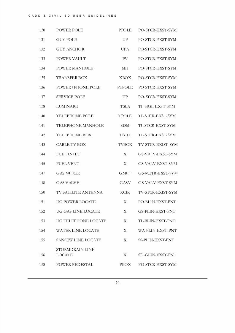
130 POWER POLE PPOLE PO-STCR-EXST-SYM
131 GUY POLE UP PO-STCR-EXST-SYM
132 GUY ANCHOR UPA PO-STCR-EXST-SYM
133 POWER VAULT PV PO-STCR-EXST-SYM
134 POWER MANHOLE MH PO-STCR-EXST-SYM
135 TRANSFER BOX XBOX PO-STCR-EXST-SYM
136 POWER+PHONE POLE PTPOLE PO-STCR-EXST-SYM
137 SERVICE POLE UP PO-STCR-EXST-SYM
138 LUMINARE TSLA TF-SIGL-EXST-SYM
140 TELEPHONE POLE TPOLE TL-STCR-EXST-SYM
141 TELEPHONE MANHOLE SDM TL-STCR-EXST-SYM
142 TELEPHONE BOX TBOX TL-STCR-EXST-SYM
143 CABLE TV BOX TVBOX TV-STCR-EXIST-SYM
144 FUEL INLET X GS-VALV-EXST-SYM
145 FUEL VENT X GS-VALV-EXST-SYM
147 GAS METER GMET GS-METR-EXST-SYM
148 GAS VALVE GASV GS-VALV-EXST-SYM
150 TV SATILITE ANTENNA XCIR TV-STCR-EXIST-SYM
151 UG POWER LOCATE X PO-BLIN-EXST-PNT
152 UG GAS LINE LOCATE X GS-PLIN-EXST-PNT
153 UG TELEPHONE LOCATE X TL-BLIN-EXST-PNT
154 WATER LINE LOCATE X WA-PLIN-EXST-PNT
155 SANSEW LINE LOCATE X SS-PLIN-EXST-PNT
156
STORMDRAIN LINE
LOCATE X SD-GLIN-EXST-PNT
158 POWER PEDESTAL PBOX PO-STCR-EXST-SYM
8/8/2019 Tcpw Cadd Manual 03-01-10
http://slidepdf.com/reader/full/tcpw-cadd-manual-03-01-10 52/73
C A D D & C I V I L 3 D U S E R G U I D E L I N E S
52
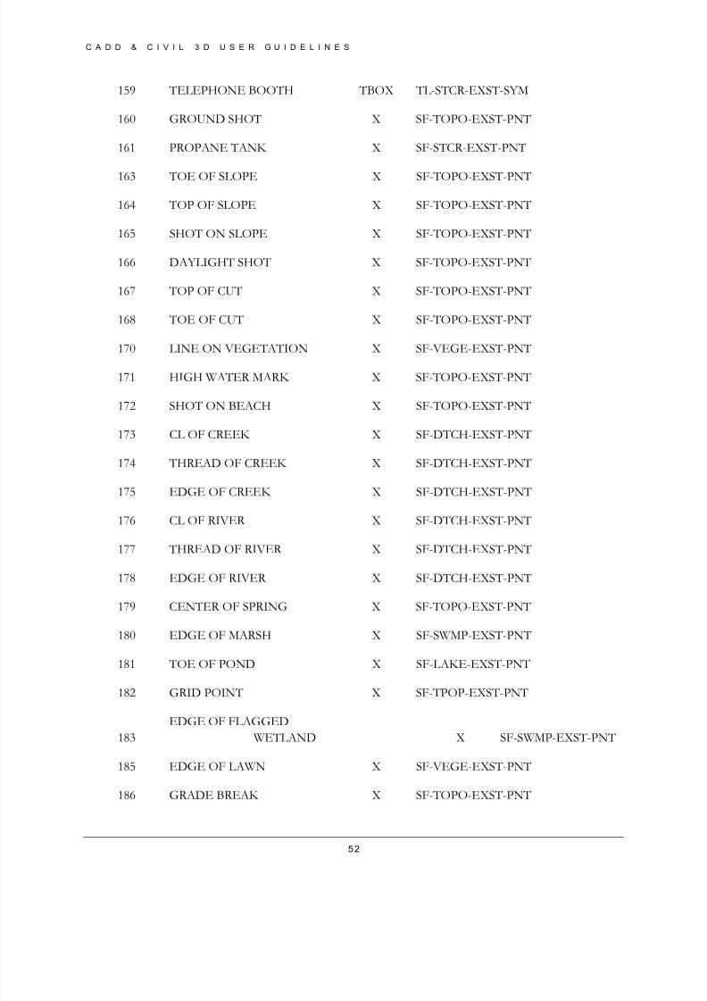
159 TELEPHONE BOOTH TBOX TL-STCR-EXST-SYM
160 GROUND SHOT X SF-TOPO-EXST-PNT
161 PROPANE TANK X SF-STCR-EXST-PNT
163 TOE OF SLOPE X SF-TOPO-EXST-PNT
164 TOP OF SLOPE X SF-TOPO-EXST-PNT
165 SHOT ON SLOPE X SF-TOPO-EXST-PNT
166 DAYLIGHT SHOT X SF-TOPO-EXST-PNT
167 TOP OF CUT X SF-TOPO-EXST-PNT
168 TOE OF CUT X SF-TOPO-EXST-PNT
170 LINE ON VEGETATION X SF-VEGE-EXST-PNT
171 HIGH WATER MARK X SF-TOPO-EXST-PNT
172 SHOT ON BEACH X SF-TOPO-EXST-PNT
173 CL OF CREEK X SF-DTCH-EXST-PNT
174 THREAD OF CREEK X SF-DTCH-EXST-PNT
175 EDGE OF CREEK X SF-DTCH-EXST-PNT
176 CL OF RIVER X SF-DTCH-EXST-PNT
177 THREAD OF RIVER X SF-DTCH-EXST-PNT
178 EDGE OF RIVER X SF-DTCH-EXST-PNT
179 CENTER OF SPRING X SF-TOPO-EXST-PNT
180 EDGE OF MARSH X SF-SWMP-EXST-PNT
181 TOE OF POND X SF-LAKE-EXST-PNT
182 GRID POINT X SF-TPOP-EXST-PNT
183
EDGE OF FLAGGED
WETLAND X SF-SWMP-EXST-PNT
185 EDGE OF LAWN X SF-VEGE-EXST-PNT
186 GRADE BREAK X SF-TOPO-EXST-PNT
8/8/2019 Tcpw Cadd Manual 03-01-10
http://slidepdf.com/reader/full/tcpw-cadd-manual-03-01-10 53/73
C A D D & C I V I L 3 D U S E R G U I D E L I N E S
53
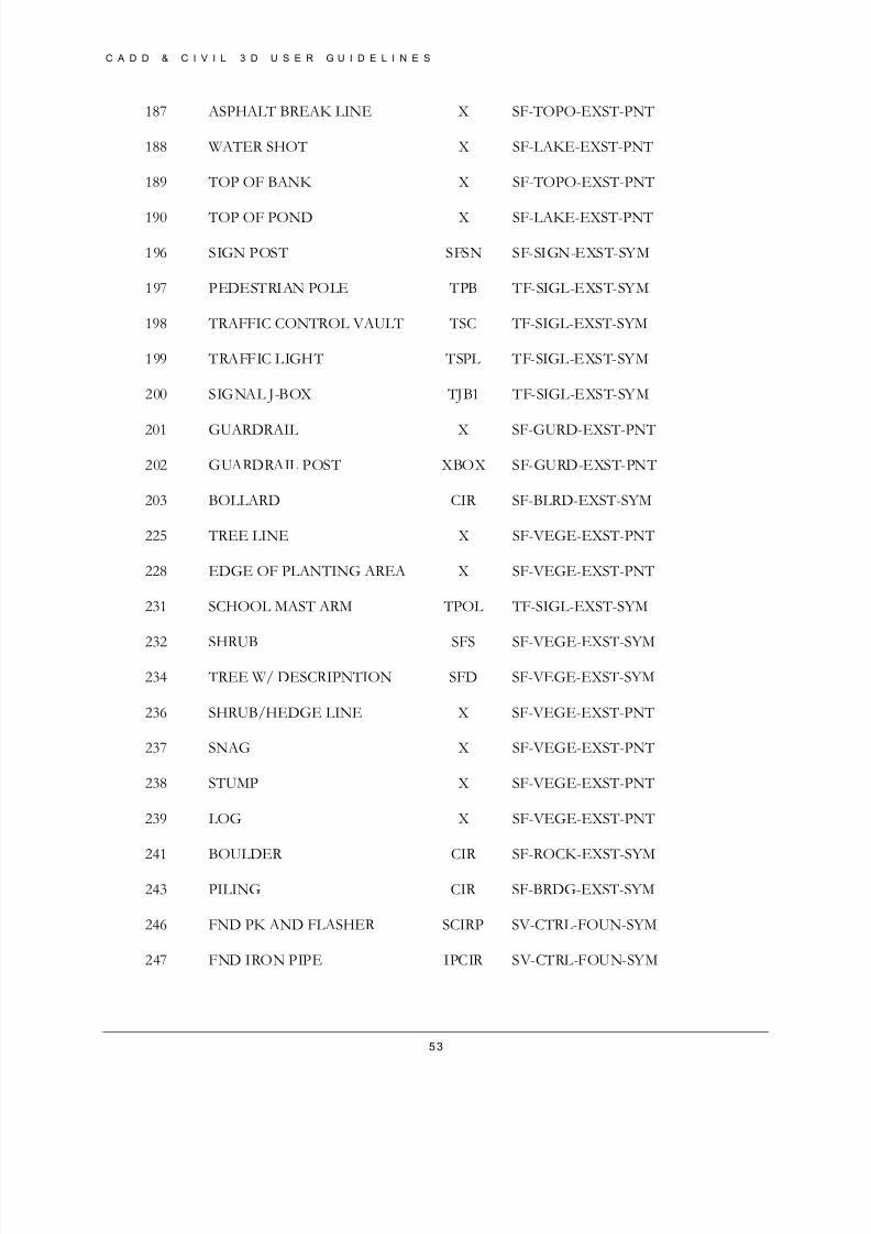
187 ASPHALT BREAK LINE X SF-TOPO-EXST-PNT
188 WATER SHOT X SF-LAKE-EXST-PNT
189 TOP OF BANK X SF-TOPO-EXST-PNT
190 TOP OF POND X SF-LAKE-EXST-PNT
196 SIGN POST SFSN SF-SIGN-EXST-SYM
197 PEDESTRIAN POLE TPB TF-SIGL-EXST-SYM
198 TRAFFIC CONTROL VAULT TSC TF-SIGL-EXST-SYM
199 TRAFFIC LIGHT TSPL TF-SIGL-EXST-SYM
200 SIGNAL J-BOX TJB1 TF-SIGL-EXST-SYM
201 GUARDRAIL X SF-GURD-EXST-PNT
202 GUARDRAIL POST XBOX SF-GURD-EXST-PNT
203 BOLLARD CIR SF-BLRD-EXST-SYM
225 TREE LINE X SF-VEGE-EXST-PNT
228 EDGE OF PLANTING AREA X SF-VEGE-EXST-PNT
231 SCHOOL MAST ARM TPOL TF-SIGL-EXST-SYM
232 SHRUB SFS SF-VEGE-EXST-SYM
234 TREE W/ DESCRIPNTION SFD SF-VEGE-EXST-SYM
236 SHRUB/HEDGE LINE X SF-VEGE-EXST-PNT
237 SNAG X SF-VEGE-EXST-PNT
238 STUMP X SF-VEGE-EXST-PNT
239 LOG X SF-VEGE-EXST-PNT
241 BOULDER CIR SF-ROCK-EXST-SYM
243 PILING CIR SF-BRDG-EXST-SYM
246 FND PK AND FLASHER SCIRP SV-CTRL-FOUN-SYM
247 FND IRON PIPE IPCIR SV-CTRL-FOUN-SYM
8/8/2019 Tcpw Cadd Manual 03-01-10
http://slidepdf.com/reader/full/tcpw-cadd-manual-03-01-10 54/73
C A D D & C I V I L 3 D U S E R G U I D E L I N E S
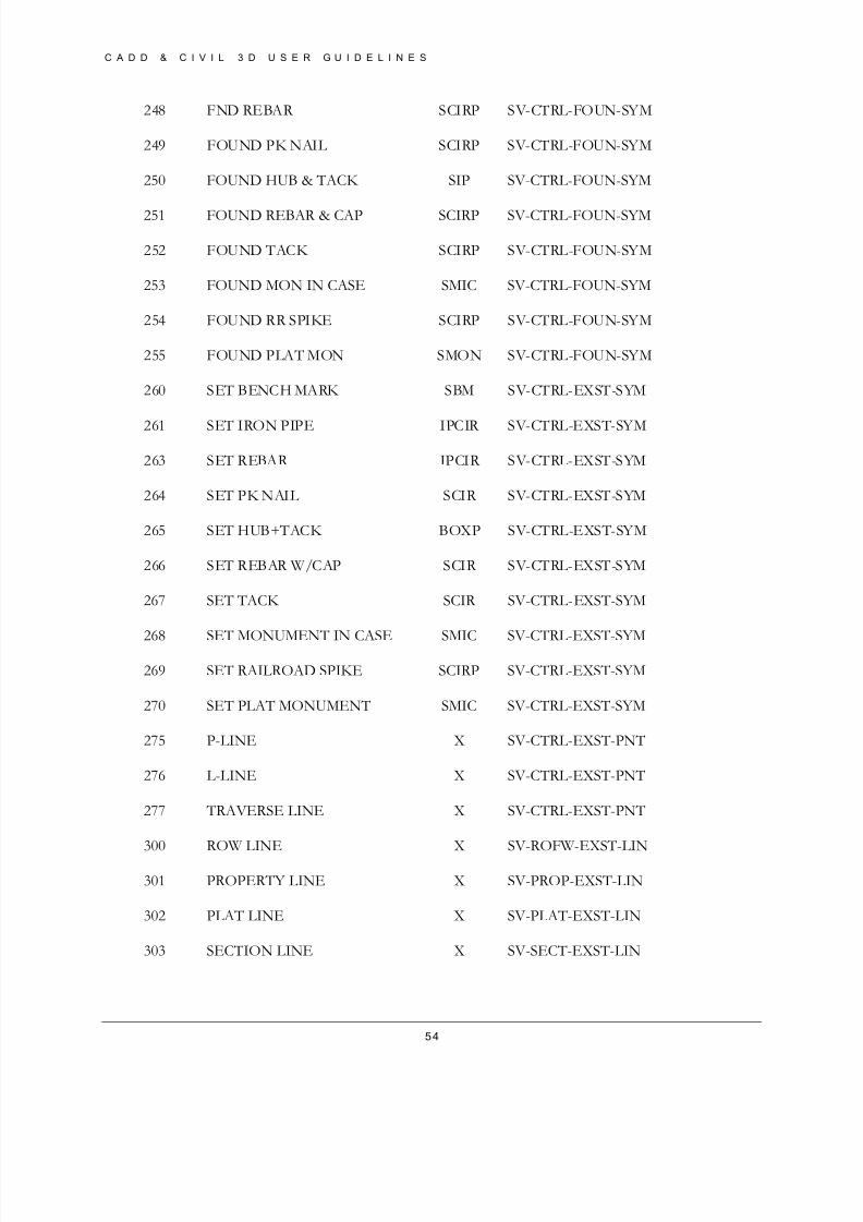
54
248 FND REBAR SCIRP SV-CTRL-FOUN-SYM
249 FOUND PK NAIL SCIRP SV-CTRL-FOUN-SYM
250 FOUND HUB & TACK SIP SV-CTRL-FOUN-SYM
251 FOUND REBAR & CAP SCIRP SV-CTRL-FOUN-SYM
252 FOUND TACK SCIRP SV-CTRL-FOUN-SYM
253 FOUND MON IN CASE SMIC SV-CTRL-FOUN-SYM
254 FOUND RR SPIKE SCIRP SV-CTRL-FOUN-SYM
255 FOUND PLAT MON SMON SV-CTRL-FOUN-SYM
260 SET BENCH MARK SBM SV-CTRL-EXST-SYM
261 SET IRON PIPE IPCIR SV-CTRL-EXST-SYM
263 SET REBAR IPCIR SV-CTRL-EXST-SYM
264 SET PK NAIL SCIR SV-CTRL-EXST-SYM
265 SET HUB+TACK BOXP SV-CTRL-EXST-SYM
266 SET REBAR W/CAP SCIR SV-CTRL-EXST-SYM
267 SET TACK SCIR SV-CTRL-EXST-SYM
268 SET MONUMENT IN CASE SMIC SV-CTRL-EXST-SYM
269 SET RAILROAD SPIKE SCIRP SV-CTRL-EXST-SYM
270 SET PLAT MONUMENT SMIC SV-CTRL-EXST-SYM
275 P-LINE X SV-CTRL-EXST-PNT
276 L-LINE X SV-CTRL-EXST-PNT
277 TRAVERSE LINE X SV-CTRL-EXST-PNT
300 ROW LINE X SV-ROFW-EXST-LIN
301 PROPERTY LINE X SV-PROP-EXST-LIN
302 PLAT LINE X SV-PLAT-EXST-LIN
303 SECTION LINE X SV-SECT-EXST-LIN

8/8/2019 Tcpw Cadd Manual 03-01-10
http://slidepdf.com/reader/full/tcpw-cadd-manual-03-01-10 55/73
C A D D & C I V I L 3 D U S E R G U I D E L I N E S
55
L inework
FIELD CODE BREAKLINE LAYER LINETYPE
1 Yes SF-BLDG-EXST-LIN EXBUILD
2 Yes SF-BLDG-EXST-LIN EXBUILD
3 Yes SF-BLDG-EXST-LIN EXBUILD
4 Yes SF-BLDG-EXST-LIN EXBUILD
5 Yes SF-BLDG-EXST-LIN EXBUILD
6 Yes SF-BLDG-EXST-LIN EXBUILD7 Yes SF-BLDG-EXST-LIN EXBUILD
8 Yes SF-BLDG-EXST-LIN EXBUILD
9 Yes SF-BLDG-EXST-LIN EXBUILD
10 Yes SF-BLDG-EXST-LIN EXBUILD
15 Yes SV-CNTL-EXST-LIN EXCNTL
16 Yes SF-PVMT-EXST-LIN HIDDEN2
17 No TF-CHAN-EXST-LIN HIDDEN2
18 Yes SF-GRVL-EXST-LIN HIDDEN2
19 Yes SF-GRVL-EXST-LIN HIDDEN2
20 Yes SF-PVMT-EXST-LIN HIDDEN2
21 Yes SF-GRVL-EXST-LIN HIDDEN2
22 Yes SF-PVMT-EXST-LIN HIDDEN2
23 Yes SF-PVMT-EXST-LIN HIDDEN2
24 Yes SF-PVMT-EXST-LIN HIDDEN2
25 No SF-PVMT-EXST-LIN HIDDEN2
26 Yes SF-PVMT-EXST-LIN HIDDEN2
27 Yes SF-RLRD-EXST-LIN Continuous
28 Yes SF-RLRD-EXST-LIN Continuous
29 Yes SF-BRDG-EXST-LIN HIDDEN2
30 Yes SF-BRDG-EXST-LIN HIDDEN2
31 No 0
32 No TF-CHAN-EXST-LIN HIDDEN2
33 No TF-CHAN-EXST-LIN HIDDEN2
34 No 0
304 1/4 SECTION LINE X SV-QSCT-EXST-LIN
305 1/16 SECTION LINE X SV-16ST-EXST-LIN
550 MISC X MISC_PNT
8/8/2019 Tcpw Cadd Manual 03-01-10
http://slidepdf.com/reader/full/tcpw-cadd-manual-03-01-10 56/73
C A D D & C I V I L 3 D U S E R G U I D E L I N E S
56
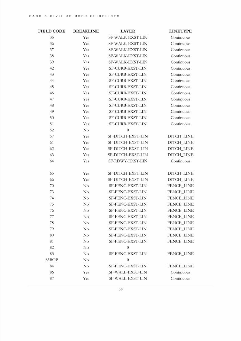
FIELD CODE BREAKLINE LAYER LINETYPE
35 Yes SF-WALK-EXST-LIN Continuous
36 Yes SF-WALK-EXST-LIN Continuous
37 Yes SF-WALK-EXST-LIN Continuous
38 Yes SF-WALK-EXST-LIN Continuous
39 Yes SF-WALK-EXST-LIN Continuous
42 Yes SF-CURB-EXST-LIN Continuous
43 Yes SF-CURB-EXST-LIN Continuous
44 Yes SF-CURB-EXST-LIN Continuous
45 Yes SF-CURB-EXST-LIN Continuous
46 Yes SF-CURB-EXST-LIN Continuous
47 Yes SF-CURB-EXST-LIN Continuous
48 Yes SF-CURB-EXST-LIN Continuous
49 Yes SF-CURB-EXST-LIN Continuous
50 Yes SF-CURB-EXST-LIN Continuous51 Yes SF-CURB-EXST-LIN Continuous
52 No 0
57 Yes SF-DITCH-EXST-LIN DITCH_LINE
61 Yes SF-DITCH-EXST-LIN DITCH_LINE
62 Yes SF-DITCH-EXST-LIN DITCH_LINE
63 Yes SF-DITCH-EXST-LIN DITCH_LINE
64 Yes SF-RDWY-EXST-LIN Continuous
65 Yes SF-DITCH-EXST-LIN DITCH_LINE
66 Yes SF-DITCH-EXST-LIN DITCH_LINE70 No SF-FENC-EXST-LIN FENCE_LINE
73 No SF-FENC-EXST-LIN FENCE_LINE
74 No SF-FENC-EXST-LIN FENCE_LINE
75 No SF-FENC-EXST-LIN FENCE_LINE
76 No SF-FENC-EXST-LIN FENCE_LINE
77 No SF-FENC-EXST-LIN FENCE_LINE
78 No SF-FENC-EXST-LIN FENCE_LINE
79 No SF-FENC-EXST-LIN FENCE_LINE
80 No SF-FENC-EXST-LIN FENCE_LINE
81 No SF-FENC-EXST-LIN FENCE_LINE
82 No 0
83 No SF-FENC-EXST-LIN FENCE_LINE
83BOP No 0
84 No SF-FENC-EXST-LIN FENCE_LINE
86 Yes SF-WALL-EXST-LIN Continuous
87 Yes SF-WALL-EXST-LIN Continuous

8/8/2019 Tcpw Cadd Manual 03-01-10
http://slidepdf.com/reader/full/tcpw-cadd-manual-03-01-10 57/73
C A D D & C I V I L 3 D U S E R G U I D E L I N E S
57
FIELD CODE BREAKLINE LAYER LINETYPE
88 Yes SF-WALL-EXST-LIN Continuous
89 Yes SF-WALL-EXST-LIN Continuous
90 Yes SF-WALL-EXST-LIN Continuous
91 Yes SF-WALL-EXST-LIN Continuous
92 Yes SF-WALL-EXST-LIN Continuous
93 Yes SF-WALL-EXST-LIN Continuous
93ESMN No 0
93RW No 0
94 No 0
95 No 0
97 No 0
113 No SD-GLIN-EXST-LIN X_STORM_DRAIN114 No SD-GLIN-EXST-LIN X_STORM_DRAIN
115 No SD-GLIN-EXST-LIN X_STORM_DRAIN
117 No SD-GLIN-EXST-LIN X_STORM_DRAIN
119 No SD-GLIN-EXST-LIN X_STORM_DRAIN
146 No 0
149 No TV-BLIN-EXST-LIN X_CABLE_TV
150 No TL-FOBLIN-EXST-LIN FIBER_OPTIC
151 No PO-BLIN-EXST-LIN X_POWER_BURIED
152 No GS-PLIN-EXST-LIN X_GAS_LINE
153 No TL-BLIN-EXST-LIN X_TELE_CABLE_BURIED154 No WA-PLIN-EXST-LIN X_WATER_LINE
155 No SS-PLIN-EXST-LIN X_SANITARY_SEWER
156 No SD-GLIN-EXST-LIN X_STORM_DRAIN
162 No 0
163 Yes SF-TOPO-EXST-LIN Continuous
164 Yes SF-TOPO-EXST-LIN Continuous
165 No 0
167 Yes SF-TOPO-EXST-LIN Continuous
168 Yes SF-TOPO-EXST-LIN Continuous
170 No SF-VEGE-EXST-LIN Continuous
173 No SF-CREK-EXST-LIN Continuous
174 No SF-CREK-EXST-LIN Continuous
175 No SF-CREK-EXST-LIN Continuous
176 No SF-RIVR-EXST-LIN STREAM
177 No SF-RIVR-EXST-LIN STREAM
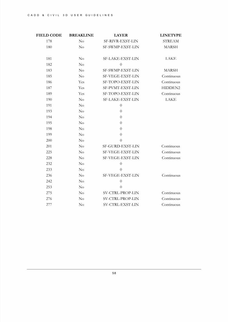
8/8/2019 Tcpw Cadd Manual 03-01-10
http://slidepdf.com/reader/full/tcpw-cadd-manual-03-01-10 58/73
C A D D & C I V I L 3 D U S E R G U I D E L I N E S
58
FIELD CODE BREAKLINE LAYER LINETYPE
178 No SF-RIVR-EXST-LIN STREAM
180 No SF-SWMP-EXST-LIN MARSH
181 No SF-LAKE-EXST-LIN LAKE
182 No 0
183 No SF-SWMP-EXST-LIN MARSH
185 No SF-VEGE-EXST-LIN Continuous
186 Yes SF-TOPO-EXST-LIN Continuous
187 Yes SF-PVMT-EXST-LIN HIDDEN2
189 Yes SF-TOPO-EXST-LIN Continuous
190 No SF-LAKE-EXST-LIN LAKE
191 No 0
193 No 0194 No 0
195 No 0
198 No 0
199 No 0
200 No 0
201 No SF-GURD-EXST-LIN Continuous
225 No SF-VEGE-EXST-LIN Continuous
228 No SF-VEGE-EXST-LIN Continuous
232 No 0
233 No 0236 No SF-VEGE-EXST-LIN Continuous
242 No 0
253 No 0
275 No SV-CTRL-PROP-LIN Continuous
276 No SV-CTRL-PROP-LIN Continuous
277 No SV-CTRL-EXST-LIN Continuous
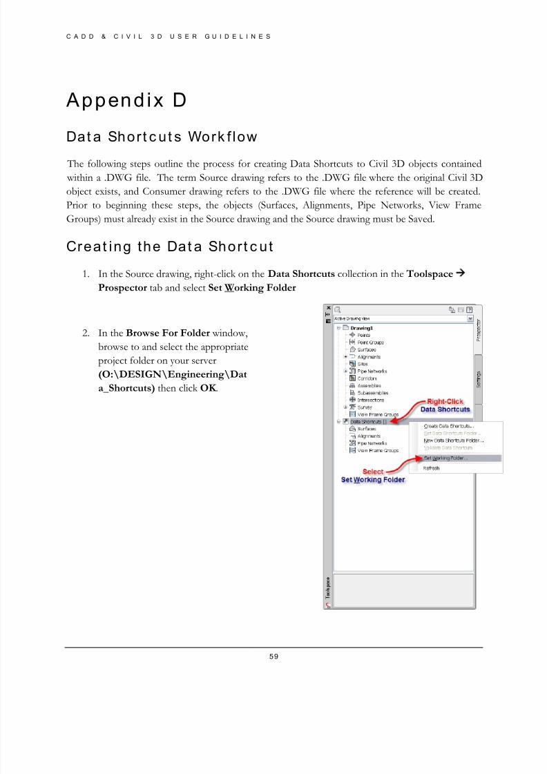
8/8/2019 Tcpw Cadd Manual 03-01-10
http://slidepdf.com/reader/full/tcpw-cadd-manual-03-01-10 59/73
C A D D & C I V I L 3 D U S E R G U I D E L I N E S
59
Append ix D
Dat a Shor t c ut s Work f low
The following steps outline the process for creating Data Shortcuts to Civil 3D objects contained
within a .DWG file. The term Source drawing refers to the .DWG file where the original Civil 3D
object exists, and Consumer drawing refers to the .DWG file where the reference will be created.
Prior to beginning these steps, the objects (Surfaces, Alignments, Pipe Networks, View Frame
Groups) must already exist in the Source drawing and the Source drawing must be Saved.
Creat ing the Dat a Shor t c ut
1. In the Source drawing, right-click on the Data Shortcuts collection in the Toolspace Prospector tab and select Set Working Folder
2. In the Browse For Folder window,
browse to and select the appropriate
project folder on your server
(O:\DESIGN\Engineering\Dat
a_Shortcuts) then click OK .
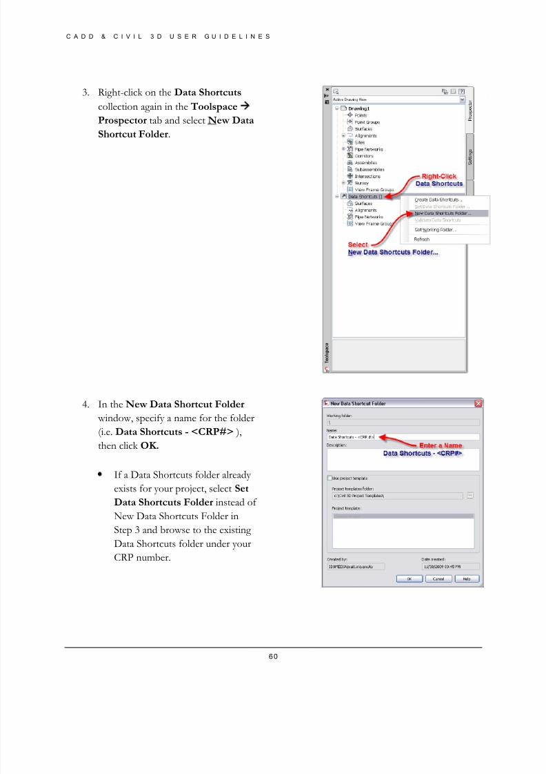
8/8/2019 Tcpw Cadd Manual 03-01-10
http://slidepdf.com/reader/full/tcpw-cadd-manual-03-01-10 60/73
C A D D & C I V I L 3 D U S E R G U I D E L I N E S
60
3. Right-click on the Data Shortcuts
collection again in the Toolspace
Prospector tab and select New Data
Shortcut Folder.
4. In the New Data Shortcut Folder window, specify a name for the folder
(i.e. Data Shortcuts - <CRP#> ),
then click OK.
• If a Data Shortcuts folder already
exists for your project, select Set
Data Shortcuts Folder instead of
New Data Shortcuts Folder in
Step 3 and browse to the existing
Data Shortcuts folder under yourCRP number.
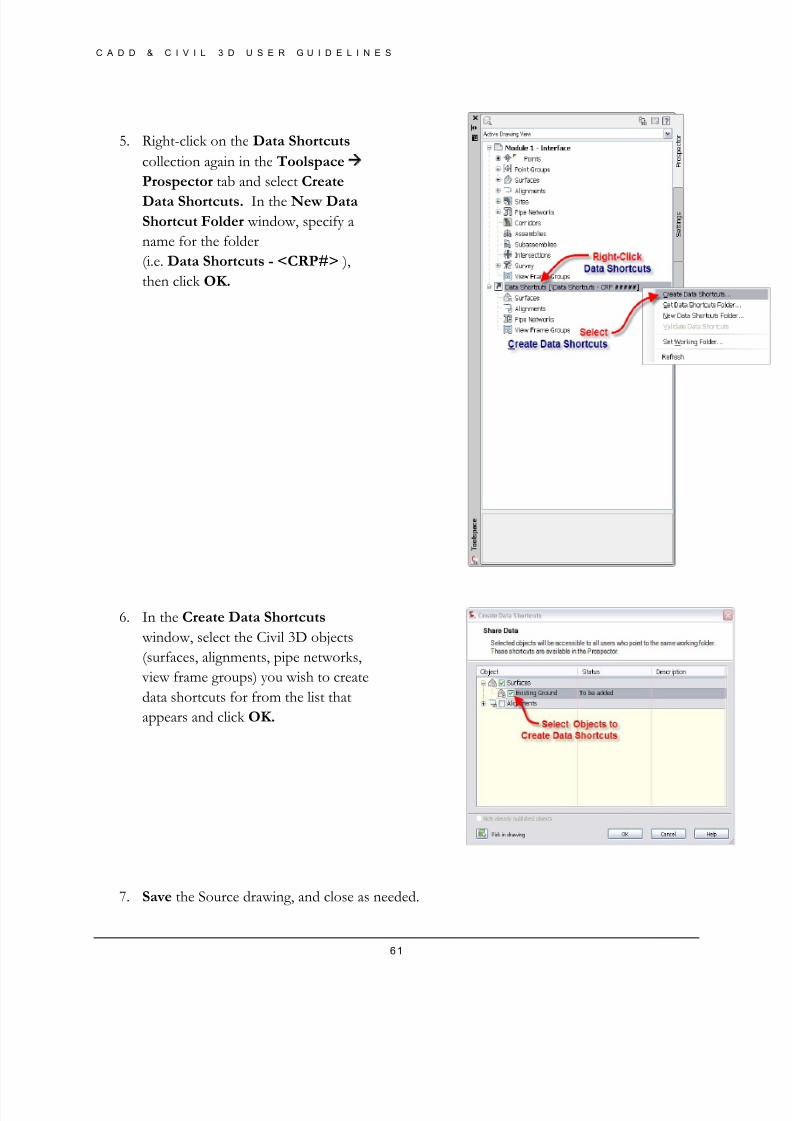
8/8/2019 Tcpw Cadd Manual 03-01-10
http://slidepdf.com/reader/full/tcpw-cadd-manual-03-01-10 61/73
C A D D & C I V I L 3 D U S E R G U I D E L I N E S
61
5. Right-click on the Data Shortcuts
collection again in the Toolspace
Prospector tab and select Create
Data Shortcuts. In the New Data
Shortcut Folder window, specify a
name for the folder
(i.e. Data Shortcuts - <CRP#> ),
then click OK.
6. In the Create Data Shortcuts
window, select the Civil 3D objects
(surfaces, alignments, pipe networks,
view frame groups) you wish to create
data shortcuts for from the list that
appears and click OK.
7. Save the Source drawing, and close as needed.
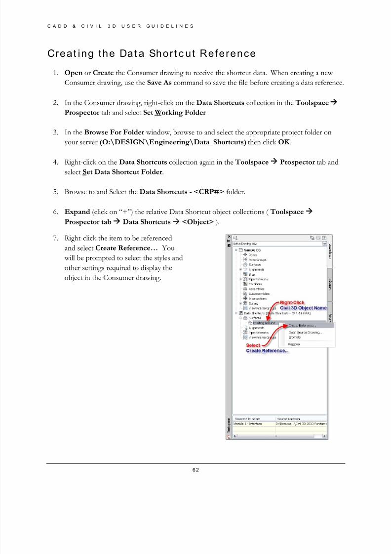
8/8/2019 Tcpw Cadd Manual 03-01-10
http://slidepdf.com/reader/full/tcpw-cadd-manual-03-01-10 62/73
C A D D & C I V I L 3 D U S E R G U I D E L I N E S
62
Creat ing the Dat a Shor t c ut Reference
1. Open or Create the Consumer drawing to receive the shortcut data. When creating a new
Consumer drawing, use the Save As command to save the file before creating a data reference.
2. In the Consumer drawing, right-click on the Data Shortcuts collection in the Toolspace
Prospector tab and select Set Working Folder
3. In the Browse For Folder window, browse to and select the appropriate project folder on
your server (O:\DESIGN\Engineering\Data_Shortcuts) then click OK .
4. Right-click on the Data Shortcuts collection again in the Toolspace Prospector tab and
select Set Data Shortcut Folder.
5.
Browse to and Select the Data Shortcuts - <CRP#> folder.
6. Expand (click on “+”) the relative Data Shortcut object collections ( Toolspace
Prospector tab Data Shortcuts <Object> ).
7. Right-click the item to be referenced
and select Create Reference… You
will be prompted to select the styles and
other settings required to display the
object in the Consumer drawing.

8/8/2019 Tcpw Cadd Manual 03-01-10
http://slidepdf.com/reader/full/tcpw-cadd-manual-03-01-10 63/73
C A D D & C I V I L 3 D U S E R G U I D E L I N E S
63
8. Repeat for all objects as needed. Objects will appear in the Prospector tab collections once the
references are created.
9. Save the Consumer drawing.
*Steps 1 through 5 can also be accessed via the Ribbon Interface Manage Tab Data
Shortcuts Panel

8/8/2019 Tcpw Cadd Manual 03-01-10
http://slidepdf.com/reader/full/tcpw-cadd-manual-03-01-10 64/73
C A D D & C I V I L 3 D U S E R G U I D E L I N E S
64
Append ix E
Survey Database Work f low
The survey department should be responsible for setting up a survey database for each project,
The folder “Database” will be added to the CRP project folder template under the “Survey” folder
for use in all new projects
Survey shall use a Survey Database for all survey related processes in Civil 3D including importing
points and linework; this gives the user more control over the data and more functionality within the
program. A survey database is also the only way to bring in linework automatically using ASCII
files.
Survey user settings will need to be set for each individual machine that will be used to edit survey data, settings will need to be changed to access certain files including the figure prefix database (line
work definition file) and the linework code set (for reading ASCII point files). The description key
set (point definition file) is set automatically in the Thurston Co. standard Civil 3d template and it
can be dragged and dropped into older files.
One of the only changes to be made with the process of collecting shots in the field will be changing
the linework descriptors to match the codes defined in the linework code set, the new codes used
will need to be implemented by survey and used for all new projects.
Creat ing a Survey Database
The following steps outline the process for creating a Survey Database using the Civil 3D Toolspace
Survey tab. Survey Databases are a way for Surveyors to organize and store survey information in
an external source. Setting up and creating a Survey database is one way for surveyors to back up
their original topographic data collected in the field.
New Survey Dat abase
8. In the drawing file, switch to the
Survey tab of the Toolspace. Right-
click on the Survey Databases
collection and select Set the Working
Folder…
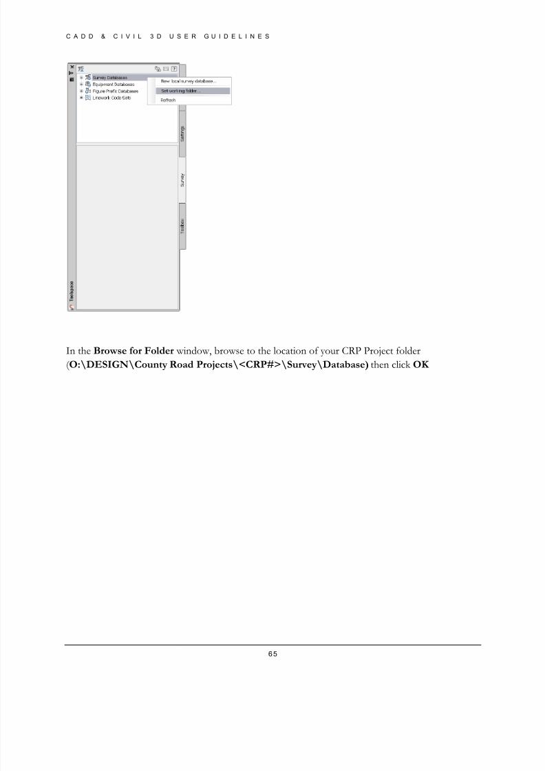
8/8/2019 Tcpw Cadd Manual 03-01-10
http://slidepdf.com/reader/full/tcpw-cadd-manual-03-01-10 65/73
C A D D & C I V I L 3 D U S E R G U I D E L I N E S
65
In the Browse for Folder window, browse to the location of your CRP Project folder
( O:\DESIGN\County Road Projects\<CRP#>\Survey\Database) then click OK
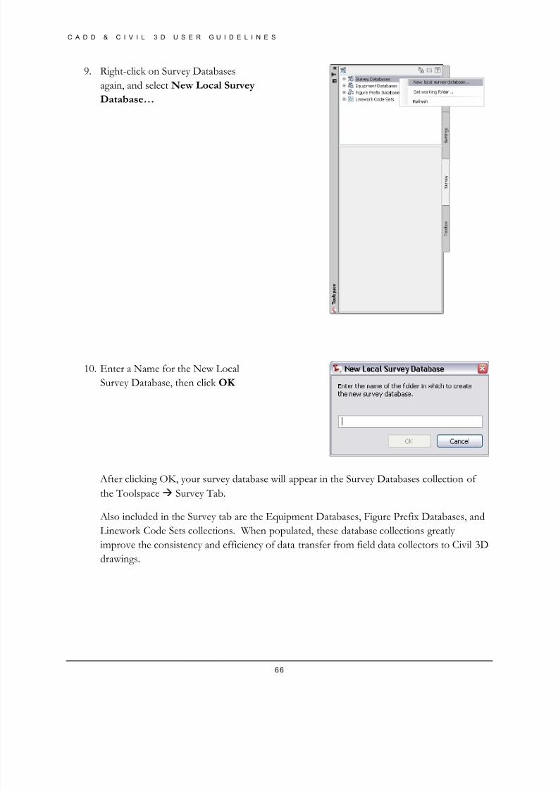
8/8/2019 Tcpw Cadd Manual 03-01-10
http://slidepdf.com/reader/full/tcpw-cadd-manual-03-01-10 66/73
C A D D & C I V I L 3 D U S E R G U I D E L I N E S
66
9. Right-click on Survey Databases
again, and select New Local Survey
Database…
10. Enter a Name for the New Local
Survey Database, then click OK
After clicking OK, your survey database will appear in the Survey Databases collection of
the Toolspace Survey Tab.
Also included in the Survey tab are the Equipment Databases, Figure Prefix Databases, and
Linework Code Sets collections. When populated, these database collections greatly
improve the consistency and efficiency of data transfer from field data collectors to Civil 3D
drawings.
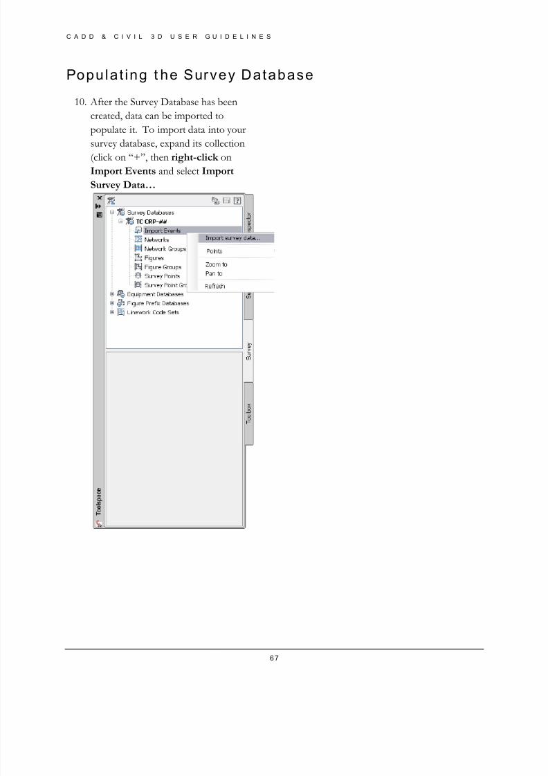
8/8/2019 Tcpw Cadd Manual 03-01-10
http://slidepdf.com/reader/full/tcpw-cadd-manual-03-01-10 67/73
C A D D & C I V I L 3 D U S E R G U I D E L I N E S
67
Populat ing t he Survey Database
10. After the Survey Database has been
created, data can be imported to
populate it. To import data into your
survey database, expand its collection
(click on “+”, then right-click on
Import Events and select Import
Survey Data…
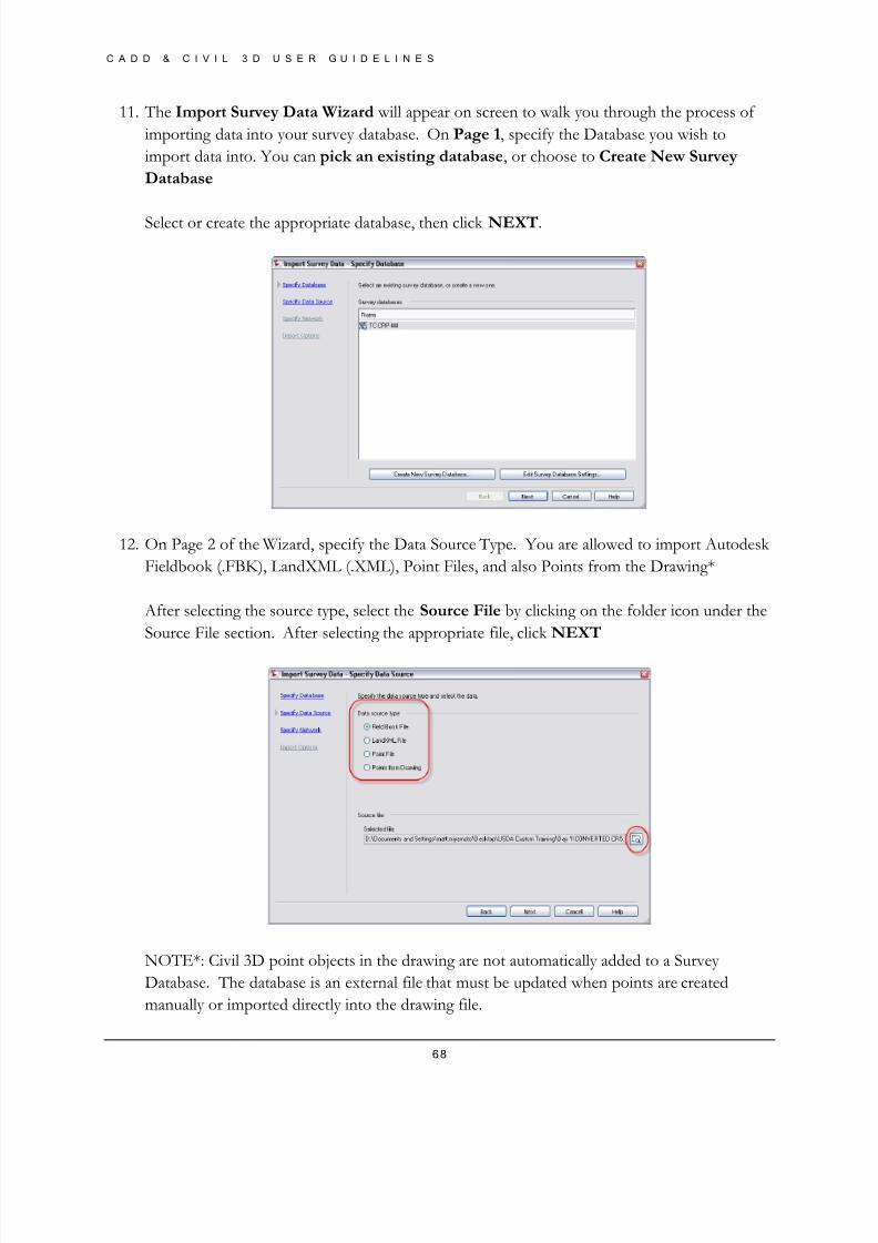
8/8/2019 Tcpw Cadd Manual 03-01-10
http://slidepdf.com/reader/full/tcpw-cadd-manual-03-01-10 68/73
C A D D & C I V I L 3 D U S E R G U I D E L I N E S
68
11. The Import Survey Data Wizard will appear on screen to walk you through the process of
importing data into your survey database. On Page 1, specify the Database you wish to
import data into. You can pick an existing database, or choose to Create New Survey
Database
Select or create the appropriate database, then click NEXT.
12. On Page 2 of the Wizard, specify the Data Source Type. You are allowed to import Autodesk
Fieldbook (.FBK), LandXML (.XML), Point Files, and also Points from the Drawing*
After selecting the source type, select the Source File by clicking on the folder icon under the
Source File section. After selecting the appropriate file, click NEXT
NOTE*: Civil 3D point objects in the drawing are not automatically added to a Survey
Database. The database is an external file that must be updated when points are created
manually or imported directly into the drawing file.
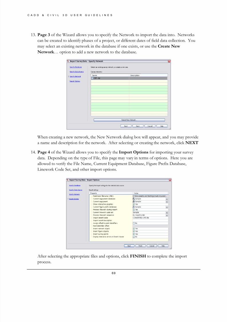
8/8/2019 Tcpw Cadd Manual 03-01-10
http://slidepdf.com/reader/full/tcpw-cadd-manual-03-01-10 69/73
C A D D & C I V I L 3 D U S E R G U I D E L I N E S
69
13. Page 3 of the Wizard allows you to specify the Network to import the data into. Networks
can be created to identify phases of a project, or different dates of field data collection. You
may select an existing network in the database if one exists, or use the Create New
Network … option to add a new network to the database.
When creating a new network, the New Network dialog box will appear, and you may provide
a name and description for the network. After selecting or creating the network, click NEXT
14. Page 4 of the Wizard allows you to specify the Import Options for importing your survey
data. Depending on the type of File, this page may vary in terms of options. Here you are
allowed to verify the File Name, Current Equipment Database, Figure Prefix Database,
Linework Code Set, and other import options.
After selecting the appropriate files and options, click FINISH to complete the import
process.
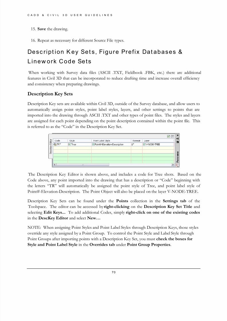
8/8/2019 Tcpw Cadd Manual 03-01-10
http://slidepdf.com/reader/full/tcpw-cadd-manual-03-01-10 70/73
C A D D & C I V I L 3 D U S E R G U I D E L I N E S
70
15. Save the drawing.
16. Repeat as necessary for different Source File types.
Desc r ip t ion K ey Set s , Figure Pref ix Dat abases &
L inew ork Code Sets
When working with Survey data files (ASCII .TXT, Fieldbook .FBK, etc.) there are additional
features in Civil 3D that can be incorporated to reduce drafting time and increase overall efficiency
and consistency when preparing drawings.
Description Key Sets
Description Key sets are available within Civil 3D, outside of the Survey database, and allow users to
automatically assign point styles, point label styles, layers, and other settings to points that are
imported into the drawing through ASCII .TXT and other types of point files. The styles and layers
are assigned for each point depending on the point description contained within the point file. This
is referred to as the “Code” in the Description Key Set.
The Description Key Editor is shown above, and includes a code for Tree shots. Based on the
Code above, any point imported into the drawing that has a description or “Code” beginning with
the letters “TR” will automatically be assigned the point style of Tree, and point label style of
Point#-Elevation-Description. The Point Object will also be placed on the layer V-NODE-TREE.
Description Key Sets can be found under the Points collection in the Settings tab of the
Toolspace. The editor can be accessed by right-clicking on the Description Key Set Title and
selecting Edit Keys... To add additional Codes, simply right-click on one of the existing codes
in the DescKey Editor and select New…
NOTE: When assigning Point Styles and Point Label Styles through Description Keys, those styles
override any style assigned by a Point Group. To control the Point Style and Label Style through
Point Groups after importing points with a Description Key Set, you must check the boxes for
Style and Point Label Style in the Overrides tab under Point Group Properties.
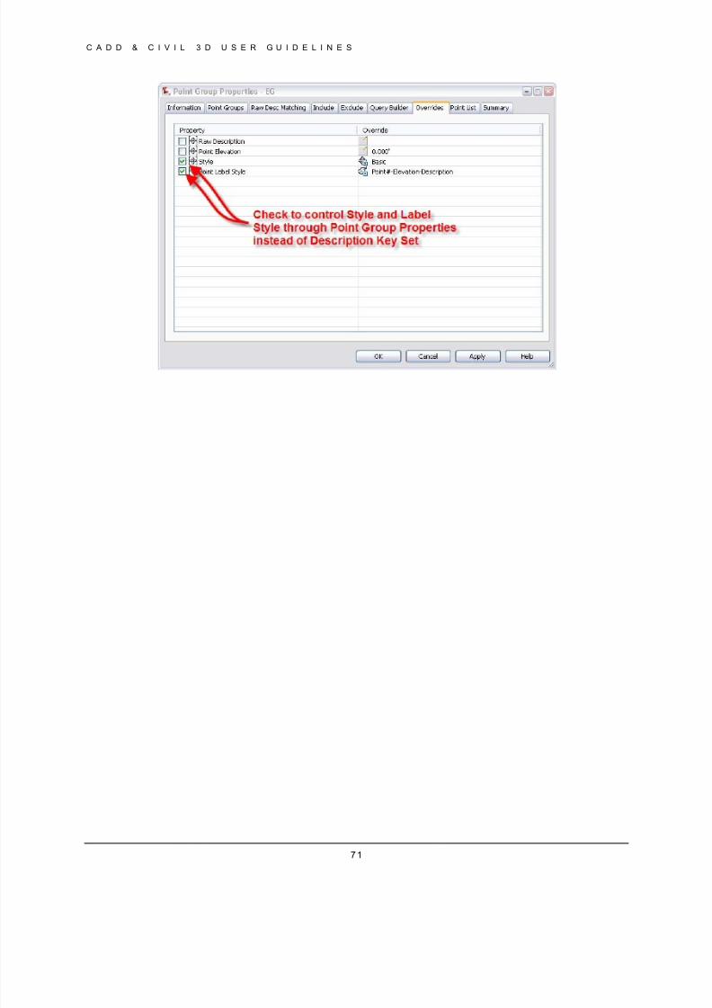
8/8/2019 Tcpw Cadd Manual 03-01-10
http://slidepdf.com/reader/full/tcpw-cadd-manual-03-01-10 71/73
C A D D & C I V I L 3 D U S E R G U I D E L I N E S
71
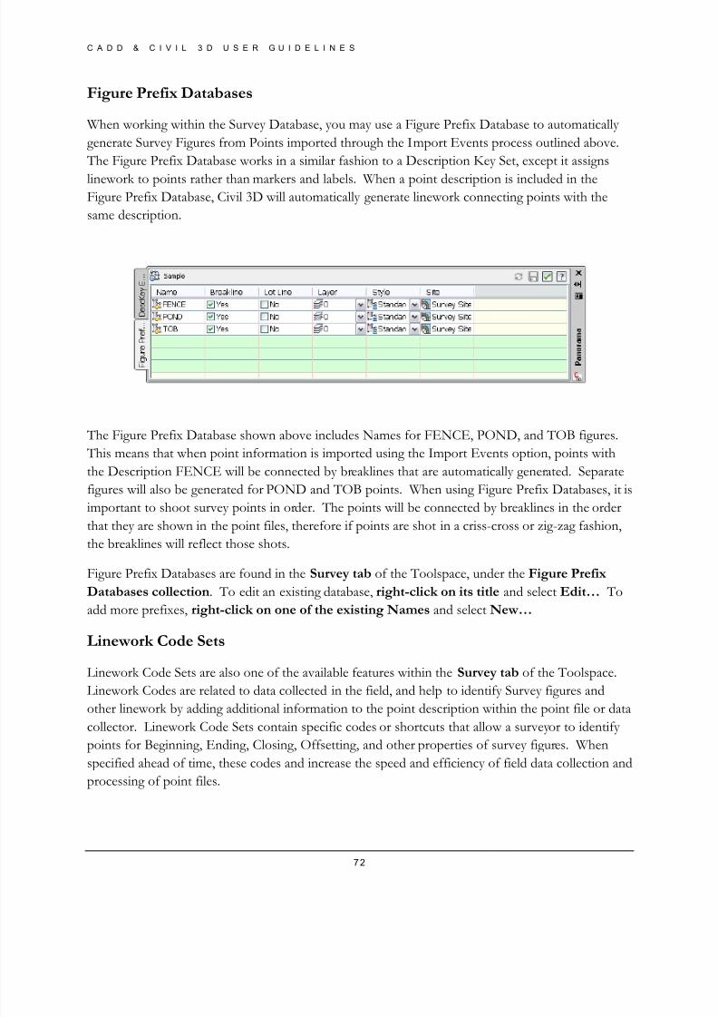
8/8/2019 Tcpw Cadd Manual 03-01-10
http://slidepdf.com/reader/full/tcpw-cadd-manual-03-01-10 72/73
C A D D & C I V I L 3 D U S E R G U I D E L I N E S
72
Figure Prefix Databases
When working within the Survey Database, you may use a Figure Prefix Database to automatically
generate Survey Figures from Points imported through the Import Events process outlined above.
The Figure Prefix Database works in a similar fashion to a Description Key Set, except it assigns
linework to points rather than markers and labels. When a point description is included in theFigure Prefix Database, Civil 3D will automatically generate linework connecting points with the
same description.
The Figure Prefix Database shown above includes Names for FENCE, POND, and TOB figures.
This means that when point information is imported using the Import Events option, points with
the Description FENCE will be connected by breaklines that are automatically generated. Separate
figures will also be generated for POND and TOB points. When using Figure Prefix Databases, it is
important to shoot survey points in order. The points will be connected by breaklines in the order
that they are shown in the point files, therefore if points are shot in a criss-cross or zig-zag fashion,
the breaklines will reflect those shots.
Figure Prefix Databases are found in the Survey tab of the Toolspace, under the Figure Prefix
Databases collection. To edit an existing database, right-click on its title and select Edit… To
add more prefixes, right-click on one of the existing Names and select New…
Linework Code Sets
Linework Code Sets are also one of the available features within the Survey tab of the Toolspace.
Linework Codes are related to data collected in the field, and help to identify Survey figures and
other linework by adding additional information to the point description within the point file or datacollector. Linework Code Sets contain specific codes or shortcuts that allow a surveyor to identify
points for Beginning, Ending, Closing, Offsetting, and other properties of survey figures. When
specified ahead of time, these codes and increase the speed and efficiency of field data collection and
processing of point files.
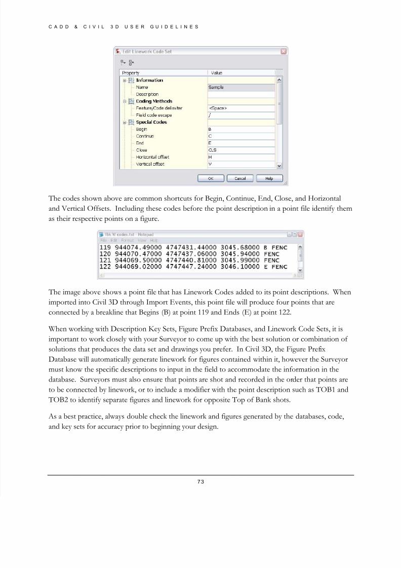
8/8/2019 Tcpw Cadd Manual 03-01-10
http://slidepdf.com/reader/full/tcpw-cadd-manual-03-01-10 73/73
C A D D & C I V I L 3 D U S E R G U I D E L I N E S
The codes shown above are common shortcuts for Begin, Continue, End, Close, and Horizontaland Vertical Offsets. Including these codes before the point description in a point file identify them
as their respective points on a figure.
The image above shows a point file that has Linework Codes added to its point descriptions. When
imported into Civil 3D through Import Events, this point file will produce four points that are
connected by a breakline that Begins (B) at point 119 and Ends (E) at point 122.
When working with Description Key Sets, Figure Prefix Databases, and Linework Code Sets, it is
important to work closely with your Surveyor to come up with the best solution or combination of
solutions that produces the data set and drawings you prefer. In Civil 3D, the Figure Prefix
Database will automatically generate linework for figures contained within it, however the Surveyor
must know the specific descriptions to input in the field to accommodate the information in the
database. Surveyors must also ensure that points are shot and recorded in the order that points are
to be connected by linework, or to include a modifier with the point description such as TOB1 and
TOB2 t id tif p t fi d li k f pp it T p f B k h t