TCP/IP Protocol –Transmission Control Protocol/Internetworking Protocol...
68
B.1 TCP/IP Protocol TCP/IP – Transmission Control Protocol/Internetworking Protocol (TCP/IP) – standard for the Internet – five layers = physical = data link = network = transport = application
Transcript of TCP/IP Protocol –Transmission Control Protocol/Internetworking Protocol...

B.1
TCP/IP Protocol
TCP/IP
– Transmission Control Protocol/Internetworking Protocol (TCP/IP)
– standard for the Internet
– five layers
=physical
= data link
=network
= transport
= application

B.2
TCP/IP Protocol (2)
TCP/IP and OSI model

B.3
IP protocol
– IP transports data in packets called datagrams.
– IP is an unreliable and connectionless datagram protocol -- a best-effort delivery service.
= “Best-effect” means that IP provides no error checking or tracking.
=Example of best-effort delivery service: post office
• The post office does its best to deliver the mail but dos not always succeed. If an unregistered letter is lost, it is up to the sender or would-be recipient to discover the loss and rectify the problem. The post office itself does not keep track of every letter and cannot notify a sender of loss or damage.

B.4
Datagram
– A datagram is a variable-length packet consisting of two parts:
= header
=data

B.5
Datagram (2)
– Version: version number of the IP. The current version is 4 (IPv4), with a binary value of 0100.
– Header length (HLEN): the length of the header.
– Service type: specify the type of service the sender desires such as the level of throughput, reliability, and delay.
– Total length: total length of the IP datagram.

B.6
Datagram (3)
– Identification, Flags and Fragmentation offset:
= used in fragmentation.
= A datagram when passing through different networks, may be divided into fragments to match the network frame size.
– Time to live: defines the number of hops a datagram can travel before it is discarded.
– Protocol: defines which upper-layer protocol data are encapsulated in the datagram (TCP, UDP, ICMP)

B.7
Datagram (4)
– Header checksum: to check the integrity of the header, not the rest of the packet.
– Source address: identifies the original source of the datagram.
– Destination address: identifies the final destination of the datagram.
– Options: network testing, security, and others.
B.8
Addressing
In addition to the physical addresses (MAC addresses at Layer 2), the Internet requires an additional address for identifies the connection of a host to its network.
Internet address
– 4 bytes
– Class type, netid, and hostid

B.9
Addressing (2)
– Netid: identifies the network to which a host is attached.
– The length of Netid and Hostid depends on the class of the address
Example: 10011110 10000100 00001110 00000001
= 158.132.14.1
Netid
Hostid

B.10
Addressing (2)
– The network number is managed ARIN (American Registry for Internet Number)
– The host number is managed by network administrators.

B.11
Classes
– Five classes
– Different classes are designed to cover the needs of different types of organization.

B.12
Classes (2)
Example, for class A networks, the maximum number of hosts is 224 = 16.8 millions
for class networks, the maximum number of hosts is 216 = 66 thousands

B.13
Classes (3)
Example, the decimal notation of the first byte:
Class A is 0 - 127 (00000000 - 011111111)
Class B is 128 - 191 (10000000 - 10111111)
Class C is 192 - 223 (11000000 - 11011111)
Class D is 224 - 239 (11100000 - 11101111)
Class E is 240 - 255 (11110000 - 11111111)
– Our campus network is a class B network as our address is 158.XXX.XXX.XXX

B.14
Classes (4)
For the whole address, we have

B.15
Classes (5)
– Class D is reserved for multicast address.
=Multicasting allows copies of a datagram to be passed to a select group of hosts rather than to an individual host

B.16
Classes (6)
Example,
Networkaddress

B.17
Subnetting
Subnetting
– division of network into smaller networks
– Example: a class B network with two levels of hierarchy (not subnetted)

B.18
Subnetting (2)
– A network with three levels of hierarchy (subnetted)
Trafficcan bereduced

B.19
Subnetting (3)
– In this example, a packet destined for host 141.14.21 still reaches router R1. The destination address of the IP datagram is still a class B address where 141.14 defines the netid and 2.21 defines the hostid.
– However, when the packet arrives at router R1, the interpretation of the IP address changes. Router R1 knows that the network 141.14 is physically divided into three sub-networks. It knows that the last two octets (2.21) define two things:
= subnetid
=hostid

B.20
Subnetting (4)
Example

B.21
Subnetting (5)
Example: consider a class B network, the IP structure is
– If subnetting is used, we “borrows” bits from the hostid field and designates them as the subnetid field.
– Any number of bits can be borrowed, as long as 2 bits remain.
– Example: 16 bits for netid
4 bits for subnetid
12 bits for hostid

B.22
Subnetting (6)
Subnet Mask
– all bits for netid and subnetid are ‘1’
– all bits for hostid are ‘0’
– Example: the subnet mask of the previous example is
11111111 11111111 11110000 00000000
In decimal notation, it is
255.255.240.0

B.23
Subnetting (7)
Masking
– to extracts the address of the physical network from an IP address.

B.24
Subnetting (8)
– The network address is extracted using the bit-wise AND operator.
– Example
The binary form of the IP address 141.14.2.21 is 10001101 00001110 00000010 00010101
The binary form of the mask 255.255.255.0 is
11111111 11111111 11111111 00000000
Taking AND operation, the result is
10001101 00001110 00000010 00000000
= 141.14.2.0

B.25
Subnetting (8)
Broadcasts
– IP addresses ending in all binary ones are reserved for broadcasts. The same is true for subnetworks.
– Example, for a Class B network (without subnetting) with network number 158.132.0.0, the IP address for broadcasts is 158.132.255.255
– Example, for a Class B network (with 8 bits used for subnetting) with subnetwork number 158.132.14.0, the IP address for broadcasts is 158.132.14.255.

B.26
Subnetting (9)
– Example, for a Class B network (with 4 bits used forsubnetting) with subnetwork number 158.132.160.0, the IP address for broadcasts is 158.132.?.?

B.27
Subnetting (10)
Example:
A Class C network has been assigned address 201.222.5.0. Assume that 20 subnets are needed, with 5 hosts per subnet.
We can subdivide the last octet (8 bits) into a subnet and a host portion, and then determine what the subnet mask will be.
1. Select a subnet field size that yields enough subnetworks.
Now, we choose 5 bits for subnetting
(25-2=30 > 20 and 2(8-5)-2=6 > 5).

B.28
Subnetting (11)
2. The subnet mask is 255.255.255.248 (29-bit mask).
3. The subnet addresses are all multiples of 8, i.e.,
201.222.5.16, 201.222.5.32,...

B.29
ARP
– Address Resolution Protocol (ARP)
– A data packet must contain both a destination physical address and a destination Internet Protocol (IP) address. If the data packet lacks one of these addresses, the data will not be passed to the upper levels.
– Example:
= physical address: 02-60-8C-01-02-03
= IP address: 158.132.14.1

B.30
ARP (2)
Example:
– When the source has determined the IP address for the destination, the source looks into the ARP table in order to locate the physical address for the destination.

B.31
ARP (3)
– If the source locates a mapping of the destination IP address to the destination physical address, it binds the IP address with the physical address and uses them to encapsulate the data.

B.32
ARP (4)
– However, if the NIC on a particular machine fails, the physical address changes. ARP is used to find the physical address of the node when its IP address is known.
– When a host, or a router, needs to find the physical address of another host on its network, it formats an ARP query packet that includes the IP address and broadcasts it over the network.

B.33
ARP (5)
– Every host on the network receives and processes the ARP packet

B.34
ARP (6)
– Only the intended recipient recognizes its internet address and sends back its physical address.

B.35
RARP
– Reverse Address Resolution Protocol (RARP)
– allows a host to discover its IP address when it knows only its physical address.
– RARP is normally used when the host is a diskless computer or the computer is being connected to the network for the first time.

B.36
RARP (2)
– The host wishing to retrieve its internet address broadcasts an RARP query packet that contains its physical address to every host on its physical network.
– A server on the network recognizes the RARP packet and returns the host’s internet address.

B.37
ICMP
– Internet Control Message Protocol (ICMP)
– used by hosts and routers to send notification of datagram problems back to the sender.
– Example:
= If a router is unable to route or deliver the datagram because of unusual conditions (disabled links, or device is on fire) or because of network congestion, ICMP allows it to inform the original source.

B.38
ICMP (2)
– Example

B.39
ICMP (3)
– ICMP uses echo test to test whether a destination is reachable and responding.

B.40
ICMP (4)
Example: Destination unreachable

B.41
ICMP (5)
Example: Non-existence address

B.42
Transport Layer
The transport layer performs two functions
– flow control, which is provided by sliding windows
– reliability, which is provided by sequence numbers and acknowledgments.
Two protocols
– TCP (Transmission Control Protocol)
= for reliable end-to-end delivery
– UDP (User Datagram Protocol)
= provides nonsequenced transport functionality when reliability and security are less important than size and speed.

B.43
Transport Layer (2)
The IP delivers a datagram from a source host to a destination host, making it a host-to-host protocol.
However, a host receiving a datagram may be running several different concurrent processes (i.e. programs), any one of which is a possible destination for the transmission.
The transport protocols of the TCP/IP suite define a set of conceptual connections to individual processes called ports. TCP/IP’s transport level protocols are port-to-port protocols.

B.44
Transport Layer (3)
– Application software developers agree to use well-known port numbers for some applications.
– Example

B.45
Transport Layer (4)
Example: Originating port number is dynamically assigned by the source host (usually >1023)
End host use the port number to select application (telnet is 23)

B.46
UDP
– An end-to-end transport protocol that adds only port addresses, checksum error control, and length information to the data from the upper layer.

B.47
UDP (2)
– UDP does not provide any sequencing or reordering functions and cannot specify the damaged packet when reporting an error (for which it must be paired with ICMP).
=UDP can discover that an error has occurred.
= ICMP can then inform the sender that a user datagram ( not a specific datagram) has been damage and discarded.

B.48
TCP
– TCP is a reliable stream transport port-to-port protocol.
– “Stream” means connection oriented.
=A connection must be established between both ends of a transmission before either may transmit data.

B.49
TCP (2)
– By creating this connection, TCP generates a virtual circuit between sender and receiver that is active for the duration of a transmission.
– TCP begins each transmission by alerting the receiver that datagrams are on their way and ends each transmission with a connection termination.

B.50
TCP (3)
UDP vs TCP
– UDP treat multiple datagrams belonging to a single transmission as entirely separate unit, unrelated to each other.
– TCP is responsibility for the reliable delivery of the entire stream of bits contained in the message originally generated by the sending application.
=All segments must be received and acknowledged before the transmission is considered complete and the virtual circuit is discarded.

B.51
TCP (4)
TCP segment
– At the sending end of each transmission, TCP divides long transmissions into small data units and packages each into a frame called a segment.
– Segments are carried across network links inside of IP datagrams.
– At the receiving end, TCP collects each datagram as it comes in and reorders the transmission based on sequence numbers.

B.52
TCP segment
TCP segment

B.53
TCP segment (2)
Source port address
– the source port address defines the application program in the source computer.
Destination port address
– the destination port address defines the application program in the destination computer. For example, 23 for telnet.

B.54
TCP segment (3)
Sequence number
– A stream of data from the application program may be divided into two or more TCP segments.
– The sequence number field shows the position of the data in the original data stream.
Acknowledgment number
– to acknowledgment the receipt of data from the other communication device.
– This number is valid only if the ACK bit in the control field is set. In this case, it defines the byte sequence number that is next expected.

B.55
TCP segment (4)
HLEN
– Header length
Reserved
– reserved for future use
URG, ACK, PSH, RST, SYN, FIN
– Control bits
– URG (urgent bit): when set, the data in the segment are urgent.

B.56
TCP segment (5)
– ACK: when set, validates the acknowledgment number field.
– PSH: to inform the sender that a higher throughput is needed.
– RST (reset): used to reset the connection when there is confusion in the sequence numbers.
– SYN: used for sequence number synchronization.
– FIN: used in connection termination.

B.57
TCP segment (6)
Window size
– defines the size of the sliding window
Checksum
– used in error detection.
Urgent pointer
– the sender is informing the receiver that there are urgent data in the data portion of the segment. This pointer defines the end of the urgent data and the start of normal data.

B.58
TCP three-way handshake
Before either communication device can send data to the other, the initiating device must first determine the availability of the other to exchange data and a pathway must be found through the network by which the data can be sent.
– This step is called connection establishment.
– Connection establishment requires three actions in what is called a three-way handshake.
=Connection request
=Connection confirmation
=Acknowledgment confirmation

B.59
TCP three-way handshake (2)
Example: TCP three-way handshake
Station must synchronize each other’s initial sequence numbers
A->B SYN (Seq=X)
B->A ACK
B->A SYN (Seq=y,ACK=x+1)
A->B ACK (ACK=y+1)

B.60
TCP three-way handshake (3)
Connection termination

B.61
Flow Control
Flow control is a set of procedure that tells the sender how much data it can transmit before it must wait for an acknowledgment from the receiver.
– Stop-and-wait
– Sliding window

B.62
Flow Control (2)
Stop-and-wait
– Sender wait for an acknowledgment after every frame it send.
– Inefficiency
B.63
Flow Control (3)
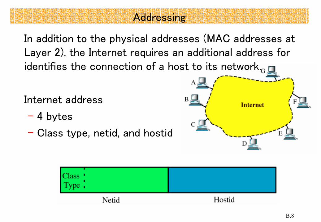
Sliding window
– the sender can transmit several frames before needing an acknowledgment.
– More efficient.

B.64
Flow Control (4)
– The sliding window refers to imaginary boxes at both the sender and the receiver.
– This window can hold frames at either end and provides the upper limit on the number of frame that can be transmitted before requiring acknowledgment.
– Frames may be acknowledged at any point without waiting for the window to fill up and may be transmitted as long as the window is not yet full.

B.65
Flow Control (4)
– For window size n, the frames are numbered 0,1,2,3,…,n-2,n-1,0,1,2,…
– Example n=7

B.66
Flow Control (5)
Sender window
– As frames are sent out, the left boundary of the window moves inward, shrinking the size of the window.
– Once an ACK arrives, the window expands.

B.67
Flow Control (6)
Receiver window
– As new frames come in, the size of the receiver window shrinks.
– As soon as an acknowledgment is sent, the window expands.

B.68
Flow Control (7)
Example