TCMC Physicians Lounge
281
TCMC PHYSICIANS LOUNGE Tri-City Medical Center 4002 Vista Way Oceanside, California 92056 SPECIFICATIONS SA PROJECT NO. 01657.00 04/07/17 S F E I R A R C H I T E C T S, INC. 1350 Columbia Street, Suite 603 San Diego, California 92101 P: 619 299 3917 F: 619 299 5084 www.sfeirarch.com
Transcript of TCMC Physicians Lounge

TCMC PHYSICIANS LOUNGE
Tr i -Ci ty Medical Center
4002 Vista Way Oceanside, California 92056
SPECIFICATIONS SA PROJECT NO. 01657.00
04/07/17
S F E I R A R C H I T E C T S, INC.
1350 Columbia Street, Suite 603
San Diego, California 92101
P: 619 299 3917 F: 619 299 5084
www.sfeirarch.com


TCMC Physicians Lounge Tri-City Medical Center PROJECT DIRECTORY SA Project No. 01657.00 00 01 03 - 1
PROJECT DIRECTORY TCMC PHYSICIANS LOUNGE TRI-CITY MEDICAL CENTER OCEANSIDE, CALIFORNIA 92056 Tri-City Healthcare District Owner 4002 Vista Way Oceanside, California 92056 Tel: 760.940.7709 Fax: 760.940.3435 S F E I R Architects Architect 1350 Columbia Street, Suite 603 San Diego, California 92101 Tel: 619.299.3917 Fax: 619.299.5084 Contacts: Joseph Sfeir – [email protected]
P2S Engineering, Inc. Plumbing and Electrical Engineer 9665 Chesapeake Drive, Suite 230 San Diego, California 92123 Tel: 619.618-2347 Fax: 619.330.0668 Contact: Paul Luster - [email protected]
Isley Design + Planning Interior Designer 1982 Palsero Avenue Escondido, California 92029 Tel: 760.484.0455
Specifications Consultants, Inc. Specifications Consultant PO Box 3010 Colorado Springs, Colorado 80934 Tel: 719.577.9414 Fax: 719.623.0172 Contact: Paul DeArment - [email protected]
END OF PROJECT DIRECTORY


Joseph Sfeir


TCMC Physicians Lounge Tri-City Medical Center TABLE OF CONTENTS SA Project No. 01657.00 00 01 10 - 1
TCMC PHYSICIANS LOUNGE TRI-CITY MEDICAL CENTER
4002 VISTA WAY OCEANSIDE, CALIFORNIA 92056
SPECIFICATIONS
04/07/17
TABLE OF CONTENTS
SPECIFICATIONS GROUP
GENERAL REQUIREMENTS SUBGROUP:
DIVISION 01 GENERAL REQUIREMENTS 01 10 00 Summary 1-4 01 22 00 Unit Prices 1 01 25 00 Substitution Procedures 1-2 01 26 00 Contract Modification Procedures 1-2 01 29 00 Payment Procedures 1-4 01 31 13 Project Coordination 1-2 01 31 19 Project Meetings 1-2 01 33 00 Submittal Procedures 1-6 01 35 16 Alteration Project Procedures 1-4 01 41 00 Regulatory Requirements 1-2 01 42 00 References 1-4 01 45 20 Quality Control Services 1-3 01 50 00 Temporary Facilities and Controls 1-4 01 60 00 Product Requirements 1-3 01 61 65 Low-Emitting Material Requirements 1-4 01 64 00 Owner-Furnished Products 1-2 01 71 16 Acceptance of Conditions 1-2 01 73 19 Installation 1-2 01 73 29 Cutting and Patching 1-2 01 77 00 Closeout Procedures 1-4 01 78 36 Warranties 1-2
FACILITY CONSTRUCTION SUBGROUP:
DIVISION 02 EXISTING CONDITIONS 02 41 19.16 Selective Interior Demolition 1-5 02 42 00 Removal and Salvage of Construction Materials 1-2
DIVISION 03 CONCRETE - Not Used
DIVISION 04 MASONRY - Not Used
DIVISION 05 METALS 05 05 19 Post-Installed Concrete Anchors 1-5 05 40 00 Cold-Formed Metal Framing 1-2 05 50 00 Metal Fabrications 1-3

TCMC Physicians Lounge Tri-City Medical Center TABLE OF CONTENTS SA Project No. 01657.00 00 01 10 - 2
DIVISION 06 WOOD, PLASTICS AND COMPOSITES 06 10 53 Miscellaneous Rough Carpentry 1-3 06 41 00 Architectural Wood Casework 1-9 06 42 19 Plastic-Laminate-Faced Wood Paneling 1-4
DIVISION 07 THERMAL AND MOISTURE PROTECTION 07 92 00 Joint Sealants 1-5
DIVISION 08 OPENINGS - Not Used
DIVISION 09 FINISHES 09 05 61 Common Work Results for Flooring Preparation 1-9 09 21 16 Gypsum Board Assemblies 1-10 09 30 00 Tiling 1-13 09 65 13 Resilient Base and Accessories 1-3 09 65 16 Resilient Sheet Flooring 1-5 09 65 19 Resilient Tile Flooring 1-6 09 68 00 Carpeting 1-5 09 91 23 Interior Painting 1-6
DIVISION 10 SPECIALTIES 10 26 13 Corner Guards 1-2 10 26 16.23 Chair Rails 1-4 10 26 23 Protective Wall Covering 1-3 10 28 13 Toilet Accessories 1-2
DIVISION 11 EQUIPMENT 11 00 00 Equipment 1-3
DIVISION 12 FURNISHINGS 12 36 61 Simulated Stone Countertops 1-5
DIVISION 13 SPECIAL CONSTRUCTION - Not Used
DIVISION 14 CONVEYING EQUIPMENT - Not Used
DIVISIONS 15 TO 19 - Reserved
FACILITY SERVICES SUBGROUP:
DIVISION 20 - Reserved
DIVISION 21 FIRE SUPPRESSION - Not Used
DIVISION 22 PLUMBING - Not Used
DIVISION 23 HEATING, VENTILATING, AND AIR CONDITIONING (HVAC) - Not Used
DIVISION 24 - Reserved
DIVISION 25 INTEGRATED AUTOMATION - Not Used
DIVISION 26 ELECTRICAL 26 00 10 Electrical General Provisions 1-9

TCMC Physicians Lounge Tri-City Medical Center TABLE OF CONTENTS SA Project No. 01657.00 00 01 10 - 3
26 05 00 Common Work Results For Electrical 1-4 26 05 19 Low-Voltage Electrical Power Conductors And Cables 1-5 26 05 26 Grounding And Bonding For Electrical Systems 1-4 26 05 29 Hangers And Supports For Electrical Systems 1-4 26 05 33 Raceway And Boxes For Electrical Systems 1-17 26 05 53 Identification For Electrical Systems 1-3 26 27 26 Wiring Devices 1-6 26 57 00 Medical Facilities 1
DIVISION 27 COMMUNICATIONS - Not Used
DIVISION 28 ELECTRONIC SAFETY AND SECURITY - Not Used
DIVISION 29 - Reserved
SITE AND INFRASTRUCTURE SUBGROUP:
DIVISIONS 30 TO 39 - Not Used
PROCESS EQUIPMENT SUBGROUP:
DIVISIONS 40 TO 49 - Not Used
APPENDICES
Appendix 1 - Equipment Cut Sheets
END OF TABLE OF CONTENTS


DIV
ISIO
N 0
1 –
GEN
ERA
L R
EQU
IREM
ENTS


TCMC Physicians Lounge Tri-City Medical Center SUMMARY SA Project No. 01657.00 01 10 00- 1
SECTION 01 10 00
SUMMARY PART 1 GENERAL 1.01 GENERAL REQUIREMENTS A. Division 01 - General Requirements relates to and expands upon the Conditions of the Contract,
including the General Conditions and the Supplementary Conditions, but does not supersede requirements specified in those documents or in the Owner/Contractor Agreement.
B. Division 01 - General Requirements governs work under all other divisions of the Specifications,
including Project Specifications issued under separate cover, and the Drawings. 1.02 PROJECT IDENTIFICATION AND PRINCIPAL ENTITIES A. Project Identification and Location:
TCMC Physicians Lounge Tri-City Medical Center 4002 Vista Way Oceanside, California 92056
B. Owner: Wherever the word “Owner” is used in this Project Manual, it shall mean:
Tri-City Healthcare District 4002 Vista Way Oceanside, California 92056
C. Architect: Wherever the word “Architect” is used in this Project Manual, it shall mean:
S F E I R Architects 1350 Columbia Street, Suite 603 San Diego, California 92101
D. General Contractor: Wherever the words “Contractor” or “General Contractor” are used in this
Project Manual, they shall mean the contractor who is party to the Owner/Contractor Agreement. 1.03 WORK COVERED BY CONTRACT DOCUMENTS A. Single Contract: Unless otherwise indicated or specified, all Work indicated on the Drawings and
described in the Specifications is to be executed under one prime contract between Owner and General Contractor.
B. Scope of Work: The Work consists of renovation of the existing Physicians Lounge and
Anesthesia Room on the first floor of the TCMC facility. It includes replacing finishes, cabinets, sink(s), and the addition of a new TV cabinet.
C. The locations of all existing utilities, as indicated on the Drawings, are approximate. General Contractor shall be responsible for verifying location of all underground and above ground utilities indicated on the Architectural, Mechanical, and Electrical Drawings prior to construction. Any damage to these utilities shall be the Contractor’s responsibility and they shall be repaired at no cost to the Owner.

TCMC Physicians Lounge Tri-City Medical Center SUMMARY SA Project No. 01657.00 01 10 00- 2
D. Failure to Visit Site: Will not relieve Contractor from necessity of furnishing materials or performing work that may be required to complete the Work in accordance with Drawings and Specifications without additional cost to Owner.
1.04 WORK BY OWNER OR UNDER SEPARATE CONTRACT A. Work by Others to be Executed During or After Completion of this Contract: 1. Remediation of Hazardous Materials: No information is available regarding possible
hazardous materials in the structures designated for demolition or the areas designated for remodeling. If hazardous materials, such as asbestos or lead-based paints, are encountered, remediation of such materials will be performed by others under separate contract to the Owner. Immediately notify Owner if such materials are observed before or during demolition operations. Coordinate with Owner to reschedule demolition and construction work to be completed after hazardous material remediation is accomplished.
2. Other items indicated to be by Owner, OFOI, or not in contract (N.I.C.) on Drawings. 1.05 COORDINATION WITH OCCUPANTS A. Owner Occupancy: Owner will occupy the premises during entire construction period, with the
exception of areas under construction. Cooperate with Owner during construction operations to minimize conflicts and facilitate Owner usage. Perform the Work so as not to interfere with Owner's operations. Maintain existing exits, unless otherwise indicated.
1. Maintain access to existing walkways, corridors, and other adjacent occupied or used facilities. Do not close or obstruct walkways, corridors, or other occupied or used facilities without written permission from Owner and authorities having jurisdiction.
a. Emergency Exits: Maintain all required fire exits from existing building at all times existing building is occupied during construction process.
b. Exit Doors, Stairways and Discharge Areas: Acceptable to local code authority. 2. Take precautions to allow for continued medical center operations including employee and
public access. 3. Related Requirements: See Section 01 35 16 Alteration Project Procedures. B. Disruptive Operations: Noisy and disruptive operations (such use of jack hammers and other
noisy equipment) shall not be allowed within existing building without prior authorization by the Owner.
1. Schedule and coordinate such operations with Owner so that they occur at least disruptive times.
2. Upon notification from Owner, cease operations which are, in opinion of Owner, disruptive to occupants.
C. Existing Utility Interruptions: Do not interrupt utilities serving facilities occupied by Owner or
others unless permitted under the following conditions and then only after arranging to provide temporary utility services according to requirements indicated:
1. Notify Owner not less than two days in advance of proposed utility interruptions. 2. Do not proceed with utility interruptions without Owner's written permission. 3. In general outages shall be scheduled at times when the building is not being utilized by
occupants. D. Provide not less than 72 hours' notice to Owner of activities that will affect Owner's operations. E. Construction Parking: Parking for construction labor on site shall be coordinated with the Owner.
F. No smoking or use of tobacco products anywhere on Owner’s property shall be allowed.

TCMC Physicians Lounge Tri-City Medical Center SUMMARY SA Project No. 01657.00 01 10 00- 3
1.06 USE OF SITE
A. General: Contractor shall have limited use of premises for construction operations as indicated on Drawings by the Contract limits and as defined at the Pre-construction Conference.
B. Limit use of premises to areas within the Contract limits indicated. Do not disturb portions of
building or Project site beyond areas in which the Work is indicated. 1. Owner Occupancy: Restrict access to extent required to allow for on-going occupancy of
portions of the building outside the area of work. 2. Driveways and Entrances: Keep driveways and entrances serving premises clear and
available to Owner, Owner's employees, and emergency vehicles at all times. Do not use these areas for parking or storage of materials.
a. Schedule deliveries to minimize use of driveways and entrances. b. Schedule deliveries to minimize space and time requirements for storage of materials
and equipment on-site. C. Use of Existing Building: Maintain existing building in a weathertight condition throughout
construction period. Repair damage caused by construction operations. Protect building and its occupants during construction period.
1. Related Requirements: a. Section 01 35 16 Alteration Project Procedures. b. Section 01 50 00 Temporary Facilities and Controls. D. On-Site Work Hours: Work shall be generally performed inside the existing building during
normal business working hours, Monday through Friday, unless specifically authorized by the Owner’s Representative.
1.07 WORK SEQUENCE AND CONSTRUCTION PHASING A. Sequencing of Construction Plan: Before start of construction on site, submit three copies of
construction plan regarding access to work; use of site; and scheduling and phasing of new, demolition and renovation work for acceptance by Owner and Architect. After acceptance of plan, construction sequencing shall comply with accepted plan unless deviations are accepted in writing.
1. No work may commence until Notice to Proceed is provided by the Owner.
1.08 PROJECT MANUAL FORMATS AND CONVENTIONS
A. MasterFormat: This Project Manual is organized on the basis of the 2016 Edition of the Construction Specifications Institute (CSI) MasterFormat.
1. The system of groups, subgroups and Divisions are listed in the Table of Contents of this Project Manual. It consists of 50 Divisions, Division 00 though Division 49, some of which are not used or are reserved for future expansion of the MasterFormat.
B. Specification Language: These Specifications are of abbreviated, simplified or streamlined type
and include incomplete sentences. 1. Omissions of words or phrases such as "the contractor shall", "in conformity therewith",
"shall be", "as noted on the Drawings", "a", "the", are intentional. 2. Supply omitted words or phrases by inference. 3. Supply words "shall be" or "shall" by inference when colon is used within sentences or
phrases. 4. Supply words "on the Drawings" by inference when "as indicated" is used with sentences or
phrases.

TCMC Physicians Lounge Tri-City Medical Center SUMMARY SA Project No. 01657.00 01 10 00- 4
PART 2 PRODUCTS - Not Used PART 3 EXECUTION - Not Used
END OF SECTION

TCMC Physicians Lounge Tri-City Medical Center UNIT PRICES SA Project No. 01657.00 01 22 00 - 1
SECTION 01 22 00
UNIT PRICES
PART 1 GENERAL
1.01 GENERAL A. Quantities indicated on the Drawings or extra quantities specified shall be included in the
Contractor's Base Bid. For ADDING or DEDUCTING from Base Bid quantities, the unit prices described in this section will be applied. The Contractor will be notified in writing of the quantities applicable to each unit price and Contract Price will be adjusted accordingly by change order.
B. All unit prices shall include all labor, materials, equipment, services, delivery to the Project,
overhead, profit, insurance and all other incidental expenses to complete the work specified. All work covered by unit prices shall be performed in accordance with requirements of the applicable sections of the specifications.
1.02 UNIT PRICES A. Unit Price for Vapor Emission Control Treatment of Floor Slabs: See Section 09 05 61 Common
Work Results for Flooring Preparation. 1. Unit of Measure: Square foot of floor slab area treated. 2. Bidding Requirements: Bidders shall indicate unit price for specified vapor emission control
treatment on their bid forms.
PART 2 PRODUCTS - Not Used
PART 3 EXECUTION - Not Used
END OF SECTION


TCMC Physicians Lounge Tri-City Medical Center SUBSTITUTION PROCEDURES SA Project No. 01657.00 01 25 00 - 1
SECTION 01 25 00
SUBSTITUTION PROCEDURES PART 1 GENERAL 1.01 SUMMARY A. Section Includes: 1. Administrative and procedural requirements for consideration of requests for substitution
during the construction phase of the Project. 2. Product substitution procedures. 3. Execution substitution procedures. B. Related Requirements: 1. General Conditions. 2. Product Requirements: Section 01 60 00. 1.02 LIMITATIONS ON SUBSTITUTIONS A. During Procurement Phase: Comply with Instructions to Bidders. B. During Construction Phase: Requests for substitutions of products will be considered only within
35 days after date of Owner-Contractor Agreement. Other requests will be considered only in case of product unavailability or other conditions beyond control of Contractor.
C. Substitutions: 1. Will not be considered when indicated on shop drawings or product data submittals without
separate formal request, when requested directly by subcontractor or supplier, or when acceptance will require substantial revision of Contract Documents.
2. Do not order or install substitute products without written acceptance. 3. Only one request for substitution for each product will be considered. When substitution is
not accepted provide specified product. 4. Architect will determine acceptability of substitutions. D. Value Engineering: For “value engineering” or similar cost or time reduction proposals that would
result in changes to the Drawings and Specifications, the Contractor shall follow procedures specified herein and any and all such changes are to be submitted in “Substitution Approval Request Form” provided by Architect upon request of the Contractor.
1.03 CONTRACTOR REPRESENTATION A. Request for Product Substitution: Representation that Contractor has investigated proposed
product and has determined that it is equal to or superior in all respects to specified product: 1. Contractor will provide same warranty for substitution as for specified product. 2. Contractor will coordinate installation of accepted substitute, making such changes as may
be required for work to be complete in all respects. 3. Contractor waives claims for additional costs related to substitution which may later become
apparent. B. Replacement: If substituted products do not meet or exceed above requirements, whether
before, during, or after incorporated into work, Contractor shall, at no additional cost to Owner, replace substituted products with products originally specified.

TCMC Physicians Lounge Tri-City Medical Center SUBSTITUTION PROCEDURES SA Project No. 01657.00 01 25 00 - 2
1.04 SUBSTITUTION REQUEST SUBMITTAL PROCEDURES A. Submittal : Submit two copies of each request. Submit separate request for each substitution. 1. Identify products by Specifications section and article numbers. 2. Provide manufacturer's name and address, trade name of products, and model or catalog
number. 3. List fabricators and suppliers as appropriate. B. Documentation: Document each request with complete data substantiating compliance of
proposed substitution with requirements of Contract Documents: 1. Attach Product Data as specified in Section 01 33 00. 2. Give itemized comparison of proposed substitution with specified product, listing variation,
and reference to specification section and article numbers. 3. Give quality and performance comparison between proposed substitution and specified
product. 4. List availability of maintenance services and replacement materials. 5. State effect of substitution on construction schedule, and changes required in other work or
products. 6. Reference UL Fire Resistance Directory design number if applicable. C. Architect: Will review Contractor's requests for substitutions with reasonable promptness. 1. If accepted by Architect, products proposed for substitution will be accepted subject to
modifications by manufacturer, if necessary, to meet detailed requirements of Drawings and Specifications.
2. Architect will not make exhaustive attempt to determine that products proposed for substitution are equal to, or can be modified in order to be equal to specified products.
D. Architect's Acceptance: Architect will notify Contractor, in writing, of decision to accept or reject
requested substitution. E. For Accepted Products: Submit shop drawings, product data, and samples in accordance with
Section 01 33 00. PART 2 PRODUCTS – Not Used PART 3 EXECUTION – Not Used
END OF SECTION

TCMC Physicians Lounge Tri-City Medical Center CONTRACT MODIFICATION PROCEDURES SA Project No. 01657.00 01 26 00 - 1
SECTION 01 26 00
CONTRACT MODIFICATION PROCEDURES PART 1 GENERAL 1.01 SUMMARY
A. This section specified administrative and procedural requirements necessary for handling and processing Contract modifications.
B. Related Sections: The following sections contain requirements that relate to this section:
1. Division 01 Section “Submittal Requirements” for requirements for the Contractor’s Construction Schedule.
2. Division 01 Section “Payment Procedures” for administrative procedures governing application for payment.
1.02 MINOR CHANGES IN THE WORK
A. Supplemental Instructions authorizing minor change in the Work, not involving an adjustment to the Contract Sum or Contract Time, may be issued by the Architect on an AIA form G711, Architect Supplemental Instructions.
1.03 CHANGE ORDER PROPOSAL REQUESTS
A. Owner-Initiated Proposal Request: Proposed changes in the Work that will require adjustment to
the Contract Sum or Contract Time will be issued by the Owner, with a detailed description of the proposed change and supplemental or revised Drawings and Specifications, if necessary. 1. Proposal requests issued by the Owner are for information only. Do not consider them
instruction either to stop work in progress, or to execute the proposed change. 2. Unless otherwise indicated in the proposal request, within 30 days of receipt of the proposal
request, submit to the Architect and the Owner for review an estimate of cost necessary to execute the proposed change. a. Include a list of quantities of products to be purchased and unit costs, along with the
total amount of purchases to me made. Where requested, furnish survey data to substantial quantities.
b. Indicate applicable taxes, delivery charges, equipment rental, and amounts of trade discounts.
c. Include a statement indicating the effect the proposed change in the Work will have on the Contract Time.
B. Contractor-Initiated Change Order Proposal Requests: When latent or other unforeseen
conditions require modifications to the Contract, the Contractor may propose changes by submitting a request for a change to the Owner and Architect. 1. Include a statement outlining the reasons for the change and the effect of the change on the
Work. Provide a complete description of the proposed change. Indicate the effect of the proposed change on the Contract Sum and Contract Time.
2. Include a list of the quantities of products to be purchased and unit costs along with the total amount of purchases to be made. Where requested, furnish survey data to substantiate quantities.
3. Indicate applicable taxes, delivery charges, equipment rental, and amounts of trade discounts.
4. Comply with requirements in Section ‘Products Substitutions “ if the proposed change in the work requires the substitutions of one product or system for a product or system specified.

TCMC Physicians Lounge Tri-City Medical Center CONTRACT MODIFICATION PROCEDURES SA Project No. 01657.00 01 26 00 - 2
C. Proposal Request Form: Use forms approved by the Owner for Change Order Proposals.
1.04 CHANGE ORDER PROCEDURES:
A. In addition to the procedure and information stated in the section, herein before: the Contractor shall follow Change Order procedures and information as stated in the General Conditions of the Contract and on the Bid Form.
B. Upon the Owner’s approval of a Change Order proposal Request, the owner will issue a Change
Order for signatures of the Owner, Contractor, and Architect.
C. OSHPD Approvals: In accordance with Part 1, Title 24, California Code of Regulations, all addenda and modifications to the Work requiring OSHPD approval shall be approved by the Office of Statewide Health Planning and Development (OSHPD) prior to proceeding with the work.
PART 2 PRODUCTS - Not Used PART 3 EXECUTION - Not Used
END OF SECTION

TCMC Physicians Lounge Tri-City Medical Center PAYMENT PROCEDURES SA Project No. 01657.00 01 29 00 - 1
SECTION 01 29 00
PAYMENT PROCEDURES PART 1 GENERAL 1.01 SUMMARY
A. This Section specifies administrative, and procedural requirements governing the Contractor’s Applications for Payment.
B. The Contractor’s Construction Schedule and Submittal Schedule are included in Section “
Submittals”. 1.02 COORDINATION
A. Coordinate preparation of the Schedule of Values with preparation of the Contractor’s Construction Schedule. 1. Correlate line items in the Schedule of Values with other required administrative schedules
and forms, including: a. Contractor’s construction schedule. b. Application for Payment form. c. List of subcontractors. d. Schedule of allowances. e. List of products. f. List of principal suppliers and fabricators. g. Schedule of submittals.
2. Submit the Schedule of Values- Schedule Amounts to the Owner at the earliest feasible date, but in no case later than 7 days before the date schedule for submittal of the initial Application for payment.
1.03 SCHEDULE OF VALUES
A. Identification; Include the following Project identification on the Schedule of Values: 1. Name of Owner. 2. Project name and location. 3. Name of Architect. 4. Project number. 5. Contractor’s name and address. 6. Date of submittal.
B. Arrange the Schedule of Values in a tabular form with separate columns to indicate the following
for each item listed; 1. Generic name. 2. Relate Specification Section. 3. Name OF subcontractor. 4. Name of manufacturer or fabricator. 5. Name of supplier. 6. Change Orders (numbers) that have affected value. 7. Dollar value. 8. Percentage of Contract Sum to the nearest one-hundredth percent, adjusted to total 100
percent.

TCMC Physicians Lounge Tri-City Medical Center PAYMENT PROCEDURES SA Project No. 01657.00 01 29 00 - 2
C. Provide a breakdown of the Contract Sum in sufficient detail to facilitate continued evaluation of Applications for Payment and progress evaluation of Applications fro Payment and progress report. Break principle subcontract amounts down into several line items.
D. Round amounts off to the nearest whole dollar; the total shall equal the Contract Sum. E. For each part of the Work where an Application for Payment may include materials or equipment,
purchased or fabricated and stored, but not yet installed, provide separate line items on the schedule of Values for initial cost of the materials, for each subsequent stage of completion, and for total installed value of that part of the work.
F. Margins of Cost: Show line items for indirect costs, and margins on actual costs, only to the
extent that such items will be listed individually and Applications for Payment. Each item in the Schedule of Values and Applications for Payment shall be completed including its total cost and proportionate share of general overhead and profit margin.
G. At the Contractor’s option, temporary facilities and other major cost items that are not direct cost
of actual work-in-place may be shown as separate line items in the Schedule of Values or distributed as general overhead expense.
H. Schedule Updating: Update and resubmit the Schedule of Values when change Orders result in
a change in the Contract sum.
1.04 APPLICATIONS FOR PAYMENT:
A. Each Application for payment shall be consistent with previous applications and payments ad certified by the Architect and paid for by the Owner. 1. The initial Application for payment, the Application fro payment at time of Substantial
Completion, and the final Application for Payment involved additional requirements.
B. Payment Application Times: The date for each progress payment is the first construction progress meeting of each month. The period of construction Work covered by each Application for Payment is the period ending at the last day of the month prior to the date for each progress payment and starting the day following the end of the preceding period.
C. Payment Applications Forms: Use AIA Document G702 and G703. D. Application Preparation: Complete every entry on the form, including notarization and execution
by person authorized to sign legal documents on behalf of the Owner. Incomplete applications will be returned without action. 1. Entries shall match data on the Schedule of Values and Contractor’s Construction Schedule.
Use updated schedule if revisions have been made. 2. Include amounts of Change Orders and Construction Change Directives issued prior to the
last day of the construction period covered by the application.
E. Transmittal: Submit 5 executed copies of each Application for payment to the Owner and Architect at the first of the bi-weekly Construction Progress Meeting. This meeting will extend into preview and acceptance by all required parties of the Contractors application of payment. 1. Transmit each copy with a transmittal form listing attachments, and recording appropriate
information related to the application in a manner acceptable to the Architect.

TCMC Physicians Lounge Tri-City Medical Center PAYMENT PROCEDURES SA Project No. 01657.00 01 29 00 - 3
F. Waivers of Mechanics Lien: With each Application for Payment submit waivers of Mechanic liens from subcontractors or sub-subcontractors and supplier for the construction period covered by the pervious application. 1. Submit partial waivers on each item for the amount requested, prior to deduction for
retainage, on each item. 2. When an application shows completion of an item, submit final or full waivers.
G. The Owner reserves the right to designate which entities involved in the Work must submit
waivers. 1. Wavier Delays: Submit each Application for Payment with the Contractors Wavier of
Mechanics lien for the period of construction covered by the application. 2. Submit final Application for payment with or proceeded by final wavier from every entity
involved with performance with Work covered by the Application who could lawfully be entitled to a lien.
3. Waiver Forms: Submit Wavier of lien of forms, and executed in a manner, acceptable to Owner.
H. Initial Application for payment: Administrative action and submittal that must precede or coincide
with submittal of the first Application for Payment include but not limited to the following: 1. List of subcontractors and their agreements with the Contractor. 2. List of principle suppliers and fabricators. 3. Schedule of Values. 4. Contractors Construction Schedule (preliminary if not final). 5. Schedule of principle products. 6. Submittal Schedule (preliminary if not final). 7. List of Contractor’s staff assignments. 8. List of Contractor’s principle consultants. 9. Copies of building permits. 10. Copies of authorization and licenses from governing authorities for performance of the Work. 11. Certificates of insurance and insurance policies. 12. Data needed to acquire Owner’s insurance.
I. Application for Payment at Substantial Completion: Following issuance of the Certificate of
Substantial Completion, on the entire project, submit an Application for Payment. J. Administrative actions and submittals that shall precede or coincide with this application include:
1. Occupancy permits and similar approvals. 2. Warranties (guarantees) and maintenance agreements. 3. Test/ adjust / balance records. 4. Maintenance instructions. 5. Changeover information related to owner’s occupancy, use, operation and maintenance. 6. Final cleaning. 7. Application for reduction of retainage, and consent of surety. 8. Advice on shifting insurance coverage. 9. Final progress photographs. 10. List of delayed work, recognized as exceptions to Architect’s Certificate of Substantial
Completion.
K. Final Payment Application: Administrative actions and submittals, which must precede or coincide with submittal of the final payment Application for Payment include the following: 1. Completion of project closeout requirements. 2. Completion of items specified for completion after Substantial Completion. 3. Assurance that unsettled claims will be settled. 4. Assurances that work not complete and accepted will complete without undo delay. 5. Transmittal of required Project Construction Records to the Owner.

TCMC Physicians Lounge Tri-City Medical Center PAYMENT PROCEDURES SA Project No. 01657.00 01 29 00 - 4
6. Proof that taxes, fees and similar obligations have been paid. 7. Removal of temporary facilities and services. 8. Removal of surplus materials, rubbish and similar elements.
PART 2 PRODUCTS - Not Used
PART 3 EXECUTION - Not Used
END OF SECTION

TCMC Physicians Lounge Tri-City Medical Center PROJECT COORDINATION SA Project No. 01657.00 01 31 13 - 1
SECTION 01 31 13
PROJECT COORDINATION PART 1 GENERAL 1.01 SUMMARY
A. This section specified administrative and supervisory requirements necessary for Project
coordination including, but necessary limited to: 1. Coordination. 2. Administrative and Supervisory personnel. 3. General installation provision. 4. Cleaning and protection. 5. Time and Manner.
B. Progress meetings, coordination meetings and pre-installation conferences are included in
Section “Project Meetings.” \1. Requirements for the Contractor’s Construction Schedule are included in Section
“Submittals.” 1.02 COORDINATION
A. Coordination: Coordinate construction activities included under various Sections of these Specifications to assure efficient and orderly installation of each part of the Work. Coordinate construction operations include under different Sections of the Specifications that are dependent upon each other for proper installation, connection, and operation. 1. Where installation of one part of the Work is dependent on installation of other components,
either before or after its own installation, schedule Construction activities in the sequence to obtain the best results.
2. Where availability of space is limited, coordinate installation of different components to assure maximum accessibility for required maintenance, service and repair.
1.03 COORDINATION
A. Make adequate provisions to accommodate items scheduled for later installation. B. Administrative Procedures: Coordinate scheduling and timing of required Administrative
Procedures with other constructions activities to avoid conflicts and ensure orderly progress of the work. Such administrative activities include, but are not limited to the following: 1. Preparation of Schedules. 2. Installation and removal of temporary facilities. 3. Delivery and processing of submittals. 4. Progress Meetings. 5. Project closeout activities.
C. Conservation: Coordinate Construction activities to ensure that operations are carried out with
considerations given to conservation of energy, water, and materials. 1. Salvage materials and equipment involved in performance of, but not actually incorporated
in, the Work. Refer to other sections for disposition of salvaged materials that are designated as Owner’s property.
PART 2 PRODUCTS - Not Used

TCMC Physicians Lounge Tri-City Medical Center PROJECT COORDINATION SA Project No. 01657.00 01 31 13 - 2
PART 3 EXECUTION 3.01 GENERAL INSTALLATION PROVISIONS
A. Inspection of Conditions: Require the Installer of each major component to inspect both the substrate and conditions under which Work is to be performed. Do not proceed until unsatisfactory conditions have been corrected in an acceptable manner.
B. Manufacturer’s Instructions: Comply with manufacturer’s installation instructions and
recommendations, to the extent that those instructions and recommendations are more explicit or stringent than requirements contained in Contract Documents.
C. Inspect materials or equipment immediately upon delivery and again prior to installation. Reject
damage and defective items. 3.02 GENERAL INSTALLATION PROVISIONS:
A. Provide attachment and connection devices and methods necessary for securing Work. Secure Work true to line and level. Allow for expansion and building movement.
B. Visual effects: Provide uniform joint widths in exposed Work. Arrange joints in exposed Work to
obtain the best visual effect. Refer questionable choices to the Architect for final decision. C. Recheck measurements and dimensions, before starting each installation. D. Coordinate temporary enclosures with required inspections and tests, to minimize the necessity
of uncovering completed construction for that purpose. E. Mounting Heights: Where mounting heights are not indicated, install individual components at
standard mounting heights recognized with the industry for the particular application indicated. Refer questionable mounting height decisions to the Architect for the final decision.
3.03 CLEANING AND PROTECTION
A. Cleaning and Maintenance: 1. Special cleaning requirements for specific units of Work are included in the appropriate
sections of the specifications. Final cleaning is required under section 01700. 2. The Contractor shall remove and dispose of all waste materials and rubbish due to all
construction operations under the contract.
B. Protection: In addition to the General Conditions, the Contractor or alteration work. Use only new materials in construction of all protection. If wood is called for, it shall be fire retardant treated wood if used within the interior of the building. No cutting of materials shall be done within occupied spaces.
3.04 OWNER OCCUPANCY:
A. Partial Owner Occupancy: The Owner reserves the right to place and install equipment as necessary in completed areas of the building and to occupy such completed areas prior to substantial completion, provided that such occupancy does not substantially interfere with completion of the work. Such placing of equipment and partial occupancy shall not constitute acceptance of the work or any part of the work.
END OF SECTION

TCMC Physicians Lounge Tri-City Medical Center PROJECT MEETINGS SA Project No. 01657.00 01 31 19 - 1
SECTION 01 31 19
PROJECT MEETINGS PART 1 GENERAL 1.01 SUMMARY
A. This Section specifies administrative and procedural requirements for project meetings including but not limited to: 1. Pre-Construction Conference. 2. Pre-Installation Conferences. 3. Progress Meetings.
B. Construction schedules are specified in another Division-01 Section.
1.02 PRE-CONSTRUCTION CONFERENCE
A. Schedule a pre-construction conference and organizational meeting at the Project site or other convenient location no later than 5 days after the notice to proceed and prior to commencement of construction activities. Conduct the meeting to review responsibilities and personnel assignments.
B. Attendees: The Owner, Architect and their consultants, the Prime Contractors and their
superintendent, major subcontractors, manufactures, suppliers and other concerned parties shall each be represented at the conference by persons familiar with and authorized to conclude matters relating to the Work.
C. Agenda: Discuss items of significance that could affect progress including but not limited to such
topics as: 1. Tentative construction schedule. 2. Critical Work sequencing. 3. Designation of responsible personnel. 4. Procedures for processing filed decisions and Change Orders. 5. Procedures for processing Applications for Payment. 6. Distribution of Contract Documents. 7. Submittal of Shop Drawings, Product Data and Samples. 8. Preparation of record documents. 9. Use of the premises. 10. Office, work and storage areas. 11. Equipment deliveries and priorities. 12. Safety procedure 13. First aid. 14. Security 15. Housekeeping. 16. Working Hours.
1.03 PRE-INSTALLATION CONFERENCES
A. Conduct a pre-installation conference at the site before each construction activity that requires coordination with other construction and as specified herein. The Installer and representatives of manufacturers and fabricators involved in or affected by the installation, and its coordination or integration with other materials and installations that have preceded or will follow, shall attend the meeting. Advise the Architect of Schedule meeting dates.
TCMC Physicians Lounge Tri-City Medical Center PROJECT MEETINGS SA Project No. 01657.00 01 31 19 - 2
B. Review the progress of other construction activities and preparations for the particular activity under consideration at each pre-installation conference.
C. Do not proceed if the conference cannot be successfully concluded. Indicate whatever actions
are necessary to resolve impediments to performance of Work and reconvene the conference at the earliest feasible date.
1.04 PROGRESS MEETINGS
A. Conduct progress meetings at Project site bi-weekly. Coordinate dates of meeting with preparation of the payment request.
B. Attendees: In addition to representative of the Owner and Architect, each subcontractor, supplier
or other entity concerned with current progress or involved in planning, coordination or performance of future activities shall be represented at these meetings by persons familiar with the Project and authorized to conclude matters relating to progress.
C. Agenda: Review and correct or approve minutes of the previous progress meeting. Review other
items of significance that could affect progress. Include topics for discussion as appropriate to the current of the Project. 1. Contractor’s Construction Schedule: Review progress since the last meeting. Determine
where each activity is in relation to the Contractor’s Construction Schedule, whether on time or ahead or behind schedule. Determine how construction behind schedule will be expedited; secure commitments from parties involved to do so. Discuss schedule revisions are required to ensure that current and subsequent activities will be completed within the Contract Time.
2. Schedule Updating: Revise the construction schedule after each progress meeting where revisions to the schedule have been made or recognized. Issue the revise schedule to the Owner and Architect.
PART 2 PRODUCTS – Not used PART 3 EXECUTION – Not used
END OF SECTION

TCMC Physicians Lounge Tri-City Medical Center SUBMITTAL PROCEDURES SA Project No. 01657.00 01 33 00 - 1
SECTION 01 33 00
SUBMITTAL PROCEDURES PART 1 GENERAL 1.01 SUMMARY
A. This Section specifies administrative and procedural requirements for submittals required for performance of the Work, including: 1. Contractor’s construction schedule. 2. Submittal schedule. 3. Construction progress photographs. 4. Shop Drawings. 5. Product Data. 6. Samples.
B. Administrative Submittals: T=Refer to other Division-1 Sections and other Contract Documents
for requirements for administrative submittals. Such submittals include, but are not limited to: 1. Permits. 2. Applications for payment. 3. Performance and payment bonds. 4. Insurance certificates. 5. List of Subcontractors.
C. The schedule of Values submittal is included in Section “Applications for Payment.”’ D. Inspection and test reports are included in Section “Quality Control Services.”
1.02 SUBMITTAL PROCEDURES
A. Coordination: Coordinate preparation and processing of submittals with performance of construction activities. Transmit each submittal sufficiently in advance of performance of related construction activities to avoid delays. 1. Coordinate each submittal with fabricate, purchasing, testing, delivery, other submittals and
related activities that require sequential activities. 2. Coordinate transmittal of different types of submittals for related elements of the Work so
processing will not be delayed by the need to review submittals constructed for coordination. a. The Architect reserves the right to withhold action on a submittal requiring coordination
with other submittals until related submittals are received.
B. Processing: Allow sufficient review time so that installation will not be delayed as result of the time required to process submittals, including time for resubmittals. 1. Allow two weeks for initial review. Allow Additional time if processing must be delayed to
permit coordination with subsequent submittals. The Architect will promptly advise the contractor when a submittal being processed must be delayed for coordination.
2. If an intermediate submittal is necessary, process the same as initial submittal. 3. Allow two weeks for reprocessing each submittal. 4. No extension of Contract Time will be authorized because of failure to transmit submittals to
the Architect sufficiently in advance of the work to permit processing.

TCMC Physicians Lounge Tri-City Medical Center SUBMITTAL PROCEDURES SA Project No. 01657.00 01 33 00 - 2
C. Submittal Preparation: Place a permanent label or title block on each submittal for identification. Indicate the name of the entity that prepared each submittal on the label or title block. 1. Provide a space approximately 4” x 5” on the label or beside the title block on Shop
Drawings and product Data to record the Contractor’s review and approval markings and the action taken for accuracy, completeness and compliance with the Contract Documents. Submittals without evidence of the Contractor’s review and approval will be returned for resubmission.
2. Include the following information on the label for processing and recording action taken. a. Project name. b. Date. c. Name and address of Architect. d. Name and address of Contractor. e. Name and address of subcontractor. f. Name and address of supplier. g. Name manufacturer. h. Number and title of appropriate Specifications Section. i. Drawings number and detail references, as appropriate.
D. Submittal Transmittal: Package each submittal appropriately for transmittal and handling.
Transmit each submittal from Contractor to Architect using a transmittal form with copy of transmittal to Owner. Submittal received from sources other than the Contractor will be returned without action. 1. On the transmittal Record relevant information and requests for data. On the form, or
separate sheet, record deviations from Contract Document requirement, including minor variations and limitations. Include Contractor’s certification that information complies with Contract Document requirements.
1.03 CONTRACTORS’ CONSTRUCTION SCHEDULE
A. Bar-Chart Schedule: The General Contractor shall prepare a fully developed, horizontal bar-chart type contractors’ construction schedule. Submit within 10 days of the date of the notice to proceed. 1. Provide a separate time bar for each significant construction activity including the related
contracts activities. Provide a continuous vertical line to identify the first working day of each week. Use the same breakdown of units of the work as indicate in the “Schedule of Values.”
2. Within each time bar indicated estimate completion percentage in 10 percent increments. As Work progress, place a contrasting mark in each bar to indicate Actual Completion.
3. Prepare the schedule on a sheet, or series of sheets, of stable transparency, or other reproducible media, of sufficient width to show data for the entire construction period.
4. Secure time commitments for performing critical elements of the Work from parties involved. Coordinate each element on the schedule with other construction activities; include minor elements involved in the sequence of the Work. Show each activity in proper sequence. Indicate graphically sequences necessary for completion of related portions of the Work.
5. Coordinate the Contractors’ construction schedule with the schedule of values, list of subcontracts, submittal schedule, progress reports, payment requests and other schedule.
6. Indicate completion in advance of the date established for schedule Completion. Indicate Substantial Completion on the schedule to allow time for the Architect’s procedures necessary for certification of Substantial Completion.
B. Distribution: Following response to the initial submittal, print and distribute copies to the
Architect, Owner, related Prime Contractor, subcontractors, and other parties require to comply with schedule dates. Post copies in the project meeting room and temporary field office. 1. When revisions are made, distribute to the same parties and post in the same locations.
Delete parties from distribution when they have completed their assigned portion of the Work and are no longer involved in construction activities.

TCMC Physicians Lounge Tri-City Medical Center SUBMITTAL PROCEDURES SA Project No. 01657.00 01 33 00 - 3
C. Schedule Updating: Revise and reissue the schedule after each meeting or activity, where revisions have been recognized or made.
1.04 SUBMITTAL SCHEDULE
A. After development and acceptance of the Contractors’ construction schedule, each Prime Contractor shall prepare a complete schedule of submittals. Submit the schedule within 10 days from the Pre-Construction Conference.
B. Coordinate submittal schedule with the list of subcontracts, schedule of values and the list of
products as well as the Contractor’s construction schedule. C. Prepare the schedule in chronological order; include submittals required during the first 30 days
of Construction. Provide the following information: 1. Schedule date for the first submittal. 2. Related Section number. 3. Submittal category. 4. Name of subcontractor. 5. Description of the part of the work covered. 6. Scheduled date for resubmittal. 7. Scheduled date for the Architect’s final release or approval.
D. Distribution: Following response to initial submittal, print and distribute copies to the Architect’s,
Owner, subcontractors, and other parties required to comply with submittal date indicated. Post copies in the Project meeting room and file in office. 1. When revisions are made, distribute to the same parties and post in the same locations.
Delete parties from distribution when they have completed their assigned portion of the Work and are no longer involved in construction activities.
E. Schedule Updating: Revise and reissue the schedule after each meeting or activities, where
revisions have been recognized or made. 1.05 SHOP DRAWINGS
A. Submit newly prepared information, drawn to accurate scale. Highlight, encircle, or otherwise indicate deviations from the Contract Documents. Do not reproduce Contract Documents or copy standard information as the basis of shop Drawings. Standard information prepared without specific reference to the Project is not considered Shop Drawings.
B. Shop Drawings include fabrication and installation drawings, setting diagrams, schedules,
patterns, templates and similar drawings. Include the following information: 1. Dimensions. 2. Identification of products and materials included. 3. Completion with specified standards. 4. Notation of coordination requirements. 5. Notation of dimensions established field measurement.
C. Sheet Size: Except for templates, patterns and similar full-size Drawings, submit Shop Drawings
on sheets at least 8-1/2”x11” but not larger than 30” x 42” D. Initial Submittal: To Architect submit one correctable translucent reproducible print and one blue-
or black-line print for the Architect’s review; the reproducible print will be returned.

TCMC Physicians Lounge Tri-City Medical Center SUBMITTAL PROCEDURES SA Project No. 01657.00 01 33 00 - 4
E. Final Submittal: To Architect a minimum of blue- or black-line prints; submit 8 prints where required for maintenance manuals. 5 prints will be retained; the remainder will be returned. 1. One of the prints returned shall be marked-up and maintained as a “Record Document”. 2. Do not Shop drawings without an appropriate final stamp indicating action taken in
connection with construction.
1.06 PRODUCT DATA
A. Collect product Data into a single submittal for each element of construction or system. Product Data included printed information such as manufacturer’s installation instructions, catalog cuts, standard color charts, roughing-in diagrams and templates, standard wiring diagrams and performance curves. Where Product Data must be specially prepared because standard printed data is not suitable for use, submit as ‘ Shop Drawings”.
B. Mark each copy to show applicable choices and options. Where printed Product Data included
information on several products, some of which are not required. Mark copies to indicate the applicable information. Include the following information: 1. Manufacturer’s printed recommendations. 2. Compliance with recognized trade association standards. 3. Compliance with recognized testing agency standards. 4. Application of testing agency labels and seals. 5. Notation of dimensions verified by field measurement. 6. Notation of coordination requirements.
C. Do not submit Product Data until compliance with requirements of the Contract Documents has
been confirmed. D. Preliminary Submittal: To Architect submit a preliminary single-copy of product Data where
selection of options is required. E. Submittals: To Architect submit a minimum of 7 copies of each required submittal; submit 8
copies where required for maintenance manuals. The Architect will retain 5 copies. And will return the other marked with action taken and corrections or modifications required.
F. Distribution: Furnish copies of final submittal to installers, subcontractors, suppliers,
manufacturers, fabricators, and other required for performance of construction activities. Show distribution on transmittal form with copy being sent to Architect and Owner.
1.07 SAMPLES
A. Submit to Architect full-size, fully fabricate Sample cured and finished as specified and physically identical with the material or product proposed. Samples include partial sections of manufactured or fabricate components, cuts or containers of materials; color ranges sets, and swatches showing color, texture and pattern.
B. Mount, display, or package Samples in the manner specified to facilitate review of qualities
indicated. Prepare Samples to match the Architect’s Sample. Include the following: 1. Generic description of the Sample. 2. Sample source. 3. Product name or name of manufacturer. 4. Compliance with recognized standards. 5. Availability and delivery time.

TCMC Physicians Lounge Tri-City Medical Center SUBMITTAL PROCEDURES SA Project No. 01657.00 01 33 00 - 5
C. Submit to Architect Samples for review of kind, color, pattern, and texture, for a final check of these characteristics with other elements, and for a comparison of these characteristic between the final submittal and the actual component as delivered and installed. 1. Where variation in color, pattern, texture or other characteristic are inherent in the material or
product represented, submit multiple units (not less than 3), that show approximate limits of the variations.
2. Refer to other Specification sections for requirements for Samples that illustrate workmanship. Fabrication techniques, details of assembly, connections, operation and similar construction characteristic.
3. Refer to other Sections for Samples to be returned to the Contractor for incorporation in the Work. Such Samples must be undamaged at time of use. On the transmittal of Sample submittals.
D. Preliminary submittals: Where Samples are for selection of color, pattern, texture or similar
characteristics from a range of standard choices, submit a full set of choices for the material or product. 1. Preliminary submittals will be reviewed and returned with the Architect’s mark indicating
selection and other action.
E. Submittals: Except for Samples illustrating assembly details, workmanship, fabrication techniques, connections, operation and similar characteristics, submit 3 sets; one will be returned marked with the action taken. 1. Maintain seats of Samples, as returned, at the Project site, for Quality comparisons
throughout the course of construction. 2. Unless no completion with Contract Document provisions is observed, the submittal may
serve as the final submittal. 3. Sample sets may be used to obtain final acceptance of the construction associate with each
set.
F. Distribution of Samples: Prepare and distribute additional sets to subcontractors, manufacturers, fabricators, supplies, installers, and others as required for performance of the work. Show distribution on transmittal form sent to Architect And Owner.
G. Filed Samples specified in individual Sections are special types of Samples. Field Samples are
full-size examples erected on site to illustrate finish coats, or finishing materials and to establish the standard by which the Work will be judge. 1. Comply with submittal requirements to the fullest extent possible. Process transmittal forms
to provide a record of activity. 1.08 ARCHITECT’S ACTION
A. Except for submittals for record, information or similar purposes, here action and return is required or requested, the Architect will review each submittal, mark to indicate action taken, and promptly. 1. Compliance with specified characteristics is the Contractor’s responsibility.
B. Action Stamp: The Architect will stamp each submittal with a uniform, self-explanatory action
stamp. The stamp will be appropriately marked, as follows, to indicate the action taken. 1. Final Unrestricted Release: Where submittals are marked “No Exception Taken,” that part of
the work covered by the submittal may proceed provided it complies with requirements of the Contract Documents; final acceptance will depend upon that compliance.
2. Final-but-Restricted Release: When submittals are marked “Make Corrections Noted,” that part of the work covered by the submittal may proceed provided it complies with notations or corrections on the submittal and requirements of the Contract Documents; final acceptance will depend upon that compliance.

TCMC Physicians Lounge Tri-City Medical Center SUBMITTAL PROCEDURES SA Project No. 01657.00 01 33 00 - 6
3. Returned for Resubmittal: When submittal is marked “Revise and Resubmit,” do not proceed with that part of the Work covered by the submittal, including purchasing, fabrication, delivery, or other activity. Revise or prepare a new submittal in accordance with the notations; resubmit without delay. Repeat if necessary to obtain a different action mark.
4. Do not permit submittals marked “Revise and Resubmit” to be used at the Project site, or elsewhere where Work is in progress.
5. Other Action: Where a submittal is primarily for information or record purposes, special processing or other activity, the submittal will be returned.
PART 2 PRODUCTS - Not Used
PART 3 EXECUTION - Not Used
END OF SECTION

TCMC Physicians Lounge Tri-City Medical Center ALTERATION PROJECT PROCEDURES SA Project No. 01657.00 01 35 16 - 1
SECTION 01 35 16
ALTERATION PROJECT PROCEDURES PART 1 GENERAL 1.01 REQUIREMENTS INCLUDED A. Coordinate work of trades and schedule elements of alterations and renovation work by
procedures and methods to expedite completion of the Work. B. In addition to demolition specified in Section 02 41 19.16 and that specifically shown, cut, move
and remove items as necessary to provide access or to allow alterations and new work to proceed. Include such items as:
1. Repair or removal of hazardous or unsanitary conditions. 2. Removal of abandoned items and items serving no useful purpose, such as abandoned
piping, conduit and wiring. 3. Removal of unsuitable or extraneous materials not marked for salvage, such as abandoned
furnishings and equipment, and debris such as rotted wood, rusted metals and deteriorated concrete.
4. Cleaning of surfaces, and removal of surface finishes, as needed to install new work and finishes.
C. Patch, repair and refinish existing items to remain, to the specified conditions for each material,
with a workmanlike transition to adjacent new items of construction. D. Coordination of power outages and major interruptions of progress of construction work with
Owner. 1.02 RELATED REQUIREMENTS A. Materials for Renovation Work: Specifications in Divisions 02 through 31. B. Use of Premises and Work Restrictions: Section 01 10 00 Summary. C. Cutting and Patching of New or Existing Work During Construction: Section 01 73 29 Cutting and
Patching. D. Use of Existing Utilities: Section 01 50 00 Temporary Facilities and Controls. E. Cleaning During Construction: Section 01 50 00 Temporary Facilities and Controls. F. Selective Interior Demolition: Section 02 41 19.16. 1.03 ALTERATIONS, CUTTING AND PROTECTION A. Assign the work of moving, removal, cutting and patching to trades qualified to perform the work
in a manner to cause least damage to each type of work, and provide means of returning surfaces to appearance of new work.
B. Perform cutting and removal work to remove minimum necessary, and in a manner to avoid damage to adjacent work.
1. Cut finish surfaces such as masonry, tile, stone flooring, plaster or metals by methods to terminate surfaces in a straight line at a natural point of division.

TCMC Physicians Lounge Tri-City Medical Center ALTERATION PROJECT PROCEDURES SA Project No. 01657.00 01 35 16 - 2
C. Protect existing finishes, equipment and, adjacent work that is scheduled to remain, from damage. 1. Protect existing and new work from weather and extremes of temperature.
a. Maintain existing interior work above 60 degrees F. b. Provide weather protection, waterproofing, heat and humidity control as needed to
prevent damage to remaining existing work and to new work. D. Temporary Enclosures: 1. Provide temporary, dustproof enclosures to separate work areas from existing building and
from areas occupied by Owner. 1.04 COORDINATION WITH OWNER'S USE OF THE FACILITY A. General: Coordinate construction phasing with operation of Owner's existing facility. The Owner
intends to occupy portions of the existing building throughout construction. 1. Establish effective communications with the Owner regarding Owner’s operation and moving
schedule. Give as much advance notice as possible, in addition to the minimums specified, for construction activities that will affect Owner's operations.
B. Utility Interruptions: Coordinate with Owner. Notify Owner 48 hours in advance of all necessary
utility interruptions, including those scheduled for off hours. C. Sequence of Construction and Remodeling: 1. Coordination: Coordinate construction schedule with Owner's requirements.
2. Phasing: See Phasing Plan and Phasing Notes on Drawings. PART 2 PRODUCTS 2.01 PRODUCTS FOR PATCHING, EXTENDING AND MATCHING A. General Requirements that Work be Complete: 1. Provide same products or types of construction as that in existing structure, as needed to
patch, extend or match existing work. a. Generally Contract Documents will not define products or standards of workmanship
present in existing construction; Contractor shall determine products by inspection and any necessary testing, and workmanship by use of the existing as a sample of comparison.
2. Presence of a product, finish, or type of construction, requires that patching, extending or matching shall be performed as necessary to make work complete and consistent.
PART 3 EXECUTION 3.01 LAYING OUT WORK A. Verify dimensions and elevations indicated in layout of existing work. Refer discrepancies
between Drawings, Specifications and existing conditions to Architect for adjustment before work affected is performed. Failure to make such notification shall place responsibility upon Contractor to carry out work in satisfactory, workmanlike manner.
B. The Contractor shall be held responsible for the location and elevation of the construction
contemplated by the Construction Documents.

TCMC Physicians Lounge Tri-City Medical Center ALTERATION PROJECT PROCEDURES SA Project No. 01657.00 01 35 16 - 3
C. Prior to commencing work, carefully compare and check Architectural, Structural, Mechanical and Electrical Drawings, each with the other that in any way affects the location or elevation of the work to be executed, and should any discrepancy be found, immediately report the same to the Architect for verification and adjustment.
3.02 LOCATION OF EQUIPMENT AND PIPING A. Drawings showing location of equipment, piping, ductwork, etc. are diagrammatic and job
conditions shall not always duplicate conditions shown. When this situation occurs, it shall be brought to the Architect's attention immediately and the relocation determined in a joint conference.
3.03 PATCHING EXISTING FACILITIES A. Existing structures, facilities, etc. that are damaged or removed due to required construction
work, shall be patched, repaired or replaced, and be left in their original state of repair by the Contractor, to satisfaction of the Architect.
3.04 INTEGRATING EXISTING WORK A. Protect existing improvements from damage. B. Contractor's operations shall be confined to the immediate vicinity of the new work and shall not
in any way interfere with or obstruct the ingress or egress to and from adjacent facilities. C. Where new work is to be connected to existing work, special care shall be exercised not to
disturb or damage the existing work more than necessary. All damaged work shall be replaced, repaired and restored to its original condition at no cost to the Owner.
3.05 ADJUSTING A. Where partitions are removed, patch floors, walls and ceilings with finish materials to match
existing. 1. Where removal of partitions results in adjacent spaces becoming one, rework floors and
ceilings to provide smooth planes without breaks, steps or bulkheads. 2. Where extreme change of plane occurs, request instructions from Architect as to method of
making transition. B. Trim and refinish existing doors as necessary to clear new floors. 3.06 DAMAGED SURFACES A. Patch and replace any portion of an existing finished surface which is found to be damaged,
lifted, discolored, or shows other imperfections, with matching material. 1. Provide adequate support of substrate prior to patching the finish. 2. Refinish patched portions of painted or coated surfaces in a manner to produce uniform
color and texture over entire surface. 3. When existing surface finish cannot be matched, refinish entire surface to nearest
intersections.

TCMC Physicians Lounge Tri-City Medical Center ALTERATION PROJECT PROCEDURES SA Project No. 01657.00 01 35 16 - 4
3.07 TRANSITION FROM EXISTING TO NEW WORK
A. When new work abuts or finishes flush with existing work, make a smooth and workmanlike transition. Patch work shall match existing adjacent work in texture and appearance so that the patch or transition is invisible at a distance of five feet.
1. When finished surfaces are cut in such a way that a smooth transition with new work is not possible, terminate existing surface in a neat manner along a straight line at a natural line of division, and provide trim appropriate to finished surface.
3.08 DUST CONTROL A. Precaution shall be exercised at all times to control dust created as a result of any operations
during the construction period. If serious problems arise due to air borne dust, and when directed by Architect, operations causing such problems shall be temporarily discontinued and necessary steps taken to control the dust.
3.09 FIRE PROTECTION A. Maintain good housekeeping practices to reduce the risk of fire damage and injury to workmen.
All scrap materials, rubbish and trash shall be removed daily from in and about the work area and shall not be permitted to be scattered to adjacent areas.
B. Suitable storage space shall be provided outside the immediate building area for storing
flammable materials and paints; no storage will be permitted in the building. Excess flammable liquids being used inside the building shall be kept in closed metal container and removed from the building during unused periods.
C. A fire extinguisher shall be available at each location where cutting or welding is being performed.
Where electric or gas welding or cutting work is done, interposed shields of incombustible material shall be used to protect against fire damage due to sparks and hot metal. When temporary heating devices are used, a watchman shall be present to cover periods when other workmen are not on the premises.
D. Provide fire extinguishers in accordance with the recommendations of NFPA Bulletins Nos. 10
and 241. However, in all cases a minimum of four fire extinguishers shall be available for each building.
3.10 CLEANING A. Perform periodic and final cleaning as specified in Section 01 74 00, 01 50 00 and as follows: 1. Clean Owner-occupied areas where construction or remodeling is occurring, daily. 2. Clean areas of heavy dust production daily. 3. Clean spillage and overspray immediately. B. At completion of work of each trade, clean area and make surfaces ready for work of successive
trades. C. At completion of work in each area, provide final cleaning and return space to a condition suitable
for use by Owner.
END OF SECTION

TCMC Physicians Lounge Tri-City Medical Center REGULATORY REQUIREMENTS SA Project No. 01657.00 01 41 00 - 1
SECTION 01 41 00
REGULATORY REQUIREMENTS
PART 1 GENERAL
1.01 RELATED REQUIREMENTS
A. Code and Regulatory Requirements Data on Sheets A1-00 through A1-02 of the Drawings.
1.02 PERMITS AND FEES
A. Office of Statewide Health Planning and Development (OSHPD) Requirements: OSHPD is the primary agency having jurisdiction over project design and construction within healthcare facilities. 1. Licensed Contractors Declaration: Prepare and submit through Architect license documents
required for OSHPD approval. 2. Allow access to the Project site at any time to OSHPD designated Inspector of Record (IOR)
for the Project. 3. File OSHPD Verified Report forms every three months during construction. 4. Office of Statewide Health Planning and Development (OSHPD) Building Permit will be
obtained and paid for by Owner.
B. Permits, Licenses, and Certificates: See General Conditions. For Owner's records, submit copies of permits, licenses, certifications, inspection reports, releases, jurisdictional settlements, notices, receipts for fee payments, judgments, correspondence, records, and similar documents, established for compliance with environmental regulations bearing on performance of the Work.
1.03 CODES AND ORDINANCES
A. Compliance: All construction shall comply with all applicable codes, ordinances and regulations of federal, state, county, city, and special district agencies and jurisdictions having authority over the Project and in effect on the issue date of the Construction Documents: Applicable codes and regulations include, but are not necessarily limited to, the following:
California Code of Regulations (CCR), Title 8, Chapter 4, Subchapter 6, Elevator Safety Orders California Code of Regulations (CCR), Title 19, Public Safety California Code of Regulations (CCR), Title 22, Social Security California Code of Regulations (CCR), Title 24, Building Standards, Including, but not limited to:
Part 1 - 2016 California Building Standards Administrative Code (CAC) Part 2 - 2016 California Building Code (CBC) Part 3 - 2016 California Electrical Code (CEC) Part 4 - 2016 California Mechanical Code (CMC Part 5 - 2016 California Plumbing Code (CPC) Part 6 - 2016 California Energy Code Part 9 - 2016 California Fire Code (CFC) Part 10 - 2016 California Existing Building Code Part 11 - 2016 California Green Building Standards Code Part 12 - 2016 California Referenced Standards Code

TCMC Physicians Lounge Tri-City Medical Center REGULATORY REQUIREMENTS SA Project No. 01657.00 01 41 00 - 2
1.04 ADMINISTRATIVE APPROVALS
A. Compliance: General Contractor and all subcontractors shall comply with requirements of local public utility companies and state and local governmental departments, including but not necessarily limited to following:
Governing fire department requirements Utility company requirements
1.05 OTHER REGULATORY REQUIREMENTS
A. Compliance: All contractors shall comply with all other applicable laws and regulations in effect on the issue date of the Construction Documents, including but not necessarily limited to, the following:
All local, state, and federal (EPA) construction stormwater pollution control regulations, and monitoring requirements State and Federal Safety and Health Laws United States Department of Justice – 2010 ADA Standards for Accessible Design, September 15, 2010; available at www.ada.gov/ADAStandards_index.htm.
1.06 DISCREPANCIES
A. If discrepancies occur between Contract Documents, local codes, local utility requirements, etc., most stringent requirements shall apply.
PART 2 PRODUCTS – Not Used
PART 3 EXECUTION – Not Used
END OF SECTION

TCMC Physicians Lounge Tri-City Medical Center REFERENCES SA Project No. 01657.00 01 42 00 - 1
SECTION 01 42 00
REFERENCES PART 1 GENERAL 1.01 DEFINITIONS
A. General: Basic Contract definitions are included in the General Conditions. B. Indicated: The term “ indicated “ refers to graphic representations, notes, or schedule on the
Drawings, other paragraphs or schedule in the Specifications, and similar requirements in the Contract Documents. Where terms such as “ shown “, “ noted”, “scheduled,” and “specified” are used it is to help the reader locate the reference; no limitations on location is intended.
C. Directed: Terms such as “directed,” “requested,” authorized,” “selected”, “approved,” “required,”
and “permitted” mean “directed by the Architect,” requested by the Architect, and similar phrases. D. Approve: The term “approved,” where used in conjunction with the Architect’s action on the
Contractor’s submittals, applications, and requirements, is limited to the Architect’s duties and responsibilities as stated in General and Supplementary Conditions.
E. Regulation: The term “Regulations” included laws, ordinances, statutes, and lawful orders issued
by authorities having jurisdiction, as well as rules, conventions, and agreements within the construction industry that control performance of the Work.
F. Furnish: The term “furnish” is used to mean ” supply and deliver to the Project site, ready for
unloading, unpacking, assembly, installation, and similar operations.” G. Install: The term “install” is used to describe operations at project site including the actual
“unloading, unpacking, assembly, erection, placing, anchoring, applying, working to dimension, finishing, curing, protecting, cleaning, and similar operations.”
H. Provide: The term “provide “ means “to furnish and install, complete and ready for the intended
use.” I. Installer: An “installer” is the Contractor or an entity engaged by the Contractor, either as an
employee, subcontractor, or sub-subcontractor, for performance of a particular construction activity, including installation, erection, application, and similar operations. Installers are required to be experienced in the operations they are engaged to perform. 1. The term “experienced” when used with the term “Installer” means having a minimum of 5
previous Projects similar in size and scope to this Project, being familiar with the precautions required, and having complied with requirements of the authority having jurisdiction.
J. Trades: Use of titles such as “ carpentry “ is not intended to imply that certain construction
activities must be performed by accredited or unionized individuals of a corresponding generic name, such as “ carpenter.” It also does not imply that requirements specified apply exclusively to tradesperson of the corresponding generic name.
K. Assignment of Specialists: Certain Sections of the Specifications require that specified construction activities shall be performed by specialists who are recognized experts in the operations to be performed. The specialists must be engaged for those activities, and

TCMC Physicians Lounge Tri-City Medical Center REFERENCES SA Project No. 01657.00 01 42 00 - 2
assignments are requirements over which the Contractor has no choice or option. Nevertheless, the ultimate responsibility for fulfilling Contract requirements remains with the Contractor. 1. This requirement shall not be interpreted to conflict with enforcement of building codes and
similar regulations governing the Work. It is also not intended to interfere with Local trade union jurisdictional settlements and conventions.
L. Project Site is the space available to the Contractor for Performance of construction activities,
either exclusively or in conjunction with others performing other work as part of the project. The extent of the Project Site is shown on the Drawings and may or may not be identical with the description of the land upon which the Project is to be built.
M. Testing Laboratories: A “testing laboratory” is an independent entity engaged to perform specific
inspections or tests, either at the Project Site or elsewhere, and to report on and, if required, to interpret results of those inspections or tests.
N. Provide: Except as otherwise defined in greater detail, term “provide” means furnish and install,
complete and ready for intended use, as applicable in each instance. O. Approved Equals-Equivalents:
1. The words “similar and equal to”, “or equal”, equivalent” and such other words of similar content and meaning shall for the purposes of this contract be deemed to mean similar and equivalent to one of the named products. For the purpose of this article and for the purpose of the bidding documents, the word “products” shall be deemed to include the words ” articles”, ”materials”, “items’, ” equipment” and “methods”. Whenever in the contract documents one or more products are specified, the words “similar and equal to” shall be inserted.
2. Wherever any product is specified in the contract documents by a reference to the name, trade name, or catalog number of any manufacturer or supplier, the intent is not to limit competition, but to establish a standard of quality which the Architect has determined is necessary for the project. The Contractor may at their option use any product other than that specified in the contract documents provided the same is approved by the Architect in accordance with the acceptable procedures. However no substitutions will be allowed after bidding that changes product type or system type, as specified herein unless otherwise noted.
P. Nothing in the contract documents shall be construed as representing, expressly or impliedly, that
the named product is available or that there is or there is not a product similar and equal to any of the name products and the Contractor shall have and make no claim by reason of the availability of lack of availability of the named product or of a product similar and equal to any named product.
1.02 TECHNICAL SPECIFICATION FORMAT AND CONTENT EXPLANATION
A. Technical Specification Format: These Technical Specifications are organized into Divisions and
Sections on the basis of the 2014 Update to the Construction Specifications Institute (CSI) MasterFormat.
1. The system of groups, subgroups and Divisions are listed in the Table of Contents of this Project Manual. It consists of 50 Divisions, Division 00 though Division 49, some of which are not used or are reserved for future expansion of the MasterFormat.
B. Technical Specification Content: This Technical Specification uses certain conventions in the use of language and the intended meaning of certain terms, words, and phrases when used in particular situations or circumstances. These conventions are explained as follows: 1. Abbreviated Language: Language used in Technical Specifications and other Contract
Documents is the abbreviated type. Implied words and meaning will be appropriately

TCMC Physicians Lounge Tri-City Medical Center REFERENCES SA Project No. 01657.00 01 42 00 - 3
interpreted. Singular words will be interpreted as plural and plural words interpreted as singular where applicable and the full context of the Contract Documents so indicates.
2. Specification Methods: The techniques or methods of specifying to record requirements varies throughout text, and may include “prescriptive,” “open generic descriptive,”” compliance with standards,”” performance,” proprietary,” or a combination of theses. The method used for specifying one unit of work has no bearing on requirements for another unit of work.
3. Overlapping and Conflicting Requirements: Where compliance with 2 or more industry standards or sets of requirements is specified, and overlapping of those different standards or requirements establishes different or conflicting minimum or levels of quality, the most stringent requirement is intended and will be enforced.
C. Contractor’s Options: Except for overlapping or conflicting requirements, where more than one
set of requirements are specified for a particular unit of work, option is intended to be Contractor’s regardless of whether or not it is specifically indicated as such. 1. Minimum Quality/Quantity: In every instance, the quality level or quantity shown or specified
is intended to be the minimum for the work to be performed or proved. Except as otherwise specifically indicated, the actual work may either comply exactly with that minimum (within specified tolerances). Or may exceed that minimum within reasonable limits. In complying with these requirements, indicated numeric values are either minimums or maximums as noted or as appropriate for context of the requirements. Refer instances of uncertainty to Architect/Engineer for decision before proceeding.
2. Specialists, Assignments: In certain instances, specification text requires (or implies) that specific work is to be assigned to specialists or expert entitles, who must be engaged for the performance of that work. Such assignments shall be recognized as special requirements over which the Contractor has no choice or option. These requirements should not be interpreted so as to conflict with the enforcement of building codes and similar regulations governing the work; they are also not intended to interfere with local union jurisdiction settlements and similar Conventions. Such assignments are intended to establish which party or entity involved in a specific unit of work is recognized as “expert “ for the indicated construction processes or operations. Nevertheless. The final responsibility for fulfillment of the entire set or requirements remains with the Contractor.
3. Trades: Except as otherwise indicated, the use of titles such as “ Carpentry “ in specification text, implies neither that the work must be performed by an accredited or unionized tradesperson of corresponding generic name (such as “carpenter”), nor specified requirements apply exclusively to work by tradespersons of that corresponding generic name.
1.03 INDUSTRY STANDARDS
A. Applicability of Standards: Except where the Contract Documents include more stringent requirements, applicable Construction industry standards have the same force and effects as if bound or copied directly into the Contract Documents. Such Standards are made a part of the Contract Documents by reference.
B. Publication Dates: Where the date of issue of a referenced standard is not specified, comply with
the standard in effect as of date of Contract Documents.
C. Conflicting Requirements: Where compliance with two or more standards specified, and the standards establish different or conflicting requirements for minimum quantities or quality levels, refer requirements that are different, but apparently equal, and uncertainties to the Architect for a decision before proceeding. 1. Minimum Quantity or Quality Levels: The quantity or quality level shown or specified shall
be the minimum provided or performed. The actual installation may comply exactly with the minimum quantity or quality specified, or it may exceed the minimum within reasonable

TCMC Physicians Lounge Tri-City Medical Center REFERENCES SA Project No. 01657.00 01 42 00 - 4
limits. In complying with these requirements, indicated numeric values are minimum or maximum, as appropriate for the context of the requirements. Refer uncertainties to the Architect for a decision before proceeding.
D. Copies of Standards: Each entity engaged in construction on the Project is required to be familiar with industry standards applicable to that entity’s construction activity. Copies of applicable standards are not bound with the Contract Documents. 1. Where copies of documents are needed for performance of a required construction activity,
the Contractor shall obtain Copies from the publication source. 2. Although copies of standards needed for enforcement of requirements may be included as
part of required submittals, the Architect reserves the right to require the Contractor to submit additional copies as necessary for enforcement of requirements.
E. Abbreviations and Names: Trade association names and titles of general standards are
frequently abbreviated. Where such acronyms or abbreviations are used in the Specifications or other Contract Documents, they mean the recognized name of the trade associations, standards generating organization, authority having jurisdiction, or other entity application to the context of the text provision. Refer to the “Encyclopedia of Associations,” published by Gale Research Co., available in, most libraries.
1.04 SUBMITTALS A. Permits, Licenses, and Certificates: For the Owner’s records, submit copies of permits, Licenses,
certifications, inspection reports, releases, jurisdictional settlements, notices, receipt for fee payments, judgments, and similar documents, correspondence, and records established in conjunction with compliance with standards and regulations bearing upon performance of the Work.
PART 2 PRODUCTS – Not used PART 3 EXECUTION – Not used
END OF SECTION

TCMC Physicians Lounge Tri-City Medical Center QUALITY CONTROL SERVICES SA Project No. 01657.00 01 45 20 - 1
SECTION 01 45 20
QUALITY CONTROL SERVICES PART 1 GENERAL 1.01 SUMMARY
A. This Section specifies administrative and procedural requirements for quality control services. B. Quality control services include inspections and tests and related actions including reports,
performed by independent agencies, governing authorities, and the Contractor. C. Inspection and testing services are required to verify compliance with requirements specified or
indicated. These services do no relieve the Contractor of responsibility for compliance with Contract Document requirements.
D. Specific quality control requirements for individual construction activities are specified in the
Sections that specify those activities. Those requirements, including inspections and test, cover production of standard products as well as customized fabrication and installation procedures.
E. Inspection, test and related actions specified are not intended to limit the Contractor’s control
procedures that facilitate compliance with Contract Document requirements. F. Requirements for the Contractor to provide quality control services required by the Architect,
Owner, or authorities having jurisdiction are not limited by provisions of this Section. 1.02 RESPONSIBILITIES
A. Testing Agency: The District will employ and pay an independent agency, subject to approval by the Architect, to perform specified quality control services.
B. Retesting: The Contractor is responsible for retesting where results of required inspections, tests
or similar services prove unsatisfactory and do not indicate compliance with Contract Document requirements.
C. Associated Services: The Contractor shall cooperate with agencies performing required
inspections, tests and similar services and provide reasonable auxiliary services as requested. Notify the agency sufficiently in advance of operations to permit assignment of personnel. Auxiliary services required include but are not limited to. 1. Providing access to the Work and furnishing incidental labor and facilities necessary to
facilitate inspections and test. 2. Taking adequate quantities of representative samples of materials that require testing or
assisting the agency in taking samples. 3. Provisions facilities for storage and curing of test samples, and deli every of samples to
testing laboratories. 4. Providing the agency with a preliminary design mix proposed fro use for materials mixes that
require control by the testing agency. 5. Security and protection of Samples and test equipment at the Project site.
D. Duties of the Testing Agency: The independent testing agency engaged to perform inspections, sampling and testing of materials and construction Sections shall cooperate with the Architect

TCMC Physicians Lounge Tri-City Medical Center QUALITY CONTROL SERVICES SA Project No. 01657.00 01 45 20 - 2
and Contractor in performance of its duties, and shall provide qualified personnel to perform required inspections and tests. 1. The agency shall notify the Architect and Contractor promptly of irregularities or deficiencies
observed in the Work during performance of its services. 2. The agency is not authorized to release, revoke, alter or enlarge requirements of the
Contract Documents, or approve or accept any portion of the Work. 3. The agency shall not perform any duties of the Contractor.
E. Coordination: The Contractor and each agency engaged to perform inspections; tests and similar
services shall coordinate the sequence of activities to accommodate required services with a minimum of delay. In addition to Contractor, each agency shall coordinated activities to avoid the necessity of removing and replacing construction to accommodate inspections and tests.
F. The Contractor is responsible for scheduling time for inspections, tests, taking samples and
similar activities 1.03 SUBMITTALS
A. The independent testing agency shall submit a certified written repot of each inspection, test or similar service directly to the Architect, in duplicate, with a copy to the Contractor.
B. Submit additional copies of each written report directly to the governing authority, when the
authority so directs. C. Report Data: Written reports of each inspection, test or similar services shall include, but not be
limited to: 1. Date of issue. 2. Project title and number. 3. Name, address and telephone number of testing agency. 4. Dates and locations of samples and tests or inspections. 5. Names of individuals making the inspection or test. 6. Designation of the Work and test method. 7. Identification of product and specification Section. 8. Complete inspection or test data. 9. Test results and an interpretation of test results. 10. Ambient conditions at the time of sample taking and testing. 11. Comments or professional opinion as to whether inspection or tested Work complies with
Contract Document Requirements. 12. Name and signature of laboratory inspector. 13. Recommendations on retesting.
PART 2 PRODUCTS - Not Used PART 3 EXECUTION 3.01 REPAIR AND PROTECTION
A. General: Upon completion of inspection, testing, sample-taking and similar services, repair damage construction and restore substrates and finishes to eliminate deficiencies, including deficiencies in visual qualities of exposed finishes. Comply with Contract Document requirements for ‘Cutting and Patching.”

TCMC Physicians Lounge Tri-City Medical Center QUALITY CONTROL SERVICES SA Project No. 01657.00 01 45 20 - 3
B. Protect construction exposed by or for quality control service activities, and protect repaired construction.
C. Repair and protection is the Contractor’s responsibility, regardless of the assignment of responsibility for inspection, testing or similar services.
END OF SECTION


TCMC Physicians Lounge Tri-City Medical Center TEMPORARY FACILITIES AND CONTROLS SA Project No. 01657.00 01 50 00 - 1
SECTION 01 50 00
TEMPORARY FACILITIES AND CONTROLS PART 1 GENERAL 1.01 SUMMARY A. Section Includes: 1. Temporary utilities. 2. Construction facilities. 3. Temporary construction. 4. Construction aids. 5. Temporary barriers and enclosures. 6. Temporary controls. B. Related Requirements: 1. Utility Usage: General Conditions, Article 56.
2. Work Restrictions: Section 01 10 00 Summary. 3. Alteration Project Procedures: Section 01 35 16.
PART 2 PRODUCTS - Not Used PART 3 EXECUTION 3.01 TEMPORARY ELECTRICITY AND LIGHTING A. Service and Distribution: 1. Contractor may connect to existing electrical power system for source of temporary
electricity and lighting. Coordinate location and means of connection with Owner. 2. Provide temporary electrical service and temporary wiring, outlets, lights, etc. as required for
construction power and lighting during construction period. 3. Properly ground service and distribution system in accordance with NEC. Provide ground
fault interrupters as required by code. 4. Remove temporary electrical service and wiring upon completion of work. B. Temporary Power Distribution: 1. Supplement existing system as required. Provide minimum of one double duplex 120V
outlet for every 100 lineal feet of temporary loop. 2. Each Contractor: Furnish extension cords necessary to convey electricity from temporary
loop outlets to locations of work. 3. Special Power Required for Welders or Other Special Equipment: Provided by contractor
requiring such power. 4. Distribution equipment and wiring devices for temporary power and lighting need not be new,
however, installation shall conform to safe general practice as required by OSHA. C. Temporary Lighting: 1. Provide one light for every interior room regardless of square footage area except closets
and pipe chases. In larger rooms, provide one light for every 750 square feet. 2. Each Contractor: Provide plug-in portable lights as required for task lighting.

TCMC Physicians Lounge Tri-City Medical Center TEMPORARY FACILITIES AND CONTROLS SA Project No. 01657.00 01 50 00 - 2
D. Use of Permanent Systems: 1. Existing permanent system and, where applicable, new or modified components of
permanent system installed under this Contract, may be used as necessary for power and light.
2. Be responsible for any damage to permanent wiring or fixtures as result of temporary use. 3. Permanent branch circuit wiring may be used to supply pigtail lights if protected by properly
sized circuit breaker or fuse. Do not use permanent receptacles for construction power. Replace receptacles and device plates showing wear or abuse.
4. Provide lamps necessary to temporarily light work in permanently installed fixtures. 5. Clean permanently installed light fixtures that are used for temporary lighting during
construction using methods and materials recommended by the manufacturer. 6. Remove lamps used temporarily in permanent fixtures and replace with new lamps at
completion of work. 3.02 TEMPORARY HEAT, VENTILATION AND ENCLOSURES A. Temporary Heat: Provide temporary heat necessary for execution of Work. Install, maintain and
operate temporary heating apparatus in manner to facilitate work, to comply with ambient environmental limitations for installation of new products and materials required by the specifications and manufacturer’s installation instructions, to enable work to continue, and to ensure finished work will not be damaged by cold or freezing.
B. Enclosures: Provide temporary enclosures necessary for holding temporary heat for masonry
and concrete work. C. Use of Permanent System: 1. In using permanent heating system, assume complete responsibility for its proper operation
and for any damage that may occur to heating apparatus or any phase of work except such wear and tear that would ordinarily result from normal usage.
2. At completion and before work is accepted by Owner, clean air vents and coils, clean cleanable filters and replace replacement air filters.
3. If permanent heating system is used during construction, Contractor shall remain responsible for full mechanical guarantee from date of Notice of Acceptance of total Project by Owner.
3.03 TEMPORARY WATER A. Existing System: Contractor may connect to existing water distribution system for source of
temporary water. 1. Coordinate location and means of connection with Owner. 2. Provide temporary connection, plumbing, piping, etc. necessary to convey same to places
needed. 3.04 TEMPORARY SANITARY FACILITIES A. Temporary Toilet Facilities: Provide and maintain, in neat and sanitary condition, adequate
temporary self-contained chemical toilet facilities for use of employees engaged on work, in compliance with requirements of applicable codes, regulations, laws and ordinances. Locate units within fenced/screened area.
1. Toilets in existing buildings shall not be used.

TCMC Physicians Lounge Tri-City Medical Center TEMPORARY FACILITIES AND CONTROLS SA Project No. 01657.00 01 50 00 - 3
3.05 FIELD OFFICE AND OTHER TEMPORARY STRUCTURES
A. Field Office: Provide and maintain suitable temporary field office. 1. Telephone and Fax Service: Install telephone with answering machine and fax machine in
field office. Pay for installation, maintenance, removal and other charges for use of telephone.
a. Make office and telephone/fax machine available for use by Owner and Architect. 2. Photocopier: Install at least one photocopying machine in field office. 3. Maintain current set of Drawings at site and make available for use by Architect. B. Temporary Structures: Provide temporary structures and storage areas as required. 1. Remove offices and other temporary structures from site upon completion of work. 2. Locate on site in orderly manner as coordinated with Owner. 3.06 TEMPORARY PROTECTIVE FACILITIES A. Provide and maintain protective devices and facilities for protection of public and general
protection of workmen on project. 1. Provide warning signs against hazards created by such features of construction as
protruding nails, hoists, well holes, window openings, stairways and falling materials. 2. Provide and maintain fire extinguishers and active fire hydrants where required. Maintain
fire lanes to hydrants and other equipment as necessary for proper fire protection during construction.
3. Provide temporary walks, roadways, trench covers, barricades, bulkheads, railings, danger lights and signals, etc. required for work by applicable safety laws and building codes.
4. Maintain temporary protective facilities in good condition throughout term of work. Remove at completion of work. Repair and replace work damaged thereby.
3.07 PROTECTION FOR WORK IN PLACE A. Work in Place: When subject to injury because of operations being carried on adjacent, cover,
board up, or substantially enclose with adequate protection. 1. Block and board heads, jambs and sills of permanent openings used as thoroughfares for
introduction of work and materials. 2. Construct forms of protection in manner that, upon completion, entire work will be delivered
to Owner in undamaged condition.
3.08 ACCESS A. Limit access to necessary routes to perform the work. 1. Coordinate access with Owner. 2. See Section 01 10 00 for limitations on access to site.
B. Temporarily remove existing window for construction access and exhaust filtered construction duct. Close off opening securely with plywood at the end of each day’s work.
3.09 TEMPORARY CONTROLS A. General: Comply with local codes, ordinances and regulations.
1. See Section 02 41 19.16 for related requirements during demolition. B. Noise Control: 1. Minimize noise at all times. All equipment shall be properly muffled. Do not operate noisy
equipment after 10:00 p.m.

TCMC Physicians Lounge Tri-City Medical Center TEMPORARY FACILITIES AND CONTROLS SA Project No. 01657.00 01 50 00 - 4
2. Noise control, during demolition and construction, shall be of utmost importance. The Owner may order the Contractor to stop a portion of the work which they consider the cause of excessive noise.
3. The Owner may order a temporary delay or postponement of certain construction activity if, in their opinion, such activity is detrimental to any patient care procedures or other affected hospital operations.
4. Jackhammers: Not allowed. C. Dust Control: When construction procedures result in dust which becomes a nuisance to the
Owner, private property or traffic, control said dust. 1. Temporary Dust Partitions: Construct dust tight. Minimum construction to 3/8 inch gypsum
board on metal studs spaced at 24 inches on center. Provide fiberglass sill seal at floor and tape all joints with duct tape. Provide 3 inch thick mineral fiber sound batt insulation on construction side of partitions.
2. Tacky Mat: First Step as manufactured by Advanced Laminated Material Applications, Inc. Provide at all dust partitions and as indicated.
3. Provide polyethylene sheeting from top of ceiling to underside of deck above during construction.
D. Debris Control: Continually police the work to prevent collection and scattering of debris
uncovered, loosened, or caused by prosecution of the work. E. Pollution Control: Take extreme caution to prevent spilling or littering of water polluting
substances. Do not dump any foreign materials into any portion of the sewer and storm sewer collection systems. Provide such labor, equipment, and materials as is necessary to remedy such pollution. No burning of debris nor any other air polluting methods or equipment will be allowed.
F. See Section 01 10 00 Summary for related requirements.
3.10 TEMPORARY PARTITIONS
A. Provide floor-to-ceiling dustproof partitions to limit dust and dirt migration and to separate occupied areas from fumes and noise.
B. Where indicated, provide 1-hour rated temporary gypsum board partition from floor to underside of partition above with a 20-minute rated temporary door.
C. Provide infection control polyethylene sheeting with a zipper where indicated.
3.11 CLEANING OF THE WORK A. General: Maintain Project and site in clean and orderly condition. Periodically clean interior
areas. Regularly remove waste materials, debris and rubbish from site.
B. Interior Areas: Clean prior to start of finish work and continue cleaning as required. Control cleaning operations so that dust and other particles will not adhere to newly coated surfaces.
END OF SECTION

TCMC Physicians Lounge Tri-City Medical Center PRODUCT REQUIREMENTS SA Project No. 01657.00 01 60 00 - 1
SECTION 01 60 00
PRODUCT REQUIREMENTS PART 1 GENERAL 1.01 SUMMARY
A. This Section specifies administrative, and procedural requirements governing the Contractor’s selection of products for use in the Project.
B. The Contractor’s Constructions Schedule and the Schedule of submittals are included under
Sections “Submittal Procedures.” C. Standards: Refer to Section “References” for applicability of industry standards to products
specified.
1.02 DEFINITIONS
A. Definitions used in this Article are not intended to change the meaning of other terms used in the Contract Documents, such as “specialties,” “ systems,” “structures,” “finishes.” “ Accessories,” and similar. Such terms such are self-explanatory and have well recognized meanings in the construction industry. 1. “Products” are items purchased for incorporation in the Work, whether purchased for the
Project or taken from previously purchased stock. The term “ product” includes the terms “Material,” “ equipment,” “ system,” and terms of similar intent.
2. “Named Products “are items identified by manufacture’s product name, including make or model designation, indicated in the manufacturer’s published product literature, that is current as of the date of the Contract Documents.
3. “Foreign Products”, as distinguished from “domestic products,” are items substantially manufactured (50 percent or more of value) outside of the United States and its possessions; or produced or supplied by entities substantially owned (more than 50 percent) by persons who are not citizens nor living within the United States and its possessions.
4. “Materials “, are products that substantially shaped, cut, worked, mixed, finished, refined, or otherwise fabricated, processed, or installed to inform a part of the Work.
5. “Equipment”, is a product with operational part, whether motorized or manually operated, that requires service connections such as wiring or piping.
1.03 QUALITY ASSURANCE
A. Source Limitations: To the fullest extent possible, provide products of the same kind, from a single source. 1. When specified products are available only form sources that do not or cannot produce a
quantity adequate o complete project requirements in a timely manner, consult with the Architect for a determination of the most important product qualities before proceeding. Qualities may include attributes relating to visual appearance, strength, durability, or compatibility. When a determination has been made, select products from sources that produce products that possess these qualities, to the fullest extent possible.
B. Compatibility of Options: When the Contractor is given the option of selecting between two or
more products for use on the Projects, the product selected shall be compatible with products previously selected, even if previously selected products were also options.

TCMC Physicians Lounge Tri-City Medical Center PRODUCT REQUIREMENTS SA Project No. 01657.00 01 60 00 - 2
C. Foreign Product Limitations: Except under one or more of the following conditions, provide domestic products, not foreign products, for inclusion in the Work: 1. No available domestic product complies with the Contract Document.
D. Nameplates: Except for required labels and operating data, do not attach or imprint manufacture’s or producer’s nameplates or trademarks on exposed surfaces of products that will be exposed to view in occupied spaces or on the exterior.
E. Labels: Locate required product labels and stamps on a concealed surface or, where required
for observation after installation, on an accessible surface that is not conspicuous. F. Equipment Nameplates: Provide a permanent nameplate on each item on service-connected or
power-operated equipment. Locate on an easily accessible surface, which are inconspicuous occupied spaces. The nameplate shall contain the following information and other essential operating data: 1. Name of product and manufacturer. 2. Model and serial number. 3. Capacity. 4. Speed. 5. Ratings.
1.04 PRODUCT DELIVERY, STORAGE, AND HANDLING
A. Deliver, store and handle products in accordance with the manufacture’s recommendations, using meanings and methods that will prevent damage, deterioration and loss, including theft.
B. Schedule delivery to minimize long-term storage at the site and to prevent overcrowding of
construction spaces. C. Coordinate delivery with installation time to ensure minimum holding time for items that are
flammable, hazardous, easily damage, or sensitive to deterioration, theft and other losses.
D. Deliver Products to the site in the manufacture’s original sealed container or other packaging system, complete with labels and instructions for handling, storing, unpacking, protecting and installing.
E. Inspect products upon delivery to ensure compliance with the Contract Documents, and to ensure
that products are undamaged and properly protected. F. Store products at the site in a manner that will facilitate inspection and measurement of quantity
or counting of units.
G. Store heavy materials away from the project structure in a manner that will not endanger the supporting construction.
H. Store products subjects to damage by the elements above ground, under cover in a weather tight
enclosure, with ventilation adequate to prevent condensation. Maintain temperature and humidity within range required by manufacturer’s instructions.

TCMC Physicians Lounge Tri-City Medical Center PRODUCT REQUIREMENTS SA Project No. 01657.00 01 60 00 - 3
PART 2 PRODUCTS 2.01 PRODUCT SELECTION
A. General Product Requirements: Provide products that comply with the Contract Documents, that are undamaged and, unless otherwise indicated, unused at the time of installation. 1. Provide products complete with an accessories, trim, finish, safety guards and other.
Indicates and details needed for a complete installation and for the intended use and effect.
B. Standard Products: Where available, provide standard products of types that have been produced and used successfully in similar situations on other projects.
C. Product Selection Procedures: Product selection is governed by the Contract Documents and governing regulations, not by previous Project experience. Procedures governing product selection include the following: 1. Where products or manufactures are specified by name, accompanied by the term “or
equal,” or “ or approved equal “ comply with the Contract Document provisions concerning “substitutions” to obtain approval for use of an unnamed product.
2. Descriptive Specification Requirements: Where Specifications describe a product or assembly, listing exact characteristics required, with or without use of a brand or trade name, provide a product or assembly that provides the characteristics and otherwise complies with Contract requirements.
3. Performance Specification Requirements: Where Specifications require compliance with performance requirements, provide products that comply with these requirements, and are recommended by the manufacturer for the application indicated. General overall performance of a product is implied where the product is specified for a specific application.
4. Manufacturer’s recommendations may be contained in published product literature, or by the manufacturer’s certification of performance.
5. Compliance with Standards, Codes and Regulations: Where the Specification only requires compliance with an imposed code, standard or regulation, select a product that complies with the standards, codes or regulations specified.
6. Visual Matching: Where Specifications require matching and established Sample, the Architect’s decision will be final on whether a proposed product matches satisfactorily.
7. Where no product available within the specified category matches satisfactorily and also complies with other specified requirements, comply with provisions of the Contract Documents concerning “ substitutions “ for selection of a matching product in another product category, or for noncompliance with specified requirements.
8. Visual Selection: Where specified product requirements include the phrase “ … as selected from manufacturer’s standard colors, patterns, textures…” or a similar phrase, select a product and manufacturer that comply with other specified requirements. The Architect will select the color, patterned and texture from the product line selected.
PART 3 EXECUTION 3.01 INSTALLATION OF PRODUCTS
A. Comply with manufacturer’s instructions and recommendations for installation of products in the applications indicated. Anchor each product securely in place, accurately located and aligned with other Work. 1. Clean exposed surfaces and protect as necessary to ensure freedom from damage and
deterioration until the time of Substantial Completion.
END OF SECTION


TCMC Physicians Lounge Tri-City Medical Center LOW-EMITTING MATERIAL REQUIREMENTS SA Project No. 01657.00 01 61 65 - 1
SECTION 01 61 65
LOW-EMITTING MATERIAL REQUIREMENTS PART 1 GENERAL 1.01 SUMMARY A. Section Includes:
1. Common VOC requirements for interior adhesives. 2. Common VOC requirements for interior sealants. 3. VOC and formaldehyde limitations for engineered wood and wood-based panel products. 4. Common VOC requirements for flooring. 5. Common VOC requirements for acoustical ceiling tiles and wall systems. 6. Common VOC requirements for insulation.
B. Related Requirements: 1. Common Product Requirements, General: Section 01 60 00 Product Requirements. 2. Joint Sealants: Section 07 92 00. 3. Interior Painting: Section 09 91 23. 4. Sections in Divisions 01 through 49 specify indoor environmental quality requirements
specific to the Work of each of those Sections. .
1.02 REFERENCES
A. Reference Standards: Comply with the following except as otherwise specified in this Project Manual. 1. California Department of Public Health's "Standard Method for the Testing and Evaluation of
Volatile Organic Chemical Emissions from Indoor Sources Using Environmental Chambers." 2. South Coast Air Quality Management District (SCAQMD) Rule No. 1168.
B. Definitions: 1. Adhesive: Any substance used to bond one surface to another by attachment. Includes
adhesive bonding primers. 2. Interior: For purposes of this Section, “interior” shall mean inside the weatherproofing
system and applied on-site. 3. Sealant: Any material with adhesive properties that is formulated primarily to fill, seal, or
waterproof gaps or joints between two surfaces. Sealants include sealant primers and caulks.
1.03 SUBMITTALS
A. Particleboard and MDF: Submit third-party certification that formaldehyde emissions comply with Phase 1 standards of CARB Air Toxic Control Measure (ATCM) for Formaldehyde Emissions from Composite Wood Products, and with ANSI A208.1 or A208.2 as applicable, when tested in accordance with ASTM E1333. 1. Provide documentation that composite wood and agrifiber products contain no urea-
formaldehyde resins.

TCMC Physicians Lounge Tri-City Medical Center LOW-EMITTING MATERIAL REQUIREMENTS SA Project No. 01657.00 01 61 65 - 2
PART 2 PRODUCTS
2.01 FORMALDEHYDE LIMITS FOR MATERIALS
A. Formaldehyde limits shall be as follows: 1. Hardwood Plywood: 0.05 ppm. 2. Particleboard: 0.09 ppm. 3. Medium-Density Fiberboard (MDF): 0.11 ppm. 4. Thin MDF: 0.13 ppm.
2.02 ADHESIVES
A. Provide low VOC types as recommended by the manufacturer of the material being installed. Adhesives shall comply with SCAQMD Rule 1168 and the IgCC.
B. For interior applications use adhesives that comply with the following limits for VOC content when calculated according to SCAQMD Method 304, 316A or 316B: 1. Indoor Carpet Adhesives: 50 g/L 2. Carpet Pad Adhesives: 50 g/L 3. Outdoor Carpet Adhesives: 150 g/L 4. Wood Flooring Adhesive: 100 g/L 5. Rubber Floor Adhesives: 60 g/L 6. Subfloor Adhesives: 50 g/L 7. Ceramic Tile Adhesives: 65 g/L 8. VCT And Asphalt Tile Adhesives: 50 g/L 9. Dry Wall And Panel Adhesives: 50 g/L 10. Cove Base Adhesives: 50 g/L 11. Multipurpose Construction Adhesives: 70 g/L 12. Structural Glazing Adhesives: 100 g/L 13. Single-Ply Roof Membrane Adhesives: 250 g/L 14. CPVC Solvent Cement: 490 g/L 15. PVC Solvent Cement: 510 g/L 16. ABS Solvent Cement: 325 g/L 17. Plastic Cement Welding: 250 g/L 18. Adhesive Primer For Plastic: 550 g/L 19. Contact Adhesive: 80 g/L 20. Special-Purpose Contact Adhesives (Contact Adhesives That Are Used to Bond Melamine-
Covered Board, Metal, Unsupported Vinyl, Rubber, or Wood Veneer 1/16 Inch or Less in Thickness to Any Surface): 250 g/L
21. Structural Wood Member Adhesive: 140 g/L
2.03 SEALANTS
A. For interior applications use sealants that comply with the following limits for VOC content when calculated according to SCAQMD Method 304, 316A or 316B: 1. Architectural Sealants: 250 g/L 2. Architectural Sealant Primer:
a. Nonporous: 250 g/L b. Porous: 775 g/L
3. Modified Bituminous Sealant Primer: 500 g/L 4. Other Sealant Primers: 750 g/L

TCMC Physicians Lounge Tri-City Medical Center LOW-EMITTING MATERIAL REQUIREMENTS SA Project No. 01657.00 01 61 65 - 3
2.04 PAINTS AND COATINGS
A. For interior applications use paints, stains, and coatings that comply with the following limits for VOC content when calculated according to 40 CFR 59, Subpart D (EPA method 24) and the following chemical restrictions: 1. Flat Coatings: 50 g/L. 2. Nonflat Coatings: 100 g/L. 3. Nonflat - High Gloss Coatings: 150 g/L. 4. Basement Special Coatings: 400 g/L. 5. Bond Breakers: 350 g/L. 6. Concrete Curing Compounds: 350 g/L. 7. Concrete/Masonry Sealers: 100 g/L. 8. Dry-Fog Coatings: 150 g/L. 9. Faux Finishing Coatings: 350 g/L. 10. Fire-Resistive Coatings: 350 g/L. 11. Floor Coatings: 100 g/L. 12. Form-Release Compounds: 250 g/L. 13. Graphic Arts Coatings (Sign Paints): 500 g/L. 14. High-Temperature Coatings: 420 g/L. 15. Industrial Maintenance Coatings: 250 g/L. 16. Low Solids Coatings: 120 g/L. 17. Magnesite Cement Coatings: 450 g/L. 18. Mastic Texture Coatings: 100 g/L. 19. Metallic Pigmented Coatings: 500 g/L. 20. Multi-Color Coatings: 250 g/L. 21. Pretreatment Wash Primers: 420 g/L. 22. Primers, Sealers, and Undercoaters: 100 g/L. 23. Reactive Penetrating Sealers: 350 g/L. 24. Recycled Coatings: 250 g/L. 25. Rust-Preventive Coatings: 250 g/L. 26. Shellacs, Clear: 730 g/L. 27. Shellacs, Pigmented: 550 g/L. 28. Stains: 250 g/L. 29. Stone Consolidants: 450 g/L. 30. Swimming Pool Coatings: 340 g/L. 31. Tub and Tile Refinish Coatings: 420 g/L. 32. Waterproof Membranes: 250 g/L. 33. Wood Coatings: 275 g/L. 34. Wood Preservatives: 350 g/L. 35. Zinc-Rich Primers: 340 g/L.
2.05 FLOORING SYSTEMS
A. Flooring materials shall comply with the requirements of the California Department of Public Health's "Standard Method for the Testing and Evaluation of Volatile Organic Chemical Emissions from Indoor Sources Using Environmental Chambers." Formaldehyde emissions shall not exceed 16.5 micrograms/cu. m or 13.5 ppb, whichever is less. Where postmanufactured coatings or applications have not been applied, concrete; ceramic and concrete tile; clay and concrete pavers; metal; and organic-free, mineral-based flooring shall be deemed to comply with this requirement.
2.06 ACOUSTICAL CEILINGS
A. Acoustic ceilings shall comply with the requirements of the California Department of Public Health's "Standard Method for the Testing and Evaluation of Volatile Organic Chemical Emissions

TCMC Physicians Lounge Tri-City Medical Center LOW-EMITTING MATERIAL REQUIREMENTS SA Project No. 01657.00 01 61 65 - 4
from Indoor Sources Using Environmental Chambers." Formaldehyde emissions shall not exceed 16.5 micrograms/cu. m or 13.5 ppb, whichever is less.
2.07 WALL SYSTEMS
A. Wall systems shall comply with the requirements of the California Department of Public Health's "Standard Method for the Testing and Evaluation of Volatile Organic Chemical Emissions from Indoor Sources Using Environmental Chambers." Formaldehyde emissions shall not exceed 16.5 micrograms/cu. m or 13.5 ppb, whichever is less. Where postmanufactured coatings or applications have not been applied, concrete, concrete masonry, clay masonry, gypsum plaster, ceramic and concrete tile, metal, and organic-free, mineral-based materials shall be deemed to comply with this requirement.
2.08 INSULATION
A. Insulation shall comply with the requirements of the California Department of Public Health's "Standard Method for the Testing and Evaluation of Volatile Organic Chemical Emissions from Indoor Sources Using Environmental Chambers." Formaldehyde emissions shall not exceed 16.5 micrograms/cu. m or 13.5 ppb, whichever is less, except for insulation manufactured without formaldehyde.
2.09 COMPOSITE WOOD AND AGRIFIBER PRODUCTS
A. Do not use composite wood and agrifiber products that contain urea-formaldehyde resin.
B. Engineered Wood Products: 1. Determine formaldehyde concentrations in air from wood products under test conditions of
temperature and relative humidity in accordance with ASTM D6007 or E1333. 2. Determine Volatile Organic Compounds {VOC), excluding formaldehyde, emitted from
manufactured wood-based panels in accordance with ASTM D6330.
C. Composite Panel Products: 1. Determine formaldehyde concentrations in air from wood-based panel products under test
conditions of temperature and relative humidity in accordance with ASTM D6007 or E1333. 2. Determine Volatile Organic Compounds {VOC), excluding formaldehyde, emitted from
manufactured wood-based panels in accordance with ASTM D6330. 3. Particleboard Manufacturer’s, MDF Manufacturer’s, and Melamine Laminator’s Facility: CPA
EPP (Environmentally Preferable Product) Downstream Licensed Facility.
PART 3 EXECUTION – Not Used
END OF SECTION

TCMC Physicians Lounge Tri-City Medical Center OWNER-FURNISHED PRODUCTS SA Project No. 01657.00 01 64 00 - 1
SECTION 01 64 00
OWNER-FURNISHED PRODUCTS PART 1 GENERAL 1.01 SUMMARY A. Section Includes: 1. Owner-furnished products for installation by Contractor (O.F.C.I.). B. Related Requirements: 1. Owner-Furnished, Owner-Installed (O.F.O.I.) Products: Section 01 10 00 Summary. 2. Common Product Requirements, Transportation, Storage and Handling of Products: Section
01 60 00 Product Requirements. 3. Examination and Acceptance of Substrates and In-Place Construction to Receive Product
Installation: Section 01 71 16 Acceptance of Conditions. 4. General Product Installation Requirements: Section 01 73 19 Installation. 1.02 TRANSPORTATION AND HANDLING A. General: Comply with Section 01 60 00. B. Handling: Provide equipment and personnel to handle products by methods to prevent soiling or
damage. Comply with manufacturer's written instructions. C. Material Safety Data Sheets (MSDS): During product transportation and handling, comply with
controls specified on MSDS for each product required by OSHA to have a MSDS. D. Delivery: Coordinate delivery schedules with Owner. E. Inspection: Inspect shipments to ensure products comply with requirements, quantities are
correct, and products are undamaged. 1. Immediately inform Owner of damaged and defective items, if any. 1.03 STORAGE AND PROTECTION A. General: Comply with Section 01 60 00. PART 2 PRODUCTS 2.01 OWNER-FURNISHED PRODUCTS A. Products Furnished by Owner and Installed by Owner or Owner's Separate Vendor or Contractor:
Items listed in Equipment Schedule on Drawings and identified as "O.F.O.I." See also Section 01 10 00.
B. Products Supplied by Owner for Installation by Contractor Under This Contract: Items listed in
Equipment Schedule or elsewhere on Drawings and identified as "O.F.C.I."

TCMC Physicians Lounge Tri-City Medical Center OWNER-FURNISHED PRODUCTS SA Project No. 01657.00 01 64 00 - 2
PART 3 EXECUTION
3.01 INSTALLATION A. Comply with Section 01 73 19 and applicable Sections in Divisions 03 through 31.
END OF SECTION

TCMC Physicians Lounge Tri-City Medical Center ACCEPTANCE OF CONDITIONS SA Project No. 01657.00 01 71 16 - 1
SECTION 01 71 16
ACCEPTANCE OF CONDITIONS PART 1 GENERAL 1.01 SUMMARY A. Section Includes: 1. Procedures and general requirements for examination of existing conditions and verification
of acceptable conditions for installation. B. Related Requirements: 1. Common Product Requirements: Section 01 60 00 Product Requirements. 2. General Product Installation Requirements: Section 01 73 19 Installation. 3. Cutting and Patching: Section 01 73 29. 1.02 QUALITY ASSURANCE A. Manufacturer's Instructions: Where installations include manufactured products, comply with
manufacturer's applicable instructions and recommendations for verification of existing conditions to extent that these instructions and recommendations are more explicit or more stringent than requirements specified or indicated.
1. Notify Architect of any conflicts between manufacturer's instructions or recommendations and requirements specified or indicated.
2. Coordinate trades constructing substrate and trades installing products to substrate to ensure that surface preparation required by manufacturer's instructions is performed before product installation. Convene pre-installation conference if necessary and discuss issues relating to acceptance of conditions at conference.
PART 2 PRODUCTS – Not Used PART 3 EXECUTION 3.01 EXAMINATION A. Existing Conditions: The existence and location of site improvements, utilities, and other
construction indicated as existing are not guaranteed. Before beginning work, investigate and verify the existence and location of mechanical and electrical systems and other construction affecting the Work.
1. Before construction, verify the location and points of connection of utility services. B. Existing Utilities: The existence and location of underground and other utilities and construction
indicated as existing are not guaranteed. Before beginning sitework, investigate and verify the existence and location of underground utilities and other construction affecting the Work.
1. Before construction, verify the location and invert elevation at points of connection of sanitary sewer, storm sewer, and water-service piping; and underground electrical services.
2. Furnish location data for work related to Project that must be performed by public utilities serving Project site.

TCMC Physicians Lounge Tri-City Medical Center ACCEPTANCE OF CONDITIONS SA Project No. 01657.00 01 71 16 - 2
C. Inspection of Substrates: Require installer of each major unit of work to inspect substrate to receive work and conditions under which work is to be performed.
1. Verify compatibility with and suitability of substrates, including compatibility with existing finishes or primers.
2. Examine roughing-in for mechanical and electrical systems to verify actual locations of connections before equipment and fixture installation.
3. Examine walls, floors, and roofs for suitable conditions where products and systems are to be installed.
D. Installer: Report unsatisfactory conditions to General Contractor in writing with copy to Architect.
Include recommended corrections. E. Proceed with installation only after unsatisfactory conditions have been corrected. Proceeding
with the Work indicates acceptance of surfaces and conditions.
END OF SECTION

TCMC Physicians Lounge Tri-City Medical Center INSTALLATION SA Project No. 01657.00 01 73 19 - 1
SECTION 01 73 19
INSTALLATION
PART 1 GENERAL
1.01 SUMMARY A. Section Includes: 1. Common requirements for installing products and materials. B. Related Requirements: 1. Examination and Acceptance of Substrates and In-Place Construction to Receive Product
Installation: Section 01 71 16 Acceptance of Conditions. 2. Common Product Requirements, Transportation, Storage and Handling of Products: Section
01 60 00 Product Requirements. 3. Cutting and Patching: Section 01 73 29.
1.02 REFERENCES A. Reference Standards: Comply with the following as applicable:
1. United States Department of Justice – 2010 ADA Standards for Accessible Design, September 15, 2010; available at www.ada.gov/ADAStandards_index.htm.
1.03 QUALITY ASSURANCE A. Manufacturer's Instructions: Where installations include manufactured products, comply with
manufacturer's applicable instructions and recommendations for installation to extent that these instructions and recommendations are more explicit or more stringent than requirements specified or indicated. 1. Refer to manufacturer’s warranty, where applicable, and comply with all installation
stipulations necessary to obtain warranty. 2. Compliance with manufacturer’s instructions shall include compliance with manufacturer’s
requirements, if any, for verification of conditions and surface preparation prior to installation, and shall include manufacturer’s instructions for protection and cleaning after installation.
3. Notify Architect of any conflicts between manufacturer's instructions or recommendations and requirements specified or indicated.
4. Maintain one copy of each on site from time of product delivery to site until installation and final cleaning of product is complete.
PART 2 PRODUCTS
2.01 MATERIALS A. Hazardous Materials: Use products, cleaners, and installation materials that are not considered
hazardous.

TCMC Physicians Lounge Tri-City Medical Center INSTALLATION SA Project No. 01657.00 01 73 19 - 2
PART 3 EXECUTION
3.01 INSTALLATION
A. General: Locate the Work and components of the Work accurately, in correct alignment and elevation, as indicated.
1. Make vertical work plumb and make horizontal work level. 2. Where space is limited, install components to maximize space available for maintenance
and ease of removal for replacement.
B. Attachment: Provide attachment and connection devices and methods for securing work. 1. Secure work true to line and level, and within specified tolerances, or if not specified,
industry recognized tolerances. 2. Allow for expansion and building movement. 3. Exposed Joints:
a. Provide uniform joint width. b. Arrange joints to obtain best visual effect. c. Refer questionable visual-effect choices to Architect for final decision.
C. Measurements and Dimensions: Recheck as integral step of starting each installation.
D. Climatic Conditions and Project Status: Install each unit of work under conditions to ensure best possible results in coordination with entire Project.
1. Isolate each unit of work from incompatible work as necessary to prevent deterioration. 2. Coordinate enclosure of work with required inspections and tests to minimize necessity of
uncovering work for those purposes.
E. Mounting Heights: Where not indicated, mount individual units of work at industry recognized standard mounting heights for particular application indicated. 1. Refer questionable mounting heights choices to Architect for final decision. 2. Comply with ADA Standards as applicable.
F. Conceal pipes, ducts, and wiring in finished areas, unless otherwise indicated.
G. Maintain minimum headroom clearance of 8 feet in spaces without a suspended ceiling.
3.02 PROTECTION
A. Conduct construction operations so no part of the Work is subjected to damaging operations or loading in excess of that expected during normal conditions of occupancy.
END OF SECTION

TCMC Physicians Lounge Tri-City Medical Center CUTTING AND PATCHING SA Project No. 01657.00 01 73 29 - 1
SECTION 01 73 29
CUTTING AND PATCHING PART 1 GENERAL 1.01 SUMMARY A. Work Results: All cutting, fitting and patching required to complete work and to: 1. Make its parts fit together properly. 2. Uncover portions of work to provide for installation of ill-timed work. 3. Remove and replace defective work. 4. Remove and replace work not conforming to requirements of Contract Documents. 5. Remove samples of installed work as specified for testing. 6. Provide routine penetrations of non-structural surfaces for installation of piping and electrical
conduit. 7. Patch floor finish to match existing.
B. Related Requirements: 1. Alteration Project Procedures: Section 01 35 16. 2. Selective Interior Demolition: Section 02 41 19.16. 1.02 ADMINISTRATIVE REQUIREMENTS A. Notification of Architect: Notify Architect well in advance of executing any cutting or alteration that
affects: 1. Work of Owner or any separate contractor. 2. Structural value or integrity of any element of Project. 3. Integrity or effectiveness of weather-exposed or moisture-resistant elements or systems. 4. Efficiency, operational life, maintenance or safety of operational elements. 5. Visual qualities of sight-exposed elements. PART 2 PRODUCTS 2.01 MATERIALS A. Comply with specifications and standards for each specific product involved. PART 3 EXECUTION 3.01 EXAMINATION A. Existing Conditions: 1. Examine existing conditions of Project, including elements subject to damage or to
movement during cutting and patching. 2. After uncovering work, examine conditions affecting installation of products or performance
of work. B. Notification: Report unsatisfactory or questionable conditions to Architect. Do not proceed with
work until Architect has provided further instructions.

TCMC Physicians Lounge Tri-City Medical Center CUTTING AND PATCHING SA Project No. 01657.00 01 73 29 - 2
3.02 PREPARATION
A. Protection: Provide adequate temporary support as necessary to ensure structural value and integrity of affected portion of work. Provide devices and methods to protect other portions of Project from damage.
1. Provide protection from elements for that portion of Project that may be exposed by cutting and patching work.
3.03 CUTTING AND PATCHING A. General: Provide openings in construction that are required for later work. 1. Various Contractors: Be responsible to supply in advance, proper and sufficiently detailed
information for openings. 2. In event of failure to supply this advance information, required cutting shall be done only
after concurrence of Architect and at expense of negligent party. B. Cutting: 1. Execute cutting and demolition by methods that will prevent damage to other work, and will
provide proper surfaces to receive installation or repairs. 2. Employ the original installer or fabricator to perform cutting and patching for: a. Weather-exposed or moisture-resistant elements. b. Sight-exposed finished surfaces. 3. Employ the original installer or fabricator to perform cutting and patching for: a. Weather-exposed or moisture-resistant elements. b. Sight-exposed finished surfaces. 4. Cut asphalt, concrete or masonry using masonry saw or core drill as applicable. Pneumatic
tools will not be allowed unless accepted by Architect. 5. Core Drilling Through Structural Concrete Floors:
a. Coordinate exact location of core drilling with Architect before core drilling or cutting structural concrete floor.
b. Do not core drill or cut concrete joist stems or beams. Drilling will be allowed only at approved locations through thinner areas of concrete slab.
c. Do not proceed with drilling until Architect's approval of exact location has been received.
C. Fitting: Execute fitting and adjustment of products to provide finished installation to comply with
specified products, functions, tolerances and finishes. Fit work airtight to pipes, sleeves, ducts, conduit and other penetrations through surfaces.
D. Patching:
1. Wherever any pipe, conduit, duct, steel member, bracket, equipment, or other material penetrates or passes through fire-resistant wall, ceiling or floor, completely seal voids in construction with cement grout, plaster, or fire-resistant material, embedding sealing material full thickness of wall, ceiling or floor.
2. Patch flooring to match existing. E. Finishing: Where surfaces are exposed, finish with same materials specified in finish schedule or
material that is on constructed surfaces. 1. Work: Accomplish with mechanics skilled in finish trade. 2. Refinish entire surfaces as necessary to provide even finish to match adjacent finishes: a. For continuous surfaces, refinish to nearest intersection. b. For assembly, refinish entire unit.
END OF SECTION

TCMC Physicians Lounge Tri-City Medical Center CLOSEOUT PROCEDURES SA Project No. 01657.00 01 77 00- 1
SECTION 01 77 00
CLOSEOUT PROCEDURES PART 1 GENERAL 1.01 SUMMARY
A. This Section specifies administrative, and procedural requirements for project closeout, including but not limited to. 1. Inspection procedures. 2. Project record document submittal. 3. Operating and maintenance manual submittal. 4. Submittal of warranties. 5. Final cleaning.
B. Closeout requirements for specific construction activities are included in the appropriate Sections in Divisions 02 through 49.
1.02 SUBSTANTIAL COMPLETION
A. Preliminary Procedures: Before requesting inspection for Certification of Substantial Completion, complete the following. List exception in the request. 1. In the Application for Payment that coincides with, or first follows, the date Substantial
Completion is claimed, show 100 percent completion for the portion of the Work claimed as substantially complete. Include supporting documents for completion as indicated in these Contract Documents and a statement showing an accounting of changes to the Contract Sum. a. If 100 percent completion cannot be shown, include a list of delayed items, the value of
delayed construction, and reasons the Work is not complete. 2. Submit specific warranties, workmanship bonds, maintenance agreements, final
certifications and similar documents, including the Contractor’s written warranty of all work (in place) written on firm’s letterhead stationary.
B. Obtain and submit release enabling the Owner unrestricted use of the Work and access to
services and utilities; include occupancy permits, operating certificates and similar releases, including, but not limited to: 1. Affidavit of Releases of Liens on AIA Form G706-A:
From Contractor From Sub Contractor(s) From Major material Supplier(s)
2. Affidavit of Debts and Claims Payment on AIA Form G-706:
From Contractor From Sub Contractor(s)
3. Submit Contractor’s Guarantee Showing: a. One-year warranty from date of Final Acceptance listing all items, which were unable to
be completed. b. Certified and current copy of Power of Attorney.
4. Submit record drawings, maintenance manuals, final project photographs, damage or settlement survey, and similar final record information.

TCMC Physicians Lounge Tri-City Medical Center CLOSEOUT PROCEDURES SA Project No. 01657.00 01 77 00- 2
5. Deliver tools, spare parts, Extra stock, and similar items. 6. Advise the Owner’s personnel of changeover in security provisions. 7. Complete start-up testing of systems, and instruction on the Owner’s operating and
maintenance personnel. Determined or change over and remove temporary facilities from the site, along with construction tools, mock-ups, and similar elements.
1.03 FINAL ACCEPTANCE
A. Preliminary Procedures: Before requesting final inspection for certification of final acceptance and final payment, complete the following: List exceptions in the request. 1. Submit the final request with release and supporting documentation not previously submitted
and accepted. Include certificates of insurance for products and completed operations where required.
2. Submit an updated final statement, accounting for final additional changes to the Contract Sum.
3. Submit a certificated copy of the Architect’s final inspection list of items to be completed or corrected, stating that each item has been completed or otherwise resolved for acceptance, and the list has been endorsed and dated by the Architect.
4. Submit consent of surety to final payment. 5. Submit evidence of final, continuing insurance coverage complying with insurance
requirements.
B. Reinspections Procedure: The Architect will reinspect the Work upon receipt of notice that the Work, including inspection list from earlier inspections, has been completed, except items whose completion has been delayed because of circumstances acceptable to the Architect.
C. Upon completion of reinspections, the Architect will prepare a certificate of final acceptance, or
advice the Contractor of Work that is incomplete or of obligations that have not been fulfilled but are required for final acceptance.
D. If necessary, reinspections will be repeated.
1.04 RECORD DOCUMENT SUBMITTALS
A. General: Do not use record documents for construction purposes; protect from deterioration and loss in a secure, fire-resistive location; provide access documents for the Architect’s reference during normal working hours.
B. Record Drawings: Maintain a clean, undamaged set of blue or black line whiteprints of Contract
Drawings and Shop Drawings. Mark the set to show the actual installation where the installation varies substantially from the Work originally shown. Mark whichever drawing is most capable of showing conditions fully and accurately; where Shop Drawings are used, record a cross-reference at the corresponding location on the Contract Drawings. Give particular attention to concealed elements that would be difficult to measure and record at a later date. 1. Mark record sets with red erasable pencil; use other colors to distinguish between variations
in separate categories of the Work. 2. Mark new information that is important to the Owner, but was not shown on Contract
Drawings or shop Drawings. 3. Note related change Order numbers where applicable 4. Organize record drawing sheets into manageable sets, bind with durable paper cover
sheets, and print suitable titles, dates and other identification on the cover of each set.
C. Record Specifications: Maintain one complete copy of the Project Manual, including addenda, and one of other written constructions issued in printed form during construction. Mark these documents to show substantial variations in actual Work performed in comparison with the text of

TCMC Physicians Lounge Tri-City Medical Center CLOSEOUT PROCEDURES SA Project No. 01657.00 01 77 00- 3
the Specifications and modification. Give particular attention to substitutions, selection of options and similar information on elements that re concealed or cannot otherwise be readily discerned later by direct observation. Note related record drawing information and Product Data. 1. Upon Completion of the Work, submit record Specifications to the Architect for the Owner’s
records.
D. Record Product Data: Maintain one copy of each Product Data submittal. Mark these documents to show significant variations in the actual Work performed in comparison with information submitted. Include variations in products delivered to the site, and from the manufacturer’s installation instructions and recommendations. Give particular attention to concealed products and portions of the Work, which cannot otherwise be readily discerned later by direct observation. Note related Change orders and mark-up of record drawings and specifications. 1. Upon completion of mark-up, submit complete set of record Product Data to the Architect for
the Owner’s records.
E. Record Sample Submitted: Immediately prior to the date or dates of Substantial Completion, the Contractor will meet at the site with the Architect and the Owner’s personnel to determine which of the submitted Samples have been maintained during progress of the Work are to be transmitted to the Owner for record purposes. Comply with delivery to the Owner’s Sample storage area.
F. Miscellaneous Record Submittals: Refer to other Specification Sections for requirements of
miscellaneous record keeping and submittals in connection with actual performance of the Work. Immediately prior to the date or dates of Substantial Completion, complete miscellaneous records and place in good order, properly identified and bound or filled, ready for continued use and reference. Submit to the Architect for the Owner’s records.
G. Maintenance Manuals: Organize operation and maintenance data into suitable sets of
manageable size. Bind properly indexed data in individual heavy-duty 2-inch, 3-inch vinyl-covered binders, with pocket folders for folded sheet information. Mark appropriate identification on front and spine of each binder. Include the following types of information. 1. Emergency instructions. 2. Spare parts list. 3. Copies of warranties. 4. Wiring diagrams. 5. Recommended “turn around” cycles. 6. Inspection procedures. 7. Shop Drawings and Product Data. 8. Fixture lamping schedule.
PART 2 PRODUCTS - Not Used PART 3 EXECUTION 3.01 CLOSEOUT PROCEDURES
A. Operating and Maintenance Instructions: Arrange for each installer of equipment that requires regular maintenance to meet with the Owner’s personnel to provide instruction in proper operation and maintenance. If installers are not experienced in procedures, provide instruction by manufacturer’s representative.

TCMC Physicians Lounge Tri-City Medical Center CLOSEOUT PROCEDURES SA Project No. 01657.00 01 77 00- 4
3.02 FINAL CLEANING
A. General: General cleaning during construction is required by the General Conditions and included in Section “Temporary Facilities”.
B. Cleaning: Employ experienced workers or professional cleaners for final cleaning. Clean each
surface or unit to the condition excepted in a normal, commercial building cleaning and maintenance program. Comply with manufacturer’s instructions.
C. Complete the following cleaning operations before requesting inspection for certification of
Substantial Completion. 1. Remove labels that are not permanent labels. 2. Clean transparent materials, including mirrors and glass in doors and windows. Remove
glazing compound and other substances that are noticeable vision obscuring materials. Replace chipped or broken glass and other damaged transparent material.
3. Clean exposed exterior and interior hard-surfaced finishes to dust-free conditions, free of stains, films and similar foreign substances. Restore reflective surfaces to their original reflective condition.
4. Wipe surfaces of mechanical and electrical equipment. Remove excess lubrication and other substances. Clean plumbing fixtures to a sanitary condition. Clean light fixtures.
5. Clean the site, including landscape development areas, of rubbish, litter and foreign substances. Sweep paved areas broom clean; remove stains, spills and other foreign deposits. Rake grounds that are neither paved nor planted, to a smooth even-textured surface.
D. Removal of Protection: Remove temporary protection and facility installed for protection of the
Work during construction.
E. Compliance: Comply with regulations of authority having jurisdiction and safety standards for cleaning. Do not burn waste materials. Do not bury debris or excess materials on the Owner’s property. Do not discharge volatile, harmful or dangerous materials into drainage systems. Remove waste materials from the site and dispose of in a lawful manner. 1. Where extra materials of value remaining after completion of associated Work have become
the Owner’s property, arrange for disposition of these materials as directed.
END OF SECTION

TCMC Physicians Lounge Tri-City Medical Center WARRANTIES SA Project No. 01657.00 01 78 36- 1
SECTION 01 78 39
WARRANTIES PART 1 GENERAL 1.01 SUMMARY
A. This Section specifies administrative, and procedural requirements for warranties and bonds required by the Contract Documents, including manufacturers standard by the Contractor’s Documents and special warranties.
B. General closeout requirements are included in Section “Project Closeout.’ C. Specific requirements for warranties for the Work and products and installation that are specified
to be warranted, are included in the individual Sections of Divisions 02 through 49. D. Certifications and other commitments and agreements for continuing services to Owner are
specified elsewhere in the Contract Documents. E. Disclaimers and Limitations: Manufacturer’s disclaimers and limitations on product warranties do
not relieve the Contractor of the warranty on the Work that incorporates the products, nor does it relieve suppliers, manufacturers, and subcontractors required to countersign special warranties with the Contractor.
1.02 DEFINITIONS
A. Standard Product Warranties are preprinted written warranties published by individual manufacturers for particular products and are specifically endorsed by the manufacturer to the Owner.
B. Special Warranties are written warranties require by or incorporate in the Contract Documents,
either to extend time limit provide by standard warranties or to provide greater rights for the Owner.
1.03 WARRANTIES REQUIREMENTS
A. Related Damages and Losses: When correcting warranted Work that this failed, remove and replace other Work that has been damaged as a result of such failure or that must be removed and replaced to provide access for correction of warranted Work.
B. Reinstatement of Warranty: When Work covered by a warranty has failed and been corrected by
replacement or rebuilding, reinstate the warranty by written endorsement. The reinstated warranty shall be equal to the original warranty with an equitable adjustment for depreciation.
C. Replacement Cost: Upon determination that Work covered by a warranty has failed, replace or
rebuild the Work to an acceptable condition complying with requirements for the cost of replacing or rebuilding defective Work regardless of whether the Owner has benefited from use of the Work through a portion of its anticipated useful service life.
D. Owner’s Recourse: Written warranties made to the Owner are in addition to implied warranties, and shall not limit the duties, obligations, right and remedies otherwise available under the law, nor shall warranty periods be interpreted as limitations on time in which the Owner can enforce such other duties, obligations, rights, or remedies.

TCMC Physicians Lounge Tri-City Medical Center WARRANTIES SA Project No. 01657.00 01 78 36- 2
E. Rejection of Warranties: The Owner reserves the right to reject warranties and to limit selections to products with warranties not in conflict with requirements of the Contract Documents.
F. The Owner reserves the right to refuse to accept Work for the Project where a special warranty, certification, or similar commitment is require on such Work or part of the Work, until evidence is presented that entities required to countersign such commitments are willing to do so.
PART 2 PRODUCTS - Not Used PART 3 EXECUTION - Not Used
END OF SECTION

DIV
ISIO
N 0
2 –
EXIS
TIN
G C
ON
DIT
ION
S


TCMC Physicians Lounge Tri-City Medical Center SELECTIVE INTERIOR DEMOLITION SA Project No. 01657.00 02 41 19.16 - 1
SECTION 02 41 19.16
SELECTIVE INTERIOR DEMOLITION
PART 1 GENERAL
1.01 SUMMARY
A. Work Results: 1. Erect dustproof enclosures separating occupied from unoccupied areas before beginning
demolition. Include infection control partitions as noted on Drawings. Remove enclosures when work is completed and patch surfaces damaged by work.
2. Remove designated existing gypsum board, cabinets, countertops, sink, and other building components, equipment and finishes as noted in Demolition Keynotes on Architectural and Interior Design Drawings.
3. Remove designated gypsum ceiling, light fixtures, and vents as noted in RCP Demolition Keynotes on Drawings.
4. Provide shoring and bracing as necessary to ensure structural safety during demolition and until erection of new construction.
5. Cap and identify exposed utilities. 6. Legally dispose of debris off site. 7. Clean up and leave work areas prepared for new construction.
B. Related Requirements: 1. Use of Premises: Section 01 10 00 Summary. 2. Alteration Project Procedures: Section 01 35 16. 3. Barricades, Warning Lights and Signs: Section 01 50 00 Temporary Facilities and Controls. 4. Cutting and Patching: Section 01 73 29. 5. Removal and Storage of Construction Materials: Section 02 42 00.
1.02 DEFINITIONS
A. Remove: Detach items from existing construction and legally dispose of them off-site unless indicated to be removed and salvaged or removed and reinstalled.
B. Remove and Salvage: Carefully detach from existing construction, in a manner to prevent damage, and store as specified in Section 02 42 00.
C. Remove and Reinstall: Detach items from existing construction, prepare for reuse, and reinstall where indicated under Section 02 42 00.
D. Existing to Remain: Existing items of construction that are not to be permanently removed and that are not otherwise indicated to be removed, removed and salvaged, or removed and reinstalled.
1.03 ADMINISTRATIVE REQUIREMENTS
A. Existing Utility Services: 1. Capping: Arrange and pay for disconnecting, removing and capping utility services within
areas of demolition. Disconnect and stub off. Notify affected utility company in advance and obtain approval before starting this work.
2. Identification: Place markers to indicate location of disconnected services. Identify service lines and capping locations on Project Record Documents.

TCMC Physicians Lounge Tri-City Medical Center SELECTIVE INTERIOR DEMOLITION SA Project No. 01657.00 02 41 19.16 - 2
B. Materials Ownership: 1. Materials to be Removed by Owner: Items which are removed prior to start of demolition
shall remain property of Owner. All other items indicated to be removed but not indicated for reinstallation shall become property of Contractor who shall remove them from site. a. Items to be Removed By Owner: Will be designated with marking prior to pre-bid tour
of site. 2. Unless otherwise indicated, demolition waste becomes property of Contractor.
C. Coordination with Occupants: Portions of the building will be occupied during construction. See Section 01 10 00 Summary and Section 01 35 16. Do not interfere with use of occupied portions of building. Maintain free and safe passage to and from occupied areas.
D. Predemolition Conference: Conduct conference at Project site. 1. Inspect and discuss condition of construction to be selectively demolished. 2. Review structural load limitations of existing structure. 3. Review and finalize selective demolition schedule and verify availability of materials,
demolition personnel, equipment, and facilities needed to make progress and avoid delays. 4. Review requirements of work performed by other trades that rely on substrates exposed by
selective demolition operations. 5. Review areas where existing construction is to remain and requires protection.
1.04 INFORMATIONAL SUBMITTALS
A. Proposed Protection Measures: Submit report for review and approval, including drawings, that indicates the measures proposed for protecting individuals and property, for dust control, and for weather enclosure of the existing building to remain. Indicate proposed locations and construction of enclosures and barriers.
B. Schedule of Selective Demolition Activities: Indicate the following: 1. Detailed sequence of selective demolition and removal work, with starting and ending dates
for each activity. Ensure Owner's on-site operations are uninterrupted. 2. Interruption of utility services. Indicate how long utility services will be interrupted. 3. Coordination for shutoff, capping, and continuation of utility services. 4. Use of elevator and stairs. 5. Coordination of Owner's continuing occupancy of portions of existing building and of Owner's
partial occupancy of completed Work.
C. Predemolition Photographs or Video: Submit before Work begins.
1.05 SITE CONDITIONS
A. Existing Conditions: 1. Owner will occupy portions of building immediately adjacent to selective demolition area.
Conduct selective demolition so Owner's operations will not be disrupted. 2. Asbestos-Containing Materials: This Project is not known to have asbestos-containing
materials in area designated for construction.
PART 2 PRODUCTS
2.01 MATERIALS
A. Materials to be Reused: Section 02 42 00.

TCMC Physicians Lounge Tri-City Medical Center SELECTIVE INTERIOR DEMOLITION SA Project No. 01657.00 02 41 19.16 - 3
PART 3 EXECUTION
3.01 PREPARATION
A. Regulatory Requirements: Comply with governing EPA notification regulations before beginning selective demolition. Comply with hauling and disposal regulations of authorities having jurisdiction.
B. Review record documents of existing construction provided by Owner. Owner does not guarantee that existing conditions are same as those indicated in record documents.
C. Survey existing conditions and correlate with requirements indicated to determine extent of selective demolition required.
D. Site Access and Temporary Controls: Conduct selective demolition and debris-removal operations to ensure minimum interference with roads, streets, walks, walkways, and other adjacent occupied and used facilities.
E. Temporary Facilities: Provide temporary barricades and other protection required to prevent injury to people and damage to facilities to remain. 1. Provide protection to ensure safe passage of people around selective demolition area and to
and from occupied portions of building. 2. Provide temporary weather protection, during interval between selective demolition of
existing construction on exterior surfaces and new construction, to prevent water leakage and damage to structure and interior areas.
3. Protect walls, ceilings, floors, and other existing finish work that are to remain or that are exposed during selective demolition operations.
4. Dust Protection: Erect and maintain dustproof partitions as required to prevent spread of dust, fumes and smoke to other parts of building. Erect and maintain infection control partitions from floor to underside of ceiling with zipper opening as indicated on Drawings. On completion, remove partitions and repair damaged surfaces to match adjacent surfaces.
5. Cover and protect furniture, furnishings, and equipment that have not been removed.
F. Temporary Shoring: Provide and maintain shoring, bracing, and structural supports as required to preserve stability and prevent movement, settlement, or collapse of construction and finishes to remain, and to prevent unexpected or uncontrolled movement or collapse of construction being demolished. 1. Strengthen or add new supports when required during progress of selective demolition.
G. Exterior Openings: Erect secure and weatherproof closures for exterior openings where work includes temporary penetration of exterior assemblies.
3.02 SELECTIVE DEMOLITION OF BUILDING ASSEMBLIES AND COMPONENTS
A. Standards: Comply with ANSI/ASSE A10.6 and NFPA 241.
B. General: Demolish and remove existing construction only to the extent required by new construction and as indicated. Demolish in orderly and careful manner as required to accommodate new work. Protect existing foundations and supporting structural members. 1. Execute demolition in manner to limit unnecessary dust and noise. Burning of materials on
site not allowed. 2. Hazardous Materials: If the Contractor suspects that existing hazardous materials have
been uncovered during demolition, do not disturb; immediately stop work in the area and notify the Owner. Hazardous materials will be removed by Owner under a separate contract.

TCMC Physicians Lounge Tri-City Medical Center SELECTIVE INTERIOR DEMOLITION SA Project No. 01657.00 02 41 19.16 - 4
3. Neatly cut openings and holes plumb, square, and true to dimensions required. Use cutting methods least likely to damage construction to remain or adjoining construction. Use hand tools or small power tools designed for sawing or grinding, not hammering and chopping, to minimize disturbance of adjacent surfaces. Temporarily cover openings to remain.
4. Cut or drill from the exposed or finished side into concealed surfaces to avoid marring existing finished surfaces.
5. Do not use cutting torches until work area is cleared of flammable materials. At concealed spaces, such as duct and pipe interiors, verify condition and contents of hidden space before starting flame-cutting operations. Maintain fire watch and portable fire-suppression devices during flame-cutting operations.
6. Maintain adequate ventilation when using cutting torches. 7. Remove decayed, vermin-infested, or otherwise dangerous or unsuitable materials and
promptly dispose of off-site. 8. Remove structural framing members and lower to ground by method suitable to avoid free
fall and to prevent ground impact or dust generation. 9. Locate selective demolition equipment and remove debris and materials so as not to impose
excessive loads on supporting walls, floors, or framing.
C. Protection: 1. Provide necessary temporary shoring and bracing to support and protect portions of existing
building during demolition operations. Leave such shoring in place until permanent supports have been installed. Be solely responsible for design, safety and adequacy of temporary shoring and bracing and its ability to carry load for which intended.
2. Protect existing slab to remain. Perform demolition using methods that leave slab surface in optimal condition to receive new construction.
D. Safety: Cease operations and notify Architect immediately if safety of structure appears to be endangered. Take precautions to properly support structure. Do not resume until safety is restored.
E. Repair: Repair demolition performed in excess of that required at no cost to Owner.
3.03 EXISTING FLOOR COVERINGS
A. Remove existing floor coverings where indicated or new floor coverings are scheduled. Remove existing mastic and leave floors smooth and clean and ready for new floor coverings.
3.04 UTILITY SERVICES AND MECHANICAL/ELECTRICAL SYSTEMS
A. Existing Services/Systems to Remain: Maintain services/systems indicated to remain and protect them against damage.
B. Existing Services/Systems to Be Removed, Relocated, or Abandoned: Locate, identify, disconnect, and seal or cap off indicated utility services and mechanical/electrical systems serving areas to be selectively demolished. 1. Owner will arrange to shut off indicated services/systems when requested by Contractor. 2. If services/systems are required to be removed, relocated, or abandoned, provide temporary
services/systems that bypass area of selective demolition and that maintain continuity of services/systems to other parts of building.
3.05 CLEANING
A. During demolition operations, keep premises free from accumulations of waste material or rubbish caused by employees or work, and at completion of work remove rubbish, tools and surplus material and leave premises clean and ready for subsequent work.

TCMC Physicians Lounge Tri-City Medical Center SELECTIVE INTERIOR DEMOLITION SA Project No. 01657.00 02 41 19.16 - 5
3.06 WASTE MANAGEMENT
A. General: Comply with Section 01 74 19.
B. Promptly remove waste, rubbish or debris from site.
C. Disposal of Demolished Materials: Except for items or materials indicated to be reused, salvaged, reinstalled, or otherwise indicated to remain Owner's property, remove demolished materials from Project site. 1. Do not allow demolished materials to accumulate on-site. 2. Remove and transport debris in a manner that will prevent spillage on adjacent surfaces and
areas.
END OF SECTION


TCMC Physicians Lounge REMOVAL AND SALVAGE OF Tri-City Medical Center CONSTRUCTION MATERIALS SA Project No. 01657.00 02 42 00 - 1
SECTION 02 42 00
REMOVAL AND SALVAGE OF CONSTRUCTION MATERIALS
PART 1 GENERAL
1.01 SUMMARY
A. Work Results: 1. Remove and salvage designated building equipment and fixtures indicated to be relocated in
new construction. 2. Store and protect items noted to be saved or relocated.
B. Related Requirements: 1. RCP Demolition Notes on Drawings. 2. Selective Demolition: Section 02 41 19.16.
1.02 ADMINISTRATIVE REQUIREMENTS
A. Building Occupancy: Carry out removal work to cause as little inconvenience to occupants as possible.
1.03 DELIVERY, STORAGE, AND HANDLING
A. Salvaged materials shall be handled with care and deposited in identified storage areas in an undamaged condition.
B. Maintain salvaged materials, clean and store and preserve materials in existing condition until reuse, delivery to or collection by Owner, or removal from site by Contractor.
PART 2 PRODUCTS
2.01 EXISTING PRODUCTS
A. Materials and Products Removed by Owner: Items that are removed prior to start of demolition shall remain property of Owner.
B. Products and Materials to be Reused: All equipment and fixtures scheduled or noted to be reused in other portions of work shall be salvaged and stored on site for later reinstallation. Such products include, but are not necessarily limited to, the following: 1. Downlight. 2. Vent. 3. HVAC grille. 4. FA Strobe light. 5. Thermostat. 6. Shower seat. 7. Plumbing, as noted. 8. Grab bars.

TCMC Physicians Lounge REMOVAL AND SALVAGE OF Tri-City Medical Center CONSTRUCTION MATERIALS SA Project No. 01657.00 02 42 00 - 2
PART 3 EXECUTION
3.01 EXAMINATION
A. Documentation of the original condition of materials to be salvaged for the Owner or for reinstallation shall be the responsibility of the Contractor. Undocumented damage shall become the responsibility of the Contractor and the Contractor shall make necessary repairs to these items before delivery to the Owner or reinstallation in the Project.
3.02 REMOVAL OF EQUIPMENT, BUILDING MATERIALS AND COMPONENTS
A. General: Perform removal in orderly and careful manner as required to accommodate new work. Protect existing supporting structural members. 1. Asbestos Containing Materials: If the Contractor suspects that existing asbestos containing
materials have been uncovered during removal, immediately stop work in the area and notify the Owner.
B. Materials to be Reused: Carefully remove materials, specialty items, equipment, etc. scheduled or noted to be reused in other portions of work and store at site for later reinstallation.
3.03 REPAIR
A. Repair removal performed in excess of that required at no cost to Owner.
B. Repair any damage caused during removal, storage or reinstallation to satisfaction of Architect.
3.04 CLEANING AND WASTE MANAGEMENT
A. During removal operations, keep premises free from accumulations of waste material or rubbish caused by employees or work, and at completion of work remove rubbish, tools and surplus material and leave premises clean and ready for subsequent work. Promptly remove waste, rubbish or debris from site.
END OF SECTION

DIV
ISIO
N 0
5 –
MET
ALS


TCMC Physicians Lounge Tri-City Medical Center POST-INSTALLED CONCRETE ANCHORS SA Project No. 01657.00 05 05 19 - 1
SECTION 05 05 19
POST-INSTALLED CONCRETE ANCHORS
PART 1 GENERAL
1.01 SUMMARY A. Section Includes: 1. Methods common to multiple sections for fastening metals, fabrications, manufactured
products, hangers, and equipment to in-place concrete, precast concrete, or concrete masonry,. including:
a. Post-installed mechanical anchors. b. Post-installed adhesive anchors. B. Related Requirements:
1. Mechanical Expansion Anchors for Electrical Items and Supports: Division 26 Electrical.
1.02 REFERENCES
A. Definitions: 1. Interior Use: For purposes of this Section, "Interior Use" shall mean interior applications in a
non-corrosive environment. 2. Exterior Use: For purposes of this Section, "Exterior Use" shall mean applications exposed
to weather in service and interior applications in a potentially corrosive environment, including, but not limited to, the interior of parking structures, pool rooms, pool equipment rooms, vehicle service and wash areas, animal holding rooms, shower areas and steam rooms.
B. Reference Standards: See Section 01 42 00. 1. American Concrete Institute (ACI) Standards:
a. ACI 355.2-07 - Qualification of Post-Installed Mechanical Anchors in Concrete. b. ACI 355.4-11 - Qualification of Post-Installed Adhesive Anchors in Concrete.
2. International Code Council Evaluation Service (ICC-ES) Standards: a. AC193 – Acceptance Criteria for Mechanical Anchors in Concrete Elements. b. AC308 – Acceptance Criteria for Post-Installed Adhesive Anchors in Concrete
Elements.
1.03 ACTION SUBMITTALS
A. Procedures: Submit for review, action and return in accordance with Section 01 33 00.
B. Product Data: Submit manufacturer's technical data for the following. 1. Post-Installed Anchors: Submit for each type proposed for use on Project. Include
statement of proposed applications and locations for each type of anchor.
1.04 INFORMATIONAL SUBMITTALS
A. Procedures: Submit for information and verification in accordance with Section 01 33 00.
B. Evaluation Reports: Submit ICC-ES Evaluation Report for each manufactured anchor product proposed for use on the Project.

TCMC Physicians Lounge Tri-City Medical Center POST-INSTALLED CONCRETE ANCHORS SA Project No. 01657.00 05 05 19 - 2
C. Test Reports: Submit certified test reports showing compliance with specified performance characteristics and physical properties.
D. Manufacturer's Instructions: 1. Submit manufacturer's installation instructions.
1.05 DELIVERY, STORAGE, AND HANDLING
A. General Requirements: Comply with Section 01 65 00 and Section 01 66 00. 1. Protect metals from corrosion.
B. Storage and Handling Requirements: 1. Storage: Store manufactured anchors in accordance with manufacturer’s recommendations.
PART 2 PRODUCTS
2.01 PRODUCT OPTIONS
A. Basis of Design Anchor Manufacturer and Model: Where anchor manufacturer and model is indicated on Drawings, provide indicated product.
B. Where anchor manufacturer and model is not indicated on Drawings, subject to compliance with other specified requirements, provide one of the products named in this Section for anchor type indicated. 1. Include anchors required to comply with installation instructions and typical details of product
manufacturers and equipment suppliers under all divisions of these Specifications, where anchors are not furnished by supplier of the product or equipment to be anchored.
C. Substitution Requests: Required for all proposed post-installed anchor manufacturers and products not named in this Section or on Drawings. 1. Submit current ICC-ES report with each proposed anchor substitution request. Report shall
include compliance documentation for the proposed: a. Base material to receive anchor; b. Base material condition limitations; c. Applicable loading conditions; and d. Load direction(s).
2. Submittals: Submit in accordance with Section 01 25 00.
2.02 REGULATORY REQUIREMENTS
A. Manufactured post-installed anchors shall have published ICC-ES Evaluation Report (ICC-ESR) indicating conformance with current applicable ICC-ES Acceptance Criteria and ICC approval as acceptable method of construction under the IBC. Comply with all limitations on use of anchors stipulated in Evaluation Report.
B. Post-Installed Anchors for Supporting Fire Sprinkler Systems: Comply with NFPA 13. Anchors shall be qualified in accordance with UL for use with “Pipe Hanger Equipment and Fire Protection Systems.”
2.03 POST-INSTALLED ANCHOR MATERIALS, GENERAL
A. Interior Use: Unless otherwise indicated on the Drawings, provide carbon steel anchors with zinc plating in accordance with ASTM B633, Type III Fe/Zn 5 (SC1) or hot-dip galvanizing in accordance with ASTM A153.

TCMC Physicians Lounge Tri-City Medical Center POST-INSTALLED CONCRETE ANCHORS SA Project No. 01657.00 05 05 19 - 3
2.04 MECHANICAL ANCHORS
A. Regulatory Requirements: 1. Mechanical Anchorage to Concrete: Expansion anchors, wedge anchors, sleeve anchors,
undercut anchors, and drop-in anchors shall have current ICC-ES report that demonstrates compliance with ACI 355.2 as supplemented by AC193 for use in cracked concrete. a. Structural Anchorages and Safety Related Anchorages in Structures Designed for
Seismic Design Category C, D, E, or F: Documentation shall also show that anchor has passed simulated seismic tests in accordance with ACI 355.2. 1) Seismic Design Category: See General Notes on Structural Drawings.
B. Wedge Anchors for Anchorage to Solid Concrete: 1. Manufacturers and Products: Where anchor manufacturer and product is not indicated,
subject to compliance with requirements, provide the following: a. Hilti Inc.; www.us.hilti.com - Kwik Bolt TZ (KB-TZ). Refer to ICC ESR-1917.
2. Description: Wedge type expansion anchor, torque-controlled, complete with required nuts and washers.
3. Provide anchors with length identification markings conforming to ICC ES AC193. 4. Type and size as indicated on Drawings or by manufacturer of product to be anchored.
2.05 CARTRIDGE INJECTION ADHESIVE ANCHORS
A. Regulatory Requirements. 1. Adhesive Anchorage to Concrete: Adhesive anchors shall have current ICC-ES report that
demonstrates compliance with ACI 355.4 as supplemented by AC308 for use in cracked concrete. a. Structural Anchorages and Safety Related Anchorages in Structures Designed for
Seismic Design Category C, D, E, or F: Documentation shall also show that anchor has passed simulated seismic tests in accordance with ACI 355.4. 1) Seismic Design Category: See General Notes on Structural Drawings.
B. Manufacturers and Products – Anchorage to Concrete: Where anchor manufacturer is not indicated, subject to compliance with requirements and acceptance by the Architect, provide one of the following:
1. Hilti Inc.; www.us.hilti.com – HIT RE 500-SD Adhesive Anchoring System with two-component epoxy with threaded rod anchors. Refer to ICC ESR-2322.
2. ITW Red Head division of Illinois Tool Works; www.itwredhead.com – Epcon G5 Adhesive Anchoring System with two-component epoxy and threaded rod anchors. Refer to ICC ESR-1137.
3. Powers Fasteners; www.powers.com - PE1000+ Epoxy Adhesive Anchoring System with two-component epoxy and threaded rod anchors. Refer to ICC ESR-2583.
4. Simpson Strong Tie Co.; www.strongtie.com – Set-XP Epoxy Adhesive Anchors with two-component epoxy and threaded rod anchors. Refer to ICC ESR-2508.
C. Steel Anchors: Threaded steel rod or inserts, complete with nuts, washers, adhesive injection system. Type and size as indicated on Drawings.
1. Interior Use: Unless otherwise indicated on the Drawings, provide carbon steel threaded rods conforming to ASTM A36, ASTM A 193 Type B7 or ISO 898 Class 5.8 with zinc plating in accordance with ASTM B633, Type III Fe/Zn 5 (SC1) or carbon steel rods conforming to ASTM A510 with chemical composition of AISI 1038.

TCMC Physicians Lounge Tri-City Medical Center POST-INSTALLED CONCRETE ANCHORS SA Project No. 01657.00 05 05 19 - 4
PART 3 EXECUTION
3.01 INSTALLATION
A General: Install post-installed anchors and inserts in accordance with applicable ICC-ES Report and with manufacturer's instructions in accurately drilled holes of required diameter and depth.
1. Avoid installing anchors in contact with galvanically dissimilar metals.
B. Drilling: 1. Base Material Strength: Unless otherwise specified, do not drill holes in concrete or masonry
until concrete, mortar, and grout has achieved full design strength. 2. Drill holes with rotary impact hammer drills using carbide-tipped bits and core drills using
diamond core bits. Drill bits shall be of diameters as specified by the anchor manufacturer. Unless otherwise shown on the Drawings, all holes shall be drilled perpendicular to the concrete surface. a. Cored Holes: Where anchors are to be installed in cored holes, use core bits with
matched tolerances as specified by the manufacturer. b. Embedded Items: Identify position of reinforcing steel and other embedded items prior
to drilling holes for anchors. Exercise care in coring or drilling to avoid damaging existing reinforcing or embedded items. Notify the Architect and Structural Engineer if reinforcing steel or other embedded items are encountered during drilling. Take precautions as necessary to avoid damaging prestressing tendons, electrical and telecommunications conduit, and gas lines.
C. Wedge Anchors: Protect threads from damage during anchor installation. Heavy-duty sleeve anchors shall be installed with sleeve fully engaged in part to be fastened. Set anchors to manufacturer’s recommended torque, using a torque wrench. Following attainment of 10 percent of the specified torque, 100 percent of the specified torque shall be reached within 7 or fewer complete turns of the nut. If the specified torque is not achieved within the required number of turns, the anchor shall be removed and replaced unless otherwise directed by the Architect and Structural Engineer.
D. Cartridge Injection Adhesive Anchors: Clean all holes in accordance with manufacturer instructions to remove loose material and drilling dust prior to installation of adhesive. Holes may be dry, damp or wet. Inject adhesive into holes proceeding from the bottom of the hole and progressing toward the surface in such a manner as to avoid introduction of air pockets in the adhesive. Follow manufacturer recommendations to ensure proper mixing of adhesive components. Sufficient adhesive shall be injected in the hole to ensure that the annular gap is filled to the surface. Remove excess adhesive from the surface. Shim anchors with suitable device to center the anchor in the hole. Do not disturb or load anchors before manufacturer specified cure time has elapsed.
E. Observe manufacturer recommendations with respect to installation temperatures for cartridge injection adhesive anchors and capsule anchors.
3.02 ADJUSTING
A. Remove and replace misplaced or malfunctioning anchors. Fill empty anchor holes and patch failed anchor locations with high-strength non-shrink, nonmetallic grout. Anchors that fail to meet proof load or installation torque requirements shall be regarded as malfunctioning.
3.03 SITE QUALITY CONTROL
A. Testing, General: See Section 01 45 20.

TCMC Physicians Lounge Tri-City Medical Center POST-INSTALLED CONCRETE ANCHORS SA Project No. 01657.00 05 05 19 - 5
B. Testing of Post-Installed Anchors: . Quality control testing shall be performed by independent testing agency in consultation with manufacturer's representative. 1. Testing: Comply with Expansion Anchor Bolt Notes on Structural Drawings.
C. Special Inspection: See Section 01 45 20. 1. Special inspection is required for all post-installed anchor installations.
END OF SECTION


TCMC Physicians Lounge Tri-City Medical Center COLD-FORMED METAL FRAMING SA Project No. 01657.00 05 40 00 - 1
SECTION 05 40 00
COLD-FORMED METAL FRAMING PART 1 GENERAL 1.01 SUMMARY A. Section Includes: 1. Structural metal stud framing, vertical and horizontal.
2. Metal stud braces. 3. Deflection tracks. 4. Other structural metal stud framing as indicated.
1.02 REFERENCES A. Reference Standards: See Section 01 42 00. Comply with following: 1. ANSI/AISI Standards: a. AISI S100-2012 - North American Specification for the Design of Cold-Formed Steel
Structural Members. b. AISI S200-12 – North American Standard for Cold-Formed Steel Framing – General
Provisions. c. AISI S201-12 – North American Standard for Cold-Formed Steel Framing – Product
Data. d. AISI S212-07 (2012)– North American Standard for Cold-Formed Steel Framing –
Header Design. 2. American Welding Society (AWS) Standards:
a. AWS D1.3/D1.3M:2008 – Structural Welding Code - Sheet Steel. 3. ASTM C955 - Load-Bearing (Transverse and Axial) Steel Studs, Runners (Tracks), and
Bracing or Bridging for Screw Application of Gypsum Board and Metal Plaster Bases. 4. Steel Stud Manufacturers Association (SSMA) – Product Technical Information. 1.03 ACTION SUBMITTALS A. Procedures: Submit for review, action and return in accordance with Section 01 33 00. B. Product Data: Submit two copies of manufacturer's current catalog literature and installation
instructions for each product specified under this Section with all materials and accessories plainly identified.
PART 2 PRODUCTS
2.01 MANUFACTURERS
A. Acceptable Manufacturers: 1. Allied Studco; www.studco.com. 2. California Expanded Metal Products Company (CEMCO); www.cemcosteel.com. 3. ClarkDietrich Building Systems LLC, www.clarkdietrich.com. 4. Marino\WARE; www.marinoware.com. 5. Angeles Metal Systems.
B. Substitution Requests: In accordance with Section 01 25 00.

TCMC Physicians Lounge Tri-City Medical Center COLD-FORMED METAL FRAMING SA Project No. 01657.00 05 40 00 - 2
2.02 MATERIALS
A. Steel Mechanical Properties: Conform to requirements of AISI Specification, Section A3. 1. Minimum Yield Point for Material 16 Gage to 10 Gage in Thickness: 50,000 psi. 2. Minimum Yield Point for Material 18 Gage and Less in Thickness: 33,000 psi. B. Steel Sectional Properties and Design: Computed in accordance with AISI Specification. C. Steel Studs, Tracks, Bracing, Bridging and Related Metal: ASTM C955. 1. Sizes and locations as indicated on Drawings.
D. Blocking: 16 gage by 6-inch, 50 ksi sheet metal, unless heavier gage is indicated on Drawings.
E. Finish: Corrosion resistant galvanized coating conforming to ASTM A653, G60 minimum. 2.03 FASTENERS A. Self-Drilling, Self-Tapping Screws, Bolts, Nuts and Washers: ASTM A90, hot-dip galvanized. PART 3 EXECUTION 3.01 INSTALLATION A. Connections: Screwed as indicated on the Drawings.
END OF SECTION

TCMC Physicians Lounge Tri-City Medical Center METAL FABRICATIONS SA Project No. 01657.00 05 50 00 - 1
SECTION 05 50 00
METAL FABRICATIONS
PART 1 GENERAL
1.01 SUMMARY A. Section Includes:
1. Steel support for counters. 2. All other miscellaneous angles, channels, tubes and plates as indicated and required, and
not indicated and specified as structural steel. B. Related Requirements: 1. Post-Installed Concrete Anchors: Section 05 05 19.
2. Cold-Formed Metal Framing: Section 05 40 00. 3. Field Painting: Section 09 91 23 Interior Painting.
1.02 REFERENCES
A. General Requirements: Refer to Section 01 42 00.
B. Reference Standards: Comply with the following except as otherwise specified in this Project Manual. 1. American Institute of Steel Construction (AISC):
a. Design, Detailing, and Fabrication: ANSI/AISC 360-10 - Specification for Structural Steel Buildings.
b. AISC 303-10 - Code of Standard Practice for Steel Buildings and Bridges, limited to the following: 1) Fabrication, Delivery and Erection of Steel: Comply with Sections 5 through 8. 2) Fabrication, Erection, and Dimensional Tolerances for Exposed Steel Fabrications:
Comply with Section 10. 2. American Welding Society (AWS) Standards:
a. AWS D1.1/D1.1M:2015 – Structural Welding Code – Steel. 3. Society for Protective Coatings (SSPC):
a. SSPC-PA 1 - Shop, Field and Maintenance Painting of Steel.
1.03 ACTION SUBMITTALS
A. Procedures: Submit for review, acceptance and return in accordance with Section 01 33 00.
B. Product Data: Submit product data for all manufactured stock items specified under this Section, including the following. 1. Anchorage and suspension assembly for CAV box.
C. Shop Drawings: Submit for all custom fabricated items under this Section. 1. Shop drawings shall clearly indicate the following:
a. Profiles, sizes, spacing, and locations of members. b. Connections, attachments, and anchorages. c. Size and type of fasteners. d. Finishes, coatings and shop painting.
2. Include erection drawings, elevations and details where applicable. 3. Indicate weld lengths and sizes.

TCMC Physicians Lounge Tri-City Medical Center METAL FABRICATIONS SA Project No. 01657.00 05 50 00 - 2
1.04 QUALITY ASSURANCE
A. Qualifications: 1. Welder Qualifications: Welding shall be performed only by certified welding operators
currently qualified in accordance with the testing procedures of AWS D1.1 for the weld types and positions required for the fabrications and installations indicated.
1.05 DELIVERY, STORAGE, AND HANDLING
A. General Requirements: Comply with Section 01 65 00 and Section 01 66 00.
B. Storage and Handling Requirements: 1. Store metals above ground on platforms, skids, or other supports. Protect metals from
corrosion. 2. Store other materials in weathertight and dry place, until ready for use.
PART 2 PRODUCTS
2.01 MATERIALS
A. Carbon Steel Shapes, Bars and Plates: ASTM A36.
B. Steel Pipe and Tubing: ASTM A53, Grade B, or A500, Grade B, minimum wall thickness 11 gage.
C. Threaded Rod: ASTM A36.
D. Steel Fasteners and Anchors: 1. Bolts: ASTM A325. 2. Nuts: ASTM A563. 3. Washers: ASTM F436.
E. Welding Materials for Carbon Steel: 1. Filler Metals for Welding: Meet requirements of AWS D1.1. 2. Welding Electrodes: AWS 5.1 or A 5.5.
2.02 FABRICATION
A. Exposed Steel Fabrications: Interior and exterior steel fabrications and connections which will remain exposed and subject to normal view by the public or occupants of the completed structure shall be subject to all requirements for Architecturally Exposed Structural Steel specified in Section 10 of the AISC Code of Standard Practice.
B. Shop Assembly: Fabricate custom metal fabrications as indicated, scheduled or listed in Article 1.01.
1. Fabricate in accordance with details and accepted shop drawings. 2. Provide miscellaneous items of metal work indicated or as necessary to complete work. 3. Materials: New stock of types and sizes indicated. 4. Make cuts clean and sharp with wire edges ground smooth. Provide straight, rigid, and tight
work, free from defects. 5. Close exposed ends of steel pipe or tubing with welded caps. 6. Verify dimensions on site prior to shop fabrication. 7. Fabricate items with joints neatly fitted and properly secured. 8. Fit and shop assemble, in largest practical sections, for delivery to site.

TCMC Physicians Lounge Tri-City Medical Center METAL FABRICATIONS SA Project No. 01657.00 05 50 00 - 3
9. Exposed mechanical fastenings shall be flush, countersunk screws or bolts, unobtrusively located, consistent with design of structure, except where specifically noted otherwise.
10. Make exposed joints flush butt-type, hairline joints where mechanically fastened. 11. Supply components required for proper anchorage of metal fabrications. Fabricate
anchorage and related components of same material and finish as metal fabrication, unless otherwise specified or detailed.
12. Welding: AWS D1.1. Miter and cope intersections and weld all around. Remove splatter, grind exposed welds to blend and contour surfaces to match those adjacent.
13. Substitutions: Where exact sizes and weights called for are not available, secure Architect's acceptance of suitable sizes prior to proceeding.
2.03 SHOP FINISHES
A. Shop Paint: 1. Steel Items to Receive Painted Finish or To Be Concealed in Completed Structure: One of
the following. a. Tnemec Series 10 modified alkyd primer. b. Society for Protective Coatings Specification SSPC Paint 25 lead and chromate free
primer.
B. Shop Priming: 1. Surface Preparation: After fabrication and shop assembly, clean off all loose rust, loose mill
scale and weld spatter, slag or flux deposits in accordance with SSPC procedures as follows: a. Surfaces to be Concealed in the Completed Structure: SP-3 power tool cleaning. b. Surfaces to be Exposed in the Completed Structure: SP-6 commercial blast cleaning.
2. Paint Application: Shop coat fabricated items with shop paint in accordance with SSPC-PA-1. a. Omit shop paint on surfaces to be enclosed in concrete and surfaces to be field welded. b. Standard Shop Paint Thickness: 2.5 dry film mils.
PART 3 EXECUTION
3.01 INSTALLATION
A. Weld or bolt items securely in place or otherwise fasten as indicated on the Drawings or accepted shop drawings. Include items indicated, scheduled or listed in Article 1.01.
B. Install items square and level, accurately fitted and free from distortion or defects.
C. Field Welds: Perform field welding in accordance with AWS D1.1. 1. Painted Fabrications: Grind smooth and touch up with compatible primer.
3.02 ADJUSTMENTS
A. Repair of Defective Work: Remove stained or otherwise defective work. Replace with new material.
END OF SECTION


DIV
ISIO
N 0
6 –
WO
OD
, PLA
STIC
S, A
ND
CO
MPO
SITE
S


TCMC Physicians Lounge Tri-City Medical Center MISCELLANEOUS ROUGH CARPENTRY SA Project No. 01657.00 06 10 53 - 1
SECTION 06 10 53
MISCELLANEOUS ROUGH CARPENTRY PART 1 GENERAL 1.01 SUMMARY A. Section Includes:
1. Miscellaneous blocking and supports. 2. Miscellaneous wood sheathing. 3. Preservative treatment. 4. Fire-retardant treatment.
B. Related Requirements:
1. Architectural Wood Casework: Section 06 41 00. 2. Plastic-Laminate-Faced Wood Paneling: Section 06 42 19.
1.02 REFERENCES A. Reference Standards. See Section 01 42 00. Comply with the following: 1. Wood Framing: Comply with requirements of the 2016 California Building Code and
ANSI/AF&PA NDS-2012 National Design Specification for Wood Construction, as published by the American Wood Council of the American Forest and Paper Association.
2. Lumber: Grading Rules for Lumber, latest edition, as published by Western Wood Products Association.
3. Plywood: National Institute of Standards and Technology (NIST) – Voluntary Product Standard PS 1-09 - Structural Plywood.
4. Performance Rated Wood Sheathing Panels: a. APA PRP-108 - Performance Standards and Policies for Structural-Use Panels. b. National Institute of Standards and Technology (NIST) – Voluntary Product Standard
PS 2-10 – Performance Standard for Wood-Based Structural-Use Panels. 5. Treatment: a. AWPA C2 – Lumber, Timber, Bridge Ties and Mine Ties – Preservative Treatment by
Pressure Processes. b. AWPA C20 – Structural Lumber – Fire-Retardant Treatment by Pressure Process. c. AWPA C27- Plywood – Fire-Retardant Treatment by Pressure Process. d. AWPA P5 – Standard for Waterborne Preservatives. e. AWPA Standard P17 - Fire Retardant Formulations. f. AWPA Use Category System, Appendix H. 1.03 QUALITY ASSURANCE A. Grade Stamps: 1. Lumber: Each piece shall be WWPA or WCLIB grade stamped. 2. Wood Sheathing: Each panel shall be identified with the grade trademark of the APA. 3. Lumber Specified to be Preservative Treated: Each piece shall be stamped to indicate
compliance with AWPA pressure treatment standards. B. Treatment Labels: Label each piece of treated lumber. 1. Fire Treated Lumber: UL labels.

TCMC Physicians Lounge Tri-City Medical Center MISCELLANEOUS ROUGH CARPENTRY SA Project No. 01657.00 06 10 53 - 2
1.04 DELIVERY, STORAGE, AND HANDLING
A. General Requirements: Comply with Section 01 60 00. B. Storage: Stack all materials minimum of 6 inches above ground to ensure proper ventilation and
cover with waterproofing covering. PART 2 PRODUCTS 2.01 WOOD MATERIALS A. General Requirements: 1. Lumber: Sound, thoroughly seasoned, surfaced four sides, well manufactured and free from
warp not correctable by bridging, blocking or nailing. 2. Moisture Content: Provide dry lumber as defined by the American Softwood Lumber
Standard PS 20, with moisture content limited to maximum 19 percent moisture content, graded S-DRY, KD or KD-HT, as documented by grade stamp.
3. Dimension Lumber Noted on Drawings to be Non-Combustible: Fire retardant treated. B. Blocking and Miscellaneous Dimension Lumber: Douglas Fir-Larch #2 Grade or Better.
1. Blocking for Wood Paneling and Cabinet Panels: Fire retardant treated. C. Miscellaneous Panels for Interior Application: APA plywood BDX interior with exterior glue. 3/4-
inch thickness unless otherwise indicated. 1. Electrical Component Mounting: Fire retardant treated. 2.02 TREATMENT
A. Fire Retardant Treated Plywood: All sheathing required to be fire retardant-treated shall be pressure-treated in accordance with AWPA Standard C27 with an approved low hygroscopic, high temperature Interior Type A-HT fire retardant.
1. Each panel shall be labeled or marked by an approved independent testing agency. 2. After treatment, plywood shall be dried to an average moisture content of 15 percent or less. 2.03 FASTENERS, ANCHORS AND HARDWARE A. Provide necessary bolts, screws, nails, clips, plates, straps, hangers, etc. necessary for
completion of rough carpentry. Provide correct material of proper size and strength for purpose intended conforming to specifications, drawings and applicable building codes. Supply anchors to be cast into concrete and masonry for anchorage of wood for installation under other Sections.
PART 3 EXECUTION
3.01 EXAMINATION
A. Verification of Conditions: Verify that surfaces to receive rough carpentry are prepared to required grades and dimensions.
3.02 INSTALLATION A. General: 1. Perform in substantial manner consistent with accepted standards of carpentry trade.

TCMC Physicians Lounge Tri-City Medical Center MISCELLANEOUS ROUGH CARPENTRY SA Project No. 01657.00 06 10 53 - 3
2. Framing: Erect plumb, level and true and rigidly anchor in place. Cut framing square on bearings, closely fit, accurately set to required lines and levels.
3. Nail or spike members in accordance with IBC and General Structural Notes on Drawings. 4. Framing: 16 inches on center unless otherwise indicated. 5. Shims: Do not use shims for leveling on wood or metal bearings. Use steel shims with full
bearing on masonry or concrete. 6. Metal Framing Anchors: Install where required for proper connections in accordance with
manufacturer's recommendations. B. Anchors: Unless otherwise indicated, bolt plates firmly to concrete or masonry with 3/8-inch by
12 inches (3-inch horizontal leg) anchor bolts, 2'-0" on center or use powder-actuated fastening system.
1. Size and Spacing: Accepted by Architect. 3.03 WOOD BLOCKING AND MISCELLANEOUS LUMBER REQUIRED FOR WORK OF OTHER
SECTIONS A. General: Cooperate with other trades. Provide required grounds, blocking, wood backing and
framing. Perform necessary cutting and patching of rough carpentry work as required. B. Interior Blocking: Install blocking of size required for support of handrails, toilet and bath
accessories, wall-mounted door stops, wall cabinets and other wall-mounted accessory items. Set true to line, level or plumb well secured in stud wall and flush with back of drywall or other wall finish.
END OF SECTION


TCMC Physicians Lounge Tri-City Medical Center ARCHITECTURAL WOOD CASEWORK SA Project No. 01657.00 06 41 00 - 1
SECTION 06 41 00
ARCHITECTURAL WOOD CASEWORK PART 1 GENERAL 1.01 SUMMARY A. Section Includes:
1. Millwork. 2. New custom plastic-laminate-clad casework. 3. Cabinet hardware and accessories.
B. Related Requirements:
1. Base Cabinet Anchors: Section 05 05 23 Post-Installed Concrete Anchors. 2. Metal Blocking: Section 05 40 00 Cold-Formed Metal Framing. 3. Solid Surfacing Countertops: Section 12 36 61 Simulated Stone Countertops: 4. Plumbing Fixtures: Division 22. 5. Electrical Devices and Lighting Fixtures: Division 26 Electrical.
1.02 REFERENCES
A. Definitions: The following definitions apply to plastic-laminate-clad casework: 1. Exposed portions of casework include all surfaces visible when doors and drawers are
closed and all visible members in open shelf cases. 2. Semi-exposed portions of casework includes those members behind doors, such as shelves,
divisions, interior faces of ends, case back, drawer sides, backs and bottoms and the back face of doors. Tops of cases 6'-6" or more above floor shall be considered as semi-exposed. All visible members behind glass doors also shall be considered as semi-exposed portions.
3. Concealed portions of case work include sleepers, web frames, dust panels and other surfaces not usually visible after installation.
B. Reference Standards: See Section 01 42 00. Comply with following: 1. Woodwork Institute (WI) Standards:
a. North American Architectural Woodwork Standards – 3.0 (NAAWS), July 1, 2016. 1) Comply with Custom Grade if not otherwise specified. 2) Seismic Installation Requirements: Annex 10E.
2. American National Standards Institute (ANSI); a. ANSI A135.4-2012 – Basic Hardboard. b. ANSI/BHMA A156.9-2010 - American National Standard for Cabinet Hardware. c. ANSI A208.2-2016 - Medium Density Fiberboard (MDF) for Interior Applications. d. ANSI/NPA A208.1-2009 – Particleboard.
1.03 COORDINATION
A. Blocking and Backing Anchorage: Coordinate with work under other Sections to ensure proper blocking and backing is installed in walls where anchorage of casework must meet seismic requirements. Ensure minimum blocking as follows: 1. For Metal Stud Walls: 16 gage by 6-inch, 50 ksi sheet metal.
1.04 ACTION SUBMITTALS
A. Procedures: Submit for review, acceptance and return in accordance with Section 01 33 00.

TCMC Physicians Lounge Tri-City Medical Center ARCHITECTURAL WOOD CASEWORK SA Project No. 01657.00 06 41 00 - 2
B. Product Data: Submit catalog data for all countertop surfacing materials, countertop setting and grouting materials, shelving and shelving hardware.
C. Shop Drawings: Comply with NAAWS Section 1. 1. Cabinets and Casework: Submit shop drawings for plastic faced casework and countertops
showing layout, elevations, ends, cross sections, service run spaces, and location of services. Show details and location of anchorages and fitting to floors, walls and base. Indicate all hardware and accessory items. a. Indicate materials, assembly methods, joint details, fastening methods, accessory
listings, location of hardware, and schedule of finishes for each casework item. 1) Include a casework fastener schedule, clearly showing the type, size, location and
maximum spacing of the installation fasteners. b. Include Casework elevations showing the center-line height and horizontal locations of
all required, continuous, internal wall blocking installed under other Sections. c. Include layout of units with relation of surrounding walls, doors, windows and other
building components. d. Coordinate shop drawings with other work involved.
D. Samples: Comply with NAAWS Section 1. 1. Material Samples:
a. Submit two 2-inch by 3-inch samples of specified plastic laminate colors, patterns and textures for exposed and semi-exposed materials for Architect's selection or verification. Samples will be reviewed by Architect for color, texture and pattern only. Compliance with other specified requirements is the exclusive responsibility of the Contractor.
b. Submit samples of PVC edges for color selection or verification. c. Submit sample of each type and finish of cabinet and shelf hardware for approval
before ordering hardware.
1.05 INFORMATIONAL SUBMITTALS
A. Procedures: Submit for information and verification in accordance with Section 01 33 00.
B. Certificates: 1. Particleboard and MDF: Submit third-party certification that formaldehyde emissions comply
with Phase 1 standards of CARB Air Toxic Control Measure (ATCM) for Formaldehyde Emissions from Composite Wood Products, and with ANSI A208.1 or A208.2 as applicable, when tested in accordance with ASTM E1333.
1.06 QUALITY ASSURANCE
A. Qualifications: 1. Casework Fabricator:
a. Firm with no less than 5 years of production experience similar to this Project, whose qualifications indicate the ability to comply with the requirements of this Section.
b. The fabricator must have at least one project in the past 5 years where the value of the woodwork was within 20 percent of the cost of woodwork for this Project.
c. A licensee in good standing of the Woodwork Institute Certified Compliance Program.
B. Certifications: 1. WI Certified Seismic Installation Program:
a. Before walls are closed up, provide a written Woodwork Institute Certified Seismic Installation Program report confirming that backing is provided in all locations required for casework installation or identifying those locations where backing is missing or improperly located.

TCMC Physicians Lounge Tri-City Medical Center ARCHITECTURAL WOOD CASEWORK SA Project No. 01657.00 06 41 00 - 3
b. On completion of installation, provide a Woodwork Institute Certified Seismic Installation Program Certificate identifying the work covered and certifying the installations meets the requirements of the WI CSIP attachment details and schedules.
c. All fees charge by the Woodwork Institute for its Certified Seismic Installation Program are the responsibility of the millwork installer and shall be included in their bid.
1.07 DELIVERY, STORAGE, AND HANDLING
A. General Requirements: Comply with Section 01 60 00.
B. Delivery and Acceptance Requirements: 1. Humidity: Do not deliver material until building or storage area is enclosed and sufficiently
dry to prevent damage from excessive changes in moisture content. Maintain wood material storage area relative humidity at between 25 percent and 55 percent.
C. Storage and Handling Requirements: Comply with NAAWS Section 2. Protect finished surfaces from soiling and damage during handling and installation. Keep covered with polyethylene film or other protective covering.
PART 2 PRODUCTS
2.01 PRODUCT OPTIONS
A. Substitution Requests: Required for all manufacturers and products not named as Acceptable or as Basis of Design, excepting types for which no manufacturer is named. 1. Submit in accordance with Section 01 25 00.
2.02 SOLID STOCK WOOD AND PLYWOOD PANEL MATERIALS
A. General Requirements for Interior Wood Materials: 1. Solid Stock Lumber Grade: In accordance with AWI rules for Premium Grade construction
with specified finish unless indicated otherwise. 2. Moisture Content: Minimum 5 percent, maximum 10 percent at delivery.
B. Millwork Material: Hardwood, select, kiln-dried. 1. Species and Grade:
a. Paint Finish: Poplar, Birch or Maple. AWI Grade II. Clear. 2. Millwork Patterns: As indicated on Drawings.
2.03 WOOD-BASED COMPOSITE PANELS
A. Plywood: 1. Plywood to Receive Plastic-Laminate: Commercial Standard Good Grade, minimum 3/4-
inch thick before lamination. 2. Maximum Allowable Formaldehyde Emissions: 0.05 ppm.
B. Particleboard: ANSI A2.08.1, Grade M3 or better. Matte formed wood particleboard, 40-45# density industrial grade with sealer and lacquer finish. 1. Required Emissions Classification:
a. No-Added Formaldehyde (NAF) and/or Ultra-Low Emitting Formaldehyde (ULEF) as approved by CARB.
2. Acceptable Manufacturers and Products: a. Flakeboard Company Limited; www.flakeboard.com.
1) Duraflake.

TCMC Physicians Lounge Tri-City Medical Center ARCHITECTURAL WOOD CASEWORK SA Project No. 01657.00 06 41 00 - 4
2) NAUF Panels: Terra Particleboard. 3) ULEF Panels: Vesta Particleboard.
b. SierraPine; www.sierrapine.com - Encore. c. Accepted substitute in accordance with Section 01 25 00.
3. Thickness: 3/4-inch. 4. Cabinet Interiors: Acrylic coated 45-47 pound density industrial particleboard.
C. Medium-Density Fiberboard (MDF): ANSI A2.08.2. 1. Grade: Grade 155 MR-50. 2. Required Emissions Classification:
a. No-Added Formaldehyde (NAF) and/or Ultra-Low Emitting Formaldehyde (ULEF) as approved by CARB.
3. Acceptable Manufacturers and Products: a. Flakeboard Company Limited; www.flakeboard.com.
1) Premier MDF. 2) NAUF Panels: Terra MDF. 3) ULEF Panels: Vesta MDF.
b. SierraPine; www.sierrapine.com - Medite II. c. Accepted substitute in accordance with Section 01 25 00.
4. Thickness: 3/4-inch unless indicated otherwise.
D. Fire-Rated Medium-Density Fiberboard (MDF): ANSI A2.08.2, UL approved, Class 1 fire rated panels. Use where Class 1 paneling is required by code. 1. Grade: Grade 115 or better.
a. Moisture-Resistant Panels: Grade 115 or better. Use for exposed MDF in kitchens, baths, laboratories, and similar high humidity applications.
2. Required Emissions Classification: a. No-Added Formaldehyde (NAF) and/or Ultra-Low Emitting Formaldehyde (ULEF) as
approved by CARB. 3. Acceptable Manufacturers and Products:
a. Flakeboard Company Limited; www.flakeboard.com. - Premier FR. b. SierraPine; www.sierrapine.com - Medite II. c. Accepted substitute in accordance with Section 01 25 00.
4. Thickness: 3/4-inch unless indicated otherwise.
E. Hardboard: ANSI A135.4. Tempered Grade.
2.04 HIGH PRESSURE LAMINATES (HPL)
A. Basis of Design HPL Overlay Manufacturer: See Finish Legend on Interior Drawings. 1. Wilsonart LLC; www.wilsonart.com.
B. High Pressure Decorative Laminate: NEMA LD3, Grade CLS. 1. Horizontal Surfaces: General Purpose Grade 10/HGS. 2. Vertical Surfaces: May be Vertical Grade 55VGS.
C. Colors: See Finish Legend on Drawings.
2.05 SOLID SURFACING
A. Countertops: Section 12 36 61.
2.06 EDGEBAND
A. Edgeband: PVC matching the color and pattern of the exposed laminate.

TCMC Physicians Lounge Tri-City Medical Center ARCHITECTURAL WOOD CASEWORK SA Project No. 01657.00 06 41 00 - 5
2.07 HARDWARE AND ACCESSORY ITEMS
A. Slides. 1. TCMC Facilities Management Standard Manufacturer and Products:
a. Accuride International, Inc., www.accuride.com. b. 12-Inch to 28-Inch Drawer Slides: AC3017. c. 12-Inch to 28-Inch Lateral File Slides: AC4032.
B. Pull Handles: 1. TCMC Facilities Management Standard Manufacturers and Products:
a. 4-Inch Handle Pulls: Fenny - FE1484 CH. b. Flush Pulls: Knape and Vogt Manufacturing – KV819 Anochrome.
C. Door and Drawer Locks: 1. TCMC Facilities Management Standard Manufacturer and Products:
a. Drawers: National Cabinet Lock – N8178-26-KD – Keyed Different – 7/8-inch cylinder. b. Doors: National Cabinet Lock – N8178-26-KD – Keyed Different – 7/8-inch cylinder. c. Doors: National Cabinet Lock – N8179-26-KD – Keyed Different – 1-3/8 inch cylinder. d. Pin Tumbler Sliding Door Locks: National Cabinet Lock – N8142-26-KD – Keyed
Different – Dull Chrome - 1-1/8 inch cylinder.
D. Wire Management Grommets: 1. TCMC Facilities Management Standard Manufacturer and Product:
a. ITW Plastiglide – P3RD+Color Code – 3”..
E. Door Catches: 1. TCMC Facilities Management Standard Manufacturers and Products:
a. Magnetic Catches: EPCO – EP1001. b. Elbow Catches: IVES – IV2AM Aluminum.
F. Connecting Screws: 1. TCMC Facilities Management Standard Manufacturers and Products:
a. Hettich International. b. Connector: HEVSH-B. c. Screw: HEVSH-C.
G. Adjustable Shelf Pilasters: 1. TCMC Facilities Management Standard Manufacturer and Product:
a. Knape and Vogt Manufacturing. b. KV256AMNAT Aluminum Natural.
H. Wood Shelf Standards: 1. TCMC Facilities Management Standard Manufacturer and Products:
a. Reeve Store Equipment Company. b. Single Slot: RVS40+Length. c. Double Slot: RVS44+Length.
I. Wood Shelf Supports with Angled Top: 1. TCMC Facilities Management Standard Manufacturer and Products:
a. Reeve Store Equipment Company. b. Left: RVS81-L. c. Center: RVS81-C. d. Right: RVS81-R.

TCMC Physicians Lounge Tri-City Medical Center ARCHITECTURAL WOOD CASEWORK SA Project No. 01657.00 06 41 00 - 6
2. Description: Heavy duty, self-locking nylon or steel, designed for installation in pre drilled holes in cabinet ends and vertical partitions, designed to prevent the shelf support from rotating. No exceptions.
J. Hinges: 5 knuckle 2-1/4 inch, overlay type, hospital tip, 0.095-inch thick steel with dull chrome, finish. 1. Acceptable Manufacturers:
a. Blum, Inc.; www.blum.com. b. Grass America, Inc. c. Häfele America Co. d. Hettich America LP. e. Mepla, Inc. f. Accepted substitute in accordance with Section 01 25 00.
2. Hinges shall have a minimum of eight (8) edge and leaf fastenings. 3. Doors 48 inches and over in height shall have three (3) hinges per door. Doors 66 inches
and over shall have four (4) per door.
K. Drawer Stops: All regular drawers shall be equipped with two drawer stops attached to the cabinet ends. The cabinet drawer stops shall be metal with attached rubber bumper and be installed to prevent the drawer face from touching the cabinet ends edges when the drawer is in a closed position.
L. Exposed Hardware Finish: Comply with BHMA A156.18.
M. Adhesives: Provide low VOC types as recommended by the manufacturer of the material being installed. Adhesives shall comply with SCAQMD Rule 1168 VOC limits.
2.08 FABRICATION
A. General: Fabricate plastic laminate faced casework to dimensions, profiles and details shown. Assemble units in the shop in as large of components as practicable to minimize field cutting and jointing. All joints to be doweled and glued. All edge banding called for in this Section shall be 3mm PVC hot melt glue applied. Top edges of interior drawer boxes may be 1/2mm hot melt glue applied. 1. Plastic Laminate Faced Cabinets: Comply with Section 10 of NAAWS for Custom Grade. 2. Provide and install hardware as indicated and specified. 3. Cabinet Construction Type: Frameless. 4. Door Interface Style: Flush overlay.
B. Preparation: Obtain field measurements and verify dimensions are as indicated on shop drawings before fabricating casework.
C. Coordination: Coordinate with plumbing and electrical rough-in.
D. Core Material: As indicated on Drawings. Fabricate panels with plastic laminate on both sides or balancing sheet on concealed faces. 1. Particle Board: Minimum density 45 lb. particle board, minimum 3/4-inch thick before
lamination. 2. Plywood: Commercial Standard Good Grade, minimum 3/4-inch thick before lamination. 3. MDF: Minimum 3/4-inch thick before lamination.
E. Cabinet Joinery: Tops and bottoms shall be joined to cabinet ends using a minimum of six (6) dowels for 24-inch deep cabinets and a minimum of four (4) dowels for 12-inch deep cabinets. All dowels are to be hardwood laterally fluted, with chamfered end and a minimum diameter of ten (10) millimeters. Dowels with less than 10mm diameter are not acceptable. Internal cabinet

TCMC Physicians Lounge Tri-City Medical Center ARCHITECTURAL WOOD CASEWORK SA Project No. 01657.00 06 41 00 - 7
components such as fixed horizontals, rails and verticals are to be doweled in place. Dowels are to be securely glued and cabinets clamped under pressure during assembly to assure secure joints and cabinet squareness.
F. Bases: All base and tall units shall have an integral base. Rubber or vinyl base covering will be furnished and applied under other sections.
G. Cabinet Top and Bottom: Full sub tops (rails not acceptable) and bottoms shall be particleboard, 3/4-inch thick, laminated on the interior with low pressure laminate cabinet liner with a backer sheet of a neutral color on the unexposed surface. The interior surface of sink cabinet bottoms shall be laminated with high pressure laminate cabinet liner. The bottom surface of all upper cabinets shall be low pressure laminate cabinet liner. Front edges to be 3mm PVC edging (laminate not acceptable). All tops shall be solid except for sink base tops which shall have a 1-inch by 1-inch by 1/8-inch angle iron front rail. All cabinets over 42 inches and up to 72 inches in height shall be supplied with a finished 3/4-inch continuous top.
H. Cabinet Ends: Unexposed cabinet ends shall be particleboard, 3/4-inch thick, laminated on the interior with low pressure laminate cabinet liner and a backer sheet of a neutral color on the exterior unexposed surface. Exposed cabinet ends shall be laminated with vertical surface cabinet liner on the interior. Holes shall be drilled for adjustable shelf clips 32mm (1-1/4-inch) on center. Front edges to be banded with 3mm PVC edging (laminate is not acceptable). Bottom edges of wall cabinet ends to be banded with 3mm PVC edging (laminate not acceptable). Ends to be bored to accept doweled top and bottom. All ends to be rabbeted to accept recessed back.
I. Fixed Intermediate and Adjustable Shelves: Particleboard, 3/4-inch thick unless otherwise indicated, laminated on both sides with low pressure laminate cabinet liner (closed door cabinets). Color shall be Light Beige or Dove Grey on both surfaces. Front edges to be banded with 3mm PVC edging. Adjustable shelves up to 30 inches wide are 3/4-inch thick. Shelves wider than 30 inches are 1-inch thick. Open shelf unit cabinet shelves to be laminated with high pressure decorative laminate.
J. Cabinet Back: Standard recessed cabinet back to be 1/4-inch thick prefinished hardboard. Color to match cabinet interior. All sink cabinets to have split back, removable from inside. Exposed exterior back on fixed or movable cabinets to be particleboard, 3/4-inch thick, laminated with high pressure laminate on the exterior surface and Light Beige or Dove Grey colored high pressure laminate cabinet liner on the interior surface. Interior back surface on open wall cabinets to be high pressure decorative laminate.
K. Cabinet Doors and Drawer Fronts: Particleboard, 3/4-inch thick, shall be laminated with vertical surface high pressure laminate on the exposed surface and colored high pressure laminate cabinet liner on the interior surface. Door and drawer edges to be banded with 3mm PVC edge banding, hot melt glue applied. Double doors shall be used on all cabinets in excess of 24 inches in width.
L. Drawers: Sides, back and subfront, shall be particleboard, 1/2-inch thick, laminated with colored polyester laminate. The back and subfront shall be doweled and glued into the sides. No staples or nails permitted. Dowels shall be spaced 32mm (1-1/4-inch). Dowels to be hardwood, laterally fluted, with chamfered ends and a minimum diameter of eight (8) millimeters. Top edge to be banded with PVC edging. Drawer bottom to be Light Beige or Dove Grey color, 1/4-inch thick, prefinished hardboard, let into subfront, sides and back. Paper storage drawers to be heavy duty 3/4-inch particleboard construction with 100 pound full extension slides, plywood reinforcement stiffener at bottom and a retaining hood at the rear of each drawer.
M. Exposed Edges: Exposed cabinet body edges shall be covered with PVC edgeband. 1. Plastic laminate is not acceptable for cabinet body edges.

TCMC Physicians Lounge Tri-City Medical Center ARCHITECTURAL WOOD CASEWORK SA Project No. 01657.00 06 41 00 - 8
2. Door and drawer front edges shall be covered with 3mm PVC edge-banding. 3. PVC edgeband shall be applied with hot melt glue, no exceptions.
N. Additional Seismic Requirements for Casework Fabrication: Comply with NAAWS, 10.6.4E. 1. Nailers shall be minimum 3/4-inch thickness, of veneer core plywood, Structural 1 grade,
MDF Grade 150 or Douglas Fir with a specific gravity of 0.5 or higher. 2. Tall storage cabinets shall have a fixed shelf approximately mid-height securely attached to
the cabinet back and nailer.
PART 3 EXECUTION
3.01 EXAMINATION
A. Verification of Conditions: Comply with Section 01 71 16: 1. Verify spaces are ready to receive casework. Verify grounds, blocking, backing, and
supports for proper location and support of casework. a. At wood or metal stud walls, prior to application of wall surfacing, examine, approve and
acknowledge blocking compliance. 2. Layout: Verify layout of work before beginning installation.
B. Notification: Notify General Contractor of unsatisfactory conditions in writing with a copy to Architect.
C. Beginning of installation means acceptance of existing conditions.
3.02 PREPARATION
A. Field Measurements: Field measure spaces to receive casework before beginning fabrication.
3.03 INSTALLATION
A. General: Install all work in conformance with the NAAWS, including Annex 10E seismic casework installation requirements. 1. Installation shall conform to the Grade of the items being installed. 2. All work shall be secured in place, square, plumb, and level. Provide connecting and
attaching devices, closures and trim members as required. a. Fastener Placement: Comply with NAAWS 10.6.4.E.
3. All work abutting other building components shall be properly scribed and closely fit casework to adjacent work.
4. Mechanical fasteners used at exposed and semi-exposed surfaces, excluding installation attachment screws and those securing cabinets end to end, shall be countersunk.
5. Equipment cutouts shown on plans shall be cut by the installer.
B. Counters: Construct supports for counters as indicated. 1. Securely attach counters to walls plumb and level. 2. Sinks, Trim, Electrical Devices: Provided and installed under other sections. 3. Simulated Stone Countertops: Installed under Section 12 36 61.
C. Cabinet Bases: Construct cabinet bases for cabinets as indicated and securely anchor to floor.

TCMC Physicians Lounge Tri-City Medical Center ARCHITECTURAL WOOD CASEWORK SA Project No. 01657.00 06 41 00 - 9
3.04 ADJUSTING
A. Before completion of the installation, the installer shall adjust all moving and operating parts to function smoothly and correctly. 1. Adjust casework and hardware so that doors and drawers operate smoothly without warp or
bind. Lubricate operating hardware as recommended by manufacturer.
B. All nicks, chips, and scratches in the finish shall be filled and retouched. Damaged items that cannot be repaired shall be replaced.
C. Repair or remove and replace defective work as directed upon completion of installation.
3.05 CLEANING
A. Clean plastic surfaces, repair minor damage per plastic laminate manufacturer's recommendations. Replace other damaged parts or units.
3.06 PROTECTION
A. Protect casework and tops from damage by other trades until acceptance of the work by the Owner.
END OF SECTION


TCMC Physicians Lounge Tri-City Medical Center PLASTIC-LAMINATE-FACED WOOD PANELING SA Project No. 01657.00 06 42 19 - 1
SECTION 06 42 19
PLASTIC-LAMINATE-FACED WOOD PANELING
PART 1 GENERAL
1.01 SUMMARY
A. Work Results: 1. Site-finished plastic-laminate-faced wood wall panels.
1.02 REFERENCES
A. Reference Standards: See Section 01 42 00. Comply with following: 1. Woodwork Institute (WI) Standards:
a. North American Architectural Woodwork Standards – 3.0 (NAAWS), July 1, 2016. 1) Comply with Custom Grade if not otherwise specified. 2) Seismic Installation Requirements: Annex 10E.
1.03 SEQUENCING
A. Apply plastic laminate to backing before adjacent gypsum board is painted.
1.04 ACTION SUBMITTALS
A. Procedures: Submit for review, acceptance and return in accordance with Section 01 33 00.
B. Product Data: Submit for plastic laminate, trim, and setting materials.
C. Shop Drawings: Submit shop drawings for plastic-laminate-faced paneling showing layout, elevations, ends, cross sections, and trim. Show details and location of anchorages and fitting to floors, adjacent walls and base. 1. Include elevations showing the center-line height and horizontal locations of all required,
continuous, internal wall blocking installed under other Sections. 2. Include layout of units with relation of surrounding walls, doors, windows and other building
components. 3. Coordinate shop drawings with other work involved.
D. Samples: 1. Submit a complete set of plastic laminate samples for color selection or verification. 2. Submit 3-inch long sections of each aluminum trim profile proposed for installation.
1.05 DELIVERY, STORAGE, AND HANDLING
A. General Requirements: Comply with Section 01 60 00 and manufacturer’s instructions.
B. Delivery and Acceptance Requirements: 1. Humidity: Do not deliver material until building or storage area is enclosed and sufficiently
dry to prevent damage from excessive changes in moisture content. 2. Deliver plastic laminate sheets in cartons. 3. Deliver adhesive in sealed containers.

TCMC Physicians Lounge Tri-City Medical Center PLASTIC-LAMINATE-FACED WOOD PANELING SA Project No. 01657.00 06 42 19 - 2
C. Storage and Handling Requirements: 1. Storage:
a. Store laminate sheets with faces exposed in a dry place at the Project site for at least 48 hours prior to installation.
b. Maintain wood material storage area relative humidity at between 25 percent and 55 percent.
2. Handling: When moving more than a single sheet, place sheets face to face and back to back. Protect surface of laminate during cutting and working by application of temporary strippable coating. Remove foreign matter from face of laminate by use of a soft bristle brush, avoiding abrasive action. Do not wipe with a cloth or bare hands.
1.06 AMBIENT CONDITIONS
A. During installation and for not less than 48 hours before installation, maintain room temperature required for adhesive being used.
B. Protection: Provide ventilation to disperse fumes during application of adhesive. Allow no containers of adhesive to be opened until all potential sources of flame or spark have been shut down or extinguished and until warning signs have been posted.
PART 2 PRODUCTS
2.01 PRODUCT OPTIONS
A. Substitution Requests: Required for all manufacturers and products not named as Acceptable or as Basis of Design, excepting types for which no manufacturer is named. 1. Submit in accordance with Section 01 25 00.
2.02 HIGH PRESSURE LAMINATES (HPL)
A. Basis of Design HPL Overlay Manufacturer: As scheduled on Finish Legend on Drawings. 1. Wilsonart LLC; www.wilsonart.com.
B. High Pressure Decorative Laminate: NEMA LD3. 1. Faces and Exposed Edges: General Purpose Grade HGS. 1. Faces and Exposed Edges: Grade HGF, flame retardant. 2. Backs: Grade BKV.
C. Colors: As scheduled on Finish Legend on Drawings.
2.03 PANEL CORE
A. Plywood: AWI Grade B, sanded veneer face, both sides. 1. Thickness: Minimum 3/4-inch thick before lamination.
2.04 ADHESIVES
A. Provide low VOC contact type as recommended by the manufacturer of the material being installed. 1. Adhesives shall comply with SCAQMD Rule 1168 VOC limits and Section 01 61 65.

TCMC Physicians Lounge Tri-City Medical Center PLASTIC-LAMINATE-FACED WOOD PANELING SA Project No. 01657.00 06 42 19 - 3
2.05 TRIM
A. Aluminum Bars and Shapes: ASTM B221/B221M, Alloy 6063-T5/T52. Profiles as indicated. 1. Finish: Clear anodic finish, AAMA 611, AA-M12C22A31, Class II, 0.010 mm or thicker.
PART 3 EXECUTION
3.01 EXAMINATION
A. Verification of Conditions: Comply with Section 01 71 16: 1. Layout: Verify layout of work before beginning installation. 2. Existing Conditions: Examine before beginning installation.
a. Examine back-up surfaces to determine that corners are plumb and straight, surface are smooth, uniform, clean and free from foreign matter and all taping and filling of joints and nail dimples completed and sanded smooth. Do not begin installation until backup material is acceptable and ready to receive surfacing
B. Notification: Notify General Contractor of unsatisfactory conditions in writing with a copy to Architect.
C. Acceptance: Beginning of work means acceptance of existing conditions by installer.
3.02 INSTALLATION
A. General: All installations AWI Custom Grade unless otherwise specified.
C. Cutting and Fitting: Cut all holes with a portable router with carbide tipped cutter. File all edges smooth from face to back. Where fastener or other devices must penetrate the laminate, drill oversize holes from face to back. Dry fit sheets into place before applying adhesive.
D. Application of Adhesive: Comply with manufacturer's instructions regarding method of application, spread rate, drying time, open time and temperature and humidity limitations.
E. Application of Laminate: Align and plumb the first sheet before allowing the glue lines to come together, then apply the sheet slowly from one side to the other to expel air. Roll uniformly with hard rubber roller. Allow expansion space in corners. After last sheet is in place, immediately reapply pressure to all edges and seams. 1. Seams shall be held to a minimum.
F. Install paneling level, plumb, true in line, and without distortion. Shim as required with concealed shims. Install level and plumb to a tolerance of 1/8 inch in 96 inches (3 mm in 2400 mm). Install with no more than 1/16 inch in 96-inch (1.6 mm in 2400-mm) vertical cup or bow and 1/8 inch in 96-inch (3 mm in 2400-mm) horizontal variation from a true plane. 1. For flush paneling with revealed joints, install with variations in reveal width, alignment of top
and bottom edges, and flushness between adjacent panels not exceeding 1/32 inch (0.8 mm).
G. Anchor paneling to supporting substrate with concealed panel-hanger clips. Do not use face fastening unless covered by trim.

TCMC Physicians Lounge Tri-City Medical Center PLASTIC-LAMINATE-FACED WOOD PANELING SA Project No. 01657.00 06 42 19 - 4
3.03 CLEANING
A. Keep faces clean during application. Immediately remove any adhesive from face of laminate using solvent recommended by adhesive manufacturer. Prevent solvent from penetrating glue line at edges and joints.
B. Remove all stains other than adhesive as recommended by laminate manufacturer.
C. Remove cutting particles and foreign matter immediately.
3.04 PROTECTION
A. Apply protective strippable coating to surface upon completion. Remove coating immediately prior to acceptance of Project by the Owner.
END OF SECTION

DIV
ISIO
N 0
7 –
THER
MA
L A
ND
MO
ISTU
RE
PRO
TEC
TIO
N


TCMC Physicians Lounge Tri-City Medical Center JOINT SEALANTS SA Project No. 01657.00 07 92 00 - 1
SECTION 07 92 00
JOINT SEALANTS
PART 1 GENERAL
1.01 SUMMARY A. Work Results: Providing all caulking and sealant indicated on Drawings, specified herein, and not
specified under other sections. In general, seal all openings indicated on Drawings and at other locations requiring sealant to seal visually and against infiltration from air and water, or to provide acoustical isolation, including but not limited to following: 1. Joints at penetrations of walls and floors by piping and other service and equipment. 2. Joints between items of equipment and other construction. 3. Open joints between similar or dissimilar materials as required to close and conceal jointing
of the work. 4. Other joints as indicated.
1.02 ADMINISTRATIVE REQUIREMENTS
A. Coordination: 1. Coordinate installation of sealants with other construction trades.
1.03 ACTION SUBMITTALS
A. Procedures: Submit for review, acceptance and return in accordance with Section 01 33 00.
B. Product Data: Submit for each material and location of application.
C. Samples: Submit for each type of sealant for color selection.
1.04 CLOSEOUT SUBMITTALS
A. Warranty: Submit in accordance with Section 01 78 36.
1.05 QUALITY ASSURANCE
A. Qualifications: 1. Installer: Company specializing in sealant application. Separate subcontractor is required.
a. Experience: Continuously installed sealants in State of California for five years. 2. Manufacturer's Technical Representative: Obtain materials only from manufacturers who
will, if required, send qualified technical representative to Project site, for purpose of advising installer of proper procedures and precautions for use of materials.
B. Certifications: 1. Elastomeric Sealants: Listed by SWRI on SWR Institute Validation Program Validated
Products List; www.swrionline.org.
1.06 DELIVERY, STORAGE, AND HANDLING
A. General Requirements: Comply with Section 01 60 00. 1. Protect materials from excessive moisture in shipment, storage, and handling.

TCMC Physicians Lounge Tri-City Medical Center JOINT SEALANTS SA Project No. 01657.00 07 92 00 - 2
B. Delivery and Acceptance Requirements: Deliver materials to site in manufacturer's original, unopened containers and packaging, with labels clearly identifying material name and manufacturer, production date and/or product code.
C. Storage and Handling Requirements: 1. Storage: Store materials in a clean, dry area not subject to extreme heat or cold in
accordance with manufacturer's instructions. 2. Handling: Protect materials during handling and installation to prevent damage.
1.07 AMBIENT CONDITIONS
A. Do not apply exterior sealants during wet weather or when outside temperature is below 40 degrees F or apply interior sealants when inside temperature is below 60 degrees F.
1.08 WARRANTY
A. Warranty: Provide three year written warranty covering materials and installation for sealants in accordance with Section 01 78 00.
1. Warranty: Require installer, at no cost to Owner, to repair or replace sealants which fail to perform as airtight and watertight joints; or fail in joint adhesion, cohesion, abrasion resistance, weather resistance, extrusion resistance, migration resistance, stain resistance, color retention, or general durability; or appear to deteriorate in any manner not clearly specified as inherent quality of material by submitted manufacturer's data.
PART 2 PRODUCTS
2.01 PRODUCT OPTIONS
A. Substitution Requests: Required for all manufacturers and products not named as Acceptable or as Basis of Design, excepting types for which no manufacturer is named. 1. Submit in accordance with Section 01 25 00.
2.02 MATERIALS, GENERAL
A. Low-Emitting Material Requirements: Use sealants that comply with the following limits for VOC content when calculated according to SCAQMD Rule #1168: 1. Sealants: 250 g/L. 2. Sealant Primers for Nonporous Substrates: 250 g/L. 3. Sealant Primers for Porous Substrates: 775 g/L.
2.03 ELASTOMERIC JOINT SEALANTS
A. Acceptable Manufacturers: 1. Polyurethane Sealants:
a. BASF; www.buildingsystems.basf.com, Sonolastic brand. b. Geocel Engineered Polymers. c. Pecora Corporation; www.pecora.com. d. Sika Corporation; www.usa.sika.com. e. Tremco, Inc.; www.tremcosealants.com.
2. General Construction Sealants: a. BASF; www.buildingsystems.basf.com, Sonneborn brand. b. DAP Incorporated. c. Pecora Corporation; www.pecora.com.

TCMC Physicians Lounge Tri-City Medical Center JOINT SEALANTS SA Project No. 01657.00 07 92 00 - 3
d. Sika Corporation; www.usa.sika.com. e. Tremco, Inc.; www.tremcosealants.com.
3. Silicone Sealants: a. General Electric. b. Dow Corning; www.dowcorning.com. c. Pecora Corporation; www.pecora.com. d. Tremco, Inc.; www.tremcosealants.com.
4. Fire-Resistant Sealants: a. BASF; www.buildingsystems.basf.com, Sonneborn brand. b. DAP Incorporated. c. Pecora Corporation; www.pecora.com. d. Sika Corporation; www.sikaconstruction.com. e. Tremco, Inc.; www.tremcosealants.com.
B. Sealant Materials and Applications: 1. Sealant at Lavatories and Showers: Silicone tub sealant.
C. Primer: As recommended by sealant manufacturer. D. Colors: As selected by Architect from standard colors.
2.04 JOINT BACKING MATERIAL
A. Acceptable Manufacturers: 1. BASF; www.buildingsystems.basf.com – Sonolastic. 2. Backer Rod Manufacturing Inc.; www.backerrod.com - Denver Foam. 3. Dow Chemical Company - Ethafoam.
B. Material: Closed cell polyethylene foam.
C. Shape: Round rod or semi-circular type.
D. Size joint backing material for minimum 30 percent compression when inserted in joint.
2.05 BOND BREAKER TAPE
A. Tape: Polyethylene tape or other plastic tape as recommended by sealant manufacturer to be applied to sealant-contact surfaces where bond to substrate or joint filler must be avoided for proper performance of sealant. Provide self-adhesive tape wherever applicable.
PART 3 EXECUTION
3.01 EXAMINATION
A. Verification of Conditions: Comply with Section 01 71 16: 1. Inspect joints to be sealed to application of any work under this section.
B. Notification: Notify General Contractor of any joints which cannot be put into proper condition to receive sealants in writing with copy to Architect.
C. Acceptance: Beginning of work means acceptance of existing conditions by installer.

TCMC Physicians Lounge Tri-City Medical Center JOINT SEALANTS SA Project No. 01657.00 07 92 00 - 4
3.02 PREPARATION
A. Preparation of Surfaces: 1. Clean surfaces in accordance with manufacturer's recommendations. 2. Mask edges, if required, to protect adjoining surfaces and produce a straight finish line. 3. Clean joint surfaces immediately before installation of sealant. Remove dirt, insecure
coatings, moisture and other substances that would interfere with bond of sealant. 4. Do not proceed with installation of sealant over joint surfaces that have been painted,
lacquered, waterproofed or treated with water repellent or other treatment of coating. Remove coating or treatment joint surfaces before installing sealant.
B. Priming: If required, prime surfaces which are to be sealed with manufacturer's recommended or standard primer, after surfaces have been prepared as specified. Before use, check primers for discoloration and dirt pick-up on adjacent surfaces. If staining occurs, after exposure, take adequate measures to prevent primer from being applied over face of adjacent porous materials by masking or other suitable measures.
C. Joint Backing: 1. Joints: Depth necessary to provide for specified allowable thickness of sealant and also
required backing where and as specified. Provide backing of extent and type as specified and required to provide for allowable depth of sealant.
2. Back-up Materials for Sealants: Non-staining, compatible with sealant and primer. resilient nature, and as recommended by manufacturer of sealant.
a. Size and Shape: As required by width of joint and specified. b. Do not use materials impregnated with oil, solvents or bituminous materials.
3. Compress backing material minimum of 30 percent when inserted in joint. Backing material for upper portion of joints shall be round rod or semi-circular in cross-section where in contact with sealant.
D. Bond Breaker Tape: Install where indicated and as required by manufacturer's recommendations to ensure that sealants will deform properly.
3.03 APPLICATION
A. Joint Sealing, General: 1. Apply sealants in continuous beads without open joints, voids or air pockets, using ratchet
hand gun or mechanical powered gun. 2. Confine sealants to joint areas with masking tapes or other precautions. Apply compounds
in concealed compression joints accurately so that excess compound will not extrude from joints.
3. Remove excess compound or sealant promptly as work progresses, and clean adjoining surfaces.
4. In rough surfaces or joints of uneven widths, install sealant well back into joint. Recess equal to width of joint, or 3/8-inch minimum at masonry.
5. Use anti-tack agent where necessary to protect freshly applied sealant from public traffic and dirt.
6. Slightly recess joints to facilitate painter's line. Handtool and finish joints throughout construction.
7. Comply with manufacturer's specifications and recommendations.
B. Workmanship: Employ only proven installation techniques, which will ensure that sealants will be deposited in uniform, continuous ribbons without gaps or air pockets, with complete "wetting" of joint bond surfaces equally on opposite sides.
1. Except as otherwise indicated, fill sealant rabbet to slightly concave surface, slightly below adjoining surfaces.

TCMC Physicians Lounge Tri-City Medical Center JOINT SEALANTS SA Project No. 01657.00 07 92 00 - 5
2. Where horizontal joints are between horizontal surface and vertical surface, fill joint to form slight cove, so that joint will not trap moisture and dirt.
C. Joint Sizes: Install sealants to depths as indicated or, as recommended by sealant manufacturer but within following general limitations:
1. For normal moving joints sealed with elastomeric sealants but not subject to traffic, fill joints to depth equal to 50 percent of joint width, but not more than 1/2-inch deep or less than 1/4-inch deep.
2. For joints sealed with non-elastomeric sealants and calking compounds. fill joints to depth in range of 75 percent to 125 percent of joint width.
D. Spillage: 1. Do not allow sealants or compounds to overflow or spill onto adjoining surfaces, or to
migrate into voids of adjoining surfaces. Use masking tape or other precautionary devices to prevent staining of adjoining surfaces, by either primer/sealer or sealant.
2. Remove excess and spillage of compounds promptly as work progresses. Clean adjoining surfaces by whatever means may be necessary to eliminate evidence of spillage. Do not damage adjoining surfaces or finishes.
E. Sinks, Lavatories, and Showers: Fill joints between dissimilar materials with silicone sealant.
3.04 CURING
A. Cure sealants and caulking compounds in compliance with manufacturer's instructions and recommendations, to obtain high early bond strength, internal cohesive strength and surface durability.
3.05 SITE QUALITY CONTROL
A. Field Samples: Where directed by Architect, cut out and remove total of three samples consisting of undisturbed sealant and back-up material from joint. Samples shall be 6 inches in length. Reseal cut out areas with same materials.
3.06 CLEANING
A. Clean soiled surfaces immediately.
B. Replace any damaged material that cannot be cleaned with new material.
3.07 PROTECTION
A. Advise General Contractor of procedures required for protection of sealants during construction period, so that they will be without deterioration or damage (other than normal weathering) at time of acceptance.
END OF SECTION


DIV
ISIO
N 0
9 –
FIN
ISH
ES


TCMC Physicians Lounge COMMON WORK RESULTS Tri-City Medical Center FOR FLOORING PREPARATION SA Project No. 01657.00 09 05 61 - 1
SECTION 09 05 61
COMMON WORK RESULTS FOR FLOORING PREPARATION
PART 1 GENERAL
1.01 SUMMARY A. Work Results: 1. Preparation of concrete slabs to receive finish flooring under flooring sections of Division 09,
and testing procedures to verify conditions of concrete subfloor are suitable to receive finish flooring. a. Types of Concrete Slabs Included, Where They Occur:
1) Existing concrete floor slabs to receive new flooring. b. Concrete slabs to receive finish flooring of the following types are included, where they
occur: 1) Porcelain Tile Over Waterproofing or Crack Isolation Membrane: Section 09 30 00
Tiling. 2) Resilient Sheet Flooring: Section 09 65 16. 3) Resilient Tile Flooring: Section 09 65 19. 4) Glue-Down Carpeting: Section 09 68 00 Carpeting.
c. Concrete slabs to receive the following finishes are excluded, where they occur: 1) Sealed concrete, without other finish.
d. Testing Included: 1) Moisture vapor emission. 2) Relative humidity. 3) Alkalinity. 4) Bond testing for all interior floor slabs to receive adhered floor finish materials.
2. Concrete slab leveling. 3. Concrete slab cleaning. 4. Vapor emission control treatment, if required.
B. Related Requirements: 1. General Notes on Interior Design Drawings. 2. Quality Control and Testing: Section 01 45 20 Quality Control Services.
1.02 PRICE AND PAYMENT PROCEDURES
A. Unit Price for Vapor Emission Control Treatment: Section 01 22 00 Unit Prices.
1.03 REFERENCES
A. Reference Standards: Comply with following except as modified by supplementary requirements of this Project Specification. 1. American National Standards Institute (ANSI) Standards:
a. ANSI A108 - American National Standard Specifications for Installation of Ceramic Tile: 1) A108.01 – General Requirements: Subsurfaces and Preparations by Other Trades
– 2013 (Revised). 2. ASTM International Standard Specifications and Test Methods:
a. ASTM F1869-11 - Standard Test Method for Measuring Moisture Vapor Emission Rate of Concrete Subfloor Using Anhydrous Calcium Chloride.
b. ASTM F2170-11 - Standard Test Method for Determining Relative Humidity in Concrete Floor Slabs Using in situ Probes.

TCMC Physicians Lounge COMMON WORK RESULTS Tri-City Medical Center FOR FLOORING PREPARATION SA Project No. 01657.00 09 05 61 - 2
B. Guide References and Standard Practices: Comply with recommendations of the following except as otherwise specified in this Project Manual. 1. ASTM International Standard Practices:
a. ASTM F710-11 - Standard Practice for Preparing Concrete Floors to Receive Resilient Flooring.
b. ASTM F2678-10 – Standard Practice for Preparing Panel Underlayments, Thick Poured Gypsum Concrete Underlayments, Thick Poured Lightweight Cellular Concrete Underlayments, and Concrete Subfloors with Underlayment Patching Compounds to Receive Resilient Flooring.
1.04 SCHEDULING
A. Comply with other requirements specific to each flooring type as specified in Division 09 finish flooring specification sections, and with each finish flooring manufacturer's written instructions regarding scheduling limitations, coordination with other trades, and conditions necessary before flooring may be installed.
1.05 ACTION SUBMITTALS
A. Procedures: Submit for review, acceptance and return in accordance with Section 01 33 00.
B. Product Data: Submit for following products for approval by Architect only if products are required to be utilized based on testing results: 1. Vapor Emission Control Treatment: Include data documenting compliance with product
performance requirements specified in this section.
1.06 INFORMATIONAL SUBMITTALS
A. Procedures: Submit for information and verification in accordance with Section 01 33 00.
B. Manufacturer's Installation/Application Instructions: Submit for following products for approval by Architect only if products are required to be utilized based on moisture testing results: 1. Maintain one copy on site until completion of product application.
1.07 CLOSEOUT SUBMITTALS
A. Procedures: Submit in accordance with Section 01 78 36:
B. Vapor Emission Control Treatment Warranty: If vapor emission control treatment is required, submit Manufacturer's warranty.
1.08 QUALITY ASSURANCE
A. Qualifications: 1. Vapor Emission Control Treatment Installer: Vapor Emission Control Treatment
Manufacturer employed or certified personnel.
1.09 DELIVERY, STORAGE, AND HANDLING
A. General Requirements: Comply with Section 01 60 00.
B. Delivery and Acceptance Requirements: Deliver products in original unopened manufacturer's containers with labels intact.
C. Storage and Handling Requirements: Comply with Manufacturer's printed instructions.

TCMC Physicians Lounge COMMON WORK RESULTS Tri-City Medical Center FOR FLOORING PREPARATION SA Project No. 01657.00 09 05 61 - 3
1.10 WARRANTY
A. Finish Flooring Manufacturers’ Warranties: In addition to flooring preparation and testing specified under this Section, comply with additional requirements, if any, specified by finish flooring manufacturers as warranty conditions.
B. Vapor Emission Treatment Performance and Workmanship Warranty: If vapor emission treatment of floor slabs is required to comply with performance requirements of this section, Manufacturer shall provide, in accordance with Section 01 78 36, an installation workmanship and material performance warranty for a period of ten (10) full years from date of application. In the event of treatment system failure by concrete moisture and alkalinity over slab surfaces, joints or cracks, Manufacturer shall provide materials and installation labor for repair or replacement of damaged flooring system at no charge to the Owner. Warranty shall cover repair or replacement of the flooring system, adhesives, patching compounds, and treatment system. 1. Underwriter Coverage of Manufacturer's Warranty: Provide Owner with a warranty
underwritten by a product liability insurance carrier, with a maximum "A" rating from Best or equivalent rating system, in the amount of $5 million per occurrence, and naming Owner, Architect and General Contractor as co-insured.
PART 2 PRODUCTS
2.01 REGULATORY REQUIREMENTS
A. All vapor emission control treatment products shall be certified to be VOC compliant with all applicable federal, state and local regulations.
2.02 VAPOR EMISSION CONTROL TREATMENT SYSTEMS
A. Acceptable Manufacturers and Systems: 1. Ardex Engineered Cements; www.ardex.com. – MC Moisture Control System.
a. Primer: Ardex P-MC. b. Sealer: Ardex S-MC.
2. Floor Seal Technology, Inc.; www.floorseal.com – MES 100 vapor emission control system utilizing all of the following components, unless otherwise recommended by system manufacturer based on Project conditions encountered: a. MES Penetrant water-based modified resinous epoxy. b. MES Coating water-based modified resinous epoxy. c. MES Membrane water-based modified resinous epoxy.
3. Koester American Corporation, 757/425-1206; www.koesterusa.com. - VAP I 2000 System, utilizing all of the following components, unless otherwise recommended by system manufacturer based on Project conditions encountered: a. VAP I Primer, water-based primer/curing agent containing epoxy resins. b. VAP I 2000, 100 percent solids modified resinous epoxy.
4. Synthetics International, 866/646-0356; www.syntheticsintl.com - Synthetic30, utilizing the following materials: a. Non-porous primer b. Synthetic30 penetrating waterborne polymer.
5. Substitution Requests: Required for all manufacturers and products not named as Acceptable Manufacturer and System. a. Submit in accordance with Section 01 25 00.

TCMC Physicians Lounge COMMON WORK RESULTS Tri-City Medical Center FOR FLOORING PREPARATION SA Project No. 01657.00 09 05 61 - 4
B. Performance Requirements: 1. Application of vapor emission treatment system to concrete floor slabs that initially fail to
meet vapor emission performance requirements specified in Article 2.02 “Performance” shall reduce vapor emission to within specified limits.
2. Treatment system shall be certified by independent testing agency to meet the following: a. Water Vapor Transmission Rate: Application shall yield a maximum emission rate of
2.0 lbs/ 24 hours/ 1000 ft² when tested in accordance with ASTM E96. b. Alkali Resistance: Insensitive for long term to pH exposures up to 14 when tested in
accordance with ASTM D1308. c. Pull-Off Concrete Adhesion: Exceeding 500 psi or reaching concrete cohesive failure
when tested in accordance with ASTM D4541.
C. Vapor Emission Control Treatment Materials: 1. VOC Content: Not greater than 65 g/liter in accordance with EPA Method 24 or SCAQMD
1168.
D. Cementitious Underlayment: Required over treated slab. 1. Acceptable Manufacturers and Products: Ardex K-15 Self-Leveling Underlayment Concrete
or alternate product recommended by treatment system manufacturer and compatible with treatment system materials.
2. System Unit Price: Material, delivery, and installation cost of cementitious underlayment shall be included in unit price of vapor emission control treatment system reported in accordance with Section 01 22 00.
2.03 ALKALINITY NEUTRALIZER
A. Neutralizer for Treating Concrete Floor Slabs with Measured pH Higher Than That Acceptable to Flooring Manufacturer: Use only materials accepted by flooring manufacturer to treat floors to receive flooring manufacturer’s products. Obtain manufacturer’s written acceptance of proposed treatments.
B. Available Manufacturers and Products: 1. Foundation Armor; www.foundatinarmor.com – Armor PH Balance.
C. Prohibited Materials: Acids that, if applied, are detrimental to cement and strength of concrete and/or to flooring adhesives or flooring materials shall not be used. 1. Vinegar shall not be used. 2. Muriatic acid shall not be used.
PART 3 EXECUTION
3.01 TESTING, GENERAL
A. Contractor's Quality Control: The Contractor is responsible for quality control, including workmanship and materials furnished by his subcontractors and suppliers. Contractor shall strictly follow concrete floor slab specifications, and shall take all other reasonable measures necessary to ensure that moisture is controlled and floor slabs are properly prepared to receive specified finish flooring systems. 1. Inspection or testing by the Owner does not relieve Contractor of his responsibility to perform
the Work in accordance with the Contract Documents.
B. Testing Agency: Vapor emission and alkalinity testing will be conducted by an approved testing agency in accordance with ASTM F710 and Section 01 45 20. 1. Cooperate fully with those making tests.

TCMC Physicians Lounge COMMON WORK RESULTS Tri-City Medical Center FOR FLOORING PREPARATION SA Project No. 01657.00 09 05 61 - 5
2. Test Reports: a. Distribution: Reports of tests shall be distributed by independent testing laboratory in
accordance with Section 01 45 20. The General Contractor shall make copies and distribute moisture and bond test reports to each flooring contractor.
b. Include testing agency name and primary contact of test performer. c. Include type of testing equipment employed. d. Include floor plan with clearly marked test locations. e. Include written description of test placement quality control practices. f. Vapor Emission Tests:
1). Include estimated building temperature at test location. 2) Include test location, starting date, starting time, beginning weight, stopping date,
time and ending weight. 3) Indicate computed pounds of emission, including equations.
g. Alkalinity Tests: Indicate measured pH test results. h. Relative Humidity Tests: Report testing results in accordance with ASTM F2170.
C. Testing by Flooring Contractors: If testing by flooring contractor is required by flooring manufacturer as a condition precedent to providing flooring warranty, such testing shall be performed as required by manufacturer, and shall be in addition to testing by the Owner's agency as specified herein.
3.02 SLAB MOISTURE TESTING
A. General: Before beginning installation of finish flooring materials and floor coatings, concrete floor slabs to receive adhesive-applied floor finish materials, fluid-applied flooring, floor coatings, wood flooring, or that will be in contact with moisture-sensitive equipment or products, shall be tested to measure their moisture vapor emission rate (MVER) and internal relative humidity in order to evaluate the slabs’ suitability to receive the proposed flooring installation.
B. Calcium Chloride Tests: Surfaces of concrete floor slabs shall be tested to measure their moisture vapor emission rate (MVER) using the anhydrous calcium chloride testing procedure in accordance with ASTM F1869. 1. Acceptable Test Results: Vapor emission tests will be considered satisfactory if measured
moisture emission does not exceed 3 pounds per 1000 square feet over 24 hours. a. Resilient Flooring: Vapor emission tests will be considered satisfactory if measured
moisture emission does not exceed 3 pounds per 1000 square feet over 24 hours. b. Wood Flooring, Fluid-Applied Flooring, and Floor Coatings: Vapor emission tests will
be considered satisfactory if measured moisture emission does not exceed 3 pounds per 1000 square feet over 24 hours.
c. If flooring manufacturer’s warranty stipulates a stricter standard, vapor emission test results will be required to meet manufacturer’s standard before that flooring may be installed in the failing area of slab.
d. Areas to Receive Finish Flooring Materials Warranted for Vapor Emission Greater Than That Specified: Upon submission of sample warranty documenting flooring manufacturer’s higher allowable vapor emission limit, such higher limit may be substituted for specified 3 pound limit, subject to Architect’s approval.
2. Slabs failing moisture emission test shall receive additional drying time, or, at Owner's option, may be required to receive vapor emission control treatment as specified herein, until further testing demonstrates slab achieves specified moisture vapor emission rate limit.
3. If, at any given test location, slab passes calcium chloride test, but fails alkalinity (pH) test, and no reasonable explanation is evident for pH test failure other than slab moisture, calcium chloride test shall be repeated at that location to verify original test was not a false positive.

TCMC Physicians Lounge COMMON WORK RESULTS Tri-City Medical Center FOR FLOORING PREPARATION SA Project No. 01657.00 09 05 61 - 6
C. Relative Humidity Tests: Interiors of concrete floor slabs shall be tested using the in situ relative humidity testing procedure specified by ASTM F2170. 1. Acceptable Test Results: Relative humidity shall be measured at 75 percent or less. .
a. If flooring manufacturer’s warranty stipulates a stricter standard, relative humidity test results will be required to meet manufacturer’s standard before that flooring may be installed in the failing area of slab.
b. Areas to Receive Finish Flooring Materials Warranted for Relative Humidity Greater Than 75 Percent: Upon submission of sample warranty documenting flooring manufacturer’s higher allowable relative humidity limit, such higher limit may be substituted for specified 75 percent limit, subject to Architect’s approval.
2. Slabs failing relative humidity test shall receive additional drying time, or, at Owner's option, may be required to receive vapor emission control treatment as specified herein, until further testing demonstrates slab achieves specified moisture vapor emission rate limit.
D. Test Scheduling: No later than two weeks prior to scheduled finish flooring installation, perform final moisture testing, both calcium chloride and relative humidity tests. Testing shall be a minimum of 3 tests for the first 1,000 square feet of floor area, and one test for each additional 1,000 square feet. Include moisture tests around room perimeter, at columns and where moisture may be evident.
3.03 SLAB ALKALINITY TESTING
A. General: Before beginning installation of finish flooring materials and floor coatings, concrete floor slabs to receive adhesive-applied floor finish materials, fluid-applied flooring, floor coatings, wood flooring, or that will be in contact with moisture-sensitive equipment or products, shall be tested to measure their surface pH in accordance with ASTM F710.
B. Testing Methods: 1. pH Paper Method: Use wide range pH paper, its associated pH chart, and distilled or
deionized water. Place several drops of water on a clean surface of concrete, forming a puddle approximately 1 inch (25 mm) in diameter. Allow the puddle to set for 60 plus-or-minus 5 seconds, then dip the pH paper into the water. Remove immediately, and compare to chart to determine pH reading.
2. Other pH testing methods such as pH pencils or pH meters, or both, are available and may be used to measure pH.
C. Testing Scheduling and Locations: Test at same time, rate and near locations of calcium chloride tests, except as follows. 1. Do not test slabs for pH that have been recently bead blasted or otherwise abraded to
remove near surface layer. Allow such slabs to remain exposed to air at least 14 days before testing surface for pH.
D. Acceptable Test Results: Slab alkalinity will be acceptable if measured pH is less than 9.0.
E. Slabs failing alkalinity test shall receive additional drying time, or, at Owner's option, may be required to receive vapor emission control treatment or pH neutralization treatment as specified herein until further testing demonstrates slab meets this alkalinity limitation.
3.04 BOND TESTING FOR RESILIENT FLOORING
A. General: After cleaning of slab surfaces, and before beginning application of resilient flooring adhesive, resilient flooring contractor(s) shall test adhesive bonding to slab.

TCMC Physicians Lounge COMMON WORK RESULTS Tri-City Medical Center FOR FLOORING PREPARATION SA Project No. 01657.00 09 05 61 - 7
B. Testing Procedures: 1. Using the flooring material and the proposed adhesives, install 3 foot by 3 foot panels
spaced approximately 50 feet apart throughout the subfloor area. Select areas next to walls, columns or other light traffic areas.
2. Tape edges of panels to prevent edge drying of adhesive. 3. After 72 hours, check panels in presence of Architect and General Contractor's
Superintendent.
C. Acceptable Test Results: Test will be considered satisfactory if flooring material is found, in the opinion of the Architect, to be securely bonded such that an unusual amount of force is required to lift it from the subfloor.
D. Slabs failing bond test shall receive additional treatment as specified herein until further testing demonstrates satisfactory bond. Additional treatment may consist of mechanical or chemical cleaning to remove contaminants or vapor emission control treatment of excessively moist concrete subfloor.
3.05 PATCHING AND LEVELING
A. Verification of Conditions: Examine substrate for unevenness which would prevent execution and quality of flooring as specified. Report unsatisfactory conditions to the General Contractor with copy to Architect. 1. Examine subfloors prior to installation to determine that surfaces are free from cracks, holes,
ridges, and other defects that might prevent adhesive bond or impair durability or appearance of the flooring material.
2. Levelness: As required by manufacturer of finish flooring material to be installed. In absence of specific criteria from manufacturer, verify subfloor to be level within 3/16 inches in 10 feet.
3. Surface Profile: Verify surface to be smooth troweled finish.
B. Patching: Thoroughly clean concrete floors before applying floor coverings. Remove rough spots and any foreign matter that might be evident through the floor covering. Patch minor rough areas, voids and defects with compatible leveling compound. .
C. Leveling: Level major uneven concrete floor joints or other irregularities by bush hammering or grinding and filling with latex type underlayment. Leveled areas shall be sanded to provide a surface level plus-or-minus 3/16-inch in 10 feet unless flooring manufacturer stipulates stricter criterion. Leveled areas shall be inspected by the Architect before flooring work may proceed.
3.06 VAPOR EMISSION CONTROL TREATMENT
A. General: 1. Floor Slabs-on-Grade: All floor slabs-on-grade shall receive specified vapor emission
control treatment unless testing demonstrates to Owner’s satisfaction that treatment may be waived.
2. Structural Concrete Floor Slabs: Slab areas failing moisture testing shall receive specified vapor emission control treatment. Slab areas still failing test after treatment shall receive further treatment as recommended by vapor emission control treatment manufacturer until further testing demonstrates slab meets specified vapor emission limitation and slab surface is accepted for warrantable installation by finish flooring manufacturer(s).
B. Protection: Mask and protect walls and equipment before beginning scarification and application.
C. Surface Preparation: Shot blast concrete surface to expose uncontaminated, absorptive, and sound concrete. Do not acid etch concrete surface. Grind near wall base and clean all joints for

TCMC Physicians Lounge COMMON WORK RESULTS Tri-City Medical Center FOR FLOORING PREPARATION SA Project No. 01657.00 09 05 61 - 8
treatment application. Broom-sweep and vacuum slab surfaces to remove dust and debris. Do not use clean sweeping agents. 1. Fill all cracks, control joints, construction joints, and surface irregularities with resin and
cementitious filling materials in accordance with system manufacturer’s recommendations. 2. Fibrous Reinforced Slabs: Burn off or scrape away and vacuum after shot blasting, leaving
no fibers on concrete surfaces.
D. Installation: Manufacturer's personnel or manufacturer-certified applicator shall treat slab surfaces in accordance with manufacturer's standard procedures for system and special instructions for specific test results and slab conditions encountered at this Project.
E. Finishing: Apply primer and cementitious underlayment over treated slabs, using methods recommended by underlayment and treatment manufacturer.
F. Vapor Emission Retesting: After application of vapor emission treatment, retest directly over treatment using calcium chloride method.
3.07 ALKALINITY NEUTRALIZATION TREATMENT
A. General: 1. Comply with finish flooring manufacturer’s instructions. Treat slab surfaces with high
measured pH using methods acceptable to finish flooring manufacturer only, and that will in no way void or compromise finish flooring warranty.
2. Coordinate with MVER testing and relative humidity testing. If high pH is measured in concert with high MVER and/or relative humidity, follow procedures specified for slabs failing moisture testing, including, if required, vapor emission control treatment. Neutralization treatment procedures specified in this Article apply only to slabs with acceptable measured moisture vapor emission and relative humidity, but excessive pH at surface.
B. Water Rinsing: Initial treatment shall consist of neutralizing the slab by rinsing with clean neutral water, using following procedure. 1. Start with a clean, porous concrete. 2. Spray a small area with clean neutral water, rinsing the slab. If in doubt about the water take
a pH paper and test the water. 3. Immediately after the application of the water, thoroughly wet vacuum the area rinsed to
remove any excess water. 4. Allow it to dry for 24 hours and retest to verify the slab is neutralized. 5. Test pH of neutralized slab again after 7 days to verify pH has not returned to high levels
before proceeding with finish flooring installation.
C. Acid Washing: If water rinsing fails to neutralize slab surface to acceptable pH level, subject to acceptance of finish flooring manufacturer, neutralize slab surface by washing with mild carbonic acid, using following procedure. 1. Spray mild carbonic acid onto the surface of the concrete. 2. Wet vacuum the excess. 3. Immediately rinse the acid with clean neutral water. Do not allow it to dry on the concrete. 4. Wet vacuum the excess water and allow it to dry 24 hours. 5. Test the surface to be verify the pH is neutralized. 6. Test pH of neutralized slab again after 7 days to verify pH has not returned to high levels
before proceeding with finish flooring installation.
3.08 CLEANING
A. Before beginning installation of finish flooring materials and floor coatings, floor slabs shall be cleaned of dirt debris, contaminants and other deleterious materials on slab surfaces.

TCMC Physicians Lounge COMMON WORK RESULTS Tri-City Medical Center FOR FLOORING PREPARATION SA Project No. 01657.00 09 05 61 - 9
B. Curing Compound Membranes and Other Coatings: 1. Remove residual curing compound membrane, paint, oils and similar contaminants using
shotblasting or other acceptable mechanical cleaning method, or by specified chemical cleaner and stripper in accordance with manufacturer's instructions.
C. Vacuum or broom-clean surfaces to be covered immediately before the application of flooring.
3.09 PROTECTION
A. During and after flooring preparation, and until commencement of finish flooring installation, protect subfloor slab surfaces from staining, cracking, chipping, and other damage.
B. Protect freshly placed slabs from weather damage.
C. Protect slabs from mortar leakage from placing of slabs above.
D. Take precautions to protect slabs from exposure to significant excess moisture after end of curing period, during drying period, and until commencement of finish flooring installation. 1. Promptly remove snow and standing water from floor slabs. 2. Do not wash construction tools or materials over floor slabs.
E. Do not permit construction activities such as pipe cutting which could damage or stain floor slabs.
F. Do not store materials on floor slabs that could expose concrete to oil contamination.
END OF SECTION


TCMC Physicians Lounge Tri-City Medical Center GYPSUM BOARD ASSEMBLIES SA Project No. 01657.00 09 21 16 - 1
SECTION 09 21 16
GYPSUM BOARD ASSEMBLIES
PART 1 GENERAL
1.01 SUMMARY
A. Work Results: 1. Suspended and framed gypsum board ceiling and soffit assemblies. 2. Gypsum board and metal stud wall assemblies. 3. Patching existing gypsum board walls and ceilings.
B. Related Requirements: 1. Cold-Formed Framing for Exterior Walls, Structural Metal Stud Framing and Cold-Formed
Metal Joist Framing: Section 05 40 00 Cold-Formed Metal Framing. 2. Acoustical Sealants: Section 07 92 00 Joint Sealants. 3. Painting: Section 09 91 23 Interior Painting.
1.02 REFERENCES
A. General Requirements: Refer to Section 01 42 00.
B. Definitions: Meaning of the following terms as used in these Specifications. 1. Gypsum Board Construction Terminology: Refer to ASTM C11 for definitions of terms for
gypsum board construction not otherwise defined in this Section or in referenced standards. 2. Drywall: Gypsum board.
C. Reference Standards: Comply with the following except as otherwise specified in this Project Manual. 1. ANSI/AISI Standards:
a. AISI S200-12 – North American Standard for Cold-Formed Steel Framing – General Provisions, 2012 Edition.
b. AISI S201-12 – North American Standard for Cold-Formed Steel Framing – Product Data, 2012 Edition.
c. AISI S212-07 (2012) – North American Standard for Cold-Formed Steel Framing – Header Design, 2007 Edition (Reaffirmed 2012).
d. AISI S220-15 – North American Standard for Cold-Formed Steel Framing – Nonstructural Members, 2015 Edition.
2. ASTM International Standards: www.astm.org. a. ASTM C645-14e1 – Standard Specification for Nonstructural Steel Framing Members. b. ASTM C754-15 –Standard Specification for Installation of Steel Framing Members to
Receive Screw-Attached Gypsum Panel Products. c. ASTM C840-16 - Standard Specification for Application and Finishing of Gypsum
Board. d. ASTM C1396 / C1396M-14a – Standard Specification for Gypsum Board.
3. Gypsum Association Standards: www.gypsum.org. a. GA-216-2016 – Application and Finishing of Gypsum Panel Products. b. Fire Rated Construction: GA-600-2015 –Fire Resistance Design Manual.
D. Guide References and Standard Practices: Follow recommendations of the following: 1. Gypsum Association Publications: www.gypsum.org.
a. GA-214-2015 – Recommended Levels of Finish for Gypsum Board, Glass Mat and Fiber-Reinforced Gypsum Panels.

TCMC Physicians Lounge Tri-City Medical Center GYPSUM BOARD ASSEMBLIES SA Project No. 01657.00 09 21 16 - 2
1.03 ACTION SUBMITTALS
A. Procedures: Submit for review, acceptance and return in accordance with Section 01 33 00.
B. Product Data: Submit copies of manufacturer's technical data covering all assembly materials with all options and accessories plainly identified. 1. Submit product data sheets for each type of metal furring channel to be provided. 2. Submit product data sheets for all non-structural metal framing components and accessories
to be provided. a. Include tables showing gage, depth and limiting unsupported heights for studs
demonstrating that proposed stud systems and gages meet performance requirements specified for all conditions indicated on the Drawings. Highlight applicable lines in tables.
1.04 DELIVERY, STORAGE, AND HANDLING:
A. General Requirements: Comply with Section 01 60 00 and with Manufacturer’s recommendations.
B. Delivery and Acceptance Requirements: Deliver materials in original packages, containers or bundles bearing brand name and identification of manufacturer or supplier.
C. Storage and Handling Requirements: 1. Storage: Store materials inside under cover and keep them dry and protected against
damage from weather, direct sunlight, surface contamination, corrosion, construction traffic and other causes. a. Neatly stack gypsum boards flat to prevent sagging. b. Store metals above ground on platforms, skids, or other supports. Protect metals from
surface contamination and corrosion. 2. Handling: Handle gypsum boards to prevent damage to edges, ends, and surfaces. Do not
bend or otherwise damage metal corner beads and trim.
1.05 AMBIENT CONDITIONS
A. Comply with ASTM C840 and Manufacturer’s recommendations.
B. During gypsum panel application and finishing, maintain temperatures within building within range of 55 degrees to 70 degrees F.
C. Provide adequate ventilation to carry off excess moisture.
PA%RT 2 PRODUCTS
2.01 ASSEMBLIES
A. Partitions: See Drawings for detailed assembly requirements. 1. Gypsum Board Panels: Unless indicated otherwise, provide panels 5/8 inch thick by 48 inch
wide by vertical length to allow for vertical installation without cross joints. a. Water Resistant Type: Use at toilet rooms, locker rooms, janitor rooms, and elsewhere
as indicated.
B. Ceilings and Interior Soffits: 1. Gypsum Board Panels: Provide panels 5/8-inch thick unless specifically indicated otherwise,
by 48 inches wide by length to minimize cross joints.

TCMC Physicians Lounge Tri-City Medical Center GYPSUM BOARD ASSEMBLIES SA Project No. 01657.00 09 21 16 - 3
2. Seismic Suspension System Bracing: Ceiling system and connections shall be designed and constructed in accordance with requirements of ICC Evaluation Service Report for ceiling suspension systems in Seismic Design Category adopted by local code. See Drawings for related requirements.
C. Fire Rated Assemblies: For fire-resistance-rated assemblies, provide materials and construction identical to those tested in assembly indicated according to ASTM E119 by an independent testing agency. 1. Gypsum Board Partitions: Partitions listed and labeled for fire protective ratings where
indicated. 2. Where UL design numbers are referenced on Drawings, assemblies shall comply with the
requirements listed by the referenced UL design, in addition to requirements of applicable specification sections. See Drawings and Sections 01 42 00. Products shall be one of those listed in referenced UL assembly.
3. All gypsum board ceilings that are part of a rated roof/ceiling assembly shall comply with all requirements of that assembly.
4. Gypsum board ceilings and soffits that are suspended below rated assemblies are unrated.
2.02 PRODUCT OPTIONS
A. Substitution Requests: Required for all manufacturers and products not named as Basis of Design or as Acceptable Manufacturer and Product. 1. Submit in accordance with Section 01 25 00.
2.03 GYPSUM BOARD AND JOINT FINISHING MATERIALS
A. General: 1. Reference Standard: Each type of gypsum board shall be as defined by, and shall comply
with requirements of, ASTM C1396/C1396M. 2. Single Source Responsibility: Obtain each type of gypsum board and related joint treatment
materials from a single manufacturer. 3. All gypsum board and gypsum board finishing materials shall be formaldehyde-free and
asbestos-free.
B. Type X Gypsum Board: For all locations not specified otherwise. 1. Acceptable Manufacturers and Products:
a. American Gypsum; www.americangypsum.com - American Gypsum Firebloc Type X. b. CertainTeed Corporation; www.certainteed.com – CertainTeed Type X Gypsum Board. c. Georgia-Pacific Gypsum LLC; www.gp.com – ToughRock Fireguard X Gypsum Board. d. National Gypsum Company; www.nationalgypsum.com. - Gold Bond Fire-Shield
Gypsum Board. e. Pabco Gypsum; www.pabcogypsum.com – Pabco Flame Curb Type X Gypsum Board. f. United States Gypsum Company (USG); www.usg.com – Sheetrock Brand Firecode X
Gypsum Panels. 2. Core: Type X. 3. Surfaces: Paper. 4. Thickness: 5/8-inch. 5. Edge: Tapered. 6. UL Classified as to fire resistance, surface-burning characteristics and noncombustibility.
C. Type X Moisture-Resistant, Mold-Resistant Gypsum Board: For high humidity applications. 1. Acceptable Manufacturers and Products:
a. American Gypsum; www.americangypsum.com - American Gypsum M-Bloc Type X Gypsum Board.

TCMC Physicians Lounge Tri-City Medical Center GYPSUM BOARD ASSEMBLIES SA Project No. 01657.00 09 21 16 - 4
b. CertainTeed Corporation; www.certainteed.com – CertainTeed M2Tech Type X Gypsum Board.
c. Georgia-Pacific Gypsum LLC; www.gp.com – ToughRock Fireguard X Mold-Guard Gypsum Board.
d. National Gypsum Company; www.nationalgypsum.com. - Gold Bond XP Fire-Shield Gypsum Board.
e. Pabco Gypsum; www.pabcogypsum.com – Pabco Water Curb Type X Gypsum Board. f. United States Gypsum Company (USG); www.usg.com – Sheetrock Brand Mold Tough
Firecode Gypsum Panels. 2. Core: Type X, moisture-resistant. 3. Surfaces: Moisture resistant and mold-resistant paper on front, back, and long edges. 4. Thickness: 5/8-inch. 5. Edge: Tapered. 6. Mold Resistance: ASTM D3273, score of 10, and ASTM G21, score of 0. 7. Moisture Resistance: ASTM C473, less than 5 percent water absorption. 8. UL Classified as to fire resistance, surface-burning characteristics and noncombustibility.
D. Joint Finishing Materials: As recommended by gypsum board manufacturer for use with applicable gypsum board product. 1. Joint Tape: Cross-fibered reinforced paper or fiberglass mesh as recommended by
manufacturer for use with applicable gypsum board product. 2. Joint Compound for Use With Paper Tape: All-purpose type specifically formulated and
manufactured for use with embedding tape at gypsum board joints and as a finishing compound, and compatible with tape, substrate and fasteners.
3. Joint Compound for Use With Fiberglass Tape: Setting type specifically formulated and manufactured for use with fiberglass tape at gypsum board joints, and compatible with tape, substrate and fasteners.
4. Topping Compound: Topping type specifically formulated and manufactured for use for smooth joint finishing in second and third coats. Unthinned
2.04 NON-LOAD-BEARING METAL PARTITION STUDS AND RUNNERS
A. Basis of Design Non-Load-Bearing Metal Partition Stud Manufacturer: California Expanded Metal Products Company (CEMCO); www.cemcosteel.com.
B. Other Acceptable Non-Load-Bearing Metal Partition Stud Manufacturers: 1. ClarkDietrich Building Systems LLC, www.clarkdietrich.com. 2. Marino\WARE; www.marinoware.com. 3. Studco Building Systems; www.studcosystems.com.
C. Stud Sizes: As indicated on Drawings.
D. Steel Stud Gages: As indicated on Drawings. 1. Verify gages required for support of wall-hung equipment with equipment manufacturer’s
recommendations.
E. Steel Stud Runners: Manufacturer's standard to match studs. Provide long leg runners for slip joint at structure above where indicated.
F. Finish for Studs, Runners, Bracing and Accessories: Corrosion resistant galvanized coating conforming to ASTM A653, G40 minimum.

TCMC Physicians Lounge Tri-City Medical Center GYPSUM BOARD ASSEMBLIES SA Project No. 01657.00 09 21 16 - 5
2.05 CEILING AND SOFFIT FRAMING
A. Non-Accessible Ceiling and Soffit Framing: 16 gauge studs, sizes as indicated, 16 inches on center unless otherwise indicated on Drawings. 1. Spans Greater Than 8 Feet: Joist framing to comply with Section 05 40 00.
B. Accessible Ceiling and Soffit Framing: Joist framing to comply with Section 05 40 00.
2.06 CEILING SUSPENSION SYSTEMS
A. Acceptable Manufacturers: 1. Armstrong; www.armstrong.com. 2. Chicago Metallic; www.chicagometallic.com. 3. United States Gypsum Company (USG); www.usg.com.
B. Hangers: Steel wire or rods, sizes to comply with requirements of ASTM C754 for ceiling or soffit area and loads to be supported. 1. Wire: ASTM A641, minimum No. 9 gage, soft, Class 1 galvanized. 2. Rods and Flats: Mild steel components.
C. Suspended Framing System Description: Framing system for gypsum board panels consisting of cold-rolled steel members conforming to ASTM C635, including main tees, furring cross channels, furring cross tees, and cross tees. See Drawings for related requirements. 1. Main Runners: Cold rolled, "C" shaped steel channels, 16 gauge minimum.
a. Form to required radius at curved ceilings. 2. Cross Furring: Hat shaped steel furring channels, ASTM C645, 7/8 inch high, 25 gauge,
galvanized. 3. Finish: Hot dipped galvanized finish, ASTM A653, Type G30 or better. 4. Provide compression posts and other accessories as required to comply with seismic
requirements.
2.07 FINISHES
A. Skim Coat Finish: Unthinned topping joint compound formulated for filling, leveling and finishing coats.
2.08 ACCESSORIES
A. Fasteners: ASTM C1002. 1. Fastening to Metal: One-inch Type S gypsum board screws. Use proper type for gage of
stud.
B. Laminating Adhesive: Setting type compound, formaldehyde-free and asbestos-free, and as recommended by gypsum board manufacturer for use with applicable gypsum board product.
C. Cornerbead and Edge Trim for Interior Installation: Provide corner beads, edge trim and control joints that comply with ASTM C1047 and requirements indicated below: 1. Acceptable Manufacturers:
a. California Expanded Metal Products Company (CEMCO); www.cemcosteel.com. b. ClarkDietrich Building Systems LLC, www.clarkdietrich.com. c. Phillips Manufacturing Company; www.phillipsmfg.com. d. United States Gypsum Company (USG); www.usg.com - Beadex.
2. Material: Formed metal, or metal combined with paper: 3. Edge Trim: USG Sheetrock No. 103 Dur-A-Bead, 1-1/4-inch by 1-1/4-inch, unless otherwise
indicated.

TCMC Physicians Lounge Tri-City Medical Center GYPSUM BOARD ASSEMBLIES SA Project No. 01657.00 09 21 16 - 6
4. One-Piece Control Joint: Formed with vee-shaped slot per Fig. 1 in ASTM C1047, with slot opening covered with removable strip.
PART 3 EXECUTION
3.01 ERECTION OF NON-LOAD-BEARING METAL STUD PARTITIONS
A. Reference Standard: Erect steel framing in accordance with ASTM C754.
B. Layouts: Align partition studs accurately according to partition layout.
C. Anchoring: Anchor runner channels to concrete slabs with concrete stub nails or power-driven anchors at 24 inches on center Anchor runner channels to ceiling grid where applicable with stove bolts. Install headers where required to receive runners where studs extend above ceiling system.
D. Studs: Position studs vertically in runners. Anchor studs located adjacent to openings or partition intersections and corners to runners with USG metal lock fastener or with 1/2-inch Type S pan head screws. 1. Space studs 16 inches on center unless otherwise indicated, and not less than that required
by referenced steel framing installation standard. 2. Corners and Intersections: Locate studs no more than two inches from abutting partitions,
corners, etc. 3. Openings: Frame door openings to comply with details indicated, with GA-219 and with
applicable published recommendations of gypsum board manufacturer. Locate studs not more than two inches from opening frames. Anchor studs to frame anchor clips by bolt or screw attachment. Install runner track section (for cripple studs) at head and secure to jamb studs. Install headers over openings as recommended by the manufacturer. a. Wood Doors and Hollow Metal Doors: Provide two studs at jambs.
4. Metal Strap Blocking: See Drawings. 5. Install runners (tracks) at floors, ceilings and structural walls and columns where gypsum
board stud system abuts other construction. a. Where studs are installed directly against exterior walls, install asphalt felt strips
between studs and wall. 6. Installation Tolerances: Install each steel framing and furring member so that fastening
surface do not vary more than 1/8 inch from plane of faces of adjacent framing. 7. Extend partition framing full height to structural supports or substrates above suspended
ceilings, except where partitions are indicated to terminate at suspended ceilings. Continue framing over frames for doors and openings and frame around ducts penetrating partitions above ceiling to provide support for gypsum board.
8. Terminate partition framing at suspended ceilings where indicated. 9. Install steel studs so that flanges point in the same direction and gypsum boards can be
installed in the direction opposite to that of the flange. 10. Position studs vertically with open sides facing in same direction and engaging floor and
ceiling runners. Begin and end each arc with a stud and space intermediate studs equally along arcs at stud spacing recommended by gypsum board manufacturer for radii indicated.
11. Attach studs to runners with 3/8-inch long pan head framing screws. On straight lengths at ends of arcs, place studs 6 inches on center with last stud left free standing.
E. Bracing: Provide diagonal bracing at head of studs that terminate above the ceiling level. Bracing shall consist of metal studs bent to V-shape and extending at 45 degrees from partition head to structure above. Locate bracing 48 inches maximum on center

TCMC Physicians Lounge Tri-City Medical Center GYPSUM BOARD ASSEMBLIES SA Project No. 01657.00 09 21 16 - 7
F. Top of Partition Deflection Head Assemblies: 1. Provide long leg runners for slip joint at structure above for partitions where indicated.
3.02 CEILING SUSPENSION INSTALLATION
A. General: Install suspension system in accordance with ASTM C754 and manufacturer's instructions and as required to comply with seismic requirements..
B. Hangers: Secure hangers to structural support by connecting directly to structure where possible, otherwise connect to cast in concrete inserts or other anchorage devices or fasteners as indicated. Install wire hangers spaced not over 48 inches on center in direction of 1-1/2-inch main runner channels and within 6 inches of ends of main runners or interruptions of ceiling continuity. Hang from structure above. Install hangers 24 inches on center at gypsum drywall ceilings supporting wood or metal ceilings or other secondary ceiling systems. 1. Where spacing of structural members, or width of ducts or other equipment, prevents regular
spacing of hangers, provide supplemental hangers and suspension members and reinforce nearest affected hangers to span extra distance.
2. Attach directly to structural elements only. Do not connect or suspend steel framing from ducts, pipes or conduit. Loop hangers and wire tie directly or provide anchors or inserts.
3. Keep hangers and braces 2 inches clear of ducts, pipes and conduits.
C. At light troffers or other openings, reinforce framing with 3/4-inch cold rolled channels wired atop and parallel to main runner channels.
D. Provide all necessary framing and suspension for offsets, verticals and decorative recesses, etc. Use drywall studs where indicated or required. See Section 09 22 16 for type.
E. Install 1-1/2 inch main runner channels 24 inches on center. at ceilings supporting wood or metal ceilings or other secondary ceiling systems.
F. Seismic Braced System: As indicated. 1. Install compression posts, splay wires and other accessories as required to comply with
seismic requirements. 2. Extend runners to within 6 inches of walls. 3. Wire tie or clip furring members to main runners and to other structural supports indicated.
In fire resistance rated assemblies, wire tie furring members; do not clip. 4. Do not permit furring or runners to contact masonry or concrete walls. 5. Provide 1 inch clearance between furring or runners and abutting walls and partitions.
G. Installation Tolerances: 1. Do not exceed 1/8 inch in 8-foot variation from plumb or level in exposed lines of surface,
except at joints between gypsum board units. 2. Do not exceed 1/16 inch variation between planes of abutting edges or ends. 3. Shim as required to comply with specified tolerances.
3.03 INSTALLATION OF GYPSUM BOARD, GENERAL
A. Reference Standards: Apply and finish gypsum board in accordance with GA-216 and ASTM C840.
B. Fastening: Apply board to studs, furring or framing with gypsum board screws spaced 12 inches on center in field of board and eight inches on center staggered along vertical abutting edges. 1. Use Type S-12 screws for attaching to structural studs.

TCMC Physicians Lounge Tri-City Medical Center GYPSUM BOARD ASSEMBLIES SA Project No. 01657.00 09 21 16 - 8
C. Install exposed gypsum board with face side out. Do not install imperfect, damaged or damp boards. Butt boards together for a light contact at edges and ends with not more than 1/16-inch open space between boards. Do not force into place.
D. Position boards so that like edges abut, tapered edges against tapered edges and mill-cut or field-cut ends against mill-cut or field-cut ends. Do not place tapered edges against cut edges or ends.
E. Trim: Apply as recommended by manufacturer, where gypsum board abuts other materials, and as indicated.
F. Tolerances: Gypsum board surface plane within plus-or-minus 1/8-inch in 10 feet.
3.04 INSTALLATION OF GYPSUM BOARD ON PARTITIONS AND WALLS
A. Layout: Apply gypsum wallboard panels vertically with abutting ends and edges occurring over stud flanges or furring. Horizontal installation is not allowed. 1. Joints on Opposite Sides of Partitions: Shall not occur over same stud. 2. Two Layer Construction: Stagger joints between layers. 3. Locate exposed end-butt joints as far from center of walls as possible, and stagger not less
than 24 inches in alternate courses of board. 4. Install wall/partition boards in manner that minimizes the number of end-butt joints or avoids
them entirely where possible. 5. Locate either edge or end joints over supports, except in horizontal applications where
intermediate supports or gypsum board back-blocking is provided behind end joints.
B. Stagger vertical joints over different studs on opposite sides of partitions.
C. Attach gypsum board to steel studs so that leading edge or end of each board is attached to open (unsupported) edge of stud flange first.
D. Spot grout hollow metal door frames for solid core wood doors, hollow metal doors and doors over 32 inches wide. Apply spot grout at each jamb anchor clip just before inserting board into frame.
E. Form control joints and expansion joints at locations indicated, with space between edges of boards, prepared to receive trim accessories.
F. Cover both faces of steel stud partition framing with gypsum board in concealed spaces (above ceilings, etc.), except in chase walls that are braced internally.
G. Isolate perimeter of non-load-bearing gypsum board partitions at structural abutments. Provide 1/4-inch to 1/2-inch space and trim edge with "U" bead edge trim. Seal joints with acoustical sealant.
H. Layers: Install multiple layer gypsum board as indicated.
I. Corner Bead: Apply as recommended by manufacturer at exposed out corners.
3.05 INSTALLATION OF GYPSUM DRYWALL CEILINGS
A. Install to ceiling framing, to suspended grid framing, or directly to structural framing as indicated.
B. Apply gypsum board of maximum practical length with long dimensions at right angles to furring channels and fasten with drywall screws spaced 12 inches on center in the field of the board and

TCMC Physicians Lounge Tri-City Medical Center GYPSUM BOARD ASSEMBLIES SA Project No. 01657.00 09 21 16 - 9
8 inches on center along abutting edges. All end and edge joints shall occur over furring channels with end joints staggered. Properly support gypsum board around cutouts and openings.
3.06 FINISHING
A. General: Finish gypsum board in accordance with ASTM C840. Treat gypsum board joints, interior angles, edge trim, control joints, penetrations, fastener heads, surface defects, and elsewhere as required to prepare gypsum board surfaces for decoration. Promptly remove residual joint compound from adjacent surfaces.
B. Joint Finishing: Apply joint treatment at side and end joints, corner bead, trim, penetrations and fastener dimples as recommended by manufacturer. 1. Finish panels to following finish levels as defined by ASTM C840 and as recommended by
GA-214 where not otherwise specified. a. Level 0: Limited to temporary construction. No taping, finishing or accessories
required. b. Level 1: Limited to ceiling plenums and similar concealed areas. Apply tape embedded
in joint compound to all joints and interior angles. Excess joint compound, tool marks and ridges are acceptable.
c. Level 2: Minimum finish level for gypsum board to receive interior adhered masonry veneer, or bonded acoustical ceiling tile. All joints and interior angles shall have tape embedded in joint compound and wiped with a joint knife leaving a thin coating of joint compound over all joints and interior angles. Cover all fastener heads and accessories with one coat of joint compound. Surface shall be free of excess joint compound. Tool marks and ridges are acceptable.
d. Level 3: Minimum finish level for gypsum board to receive ceramic, stone, or glass tile, FRP or other protective wall covering, fixed acoustical panels, or heavy- or medium-texture finishes before final painting. All joints and interior angles shall have tape embedded in joint compound and shall be immediately wiped with a joint knife leaving a thin coating of joint compound over all joints and interior angles. Cover fastener heads and accessories with two separate coats of joint compound as required by ANSI A108.01-2013 for gypsum board to receive tile. The surface shall be smooth and free of tool marks and ridges.
e. Level 4: Minimum finish level for gypsum board to receive light texture, wallcoverings, and for all gypsum board that will be exposed to view but not specified to receive Level 5 finishing. All joints and interior angles shall have tape embedded in joint compound and shall be immediately wiped with a joint knife leaving a thin coating of joint compound over all joints and interior angles. Apply two separate coats of joint compound over all flat joints and one separate coat over interior angles. Cover fastener heads and accessories with three separate coats of joint compound. The surface shall be smooth and free of tool marks and ridges.
f. Level 5: 1) Finish gypsum board to Level 5 where so noted on the Drawings and for following
applications: a) Gypsum board to receive semigloss or gloss paint or other glossy decorative
finish. b) Gypsum board to receive dark or deep tone paint application.
2) Finish joints as specified for Level 4. 3) Apply a skim coat over the entire exposed surface.
2. Prefill open joints and rounded or beveled edges, if any, using setting-type joint compound. 3. Apply joint tape at joints between gypsum boards except at trim accessories. 4. Joint Compound: Sand smooth between coats and after last coat.
a. Embedding and first coat: Setting-type joint compound.

TCMC Physicians Lounge Tri-City Medical Center GYPSUM BOARD ASSEMBLIES SA Project No. 01657.00 09 21 16 - 10
b. Fill coat: Setting-type joint compound. c. Finish coat: Ready-mix drying-type all-purpose or topping compound.
C. Skim Coat Application. Skim coat to be troweled on to straight plumb finish prior to final wall painting application or other finish as shown on Drawings. 1. Required for Level 5 finishing.
END OF SECTION

TCMC Physicians Lounge Tri-City Medical Center TILING SA Project No. 01657.00 09 30 00 - 1
SECTION 09 30 00
TILING
PART 1 GENERAL
1.01 SUMMARY A. Section Includes:
1. Porcelain floor tiling. 2. Porcelain wall tiling. 3. Porcelain tile base. 4. Tile mortar and grout. 5. Shower waterproofing. 6. Crack isolation membrane. 7. Other tiling accessories.
B. Related Requirements:
1. Selective Interior Demolition: Section 02 41 19.16. 2. Common Work Results for Flooring Preparation: Section 09 05 61.
1.02 REFERENCES
A. General Requirements: Refer to Section 01 42 00.
B. Definitions: Meaning of the following terms as used in these Specifications. 1. Floor Flatness: For purposes of this Section, a measure of the local variation in amplitude
and frequency in height of a floor surface in comparison to a reference straight edge. 2. Floor Levelness: For purposes of this Section, a measure of the total variation in pitch of a
floor surface over a given length in comparison to a reference straight edge. 3. Large Format Tile: A tile 15 inches or larger on any side. 4. LHT Mortar: Large and Heavy Tile (LHT) mortar, also termed “medium bed mortar,” a type
of thin-set bonding mortar for ceramic and stone tile formulated by manufacturer to minimize slump and facilitate a thicker bond coat appropriate for setting large format tile or heavy tile, weighing 5 psf or more. a. Nominal Bond Coat Thickness: 3/32-inch to 1/2-inch after embedment of tile.
C. Reference Standards: Comply with the following standards: 1. American National Standards Institute (ANSI) - ANSI A108 - American National Standard
Specifications for Installation of Ceramic Tile:
ANSI A108.02-2013 General Requirements: Materials, Environmental, and Workmanship
ANSI A108.1A-2013 Installation of Ceramic Tile in the Wet-Set Method with Portland Cement Mortar
ANSI A108.1B-2010 Installation of Ceramic Tile on a Cured Portland Cement Mortar Setting Bed with Dry-Set or Latex Portland Cement Mortar
ANSI A108.1C-2010 Contractors Option: Installation of Ceramic Tile Using A108.1A-or-A108.1B
ANSI A108.5-2010 Ceramic Tile Installed with Dry-Set Portland Cement Mortar or Latex/polymer modified Portland Cement Mortar
ANSI A108.6-2010 Ceramic Tile Installed with Chemical-Resistant, Water-Cleanable Tile-Setting and Grouting Epoxy.

TCMC Physicians Lounge Tri-City Medical Center TILING SA Project No. 01657.00 09 30 00 - 2
ANSI A108.10-2010 Installation of Grout in Tilework ANSI A108.17-2010 Installation of Crack Isolation Membranes for Thin-set
Ceramic Tile and Dimension Stone 2. American National Standards Institute (ANSI) Material Specifications / Test Methods: ANSI
A118. ANSI A118.3-2013 Chemical-Resistant, Water-Cleanable, Tile-Setting and -
Grouting Epoxy and Water-Cleanable Tile-Setting Epoxy Adhesive
ANSI A118.4-2012 Modified Dry-Set Cement Mortar ANSI A118.6-2010 Standard Cement Grouts for Tile Installation ANSI A118.7-2010 High-Performance Cement Grouts for Tile Installation ANSI A118-10-2008 Load-Bearing, Bonded Waterproof Membranes for Thin-Set
Ceramic Tile and Dimension Stone Installation ANSI A118.12-2008 Crack Isolation Membranes for Thin-Set Ceramic Tile and
Dimension Stone Installation ANSI A118.15-2012 Improved Modified Dry-Set Cement Mortar
3. ANSI A137.1-2012 - Ceramic Tile. 4. ASTM International Standard Test Methods; www.astm.org:
a. ASTM C627-10 - Standard Test Method for Evaluating Ceramic Floor Tile Installation Systems Using the Robinson-Type Floor Tester.
5. Tile Council of North America, Inc. (TCNA) Standards; www.tcnatile.org: a. TCNA Handbook for Ceramic, Glass, and Stone Tile Installation, 2015 Edition.
D. Guide References and Standard Practices: Comply with recommendations of the following except as otherwise specified in this Project Manual. 1. American National Standards Institute (ANSI): :
a. ANSI A108 - American National Standard Specifications for Installation of Ceramic Tile: 1) A108.01-2010 – General Requirements: Subsurfaces and Preparations by Other
Trades – 2013 (Revised).
1.03 SCHEDULING
A. Grout Sealing: Allow for at least 28 days of grout curing before application of grout sealer.
1.04 ACTION SUBMITTALS
A. Procedures: Submit for review, acceptance and return in accordance with Section 01 33 00.
B. Product Data: Submit manufacturer’s current descriptive and technical data for the following: 1. Factory blended setting mortars. 2. Tile grout. 3. Waterproofing products. 4. Crack isolation membrane. 5. Sealers. 6. Tile cleaning agents. 7. Other tiling accessories.
C. Shop Drawings: Indicate tile patterns, colors, locations, and widths of expansion, contraction, control, and isolation joints in tile substrates and finished tile surfaces. 1. Locate precisely each joint and crack in tile substrates by measuring, record measurements
on shop drawings, and coordinate them with tile joint locations. 2. Submit jointing layout based on field dimensions of existing conditions.

TCMC Physicians Lounge Tri-City Medical Center TILING SA Project No. 01657.00 09 30 00 - 3
D. Samples: Submit complete samples of tile and grout to Architect for color and texture selection or verification. 1. Each type and composition of tile and for each color and texture required, at least one full
size sample for each tile specified. 2. Trim for Ceramic Tile: Full size pieces. 3. Provide samples keyed according to specifications.
1.05 INFORMATIONAL SUBMITTALS
A. Procedures: Submit for information and verification in accordance with Section 01 33 00.
B. Certifications: 1. Submit "Master Grade Certificate" for each type of tile in accordance with requirements of
ANSI A137.1. 2. Submit manufacturer's certifications that mortars, adhesives, and grouts are suitable for
intended use.
C. Manufacturer's Site Reports: Submit Manufacturer's Representative's quality control report.
1.06 CLOSEOUT SUBMITTALS
A. Procedures: Submit the following in accordance with Section 01 78 00.
B. Maintenance Data: Include cleaning methods, cleaning solutions recommended, stain removal methods, and polishes and waxes recommended.
C. Warranties: Submit in accordance with Section 01 78 36.
1.07 MAINTENANCE MATERIALS SUBMITTALS
A. Extra Stock Materials: Provide the Owner 3 percent of each size and color of tile and grout used at completion of the Project.
B. Store in location as directed by Owner.
C. Ensure materials are boxed and identified by manufacturer, type, and color, with use-by date, when applicable.
1.08 QUALITY ASSURANCE
A. Qualifications: 1. Installer Qualifications: Flooring subcontractor must have at least five (5) years’ experience
in the installation of ceramic tile flooring projects.
B. Running Bond Tile Pattern Mockup: Apply tile to a minimum four foot by four foot area of wall at each location indicated or directed by Architect. 1. Utilize same materials and methods proposed for use in final installation. 2. Grout Joint Width: Install with joint width specified and adjusted for tile edge warpage as
specified in this Section. 3. Joint Offset: Install as indicated on Drawings and specified in this Section. 4. Lippage: Obtain approval of Architect and Owner of lippage demonstrated in mockup.
Lippage exceeding specified limits will be acceptable only if based on deviations demonstrated in approved mockup.
5. Repeat until sample application is acceptable to Architect.

TCMC Physicians Lounge Tri-City Medical Center TILING SA Project No. 01657.00 09 30 00 - 4
6. Accepted Mockup: Standard for rest of work. 7. Accepted mockups may be incorporated into the final installation.
1.09 DELIVERY, STORAGE, AND HANDLING
A. General Requirements: Comply with Section 01 60 00. 1. Protect materials from contamination, dampness, freezing, or overheating in accordance
with manufacturer's instructions. 2. Broken, cracked, chipped, stained, or damaged tile will be rejected, whether built-in or not. 3. Protect mortar and grout materials against moisture, soiling, or staining.
B. Delivery and Acceptance Requirements: 1. Delivery: Deliver materials in manufacturer's unopened containers, fully identified with
name, brand, type, and grade. 2. Labeling: Comply with ANSI A137.1.
C. Storage and Handling Requirements: 1. Storage: Store materials in a clean, dry area.
a. Store cementitious materials off the ground and under cover. b. Store premixed setting and grouting materials; admixtures, sealers, cleaning agents,
and other liquid products; and accessories in original unopened containers. c. Protect liquid and trowelable products, caulks and sealants from freezing.
2. Handling: Handle tile that has temporary protective coating on exposed surfaces to prevent coated surfaces from contacting backs or edges of other units. If coating does contact bonding surfaces of tile, remove coating from bonding surfaces before setting tile.
1.10 AMBIENT CONDITIONS
A. Comply with requirements of referenced standards and recommendations of material manufacturers for environmental conditions before, during, and after installation.
B. Maintain continuous and uniform building temperatures of not less than 50 degrees F during installation nor more than 100 degrees F.
C. Ventilate spaces receiving tile in accordance with material manufacturers' instructions.
1.11 WARRANTIES
A. Crack Isolation Membrane Warranty: Submit manufacturer’s standard 10-year warranty against cracking of ceramic and stone tile due to non-structural horizontal movement in substrate or cracks in substrate not greater than 1/8-inch in width.
B. Shower Pan Liner Warranty: Submit manufacturer’s standard lifetime material warranty against failure caused by rotting, cracking, or microorganism deterioration.
PART 2 PRODUCTS
2.01 PRODUCT OPTIONS
A. Substitution Requests: Required for all manufacturers and products not named as Basis of Design or as Acceptable Manufacturer and Product. 1. Submit in accordance with Section 01 25 00.

TCMC Physicians Lounge Tri-City Medical Center TILING SA Project No. 01657.00 09 30 00 - 5
2.02 GENERAL REQUIREMENTS FOR TILE
A. ANSI Standard for Ceramic Tile: Comply with ANSI A137.1 for types, compositions, and grades of tile indicated. 1. Furnish tile complying with "Standard Grade" requirements unless otherwise indicated. 2. Minimum Dynamic Coefficient of Friction (DCOF) for Interior Floor Tile: 0.42 as measured
by the DCOF AcuTest method of ANSI A137.1.
B. Colors, Textures, and Patterns: Where manufacturer's standard products are indicated for tile, grout, and other products requiring selection of colors, surface textures, patterns, and other appearance characteristics, provide specific products or materials complying with the following requirements: 1. Provide selections made by Architect from manufacturer's full range of standard colors,
textures, and patterns for products of type indicated. 2. Provide tile trim and accessories that match color and finish of adjoining flat tile unless noted
otherwise.
C. Factory Blending: For tile exhibiting color variations within the ranges selected during sample submittals, blend tile in factory and package accordingly so that tile units taken from one package show the same range in colors as those taken from other packages and match approved samples.
D. Provide 3/4-inch bullnose tile pieces at all outside corners, exposed edges and top of wainscot as detailed on the Drawings.
2.03 INTERIOR CERAMIC AND PORCELAIN TILE
A. Basis of Design Manufacturers and Products –Porcelain Tile and Base: See Finish Legend on Drawings.
2.04 TILE SETTING MATERIALS
A. Acceptable Manufacturers: Unless noted otherwise, tile setting products by the following manufacturers meeting requirements of these specifications, and equivalent to products listed herein or on the Drawings, will be acceptable, subject to product data submittal and approval by the Architect. 1. Ardex; www.ardexamericas.com. 2. Bonsal American, Inc. – ProSpec brand; www.prospec.com. 3. Bostik, Inc.; www.bostik-us.com – Hydroment brand. 4. C-Cure Chemical Co., Inc.; www.c-cure.com. 5. Custom Building Products; www.custombuildingproducts.com. 6. Laticrete International, Inc.; www.laticrete.com. 7. MAPEI Corporation; www.mapei.us. 8. Mer-Krete Systems, division of ParexLahabra, Inc.; www.merkrete.com. 9. Specialty Construction Brands, Inc. – TEC brand; www.tecspecialty.com.
B. Sand: ASTM C144.
C. Portland Cement: ASTM C150.
D. Portland Cement Mortar: 1. Portland Cement Mortar for Floors: Portland cement and sand in proportions of 1:3. 2. Mix Liquid: Latex/polymer admixture in lieu of water, in quantity recommended by
manufacturer for use in Portland Cement mortar mixes.

TCMC Physicians Lounge Tri-City Medical Center TILING SA Project No. 01657.00 09 30 00 - 6
3. Bond Coat: Neat Portland cement gauged with latex/polymer admixture. 4. Mortar Bed Reinforcing Mesh: ANSI A108.1A. Galvanized metal lath, 2.5 lbs/cu. yd.
E. High performance Portland Cement Mortar: ANSI A118.4 and/or A118.15. Required for all porcelain tile installations and elsewhere as specified. 1. For Thin-Set Installation on Slab-on-Grade Floors:
a. C-Cure Pro M-Bond Ultra 918. b. Laticrete 254 Platinum. c. MAPEI Ultraflex 2.
2. For Thin-Set Installation on Interior Walls and Other Vertical Surfaces: a. C-Cure PermaBond NonSag 903 mixed with C-Cure CureMix 937. b. Laticrete 254 Platinum. c. MAPEI Ultraflex 2.
3. For Thin-Set Installation on Floors Over Structural Framing: Tile Manufacturer's designated flexible–type mortar for above-grade structural floors. a. Acceptable Products: Subject to approval of tile manufacturer and meeting
performance requirements. 1) C-Cure M-Flex Strata 914. 2) Custom Megalite Crack Prevention Mortar. 3) Mapei Kerabond/Keralastic system.
b. Mix as recommended by manufacturer. c. Performance: Capable of withstanding substrate deflection up to 1/240 of span without
loss of bond or cracking. 4. For Large Format Tile: LHT mortar formulated specifically for use with large format tile and
complying with ANSI A118.15. a. Acceptable Products: Subject to approval of tile manufacturer and meeting
performance requirements. 1) Custom Building Products; www.custombuildingproducts.com:
a) Custom Complete Contact-LFT. b) Custom ProLite Tile & Stone Mortar. c) Custom Megalite Crack Prevention Mortar.
2) Laticrete International, Inc.; www.laticrete.com: 4-XLT. 3) MAPEI Corporation; www.mapei.us: Ultraflex LHT.
F. Organic Adhesives and Mastics: Not acceptable for setting of tile.
2.05 TILE GROUTING MATERIALS
A. Basis of Design Grout Manufacturers and Products: See Finish Legend on Drawings. 1. Custom Building Products; www.custombuildingproducts.com.
B. High Performance Tile Grout: ANSI A118.7. Latex-modified or polymer modified. 1. For Joints of 1/8-inch Width or Greater: Sanded. 2. For Joints of Less Than 1/8-inch Width: Unsanded. 3. For Tile on Interior Walls and Concrete Slab-on-Grade Floors: 4. For Tile on Floors Over Structural Framing: Tile Manufacturer's designated grout for above-
grade structural floors.
C. Epoxy Grout: ANSI A118.3.
2.06 EXPANSION JOINT SEALANT
A. Joint Sealant: 1. Floors: Two component polyurethane sealant, ASTM C920, Type M (self-leveling) for
horizontal joints, Type II (nonsag) for vertical joints as specified in Section 07 92 00.

TCMC Physicians Lounge Tri-City Medical Center TILING SA Project No. 01657.00 09 30 00 - 7
2. Walls: Silicone to match grout. 3. Color: Match grout. 4. Ensure sealant is chemically compatible with tile, mortar, and grout.
a. A silicone sealer product may be used with natural stone tile only if compatibility with the type of stone tile to be installed has been verified by accelerated laboratory testing.
5. Ensure sealant can physically and chemically withstand environmental conditions normally expected at installation areas.
B. Joint Backing: Closed cell foam polyethylene.
C. Expansion and Control Joints for Thin-Set Applications: Extruded rigid PVC profiles joined by a soft CPE movement joint material, with integral perforated anchoring legs for setting the joint into the setting bed. 1. Height: As required to suit application. 2. Color As selected by Architect. 3. Acceptable Products: Subject to compliance with requirements herein, provide one of the
following: a. Schlüter Systems, L.P.; www.schluter.com - DILEX-BWB b. Schlüter Systems, L.P.; www.schluter.com - DILEX-BWS c. Schlüter Systems, L.P.; www.schluter.com - DILEX-BWA
2.07 WATERPROOFING MATERIALS
A. Roller-Applied Shower Waterproofing: ANSI A118.10. 1. Basis of Design Manufacturer and Products:
a. Manufacturer: Laticrete International, Inc.; www.laticrete.com. b. Shower Pan: Hydro Ban Shower Pan Liner. c. Floor and Wall Waterproofing: Hydro Ban.
2. Material: Self-curing liquid rubber polymer. 3. Performance: Meet Heavy Duty service performance requirements of ASTM C627. 4. Nominal Cured Thickness: 20 to 30 mils. 5. Certifications:
a. ULCOM/GG UL2818 certified for Low Chemical Emissions under the UL GREENGUARD Certification Program.
2.08 CRACK ISOLATION MEMBRANE
A. Acceptable Manufacturers and Products: 1. The Noble Company; www.noblecompany.com. - NobleSeal CIS.
B. Performance: 1. Meet Extra Heavy Service performance requirements of ASTM C627. 2. System Crack Resistance: Exceed High Performance criteria of ANSI A118.12. 3. Waterproof Sheet: Comply with waterproofing requirements of ANSI A118.10.
C. Material: Composite sheet membrane consisting of non-plasticized chlorinated polyethylene (CPE) thermoplastic sheet, laminated with fabric on both surfaces.
D. Nominal Thickness: 30-mils.
E. Accessories: 1. Bond Coat: One of the following.
a. Membrane manufacturer’s standard latex-based adhesive. b. Acrylic or polymer-modified, rapid-curing type, thin-set mortar meeting ANSI A118.4 or
A118.15, as recommended by membrane manufacturer for this application.

TCMC Physicians Lounge Tri-City Medical Center TILING SA Project No. 01657.00 09 30 00 - 8
2.09 TRANSITION ACCESSORIES
A. Tile/Resilient Flooring Transition: Schlüter Systems, L.P.; www.schluter.com – RENO-V. 1. Description: Ball-and-socket hinged profile with sloped exposed surface, tapered leading
edge, integrated trapezoid-perforated anchoring leg, and integrated grout joint spacer. 2. Material and Finish: Satin anodized aluminum.
B. Perimeter and Corner Joints: Extruded rigid PVC corner 2-piece, profiles joined by a soft CPE corner profile, with integral PVC perforated anchoring legs for setting the corner joint into the setting material; heights and color as indicated. 1. Color: As selected by Architect. 2. Acceptable Products: Subject to compliance with requirements, provide the following:
a. Schlüter Systems, L.P.; www.schluter.com - DILEX-HK b. Schlüter Systems, L.P.; www.schluter.com - DILEX-HKW c. Schlüter Systems, L.P.; www.schluter.com - DILEX-EK d. Schlüter Systems, L.P.; www.schluter.com - DILEX-EKE e. Outside Corners: Schlüter Systems, L.P.; www.schluter.com – RONDEC.
2.10 MISCELLANEOUS ACCESSORY MATERIALS
A. Tile Cleaner: A neutral cleaner capable of removing soil and residue without harming tile and grout surfaces, specifically approved for materials and installations indicated by tile and grout manufacturers.
B. Grout Sealer: Manufacturer's standard silicone product for sealing grout joints that does not change color or appearance of grout. 1. Acceptable Manufacturers and Products:
a. Custom Building Products; www.custombuildingproducts.com - Surfaceguard or Tilelab Grout Sealer.
PART 3 EXECUTION
3.01 EXAMINATION
A. Verification of Conditions: Before proceeding, examine surfaces to receive tile, setting beds or accessories for defects or conditions adversely affecting quality and execution of the installation. 1. Verify floor surface to be dry, structurally sound, and free of wax, curing compound, and
other coatings. 2. Verify floors to receive tile are level and flat within specified tolerances. 3. Verify locations of all expansion and control joints in substrate for compliance with Article
"Expansion And Control Joint Installation".
B. Floor Levelness Tolerances: Floor slabs shall be level within following maximum tolerances measured with 10-foot long straightedge, except slope to drains as indicated. 1. Floors to Receive Thin-Set Ceramic, Porcelain or Stone Tile: ANSI A108.01 and as follows.
a. Permissible Levelness Variation for Ceramic or Porcelain Tile With All Edges Shorter Than 15 Inches: 1) With 1/4-Inch Grout Joints and Larger: 1/4-inch in 10 feet. 2) With 3/16-Inch Grout Joints: 3/16-inch in 10 feet. 3) With 1/8-Inch Grout Joints: 1/8-inch in 10 feet.

TCMC Physicians Lounge Tri-City Medical Center TILING SA Project No. 01657.00 09 30 00 - 9
C. Floor Flatness Tolerances: Floor slabs shall be flat within following maximum tolerances measured by straightedge, except slope to drains as indicated. 1. Floors to Receive Thin-Set Ceramic, Porcelain or Stone Tile: ANSI A108.01 and as follows.
a. Permissible Flatness Variation for Ceramic and Porcelain Tile With All Edges Shorter Than 15 Inches: No more than 1/4-inch in 10 feet with variations of no more than 1/16-inch in any single foot of length when measured from the high points in the surface.
D. Report unsatisfactory conditions to the General Contractor in writing with copy to Architect.
E. Acceptance: Beginning of installation means acceptance of substrates.
3.02 PREPARATION
A. Blending: For tile exhibiting color variations within the ranges selected during sample submittals, verify that tile has been blended in factory and packaged accordingly so that tile units taken from one package show the same range in colors as those taken from other packages and match approved samples. If not factory blended, either return to manufacturer or blend tiles at Project site before installing.
B. Cleaning and Surface Preparation: Clean substrates. Prepare surfaces in strict accordance with instructions of tile setting material manufacturer and membrane manufacturer, as applicable. 1. Clean concrete base slab to remove dust, dirt and loose material.
a. Acid Based Cleaners: Use not permitted. 2. Mechanically scarify concrete substrates if necessary to completely remove curing
compounds, form-release compound, paint, efflorescence, loose material, or other substances that would interfere with proper bond of tile or waterproofing materials.
3. Do not seal substrate unless required by manufacturer. 4. Mechanically grind and level substrate or level with self-leveling underlayment as required to
meet flatness tolerance of floor tile to be set.
C. Porcelain Tile: Clean porcelain tile before installation, removing factory-applied protective coating that inhibits bond.
D. Waterproofing: Install on shower floors and walls in strict accordance with ANSI A108.13 and manufacturer's printed instructions. 1. Extend up walls a minimum of 6 inches behind wall finish. 2. Protect membrane from pedestrian or vehicular traffic and prolonged exposure to sunlight.
E. Crack Isolation Membrane: Install in strict accordance with ANSI A108.17 and manufacturer's printed instructions. 1. Protect membrane from pedestrian or vehicular traffic and prolonged exposure to sunlight. 2. Cracks Larger Than 1/8-Inch in Width: Treat as a movement joint in accordance with TCNA
EJ-171. 3. Partial Coverage: Where full coverage crack isolation membrane is not specified, extend
crack isolation membrane a minimum of the diagonal measurement of the tile on each side of the crack.
3.03 TILE INSTALLATION, GENERAL
A. Install tile materials in accordance with ANSI A137.1, other referenced ANSI and TCNA specifications, and TCNA "Handbook for Ceramic, Glass, and Stone Tile Installation", except for more stringent requirements of manufacturer or these Specifications.
B. Cut and fit tile tight to protrusions and vertical interruptions and treat with a compatible sealant as specified in Section 07 92 00. Form corners and bases neatly.

TCMC Physicians Lounge Tri-City Medical Center TILING SA Project No. 01657.00 09 30 00 - 10
C. Work tile joints uniform in width, subject to variance in tolerance allowed in tile size. Make joint watertight, without voids, cracks, excess mortar, or grout.
D. Prepare surface, fit, set, bond, grout and clean in accordance with applicable requirements of ANSI standards and Tile Council of North America.
E. Layout: 1. Lay out work to pattern indicated so that full tile or joint is centered on each wall and no tile
of less than half width need be used. Do not interrupt pattern through openings. Lay out tile to minimize cutting and to avoid tile less than half size.
2. For heights stated in feet and inches, use courses of full tile to produce nearest attainable heights without cutting tile.
3. No staggered joints will be permitted. 4. Align joints in tile in both directions. 5. Align joints between floor and base tile. 6. File edges of cut tile smooth and even. 7. Cut and fit tile at penetrations through tile. Do not damage visible surfaces. Carefully grind
edges of tile abutting built-in items. Fit tile at outlets, piping and other penetrations so that plates, collars, or covers overlap tile.
8. Extend tile work into recesses and under or behind equipment and fixtures, to form complete covering without interruptions, except as otherwise indicated. Terminate work neatly at obstructions, edges and corners without disrupting pattern or joint alignments.
9. Accurately form intersections and returns.
F. Installing Tile 8x8 and Larger: 1. Apply only as much mortar as can be covered within allowable windows as recommended by
mortar or adhesive manufacturer or while surface is still tacky. 2. Apply mortar with flat edge of notched trowel sized to facilitate proper coverage using
scraping motion to key the mortar into surface to be covered. Comb with the notched side of the trowel in one direction only, horizontally and side to side. Maintain 100 percent coverage on back of tile and fully bed all corners.
3. Trowel mortar onto back of each tile or sheet of tiles. Ensure at least 80 percent coverage for interior applications and at least 95 percent coverage for exterior applications.
4. Firmly press tiles into the mortar and move them perpendicularly across the ridges, forward and back approximately 1/8-inch to ¼-inch, to flatten the ridges and fill in the valleys.
5. Beat or rap tile to ensure proper bond and also to level surface of tile. 6. Align tile to show uniform joints and allow to set until firm. 7. Clean excess mortar or adhesive from surface of tile with wet cheese cloth (not a sponge)
while mortar is fresh. 8. Sound tile after setting. Replace hollow sounding tiles. 9. Periodically remove and check a tile to verify 100 percent coverage is being attained.
G. Grout Joint Sizes: 1. Standard Joint Widths for Tile Installation if Joint Width is Not Noted on Drawings: Subject to
meeting other specified requirements, install with joints sized as follows: a. Porcelain Tile: 1/4-inch.
2. Minimum Requirement to Accommodate Building Movement, Differential Thermal Expansion, and Normal Variations in Tile Dimensions in Fabrication or Manufacturing: Grout joints shall not be less than 1/16-inch in width. a. Butt Joints: Allowable only at areas of limited size where specifically detailed on
Drawings. Lippage limitations will be waived for butt joint applications required by the Drawings.
3. Ensure joint width is at least 3 times the maximum variance in tile dimension. Report discrepancies, if any, between specified joint width and tile warp and dimensional variance to the Architect.

TCMC Physicians Lounge Tri-City Medical Center TILING SA Project No. 01657.00 09 30 00 - 11
4. Large Format Tile Indicated to Be Installed in Running Bond/Brick Joint Patterns: a. Minimum Basic Grout Joint Width for Rectified Tiles: 1/8-inch. b. Minimum Basic Grout Joint Width for Calibrated (Nonrectified Tiles): 3/16-inch. c. Installed Average Joint Width: Increase joint width over minimum basic width by the
amount of edge warpage on the longest edge of the actual tiles being installed.
H. Allowable Lippage: 1. Glazed Wall Tile: 1/32-inch. 2. Mosaic Tile: 1/32-inch. 3. Porcelain Tile:
a. For Joint Widths Less Than 1/4-Inch: 1/32-inch. b. For Joint Widths 1/4-Inch and Greater: 1/16-inch.
I. Large Format Tile Indicated to Be Installed in Running Bond/Brick Joint Patterns: 1. Joint Offset: For patterns utilizing tiles where the side being offset is greater than 18 inches
nominal, the running bond offset shall be a maximum of 33 percent of that tile dimension, subject to tile manufacturer’s related requirements. If Drawings indicate an offset greater than 33 percent, do not begin installation before approval has been received by Architect and Owner of lippage demonstrated in approved mockup.
3.04 INTERIOR CERAMIC FLOOR TILE INSTALLATION OVER CONCRETE
A. Tile Floors - Thin Set Installation Over Crack Isolation Membrane on Concrete Structural Slabs: Install, grout, clean, protect and cure in conformance with TCNA Handbook Method F115-15A and ANSI A108.5, flexible latex/polymer modified Portland cement mortar designated by the manufacturer for this application over structural floors, and epoxy grout, with addition of crack isolation membrane in conformance with TCNA Handbook Method F125-Full-15. 1. Crack Isolation Membrane: Bond to substrate in accordance with membrane manufacturer's
recommendations and ANSI A108.17. 2. Provide soft joints in tile on each side of crack or joint as recommended by crack isolation
membrane manufacturer. a. Subject to recommendations and approval of crack isolation membrane manufacturer,
soft joints may be omitted at movement joints installed in compliance with EJ171. 3. Install epoxy grout in accordance with ANSI A108.6.
B. Ceramic Tile Floors - Thin Set Installation Over Waterproofing on Interior Concrete Floors: Install, grout, clean, protect and cure in conformance with TCNA Handbook Method F122-15, ANSI A108.13, and ANSI A108.5, using Latex/polymer modified Portland Cement Mortar and Epoxy Grout. 1. Waterproofing Membrane: Install over concrete in bond coat, primer or sealer in accordance
with ANSI A108.13 and membrane manufacturer's instructions before application of thin-set mortar bond coat.
2. Install epoxy grout in accordance with ANSI A108.6. 3. Shower Floors: See Article 3.06.
3.05 INTERIOR CERAMIC WALL TILE INSTALLATION
A. Porcelain Wall Tile and Base: Install wall tile using the thin set method. Install, grout, clean, protect and cure in conformance with TCNA Handbook Method W243-15 and ANSI A108.5 using latex/polymer modified Portland cement mortar and epoxy grout. 1. Install epoxy grout in accordance with ANSI A108.6.
B. Large Format Wall Tile with Glass Accent Tile – Installation Over Moisture Resistant Gypsum Board Not in Wet or Humid Areas: Install wall tile using the thin set method. Install, grout, clean,

TCMC Physicians Lounge Tri-City Medical Center TILING SA Project No. 01657.00 09 30 00 - 12
protect and cure in conformance with TCNA Handbook Method W243-15 using LHT mortar and epoxy grout. 1. Install LHT mortar in accordance with manufacturer’s instructions to a depth of at least 1/8-
inch but not to exceed a maximum of 3/4-inch. a. For transparent glass accent tile, use white colored mortar only.
2. Ceramic Tile Installation: ANSI A108.5. 3. Grouting: Install epoxy grout in accordance with ANSI A108.6.
C. Large Format Wall Tile – Installation Over Interior Cementitious Backer Board in Dry Areas: Install wall tile using spot-bonding epoxy recommended by manufacturer for this use. Install, grout, clean, protect and cure in conformance with TCNA Handbook Method W260-15 1. Install epoxy grout in accordance with ANSI A108.6.
3.06 CERAMIC TILE INSTALLATION FOR SHOWERS
A. Ceramic Tile at Showers at Metal Stud Framed Walls with Cement Backer Board: Install, grout, clean, protect and cure in conformance with TCNA Handbook Method B415-15. Floor tile and wall tile installed as follows. 1. Shower Floors - Installation Over Shower Pan:
a. Install shower pan in accordance with ANSI A108.13 over concrete footing, slab or Portland cement mortar fill, sloped 1/4-inch per foot to weep holes in drain. Turn shower pan up walls minimum 3 inches above shower curbs or 6 inches above floors if no curb.
b. Test shower receptor and drainage fitting for leaks before commencing tile work. c. Install reinforced mortar bed, sloped to drain, over shower pan.
1) Install tile-reinforcing mesh in mortar bed. d. Waterproofing: Apply over mortar bed in accordance with ANSI A108.13 and
manufacturer’s instructions. Continue up cement backer board on face of intersecting framed walls.
e. Thin Set Bond Coat: Install over waterproofing in accordance with ANSI A108.5. f. Install, clean, protect and cure shower floor tile in conformance with ANSI A108.1B.
2. Shower Walls - Installation Over Interior Cementitious Backer Units: Install wall tile using the thin set method over cementitious bond coat in conformance with ANSI A108.5 using LHT mortar and epoxy grout. a. Waterproofing Membrane: Apply over cementitious backer board in accordance with
ANSI A108.13 and manufacturer’s instructions. Overlap shower pan. 3. Install epoxy grout in accordance with ANSI A108.10 and A108.6.
3.07 MOVEMENT JOINT TREATMENT
A. General: Comply with all requirements of TCNA Handbook Method EJ171.
B. Locations: 1. Porcelain Tile: At intersection of all tile and base and elsewhere as indicated on the
Drawings, install and caulk 3/8-inch wide expansion joint. 2. Other Locations: Directly over all expansion and control joints in concrete slab below and all
other locations required by EJ171.
3.08 SITE QUALITY CONTROL
A. Manufacturer's Services: Setting material manufacturer's representative shall observe waterproofing-membrane installation and tiling, and shall observe and evaluate completed installation. Manufacturer's representative shall verify that proper installation practices are followed, manufacturer's installation instructions are followed, warranty requirements are met,

TCMC Physicians Lounge Tri-City Medical Center TILING SA Project No. 01657.00 09 30 00 - 13
and that installation complies with requirements of this Specification Section. Manufacturer's representative shall submit written report to Architect.
B. Waterproofing Membrane Testing for Shower Pans: Upon completion of waterproofing installation, plug drains or dam areas and fill with water. After 24 hours, inspect for leakage. Make necessary adjustments to stop leakage, if any, and retest until watertight.
3.09 CLEANING AND SEALING
A. Not less than 28 days following installation of tile grout, and just prior to occupancy of the building, clean unglazed ceramic tile with sulfamic acid and flush with clean water. When tile and joints are completely clean of cement, scum and dirt, apply manufacturer-approved sealer to floors with cement grout only. In showers or other wet areas, seal grout but do not apply sealer to floor tile or epoxy grout.
B. Apply sealer according to manufacturer's recommendations in sufficient coats to produce an even glaze over entire floor area. Exercise care to avoid damage to adjoining surfaces.
C. Clean all other floor and wall tile according to tile manufacturer's recommendations.
3.10 PROTECTION
A. Protection of Completed Work from Physical Damage: Protect all finished work from soiling or damage caused by traffic, other trades, etc. 1. Protect all flooring after setting by suitable covering. 2. Replace any work showing damage or disfiguration during the progress of work in its
entirety. No patching or hiding of defects will be permitted.
END OF SECTION


TCMC Physicians Lounge Tri-City Medical Center RESILIENT BASE AND ACCESSORIES SA Project No. 01657.00 09 65 13 - 1
SECTION 09 65 13
RESILIENT BASE AND ACCESSORIES PART 1 GENERAL 1.01 SUMMARY A. Section Includes: 1. Rubber base. 1.02 REFERENCES A. Reference Standards: See Section 01 42 00. 1. ASTM F1861-08 - Resilient Wall Base. 1.03 ACTION SUBMITTALS A. Procedures: Submit for review, acceptance and return in accordance with Section 01 33 00. B. Product Data: Submit manufacturer's catalog data for all products proposed for installation. C. Samples: Submit samples for verification of each brand of base specified. 1.04 MAINTENANCE MATERIALS SUBMITTALS A. Provide the Owner at the completion of the Project the following items: 1. One gallon of each type of adhesive used. 1.05 DELIVERY, STORAGE, AND HANDLING A. General Requirements: Comply with Section 01 60 00. B. Temperature: Store materials in original containers at not less than 70 deg F for not less than 24
hours immediately before installation. 1.06 AMBIENT CONDITIONS A. Maintain temperature in space to receive base between 70 degrees F and 90 degrees F for not
less than 24 hours before and 48 hours after installation. PART 2 PRODUCTS 2.01 MANUFACTURERS AND PRODUCTS A. Basis of Design Manufacturers and Products: See Finish Legend on Drawings.
B. Substitution Requests: In accordance with Section 01 25 00.
2.02 RESILIENT BASE
A. Rubber Cove Base: ASTM F1861, Group 1. Type TS, thermoset vulcanized extruded rubber cove.

TCMC Physicians Lounge Tri-City Medical Center RESILIENT BASE AND ACCESSORIES SA Project No. 01657.00 09 65 13 - 2
B. Type and Size: See Finish Legend on Drawings. 1. Style: Topset cove. 2. Provide in rolls, not 4-foot sections.
C. Provide pre-formed external corners. Job-formed internal corners may be used at Contractor's option.
D. Colors: See Finish Legend on Drawings.
E. Fire Resistance: 1. Flame Spread: Do not exceed flame spread classifications in CBC Table 803.9.
2.03 ADHESIVE A. Adhesive: As recommended by the manufacturer of the material being installed. Adhesive shall
be a type not affected by heat. 1. Low-Emitting Material Requirements: Use adhesives that comply with the limits for VOC
content of SCAQMD Rule #1168: PART 3 EXECUTION 3.01 EXAMINATION A. Verification of Conditions: Examine substrate for unevenness that would prevent execution and
quality of resilient base as specified. Report unsatisfactory conditions to the General Contractor. B. Acceptance: Do not proceed with installation of resilient base until defects have been corrected.
Beginning of installation means acceptance of existing substrate. 3.02 APPLICATION OF ADHESIVES A. General: Mix and apply adhesives in accordance with manufacturer's instruction. Provide safety
precautions during mixing and applications as recommended by adhesive manufacturer. Cover only that amount of area that can be covered by base within the recommended working time of the adhesive.
B. Application: Apply adhesive uniformly over surfaces with notched trowel or other suitable tool.
Clean trowel and rework notches as necessary to insure proper application of adhesive. C. Cleaning: Remove any adhesive that dries or films over. Do not soil walls or adjacent areas with
adhesives. Promptly remove spillage. 3.03 INSTALLATION A. Base: Tightly cement base to wall with butt joints 1/16-inch or less in width.
3.04 CLEANING
A. Upon completion, remove loose, cracked, chipped, stained or otherwise defective base and replace in a satisfactory manner. Clean surfaces using only cleaners approved by the

TCMC Physicians Lounge Tri-City Medical Center RESILIENT BASE AND ACCESSORIES SA Project No. 01657.00 09 65 13 - 2
manufacturer. Remove mastic cement from adjoining work with particular care to not damage such work.
END OF SECTION


TCMC Physicians Lounge Tri-City Medical Center RESILIENT SHEET FLOORING SA Project No. 01657.00 09 65 16 - 1
SECTION 09 65 16
RESILIENT SHEET FLOORING PART 1 GENERAL 1.01 SUMMARY A. Section Includes: 1. Sheet vinyl flooring. B. Related Requirements: 1. Finish Legend on Drawings. 2. Concrete Floor Slab Moisture Testing: Section 09 05 61 Common Work Results for Flooring
Preparation. 1.02 REFERENCES A. Reference Standards: See Section 01 42 00. Comply with the following. 1. ASTM International (ASTM): a. ASTM F1869-16 - Standard Test Method for Measuring Moisture Vapor Emission Rate
of Concrete Subfloor Using Anhydrous Calcium Chloride. b. ASTM F1303-04(2014) - Standard Specification for Sheet Vinyl Floor Covering with
Backing. c. ASTM F1913-04(2014) - Standard Specification for Vinyl Sheet Floor Covering Without
Backing. d. ASTM F2170-16a - Standard Test Method for Determining Relative Humidity in
Concrete Floor Slabs Using in situ Probes. 2. Resilient Floor Covering Institute (RFCI): a. RFCI Standard Slab Moisture Test Method (Calcium Chloride Method). B. Guide References and Standard Practices: Comply with recommendations of the following
except as otherwise specified in this Project Manual. 1. ASTM International Standard Practices: a. ASTM F710-11 - Standard Practice for Preparing Concrete Floors to Receive Resilient
Flooring. 1.03 ADMINISTRATIVE REQUIREMENTS A. Coordination: 1. Concrete Subfloor Vapor Emission, Alkalinity and Bond Testing and Acceptance:
Coordinate with Section 09 05 61. a. Notwithstanding testing by others, it is the responsibility of the flooring installer to
determine whether the subfloor is sufficiently dry for covering. B. Sequencing: 1. Finishing Operations: Install flooring after finishing operations, including painting and ceiling
operations, have been completed. C. Scheduling: 1. Material shall not be delivered or installed until all concrete, masonry and painting work are
completed and all mechanical work, lighting and other overhead equipment are installed.

TCMC Physicians Lounge Tri-City Medical Center RESILIENT SHEET FLOORING SA Project No. 01657.00 09 65 16 - 2
1.04 ACTION SUBMITTALS A. Submittals for Review: Submit the following in accordance with Section 01 33 00:
B. Product Data: Submit manufacturer’s current printed product literature and specifications for all products proposed for installation.
C. Shop Drawings: Submit shop drawings to indicate materials, details, and accessories including
but not limited to the following: 1. Submit a cut diagram indicating seam locations and roll direction. Use mitered seam layouts
for corners when changing directions 180 degrees (e.g. when running material down corridors which bisect at a right angle), unless approved otherwise.
D. Samples: Submit for verification the brand and color of sheet vinyl to be used. 1. Samples shall be complete and up to date. 2. Submit duplicate 12 inch by 12 inch sample pieces of sheet material, 12 inch long gulley
edge, cap strip, joint cover strip, or cove former as applicable. 1.05 INFORMATIONAL SUBMITTALS A. Procedures: Submit for information and verification in accordance with Section 01 33 00. B. Manufacturer's Instructions: 1. Manufacturer's Installation Instructions: a. Maintain one copy on site until completion of installation. 1.06 CLOSEOUT SUBMITTALS A. Submittals for Project Record: Submit the following in accordance with Section 01 78 00. B. Operation and Maintenance Data: Submit manufacturer's maintenance instructions. 1. Include recommended cleaning and maintenance methods and materials and frequency of
cleaning. 2. Include precautions against cleaning materials and methods detrimental to finishes and
performance. 1.07 MAINTENANCE MATERIALS SUBMITTALS A. Extra Materials: Upon completion of the Project, deliver the following materials to the Owner for
future maintenance and repair: 1. Sheet flooring pieces over 4 sq. ft. 2. One gallon of each type of adhesive used. 1.08 DELIVERY, STORAGE, AND HANDLING A. General Requirements: Comply with Section 01 60 00. B. Delivery and Acceptance Requirements: Deliver materials in manufacturer's original, unopened,
undamaged containers with identification labels intact. C. Storage and Handling Requirements: Store materials protected from exposure to harmful weather
conditions and at temperature and humidity conditions recommended by manufacturer. 1. Maintain area where materials are to be stored at 55 degrees F and less than 50 percent
relative humidity. 2. Store rolls in dry locations. Stand rolls on end. Protect and secure rolls from falling.

TCMC Physicians Lounge Tri-City Medical Center RESILIENT SHEET FLOORING SA Project No. 01657.00 09 65 16 - 3
1.09 AMBIENT CONDITIONS
A. General: Comply with manufacturer's recommendations. B. Before beginning work, building shall be warm, dry and well ventilated. C. Temperature Requirements: Maintain temperature in space to receive base between 70 degrees
F and 90 degrees F for not less than 24 hours before and 48 hours after installation. Following 48 hour period maintain minimum temperature of 55 deg F until completion of Work.
PART 2 PRODUCTS 2.01 MANUFACTURERS AND PRODUCTS A. Basis of Design Manufacturer and Products: See Finish Legend on Drawings. B. Substitution Requests: In accordance with Section 01 25 00. 2.02 PERFORMANCE A. HUD/FHA Requirements: Exceed. B. Flooring Radiant Panel Test (ASTM-E648): 0.45 watts/ cm2, Pass - Class 1. C. N.B.S. Smoke Chamber Test (ASTM-E-662): Less than 450 – Pass.
D. Fire Resistance: 1. Flame Spread: Do not exceed flame spread classifications in CBC Table 803.9.
2.03 SHEET VINYL FLOORING (SV) MATERIALS A. Homogenous Sheet Vinyl Flooring Without Backing: ASTM F1913. 1. Gauge: a. Overall Nominal Thickness: 0.080 inch (2.03mm). b. Wearlayer Nominal Inlaid Thickness: 0.080 inch (2.03mm). 2. Color: See Finish Legend on Drawings.
2.04 ACCESSORIES
A. Adhesives: As recommended by the flooring manufacturer of the material being installed. Adhesive for vinyl edging and base shall be a type not affected by heat. 1. Low-Emitting Material Requirements: Use adhesives that comply with the limits for VOC
content of SCAQMD Rule #1168: B. Heat Welding Rod: Color matched or multi-color welding rod as supplied by the flooring
manufacturer. C. Leveling Compound: Ardex Feather Finish or accepted substitute. D. Metal Trim: Omit. E. Sealer and Wax: Type recommended by flooring manufacturer.

TCMC Physicians Lounge Tri-City Medical Center RESILIENT SHEET FLOORING SA Project No. 01657.00 09 65 16 - 4
PART 3 EXECUTION 3.01 EXAMINATION A. Verification of Conditions: Examine substrate for excessive moisture content and unevenness
which would prevent execution and quality of resilient flooring as specified. Report unsatisfactory conditions to the General Contractor with copy to Architect.
1. Test moisture content of concrete before installation. Coordinate with vapor emission testing requirements of Section 03 32 00. If moisture is above level acceptable to flooring or adhesive manufacturer, seal concrete surface as recommended by flooring manufacturer.
2. Verify concrete subfloor to be clean, level, sound and fully cured. B. Acceptance: Do not proceed with installation of resilient flooring until defects have been
corrected except where correction is indicated under Preparation. Beginning of installation means acceptance of existing substrate.
3.02 PREPARATION A. Adjacent Surfaces Protection: Protect adjacent work areas and finish surfaces from damage
during product installation. B. Subfloor Preparation: 1. General: Prepare floor substrate in accordance with manufacturer's instructions. 2. Concrete Subfloor: a. Reference Standard: Comply with ASTM F710. b. Cleaning, Patching and Priming: Thoroughly clean concrete floors before applying floor
coverings. Remove rough spots and any foreign matter that might be evident through the floor covering. Patch minor rough areas, voids and defects with compatible leveling compound. Prime concrete floors as recommended by the manufacturer of the flooring. .
c. Leveling: Level major uneven concrete floor joints or other irregularities by bush hammering or grinding and filling with latex type underlayment. Leveled areas shall be sanded to provide a surface level within 1/4-inch in 10 feet. Leveled areas shall be inspected by the Architect before flooring work may proceed.
C. Subfloor Testing: 1. Concrete Moisture Test: Coordinate with Section 03 32 00. Perform moisture tests on
concrete floors regardless of the age or grade level. Verify concrete substrate is dry in accordance with the RFCI Industry Standards Slab Moisture Test Method (Calcium Chloride Method), in strict accordance with instructions.
a. Perform moisture condition test in each major area. A minimum of 1 test per 93 m2 (1000 sq.ft), prior to installation. Moisture emissions from concrete subfloors must not exceed 3 lbs per 1000sf per 24 hours (1.4 kg H2O/24 hr/93 m2) for acrylic adhesive and 5lbs for polyurethane adhesive via the Calcium Chloride Test Method (ASTM F1869).
b. Conduct moisture tests around room perimeter, at columns and where moisture may be evident.
2. Concrete pH Test: Perform alkali tests to ensure pH levels of concrete subfloor surface do not exceed pH 9.9. Concrete must be neutralized if above pH 9.9.
3. Do not proceed with work until results of moisture condition and/or pH tests are acceptable. 3.03 APPLICATION OF ADHESIVES A. General: Mix and apply adhesives in accordance with manufacturer's instruction. Provide safety
precautions during mixing and applications as recommended by adhesive manufacturer. Cover

TCMC Physicians Lounge Tri-City Medical Center RESILIENT SHEET FLOORING SA Project No. 01657.00 09 65 16 - 5
only that amount of area which can be covered by flooring material within the recommended working time of the adhesive.
B. Application: Apply adhesive uniformly over surfaces with notched trowel or other suitable tool.
Clean trowel and rework notches as necessary to insure proper application of adhesive. C. Cleaning: Remove any adhesive which dries or films over. Do not soil walls. bases, or adjacent
areas with adhesives. Promptly remove spillage. 3.04 INSTALLATION A. General: Comply with manufacturer's product data, including product technical bulletins, product
catalog installation instructions, and product carton instructions for installation. B. Sheet Vinyl Flooring: Install according to manufacturer's recommendations. Rout seams with a
hand router or electric router and heat weld seams using matching vinyl welding thread. Install fillet cove filler at all walls. Turn sheet flooring up wall to form integral cove base and install aluminum trim at exposed top edge.
3.05 CLEANING A. General: 1. Remove temporary coverings and protection of adjacent work areas. 2. Repair or replace damaged installed products. 3. Clean installed products in accordance with manufacturer's instructions prior to owner's
acceptance. 4. Remove construction debris from Project site and legally dispose of debris. B. Remove visible adhesive and other surface blemishes using cleaning methods recommended by
floor manufacturer. Remove mastic cement from adjoining work with particular care to not damage such work.
C. Sweep and vacuum floor after installation. D Clean surfaces using only cleaners approved by the manufacturer. E. Buffing: Dry mop and buff flooring.
F. Final Cleaning: Mop with warm water and mild detergent as recommended by manufacturer of flooring, then thoroughly machine buff.
3.06 PROTECTION A. Protect finished work from damage by subsequent construction operations. B. After flooring is installed, the room shall be kept locked to allow curing time for adhesive. No
other trades shall be allowed on the floor until it is accepted by the Architect. C. Protect the newly installed flooring from foot traffic for 24 hours and heavy rolling traffic for 72
hours.
END OF SECTION


TCMC Physicians Lounge Tri-City Medical Center RESILIENT TILE FLOORING SA Project No. 01657.00 09 65 19 - 1
SECTION 09 65 19
RESILIENT TILE FLOORING PART 1 GENERAL 1.01 SUMMARY A. Section Includes: 1. “Luxury” vinyl tile (LVT) flooring. B. Related Requirements:
1. Finish Legend on Drawings. 2. Concrete Floor Slab Moisture Testing: Section 09 05 61 Common Work Results for Flooring
Preparation. 3. Resilient Base and Accessories: Section 09 65 13. 4. Sheet Vinyl: Section 09 65 16 Resilient Sheet Flooring.
1.02 REFERENCES
A. Reference Standards: See Section 01 42 00. Comply with the following. 1. ASTM International (ASTM):
a. ASTM F1700-13a – Standard Specification for Solid Vinyl Floor Tile. b. ASTM F1869-16 - Standard Test Method for Measuring Moisture Vapor Emission Rate
of Concrete Subfloor Using Anhydrous Calcium Chloride. 2. Resilient Floor Covering Institute (RFCI):
a. RFCI Standard Slab Moisture Test Method (Calcium Chloride Method).
B. Guide References and Standard Practices: Comply with recommendations of the following except as otherwise specified in this Project Manual. 1. ASTM International Standard Practices:
a. ASTM F710-11 - Standard Practice for Preparing Concrete Floors to Receive Resilient Flooring.
1.03 ADMINISTRATIVE REQUIREMENTS A. Coordination: 1. Concrete Subfloor Vapor Emission, Alkalinity and Bond Testing and Acceptance:
Coordinate with Section 09 05 61. a. Notwithstanding testing by others, it is the responsibility of the flooring installer to
determine whether the subfloor is sufficiently dry for covering. 2. Close spaces to traffic during the installation of the flooring. B. Sequencing: 1. Finishing Operations: Install flooring after finishing operations, including painting and ceiling
operations, have been completed. 2. Install flooring wall to wall before the installation of floor-set cabinets, casework, furniture,
equipment, movable partitions, etc. C. Scheduling: 1. Material shall not be delivered or installed until all concrete, masonry and painting work are
completed and all mechanical work, lighting and other overhead equipment are installed.

TCMC Physicians Lounge Tri-City Medical Center RESILIENT TILE FLOORING SA Project No. 01657.00 09 65 19 - 2
1.04 ACTION SUBMITTALS
A. Submittals for Review: Submit the following in accordance with Section 01 33 00: B. Product Data: Submit manufacturer's catalog data for all products proposed for installation. C. Shop Drawings: Indicate flooring layout and joint locations. D. Samples: 1. Submittal for Verification: 3 full size samples for each specified tile color and type. 1.05 INFORMATIONAL SUBMITTALS A. Procedures: Submit for information and verification in accordance with Section 01 33 00. B. Manufacturer's Instructions: 1. Manufacturer's Installation Instructions: a. Maintain one copy on site until completion of installation. 1.06 CLOSEOUT SUBMITTALS A. Submit the following in accordance with Section 01 78 36. 1. Warranty. 1.07 MAINTENANCE MATERIALS SUBMITTALS A. Extra Materials: Upon completion of the Project, deliver the following materials to the Owner for
future maintenance and repair: 1. Vinyl floor tile in the amount of 1 percent of each size and color installed. 2. One gallon of each type of adhesive used.
1.08 DELIVERY, STORAGE, AND HANDLING A. General Requirements: Comply with Section 01 60 00. B. Delivery and Acceptance Requirements:
1. Deliver materials to the jobsite in the manufacturer's original unopened boxes that bear the name and brand of the manufacturer and Project identification.
C. Storage and Handling Requirements:
1. Storage: a. Store materials in an enclosed space, off the ground, and protected from the weather. b. Protect adhesives from freezing. c. Store flooring, adhesives and accessories in the spaces where they will be installed to
acclimate for at least 48 hours before beginning installation. 1.09 AMBIENT CONDITIONS A. Maintain a minimum temperature in the spaces to receive the flooring and accessories of
65 degrees F (18 degrees C) and a maximum temperature of 85 degrees F (29 degrees C) for at least 48 hours before, during, and for not less than 48 hours after installation

TCMC Physicians Lounge Tri-City Medical Center RESILIENT TILE FLOORING SA Project No. 01657.00 09 65 19 - 3
1.10 WARRANTY
A. Provide five year warranty from each flooring system manufacturer, agreeing to repair or replace the resilient flooring systems used on the Project (including finish materials and adhesives) is system fails to perform (i.e. loss of adhesion, cupping, cracking, separation of joints, displacement, etc.) Due to failure of materials, including without limitation, failure of adhesives. Specifically, the adhesives shall be warranted against failure when used on a substrate exhibiting a maximum moisture content up to and including 6.0 lbs. per 1,000 square feet in a 24 hour period for vinyl tile when tested at any time during the warranty period, using RMA Qualitative/Quantitative test method.
PART 2 PRODUCTS 2.01 MANUFACTURERS AND PRODUCTS A. Basis of Design Manufacturer and Products: See Finish Legend on Drawings.
1. Colors: As scheduled. B. Substitution Requests: In accordance with Section 01 25 00. 2.02 DESCRIPTION A. Vinyl Tile: ASTM F1700, Class III, Type B.
1. Composition: Limestone enriched “luxury” tile. B. Nominal Sizes: See Finish Legend on Drawings. C. Nominal Thickness: Minimum 0.120 inch gauge. D. Color: As selected by Architect from manufacturer’s full range of currently available colors.
E. Fire Resistance: 1. Flame Spread: Do not exceed flame spread classifications in CBC Table 803.9.
2.03 ACCESSORIES A. Adhesive: As recommended by the manufacturer of the material being installed. Adhesive shall
be a type not affected by heat. 1. Low-Emitting Material Requirements: Use adhesives that comply with the limits for VOC
content of SCAQMD Rule #1168: B. Patching and Leveling Compound: For patching, smoothing, and leveling monolithic subfloors,
provide cementitious based compound that cures to a minimum compressive strength of 3,500 psi.
C. Transition Strips: Provide transition/reducing strips tapered to meet abutting materials. D Threshold: Provide threshold of thickness and width as shown on the Drawings. E Resilient Edge Strips: Provide resilient edge strips of width shown on the Drawings, of equal
gauge to the flooring, homogeneous vinyl composition, tapered or bullnose edge, with color to match or contrast with the flooring, or as selected by the Architect from standard colors available.

TCMC Physicians Lounge Tri-City Medical Center RESILIENT TILE FLOORING SA Project No. 01657.00 09 65 19 - 4
PART 3 EXECUTION 3.01 EXAMINATION A. Verification of Conditions: Examine substrate for excessive moisture content and unevenness
which would prevent execution and quality of resilient flooring as specified. Report unsatisfactory conditions to the General Contractor with copy to Architect.
1. Examine subfloors prior to installation to determine that surfaces are smooth and free from cracks, holes, ridges, and other defects that might prevent adhesive bond or impair durability or appearance of the flooring material.
2. Test moisture content of concrete before installation. Coordinate with vapor emission testing requirements of Section 09 05 61. If moisture is above level acceptable to flooring or adhesive manufacturer, seal concrete surface as recommended by flooring manufacturer.
3. Verify concrete subfloor to be clean, level, sound and fully cured. B. Notification: Report conditions contrary to contract requirements that would prevent a proper
installation. C. Acceptance: Do not proceed with the installation until unsatisfactory conditions have been
corrected. Failure to call attention to defects or imperfections will be construed as acceptance and approval of the subfloor. Installation indicates acceptance of substrates with regard to conditions existing at the time of installation.
3.02 PREPARATION A. Adjacent Surfaces Protection: Protect adjacent work areas and finish surfaces from damage
during product installation. B. Subfloor Preparation: 1. General: Prepare floor substrate in accordance with manufacturer's instructions. 2. Floor Substrate: Prepare floor substrate to be smooth, rigid, flat, level, permanently dry,
clean and free of foreign materials such as dust, paint, grease, oils, solvent, curing and hardening compounds, sealers, asphalt and old adhesive residue.
a. Remove ridges and bumps. 3. Concrete Subfloor: a. Reference Standard: Comply with ASTM F710. b. Cleaning, Patching and Priming: Thoroughly clean concrete floors before applying floor
coverings. Remove rough spots and any foreign matter that might be evident through the floor covering. Patch minor rough areas, voids and defects with compatible leveling compound. .
c. Leveling: Apply subfloor filler to low spots and cracks to achieve floor level to a tolerance of 1:1000, allow to cure.
d. Remove dust, old adhesive, paint, dirt, wax, sealer and foreign matter from existing surfaces.
C. Subfloor Testing: 1. Concrete Moisture Test: Coordinate with Section 09 05 61. Perform moisture tests on
concrete floors regardless of the age or grade level. Verify concrete substrate is dry in accordance with the RFCI Industry Standards Slab Moisture Test Method (Calcium Chloride Method), in strict accordance with instructions.
a. Perform moisture condition test in each major area. A minimum of 1 test per 93 m2 (1000 sq.ft), prior to installation. Moisture emissions from concrete subfloors must not exceed 3 lbs per 1000sf per 24 hours (1.4 kg H2O/24 hr/93 m2) according to the Calcium Chloride Test Method (ASTM F1869) unless a higher value is accepted by flooring manufacturer in writing.

TCMC Physicians Lounge Tri-City Medical Center RESILIENT TILE FLOORING SA Project No. 01657.00 09 65 19 - 5
b. Conduct moisture tests around room perimeter, at columns and where moisture may be evident.
2. Concrete pH Test: Perform alkali tests to ensure pH levels of concrete subfloor surface do not exceed pH level acceptable to manufacturer. Concrete must be neutralized if above acceptable level.
3. Do not proceed with work until results of moisture condition and/or pH tests are acceptable.
D. Cleaning: Vacuum or broom-clean surfaces to be covered immediately before the application of flooring. Make subfloor free from dust, dirt, grease, and all foreign materials.
3.03 APPLICATION OF ADHESIVES A. General: Mix and apply adhesives in accordance with manufacturer's instruction. Provide safety
precautions during mixing and applications as recommended by adhesive manufacturer. Observe the recommended adhesive trowel notching, open times, and working times. Cover only that amount of area which can be covered by flooring material within the recommended working time of the adhesive.
B. Application: Apply adhesive uniformly over surfaces with notched trowel or other suitable tool.
Clean trowel and rework notches as necessary to insure proper application of adhesive. C. Cleaning: Remove any adhesive which dries or films over. Do not soil walls. bases, or adjacent
areas with adhesives. Promptly remove spillage. 3.04 INSTALLATION A. General: Install flooring with adhesives, tools, and procedures in strict accordance with the
manufacturer's written instructions. Make joints straight, tight, and flush. Tightly cement to floor. B. Layout: Work out patterns for each floor area and cuts against walls so cuts on opposite sides of
the area are of same width. In order to eliminate small cuts against walls, layout each area to determine whether pattern should start with a joint or center of a tile on the center line of the area each direction. Where tile with a directional pattern is used, confer with Architect for direction of pattern. Refer to start point on plan for layout in corridors.
C. Extend flooring into toe spaces, door recesses, closets, and similar openings as shown on the
Drawings. D. Scribe, cut, and fit to permanent fixtures, columns, walls, partitions, pipes, outlets, and built-in
furniture and cabinets. 3.05 CLEANING A. Upon completion, remove loose, cracked, chipped, stained or otherwise defective tile, or base
and replace in a satisfactory manner. B Clean surfaces using only cleaners approved by the manufacturer. C. Remove mastic cement from adjoining work with particular care to not damage such work. D. Buffing: Dry mop and buff flooring. E. Final Cleaning: Mop with warm water and mild detergent as recommended by manufacturer of
flooring, then thoroughly machine buff.

TCMC Physicians Lounge Tri-City Medical Center RESILIENT TILE FLOORING SA Project No. 01657.00 09 65 19 - 6
3.06 PROTECTION A. Protect finished work from damage by subsequent construction operations. Where possible, lock
rooms following installation and cleaning.
END OF SECTION

TCMC Physicians Lounge Tri-City Medical Center CARPETING SA Project No. 01657.00 09 68 00 - 1
SECTION 09 68 00
CARPETING
PART 1 GENERAL
1.01 SUMMARY
A. Section Includes: 1. Direct glue down sheet carpeting for benches.
B. Related Requirements: 1. Concrete Floor Slab Moisture Testing: Section 09 05 61 Common Work Results for Flooring
Preparation.
1.02 SEQUENCING
A. Do not begin installation until all wet work in space is completed and dry work above ceiling is completed.
1.03 ACTION SUBMITTALS
A. Procedures: Submit for review, acceptance and return in accordance with Section 01 33 00.
B. Shop Drawings: 1. Planning and Layout Drawings:
a. All facets of the installation are to be coordinated. A scale drawing of the area to be carpeted is required to determine yardages, yardage per dye lot, edge treatments, cushions, adhesives, moldings, and other accessories and to identify proper location of seams.
b. Remodeling of Existing Construction: On existing structures, new measurements and shop drawings shall be made.
1.04 INFORMATIONAL SUBMITTALS
A. Procedures: Submit for information and verification in accordance with Section 01 33 00.
B. Certificates: 1. Carpet for all public areas and for all other areas as required by law, shall be flameproofed
and a Certificate of Flammability shall be provided to Owner.
C. Manufacturer's Installation Instructions: Before beginning installation, submit manufacturer's written recommended installation procedures for particular carpet and installation conditions. 1. Maintain one copy on site until completion of installation.
1.05 CLOSEOUT SUBMITTALS
A. Procedures: Submit the following in accordance with Section 01 77 00.
B. Warranties.
C. Maintenance Instructions: Provide the Owner, through the Architect, 3 copies of a complete manual of the manufacturer's maintenance recommendations for each type of carpet provided.

TCMC Physicians Lounge Tri-City Medical Center CARPETING SA Project No. 01657.00 09 68 00 - 2
1.06 MAINTENANCE MATERIALS SUBMITTALS
A. Extra Materials: Provide Owner with 5 percent extra of gross area of each carpet type and color for maintenance purposes.
1.07 QUALITY ASSURANCE
A. Installer Qualifications: 1. Carpet installer must have a minimum of five years’ experience on installations of similar
size and complexity. 2. The installation crew must be fully qualified to install the type of carpet to be furnished.
1.08 DELIVERY, STORAGE, AND HANDLING
A. General Requirements: Comply with Section 01 60 00.
B. Delivery and Acceptance Requirements: Deliver materials in original factory wrappings, labeled with identification of manufacturer, brand name and dye lot number.
C. Storage and Handling Requirements: Store under cover in well ventilated spaces as soon as delivered. 1. Protect from damage, dirt, stains and moisture. 2. Store carpet off ground and protected from weather and moisture. 3. Store at appropriate temperature according to manufacturer's recommendations.
1.09 SITE CONDITIONS
A. Existing Conditions: Carefully check dimensions and other conditions and be responsible for proper fitting of carpet in areas designated.
B. Subfloor Moisture Conditions: Moisture emission rate shall be not more than 3 pounds per 1000 sq. ft. in 24 hours when tested by calcium chloride moisture test in compliance with CRI 104, 6.2.1, with subfloor temperatures not less than 55 degrees F.
1.10 WARRANTY
A. Warranty: Submit in accordance with Section 01 78 36. Warranty shall be executed by carpet manufacturer and installer agreeing to repair and replace carpet that does not meet requirements within the special warranty period. 1. Special Warranty Period: 15 years, non-prorated. 2. Include coverage against excessive wear, delamination, edge ravel, zippering, loss of
resiliency, and static.
PART 2 PRODUCTS
2.01 MANUFACTURERS AND PRODUCTS
A. Basis of Design Carpet Manufacturers and Products : See Finish Legend on Drawings.
B. Substitution Requests: Required for all manufacturers and products not named as Basis of Design or Acceptable Manufacturer. 1. Submit in accordance with Section 01 25 00.

TCMC Physicians Lounge Tri-City Medical Center CARPETING SA Project No. 01657.00 09 68 00 - 3
2.02 REGULATORY REQUIREMENTS
A. Carpet for all public areas and for all other areas as required by law, shall be flameproofed.
B. Comply with the following. 1. NFPA 253: Class I for flooring radiant panel test. 2. ASTM D2859: Pass surface flammability ignition test.
C. Fire Resistance: 1. Flame Spread: Do not exceed flame spread classifications in CBC Table 803.9.
2.03 MATERIALS
A. Carpet Cushion: 1. Standards: Comply with the following.
a. DOC FFI-70 Pill Test: Pass b. FHA-HUD M.R. 1181 A c. Steiner Tunnel Test E-84: Class B
2.04 ACCESSORIES
A. Adhesive: Type recommended by carpet manufacturer to suit application and expected service. 1. Adhesive for Carpet Tile: Releasable type. 2. Low-Emitting Material Requirements: For interior applications use sealants that comply with
the following limits for VOC content when calculated according to SCAQMD Rule #1168: a. Carpet Adhesives: 50g/L.
B. Trowelable Underlayments, Patching Compounds, and Primer: Non-staining type as recommended by carpet manufacturer.
PART 3 EXECUTION
3.01 EXAMINATION
A. Verification of Conditions: Subfloor shall be prepared and clean and meet manufacturer's approval to warrant installation. Examine with installer present. 1. Examine substrate for excessive moisture content and unevenness which would prevent
execution and quality carpeting as specified.
B. Report unsatisfactory conditions in writing to the General Contractor with copy to the Architect.
C. Acceptance: Do not proceed with installation of carpet until defects have been corrected except where correction is indicated under Article 3.02 Preparation. Beginning of installation means acceptance of existing substrate.
3.02 PREPARATION
A. Subfloor Surface Preparation: Level subfloor within 1/8 inch in 10 feet, noncumulative, in all directions. 1. Use approved cementitious filler to patch and repair cracks, small holes and rough areas.
Fill in depressions. 2. All hard surface material transitioning to carpet shall be level and flush in finish surface
height. Prepare subfloor to accommodate transitions. Feather out in a 3 foot radius so as not to create a bump or ramp effect under the materials.

TCMC Physicians Lounge Tri-City Medical Center CARPETING SA Project No. 01657.00 09 68 00 - 4
B. Cleaning: 1. Clean floors of dust, dirt solvents, oil, grease, paint and other substances which would be
detrimental to the proper performance of adhesive and carpet. Allow floors to dry thoroughly.
2. Broom or vacuum clean subfloors to be covered with carpet.
3.03 DIRECT GLUE-DOWN SHEET CARPET INSTALLATION
A. Comply with Manufacturer's approved installation specifications.
B. Vacuum clean substrate. Spread adhesive in quantity recommended by manufacturer to ensure proper adhesion over full area of installation. Apply only enough adhesive to permit proper adhesion of carpet before initial set.
C. Lay carpet on floors with the run of the pile in same direction of anticipated traffic.
D. Do not change run of pile in any one room or from one room to next where continuous through a wall opening.
E. Cut and fit carpet neatly around projections through floor and to walls and other vertical surfaces.
F. Fit carpet snugly to walls or other vertical surfaces leaving no gaps.
G. Do not place heavy objects such as furniture on carpeted surfaces for minimum of 24 hours or until adhesive is set.
H. Entire carpet installation is to be laid tight and flat to subfloor well fastened at edges and is to present a uniform pleasing appearance. Ensure monolithic color, pattern and texture match within any one area.
I. Install edging strips where carpet terminates at other floor coverings. Where splicing cannot be avoided, butt ends tight and flush.
3.04 CLEANING AND PROTECTION
A. Take adequate care to protect all adjacent work from damage or marring as a result of the work of this section.
B. Clean the carpet of all spots with a spot remover as recommended by the manufacturer.
C. Cut all loose threads with a sharp scissors or razor and seal seams and edges of broadloom and carpet base with manufacturer's recommended seam sealer.
D. Carefully and thoroughly vacuum clean the entire floor surface with an upright beater bar type vacuum cleaner.
E. Remove all debris resulting from the work of this section from the site.
F. In addition to extra materials in Article 1.06, leave all usable pieces of carpet not necessary to complete the work on the job site and place in an orderly manner in an area designated by the Owner.
G. Cover with non-staining paper or polyethylene. Leave cover in place until final inspection.

TCMC Physicians Lounge Tri-City Medical Center CARPETING SA Project No. 01657.00 09 68 00 - 5
H. Final Cleaning: Vacuum and clean. Remove all spots as recommended by manufacturer.
END OF SECTION


TCMC Physicians Lounge Tri-City Medical Center INTERIOR PAINTING SA Project No. 01657.00 09 91 23 - 1
SECTION 09 91 23
INTERIOR PAINTING
PART 1 GENERAL
1.01 SUMMARY
A. Section Includes: 1. Paint all new or patched interior surfaces. 2. Interior painting.
3. Touch up painting of existing surfaces abraded or otherwise damaged by construction operations.
4. Includes: a. Surface preparation, priming and field application of finish coat(s) to all exterior surfaces
not specifically excluded. b. Surface preparation, priming and field application of finish coat(s) to all interior surfaces
not specifically excluded. c. Painting includes field painting of exposed bare and covered pipes and ducts (including
color coding), hangers, exposed steel and iron supports, and surfaces of mechanical and electrical equipment that do not have a factory-applied final finish.
B. Exclusions: In addition to material obviously not requiring paint such as glass, floor, tile, etc. do
not paint or finish: 1. Surfaces indicated by the Finish Schedule to remain unfinished. 2. Factory finished surfaces unless otherwise specified. 3. Concealed surfaces. 4. Operating parts. 5. Labels. 6. Existing surfaces not included in the Work. C. Related Requirements:
1. Primer for Metal Fabrications: Section 05 50 00 Metal Fabrications. 2. Piping Identification: Section 22 05 53 Identification For Plumbing Piping And Equipment.
1.02 REFERENCES
A. Definitions: 1. Terminology: ASTM D16-12 – Standard Terminology for Paint, Related Coatings, Materials,
and Applications. 2. Coat: An application of paint or coating that is allowed to dry prior to subsequent application. 3. Sheen Terms:
a. Flat: Lusterless or matte finish with a gloss range below 15 when measured at an a85-degree meter.
b. Eggshell: Low-sheen finish with a gloss range between 20 and 35 when measured at a 60-degree meter.
c. Semigloss: Medium-sheen finish with a gloss range between 35 and 70 when measured at a 60-degree meter.
d. Full Gloss: High-sheen finish with a gloss range more than 70 when measured at a 60-degree meter.
1.03 ACTION SUBMITTALS
A. Procedures: Submit for review, acceptance and return in accordance with Section 01 33 00.

TCMC Physicians Lounge Tri-City Medical Center INTERIOR PAINTING SA Project No. 01657.00 09 91 23 - 2
B. Material List: Immediately after award of the contract submit a letter listing the manufacturer and product name of each different paint and coating material for use on the Project. Do not order materials before Material List has been accepted by the Architect.
C. Paint Samples: If requested by Architect, prepare and submit paint samples. Remake samples until accepted.
1.04 MAINTENANCE MATERIALS SUBMITTALS
A. Extra Paint: At the completion of painting, deliver to the Owner one full gallon of each paint color and type used along with the color number or formula for each type.
1. Epoxy and high performance coatings are not included.
1.05 QUALITY ASSURANCE
A. Qualifications: 1. Applicator Qualifications: Applicator shall have minimum 5 years’ experience and shall have
successfully completed commercial work of similar scale to this Project.
1.06 DELIVERY, STORAGE, AND HANDLING
A. General Requirements: Comply with Section 01 60 00.
B. Delivery and Acceptance Requirements: Deliver materials required for painting in unbroken packages bearing the brand and name of manufacturer. Order materials sufficiently in advance to be on the job when needed and deliver at the building in sufficient quantities so the work will not be delayed. No claim by the Contractor concerning unsuitability of any material specified or his inability to produce first-class work with the same, will be entertained unless such claim is made, in writing, with the material list submittal.
C. Storage and Mixing: Painter will be assigned a room or space in which to mix or store material. Provide galvanized mixing pans for this paint room or space in which paints shall be mixed. No mixing of paint shall be done except in these pans. Empty containers bearing the name or brand of any manufacturer shall not be brought upon the premises for mixing of paint unless labels are canceled and containers are closely marked as to contents.
1. Inspection: The paint storage area shall be open for periodic inspection by the Architect to ensure only approved materials are being used.
1.07 AMBIENT CONDITIONS
A. Apply coating under following conditions only. 1. Temperature of Air: Between 50 and 100 degrees F. 2. Temperature of Substrate: Between 50 and 100 degrees F and above dew point. 3. Lighting: Maintain 80 foot candles minimum on surfaces to be finished.
PART 2 PRODUCTS
2.01 MANUFACTURERS
A. Basis of Design Paint Manufacturer: See Finish Legend on Drawings. 1. Sherwin-Williams Company; www.sherwin-williams.com.

TCMC Physicians Lounge Tri-City Medical Center INTERIOR PAINTING SA Project No. 01657.00 09 91 23 - 3
B. Other Acceptable Manufacturers: The best quality materials as manufactured by any of the following manufacturers will be acceptable: (Paint Only): 1. For Brush, Roller or Spray Work:
a. Benjamin Moore & Co.; www.benjaminmoore.com. . b. Dunn-Edwards Corporation; www.dunnedwards.com. c. Frazee Paint, division of the Comex Group; www.frazeepaint.com. d. Glidden Professional Brand of PPG Architectural Coatings;
www.gliddenprofessional.com. e. Kelly-Moore Paint Company; www.kellymoore.com. f. PPG Pittsburgh Paints; www.ppgpittsburghpaints.com. g. Pratt & Lambert, Inc.; www.prattandlambert.com.
B. Substitution Requests: Required for all manufacturers and products not named as Basis of Design or as Acceptable Manufacturer. 1. Requests for substitutions must be on company letterhead and signed by an authorized
representative of the manufacturer. Letters from sales representatives or retailers will not be acceptable.
2. Submissions: Submit in accordance with Section 01 25 00.
2.02 REGULATORY REQUIREMENTS
A. Regulatory Requirements: Product shall be certified to meet the following. 1. Volatile Organic Content (VOC): Paint and coating materials shall not exceed VOC content
limitations of all applicable regulations, when thinned to manufacturer's maximum recommendation.
2.03 MATERIALS
A. Quality: All products not specified by name shall be "best grade" or "first line" products or acceptable manufacturers. See Part 3 Execution for materials required for this Project. Where possible, materials shall be of a single manufacturer.
B. Volatile Organic Content (VOC): In addition to meeting all applicable regulations, paint and coating materials shall be certified to not exceed following VOC content limitations when thinned to manufacturer's maximum recommendation. 1. Architectural Paints, Coatings, and Primers Applied to Interior Walls and Ceilings:
a. Flat: VOC content less than 50 grams/liter. b. Non-Flats: VOC content less than 150 grams/liter. c. Eggshell Interior Finish Coat: VOC content less than 150 grams/liter.
2. Anti-Corrosive and Anti Rust Paints Applied to Interior Ferrous Metal Substrates: VOC content less than 250 grams/liter.
3. Epoxy: Waterborne epoxy; maximum VOC content 200 grams/liter. 4. Clear Wood Finishes, Floor Coatings, Stains, Sealers, and Shellacs Applied to Interior
Elements: a. Clear Wood Finishes: Varnish VOC content less than 350 grams/liter; lacquer VOC
content less than 550 grams/liter. b. Floor Coatings: VOC content less than 100 grams/liter. c. Sealers: Waterproofing sealers VOC content less than 250 grams/liter; sanding sealers
VOC content less than 275 grams/liter; all other sealers VOC content less than 200 grams/liter.
d. Stains: VOC content less than 250 grams/liter. 5. Paint Strippers – Low-Emitting: Shall not contain methylene chloride. Avoid products
containing methanol and trichloroethane.

TCMC Physicians Lounge Tri-City Medical Center INTERIOR PAINTING SA Project No. 01657.00 09 91 23 - 4
C. Colors: See Finish Legend on Drawings. If materials of other manufacturers are used, colors must match those selected.
PART 3 EXECUTION
3.01 EXAMINATION
A. Verification of Conditions: Examine surfaces scheduled to receive paint and finishes for conditions that will adversely affect execution, permanence or quality of work and which cannot be put into an acceptable condition through preparatory work as included under Preparation.
B. Report unsatisfactory conditions to the General Contractor in writing with copy to the Architect.
C. Acceptance: Beginning of application means acceptance of existing surfaces.
3.02 PREPARATION
A. General: 1. Spaces: Clean before finishing is started. Do not finish rooms or spaces where rubbish has
accumulated or while rubbish is being removed. Finishing not allowed in dusty rooms. 2. Sand finishes on wood and metal surfaces between coats to ensure smoothness and
adhesion of subsequent coats. Use extra fine sandpaper to avoid cutting the edges when sanding. Apply putty or spackling compound after surfaces are primed and primer is dry. Bring material flush with adjoining surfaces.
3. Existing Surfaces: If the surfaces are not in proper shape for painting or finishing, repair, rebuild or refinish before proceeding with the work. Be responsible for any poor work caused by improper surfaces. Surfaces shall be dry, clean and smooth before starting work. Fill cracks, holes or checks full and make smooth before finish is applied to surfaces. Fill any cracks, etc., which occur after walls are sized.
B. Metals: 1. Ferrous Metal: Remove foreign material, rust and mill scale from unprimed metal.
a. Wire brush or sand damaged or rusted areas to bright metal. b. Remove grease and other foreign materials with mineral spirits. c. Dust clean.
2. Shop Primed Metals: Touch-up shop primed metals with a primer similar to the existing. Sand shop primer on hollow metal work immediately before painting to remove grease and dirt film from surfaces.
3. Zinc Coated Metal (Galvanized Surfaces): Solvent clean with mineral spirits or other acceptable solvent in accordance with SSPC-SP1 to remove all residue oil, grease or other contamination. Prime as specified.
4. Non-ferrous Metals: Clean with lacquer thinner.
C. Gypsum Board: Verify surfaces are clean and dry, with all nail heads set and embedded in joint compound, and with joints sanded smooth. Remove all dust prior to painting.
D. Protection: 1. Furnish and lay drop cloths or mask off areas where finishing is being done to protect floors
and other work from damage during the execution of work. 2. Remove items which are not to be coated from surfaces which are to be coated. Reinstall
items after completion of coating application. Include mechanical grilles and factory finished items.
3. Where it becomes necessary to remove temporary coverings placed by others, replace same in proper manner.

TCMC Physicians Lounge Tri-City Medical Center INTERIOR PAINTING SA Project No. 01657.00 09 91 23 - 5
4. Remove empty cans, oily rags and waste from the building every night. Do not allow to accumulate.
5. Damage to Work of Others: Be responsible for any damage done to the work of other trades, repairing same to the satisfaction of the Architect. Replace any materials damaged to such an extent that they cannot be restored to their original condition.
3.03 APPLICATION
A. Painting and Staining, General: Apply primer and two finish coats unless otherwise noted. 1. The application of the first coat does not relieve the applicator of responsibility for the base. 2. Do not apply any coats on either damp or wet surfaces and in no case until the preceding
coat is dry and hard.
B. Primer: Apply as many coats as necessary to produce a uniform substrate appearance. Do not exceed manufacturer's recommended coverage rate. 1. Tint primers to match finish coat. 2. Allow to dry prior to application of subsequent coats. 3. Sand primer with 100 grit or finer sandpaper. Remove dust.
C. Application of Finish Coats: Spread materials evenly without runs or sagging of materials and thoroughly brush out. 1. Second and third coats shall not be applied until preceding coat is dry. 2. Sand work between coats. 3. Colors: Each finish coat shall be color as selected by Architect.
D. Roller Application: Where paint or enamel is rolled on, use fine nap roller so nearly flat or orange peel texture is obtained.
E. Spray Application: 1. Metals: Apply paint to all metals by spray application method. 2. Acoustical Tiles and Panels: Apply paint to acoustical tiles and panels by spray application.
a. Existing Surfaces: Do not apply any coats on either damp or wet surfaces and in no case until the preceding coat is dry and hard.
b. Apply paint with a stream directed perpendicularly to the surface of the material. Apply to produce uniform coating that does not close the perforations or fissures in the material.
c. Apply in single coat unless second coat is required to hide stains. Each coat of paint shall be applied so dry film shall be of uniform thickness and free from runs, drops, ridges, waves, pinholes or other voids, laps, brush marks, and variations in color, texture, and finish. Hiding shall be complete.
3.04 MISCELLANEOUS REQUIREMENTS
A. Mechanical Piping and Ductwork: Wherever insulated pipe or ductwork occurs in rooms where walls are finished, cover canvas jacket with one coat sealer and two coats flat wall paint. Wherever uninsulated piping or ductwork occurs in rooms where walls are finished or elsewhere as called for, finish pipes as called for under ferrous zinc coated, or factory primed metals. See Division 22 for identification markings.
B. Electrical Wiremold: Paint to match wall on which installed.
3.05 CLEANING
A. Do not remove rubbish while finish is fresh. Surfaces: Dry and clean.

TCMC Physicians Lounge Tri-City Medical Center INTERIOR PAINTING SA Project No. 01657.00 09 91 23 - 6
B. Clean-up Materials: Non-abrasive mild detergent, cellulose sponge and potable water.
C. Clean up overspray and spills.
D. Remove masking.
E. Allow at least 7 days after application before washing.
F. Final Cleaning: At the completion of work, remove all surplus materials, staging, rubbish; clean off all paint, varnish, stains from floors, glass, walls, hardware; and leave the premises in clean condition.
3.06 PROTECTION
A. Protect coating from damage.
B. Touch up and repair coatings damaged by Work.
3.07 COATING SYSTEM - INTERIOR
A. General: 1. Paint and coating systems shall meet following scheduled requirements as a minimum. 2. Delete primer when re-coating existing surfaces.
B. Ferrous, Zinc Coated or Factory-Primed Metals - Painted:
First Coat Factory Primer Coat or Suitable Primer Second Coat Enamel Undercoat Third Coat Semi-Gloss Enamel
C. Hollow Metal Doors and Frames - Painted:
First Coat Factory-Prime Coat (Sanded) Second Coat Enamel Undercoat Third Coat Semi-Gloss Enamel
D. Gypsum Board Walls - Painted:
First Coat Suitable Primer Second Coat Epoxy, Semi-gloss Third Coat Epoxy, Semi-gloss
E. Gypsum Board Ceilings and Soffits - Painted:
First Coat Suitable Primer Second Coat Latex Enamel, Flat Third Coat Latex Enamel, Flat
END OF SECTION

DIV
ISIO
N 1
0 –
SPEC
IALT
IES


TCMC Physicians Lounge Tri-City Medical Center CORNER GUARDS SA Project No. 01657.00 10 26 13 - 1
SECTION 10 26 13
CORNER GUARDS PART 1 GENERAL 1.01 SUMMARY A. Section Includes: 1. Vinyl corner guards. 1.02 COORDINATION A. Coordinate installation with wall construction, including concealed blocking or anchoring devices,
installation of wall base, and painting. 1.03 ACTION SUBMITTALS A. Procedures: Submit for review, acceptance and return in accordance with Section 01 33 00. B. Product Data: Submit manufacturer's current product literature. C. Shop Drawings: Submit shop drawings indicating dimensions, locations, types, sizes, and
finishes. D. Samples: Submit two 24 inch sections of corner guards illustrating component design,
configuration, color, and finish. PART 2 PRODUCTS 2.01 MANUFACTURERS AND PRODUCTS
A. Basis of Design Manufacturer and Product: See Finish Legend on Drawings. 1. Manufacturer: Koroseal Wall Protection Systems, division of RJF International Corporation;
www.korogard.com. 2. Product: Korogard Model G-100 Series.
B. Substitution Requests: In accordance with Section 01 25 00.
2.02 DESCRIPTION
A. Type: Vinyl corner guard mounted over continuous retainer.
B. Exposed surfaces shall be free of wrinkling, chipping, discoloration, or other imperfections.
C. Size: 2-inches by 2-inches by 4 feet high.
D. Angle: 90 degrees.
E. Profile: High-impact vinyl acrylic extrusion locked in place, nominal 0.078 inches thick.
F. Class A fire rating, tested in accordance with ASTM E84.

TCMC Physicians Lounge Tri-City Medical Center CORNER GUARDS SA Project No. 01657.00 10 26 13 - 2
G. Finish: Pebble grain finish.
H. Retainer: Continuous retainer along entire length of corner guard, nominal 0.060 inches thick. 1. Material: 6063-T5 aluminum.
I. End Caps: Injection-molded unit of color and texture similar to that of corner guard.
2.03 ACCESSORIES
A. Provide attachment accessories as recommended by corner guard manufacturer. PART 3 EXECUTION 3.01 EXAMINATION A. Verification of Conditions: Verify of existing conditions before starting work. Verify that field
measurements, surfaces, substrates and conditions are as required, and ready to receive Work. B. Report in writing to Architect prevailing conditions that will adversely affect satisfactory execution
of the Work of this Section. Do not proceed with Work until unsatisfactory conditions have been corrected.
C. By beginning Work, Contractor accepts conditions and assumes responsibility for correcting
unsuitable conditions encountered at no additional cost to the Owner. 3.02 INSTALLATION A. Install over corners in accordance with manufacturer's published instructions, square and plumb,
secured rigidly in position. B. Butt bottom of corner guard to top of base; top of corner guard 4 feet above finish floor.
END OF SECTION

TCMC Physicians Lounge Tri-City Medical Center CHAIR RAILS SA Project No. 01657.00 10 26 16.23 - 1
SECTION 10 26 16.23
CHAIR RAILS
PART 1 GENERAL
1.01 SUMMARY
A. Section Includes: 1. Chair Rails for wall protection.
B. Related Requirements: 1. Corner Guards: Section 10 26 13. 2. Protective Wall Covering: Section 10 26 23.
1.02 ADMINISTRATIVE REQUIREMENTS
A. Coordination: Coordinate installation with wall construction, including concealed blocking or anchoring devices, installation of wall base, and painting.
B. Sequencing: Installation areas must be enclosed and weatherproofed before installation commences.
1.03 ACTION SUBMITTALS
A. Procedures: Submit for review, acceptance and return in accordance with Section 01 33 00.
B. Product Data: Submit data and detailed specifications for each system component and installation accessory required.
C. Shop Drawings: Submit shop drawings indicating locations, extent and installation details of Chair Rails. Show methods of attachment to adjoining construction.
D. Samples: Submit two 12 inch sections of each model specified including end cap, illustrating component design, configuration, color, and finish.
1.04 INFORMATIONAL SUBMITTALS
A. Procedures: Submit for information and verification in accordance with Section 01 33 00.
B. Manufacturer’s Instructions: 1. Submit Manufacturer’s installation instructions.
a. Include installation methods for each type of substrate indicated. b. Maintain one additional copy on site until completion of installation.
1.05 CLOSEOUT SUBMITTALS
A. Submit the following for Project record in accordance with Section 01 78 00: 1. Operating and Maintenance Data: Maintenance data for wall protection system components
for inclusion in the operating and maintenance manuals. 2. Warranty: Submit manufacturer’s standard 5-year warranty.

TCMC Physicians Lounge Tri-City Medical Center CHAIR RAILS SA Project No. 01657.00 10 26 16.23 - 2
1.06 DELIVERY, STORAGE, AND HANDLING
A. General Requirements: Comply with Section 01 60 00 and with Manufacturer’s recommendations.
B. Delivery and Acceptance Requirements: Deliver materials to the Project site in unopened original factory packaging clearly labeled to show manufacturer.
C. Storage and Handling Requirements: 1. Store materials in original, undamaged packaging in a cool, dry place out of direct sunlight
and exposure to the elements. Maintain a minimum room temperature of 40 degrees F and a maximum of 100 degrees F.
2. Store materials flat.
1.07 AMBIENT CONDITIONS
A. Acclimate materials in an environment between 65 degrees F and 75 degrees F for at least 24 hours prior to beginning the installation.
B. Temperature at the time of installation shall be between 65 degrees F and 75 degrees F and be maintained for at least 48 hours after the installation.
PART 2 PRODUCTS
2.01 MANUFACTURERS AND PRODUCTS
A. Basis of Design Manufacturer and Product: See Finish Legend on Drawings. 1. Manufacturer: Koroseal Wall Protection Systems, division of RJF International Corporation;
www.korogard.com. 2. Product: Korogard Dimension Series Moldings.
B. Substitution Requests: Required for all manufacturers and products not named as Basis of Design or as Acceptable Manufacturer and Product. 1. Submit in accordance with Section 01 25 00.
2.02 REGULATORY REQUIREMENTS
A. Product shall comply with California 01350 specification for low VOC.
2.03 DESCRIPTION
A. Top/chair rail, vertical stiles, base, and inside/outside corners.
B. Component Fire Rating: Class I/A.
C. Composition and Thickness: 1. Vinyl Cladding: 0.040 inches. 2. MDF Core: 0.500 inches

TCMC Physicians Lounge Tri-City Medical Center CHAIR RAILS SA Project No. 01657.00 10 26 16.23 - 3
2.04 PERFORMANCE
A. Fire Performance Characteristics: Provide engineered wall protection system components with UL label indicating that they are identical to those tested in accordance with ASTM E84 for Class A/1 characteristics listed below: 1. Flame Spread: 25 or less. 2. Smoke Developed: 450 or less.
B. Impact Strength: Provide wall protection units that have been tested in accordance with the applicable provisions of ASTM F476 and ASTM B221.
C. Chemical and Stain Resistance: Provide wall protection system components with chemical and stain resistance in accordance with ASTM D543.
2.05 ACCESSORIES
A. Attachment hardware shall be appropriate for wall conditions.
B. Fasteners: All fasteners to be non-corrosive and compatible with components. 1. All necessary fasteners to be supplied by the manufacturer. 2. See Drawing details for related requirements.
PART 3 EXECUTION
3.01 EXAMINATION
A. Verification of Conditions: Comply with Section 01 71 16. 1. Existing Conditions: Verify of existing conditions before starting work. Verify that field
measurements, surfaces, substrates and conditions are as required, and ready to receive Work.
B. Notification: Notify General Contractor of unsatisfactory conditions in writing with copy to Architect. 1. Report prevailing conditions that will adversely affect satisfactory execution of the Work of
this Section. Do not proceed with Work until unsatisfactory conditions have been corrected.
C. Acceptance: Beginning of work means acceptance of existing conditions by installer.
3.02 PREPARATION
A. Surface Preparation: Prior to installation, clean substrate to remove dirt, debris and loose particles. Perform additional preparation procedures as required by manufacturer's instructions.
3.03 INSTALLATION
A. Install in accordance with manufacturer's published instructions and recommendations.
B. Use only approved mounting hardware.
C. Locate all components firmly into position, level and plumb.
D. Adjust installed end caps as necessary to ensure tight seams.

TCMC Physicians Lounge Tri-City Medical Center CHAIR RAILS SA Project No. 01657.00 10 26 16.23 - 4
3.04 CLEANING
A. Immediately upon completion of installation, clean material in accordance with manufacturer’s recommended cleaning method.
B. Remove surplus materials, rubbish and debris resulting from installation as work progresses and upon completion of work.
3.05 PROTECTION
A. Protect installed materials to prevent damage by other trades. Use materials that may be easily removed without leaving residue or permanent stains.
END OF SECTION

TCMC Physicians Lounge Tri-City Medical Center PROTECTIVE WALL COVERING SA Project No. 01657.00 10 26 23 - 1
SECTION 10 26 23
PROTECTIVE WALL COVERING PART 1 GENERAL 1.01 SUMMARY A. Section Includes: 1. Plastic, impact-resistant, wall protection panels. B. Related Requirements: 1. Corner Guards: Section 10 26 13.
2. Chair Rails: Section 10 26 16.23. 1.02 SEQUENCING A. Apply panels to gypsum board substrate before adjacent gypsum board is painted. 1.03 ACTION SUBMITTALS A. Procedures: Submit for review, acceptance and return in accordance with Section 01 33 00. B. Product Data: Submit manufacturer's current catalog literature and technical data for each
product supplied under this Section. C. Shop Drawings: Submit detail drawings indicating mounting details with the appropriate fasteners
for indicated substrate materials. D. Samples: Submit 8 inch long samples in full size profile for verification of each product type and
color indicated. 1.04 INFORMATIONAL SUBMITTALS A. Procedures: Submit for information and verification in accordance with Section 01 33 00. B. Test Reports: Include product test data demonstrating compliance with specified standards. 1.05 CLOSEOUT SUBMITTALS A. Submit the following in accordance with Section 01 78 00. 1. Submit cleaning and maintenance instructions for Owner's information. 2. Warranty. 1.06 QUALITY ASSURANCE A. Regulatory Requirements: 1. Fire Performance: Wall panels shall meet requirements for NFPA Class A fire rating. 2. Wall Panels: UL labeled. 1.07 DELIVERY, STORAGE, AND HANDLING A. General Requirements: Comply with Section 01 60 00.

TCMC Physicians Lounge Tri-City Medical Center PROTECTIVE WALL COVERING SA Project No. 01657.00 10 26 23 - 2
B. Delivery: Deliver sheets in cartons. Deliver adhesive in sealed containers.
C. Storage: Store products in original packaging in climate controlled area away from direct sunlight.
D. Handling: Protect surface of panels during handling and installation. 1.08 SITE CONDITIONS A. Ambient Conditions: During installation and for not less than 48 hours before installation,
maintain room temperature required for adhesive being used. B. Protection: Provide ventilation to disperse fumes during application of adhesive. Allow no
containers of adhesive to be opened until all potential sources of flame or spark have been shut down or extinguished and until warning signs have been posted.
PART 2 PRODUCTS 2.01 MANUFACTURERS AND PRODUCTS A. Basis of Design Manufacturer and Product: See Finish Legend on Drawings. 1. Koroseal Wall Protection Systems Division of RJF International Corporation - Korogard Wall
Protection System. 2. Color, Texture and Joint Detail: As indicated on Finish Legend. B. Substitution Requests: In accordance with Section 01 25 00. 2.02 MATERIALS A. Wall Protection Panels: Rigid high-impact sheet vinyl panels. 1. Size: .060-inch thick by 4-foot wide by height required in one piece. 2. Fire Rating: UL Classified, Class A. B. Adhesive: Contact type as recommended by the manufacturer and complying with Southern
California VOC regulations. C. Accessories and Trim: Manufacturer's standard vinyl/acrylic alloy moldings and trim. PART 3 EXECUTION 3.01 EXAMINATION A. Verification of Existing Conditions: Examine surfaces scheduled to receive panels for conditions
that will adversely affect execution, permanence or quality of work. Report unsatisfactory conditions to the General Contractor in writing with copy to Architect.
B. Acceptance: Beginning of application means acceptance of existing surfaces. 3.02 PREPARATION A. All wall surfaces to be smooth, level, clean, dry and free of any irregularities to provide a good
adhesive grip and smooth application of wall panels.

TCMC Physicians Lounge Tri-City Medical Center PROTECTIVE WALL COVERING SA Project No. 01657.00 10 26 23 - 3
3.03 INSTALLATION A. General: Install panels in accordance with the manufacturer's recommendations. B. Adhesive: Comply with manufacturer's instructions regarding method of application, spread rate,
drying time, open time and temperature and humidity limitations. C. Panels: Align and plumb the first sheet before allowing the glue lines to come together, then
apply the sheet slowly from one side to the other to expel air. Roll uniformly with hard rubber roller.
D. Install rigid sheets beveled at seams and chemically sealed. Butt adjoining panels tight, in
straight, even line. Install panels without top cap, vertical divider bars, inside corner trim, or other joint accessories and trim unless otherwise detailed on Interior Design Drawings.
E. Trim: Install trim at all exposed edges and outside corners. 3.04 CLEANING A. Immediately remove any adhesive from face of panels using solvent recommended by panel
manufacturer. Keep faces clean during application.
END OF SECTION


TCMC Physicians Lounge Tri-City Medical Center TOILET ACCESSORIES SA Project No. 01657.00 10 28 13 - 1
SECTION 10 28 13
TOILET ACCESSORIES
PART 1 GENERAL
1.01 SUMMARY
A. Section Includes: 1. Toilet room accessories as indicated and specified.
1.02 REFERENCES
A. Reference Standards: Comply with the following as applicable: 1. United States Department of Justice – 2010 ADA Standards for Accessible Design,
September 15, 2010; available at www.ada.gov/ADAStandards_index.htm.
1.03 ACTION SUBMITTALS
A. Procedures: Submit for review, acceptance and return in accordance with Section 01 33 00.
B. Product Data: Submit manufacturer's current product literature.
PART 2 PRODUCTS
2.01 TOILET ACCESSORIES
A. Basis of Design Manufacturers and Products: See Toilet Accessories Schedule on the Drawings. 1. Bobrick Washroom Equipment, Inc.; www.bobrick.com.
PART 3 EXECUTION
3.01 EXAMINATION
A. Verification of Conditions: Comply with Section 01 71 16. 1. Existing Conditions:
a. Verify solid blocking in partitions and walls as required for proper support of toilet accessories.
B. Notification: Notify General Contractor of unsatisfactory conditions in writing with copy to Architect.
C. Acceptance: Beginning of work means acceptance of existing conditions by installer.
3.02 INSTALLATION
A. Fasten accessories rigidly and securely to walls using methods and materials recommended by manufacturer.
B. Locate and mount at heights complying with local, state and ADA Standards.

TCMC Physicians Lounge Tri-City Medical Center TOILET ACCESSORIES SA Project No. 01657.00 10 28 13 - 2
3.03 ADJUSTMENT
A. Before final inspection, inspect each accessory installation for rigid and secure installation. Take action necessary for rigid and secure installations.
END OF SECTION

DIV
ISIO
N 1
1 –
EQU
IPM
ENT


TCMC Physicians Lounge Tri-City Medical Center EQUIPMENT SA Project No. 01657.00 11 00 00 - 1
SECTION 11 00 00
EQUIPMENT
PART 1 GENERAL
1.01 SUMMARY
A. Section Includes: 1. Contractor-Furnished, Contractor Installed (CFCI) equipment listed in Equipment Schedule
on Drawings. 2. Anchorage for wall mounted equipment as indicated.
B. Products Installed But Not Furnished Under This Section: 1. Contractor shall install Owner-furnished equipment where indicated in the Equipment
Schedule on Drawings.
C. Related Requirements: 1. Equipment Schedule and Drawings apply to Work of this Section. 2. Electrical Connections: Division 26 Electrical.
1.02 PRE-INSTALLATION CONFERENCE
A. Conduct pre-installation conference in accordance with Section 01 31 00.
B. Convene pre-installation conference one week prior to commencing work of this Section when specified under product description.
C. Attendance Required: Contractor, manufacturer’s representative, and installer.
D. Agenda: Discuss and agree upon acceptable substrate and mounting conditions, preparatory work, utility connections, and methods of installation.
1.03 SEQUENCING
A. General: Sequence work in accordance with Section 01 10 00.
B. Prior to fabrication of mounting plates, furnish mounting plate templates to trades installing structure to support mounting plates.
C. Install mounting plates to structural supports prior to covering-up by subsequent construction operations.
1.04 DATA TO BE FURNISHED BY SEPARATE VENDORS FOR COORDINATION
A. Product Data: See Appendix 1, Equipment Cut Sheets. 1. Include data to indicate standard mounting and utility connection details. 2. Include information for factory finishes, hardware, glass, sealants, accessories and other
required components. 3. Include wiring diagrams and rough-in requirements for items requiring electrical connections.

TCMC Physicians Lounge Tri-City Medical Center EQUIPMENT SA Project No. 01657.00 11 00 00 - 2
B. Shop Drawings: Furnished by Owner for non-standard custom-fabricated items to be installed by Contractor. 1. Will indicate typical layout including dimensions, mounting locations and sizes, service
accesses, utility connections, mounting sequences, and division of installation responsibilities.
2. Will include detail drawings of non-standard mounting details and utility connections. 3. Will include detail drawings of special accessory components not included in manufacturer’s
product data.
C. Informational Submittals: Submit following packaged separately from other submittals: 1. Manufacturer’s Instructions: Manufacturer’s printed installation instructions will be furnished
by Owner.
1.05 CLOSEOUT SUBMITTALS
A. Submit following in accordance with Section 01 77 00. 1. Operation and Maintenance Data: Manufacturer’s printed, recommended operation and
maintenance data when furnished with equipment.
1.06 QUALITY ASSURANCE
A. Qualifications: 1. Installer Qualifications: Acceptable to manufacturer with experience on at least five projects
of similar nature in past five years. a. Where required by manufacturer, Contractor shall provide factory-trained installers. b. Fume Hood Installers: Must be by factory trained craftsmen.
1.07 DELIVERY, STORAGE, AND HANDLING
A. General Requirements: Comply with Section 01 60 00. 1. Protect all equipment from dust and damage during storage, installation and subsequent
construction operations.
B. Delivery and Acceptance Requirements: 1. Contractor shall become responsible for safety and protection of Owner-furnished equipment
upon delivery.
PART 2 PRODUCTS
2.01 OWNER-FURNISHED PRODUCTS
A. See Equipment Schedule on Drawings and cut sheets in Appendix No. 1.
PART 3 EXECUTION
3.01 EXAMINATION
A. Verification of Conditions: Examine conditions in accordance with Section 01 73 19. 1. Verify utility connections are installed. 2. Verify mounting brackets, plates, and supports are installed. 3. Verify location of all mechanical and electrical rough-ins to ensure proper match with
installed equipment.

TCMC Physicians Lounge Tri-City Medical Center EQUIPMENT SA Project No. 01657.00 11 00 00 - 3
B. Notification: Notify General Contractor of unsatisfactory conditions in writing with copy to Architect.
C. Acceptance: Beginning of work means acceptance of existing conditions by installer.
3.02 INSTALLATION
A. Install in accordance with manufacturer’s printed instructions.
B. Install equipment plumb, level, square, and free from warp or twist while maintaining dimensional tolerances and alignment with surrounding construction.
C. Refer to Drawings for: 1. Mounting heights. 2. Mounting and anchoring details.
3.03 ADJUSTING
A. Test equipment for proper operation. Make adjustments, replace parts, etc., as required for proper operation in accordance with OSHA requirements. If units are factory tested, provide certification of tests. Coordinate with air balance contractor for any required field adjustments.
B. Adjust parts for smooth, uniform operation.
C. Touch-up minor surface coating damaged during installation; replace damaged units as directed by Architect.
3.04 CLEANING
A. Remove protective covering from pre-finished items.
B. Clean as recommended by manufacturer. Do not use materials or methods that may damage finish or surrounding construction.
3.05 PROTECTION
A. Protect finished work until Substantial Completion.
END OF SECTION


DIV
ISIO
N 1
2 –
FUR
NIS
HIN
GS


TCMC Physicians Lounge Tri-City Medical Center SIMULATED STONE COUNTERTOPS SA Project No. 01657.00 12 36 61 - 1
SECTION 12 36 61
SIMULATED STONE COUNTERTOPS PART 1 GENERAL 1.01 SUMMARY A. Section Includes: 1. Solid surfacing for countertops. B. Related Requirements: 1. Steel Supports: Section 05 50 00 Metal Fabrications.
2. Custom Cabinet and Countertop Construction: Section 06 41 00 Architectural Casework. 1.02 REFERENCES A. Reference Standards: See Section 01 42 00. Comply with following:
1. Woodwork Institute (WI) Standards: a. North American Architectural Woodwork Standards – 3.0 (NAAWS), July 1, 2016.
1) Comply with Custom Grade if not otherwise specified. 2) Seismic Installation Requirements: Annex 10E.
1.03 ACTION SUBMITTALS A. Procedures: Submit for review, acceptance and return in accordance with Section 01 33 00. B. Product Data: Submit catalog data for all countertop surfacing materials and countertop setting
and grouting materials. C. Shop Drawings: Include the following. a. Overall layout of countertop work. b. Type, thickness, and details of countertop materials and components. c. Joints, attachment and anchoring of components. D. Samples: Submit three sets of samples not less than 12-inch by 12-inch in size of each different
color and finish of solid surfacing required. Include in each set the full range of exposed color and texture to be expected in the completed work. Review will be for color and texture only. Retain samples during construction as a standard for judging completed work.
1.04 CLOSEOUT SUBMITTALS A. Submit the following in accordance with Section 01783. 1. Maintenance Data: Submit for countertop surfacing materials. Include cleaning instructions,
scratch removal procedures and materials harmful to facing. 1.05 QUALITY ASSURANCE A. Qualifications: 1. Installer Qualifications: Provide supervision of installation by workmen skilled in this type of
work with at least 5 years’ experience in the installation of similar systems.

TCMC Physicians Lounge Tri-City Medical Center SIMULATED STONE COUNTERTOPS SA Project No. 01657.00 12 36 61 - 2
1.06 DELIVERY, STORAGE, AND HANDLING
A. Delivery: Deliver no components to project site until areas are ready for installation. B. Storage: Store components indoors prior to installation. C. Handling: Handle materials to prevent damage to finished surfaces. 1. Provide protective coverings to prevent physical damage or staining following installation for
duration of Project. 1.07 AMBIENT CONDITIONS A. Solid Surfacing: Maintain ambient temperature between 50 and 95 degrees F for 48 hour before,
during, and for minimum 7 days after installation of countertops. B. Comply with minimum temperature requirements of bonding and grouting materials
manufacturers. PART 2 PRODUCTS 2.01 MANUFACTURERS AND PRODUCTS A. Basis of Design Manufacturers and Products: See Finish Legend on Drawings. B. Substitution Requests: In accordance with Section 01 25 00. 2.02 MATERIALS A. Solid Surfacing Material: Solid, nonporous, homogeneous material maintaining the same
composition throughout the part with a composition of acrylic polymer, aluminum trihydrate filler and pigment with through body colors meeting ANSI Z124.3 or ANSI Z124.6.
1. Size: As indicated. 2. Superficial damage to a depth of 0.010 inch (.25 mm) shall be repairable by sanding and/or
polishing. 2.03 FABRICATION A. Field Measurements: Before fabricating countertops, verify shapes and dimensions of surfaces
to be covered. B. WI Grade: Construct counters as indicated on Drawings and as required for WI Custom Grade
work. C. Solid Surfacing Fabrication: Cut accurately to shape and dimensions shown on final shop
drawings. Comply with the fabrication tolerances for the specified finishes. 1. Fabricate components to greatest extent practical to sizes and shapes indicated, in
accordance with approved shop drawings and manufacturer’s printed instructions and technical bulletins.
2. Form joints between components using manufacturer’s standard joint adhesive without conspicuous joints. Dress joints (bed and vertical) straight and at 90 degree angle to face unless otherwise shown.
a. Reinforce with strip of solid polymer material, 2-inch wide.

TCMC Physicians Lounge Tri-City Medical Center SIMULATED STONE COUNTERTOPS SA Project No. 01657.00 12 36 61 - 3
b. Joint Width: Cut for 1/8-inch joint width. Saw cut or roughly dress back surfaces that will be concealed in the finish work to approximately true planes. Fabricate work to profiles shown, with arises sharp and true, and match at joints between units.
3. Provide corners as detailed. 4. Provide factory cutouts for plumbing fittings and bath accessories as indicated on the
drawings. 5. Rout and finish component edges with clean, sharp returns. a. Rout cutouts, radii and contours to template. b. Smooth edges. c. Repair or reject defective and inaccurate work. 6. Fabrication Tolerances: a. Squareness: Panels shall have a maximum out of square (difference in length of the
two diagonal face measurements) differential of not greater than 1/8-inch per 10 feet. b. Warpage: Faces of panels shall not be out of plane more than 1/8-inch for each 10 feet
of either height or width. 2.04 ACCESSORY PRODUCTS A. Joint Adhesive: Manufacturer’s standard one- or two-part adhesive kit to create inconspicuous,
nonporous joints. B. Sealant: Manufacturer’s standard mildew-resistant, FDA-compliant, NSF 51-compliant (food zone
— any type), UL-listed silicone sealant in colors matching components. C. Sink/Lavatory Mounting Hardware: Manufacturer’s standard bowl clips, panel inserts and
fasteners for attachment of undermount sinks/lavatories. D. Conductive Tape: Manufacturer’s standard aluminum foil tape, with required thickness, for use
with cutouts near heat sources. E. Insulating Felt Tape: Manufacturer’s standard for use with conductive tape in insulating solid
surface material from adjacent heat source. PART 3 EXECUTION 3.01 EXAMINATION A. Verification of Conditions: 1. Layout: Verify layout of work before beginning installation. 2. Existing Conditions: Before beginning installation, examine surfaces to receive facing for
defects or conditions adversely affecting quality and execution of installation. 3. Allowable Substrate Tolerances: a. Maximum variation in substrate surface: 1/8 inch in 8 feet. b. Maximum height of abrupt irregularities: 1/32 inch. 4. Notification: Notify Contractor and Architect of unsatisfactory conditions in writing. B. Acceptance: Beginning of work means acceptance of existing conditions by installer. 3.02 PREPARATION A. Protection: Protect adjoining work surfaces before work begins.

TCMC Physicians Lounge Tri-City Medical Center SIMULATED STONE COUNTERTOPS SA Project No. 01657.00 12 36 61 - 4
B. Cleaning: 1. Clean surfaces to remove loose and foreign matter that could impair adhesion.
2. Clean panels before setting as recommended by Manufacturer.
C. Surface Preparation: Where possible, correct substrate to conform to allowable substrate tolerances specified. Remove ridges and projections. Fill voids and depressions with patching compound compatible with setting materials and as recommended by Manufacturer.
3.03 INSTALLATION A. Solid Surfacing, General: Cut to size, seamed and installed with moisture-insensitive adhesive in
accordance with Manufacturer's recommendations and as indicated on accepted shop drawings. 1. Set with 1/8-inch joints between interior units. 2. Minimize joints and pieces less than one half size. 3. Job Cutting: Cut to size, seamed in accordance with Manufacturer's recommendations and
as indicated on accepted shop drawings. a. Employ skilled fitters for necessary cutting as the work progresses. b. Locate cuts to be inconspicuous. c. Fit units around projections and at perimeter. d. Smooth and clean cut edges. e. Ensure that trim will completely cover cut edges. 4. Adjustments: Sound surfacing after setting. Replace hollow sounding units. B. Counters: Construct supports for counters as indicated. Install components plumb, level and
rigid, scribed to adjacent finishes, in accordance with approved shop drawings and product data. Securely attach counters to walls and casework, plumb and level.
1. Provide product in the largest pieces available. 2. Form field joints using manufacturer’s recommended adhesive, with joints inconspicuous in
finished work. a. Exposed joints/seams shall not be allowed. 3. Reinforce field joints with solid surface strips extending a minimum of 1 inch on either side of
the seam with the strip being the same thickness as the top. 4. Cut and finish component edges with clean, sharp returns. 5. Rout radii and contours to template. 6. Anchor securely to base cabinets or other supports. 7. Align adjacent countertops and form seams to comply with manufacturer’s written
recommendations using adhesive in color to match countertop. 8. Carefully dress joints smooth, remove surface scratches and clean entire surface. 9. Install countertops with no more than 1/8-inch (3 mm) sag, bow or other variation from a
straight line. C. Coved backsplashes and applied sidesplashes: 1. Install applied sidesplashes using manufacturer’s standard color-matched silicone sealant. 2. Adhere applied sidesplashes to countertops using manufacturer’s standard color-matched
silicone sealant. 3.04 CLEANING A. Cleaning Solid Surfacing: Clean surfacing not less than 2 days after placement with non-abrasive
cleaner. Follow manufacturer's instructions. .

TCMC Physicians Lounge Tri-City Medical Center SIMULATED STONE COUNTERTOPS SA Project No. 01657.00 12 36 61 - 5
3.05 PROTECTION
A. Protection: Protect completed work.
END OF SECTION


DIV
ISIO
N 2
6 –
ELEC
TRIC
AL


TCMC Physicians LoungeTri-City Medical Center ELECTRICAL GENERAL PROVISIONSSA Project No. 01657.00 26 00 10 - 1
SECTION 26 00 10
ELECTRICAL GENERAL PROVISIONS
PART 1 GENERAL
1.01 SCOPE
A. Work Included: All labor, materials, appliances, tools, equipment, facilities, transportation and services necessary for and incidental to performing all operations in connection with furnishing, delivery and installation of the work of this Section, complete, as shown on the drawings and/or specified herein. Work includes, but is not necessarily limited to, the following:1. Examine all other sections for work related to those other sections and required to be
included as work under this section.2. General provisions and requirements for electrical work.
B. Organization of the specifications into divisions, sections and articles, and arrangement of drawings shall not control the CONTRACTOR in dividing the contract work among subcontractors or in establishing the extent of work to be performed by any trade.
1.02 GENERAL SUMMARY OF ELECTRICAL WORK
A. The specifications and drawings are intended to cover a complete installation of systems. The omission of expressed reference to any item of labor or material for the proper execution of the work in accordance with present practice of the trade shall not relieve the CONTRACTOR from providing such additional labor and materials.
B. Refer to the drawings and shop drawings of other trades for additional details, which affect the proper installation of this work. Diagrams and symbols showing electrical connections are diagrammatic only. Wiring diagrams do not necessarily show the exact physical arrangement of the equipment.
C. Before submitting a bid, the CONTRACTOR shall become familiar with all features of the building drawings and site drawings, which may affect the execution of the work. No extra payment will be allowed for failure to obtain this information.
D. If there are omissions or conflicts between the drawings and specifications, clarify these points with the OWNER’S REPRESENTATIVE before submitting bid.
E. Provide work and material in conformance with the manufacturer’s published recommendations for respective equipment and systems.
1.03 LOCATIONS OF EQUIPMENT
A. The drawings indicate diagrammatically the desired locations or arrangements of conduit runs, outlets, equipment, etc., and are to be followed as closely as possible. Proper judgment must be exercised in executing the work so as to secure the best possible installation in the available space and to overcome local difficulties due to space limitations or interference of structure conditions encountered.
B. Where outlets are placed on a wall, locate symmetrically with respect to each other and other features or finishes on the wall.

TCMC Physicians LoungeTri-City Medical Center ELECTRICAL GENERAL PROVISIONSSA Project No. 01657.00 26 00 10 - 2
C. In the event changes in the indicated locations or arrangements are necessary, due to developed conditions in the building construction or rearrangement of furnishings or equipment, such changes made without cost, providing the change is ordered before the conduit runs, etc., and work directly connected to same is installed and no extra materials are required.
D. Lighting fixtures in mechanical spaces are shown in their approximate location only. Do not install light outlets or fixtures until mechanical piping and ductwork is installed; then install lights in a location to provide best lighting.
E. Coordinate and cooperate in every way with other trades in order to avoid interference and assure a satisfactory job.
F. The location of the existing utilities, building, equipment and conduit shown on the drawings is approximate. Verify exact locations and routing of existing systems by potholing all trench routes prior to digging the trench. Pothole at least 100 feet ahead of the actual trenching to allow space to alter the new conduit routing to accommodate existing conditions.
1.04 PERMITS
A. Take out and pay for all required permits, inspections and examinations without additional cost to the OWNER.
1.05 QUALITY ASSURANCE
A. Work and materials shall be in full accordance with the latest rules and regulations as follows. The following publications shall be included in the contract documents requirements. If a conflict occurs between the following publications and any other part of the contract documents, the requirements describing the more restrictive provisions shall become the applicable contract definition: 1. California Code of Regulations Title 24.2. California Part 3 "California Electrical Code" CEC, Title 24 and Title 8 "Division of
Industrial Safety".3. California Electrical Code-CEC.4. The National Life Safety Code.5. The Uniform Building Code-UBC.6. National Fire Protection Agency-NFPA.7. Underwriter’s Laboratory-U.L.8. Other applicable State and Local Government Agencies laws and regulations.9. National Electrical Installation Standards10. National Electrical Contractors Association (NECA) and National Electrical Installation
Standards (NEIS):a. NECA/NEIS-1: Standard of Practices for Good Workmanship in Electrical
Contractingb. NEIS/NECA Recommended Practice for
& IESNA-500: Installing Indoor Commercial Lighting Systems
B. All material and equipment shall be new and shall be delivered to the site in unbroken packages. All material and equipment shall be listed and labeled by Underwriters Laboratories or other recognized testing laboratories, where such listings are available. Comply with all installation requirements and restrictions pertaining to such listings.

TCMC Physicians LoungeTri-City Medical Center ELECTRICAL GENERAL PROVISIONSSA Project No. 01657.00 26 00 10 - 3
C. Work and material shown on the drawings and in the specifications is new and included in the contract unless specifically indicated as existing or N.I.C. (not in contract).
D. Keep a copy of all applicable codes available at the job site at all times while performing work under this section. Nothing in plans or specifications shall be construed to permit work not conforming to the most stringent of codes.
E. Where a conflict or variation occurs between applicable Codes, the provisions of the most restrictive code shall be the requirement of the Contract Documents. Where a conflict or variation occurs between applicable Codes and the Contract Documents, the requirements of the most restrictive provision(s) shall be the requirement of the Contract Document.
1.06 SUBMITTALS
A. General1. Review of CONTRACTOR'S submittals is for general conformance with the design
concept of the project and general compliance with the information given in the contract documents. Any action shown is subject to the requirements of the plans and specifications. CONTRACTOR is responsible for quantities; dimensions which shall be confirmed and correlated at the job site; fabrication processes and techniques of construction; coordination of work with that of all other trades and satisfactory performance of their work.
2. The CONTRACTOR shall review each submittal in detail for compliance with the requirements of the contract documents prior to submittal. The CONTRACTOR shall "Ink Stamp" and sign each item of the submittal with a statement "CERTIFYING THE SUBMITTAL HAS BEEN REVIEWED BY THE CONTRACTOR AND COMPLIES WITH ALL THE REQUIREMENTS OF THE CONTRACT DOCUMENTS". The CONTRACTOR shall clearly and specifically identify each individual proposed substitution or proposed deviation from the requirements of the contract documents with a statement "THIS ITEM IS A SUBSTITUTION".
3. Departure from the submittal procedure will result in resubmittals and delays. Failure of the CONTRACTOR to comply with the submittal requirements shall render void any acceptance or any approval of the proposed variation. The CONTRACTOR shall then be required to provide the equipment or method without variation from the contract documents and without additional cost to the contract.
4. The CONTRACTOR at no additional cost or delays to the contract shall remove any work, material and correct any deficiencies resulting from deviations from the requirements of the contract documents not approved in advance by the OWNER prior to commencement of work.
5. Shop drawings submitted by the CONTRACTOR, which are not specifically required for submittal by the Contract Documents, or CONTRACTOR shop drawings previously reviewed and resubmitted without a written resubmittal request to the CONTRACTOR, will not be reviewed, considered, or commented on. The respective shop drawing submittal/resubmittal will not be returned to the CONTRACTOR and will be destroyed without comment or response to the CONTRACTOR. The respective submittal shall be considered null and void as being not in compliance with the requirements of the Contract Documents.
B. Material Lists and Shop Drawings:1. Submit material list and equipment manufacturers for review within 35 days of award
of contract. Give name of manufacturer and where applicable, brand name, type and/or catalog number of each item. Listing of more than one manufacturer for any one item of equipment, or listing items "as specified", without both make and model or type designation, is not acceptable. Shop drawings shall not be submitted before

TCMC Physicians LoungeTri-City Medical Center ELECTRICAL GENERAL PROVISIONSSA Project No. 01657.00 26 00 10 - 4
review completion of manufacturers list. The right is reserved to require submission of samples of any material whether or not particularly mentioned herein.
2. After completion of review of the material and equipment manufacturers list, submit shop drawings for review. Shop drawings shall be submitted in completed bound groups of materials (i.e., all lighting fixtures or all switchgear, etc.). The CONTRACTOR shall verify dimensions of equipment and be satisfied as to fit and that they comply with all code requirements relating to clear working space about electrical equipment prior to submitting shop drawings for review. Submittals, which are intended to be reviewed as substitution or departure from the contract documents, must be specifically noted as such or the requirements of the contract documents will prevail regardless of the acceptance of the submittal.
3. Shop drawings shall include catalog data sheets, instruction manuals, dimensioned plans, elevations, details, wiring diagrams and descriptive literature of component parts where applicable. Structural calculations and mounting details, signed by a Structural ENGINEER registered by the State of California, shall be submitted for all equipment weighing over four hundred pounds, and shall be in compliance with Title 21 of the California Code of Regulations.
4. Each shop drawing item shall be identified with the specification section and paragraph numbers, lighting fixture types and drawing sheet numbers; the specific shop drawing is intended to represent. Shop drawings 11" x 17" or smaller in size shall be bound in 3-ring binders. Divider tabs shall be provided in the 3-ring binders identifying and separating each separate shop drawing submittal item. Shop drawings larger than 11" x 17", shop drawing pages/sheets submittals shall be sequentially numbered with unique alphanumeric numbering system to facilitate correspondence referencing identification of individual sheets.
5. The time required to review and comment on the CONTRACTOR’S submittals will not be less than 14 calendar days, [or more than 21 calendar days] after receipt of the submittals at the office of Donn C. Gilmore & Associates. The review of CONTRACTOR submittals and return to CONTRACTOR of submittals with review comments will occur in a timely manner conditioned upon the CONTRACTOR complying with all of the following:a. The submittals contain complete and accurate information, complying with the
requirements of the Contract Documents.b. CONTRACTOR’S submittals are each marked with CONTRACTOR’S approval
“stamp”, and with CONTRACTOR signatures.c. The submittals are received in accordance with a written, shop drawing submittal
schedule for each submittal. The CONTRACTOR distributes the schedule not less than 35-day calendar days in advance of the Shop Drawing Submittals, and the schedule identifies the calendar dates, the CONTRACTOR will deliver the various submittals for review.
6. Shop drawings shall include the manufacturers projected days for shipment from the factory of completed equipment, after the CONTRACTOR releases the equipment for production. It shall be the responsibility of the CONTRACTOR to insure that all material and equipment is ordered in time to provide an orderly progression of the work. The CONTRACTOR shall notify the OWNER’S Representative of any changes in delivery, which would affect the project completion date.
7. Submittal Identificationa. Each submittal shall be dated: with submittal transmission date; sequentially
numbered and titled with submittal contents identification and applicable specification/drawing references (i.e. Submittal dated: 5/12/98 Submittal #4 Contents: Branch circuit panelboards Sheet #E5.1 and transformers Specification Section 16050 Paragraph 2.11, etc.).
b. Each resubmittal shall be dated: with original submittal date and resubmittal transmission dates; sequentially numbered with original submittal number and sequential resubmittal revision number and titled with submittal contents

TCMC Physicians LoungeTri-City Medical Center ELECTRICAL GENERAL PROVISIONSSA Project No. 01657.00 26 00 10 - 5
identification and applicable specifications/drawing references (i.e. Original Submittal Date: 5/12/98 Resubmittal Date: 10/9/98 Original Submittal #4 resubmittal Revision R2 Contents: Transformer resubmittal Specification Section - 16050 Paragraph 2.11, etc.)
C. The CONTRACTOR shall be responsible for incidental, direct and indirect costs resulting from the CONTRACTOR’S substitution of; or changes to; the specified contract materials and work.
D. The CONTRACTOR shall pay, upon request by the OWNER’S Representative, $125.00 per hour for the OWNER’S Representative time involved in the review of substitution submittals and design changes resulting from the CONTRACTOR'S requested substitutions.
E. Maintenance and Operating Manuals1. The CONTRACTOR shall furnish three copies of typewritten maintenance and
operating manuals for all electrical equipment, fire alarm equipment, nurse call system equipment, etc., to the OWNER.
2. Instruct OWNER’S personnel in correct operation of all equipment at completion of project. Provide the quantity and duration of instruction class as specified; but in no case less than two (2) four (4) hour duration separate instruction classes for each individual equipment group furnished as part of the contract. Instruction classes shall be presented by Manufacturer’s authorized field service ENGINEER at the project site. Instruction class size shall be at the OWNER’S discretion, not less than one (1) or more than fifteen (15) students shall attend each instruction session. Submit 15-written outline copies of the proposed instruction class curriculum, 14 days prior to the class scheduled dates.
3. Maintenance and operating manuals shall be bound in three-ring, hard-cover, plastic binders with table of contents. Manuals shall be delivered to the OWNER’s Representative, with an itemized receipt.
F. Portable or Detachable Parts: The CONTRACTOR shall retain in his possession, and shall be responsible for all portable and detachable parts or portions of the installation such as fuses, keys, locks, adapters, locking clips, and inserts until final completion of contract work. These parts shall then be delivered to the OWNER’s Representative with an itemized receipt.
G. Record Drawings1. Provide and maintain in good order a complete set of electrical contract "record"
prints. Changes to the contract to be clearly recorded on this set of prints. At the end of the project, transfer all changes to one set of transparencies to be delivered unfolded to the OWNER’S Representative.
2. The actual location and elevation of all buried lines, boxes, monuments, vaults, stub-outs and other provisions for future connections shall be referenced to the building lines or other clearly established base lines and to approved bench marks. If any necessary dimensions are omitted from the record drawings, the CONTRACTOR shall, at his own expense, do all excavation required to expose the buried work and to establish the correct locations.
3. The CONTRACTOR shall keep the "record" prints up to date and current with all work performed.
1.07 CLEANING EQUIPMENT, MATERIALS, PREMISES

TCMC Physicians LoungeTri-City Medical Center ELECTRICAL GENERAL PROVISIONSSA Project No. 01657.00 26 00 10 - 6
A. All parts of the equipment shall be thoroughly cleaned of dirt, rust, cement, plaster, etc., and all cracks and corners scraped out clean. Surfaces to be painted shall be carefully cleaned of grease and oil spots and left smooth, clean and in proper condition to receive paint finish.
1.08 JOB CONDITIONS - PROTECTION
A. Protect all work, materials and equipment from damage from any cause whatever and provide adequate and proper storage facilities during the progress of the work. Provide for the safety and good condition of all the work until final acceptance of the work by the OWNER and replace all damaged or defective work, materials and equipment before requesting final acceptance.
1.09 IDENTIFICATION
A. Equipment Nameplates1. Panelboards, terminal cabinets, circuit breakers, disconnect switches, starters, relays,
time switches, contactors, push-button control stations, and other apparatus used for the operation or control of feeders, circuits, appliances, or equipment shall be properly identified by means of descriptive nameplates or tags permanently attached to the apparatus and wiring.
2. Nameplates shall be engraved laminated phenolic. Shop drawings with dimensions and format shall be submitted before installation. Attachment to equipment shall be with escutcheon pins, rivets, self-tapping screws or machine screws. Self-adhering or adhesive backed nameplates shall not be used.
3. Provide black-on-white laminated plastic nameplates engraved in minimum 1/4" high letters to correspond with the designations on the drawings. Provide other or additional information on nameplates where indicated.
B. Plates: All cover and device plates shall be furnished with engraved or etched designations under any one of the following conditions (minimum character size not less than 0.188 inch. Engraving shall indicate circuits and equipment controlled or connected):1. More than two devices under a common coverplate.2. Lock switches.3. Pilot switches.4. Switches in locations from which the equipment or circuits controlled cannot be readily
seen.5. Manual motor starting switches.6. Where so indicated on the drawings.7. As required on all control circuit switches, such as heater controls, motor controls, etc.8. Receptacles other than standard 15 ampere 120 volt duplex receptacles; shall
indicate circuit voltage, ampere, phase and source circuit number.9. Where outlets or switches are connected to emergency power circuit; provide
panelboard and circuit number engraved on plate.
C. Wire and Cable Identification1. Provide identification on individual wire and cable including signal systems, fire alarm,
electrical power systems (each individual phase, neutral and ground), empty conduit pull ropes, and controls circuit.
2. Permanent identification shall be provided at each termination location, splice location, pullbox, junction box and equipment enclosure.a. Individual wire and cable larger than #6 AWG or 0.25 inch diameter, shall be
provided with polypropylene identification tag holders, with yellow polypropylene tags interchangeable black alpha/numeric characters, character height 0.25 inch.

TCMC Physicians LoungeTri-City Medical Center ELECTRICAL GENERAL PROVISIONSSA Project No. 01657.00 26 00 10 - 7
Attach identification tags with plastic “tie” wraps, minimum of two for each tag. As manufactured by Almetek Industries-“EZTAG” series; or TECH Products - “EVERLAST” series.
b. Individual wire and cable #6 AWG and smaller or smaller than 0.25 inch diameter, shall be provided with water and oil resistant, flexible, pressure sensitive machine embossed plastic tags that wrap a minimum of 360 degrees around the wire/cable diameter. The entire tag shall then be covered with a clear flexible waterproof plastic cover wrapped a minimum of 540 degrees around the wire/cable diameter and completely covering the identification.
c. Each identification tag location shall indicate the following information: circuit number, circuit phase, source termination and destination termination equipment name (or outlet number as applicable).
3. Install permanent identification after installation/pulling of wire/cable is complete, to prevent loss or damage to the identification.
D. Cardholders and cards shall be provided for circuit identification in panelboards. Cardholders shall consist of a metal frame retaining a clear plastic cover permanently attached to the inside of panel door. List of circuits shall be typewritten on card. Circuit description shall include name or number of circuit, area, and connected load.
E. Junction and pull boxes shall have covers stenciled with box number when shown on the drawings, or circuit numbers according to panel schedule. Data shall be lettered in a conspicuous manner with a color contrasting to finish.
1.10 TESTING
A. The Contractor shall complete the following work before any electrical equipment is energized:1. All equipment shall be permanently anchored.2. All bus connections shall be tightened per manufacturer's instructions and witnessed
by the OWNER'S Representative.3. All ground connections shall be completed and identified. Perform and successfully
complete all required megger and ground resistance tests.4. All feeders shall be connected and identified.5. The interiors of all electrical enclosures including busbars and wiring terminals shall
be cleaned of all loose material and debris, paint, plaster, cleaners or other abrasive's overspray removed and equipment vacuumed clean. The OWNER'S Representative shall observe all interiors before covers are installed.
6. All dry wall work and painting shall be completed within areas containing electrical equipment prior to installation of equipment.
7. All doors to electrical equipment rooms shall be provided with locks in order to restrict access to energized equipment.
8. Electrical rooms shall not be used as a storage rooms after power is energized.9. The electrical system coordination study shall be complete for circuit breakers, ground
relays sets, and circuit relay sets, fuses; tested and calibrated accordingly.
1.11 POWER OUTAGES
A. All electrical services in all occupied facilities of the contract work are to remain operational during the entire contract period. Any interruption of the electrical services for the performance of this work shall be at the convenience of the OWNER and performed only after consultation with the OWNER’S Representative. Work involving circuit outages shall be only at such a time and of such a duration as approved in writing. Work involving circuit

TCMC Physicians LoungeTri-City Medical Center ELECTRICAL GENERAL PROVISIONSSA Project No. 01657.00 26 00 10 - 8
outages for the work required to connect new equipment and disconnect existing equipment shall be performed at the convenience of the OWNER.
B. Contract work involving outages or disruption of normal function in electrical power systems, telephone/communication systems, fire alarms, shall be performed during the following time periods. The contract work shall be phased to limit outages in the respective systems to the stated periods:1. 11:30 p.m. Friday to 11:30 p.m. Sunday of the same weekend. Work shall occur on
multiple weekend periods if a single weekend is not sufficient time to complete the work.
2. The contract work involving outages shall be phased in multiple work time units, to comply with the permitted outage limitations.
C. Work involving system outages to the building fire alarm system shall be performed only after consultation with the OWNER and shall be only at such a time and of such duration as approved in writing.
D. Provide overtime work; double shift work; night time work; Saturday, Sunday, and holiday work to meet outages schedule.
E. Provide temporary electrical power to meet the requirements of this Article.
F. Any added costs to CONTRACTOR due to necessity of complying with this Article shall be included in the Contract Scope of Work.
G. When electrical work involving power disruptions to existing areas is initiated, the work shall proceed on a continuous basis without stopping until electric power is restored to the affected areas.
H. The CONTRACTOR shall request in writing to the OWNER’S Representative a minimum of three weeks in advance, for any proposed electrical outage.
1.12 ASBESTOS, POLYCHLORINATED BIPHENYL (PCB) OR HAZARDOUS WASTE
A. It is understood and agreed that this contract does not contemplate the handling of asbestos, PCB or any hazardous waste material. If asbestos, PCB or any hazardous waste material is encountered, notify the OWNER’S Representative immediately. Do not disturb, handle or attempt to remove.
1.13 EQUIPMENT SEISMIC REQUIREMENTS
A. Equipment supports and anchorage’s provided as part of the contract shall be designed, constructed and installed in accordance with the earthquake regulations of the California Code, Title 24, Section 2312, and the Uniform Building Code (UBC).
B. Mounting recommendations shall be provided by the manufacturer based upon approved shake table tests used to verify the seismic design of that type of equipment.
C. The equipment manufacturer shall certify that the equipment can withstand, and function following the seismic event, including both vertical and lateral required response spectra as specified in California Title 24 and the UBC. Alternatively, the manufacturer's certification may be based on an approved detailed structural analysis of the assembly, as specified in California Title 24 and the UBC.

TCMC Physicians LoungeTri-City Medical Center ELECTRICAL GENERAL PROVISIONSSA Project No. 01657.00 26 00 10 - 9
D. The equipment manufacturer shall document the details necessary for proper seismic mounting, anchorage, and bracing of the equipment for back installation location.
E. Seismic qualification shall be considered achieved when the capability of the provided equipment, as described by the test response spectra, meets or exceeds the required response spectra as specified in California Title 24 and the UBC, for all equipment natural frequencies up to 35 HZ.
F. The seismic requirements are typical for each equipment item exceeding 100 pounds, including but not limited to the following:1. Switchgear, switchboards, and motor control centers2. Transformers3. Equipment racks4. Panels5. Conduits with ceiling or wall support suspension attachments.6. Busway and cable tray7. Uninterruptable power supplies (UPS)8. Generators and related equipment9. Lighting equipment
1.14 ELECTRICAL WORK CLOSEOUT
A. Prepare the following items and submit to the OWNER’S REPRESENTATIVE before final acceptance.1. Two copies of all test results as required under this section.2. Two copies of local and/or state code enforcing authorities final inspection certificates.3. Copies of record drawings as required under the General Conditions, pertinent
Division One Sections and Electrical General Provisions.4. Two copies of all receipts transferring portable or detachable parts to the OWNER’S
Representative when requested.5. Notify the OWNER’s Representative in writing when installation is complete and that a
final inspection of this work can be performed. In the event any defect or deficiencies are found during this final inspection they shall be corrected to the satisfaction of the OWNER’s Representative before final acceptance can be issued.
6. List of spare fuses and locations identified by equipment name and building designation.
7. Prior to energizing, retighten to the proper torque, each circuit conductor lug landing, each bus bar (phases, neutral and ground) and circuit protection device threaded connections in all switchboards, switchgear, motor control centers, transformers, busways, disconnect switches, motor starters, motor terminals and panelboards, after the equipment is installed/connected and prior to energizing the equipment. The torque values shall comply with manufacturer's recommendations.
END OF SECTION


TCMC Physicians LoungeTri-City Medical Center COMMON WORK RESULTS FOR ELECTRICALSA Project No. 01657.00 26 05 00 - 1
SECTION 26 05 00
COMMON WORK RESULTS FOR ELECTRICAL
PART 1 GENERAL
1.01 RELATED DOCUMENTS
A. Drawings and general provisions of the Contract, including General and Supplementary Conditions and Division 01 Specification Sections, apply to this Section.
1.02 SUMMARY
A. Section Includes:1. Electrical equipment coordination and installation.2. Sleeves for raceways and cables.3. Sleeve seals.4. Grout.5. Common electrical installation requirements.
1.03 DEFINITIONS
A. EPDM: Ethylene-propylene-diene terpolymer rubber.
B. NBR: Acrylonitrile-butadiene rubber.
1.04 SUBMITTALS
A. Product Data: For sleeve seals.
1.05 COORDINATION
A. Coordinate arrangement, mounting, and support of electrical equipment:1. To allow maximum possible headroom unless specific mounting heights that
reduce headroom are indicated.2. To provide for ease of disconnecting the equipment with minimum interference to
other installations.3. To allow right of way for piping and conduit installed at required slope.4. To connecting raceways, cables, wireways, cable trays, and busways will be clear
of obstructions and of the working and access space of other equipment.
B. Coordinate location of access panels and doors for electrical items that are behind finished surfaces or otherwise concealed. Access doors and panels are specified in Division 08 Section "Access Doors and Frames."
C. Coordinate sleeve selection and application with selection and application of firestopping specified in Division 07 Section "Penetration Firestopping."

TCMC Physicians LoungeTri-City Medical Center COMMON WORK RESULTS FOR ELECTRICALSA Project No. 01657.00 26 05 00 - 2
PART 2 PRODUCTS
2.01 SLEEVES FOR RACEWAYS AND CABLES
A. Steel Pipe Sleeves: ASTM A 53/A 53M, Type E, Grade B, Schedule 40, galvanized steel, plain ends.
B. Cast-Iron Pipe Sleeves: Cast or fabricated "wall pipe," equivalent to ductile-iron pressure pipe, with plain ends and integral waterstop, unless otherwise indicated.
C. Sleeves for Rectangular Openings: Galvanized sheet steel.1. Minimum Metal Thickness:
a. For sleeve cross-section rectangle perimeter less than 50 inches and no side more than 16 inches, thickness shall be 0.052 inch.
b. For sleeve cross-section rectangle perimeter equal to, or more than, 50 inches and 1 or more sides equal to, or more than, 16 inches, thickness shall be 0.138 inch.
2.02 SLEEVE SEALS
A. Description: Modular sealing device, designed for field assembly, to fill annular space between sleeve and raceway or cable.1. Manufacturers: Subject to compliance with requirements, provide products by one
of the following:a. Advance Products & Systems, Inc.b. Calpico, Inc.c. Metraflex Co.d. Pipeline Seal and Insulator, Inc.
2. Sealing Elements: EPDM interlocking links shaped to fit surface of cable or conduit. Include type and number required for material and size of raceway or cable.
3. Pressure Plates: Plastic. Include two for each sealing element.4. Connecting Bolts and Nuts: Carbon steel with corrosion-resistant coating of length
required to secure pressure plates to sealing elements. Include one for each sealing element.
2.03 GROUT
A. Nonmetallic, Shrinkage-Resistant Grout: ASTM C 1107, factory-packaged, nonmetallic aggregate grout, noncorrosive, nonstaining, mixed with water to consistency suitable for application and a 30-minute working time.
PART 3 EXECUTION
3.01 COMMON REQUIREMENTS FOR ELECTRICAL INSTALLATION
A. Comply with NECA 1.
B. Measure indicated mounting heights to bottom of unit for suspended items and to center of unit for wall-mounting items.
C. Headroom Maintenance: If mounting heights or other location criteria are not indicated, arrange and install components and equipment to provide maximum possible headroom consistent with these requirements.

TCMC Physicians LoungeTri-City Medical Center COMMON WORK RESULTS FOR ELECTRICALSA Project No. 01657.00 26 05 00 - 3
D. Equipment: Install to facilitate service, maintenance, and repair or replacement of components of both electrical equipment and other nearby installations. Connect in such a way as to facilitate future disconnecting with minimum interference with other items in the vicinity.
E. Right of Way: Give to piping systems installed at a required slope.
3.02 SLEEVE INSTALLATION FOR ELECTRICAL PENETRATIONS
A. Electrical penetrations occur when raceways, cables, wireways, cable trays, or busways penetrate concrete slabs, concrete or masonry walls, or fire-rated floor and wall assemblies.
B. Concrete Slabs and Walls: Install sleeves for penetrations unless core-drilled holes or formed openings are used. Install sleeves during erection of slabs and walls.
C. Use pipe sleeves unless penetration arrangement requires rectangular sleeved opening.
D. Fire-Rated Assemblies: Install sleeves for penetrations of fire-rated floor and wall assemblies unless openings compatible with firestop system used are fabricated during construction of floor or wall.
E. Cut sleeves to length for mounting flush with both surfaces of walls.
F. Extend sleeves installed in floors 2 inches above finished floor level.
G. Size pipe sleeves to provide 1/4-inch annular clear space between sleeve and raceway or cable, unless indicated otherwise.
H. Seal space outside of sleeves with grout for penetrations of concrete and masonry1. Promptly pack grout solidly between sleeve and wall so no voids remain. Tool
exposed surfaces smooth; protect grout while curing.
I. Interior Penetrations of Non-Fire-Rated Walls and Floors: Seal annular space between sleeve and raceway or cable, using joint sealant appropriate for size, depth, and location of joint. Comply with requirements in Division 07 Section "Joint Sealants.".
J. Fire-Rated-Assembly Penetrations: Maintain indicated fire rating of walls, partitions, ceilings, and floors at raceway and cable penetrations. Install sleeves and seal raceway and cable penetration sleeves with firestop materials. Comply with requirements in Division 07 Section "Penetration Firestopping."
3.03 SLEEVE-SEAL INSTALLATION
A. Install to seal exterior wall penetrations.
B. Use type and number of sealing elements recommended by manufacturer for raceway or cable material and size. Position raceway or cable in center of sleeve. Assemble mechanical sleeve seals and install in annular space between raceway or cable and sleeve. Tighten bolts against pressure plates that cause sealing elements to expand and make watertight seal.

TCMC Physicians LoungeTri-City Medical Center COMMON WORK RESULTS FOR ELECTRICALSA Project No. 01657.00 26 05 00 - 4
3.04 FIRESTOPPING
A. Apply firestopping to penetrations of fire-rated floor and wall assemblies for electrical installations to restore original fire-resistance rating of assembly. Firestopping materials and installation requirements are specified in Division 07 Section "Penetration Firestopping."
END OF SECTION

TCMC Physicians Lounge LOW-VOLTAGE ELECTRICAL POWERTri-City Medical Center CONDUCTORS AND CABLESSA Project No. 01657.00 26 05 19 - 1
SECTION 26 05 19
LOW-VOLTAGE ELECTRICAL POWER CONDUCTORS AND CABLES
PART 1 GENERAL
1.01 RELATED DOCUMENTS
A. Drawings and general provisions of the Contract, including General and Supplementary Conditions and Division 01 Specification Sections, apply to this Section.
1.02 SUMMARY
A. This Section includes the following:1. Building wires and cables rated 600 V and less.2. Connectors, splices, and terminations rated 600 V and less.3. Sleeves and sleeve seals for cables.
1.03 DEFINITIONS
A. EPDM: Ethylene-propylene-diene terpolymer rubber.
B. NBR: Acrylonitrile-butadiene rubber.
1.04 SUBMITTALS
A. Product Data: For each type of product indicated.
B. Qualification Data: For testing agency.
C. Field quality-control test reports.
1.05 QUALITY ASSURANCE
A. Testing Agency Qualifications: An independent agency, with the experience and capability to conduct the testing indicated, that is a member company of the InterNational Electrical Testing Association or is a nationally recognized testing laboratory (NRTL) as defined by OSHA in 29 CFR 1910.7, and that is acceptable to authorities having jurisdiction.1. Testing Agency's Field Supervisor: Person currently certified by the InterNational
Electrical Testing Association or the National Institute for Certification in Engineering Technologies to supervise on-site testing specified in Part 3.
B. Electrical Components, Devices, and Accessories: Listed and labeled as defined in NFPA 70, Article 100, by a testing agency acceptable to authorities having jurisdiction, and marked for intended use.
C. Comply with NFPA 70.
1.06 COORDINATION
A. Set sleeves in cast-in-place concrete, masonry walls, and other structural components as they are constructed.

TCMC Physicians Lounge LOW-VOLTAGE ELECTRICAL POWERTri-City Medical Center CONDUCTORS AND CABLESSA Project No. 01657.00 26 05 19 - 2
PART 2 PRODUCTS
2.01 CONDUCTORS AND CABLES
A. Available Manufacturers: Subject to compliance with requirements, manufacturers offering products that may be incorporated into the Work include, but are not limited to, the following:
B. Manufacturers: Subject to compliance with requirements, provide products by one of the following:1. American Insulated Wire Corp.; a Leviton Company.2. General Cable Corporation.3. Senator Wire & Cable Company.4. Southwire Company.
C. Copper Conductors: Comply with NEMA WC 70.
D. Conductor Insulation: Comply with NEMA WC 70 for Types THHN-THWN and SO.
2.02 CONNECTORS AND SPLICES
A. Manufacturers: Subject to compliance with requirements, provide products by one of the following:1. AFC Cable Systems, Inc.2. Hubbell Power Systems, Inc.3. O-Z/Gedney; EGS Electrical Group LLC.4. 3M; Electrical Products Division.5. Tyco Electronics Corp.
B. Description: Factory-fabricated connectors and splices of size, ampacity rating, material, type, and class for application and service indicated.
2.03 SLEEVES FOR CABLES
A. Steel Pipe Sleeves: ASTM A 53/A 53M, Type E, Grade B, Schedule 40, galvanized steel, plain ends.
B. Cast-Iron Pipe Sleeves: Cast or fabricated "wall pipe," equivalent to ductile-iron pressure pipe, with plain ends and integral waterstop, unless otherwise indicated.
C. Sleeves for Rectangular Openings: Galvanized sheet steel with minimum 0.052- or 0.138-inch thickness as indicated and of length to suit application.
D. Coordinate sleeve selection and application with selection and application of firestopping specified in Division 07 Section "Penetration Firestopping."
2.04 SLEEVE SEALS
A. Available Manufacturers: Subject to compliance with requirements, manufacturers offering products that may be incorporated into the Work include, but are not limited to, the following:
B. Manufacturers: Subject to compliance with requirements, provide products by one of the following:1. Advance Products & Systems, Inc.

TCMC Physicians Lounge LOW-VOLTAGE ELECTRICAL POWERTri-City Medical Center CONDUCTORS AND CABLESSA Project No. 01657.00 26 05 19 - 3
2. Calpico, Inc.3. Metraflex Co.4. Pipeline Seal and Insulator, Inc.
C. Description: Modular sealing device, designed for field assembly, to fill annular space between sleeve and cable.1. Sealing Elements: EPDM interlocking links shaped to fit surface of cable or
conduit. Include type and number required for material and size of raceway or cable.
2. Pressure Plates: Plastic. Include two for each sealing element.3. Connecting Bolts and Nuts: Carbon steel with corrosion-resistant coating of length
required to secure pressure plates to sealing elements. Include one for each sealing element.
PART 3 EXECUTION
3.01 CONDUCTOR MATERIAL APPLICATIONS
A. Feeders: Copper. Solid for No. 10 AWG and smaller; stranded for No. 8 AWG and larger.
B. Branch Circuits: Copper. Solid for No. 10 AWG and smaller; stranded for No. 8 AWG and larger.
3.02 CONDUCTOR INSULATION AND MULTICONDUCTOR CABLE APPLICATIONS AND WIRING METHODS
A. Feeders Concealed in Ceilings, Walls, Partitions, and Crawlspaces: Type THHN-THWN, single conductors in raceway.
B. Branch Circuits Concealed in Ceilings, Walls, and Partitions: Type THHN-THWN, single conductors in raceway.
3.03 INSTALLATION OF CONDUCTORS AND CABLES
A. Conceal cables in finished walls, ceilings, and floors, unless otherwise indicated.
B. Use manufacturer-approved pulling compound or lubricant where necessary; compound used must not deteriorate conductor or insulation. Do not exceed manufacturer's recommended maximum pulling tensions and sidewall pressure values.
C. Use pulling means, including fish tape, cable, rope, and basket-weave wire/cable grips, that will not damage cables or raceway.
D. Install exposed cables parallel and perpendicular to surfaces of exposed structural members, and follow surface contours where possible.
E. Support cables according to Division 26 Section "Hangers and Supports for Electrical Systems."
F. Identify and color-code conductors and cables according to Division 26 Section "Identification for Electrical Systems."

TCMC Physicians Lounge LOW-VOLTAGE ELECTRICAL POWERTri-City Medical Center CONDUCTORS AND CABLESSA Project No. 01657.00 26 05 19 - 4
3.04 CONNECTIONS
A. Tighten electrical connectors and terminals according to manufacturer's published torque-tightening values. If manufacturer's torque values are not indicated, use those specified in UL 486A and UL 486B.
B. Make splices and taps that are compatible with conductor material and that possess equivalent or better mechanical strength and insulation ratings than unspliced conductors.1. Use oxide inhibitor in each splice and tap conductor for aluminum conductors.
C. Wiring at Outlets: Install conductor at each outlet, with at least 6 inches of slack.
3.05 SLEEVE INSTALLATION FOR ELECTRICAL PENETRATIONS
A. Coordinate sleeve selection and application with selection and application of firestopping specified in Division 07 Section "Penetration Firestopping."
B. Concrete Slabs and Walls: Install sleeves for penetrations unless core-drilled holes or formed openings are used. Install sleeves during erection of slabs and walls.
C. Use pipe sleeves unless penetration arrangement requires rectangular sleeved opening.
D. Rectangular Sleeve Minimum Metal Thickness:1. For sleeve rectangle perimeter less than 50 inches and no side greater than 16
inches, thickness shall be 0.052 inch.2. For sleeve rectangle perimeter equal to, or greater than, 50 inches and 1 or more
sides equal to, or greater than, 16 inches, thickness shall be 0.138 inch.
E. Fire-Rated Assemblies: Install sleeves for penetrations of fire-rated floor and wall assemblies unless openings compatible with firestop system used are fabricated during construction of floor or wall.
F. Cut sleeves to length for mounting flush with both wall surfaces.
G. Extend sleeves installed in floors 2 inches above finished floor level.
H. Size pipe sleeves to provide 1/4-inch annular clear space between sleeve and cable unless sleeve seal is to be installed or unless seismic criteria require different clearance.
I. Seal space outside of sleeves with grout for penetrations of concrete and masonry and with approved joint compound for gypsum board assemblies.
J. Interior Penetrations of Non-Fire-Rated Walls and Floors: Seal annular space between sleeve and cable, using joint sealant appropriate for size, depth, and location of joint according to Division 07 Section "Joint Sealants."
K. Fire-Rated-Assembly Penetrations: Maintain indicated fire rating of walls, partitions, ceilings, and floors at cable penetrations. Install sleeves and seal with firestop materials according to Division 07 Section "Penetration Firestopping."
L. Roof-Penetration Sleeves: Seal penetration of individual cables with flexible boot-type flashing units applied in coordination with roofing work.

TCMC Physicians Lounge LOW-VOLTAGE ELECTRICAL POWERTri-City Medical Center CONDUCTORS AND CABLESSA Project No. 01657.00 26 05 19 - 5
3.06 SLEEVE-SEAL INSTALLATION
A. Install to seal underground exterior-wall penetrations.
B. Use type and number of sealing elements recommended by manufacturer for cable material and size. Position cable in center of sleeve. Assemble mechanical sleeve seals and install in annular space between cable and sleeve. Tighten bolts against pressure plates that cause sealing elements to expand and make watertight seal.
3.07 FIRESTOPPING
A. Apply firestopping to electrical penetrations of fire-rated floor and wall assemblies to restore original fire-resistance rating of assembly according to Division 07 Section "Penetration Firestopping."
3.08 FIELD QUALITY CONTROL
A. Testing Agency: Engage a qualified testing agency to perform tests and inspections and prepare test reports.
B. Perform tests and inspections and prepare test reports.
C. Tests and Inspections:1. After installing conductors and cables and before electrical circuitry has been
energized, test service entrance and feeder conductors, and conductors feeding the following critical equipment and services for compliance with requirements.
2. Perform each visual and mechanical inspection and electrical test stated in NETA Acceptance Testing Specification. Certify compliance with test parameters.
3. Infrared Scanning: After Substantial Completion, but not more than 60 days after Final Acceptance, perform an infrared scan of each splice in cables and conductors No. 3 AWG and larger. Remove box and equipment covers so splices are accessible to portable scanner.a. Follow-up Infrared Scanning: Perform an additional follow-up infrared scan
of each splice 11 months after date of Substantial Completion.b. Instrument: Use an infrared scanning device designed to measure
temperature or to detect significant deviations from normal values. Provide calibration record for device.
c. Record of Infrared Scanning: Prepare a certified report that identifies splices checked and that describes scanning results. Include notation of deficiencies detected, remedial action taken, and observations after remedial action.
D. Test Reports: Prepare a written report to record the following:1. Test procedures used.2. Test results that comply with requirements.3. Test results that do not comply with requirements and corrective action taken to
achieve compliance with requirements.
E. Remove and replace malfunctioning units and retest as specified above.
END OF SECTION


TCMC Physicians Lounge GROUNDING AND BONDING Tri-City Medical Center FOR ELECTRICAL SYSTEMSSA Project No. 01657.00 26 05 26 - 1
SECTION 26 05 26
GROUNDING AND BONDING FOR ELECTRICAL SYSTEMS
PART 1 GENERAL
1.01 RELATED DOCUMENTS
A. Drawings and general provisions of the Contract, including General and Supplementary Conditions and Division 01 Specification Sections, apply to this Section.
1.02 SUMMARY
A. This Section includes methods and materials for grounding systems and equipment, plus the following special applications:1. Underground distribution grounding.
1.03 SUBMITTALS
A. Product Data: For each type of product indicated.
B. Other Informational Submittals: Plans showing dimensioned as-built locations of grounding features specified in Part 3 "Field Quality Control" Article, including the following:1. Test wells.2. Ground rods.3. Ground rings.4. Grounding arrangements and connections for separately derived systems.5. Grounding for sensitive electronic equipment.
C. Qualification Data: For testing agency and testing agency's field supervisor.
D. Field quality-control test reports.
E. Operation and Maintenance Data: For grounding to include the following in emergency, operation, and maintenance manuals:1. Instructions for periodic testing and inspection of grounding features at test wells
based on NETA MTS.a. Tests shall be to determine if ground resistance or impedance values
remain within specified maximums, and instructions shall recommend corrective action if they do not.
b. Include recommended testing intervals.
1.04 QUALITY ASSURANCE
A. Testing Agency Qualifications: An independent agency, with the experience and capability to conduct the testing indicated, that is a member company of the InterNational Electrical Testing Association or is a nationally recognized testing laboratory (NRTL) as defined by OSHA in 29 CFR 1910.7, and that is acceptable to authorities having jurisdiction.1. Testing Agency's Field Supervisor: Person currently certified by the InterNational
Electrical Testing Association to supervise on-site testing specified in Part 3.

TCMC Physicians Lounge GROUNDING AND BONDING Tri-City Medical Center FOR ELECTRICAL SYSTEMSSA Project No. 01657.00 26 05 26 - 2
B. Electrical Components, Devices, and Accessories: Listed and labeled as defined in NFPA 70, Article 100, by a testing agency acceptable to authorities having jurisdiction, and marked for intended use.
C. Comply with UL 467 for grounding and bonding materials and equipment.
PART 2 PRODUCTS
2.01 CONDUCTORS
A. Insulated Conductors: Copper wire or cable insulated for 600 V unless otherwise required by applicable Code or authorities having jurisdiction.
PART 3 EXECUTION
3.01 APPLICATIONS
A. Conductors: Install solid conductor for No. 8 AWG and smaller, and stranded conductors for No. 6 AWG and larger, unless otherwise indicated.
3.02 CONDUIT GROUNDING
A. Install insulated equipment grounding conductors with all feeders and branch circuits.
B. Where nonmetallic conduit is used in the distribution system, the CONTRACTOR shall install the proper sized copper ground wire in the conduit with the feeder for use as an equipment ground. The electrical metallic raceway system shall be grounded to this ground wire.
C. The maximum ground/bond resistance to the grounding electrode shall not exceed 1 ohms from any location in the electrical system. The maximum ground resistance of the grounding electrode to earth shall not exceed 5 ohms.
D. Ground/Bond Conductors1. Provide an additional, dedicated, green insulation equipment ground/bond wire
inside each conduit type as follows. The metal conduit shall not be permitted to serve (function) as the only (exclusive) electrical ground return path:a. All types of nonmetallic conduit raceways including but not limited to: RNMC
- Rigid Nonmetallic Conduit.b. FMC - Flexible Metal Conduit.c. LTFMC - Liquid Tight Flexible Metal Conduit.d. RMC - Rigid Metal Conduit.e. EMT - Electrical Metal Tubing.
2. The equipment ground/bond wire shall be continuous from the electrical circuit source point of origin to the electrical circuit end termination utilization point as follows:a. Every conduit path containing any length of the above identified conduits.b. Every conduit path connected to any length of the above-identified conduits.
3. The equipment ground/bond wire shall be sized as follows, but in no case smaller than indicated on the drawings. Install equipment ground/bond wire in each conduit/raceway, with the respective phase conductors:
a. Feeder, Subfeeders & Branch Minimum EquipmentCircuit Protection Ground Wire Size

TCMC Physicians Lounge GROUNDING AND BONDING Tri-City Medical Center FOR ELECTRICAL SYSTEMSSA Project No. 01657.00 26 05 26 - 3
15 Amp #1220 Amp #1230 to 60 Amp #1070 to 100 Amp #8101 to 200 Amp #6201 to 400 Amp #2401 to 600 Amp #1801 to 1000 Amp 2/01001 to 1200 Amp 3/01201 to 1600 Amp 4/01601 to 2000 Amp 250 MCM2001 to 2500 Amp 350 MCM2501 to 4000 Amp 500 MCM
4. Splices in ground/bond wires shall be permitted only at the following locations:a. Ground buses with listed and approved ground lugs.b. Where exothermic welded ground/bond wire splices are provided.
5. Provide ground/bond wire jumpers for conduit fittings with ground lugs, expansion and deflection conduit fittings at conduit fittings connecting between metallic and non-metallic raceways and to bond metal enclosures to conduit fittings with ground lugs.
E. Where conductors are run in parallel in multiple raceways, the grounding conductor shall be run in parallel. Each parallel equipment-grounding conductor shall be sized on the basis of the ampere rating of the overcurrent device protecting the circuit conductors in the raceway. When conductors are adjusted in size to compensate for voltage drop, grounding conductors, where required, shall be adjusted proportionately in size.
F. Ground conductors for branch circuit wiring shall be attached at each outlet to the back of the box using drilled and tapped holes and washer head screws, 6-32 or larger.
G. Each panelboard, switchboard, pull box or any other enclosure in which several ground wires are terminated shall be equipped with a ground bus secured to the interior of the enclosure. The bus shall have a separate lug for each ground conductor. No more than one conductor shall be installed per lug.
3.03 EQUIPMENT GROUNDING
A. Install insulated equipment grounding conductors with all feeders and branch circuits.
B. Install insulated equipment grounding conductors with the following items, in addition to those required by NFPA 70:1. Feeders and branch circuits.2. Lighting circuits.3. Receptacle circuits.
3.04 INSTALLATION
A. Grounding Conductors: Route along shortest and straightest paths possible, unless otherwise indicated or required by Code. Avoid obstructing access or placing conductors where they may be subjected to strain, impact, or damage.
B. Bonding Straps and Jumpers: Install in locations accessible for inspection and maintenance, except where routed through short lengths of conduit.1. Bonding to Structure: Bond straps directly to basic structure, taking care not to
penetrate any adjacent parts.

TCMC Physicians Lounge GROUNDING AND BONDING Tri-City Medical Center FOR ELECTRICAL SYSTEMSSA Project No. 01657.00 26 05 26 - 4
2. Bonding to Equipment Mounted on Vibration Isolation Hangers and Supports: Install so vibration is not transmitted to rigidly mounted equipment.
3. Use exothermic-welded connectors for outdoor locations, but if a disconnect-type connection is required, use a bolted clamp.
C. Grounding and Bonding for Piping:1. Metal Water Service Pipe: Install insulated copper grounding conductors, in
conduit, from building's main service equipment, or grounding bus, to main metal water service entrances to building. Connect grounding conductors to main metal water service pipes, using a bolted clamp connector or by bolting a lug-type connector to a pipe flange, using one of the lug bolts of the flange. Where a dielectric main water fitting is installed, connect grounding conductor on street side of fitting. Bond metal grounding conductor conduit or sleeve to conductor at each end.
2. Water Meter Piping: Use braided-type bonding jumpers to electrically bypass water meters. Connect to pipe with a bolted connector.
3. Bond each aboveground portion of gas piping system downstream from equipment shutoff valve.
D. Bonding Interior Metal Ducts: Bond metal air ducts to equipment grounding conductors of associated fans, blowers, electric heaters, and air cleaners. Install bonding jumper to bond across flexible duct connections to achieve continuity.
E. Grounding for Steel Building Structure: Install a driven ground rod at base of each corner column and at intermediate exterior columns at distances not more than 60 feet apart.
3.05 FIELD QUALITY CONTROL
A. Perform the following tests and inspections and prepare test reports:1. After installing grounding system but before permanent electrical circuits have
been energized, test for compliance with requirements.2. Test completed grounding system at each location where a maximum ground-
resistance level is specified, at service disconnect enclosure grounding terminal, at ground test wells. Make tests at ground rods before any conductors are connected.a. Measure ground resistance not less than two full days after last trace of
precipitation and without soil being moistened by any means other than natural drainage or seepage and without chemical treatment or other artificial means of reducing natural ground resistance.
b. Perform tests by fall-of-potential method according to IEEE 81.
B. Report measured ground resistances that exceed the following values:1. Power and Lighting Equipment or System with Capacity 500 kVA and Less: 10
ohms.
C. Excessive Ground Resistance: If resistance to ground exceeds specified values, notify Architect promptly and include recommendations to reduce ground resistance.
END OF SECTION

TCMC Physicians Lounge HANGERS AND SUPPORTSTri-City Medical Center FOR ELECTRICAL SYSTEMSSA Project No. 01657.00 26 05 29 - 1
SECTION 26 05 29
HANGERS AND SUPPORTS FOR ELECTRICAL SYSTEMS
PART 1 GENERAL
1.01 RELATED DOCUMENTS
A. Drawings and general provisions of the Contract, including General and Supplementary Conditions and Division 01 Specification Sections, apply to this Section.
1.02 SUMMARY
A. This Section includes the following:1. Hangers and supports for electrical equipment and systems.
1.03 DEFINITIONS
A. EMT: Electrical metallic tubing.
1.04 PERFORMANCE REQUIREMENTS
A. Design supports for multiple raceways capable of supporting combined weight of supported systems and its contents.
B. Design equipment supports capable of supporting combined operating weight of supported equipment and connected systems and components.
C. Rated Strength: Adequate in tension, shear, and pullout force to resist maximum loads calculated or imposed for this Project, with a minimum structural safety factor of five times the applied force.
1.05 SUBMITTALS
A. Product Data: For the following:1. Steel slotted support systems.
B. Shop Drawings: Signed and sealed by a qualified professional engineer. Show fabrication and installation details and include calculations for the following:1. Trapeze hangers. Include Product Data for components.2. Steel slotted channel systems. Include Product Data for components.3. Nonmetallic slotted channel systems. Include Product Data for components.4. Equipment supports.
C. Welding certificates.
1.06 QUALITY ASSURANCE
A. Welding: Qualify procedures and personnel according to AWS D1.1/D1.1M, "Structural Welding Code - Steel."
B. Comply with NFPA 70.

TCMC Physicians Lounge HANGERS AND SUPPORTSTri-City Medical Center FOR ELECTRICAL SYSTEMSSA Project No. 01657.00 26 05 29 - 2
1.07 COORDINATION
A. Coordinate size and location of concrete bases. Cast anchor-bolt inserts into bases. Concrete, reinforcement, and formwork requirements are specified in Division 03.
B. Coordinate installation of roof curbs, equipment supports, and roof penetrations. These items are specified in Division 07 Section "Roof Accessories."
PART 2 PRODUCTS
2.01 SUPPORT, ANCHORAGE, AND ATTACHMENT COMPONENTS
A. Steel Slotted Support Systems: Comply with MFMA-4, factory-fabricated components for field assembly.1. Manufacturers: Subject to compliance with requirements, provide products by one
of the following:a. Allied Tube & Conduit.b. Cooper B-Line, Inc.; a division of Cooper Industries.c. ERICO International Corporation.d. GS Metals Corp.e. Thomas & Betts Corporation.f. Unistrut; Tyco International, Ltd.g. Wesanco, Inc.
2. Metallic Coatings: Hot-dip galvanized after fabrication and applied according to MFMA-4.
3. Nonmetallic Coatings: Manufacturer's standard PVC, polyurethane, or polyester coating applied according to MFMA-4.
4. Painted Coatings: Manufacturer's standard painted coating applied according to MFMA-4.
5. Channel Dimensions: Selected for applicable load criteria.
B. Conduit and Cable Support Devices: Steel hangers, clamps, and associated fittings, designed for types and sizes of raceway or cable to be supported.
C. Structural Steel for Fabricated Supports and Restraints: ASTM A 36/A 36M, steel plates, shapes, and bars; black and galvanized.
D. Mounting, Anchoring, and Attachment Components: Items for fastening electrical items or their supports to building surfaces include the following:1. Powder-Actuated Fasteners: Threaded-steel stud, for use in hardened portland
cement concrete, steel, or wood, with tension, shear, and pullout capacities appropriate for supported loads and building materials where used.a. Manufacturers: Subject to compliance with requirements, provide products
by one of the following:1) Hilti Inc.2) ITW Ramset/Red Head; a division of Illinois Tool Works, Inc.3) MKT Fastening, LLC.4) Simpson Strong-Tie Co., Inc.; Masterset Fastening Systems Unit.
2. Mechanical-Expansion Anchors: Insert-wedge-type, zinc-coated steel, for use in hardened portland cement concrete with tension, shear, and pullout capacities appropriate for supported loads and building materials in which used.a. Manufacturers: Subject to compliance with requirements, provide products
by one of the following:1) Cooper B-Line, Inc.; a division of Cooper Industries.

TCMC Physicians Lounge HANGERS AND SUPPORTSTri-City Medical Center FOR ELECTRICAL SYSTEMSSA Project No. 01657.00 26 05 29 - 3
2) Empire Tool and Manufacturing Co., Inc.3) Hilti Inc.4) ITW Ramset/Red Head; a division of Illinois Tool Works, Inc.5) MKT Fastening, LLC.
3. Concrete Inserts: Steel or malleable-iron, slotted support system units similar to MSS Type 18; complying with MFMA-4 or MSS SP-58.
4. Clamps for Attachment to Steel Structural Elements: MSS SP-58, type suitable for attached structural element.
5. Through Bolts: Structural type, hex head, and high strength. Comply with ASTM A 325.
6. Toggle Bolts: All-steel springhead type.7. Hanger Rods: Threaded steel.
2.02 FABRICATED METAL EQUIPMENT SUPPORT ASSEMBLIES
A. Description: Welded or bolted, structural-steel shapes, shop or field fabricated to fit dimensions of supported equipment.
B. Materials: Comply with requirements in Division 05 Section "Metal Fabrications" for steel shapes and plates.
PART 3 EXECUTION
3.01 APPLICATION
A. Comply with NECA 1 and NECA 101 for application of hangers and supports for electrical equipment and systems except if requirements in this Section are stricter.
B. Maximum Support Spacing and Minimum Hanger Rod Size for Raceway: Space supports for EMT, IMC, and RMC as required by NFPA 70. Minimum rod size shall be 1/4 inch in diameter.
C. Multiple Raceways or Cables: Install trapeze-type supports fabricated with steel slottedsupport system, sized so capacity can be increased by at least 25 percent in future without exceeding specified design load limits.1. Secure raceways and cables to these supports with two-bolt conduit clamps.
D. Spring-steel clamps designed for supporting single conduits without bolts may be used for 1-1/2-inch and smaller raceways serving branch circuits and communication systems above suspended ceilings and for fastening raceways to trapeze supports.
3.02 SUPPORT INSTALLATION
A. Comply with NECA 1 and NECA 101 for installation requirements except as specified in this Article.
B. Raceway Support Methods: In addition to methods described in NECA 1, EMT, IMC, and RMC may be supported by openings through structure members, as permitted in NFPA 70.
C. Strength of Support Assemblies: Where not indicated, select sizes of components so strength will be adequate to carry present and future static loads within specified loading limits. Minimum static design load used for strength determination shall be weight of supported components plus 200 lb.

TCMC Physicians Lounge HANGERS AND SUPPORTSTri-City Medical Center FOR ELECTRICAL SYSTEMSSA Project No. 01657.00 26 05 29 - 4
D. Mounting and Anchorage of Surface-Mounted Equipment and Components: Anchor and fasten electrical items and their supports to building structural elements by the following methods unless otherwise indicated by code:1. To Wood: Fasten with lag screws or through bolts.2. To New Concrete: Bolt to concrete inserts.3. To Masonry: Approved toggle-type bolts on hollow masonry units and expansion
anchor fasteners on solid masonry units.4. To Existing Concrete: Expansion anchor fasteners.5. Instead of expansion anchors, powder-actuated driven threaded studs provided
with lock washers and nuts may be used in existing standard-weight concrete 4 inches thick or greater. Do not use for anchorage to lightweight-aggregate concrete or for slabs less than 4 inches thick.
6. To Steel: Beam clamps (MSS Type 19, 21, 23, 25, or 27) complying with MSS SP-69.
7. To Light Steel: Sheet metal screws.8. Items Mounted on Hollow Walls and Nonstructural Building Surfaces: Mount
cabinets, panelboards, disconnect switches, control enclosures, pull and junction boxes, transformers, and other devices on slotted-channel racks attached to substrate by means that meet seismic-restraint strength and anchorage requirements.
E. Drill holes for expansion anchors in concrete at locations and to depths that avoid reinforcing bars.
3.03 INSTALLATION OF FABRICATED METAL SUPPORTS
A. Cut, fit, and place miscellaneous metal supports accurately in location, alignment, and elevation to support and anchor electrical materials and equipment.
B. Field Welding: Comply with AWS D1.1/D1.1M.
3.04 PAINTING
A. Touchup: Clean field welds and abraded areas of shop paint. Paint exposed areas immediately after erecting hangers and supports. Use same materials as used for shop painting. Comply with SSPC-PA 1 requirements for touching up field-painted surfaces.1. Apply paint by brush or spray to provide minimum dry film thickness of 2.0 mils.
B. Touchup: Comply with requirements in Division 09 painting Sections for cleaning and touchup painting of field welds, bolted connections, and abraded areas of shop paint on miscellaneous metal.
C. Galvanized Surfaces: Clean welds, bolted connections, and abraded areas and apply galvanizing-repair paint to comply with ASTM A 780.
END OF SECTION

TCMC Physicians Lounge RACEWAY AND BOXES FORTri-City Medical Center ELECTRICAL SYSTEMSSA Project No. 01657.00 26 05 33 - 1
SECTION 26 05 33
RACEWAY AND BOXES FOR ELECTRICAL SYSTEMS
PART 1 GENERAL
1.01 RELATED DOCUMENTS
A. Drawings and general provisions of the Contract, including General and Supplementary Conditions and Division 01 Specification Sections, apply to this Section.
1.02 SUMMARY
A. This Section includes raceways, fittings, boxes, enclosures, wireway, wall duct and cabinets for electrical wiring.
1.03 DEFINITIONS
A. EMT: Electrical metallic tubing.
B. FMC: Flexible metal conduit.
1.04 SCOPE
A. Work Included: All labor, materials, appliances, tools, equipment, facilities, transportation and services necessary for and incidental to performing all operations in connection with furnishing, delivery and installation of the work of this Section, complete as shown on the drawings and/or specified herein. Work includes, but is not necessarily limited to the following: 1. Examine all other sections for work related to those other sections and
required to be included as work under this section. 2. General provisions and requirements for electrical work.
1.05 SUBMITTALS
A. Product Data: For each type of product indicated.
B. Qualification Data: For professional engineer and testing agency.
C. Source quality-control test reports.
D. Submit material list for outlet boxes, conduit and conduit fittings.
E. Submit details and structural engineering calculations for conduit support systems.
1.06 QUALITY ASSURANCE
A. Electrical Components, Devices, and Accessories: Listed and labeled as defined in NFPA 70, Article 100, by a testing agency acceptable to authorities having jurisdiction, and marked for intended use.
B. Comply with NFPA 70.

TCMC Physicians Lounge RACEWAY AND BOXES FORTri-City Medical Center ELECTRICAL SYSTEMSSA Project No. 01657.00 26 05 33 - 2
PART 2 PRODUCTS
2.01 METAL CONDUIT AND TUBING
A. General1. The interior surfaces of conduits and fittings shall be continuous and
smooth, with a constant interior diameter. Conduits and conduit fittings shall provide conductor raceways of fully enclosed circular cross section. The interior surfaces of conduits and fittings shall be without ridges, burrs irregularities or obstructions. Conduits and fittings of the same type shall be of the same uniform weight and thickness.
2. Type of conduit, type of conduit fittings and conduit supports shall be suitable for the conditions of use and the conditions of location of installation, based on the manufacturer’s recommendations and based on applicable codes.
3. All fittings for metal conduit shall be suitable for use as a grounding means, pursuant to the applicable code requirements. All metal conduit and metal conduit fittings shall provide 3 second duration ground fault current carrying ratings, when installed and connected to the respective conduit, as follows:a. RMC and EMT conduit fittings.
1) 0.5 inch through 1.5 inch conduit/fitting size - 10,000 ampere RMS.2) 2.0 inch and larger conduit/fitting size - 20,000 ampere RMS.
b. RMC and EMT conduit fittings.1) 0.5 inch through 1.25 inch conduit/fitting size-1,000 ampere RMS
(without external bonding jumper).2) 1.5 inch through 4.0 inch fitting size-10,000 ampere RMS with
bonding jumper.4. Protective corrosion resistant finish for metal conduit fabricated from steel
and metal conduit fittings fabricated from steel, shall be as follows:a. Clean all metal surfaces (including metal threads) with acid bath “pickle”
prior to coating, to remove dirt, oil and prepare surfaces for galvanizing.b. Hot-dip galvanized zinc coating on all interior and exterior steel surfaces.
Minimum finish zinc coating thickness shall not be less than 0.002 inches.c. Threads shall be hot-dip zinc coated after machine fabrication.d. Exterior metal surfaces shall be finished with clear organic polymer topcoat
layer, after galvanizing.e. The inner metal surfaces of conduit fittings shall be finished with a
lubricating topcoat after galvanizing, to facilitate conductor pulling through the conduit/fitting.
5. Threads for metal conduit and metal conduit fittings shall be taper-pipe-thread, National Pipe Standards(NPS) and shall comply with ANSI-B1.20.1.
6. Metal conduit termination connector fittings shall be provided with a manufacturer installed, insulating throat bushing inside the fitting. The bushing shall protect the wire conductor insulation from cutting, nicks and abrasion during conductor installation and electrical load “cycling” after installation is complete. The bushing shall comply with UL 94V-0 flammability.
7. Provide conduit bonding/grounding jumper from metal enclosures with “concentric ring” knockouts, to positively ground/bond each respective conduit(s) to the metal enclosure.
8. Metal conduit fittings connecting to PVC coated metal conduit shall be PVC coated to match the conduit.
B. Manufacturers: Subject to compliance with requirements, provide products by one of the following:

TCMC Physicians Lounge RACEWAY AND BOXES FORTri-City Medical Center ELECTRICAL SYSTEMSSA Project No. 01657.00 26 05 33 - 3
1. Appleton2. Erickson3. O-Z Gedney; a unit of General Signal4. Thomas & Betts
C. RMC: ANSI C80.3.
1. Rigid metal, round tubing, machine threaded at both ends.a. Clean all metal surfaces (including metal threads) with acid bath “pickle”
prior to coating, to remove dirt, oil and prepare surfaces for galvanizing.b. The conduit shall be watertight and airtight without cracks and pinholes.
2. RMC raceway types shall be as followsa. Rigid galvanized steel conduit (RGS), minimum yield strength shall be
35,000 PSI. Shall comply with NEMA standard 5-19 (latest revision); ANSI C80.1 and ANSI-C80.4 (latest revision); U.L. 514-B and UL 6 (latest revisions); National Pipe Standard Specification (latest revision).
b. Intermediate steel conduit (IMC). Shall comply with NEMA Standard 5-19 (latest revision) ANSI-C80.6 (latest revision); UL 2142 (latest revision).
3. RMC Fittingsa. Fittings shall be compatible with RGS and IMC.b. Fittings shall be rated “liquid tight”.c. Fittings imbedded in concrete shall be rated “liquid tight” and “concrete
tight”.d. Connectors and couplings for terminating, connecting and coupling to RMC
conduit shall be threaded metal.e. Fittings shall comply with ANSI C80.4 and ANSI C33-84 (latest revision);
NEMA FB1 (latest revision); UL 514 (latest revision).f. Conduit Seal Fittings
1) Conduit seals shall prevent the passage of gasses, liquids and vapors past the location of the seal installation in the conduit.
2) Conduit seals shall be suitable for installation in both vertical and horizontal conduit locations.
3) Conduit seals shall be visible and accessible for inspection after installation is complete.
4) Conduit seals shall be rated for the following locations:a) Wet locationsb) Classified hazardous location materials NEC Class 1 Division
1.c) Temperature ranges from 0 [minus 20] degrees centigrade
through 90 degrees centigrade.5) Conduit seals, sealing compound and sealing compound dam shall
be the products of the same manufacturer.4. RMC Fittings as manufactured by:
a. For threaded enclosure, termination connection.1) Thomas & Betts - 106 Series bonding locknut, 5302 series sealing
ring with stainless steel retainer.b. For non-threaded enclosure, termination connector.
1) Thomas & Betts - 370 Series watertight threaded sealing hub, 106 series threaded bonding lock nut, Sta-Con Series enclosure bonding jumper and 3870 Series threaded ground bushing.
2) OZ/Gedney-CHMT/CHT watertight threaded hub with bonding locknut and GH50G Series enclosure bonding jumper.
c. For RMC to RMC conduit-to-conduit coupling1) Erickson - 674 (threaded) Series2) OZ/Gedney Type 4 (threaded) Series

TCMC Physicians Lounge RACEWAY AND BOXES FORTri-City Medical Center ELECTRICAL SYSTEMSSA Project No. 01657.00 26 05 33 - 4
3) Threaded RMC conduit couplings, product of the same manufacturer as the RMC conduit.
d. For RMC Conduit Seals1) OZ/Gedney-EYA and EYAM (threaded) Series2) Appleton-EYF and EYM (threaded) Series
D. EMT: ANSI C80.3.1. Rigid metal round tubing, “thin wall” steel construction, with non-threaded
ends.a. The conduit and conduit fittings shall comply with the requirements for a
equipment grounding conductor pursuant to applicable codes.b. The conduit shall be watertight and airtight without cracks and pinholes.
2. EMT shall be allowed for conduit size ranges from 0.5 inch through 4.0 inch.
3. Comply with ANSI C80.3, C80.4, and ANSI C33.98 (latest revisions); UL 594 and UL 797 (latest revisions); CEC Section 12500 (latest revision).
4. EMT Fittingsa. Connectors and couplings for terminating, connecting and coupling to EMT
conduit shall be non-threaded steel fabrication.b. EMT termination connector fittings shall be as follows:
1) Set screw type “concrete tight” when installed in dry interior locations.2) Compression types “raintight” and “concrete tight” when installed in
wet or damp locations, outdoors and in concrete or masonry construction.
c. Fittings shall comply with ANSI C33.84 (latest revision); UL 514 (latest revision); NEMA FB-1.
5. EMT Fittings as manufactured by:a. For threaded and non threaded enclosure, termination connector
1) Thomas & Betts-TC5031 (set screw type) Series (with locknuts).2) OZ/Gedney-4000ST (set screw type) Series.3) Thomas & Betts-5123 (compression type) Series (with 2 locknuts).4) OZ/Gedney-7000ST (compression type) Series (with locknut).5) Thomas & Betts-4240 (compression type) Series (90 degree angle
with locknut).6) OZ/Gedney-8000WT (compression type) Series (90 degree angle
with locknut).b. For EMT to EMT conduit-to-conduit coupling:
1) Thomas & Betts-TK121 (set screw type) Series (with locknut).2) OZ/Gedney-5000 (set screw type) Series (with locknut).3) Thomas & Betts-5120 (compression type) Series4) OZ/Gedney-6000S (compression type) Series.
c. For EMT to RMC conduit to conduit combination coupling:1) Thomas & Betts-HT221 (set screw type) Series2) OZ/Gedney-ESR (set screw type) Series.3) Thomas & Betts-530 (compression type) Series4) OZ/Gedney-ETR (compression type) Series.
E. FMC: Zinc-coated steel.1. Round flexible conduit, fabricated from a single continuous steel strip. The
steel shall be factory formed into continuous interlocking convolutions to form a complete lock between steel strips and provide raceway flexibility.
2. Metal to metal grounding contact shall be maintained throughout the length of the FMC conduit.
3. FMC shall be allowed for conduit size ranges from 0.5 inch through 0.75 inch.

TCMC Physicians Lounge RACEWAY AND BOXES FORTri-City Medical Center ELECTRICAL SYSTEMSSA Project No. 01657.00 26 05 33 - 5
4. FMC shall comply with ANSI-C.33.84 and ANSI C33.92; NEMA FB-1; CEC 12-1100.
5. FMC Fittingsa. FMC fittings shall be malleable iron construction or steel construction.b. Fitting shall automatically cause the FMC raceway throat opening to be
centered with respect to the fitting throat opening.c. Straight and angled connector termination fittings shall be threaded on one
end and shall include a threaded locknut, suitable for connection to threaded and unthreaded enclosures.
d. The attachment of the fittings to FMC shall be angled saddle type, to engage and interlock with the FMC spiral groove, and shall be unaffected by vibration. Direct bearing screw type fittings shall not be used.
e. Direct FMC conduit-to-FMC conduit coupling of FMC shall not be permitted.f. Shall comply with ANSI C33.9, and ANSI C33.92 (latest revision); NEMA
FB1 (latest revision); U.L. 514.6. FMC Fittings as manufactured by: a. Straight Termination 45 & 90 Degree Connectors Angle Connectors
1) Thomas & Betts-Thomas & Betts-3110 Series 3130 Series b. FMC to EMT conduit combination coupling:
1) Thomas & Betts 503TB Series.
2.02 EXPANSION JOINT, DEFLECTION JOINT AND SEISMIC JOINT CONDUIT FITTINGS
A. Expansion Conduit Fitting - Fitting shall provide for a minimum of two (2) inches straight line movement between two connecting conduits in each direction (total four (4) inches conduit expansion and contraction) parallel to the respective conduit lengths. Fitting shall be watertight.
B. Deflection Conduit Fitting - Fitting shall provide for a minimum of 30 degrees angular deflection movement (“Shear” deflection) between two connecting conduits, in any direction perpendicular to the length of the respective conduits. Fitting shall be watertight.
C. Combination Expansion/Deflection Conduit Fitting - Fitting shall provide the combined “expansion” and “deflection” movement capacity between two connecting conduits as described for separate “expansion” and “deflection” conduit fittings. Fitting shall be approved for installation concealed in both masonry/concrete construction and exposed non-masonry/concrete construction. Fitting shall be watertight.
D. Fittings shall comply with U.L.
E. Fittings as manufactured by:
F. Conduit expansion fittings exposed or concealed locations as manufactured by:1. OZ/Gedney - AX8 Series for RMC conduit.2. OZ/Gedney - TX Series for EMT conduit3. Appleton - XJ8 Series for RMC conduit and EMT conduits. Provide RMC to
EMT combination conduit coupling fittings for each end of the expansion fitting.a. Combination expansion/deflection conduit fittings exposed or concealed
conduit locations as manufactured by:1) OZ/Gedney - AXDX Series for RMC conduit.2) OZ/Gedney - AXDX Series for EMT conduit. Provide RMC to EMT
combination conduit coupling fittings for each end of the expansion/deflection fitting.

TCMC Physicians Lounge RACEWAY AND BOXES FORTri-City Medical Center ELECTRICAL SYSTEMSSA Project No. 01657.00 26 05 33 - 6
b. Conduit expansion/deflection fittings for FMC and LTFMC conduit.1) Provide a minimum of 12 inches of “slack” LTFMC in each FMC or
LTFMC conduit at building and structure seismic or expansion joint conduit crossings.
2) Note: Each FMC “slack” expansion/deflection location, shall be considered as not less than a 90 degree conduit bend location, for compliance with the maximum quantity of conduit bends allowed in a raceway.
4. Conduit Fitting Bonding Jumpera. The grounding/bonding path of metal conduit shall be maintained by the
fitting.b. Provide a bonding jumper at each expansion, deflection and combination
expansion deflection conduit fitting.c. The jumper shall be a bare flexible copper “braid”. The copper braid
electrical current carrying capacity shall be equal to the metal conduit.d. Provide a factory terminated ground clamp on each end of the braid with
adjusting steel conduit grounding clamps and connect to each respective conduit end.
e. The jumper braid length shall be eight (8) inches longer than the respective conduit fitting.
f. Bonding jumper for FMC and EMT fittings as manufactured by:1) OZ/Gedney - BJ Series2) Appleton - XJB Series
2.03 CONDUIT BODIES CONDUIT FITTING
A. Conduit bodies shall provide conductor access with a removable conduit body cover and wiring area enclosed in metal housing. The conduit body shall facilitate pulling conductors.
B. In-line form “C” conduit bodies shall be prohibited.
C. The interior space “length” of 90 degree “elbow” conduit bodies shall not be less than 6 times the diameter size of the largest conduit connecting to the conduit body.
D. Conduit body covers shall be removable, gasketed; watertight “domed” metal covers with threaded screw attachment to the conduit body.
E. Lubricated, reusable, wire roller guards inside the conduit body shall protect wire from insulation damage during wire “pulling”.
F. Conduit body fittings shall comply with UL 514.1. For RMC Conduit
a. OZ/Gedney - LB 6X/Mogul (90 degree elbow) Series - threaded body.b. Appleton - LB/Mogul (90 degree elbow) Series - threaded body.
2. For EMT Conduita. Same as for RMC conduit. Provide EMT to RMC conduit combination
coupling fitting for each outlet body connection.
2.04 BOXES, ENCLOSURES, AND CABINETS
A. Manufacturers: Subject to compliance with requirements, provide products by one of the following:1. Cooper Crouse-Hinds; Div. of Cooper Industries, Inc.2. EGS/Appleton Electric.

TCMC Physicians Lounge RACEWAY AND BOXES FORTri-City Medical Center ELECTRICAL SYSTEMSSA Project No. 01657.00 26 05 33 - 7
3. Hubbell Incorporated; Killark Electric Manufacturing Co. Division.4. O-Z/Gedney; a unit of General Signal.5. Thomas & Betts Corporation.6. Walker Systems, Inc.; Wiremold Company (The).
B. Flush or concealed outlet and junction boxes: Pressed steel, hot-dip galvanized, knockout type with conduit entrances sized to match.
C. General Requirements for Boxes, Enclosures, and Cabinets: Boxes, enclosures, and cabinets installed in wet locations shall be listed for use in wet locations.
D. Sheet Metal Outlet and Device Boxes: NEMA OS 1.
E. Cast-Metal Outlet and Device Boxes: NEMA FB 1, ferrous alloy, Type FD, with gasketed cover.
F. Nonmetallic Outlet and Device Boxes: NEMA OS 2.
G. Metal Floor Boxes: Cast metal, rectangular.
H. Nonmetallic Floor Boxes: Nonadjustable, round.
I. Small Sheet Metal Pull and Junction Boxes: NEMA OS 1.
J. Cast-Metal Access, Pull, and Junction Boxes: NEMA FB 1, cast aluminum with gasketed cover.
K. Hinged-Cover Enclosures: NEMA 250, Type 1, with continuous-hinge cover with flush latch, unless otherwise indicated.1. Metal Enclosures: Steel, finished inside and out with manufacturer's
standard enamel.2. Nonmetallic Enclosures: Plastic.
L. Cabinets:1. NEMA 250, Type 1, galvanized-steel box with removable interior panel and
removable front, finished inside and out with manufacturer's standard enamel.
2. Hinged door in front cover with flush latch and concealed hinge.3. Key latch to match panelboards.4. Metal barriers to separate wiring of different systems and voltage.5. Accessory feet where required for freestanding equipment.
M. Luminaire Outlet Boxes: Nonadjustable, designed for attachment of luminaire weighing 50 lb. Outlet boxes designed for attachment of luminaires weighing more than 50 lb shall be listed and marked for the maximum allowable weight.
N. Paddle Fan Outlet Boxes: Nonadjustable, designed for attachment of paddle fan weighing 70 lb.
O. Box extension rings used to accommodate new building finishes shall be of same material as recessed box.
P. Provide boxes of proper code size for the number of wires or conduits passing through or terminating therein, but in no case shall box be less than 4 inches square by 2 1/8 inch deep, unless specified elsewhere or noted otherwise on the drawings.

TCMC Physicians Lounge RACEWAY AND BOXES FORTri-City Medical Center ELECTRICAL SYSTEMSSA Project No. 01657.00 26 05 33 - 8
Q. Gangable boxes are allowed.
R. Boxes installed concrete shall be U.L. approved for installation in concrete, and shall allow the placing of conduit without displacing reinforcing bars.
S. Provide fixture-supporting device in outlet boxes for surface mounted fixtures as required.
T. Provide solid gang boxes for three or more switches, for mounting behind a common device plate. Provide barriers for all 277-volt devices where more than one device is installed in an outlet box.
U. Individual audio/visual telephone, computer or data outlets: 4-11/16” square by 2-1/2” deep minimum with single gang extension ring on flush boxes.
V. Combination telephone/data or computer outlets: 4-11/16” square by 2-1/2” deep minimum with single gang extension ring on flush boxes.
W. Surface Outlet Boxes1. Surface mounted outlet boxes, cast iron Type FS or FD, with threaded hubs
as required. Provide plugs in all unused openings. Provide weatherproof gaskets for all exterior boxes.
X. Floor boxes, cast iron, concrete tight with leveling screws adjustable floor ring, rectangle brass cover and clear polycarbonate carpet flange, minimum floor box clear inside depth not less than 3-inches.1. Boxes:
a. Single gang: Hubbell #B-2436.b. Two gang: Hubbell #B-4233.c. Three gang: Hubbell #B-4333.
2. Covers:a. Pedestal outlet: Hubbell #S-2425.b. Duplex receptacle: Hubbell #S-3825.c. Single system outlet: Hubbell #S-2625.
3. Carpet Flanges:a. Single gang: Hubbell #S-3083.b. Two gang: Hubbell #S-3084.c. Three gang: Hubbell #S-3085.
Y. PVC Coating1. Metal outlet and junction boxes installed in outdoor or exposed non-weather
protected locations shall be PVC coated.2. PVC coating shall be factory applied, to comply with NEMA-RN1 and 5-19.3. The adhesion of the PVC coating to the metal box shall exceed the strength
of the coating itself, based on 0.5-inch "strip-pull" test.4. Uniform coating thickness shall be continuous with out "breaks" or
"pinholes" and shall not be less than the following:a. Box exterior surfaces, 40mil. coating thickness.b. Box interior surfaces, 10 mil. coating thinkness.
2.05 PULLBOXES AND BOXES
A. Sizes as indicated on the drawings and in no case of less or material thickness than required by the governing code. Exercise care in locating underground pull boxes to avoid installation in drain water flow areas.

TCMC Physicians Lounge RACEWAY AND BOXES FORTri-City Medical Center ELECTRICAL SYSTEMSSA Project No. 01657.00 26 05 33 - 9
1. General purpose sheet steel pull boxes: Install only in dry protected locations with removable screw covers. Manufacturer's standard baked enamel finish.
2. Weatherproof sheet steel pull boxes: Fabricate of code gauge, hot-dip galvanized steel with gasketed weathertight cover of same material. Manufacturer's standard baked exterior enamel finish.
3. Concrete pull boxes: Furnish complete with pulling irons, hot-dip galvanized traffic cover with hot-dip galvanized frame and 4 galvanized cable racks with porcelain blocks. The box to be set on a pea gravel base 12" thick and as large as the bottom. Install a 3/4" by 10' copper clad ground rod for grounding all metal parts. After cables have been pulled and inspected, seal box between cover and frame with a mastic compound similar to Parmagum or Dukseal. Construction equal to prefabricated pull boxes as manufactured by Quikset or Brooks Products. Refer to drawings for size. Provide bead weld on cover to pull box to indicate services within pull box (i.e. - "480/277-VOLT, 3-PHASE, 4-WIRE ELECTRICAL" OR "SIGNAL/TEL/P.A./CLOCK/FIRE ALARM").
2.06 SLEEVES FOR RACEWAYS
A. Steel Pipe Sleeves: ASTM A 53/A 53M, Type E, Grade B, Schedule 40, galvanized steel, plain ends.
B. Cast-Iron Pipe Sleeves: Cast or fabricated "wall pipe," equivalent to ductile-iron pressure pipe, with plain ends and integral waterstop, unless otherwise indicated.
C. Sleeves for Rectangular Openings: Galvanized sheet steel with minimum 0.052- or 0.138-inch thickness as indicated and of length to suit application.
D. Coordinate sleeve selection and application with selection and application of firestopping specified in Division 07 Section "Penetration Firestopping."
2.07 SLEEVE SEALS
A. Manufacturers: Subject to compliance with requirements, provide products by one of the following:1. Advance Products & Systems, Inc.2. Calpico, Inc.3. Metraflex Co.4. Pipeline Seal and Insulator, Inc.
B. Description: Modular sealing device, designed for field assembly, to fill annular space between sleeve and cable.1. Sealing Elements: EPDM interlocking links shaped to fit surface of cable or
conduit. Include type and number required for material and size of raceway or cable.
2. Pressure Plates: Plastic. Include two for each sealing element.3. Connecting Bolts and Nuts: Carbon steel with corrosion-resistant coating of
length required to secure pressure plates to sealing elements. Include one for each sealing element.
PART 3 EXECUTION
3.01 RACEWAY APPLICATION
A. Comply with the following indoor applications, unless otherwise indicated:

TCMC Physicians Lounge RACEWAY AND BOXES FORTri-City Medical Center ELECTRICAL SYSTEMSSA Project No. 01657.00 26 05 33 - 10
1. Exposed, Not Subject to Physical Damage: EMT.2. Exposed, Not Subject to Severe Physical Damage: EMT.3. Exposed and Subject to Severe Physical Damage: Rigid steel conduit.
Includes raceways in the following locations:a. Loading dock.b. Corridors used for traffic of mechanized carts, forklifts, and pallet-handling
units.c. Mechanical rooms.
4. Concealed in Ceilings and Interior Walls and Partitions: EMT.5. Connection to Vibrating Equipment (Including Transformers and Hydraulic,
Pneumatic, Electric Solenoid, or Motor-Driven Equipment): FMC, except use LFMC in damp or wet locations.
6. Damp or Wet Locations: Rigid steel conduit.7. Raceways for Optical Fiber or Communications Cable Risers in Vertical
Shafts: Riser-type, optical fiber/communications cable raceway.8. Raceways for Concealed General Purpose Distribution of Optical Fiber or
Communications Cable: General-use, optical fiber/communications cable raceway.
9. Boxes and Enclosures: NEMA 250, Type 1, except use NEMA 250, Type 4, stainless steel in damp or wet locations.
B. Conduit installation1. General
a. The sizes of the conduits for the various circuits shall be as indicated on the drawings, but not less than the conduit size required by code for the size and quantity of conductors to be installed in the conduit.
b. Conduits shall be installed concealed from view. Install conduits concealed in walls, concealed in/below floors and concealed above ceilings, except as specifically noted otherwise.
c. The following systems shall be considered as circuits 100 volts and less, all other circuits shall be considered to be over 100 volts (power circuits) unless specifically noted otherwise: Fire alarm, energy management control, telephone, public address, data, computer, television, intercom, intrusion alarm and nurse call.
d. Conduits shall be provided complete with conduit bends, conduit fittings, outlet boxes, pullboxes, junction boxes, conduit anchors/supports, grounding/bonding for a complete and operating conductor/wire raceway system.
e. Metal and nonmetal conduits shall be provided mechanically continuous between termination connection points. Metal conduit shall be provided electrically continuous between termination connection points.
f. Individual conduit paths and home runs shown on the drawings shall be maintained as separate individual conduits for each homerun and path.
g. Conduits, conduit fittings and installation work occurring in classified hazardous materials locations shall comply with applicable code Class 1 Division 1 requirements, unless specifically noted otherwise.
h. Transitions between conduits constructed of different materials and occurring in above grade locations shall be allowed only at outlet boxes, junction boxes, pull boxes and equipment enclosures unless specifically indicated otherwise. Provide outlet boxes and junction boxes.
i. Metal conduit terminating to nonmetal enclosures; terminating into metal enclosures with “concentric.ring” knockouts; terminating into metal enclosures with knockout reducing washers, including but not limited to equipment housings, outlet boxes, junction boxes, pull boxes, cable trenches, manholes, shall be provided with a ground/bonding lug integrated

TCMC Physicians Lounge RACEWAY AND BOXES FORTri-City Medical Center ELECTRICAL SYSTEMSSA Project No. 01657.00 26 05 33 - 11
with the conduit termination conductor fitting construction, by the fitting manufacturer. The lug shall provide for connection of a grounding/bonding conductor (insulated or uninsulated). The grounding lug shall be located on the fitting, inside the termination enclosure.
j. The type of conduit, type of conduit fittings, and type of conduit supports and method of conduit installation shall be suitable for the conditions of use and conditions of location of installation based on the manufacturer’s recommendations; based on the applicable codes and based on the requirements of the contract documents.
C. Minimum Raceway Size: 3/4-inch trade size.
D. Raceway Fittings: Compatible with raceways and suitable for use and location.
E. Do not install aluminum conduits in contact with concrete.
3.02 INSTALLATION
A. General1. The sizes of the conduits for the various circuits shall be as indicated on the
drawings, but not less than the conduit size required by code for the size and quantity of conductors to be installed in the conduit
2. Conduits shall be installed concealed from view. Install conduits concealed in walls, concealed in/below floors and concealed above ceilings, except as specifically noted otherwise.
3. The following systems shall be considered as circuits 100 volts and less, all other circuits shall be considered to be over 100 volts (power circuits) unless specifically noted otherwise: Fire alarm, energy management control, telephone, public address, data, computer, television, intercom, intrusion alarm and nurse call.
4. Conduits shall be provided complete with conduit bends, conduit fittings, outlet boxes, pullboxes, junction boxes, conduit anchors/supports, grounding/bonding for a complete and operating conductor/wire raceway system.
5. Metal and nonmetal conduits shall be provided mechanically continuous between termination connection points. Metal conduit shall be provided electrically continuous between termination connection points.
6. Individual conduit paths and home runs shown on the drawings shall be maintained as separate individual conduits for each homerun and path
7. Conduits, conduit fittings and installation work occurring in classified hazardous materials locations shall comply with applicable code Class 1 Division 1 requirements, unless specifically noted otherwise.
8. Transitions between conduits constructed of different materials and occurring in above grade locations shall be allowed only at outlet boxes, junction boxes, pull boxes and equipment enclosures unless specifically indicated otherwise. Provide outlet boxes and junction boxes.
9. Metal conduit terminating to nonmetal enclosures; terminating into metal enclosures with “concentric.ring” knockouts; terminating into metal enclosures with knockout reducing washers, including but not limited to equipment housings, outlet boxes, junction boxes, pull boxes, cable trenches, manholes, shall be provided with a ground/bonding lug integrated with the conduit termination conductor fitting construction, by the fitting manufacturer. The lug shall provide for connection of a grounding/bonding conductor (insulated or uninsulated). The grounding lug shall be located on the fitting, inside the termination enclosure.
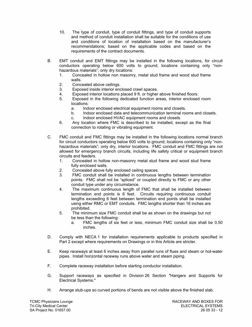
TCMC Physicians Lounge RACEWAY AND BOXES FORTri-City Medical Center ELECTRICAL SYSTEMSSA Project No. 01657.00 26 05 33 - 12
10. The type of conduit, type of conduit fittings, and type of conduit supports and method of conduit installation shall be suitable for the conditions of use and conditions of location of installation based on the manufacturer’s recommendations; based on the applicable codes and based on the requirements of the contract documents.
B. EMT conduit and EMT fittings may be installed in the following locations, for circuit conductors operating below 600 volts to ground; locations containing only “non-hazardous materials”; only dry locations:1. Concealed in hollow non masonry, metal stud frame and wood stud frame
walls.2. Concealed above ceilings.3. Exposed inside interior enclosed crawl spaces.4. Exposed interior locations placed 9 ft. or higher above finished floors.5. Exposed in the following dedicated function areas, interior enclosed room
locations:a. Indoor enclosed electrical equipment rooms and closets.b. Indoor enclosed data and telecommunication terminal rooms and closets.c. Indoor enclosed HVAC equipment rooms and closets.
6. Any location where FMC is described to be installed, except as the final connection to rotating or vibrating equipment.
C. FMC conduit and FMC fittings may be installed in the following locations normal branch for circuit conductors operating below 600 volts to ground; locations containing only “non-hazardous materials”; only dry, interior locations. FMC conduit and FMC fittings are not allowed for emergency branch circuits, including life safety critical or equipment branch circuits and feeders.1. Concealed in hollow non-masonry metal stud frame and wood stud frame
fully enclosed walls.2. Concealed above fully enclosed ceiling spaces.3. FMC conduit shall be installed in continuous lengths between termination
points. FMC shall not be “spliced” or coupled directly to FMC or any other conduit type under any circumstance.
4. The maximum continuous length of FMC that shall be installed between termination end points is 6 feet. Circuits requiring continuous conduit lengths exceeding 6 feet between termination end points shall be installed using either RMC or EMT conduits. FMC lengths shorter than 16 inches are prohibited.
5. The minimum size FMC conduit shall be as shown on the drawings but not be less than the following:a. FMC lengths of six feet or less, minimum FMC conduit size shall be 0.50
inches.
D. Comply with NECA 1 for installation requirements applicable to products specified in Part 2 except where requirements on Drawings or in this Article are stricter.
E. Keep raceways at least 6 inches away from parallel runs of flues and steam or hot-water pipes. Install horizontal raceway runs above water and steam piping.
F. Complete raceway installation before starting conductor installation.
G. Support raceways as specified in Division 26 Section "Hangers and Supports for Electrical Systems."
H. Arrange stub-ups so curved portions of bends are not visible above the finished slab.

TCMC Physicians Lounge RACEWAY AND BOXES FORTri-City Medical Center ELECTRICAL SYSTEMSSA Project No. 01657.00 26 05 33 - 13
I. Install no more than the equivalent of three 90-degree bends in any conduit run except for communications conduits, for which fewer bends are allowed.
J. Conceal conduit and EMT within finished walls, ceilings, and floors, unless otherwise indicated.
K. Threaded Conduit Joints, Exposed to Wet, Damp, Corrosive, or Outdoor Conditions: Apply listed compound to threads of raceway and fittings before making up joints. Follow compound manufacturer's written instructions.
L. Raceway Terminations at Locations Subject to Moisture or Vibration: Use insulating bushings to protect conductors, including conductors smaller than No. 4 AWG.
M. Install pull wires in empty raceways. Use polypropylene or monofilament plastic line with not less than 200-lb tensile strength. Leave at least 12 inches of slack at each end of pull wire.
N. Raceways for Optical Fiber and Communications Cable: Install raceways, metallic and nonmetallic, rigid and flexible, as follows:1. 3/4-Inch Trade Size and Smaller: Install raceways in maximum lengths of
50 feet.2. 1-Inch Trade Size and Larger: Install raceways in maximum lengths of 75
feet.3. Install with a maximum of two 90-degree bends or equivalent for each
length of raceway unless Drawings show stricter requirements. Separate lengths with pull or junction boxes or terminations at distribution frames or cabinets where necessary to comply with these requirements.
O. Install raceway sealing fittings at suitable, approved, and accessible locations and fill them with listed sealing compound. For concealed raceways, install each fitting in a flush steel box with a blank cover plate having a finish similar to that of adjacent plates or surfaces. Install raceway sealing fittings at the following points:1. Where conduits pass from warm to cold locations, such as boundaries of
refrigerated spaces.2. Where otherwise required by NFPA 70.
P. Flexible Conduit Connections: Use maximum of 72 inches of flexible conduit for recessed and semirecessed lighting fixtures, equipment subject to vibration, noise transmission, or movement; and for transformers and motors.1. Use LFMC in damp or wet locations subject to severe physical damage.
Q. Recessed Boxes in Masonry Walls: Saw-cut opening for box in center of cell of masonry block, and install box flush with surface of wall.
R. Set metal floor boxes level and flush with finished floor surface.
S. Set nonmetallic floor boxes level. Trim after installation to fit flush with finished floor surface.
3.03 SLEEVE INSTALLATION FOR ELECTRICAL PENETRATIONS
A. Coordinate sleeve selection and application with selection and application of firestopping specified in Division 07 Section "Penetration Firestopping."

TCMC Physicians Lounge RACEWAY AND BOXES FORTri-City Medical Center ELECTRICAL SYSTEMSSA Project No. 01657.00 26 05 33 - 14
B. Provide sleeves for raceways and conduit passing through the following construction elements:1. Concrete and masonry foundations, floors, walls and slabs.2. Lath and plaster walls and ceilings.3. Building structures (ie., foundations, walls, floors, ceilings, and roofs) with a
fire rating exceeding 20 minutes.
C. Concrete Slabs and Walls: Install sleeves for penetrations unless core-drilled holes or formed openings are used. Install sleeves during erection of slabs and walls.
D. Use pipe sleeves unless penetration arrangement requires rectangular sleeved opening.
E. Rectangular Sleeve Minimum Metal Thickness:1. For sleeve cross-section rectangle perimeter less than 50 inches and no
side greater than 16 inches, thickness shall be 0.052 inch.2. For sleeve cross-section rectangle perimeter equal to, or greater than, 50
inches and 1 or more sides equal to, or greater than, 16 inches, thickness shall be 0.138 inch.
F. Fire-Rated Assemblies: Install sleeves for penetrations of fire-rated floor and wall assemblies unless openings compatible with firestop system used are fabricated during construction of floor or wall.
G. Cut sleeves to length for mounting flush with both surfaces of walls.
H. Extend sleeves installed in floors 2 inches above finished floor level, except under floor standing electrical equipment. Sleeves shall be flush with wall ceiling foundations and partitions exposed to public view and extend approximately 0.5 inch past penetration in fire rated construction. Sleeves shall be installed at exact penetration locations and angles to accommodate raceway and conduit routings.
I. Joists, girders, beams, columns or reinforcing steel shall not be cut or weakened. Where construction necessitates the routing of conduit or raceways through structural members, framing or footings, written permission to make such installation shall first be obtained from the OWNER’S REPRESENTATIVE. Such permission will not be granted, however, if any other method of installation is possible.
J. The layout and design of raceways and conduits located in or routed through masonry or reinforced beams or the OWNER’S REPRESENTATIVE shall review walls before any work is performed. All sleeving shall be accomplished according to the instructions of the OWNER’S REPRESENTATIVE and shall be accepted before any concrete is poured.
K. Sleeves, raceways and conduit shall be located to clear steel reinforcing bars in beams. Reinforcing bars in walls shall be offset to clear piping and sleeves.
L. Provide a continuous clearance between the inside of a sleeve and exterior of conduits and raceways passing through the sleeve not less than the following:1. 0.5 inch clearance except as required otherwise.2. 1.0 inch clearance through outside walls below grade.3. 3.0 inch clearance through seismic joints.
M. Size pipe sleeves to provide 1/4-inch annular clear space between sleeve and raceway unless sleeve seal is to be installed or unless seismic criteria require different clearance.

TCMC Physicians Lounge RACEWAY AND BOXES FORTri-City Medical Center ELECTRICAL SYSTEMSSA Project No. 01657.00 26 05 33 - 15
N. Seal space outside of sleeves with grout for penetrations of concrete and masonry and with approved joint compound for gypsum board assemblies.
O. Interior Penetrations of Non-Fire-Rated Walls and Floors: Seal annular space between sleeve and raceway, using joint sealant appropriate for size, depth, and location of joint. Refer to Division 07 Section "Joint Sealants" for materials and installation.
P. Fire-Rated-Assembly Penetrations: Maintain indicated fire rating of walls, partitions, ceilings, and floors at raceway penetrations. Install sleeves and seal with firestop materials. Comply with Division 07 Section "Penetration Firestopping."
Q. Roof-Penetration Sleeves: Seal penetration of individual raceways with flexible, boot-type flashing units applied in coordination with roofing work.
R. Aboveground, Exterior-Wall Penetrations: Seal penetrations using sleeves and mechanical sleeve seals. Select sleeve size to allow for 1-inch annular clear space between pipe and sleeve for installing mechanical sleeve seals.
S. Underground, Exterior-Wall Penetrations: Install cast-iron "wall pipes" for sleeves. Size sleeves to allow for 1-inch annular clear space between raceway and sleeve for installing mechanical sleeve seals.
T. Sleeve Material:1. In floor construction: Schedule 40 black steel pipe, with upper surface to be
sealed watertight.2. In concrete or masonry walls roofs or ceilings: Schedule 40 black steel
pipe. When installed in roofs or outside walls, seal outer surface watertight.3. In fire rated construction; lath and plaster construction: 24 gauge
galvanized iron or steel.4. Sleeves through waterproof membranes: Cast iron or Schedule 40 steel
with flashing clamp device and corrosion resistant clamping bolts. Caulk space between pipe and sleeve and surfaces between sleeve and conduits sealed watertight.
3.04 SLEEVE-SEAL INSTALLATION
A. Install to seal underground, exterior wall penetrations.
B. Use type and number of sealing elements recommended by manufacturer for raceway material and size. Position raceway in center of sleeve. Assemble mechanical sleeve seals and install in annular space between raceway and sleeve. Tighten bolts against pressure plates that cause sealing elements to expand and make watertight seal.
3.05 FIRESTOPPING
A. Apply firestopping to electrical penetrations of fire-rated floor and wall assemblies to restore original fire-resistance rating of assembly. Firestopping materials and installation requirements are specified in Division 07 Section "Penetration Firestopping."
3.06 PROTECTION
A. Provide final protection and maintain conditions that ensure coatings, finishes, and cabinets are without damage or deterioration at time of Substantial Completion.1. Repair damage to galvanized finishes with zinc-rich paint recommended by
manufacturer.

TCMC Physicians Lounge RACEWAY AND BOXES FORTri-City Medical Center ELECTRICAL SYSTEMSSA Project No. 01657.00 26 05 33 - 16
2. Repair damage to PVC or paint finishes with matching touchup coating recommended by manufacturer.
3.07 INSTALLATION OF OUTLET AND JUNCTION BOXES
A. Accurately place boxes and securely fasten to structural members. Where outlets are shown at same location but at different mounting heights, install outlets in one vertical line. Where outlets are shown at same location and mounting height, mount outlets as close together in a horizontal row as possible. Where the outlet boxes for switches and receptacles are shown at the same location and mounting height, mount in common outlet box with barriers between devices. Provide single piece multigang cover plate for close mounted outlet boxes. Where switches are shown on wall adjacent to hinge side of doors, box shall be installed to clear door when door is fully opened.
B. Mount boxes at heights indicated on Drawings. If mounting heights of boxes are not individually indicated, give priority to ADA requirements. Install boxes with height measured to bottom of box unless otherwise indicated.
C. Flush mounted boxes shall be attached to two studs or structural member by means of metal supports.
D. Boxes above accessible ceilings shall be attached to structural members. Where boxes are suspended, they shall be supported independently of conduit system by means of hanger rods and/or preformed steel channels. Boxes shall be supported independently of all piping, ductwork, equipment, ceiling hanger wires and suspended ceiling grid system.
E. Recessed Boxes in Masonry Walls: Saw-cut opening for box in center of cell of masonry block, and install box flush with surface of wall. Prepare block surfaces to provide a flat surface for a raintight connection between box and cover plate or supported equipment and box.
F. Surface mounted outlets shall be attached to concrete or masonry walls by means of expansion shields.
G. Horizontally separate boxes mounted on opposite sides of walls so they are not in the same vertical channel.
H. Locate boxes so that cover or plate will not span different building finishes.
I. Support boxes of three gangs or more from more than one side by spanning two framing members or mounting on brackets specifically designed for the purpose.
J. Fasten junction and pull boxes to or support from building structure. Do not support boxes by conduits.
K. Set metal floor boxes level and flush with finished floor surface and within adjustable limits of floor ring. Where outlets are shown at same location or adjacent location, use multigang boxes.
L. Outlet box horizontal and vertical separation unless noted otherwise. Outlet boxes and device outlet rings installed flush in walls shall be horizontally and vertically separated by not less than 24 inches (edge of box to edge of box) from device outlet boxes and rings in common wall surfaces located on the opposite (back) side of the same wall.

TCMC Physicians Lounge RACEWAY AND BOXES FORTri-City Medical Center ELECTRICAL SYSTEMSSA Project No. 01657.00 26 05 33 - 17
1. Where the separation cannot be maintained, provide a solid backing behind the outlet box. The backing shall extend the width of the wall cavity (i.e. between "studs" or masonry cells) behind the box and 12 inches above and below the outlet box centerline. The backing shall consist of 5/8-inch thick gypsum board anchored in place for "stud" wall construction and solid "mortar" to completely fill the outlet box "cell" in masonry construction.
2. In fire rated walls where the separation cannot be maintained, provide fire rated "box-wrap" around each outlet box inside the wall, to maintain the fire rating of wall with the installed outlet boxes.
M. Set nonmetallic floor boxes level. Trim after installation to fit flush with finished floor surface.
3.08 WIREWAY INSALLATION
A. Wireway hangers shall provide clamp type, hanger rod type, direct bolted bracket type from ceiling or walls as indicated on the drawings and required for field installation locations. Supports shall be installed a minimum of 5 ft. on center.
3.09 GROUNDING (ADDITIONAL REQUIREMENTS)
A. Grounding shall be executed in accordance with all applicable codes and regulations, both of the State of California and local authorities having jurisdiction.
B. The neutral of each transformer shall be grounded by individual separate ground conductors in individual conduits as follows:
1. Conductor and conduit shall be grounded to building main ground bus. 2. Conductor and conduit shall be grounded to nearest available effectively
grounded building structural steel member or grounded metal cold water pipe.
C. The transformer neutral ground conductors for secondary side of the transformers shall be copper and shall be sized according to the following table: 1. Secondary Total Equivalent Neutral Ground2. Size Copper Wire Size Copper3. #2 or smaller #6-1" conduit4. 1 or 1/0 #4-1" conduit5. 2/0 or 3/0 #2-1 1/4" conduit6. 4/0 thru 350 MCM #1-1 1/4" conduit7. Over 350 MCM thru 600 MCM 2/0-1 1/2" conduit8. Over 600 MCM thru 1100 MCM 3/0-1 1/2" conduit9. Over 1100 MCM 4/0-2" conduit
D. Each pull box or any other enclosure in which several ground wires are terminated shall be equipped with a ground bus secured to the interior of the enclosure. The bus shall have a separate lug for each ground conductor. No more than one conductor shall be installed per lug.
E. The maximum resistance to ground shall not exceed 5 ohms.
END OF SECTION


TCMC Physicians LoungeTri-City Medical Center IDENTIFICATION FOR ELECTRICAL SYSTEMSSA Project No. 01657.00 26 05 53 - 1
SECTION 26 05 53
IDENTIFICATION FOR ELECTRICAL SYSTEMS
PART 1 GENERAL
1.01 RELATED DOCUMENTS
A. Drawings and general provisions of the Contract, including General and Supplementary Conditions and Division 01 Specification Sections, apply to this Section.
1.02 SUMMARY
A. Section Includes:1. Identification for raceways.2. Identification of power and control cables.3. Identification for conductors.4. Miscellaneous identification products.
1.03 SUBMITTALS
A. Product Data: For each electrical identification product indicated.
1.04 QUALITY ASSURANCE
A. Comply with ANSI A13.1.
B. Comply with NFPA 70.
C. Comply with 29 CFR 1910.144 and 29 CFR 1910.145.
D. Comply with ANSI Z535.4 for safety signs and labels.
E. Adhesive-attached labeling materials, including label stocks, laminating adhesives, and inks used by label printers, shall comply with UL 969.
1.05 COORDINATION
A. Coordinate identification names, abbreviations, colors, and other features with requirements in other Sections requiring identification applications, Drawings, Shop Drawings, manufacturer's wiring diagrams, and the Operation and Maintenance Manual; and with those required by codes, standards, and 29 CFR 1910.145. Use consistent designations throughout Project.
B. Coordinate installation of identifying devices with completion of covering and painting of surfaces where devices are to be applied.
C. Coordinate installation of identifying devices with location of access panels and doors.
D. Install identifying devices before installing acoustical ceilings and similar concealment.

TCMC Physicians LoungeTri-City Medical Center IDENTIFICATION FOR ELECTRICAL SYSTEMSSA Project No. 01657.00 26 05 53 - 2
PART 2 PRODUCTS
2.01 POWER RACEWAY IDENTIFICATION MATERIALS
A. Comply with ANSI A13.1 for minimum size of letters for legend and for minimum length of color field for each raceway size.
B. Colors for Raceways Carrying Circuits at 600 V or Less: 1. Black letters on an orange field.2. Legend: Indicate voltage and system or service type.
C. Self-Adhesive Vinyl Labels for Raceways Carrying Circuits at 600 V or Less: Preprinted, flexible label laminated with a clear, weather- and chemical-resistant coating and matching wraparound adhesive tape for securing ends of legend label.
D. Metal Tags: Brass or aluminum, 2 by 2 by 0.05 inch, with stamped legend, punched for use with self-locking cable tie fastener.
2.02 POWER AND CONTROL CABLE IDENTIFICATION MATERIALS
A. Comply with ANSI A13.1 for minimum size of letters for legend and for minimum length of color field for each raceway and cable size.
B. Self-Adhesive Vinyl Labels: Preprinted, flexible label laminated with a clear, weather- and chemical-resistant coating and matching wraparound adhesive tape for securing ends of legend label.
C. Metal Tags: Brass or aluminum, 2 by 2 by 0.05 inch, with stamped legend, punched for use with self-locking cable tie fastener.
D. Snap-Around Labels: Slit, pretensioned, flexible, preprinted, color-coded acrylic sleeve, with diameter sized to suit diameter of raceway or cable it identifies and to stay in place by gripping action.
2.03 CONDUCTOR IDENTIFICATION MATERIALS
A. Color-Coding Conductor Tape: Colored, self-adhesive vinyl tape not less than 3 mils thick by 1 to 2 inches wide.
2.04 CABLE TIES
A. General-Purpose Cable Ties: Fungus inert, self extinguishing, one piece, self locking, Type 6/6 nylon.1. Minimum Width: 3/16 inch.2. Tensile Strength at 73 deg F, According to ASTM D 638: 12,000 psi.3. Temperature Range: Minus 40 to plus 185 deg F.4. Color: Black except where used for color-coding.
B. UV-Stabilized Cable Ties: Fungus inert, designed for continuous exposure to exterior sunlight, self extinguishing, one piece, self locking, Type 6/6 nylon.1. Minimum Width: 3/16 inch.2. Tensile Strength at 73 deg F, According to ASTM D 638: 12,000 psi.3. Temperature Range: Minus 40 to plus 185 deg F.4. Color: Black.

TCMC Physicians LoungeTri-City Medical Center IDENTIFICATION FOR ELECTRICAL SYSTEMSSA Project No. 01657.00 26 05 53 - 3
C. Plenum-Rated Cable Ties: Self extinguishing, UV stabilized, one piece, self locking.1. Minimum Width: 3/16 inch.2. Tensile Strength at 73 deg F, According to ASTM D 638: 7000 psi.3. UL 94 Flame Rating: 94V-0.4. Temperature Range: Minus 50 to plus 284 deg F.5. Color: Black.
2.05 MISCELLANEOUS IDENTIFICATION PRODUCTS
A. Paint: Comply with requirements in Division 09 painting Sections for paint materials and application requirements. Select paint system applicable for surface material and location (exterior or interior).
B. Fasteners for Labels and Signs: Self-tapping, stainless-steel screws or stainless-steel machine screws with nuts and flat and lock washers.
PART 3 EXECUTION
3.01 INSTALLATION
A. Verify identity of each item before installing identification products.
B. Location: Install identification materials and devices at locations for most convenient viewing without interference with operation and maintenance of equipment.
C. Apply identification devices to surfaces that require finish after completing finish work.
D. Self-Adhesive Identification Products: Clean surfaces before application, using materials and methods recommended by manufacturer of identification device.
E. Cable Ties: For attaching tags. Use general-purpose type, except as listed below:1. Outdoors: UV-stabilized nylon.2. In Spaces Handling Environmental Air: Plenum rated.
END OF SECTION


TCMC Physicians LoungeTri-City Medical Center WIRING DEVICESSA Project No. 01657.00 26 27 26 - 1
SECTION 26 27 26
WIRING DEVICES
PART 1 GENERAL
1.01 RELATED DOCUMENTS
A. Drawings and general provisions of the Contract, including General and Supplementary Conditions and Division 01 Specification Sections, apply to this Section.
1.02 SUMMARY
A. This Section includes the following:1. Receptacles, receptacles with integral GFCI, and associated device plates.
1.03 DEFINITIONS
A. GFCI: Ground-fault circuit interrupter.
B. Pigtail: Short lead used to connect a device to a branch-circuit conductor.
1.04 SCOPE
A. Work Included: All labor, materials, appliances, tools, equipment, facilities, transportation and services necessary for and incidental to performing all operations in connection with furnishing, delivery and installation of the work of this Section, complete as shown on the drawings and/or specified herein. Work includes, but is not necessarily limited to the following:1. Examine all other sections for work related to those other sections and required to
be included as work under this section.2. General provisions and requirements for electrical work.
1.05 SUBMITTALS
A. Product Data: For each type of product indicated.
B. Field quality-control test reports.
C. Operation and Maintenance Data: For wiring devices to include in all manufacturers' packing label warnings and instruction manuals that include labeling conditions.
1.06 QUALITY ASSURANCE
A. Source Limitations: Obtain each type of wiring device and associated wall plate through one source from a single manufacturer. Insofar as they are available, obtain all wiring devices and associated wall plates from a single manufacturer and one source.
B. Electrical Components, Devices, and Accessories: Listed and labeled as defined in NFPA 70, Article 100, by a testing agency acceptable to authorities having jurisdiction, and marked for intended use.
C. Comply with NFPA 70.

TCMC Physicians LoungeTri-City Medical Center WIRING DEVICESSA Project No. 01657.00 26 27 26 - 2
1.07 COORDINATION
A. Receptacles for Owner-Furnished Equipment: Match plug configurations.1. Cord and Plug Sets: Match equipment requirements.
PART 2 PRODUCTS
2.01 MANUFACTURERS
A. Manufacturers' Names: Shortened versions (shown in parentheses) of the following manufacturers' names are used in other Part 2 articles:1. Cooper Wiring Devices; a division of Cooper Industries, Inc. (Cooper).2. Hubbell Incorporated; Wiring Device-Kellems (Hubbell).3. Leviton Mfg. Company Inc. (Leviton).4. Pass & Seymour/Legrand; Wiring Devices & Accessories (Pass & Seymour).
2.02 STRAIGHT BLADE RECEPTACLES (SHALL BE UL LISTED HOSPITAL GRADE)
A. All receptacles in flush type outlet boxes shall be installed with bonding jumper to connect to box to the receptacles ground terminal. Grounding through the receptacle mounting straps is not acceptable. The bonding jumper shall be sized in accordance with the branch circuit protective device as tabulated herein under "Grounding". Bonding jumper shall be attached at each outlet to the back of the box using drilled and tapped holes and washer head screws 6-32 or larger (except isolated ground receptacles). For receptacles in surface mounted outlet boxes direct metal-to-metal contact between receptacle mounting strap (if it is connected to the grounding contacts) and outlet box may be used. Receptacles connected to normal circuits shall be ivory, white or gray as selected by ARCHITECT. Receptacles connected to emergency (ESSENTIAL) power circuits shall be red.
B. Hospital-Grade, Duplex Convenience Receptacles, 125 V, 20 A: Comply with NEMA WD 1, NEMA WD 6 configuration 5-20R, and UL 498 Supplement SD.1. Products: Subject to compliance with requirements, provide one of the following:
a. Cooper; 8300 (duplex).b. Hubbell; HBL8310 (single), HBL8300H (duplex).c. Leviton; 8310 (single), 8300 (duplex).d. Pass & Seymour; 9301-HG (single), 9300-HG (duplex).
C. Isolated-Ground, Duplex Convenience Receptacles, 125 V, 20 A: Comply with NEMA WD 1, NEMA WD 6 configuration 5-20R, and UL 498.1. Products: Subject to compliance with requirements, provide one of the following:
a. Hubbell; CR 5253IG.b. Leviton; 5362-IG.c. Pass & Seymour; IG6300.
2. Description: Straight blade; equipment grounding contacts shall be connected only to the green grounding screw terminal of the device and with inherent electrical isolation from mounting strap. Isolation shall be integral to receptacle construction and not dependent on removable parts.
D. Tamper-Resistant Convenience Receptacles, 125 V, 20 A: Comply with NEMA WD 1, NEMA WD 6 configuration 5-20R, and UL 498.1. Products: Subject to compliance with requirements, provide one of the following:
a. Cooper; TR8300.b. Hubbell; HBL8300SG.

TCMC Physicians LoungeTri-City Medical Center WIRING DEVICESSA Project No. 01657.00 26 27 26 - 3
c. Leviton; 8300-SGG.d. Pass & Seymour; 63H.
2. Description: Labeled to comply with NFPA 70, "Health Care Facilities" Article, "Pediatric Locations" Section.
2.03 GFCI RECEPTACLES (SHALL BE UL LISTED HOSPITAL GRADE)
A. General Description: Straight blade, feed-through type. Comply with NEMA WD 1, NEMA WD 6, UL 498, and UL 943, Class A, and include indicator light that is lighted when device is tripped.
B. Hospital-Grade, Duplex GFCI Convenience Receptacles, 125 V, 20 A: Comply with UL 498 Supplement SD.1. Products: Subject to compliance with requirements, provide one of the following:
a. Cooper; HGF20.b. Hubbell; HGF8300.c. Leviton; 6898-HG.d. Pass & Seymour; 2091-SHG.
2.04 CORD AND PLUG SETS
A. Description: Match voltage and current ratings and number of conductors to requirements of equipment being connected.1. Cord: Rubber-insulated, stranded-copper conductors, with Type SOW-A jacket;
with green-insulated grounding conductor and equipment-rating ampacity plus a minimum of 30 percent.
2. Plug: Nylon body and integral cable-clamping jaws. Match cord and receptacle type for connection.
2.05 WALL PLATES
A. Provide plates for every normal power switch, normal power receptacle, telephone, computer, television and other device outlets. All plates shall be Pass & Seymour Type “SRP” thermoset plastic color shall be ivory, white or gray as selected by ARCHITECT. Refer to Section 26 “Identification for Electrical Systems” and Section 26 “Medical Facilities” for engraving requirements.
B. Provide plates for every emergency (ESSENTIAL) power switch, emergency (ESSENTIAL) power receptacle, and other emergency (ESSENTIAL) power device outlets. All plates shall be Pass & Seymour Type “SRP” thermoset plastic color shall be red for emergency (ESSENTIAL) power device outlets. Refer to Section 26 “Identification for Electrical Systems” and Section 26 “Medical Facilities” for engraving requirements.
C. Single and combination types to match corresponding wiring devices.1. Plate-Securing Screws: Metal with head color to match plate finish.2. Material for Finished Spaces: Smooth, high-impact thermoplastic.3. Material for Unfinished Spaces: Smooth, high-impact thermoplastic.4. Material for Damp Locations: with spring-loaded lift cover, and listed and labeled
for use in "wet locations."5. Color: Refer to Architectural plans and specifications.
D. Wet-Location, Weatherproof Cover Plates: NEMA 250, complying with type 3R weather-resistant thermoplastic with lockable cover.

TCMC Physicians LoungeTri-City Medical Center WIRING DEVICESSA Project No. 01657.00 26 27 26 - 4
2.06 FINISHES
A. Color: Wiring device catalog numbers in Section Text do not designate device color.1. Wiring Devices Connected to Normal Power System: ivory, white or gray as
selected by Architect, unless otherwise indicated or required by NFPA 70 or device listing.
2. Wiring Devices Connected to Emergency (ESSENTIAL) Power System: Red.3. TVSS Devices: Blue.4. Isolated-Ground Receptacles: Orange.
2.07 IDENTIFICATION (ADDITIONAL REQUIREMENTS)
A. The front face device cover plates for switches and outlets shall be engraved with the circuit number and connection source equipment name with 1/4” letters, (i.e. "PNL-A #1"; "PNL-AC #42"; etc.) Additionally device cover plates shall also be engraved 1/8” letters with the circuit ampacity and voltage for circuit exceeding 20 ampere or 120 volts. (i.e. PNL-A #6, 8 - 20 AMP 208V 1 Phase; PNL-2B #10 - 30 AMP 120V 1 Phase; etc.) Lettering for normal circuits shall be black lettering for emergency (essential) circuits shall be black.
PART 3 EXECUTION
3.01 INSTALLATION
A. Comply with NECA 1, including the mounting heights listed in that standard, unless otherwise noted.
B. Coordination with Other Trades:1. Take steps to insure that devices and their boxes are protected. Do not place wall
finish materials over device boxes and do not cut holes for boxes with routers that are guided by riding against outside of the boxes.
2. Keep outlet boxes free of plaster, drywall joint compound, mortar, cement, concrete, dust, paint, and other material that may contaminate the raceway system, conductors, and cables.
3. Install device boxes in brick or block walls so that the cover plate does not cross a joint unless the joint is troweled flush with the face of the wall.
4. Install wiring devices after all wall preparation, including painting, is complete.
C. Conductors:1. Do not strip insulation from conductors until just before they are spliced or
terminated on devices.2. Strip insulation evenly around the conductor using tools designed for the purpose.
Avoid scoring or nicking of solid wire or cutting strands from stranded wire.3. The length of free conductors at outlets for devices shall meet provisions of
NFPA 70, Article 300, without pigtails.4. Existing Conductors:
a. Cut back and pigtail, or replace all damaged conductors.b. Straighten conductors that remain and remove corrosion and foreign matter.c. Pigtailing existing conductors is permitted provided the outlet box is large
enough.
D. Device Installation:

TCMC Physicians LoungeTri-City Medical Center WIRING DEVICESSA Project No. 01657.00 26 27 26 - 5
1. Replace all devices that have been in temporary use during construction or that show signs that they were installed before building finishing operations were complete.
2. Keep each wiring device in its package or otherwise protected until it is time to connect conductors.
3. Do not remove surface protection, such as plastic film and smudge covers, until the last possible moment.
4. Connect devices to branch circuits using pigtails that are not less than 6 inches in length.
5. When there is a choice, use side wiring with binding-head screw terminals. Wrap solid conductor tightly clockwise, 2/3 to 3/4 of the way around terminal screw.
6. Use a torque screwdriver when a torque is recommended or required by the manufacturer.
7. When conductors larger than No. 12 AWG are installed on 15- or 20-A circuits, splice No. 12 AWG pigtails for device connections.
8. Tighten unused terminal screws on the device.9. When mounting into metal boxes, remove the fiber or plastic washers used to hold
device mounting screws in yokes, allowing metal-to-metal contact.
E. Receptacle Orientation:1. Install ground pin of vertically mounted receptacles up, and on horizontally
mounted receptacles to the right.2. Install hospital-grade receptacles in patient-care areas with the ground pin or
neutral blade at the top.
F. Device Plates: Do not use oversized or extra-deep plates. Repair wall finishes and remount outlet boxes when standard device plates do not fit flush or do not cover rough wall opening.
G. Dimmers:1. Install dimmers within terms of their listing.2. Verify that dimmers used for fan speed control are listed for that application.3. Install unshared neutral conductors on line and load side of dimmers according to
manufacturers' device listing conditions in the written instructions.4. Do not break off dimmer cooling fans.
H. Arrangement of Devices: Unless otherwise indicated, mount flush, with long dimension vertical and with grounding terminal of receptacles on top. Group adjacent switches under single, multigang wall plates.
I. Adjust locations of floor service outlets and service poles to suit arrangement of partitions and furnishings.
J. Occupancy Sensor Light Switches1. Install dimmers within terms of their listing. Installation and location of occupancy
sensors shall be in accordance with manufacturers recommendations.2. Adjust sensitivity control as required for proper operation and to limit coverage to
room controlled. Adjust sensitivity so that persons passing by an open door to the room controlled will not activate the lights and for minimal motion within the room by the occupant will maintain the lights on.
3. Adjust time delay off for 15 minutes.
3.02 IDENTIFICATION
A. Comply with Division 26 Section "Medical Facilities."

TCMC Physicians LoungeTri-City Medical Center WIRING DEVICESSA Project No. 01657.00 26 27 26 - 6
1. Receptacles: Identify panelboard and circuit number from which served. Use hot, stamped or engraved machine printing with black-filled lettering on face of plate, and durable wire markers or tags inside outlet boxes.
3.03 FIELD QUALITY CONTROL
A. Perform tests and inspections and prepare test reports.1. In healthcare facilities, prepare reports that comply with recommendations in
NFPA 99.2. Test Instruments: Use instruments that comply with UL 1436.3. Test Instrument for Convenience Receptacles: Digital wiring analyzer with digital
readout or illuminated LED indicators of measurement.
B. Tests for Convenience Receptacles:1. Line Voltage: Acceptable range is 105 to 132 V.2. Percent Voltage Drop under 15-A Load: A value of 6 percent or higher is not
acceptable.3. Ground Impedance: Values of up to 2 ohms are acceptable.4. GFCI Trip: Test for tripping values specified in UL 1436 and UL 943.5. Using the test plug, verify that the device and its outlet box are securely mounted.6. The tests shall be diagnostic, indicating damaged conductors, high resistance at
the circuit breaker, poor connections, inadequate fault current path, defective devices, or similar problems. Correct circuit conditions, remove malfunctioning units and replace with new ones, and retest as specified above.
C. Test straight blade convenience outlets in patient-care areas for the retention force of the grounding blade according to NFPA 99. Retention force shall be not less than 4 oz..
END OF SECTION

TCMC Physicians LoungeTri-City Medical Center MEDICAL FACILITIESSA Project No. 01657.00 26 57 00 - 1
SECTION 26 57 00
MEDICAL FACILITIES
PART 1 GENERAL
1.01 SCOPE
A. Work Included: All labor, materials, appliances, tools, equipment, facilities, transportation and services necessary for and incidental to performing all operations in connection with furnishing, deliver and installation of the work of this Section, complete as shown on the drawings and/or specified herein. Work includes, but is not necessarily limited to the following:1. Examine all other sections for work related to those other sections and required to be
included as work under this section.2. General provisions and requirements for electrical work.
1.02 SUBMITTALS (ADDITIONAL REQUIREMENTS)
A. Submit product data sheets for all outlet boxes, wiring devices, device plates.
PART 2 PRODUCTS
2.01 RECEPTACLES (ADDITIONAL REQUIREMENTS)
A. Receptacles shall be Underwriters Laboratories listed hospital grade.1. Duplex convenience receptacles shall be heavy duty grounding type 120 volt 15 ampere
with two current carrying contacts and one grounding contact which is internally connected to the frame. Outlets shall accommodate standard parallel blade cap and be side wired. Receptacles on normal circuits shall be ivory, white or gray as selected by Architect. Receptacles on emergency (essential) circuit shall be red.a. Hubbell #8200
2. Duplex 20 ampere convenience outlets same as 15 ampere except ampacity shall be used where duplex receptacles is supplied by separate 20-ampere circuit:a. Hubbell #8300
3. Ground fault convenience receptacles provide separate ground fault receptacle at each location indicated on drawings.
a. Hubbell #GF8300
B. Special outlets hospital grade capacities and types shall be as indicated on the drawings.
2.02 IDENTIFICATION (ADDITIONAL REQUIREMENTS)
A. The front face device cover plates for switches and outlets shall be engraved with the circuit number and connection source equipment name with 1/4” letters, (i.e. "PNL-A #1"; "PNL-AC #42"; etc.) Additionally device cover plates shall also be engraved 1/8” letters with the circuit ampacity and voltage for circuit exceeding 20 ampere or 120 volts. (i.e. PNL-A #6, 8 - 20 AMP 208V 1 Phase; PNL-2B #10 - 30 AMP 120V 1 Phase; etc.) Lettering for normal circuits shall be black lettering for emergency (essential) circuits shall be red.
PART 3 EXECUTION
NONE
END OF SECTION


APP
END
ICES