
TCDG Cover 2013 v9 - Amazon Web...
28
ThermalClad ® SELECTION GUIDE Thermal Solutions For LEDs and Surface Mount Power Applications
-
Upload
trinhduong -
Category
Documents
-
view
214 -
download
0
Transcript of TCDG Cover 2013 v9 - Amazon Web...

ThermalClad®
S E L E C T I O N G U I D E
Thermal Solutions
For LEDs and Surface Mount
Power Applications
TCDG_Cover_2013 v9.qxp 8/22/2013 11:38 AM Page 3

All statements, technical information and recommendations herein are based on tests we believe to be reliable, andTHE FOLLOWING IS MADE IN LIEU OF ALL WARRANTIES, EXPRESSED OR IMPLIED, INCLUDING THEIMPLIED WARRANTIES OF MARKETABILITY AND FITNESS FOR PURPOSE. Sellers' and manufacturers'only obligation shall be to replace such quantity of the product proved to be defective. Before using, user shall deter-mine the suitability of the product for its intended use, and the user assumes all risks and liability whatsoever in con-nection therewith. NEITHER SELLER NOR MANUFACTURER SHALL BE LIABLE EITHER IN TORT OR INCONTRACT FOR ANY LOSS OR DAMAGE, DIRECT, INCIDENTAL, OR CONSEQUENTIAL, INCLUDINGLOSS OF PROFITS OR REVENUE ARISING OUT OF THE USE OR THE INABILITY TO USE A PRODUCT.No statement, purchase order or recommendations by seller or purchaser not contained herein shall have any force oreffect unless in an agreement signed by the officers of the seller and manufacturer.
August 2013 Thermal Clad®: U.S. Patent 4,810,563 and others.
ISO 9001Quality
Cer
tifie
d S
yste
m
TCDG_Cover_2013 v9.qxp 8/22/2013 11:38 AM Page 4

1
Table of Contents
Thermal CladThermal Clad Overview . . . . . . . . . . . . . . . . . . . . . . . . . . . . . . . . . . . . . . . . . . . . . . .2-3Thermal Clad Applications . . . . . . . . . . . . . . . . . . . . . . . . . . . . . . . . . . . . . . . . . . . . . . . .4Thermal Clad Reliability . . . . . . . . . . . . . . . . . . . . . . . . . . . . . . . . . . . . . . . . . . . . . . . . . .5
DielectricsSelecting Dielectric Materials . . . . . . . . . . . . . . . . . . . . . . . . . . . . . . . . . . . . . . . . . . . .6-7Dielectric Performance Considerations . . . . . . . . . . . . . . . . . . . . . . . . . . . . . . . . . . . . .8Summary Of Key Dielectric Characteristics . . . . . . . . . . . . . . . . . . . . . . . . . . . . . . . . . .9Advanced Circuit Processing . . . . . . . . . . . . . . . . . . . . . . . . . . . . . . . . . . . . . . . . . .10-11
Design ConsiderationsBaseplate Design Considerations . . . . . . . . . . . . . . . . . . . . . . . . . . . . . . . . . . . . . .12-13Selecting A Circuit Layer . . . . . . . . . . . . . . . . . . . . . . . . . . . . . . . . . . . . . . . . . . . . .14-15Electrical Design Considerations . . . . . . . . . . . . . . . . . . . . . . . . . . . . . . . . . . . . . . .16-17Assembly Recommendations . . . . . . . . . . . . . . . . . . . . . . . . . . . . . . . . . . . . . . . . . .18-19
Other Bergquist Thermal Products . . . . . . . . . . . . . . . . . . . . . . . . . . . . . . .20-21
Appendix . . . . . . . . . . . . . . . . . . . . . . . . . . . . . . . . . . . . . . . . . . . . . . . . . . . . . . . . . . . . . .22
Thermal Clad Configurations . . . . . . . . . . . . . . . . . . . . . . . . . . . . . . . . . . . . . . . .23
TClad_DGguts_2013 v28.qxp 10/3/2013 10:28 AM Page 1

(66) Thru-hole FETs (15) High profile capacitors (9) High profile bus bars Total Weight 3.4 lbs (1543.6g)
(48) FETs (9) Low profile capacitors (5) Low profile bus bars Total Weight 0.82 lbs (370.6g)
Thermal Clad is a complete thermal management system, unliketraditional technology which uses heat sinks, clips and othermounting hardware. Thermal Clad enables low-cost productionby eliminating the need for costly manual assembly.
2
Key Benefits Of Thermal CladThe Bergquist Company is the world leader in the develop-ment and manufacture of thermally conductive interface mate-rials.Thermal Clad Insulated Metal Substrate (IMS®) was devel-oped by Bergquist as a thermal management solution fortoday’s higher watt-density surface mount applications whereheat issues are a major concern.
Thermal Clad substrates minimize thermal impedance andconduct heat more effectively and efficiently than standardprinted wiring boards (PWB's). These substrates are moremechanically robust than thick-film ceramics and direct bondcopper constructions that are often used in these applications.
Thermal Clad is a cost-effective solution which can eliminatecomponents, allow for simplified designs, smaller devices and anoverall less complicated production processes. Additional ben-efits of Thermal Clad include lower operating temperatures,longer component life and increased durability.
Bergquist Thermal Clad substrates are not limited to use withmetal base layers. In one example, power conversion applica-tions can enhance their performance by replacing FR-4 withThermal Clad dielectrics in multi-layer assemblies. In this appli-cation, the thickness of the copper circuit layer can be mini-mized by the high thermal performance of Thermal Clad. Foradditional information on this topic, refer to the “SpecialtyApplications” section on pages 10-11 of this guide.
Thermal Clad® Overview
Cooling with Thermal Clad caneliminate the need for heat sinks, deviceclips, cooling fans and other hardware.An automated assembly method will
reduce long term costs.
Traditionally, cooling an FR-4 board required use of a large heat sink, interfacematerial and various hardware (brackets,
screws or clamps); a configuration requiringlabor intensive manual assembly.
Conventional methodsmeasured junction temperature
5W=Tj 43ºC
Thermal Cladmeasured junction temperature
5W=Tj 35ºC
®
Thermal Clad Benefits• RoHS and Reach compliant and halogen-free• Lower component operating temperatures• Reduce printed circuit board size• Increase power density• Extend the life of dies• Reduce the number of interconnects• Improve product thermal and mechanical performance• Combine power and control• Improve product durability• Enable better use of surface mount technology• Reduce heat sinks and other mounting hardware, including
thermal interface material• Replace fragile ceramic substrates with greater
mechanical durability• Bergquist is your one-stop source from raw materials
to finished circuit boards
Original Power Board Assembly (Actual)
New Power Board Assembly (Actual)
TClad_DGguts_2013 v28.qxp 10/3/2013 10:28 AM Page 2

3
Improve Durability and PerformanceThermal Clad improves durability because designs can be keptsimple while components are kept cool. The low thermalimpedance of the Thermal Clad dielectric outperforms otherinsulators for power components, allowing for cooler operation.
Thermal Clad keeps assemblies cool by eliminating thermalinterfaces and using thermally efficient solder joints. Voltagebreakdown and thermal performance improve in potted assem-blies using SMD’s and bare die on Thermal Clad.
Thermal Clad can also reduce production costs by enablingautomated pick-and-place equipment for SMD’s.
Reduce Board Size and Replace HardwareThermal Clad greatly reduces board space while replacing othercomponents including heat sinks. It offers the opportunity toeliminate mica and grease or rubber insulators under powerdevices by using direct solder mount to Thermal Clad. By elimi-nating this hardware, heat transfer is improved.
Interconnects can be eliminated by using etched traces on theThermal Clad board. In fact, whole sections of PWB’s are ofteneliminated. It permits the use of surface mount power and passive devices to reduce real estate.With Thermal Clad, manydiscrete devices can be replaced at the board level.
Dielectric Layer
Base Layer
Bergquist’s manufacturing facility located in Prescott, Wisconsin features state-of-the-artprocess capabilities. Process manufacturing uses the latest in technology including environmental clean room control, surface finishing, coating and lamination.
The Anatomy Of A Thermal Clad BoardThermal Clad is a dielectric (ceramic-polymer blend) coated metalbase with a bonded copper circuit layer.This unique material offerssuperior heat transfer to help cool components while eliminatingthe problems associated with fragile ceramics. Different than others,Bergquist doesn’t use fiberglass, allowing for better thermal perfor-mance.
Thermal Clad is a three layer system comprised of the following:
t Circuit Layer: This is the printed circuit foil with a thicknessrange of .5oz. to 10oz. (17-350µm) in standard Thermal Clad.
t Dielectric Layer: This offers electrical isolation with mini-mum thermal resistance. Glass carriers degrade thermal perfor-mance which is why our dielectrics are glass-free. CML is theone exception because of its prepreg form, a glass carrier isneeded for handling purposes.The dielectric layer is the key ele-ment of Thermal Clad, and bonds the base metal and circuitmetal together. The dielectric has U.L. recognition, simplifyingagency acceptance of final assemblies.
t Base Layer: This is often aluminum, but other metals such ascopper may also be used. The most widely used base materialthickness is 0.062" (1.57mm) in aluminum, although many thickness-es are available. In some applications, the base layer of metal maynot be needed. See “Advanced Circuit Processing” on page 11.
Circuit Layer
TClad_DGguts_2013 v28.qxp 10/3/2013 10:28 AM Page 3

4
Power ConversionDue to the size constraints and watt-densityrequirements in DC-DC conversion, ThermalClad has become the favored choice.ThermalClad is available in a variety of thermal perfor-mances, is compatible with mechanical fasten-ers and is highly reliable. It can be used inalmost every form-factor and fabricated in awide variety of substrate metals, thicknessesand copper foil weights.
Motor DrivesCompact high-reliability motor drives built onThermal Clad have set the benchmark forwatt-density. Dielectric choices provide theelectrical isolation necessary to meet operat-ing parameters and safety agency test require-ments. With the ability to fabricate in a widevariety of form-factors, implementation intoeither compact or integrated motor drives isrealized. The availability of Thermal Clad HTmakes high temperature operation possible.
Heat-Rail And FormingThe use of Thermal Clad in heat-rail applica-tions has increased significantly and is current-ly used in automotive, audio, motor controland power conversion applications. ThermalClad offers many advantages including surfacemount assembly, attachment capabilities andexcellent thermal performance. The dielectriccan be selectively removed and the metal canbe formed with three-dimensional featuresmaking Thermal Clad a versatile substrate.
LEDsIn Power LED applications, light output andlong life are directly attributable to howwell the LED’s are managed thermally.Thermal Clad is an excellent solution fordesigners. T-Clad is a metal based material(often referred to as a MCPCB), and can beconfigured for special shapes, bends and thick-nesses thus allowing the designer toput LED light engines in virtually any applica-tion. Mounting Power LED’s on T-Clad assuresthe lowest possible operating temperaturesand maximum brightness, color and life.
Solid State Relays/SwitchesThe implementation of Solid State Relays inmany control applications calls for thermallyefficient, and mechanically robust substrates.Thermal Clad offers both. The material con-struction allows mounting configurations notreasonably possible with ceramic substrates.New dielectrics meet the high thermal per-formance expectations and can even out-per-form existing ceramic based designs.
Thermal Clad Applications
Want to maximize the lifecycle andcolor consistency of your LEDs?This LED-specific solutions guide addresses important factors and recommendationsfor selecting a thermal managementsolution ideal for your LED design.
TClad_DGguts_2013 v28.qxp 10/3/2013 10:28 AM Page 4

Dynamic Mechanical Analysis (DMA) – Measures the modulus of materials over a range of temperatures.
Chamber Ovens – Over 3000 cubic feet (85 cubic meters)of oven capacity is dedicated to long term thermal bias agetesting. The ovens take material to temperatures above Tg.At selected intervals, samples are removed and tested toverify material integrity.
Thermogravimetric Analyzer (TGA) – Measures the stabilityof our dielectrics at high temperatures, baking the materialsat prescribed temperatures and measuring weight loss.
TTyyppiiccaall QQuuaalliiffiiccaattiioonn PPrrooggrraammss
Insulation ImpedanceTemp/Hum/Bias
85C/85%RH/100V2000 hours
Permittivity/DissipationTemp/Hum/Bias
85°C/85%RH/100V2000 hours
Thermal ShockSand Bath
300°C/1 minute and200°C/72 hour post
Ten CycleSolder Shock
Breakdown VoltageDC and AC
Sequential Aging
Peel AdhesionPull Strength
Sequential Aging
Thermal Bias Aging125°C/100V/2000h
Thermal Bias Aging125°C/100V/2000h
ThermalConductivity
FlammabilityThermal Stress230°C/10 min.
Thermal Stress230°C/10 min.
Thermal Bias Aging175°C/100V/2000h
Thermal Bias Aging175°C/100V/2000h
Temp Cycling500 cycles/-40°C-150°C
350 hours
Temp Cycling500 cycles/-40°C-150°C
350 hours
Temp/Hum/Bias85°C/85%RH/100V
2000 hours
Temp/Hum/Bias85°C/85%RH/100V
2000 hours
Chemical SoakLoncoterge - 15 min.
Alcohol - 15 min.
Chemical SoakLoncoterge - 15 min.
Alcohol - 15 min.
Thermal Bias Aging125°C/480V/2000h
Thermal Bias Aging125°C/480V/2000h
Thermal Aging125°C/2000 hours
Thermal Aging125°C/2000 hours
ElectricalProperties
Other PropertiesEvaluated
PhysicalProperties
Thermal Clad Long Term ReliabilityNew materials undergo a rigorous 12 to 18 month qualification pro-gram prior to being released to the market.
In state-of-the-art laboratories and test facilities, Bergquist performsextensive testing on all their thermal materials for electrical integrity.Bergquist utilizes stringent development procedures.The lab facilities atBergquist are U.L. cer tified and manufacturing facilities are ISO9001:2008 certified.
Extensive qualification testing consists of mechanical property valida-tion, adhesion, temperature cycling, thermal and electrical stress. To validate long term reliability, electrical testing is performed at selectedintervals to 2000 hours where final evaluation is completed.
To ensure consistent product performance with manufactured materi-als, we couple the up-front qualification test with regular audits. Auditsinclude physical, electrical and thermal property tests.
5
Thermal Clad Reliability
d
TClad_DGguts_2013 v28.qxp 10/3/2013 10:29 AM Page 5

Selecting Dielectric MaterialsDielectric LayerThe technology of Thermal Clad resides in the dielectric layer. It is thekey element for optimizing performance in your application.The dielec-tric is a proprietary polymer/ceramic blend that gives Thermal Clad itsexcellent electrical isolation properties and low thermal impedance.
The polymer is chosen for its electrical isolation properties, ability to resist thermal aging and high bond strengths. The ceramic fillerenhances thermal conductivity and maintains high dielectric strength.The result is a layer of isolation which can maintain these propertieseven at 0.0015" (38µm) thickness. Contact a Bergquist SalesRepresentative for thinner dielectric information. We will help youselect the best dielectric to suit your needs for watt-density, electricalisolation and operating temperature environment.
Standardized Methods ForMeasuring Thermal ConductivityThere are several different test methods for determining a material’sthermal conductivity value. Results can be different depending on themethod chosen, so it is important to use similar test methods inmaterial comparisons. See chart at right.
Standard test methods include ASTM D5470 and ASTM E1461.ASTM D5470 is a steady state method and is referred to as theguarded hot plate.This method provides an analytically derived valueand does not use approximations. ASTM E1461 is a transient methodreferred to as Laser Flash Diffusivity. In E1461, thermal diffusivity is thetest output and thermal conductivity is calculated.
Non-Standard In-House Test MethodsThe adjacent chart shows how vastly different thermal conductivityvalues can be achieved by using “in-house” or non-standard testmethods. For example, when the same dielectric is chosen we canderive a completely different and much higher thermal conductivityvalue by testing a stack-up or laminate with base layer. We can modifythe test further by using different materials for the substrate to obtaineven higher results. Although thermal conductivity values are still rela-tive to one another so a comparison can be made, these test meth-ods do not give us an accurate depiction of true thermal perfor-mance in the application. Included in the chart is a modeled value forthermal conductivity, a respected model for predicting the effectivethermal conductivity of anisotropic particulate composites, but nothelpful for determining thermal performance in application. Weemphasize using standard test methods such as ASTM D5470 andASTM E1461, which are universally accepted and repeatable.
Note: The hot disk method is not a method we use for comparisonbecause typically this method measures the conductivity of the dielectricalone, which neglects thermal interfacial resistance between layers andcarrier holding the dielectric. These values must be understood in order tocalculate the actual thermal impedance or thermal performance data.See section regarding thermal impedance on page 7.
LLooww
eerrTT
hheerrmm
aall PP
eerrffoo
rrmmaann
ccee
HHiigghheerr
TThheerrmm
aall PPeerrffoorrmmaannccee
CCMMLLCircuitMaterialLaminate
MMPPMulti-
Purpose
HHTTHigh
Temperature
HHPPLLHigh Power
Lighting
MMeetthhooddDDeessccrriippttiioonn
1 - Bruggeman Model
2 - Tested with 0.062" (1.57mm) 5052 aluminum substrateand 2 oz. (70µm) copper foil
3 - Tested with 0.062"(1.57mm) 1100 copper substrate and 2 oz. (70µm) foil
6
Thermal ConductivityThermal conductivity is relevant to the application’s thermal performancewhen the thickness of the dielectric material, interfacial resistance and areaare taken into consideration. See “Thermal Impedance” section for moreinformation, as this data will be the most relevant to your application.
MMeetthhooddDDeessccrriippttiioonn
1 - ASTM D5470Guarded Hot Plate
2 - ASTM E1461Laser Flash Diffusivity
Non-Standard Thermal Conductivity Test Methods and Model (W/m-K)
PartNumber Model1
GuardedHot PlateLaminate2
GuardedHot PlateLaminate3
Laser FlashLaminate2
Laser FlashLaminate3
HHTT--0044550033 9.0 32.2 36.4 67.6 115
HHTT--0077000066 9.0 21.5 23.3 46.0 86.5
MMPP--0066550033 4.5 14.0 24.0 34.9 102
StandardizedTest Methods (W/m-K)
PartNumber
ASTMD54701
ASTME14612
HHPPLL--0033001155 3.0 3.3
HHTT--0044550033 2.2 2.0
HHTT--0077000066 2.2 2.0
MMPP--0066550033 1.3 1.2
HHRR TT3300..2200 1.0 1.1
HHRR TT3300..2200
TClad_DGguts_2013 v28.qxp 10/3/2013 10:29 AM Page 6
7
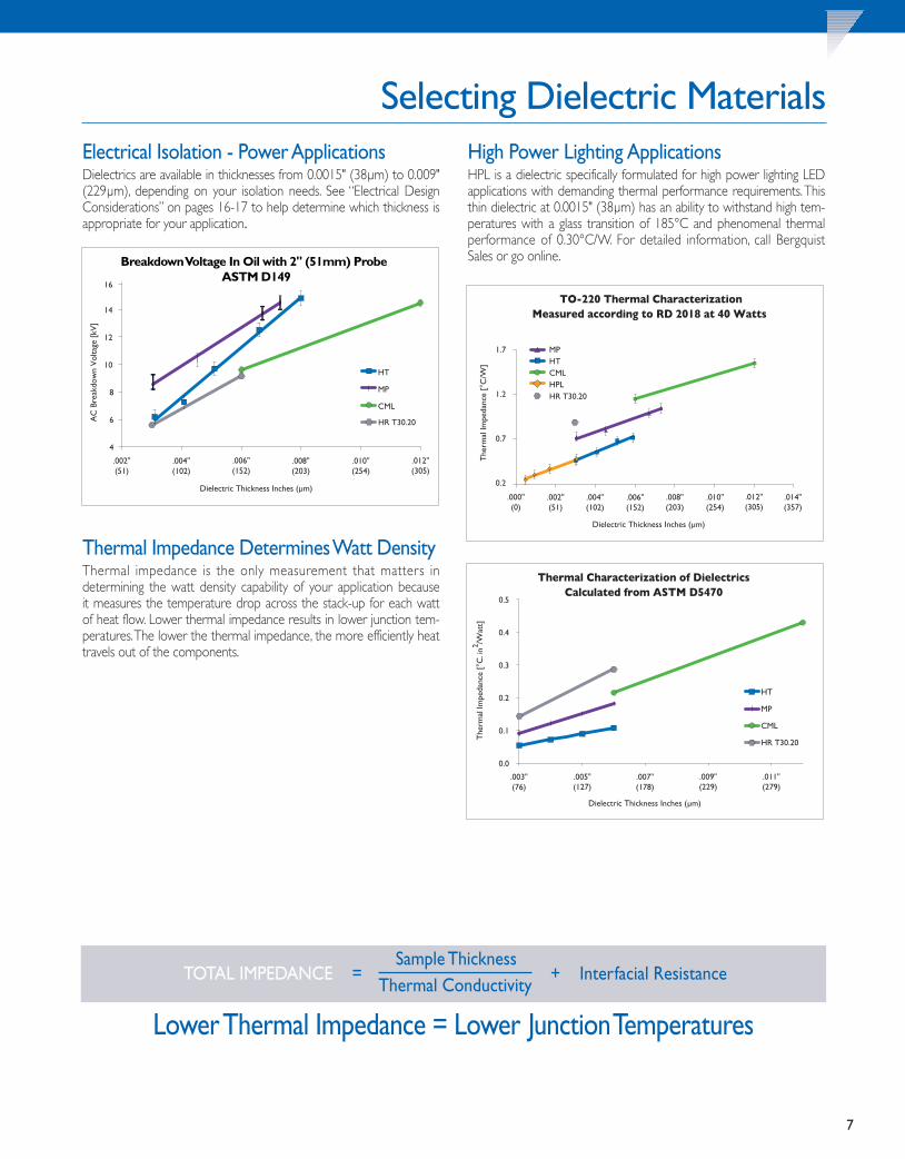
Selecting Dielectric Materials
Lower Thermal Impedance = Lower JunctionTemperatures
TOTAL IMPEDANCE =Sample Thickness
+ Interfacial ResistanceThermal Conductivity
Electrical Isolation - Power ApplicationsDielectrics are available in thicknesses from 0.0015" (38µm) to 0.009"(229µm), depending on your isolation needs. See “Electrical DesignConsiderations” on pages 16-17 to help determine which thickness isappropriate for your application.
Thermal Impedance Determines Watt DensityThermal impedance is the only measurement that matters in determining the watt density capability of your application because it measures the temperature drop across the stack-up for each wattof heat flow. Lower thermal impedance results in lower junction tem-peratures.The lower the thermal impedance, the more efficiently heattravels out of the components.
HHiigghheerr
High Power Lighting ApplicationsHPL is a dielectric specifically formulated for high power lighting LEDapplications with demanding thermal performance requirements.Thisthin dielectric at 0.0015" (38µm) has an ability to withstand high tem-peratures with a glass transition of 185°C and phenomenal thermalperformance of 0.30°C/W. For detailed information, call BergquistSales or go online.
TClad_DGguts_2013 v28.qxp 10/3/2013 10:29 AM Page 7

8
Coefficient of Thermal Expansion
This chart graphs the stability of the bond strength between the dielectric and the circuit layerduring temperature rise. Although bond strength goes down at higher temperatures, it main-tains at least 3 lbs/inch (0.53 N/mm) even at 175°C.
Thermomechanical Analysis (TMA) measures the dimensional stability of materials duringtemperature changes, monitoring the Coefficient of Thermal Expansion (CTE). Note: In theapplication, the CTE of the base material is a dominant contributor to thermalmechanical stress. See pages 12-13 for base layer selection.
CTE OF IMS BOARDS - The concerns in exceeding Tg in standard FR-4 materials from amechanical standpoint should be tempered when using Thermal Clad. The ceramic filler inthe polymer matrix of Thermal Clad dielectrics results in considerably lower Z-axis expansionthan in traditional FR-4 materials, while the low thickness of the dielectric means significantlyless strain on plated-through-hole (PTH) connections due to expansion.
This chart depicts the storage modulus of the material over a temperature range. All of our dielectrics are robust, but you will want to choose the one that best suits your operatingtemperature environment. See “Assembly Recommendations” on pages 18-19 for additionalinformation.
Peel Strength Storage Modulus
Operating Thermal Clad Materials Above TgAbove the Tg of the material, mechanical and electrical propertiesbegin to change. Mechanical changes of note are a reduction of peelstrength of the copper foil, an increase in the CTE, and decreasingstorage modulus.There is a potential benefit of relieving residual stresson the dielectric interfaces, in solder joints and other interconnectsdue to CTE mismatches by choosing a dielectric with Tg below theoperating temperature. The dielectric material above Tg is in its elas-tomeric state (much lower storage modulus), allowing some of thestresses to relax. Changes in electrical properties must also be consid-ered in operation above Tg, although they are typically only importantat frequencies above 1MHz. Effects to consider are changes in the per-mitivity, dielectric loss and breakdown strength of the material.Important Note: Many Thermal Clad products have U.L. rating up to45% higher than their glass transition temperature and are usedextensively in applications above rated Tg.
Dielectric Performance Considerations
TClad_DGguts_2013 v28.qxp 10/3/2013 10:29 AM Page 8
9
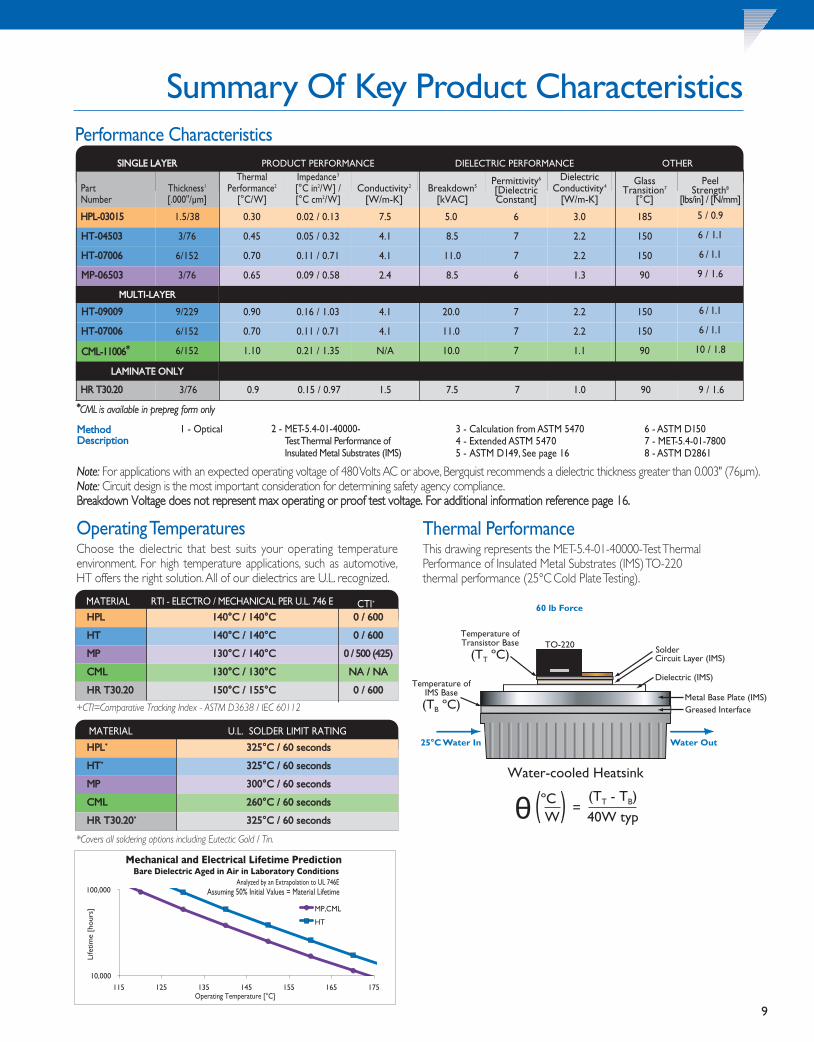
Summary Of Key Product Characteristics
RTI - ELECTRO / MECHANICAL PER U.L. 746 EMATERIAL
Operating TemperaturesChoose the dielectric that best suits your operating temperature environment. For high temperature applications, such as automotive,HT offers the right solution.All of our dielectrics are U.L. recognized.
HHPPLL 114400°°CC // 114400°°CC 00 // 660000
HHTT 114400°°CC // 114400°°CC 00 // 660000
MMPP 113300°°CC // 114400°°CC 00 // 550000 ((442255))
CCMMLL 113300°°CC // 113300°°CC NNAA // NNAA
HHRR TT3300..2200 115500°°CC // 115555°°CC 00 // 660000
Performance Characteristics
MMeetthhooddDDeessccrriippttiioonn
1 - Optical 2 - MET-5.4-01-40000-Test Thermal Performance ofInsulated Metal Substrates (IMS)
3 - Calculation from ASTM 54704 - Extended ASTM 54705 - ASTM D149, See page 16
6 - ASTM D1507 - MET-5.4-01-78008 - ASTM D2861
Note: For applications with an expected operating voltage of 480 Volts AC or above, Bergquist recommends a dielectric thickness greater than 0.003" (76µm).Note: Circuit design is the most important consideration for determining safety agency compliance.BBrreeaakkddoowwnn VVoollttaaggee ddooeess nnoott rreepprreesseenntt mmaaxx ooppeerraattiinngg oorr pprrooooff tteesstt vvoollttaaggee.. FFoorr aaddddiittiioonnaall iinnffoorrmmaattiioonn rreeffeerreennccee ppaaggee 1166..
Thermal PerformanceThis drawing represents the MET-5.4-01-40000-Test ThermalPerformance of Insulated Metal Substrates (IMS) TO-220 thermal performance (25°C Cold Plate Testing).
U.L. SOLDER LIMIT RATINGMATERIAL
*Covers all soldering options including Eutectic Gold / Tin.
Water-cooled Heatsink
TO-220 SolderCircuit Layer (IMS)
Dielectric (IMS)
Metal Base Plate (IMS) Greased Interface
25°C Water In Water Out
60 lb Force
Temperature of Transistor Base
(TT ºC)
Temperature of IMS Base (TB ºC)
θ (TT - TB)
40W typºC W ( ) =
SSIINNGGLLEE LLAAYYEERR PRODUCT PERFORMANCE DIELECTRIC PERFORMANCE OTHER
PartNumber
Thickness1
[.000"/µm]
ThermalPerformance2
[°C/W]
Impedance3
[°C in2/W] /[°C cm2/W]
Conductivity2
[W/m-K]Breakdown5
[kVAC]
Permittivity6
[DielectricConstant]
DielectricConductivity4
[W/m-K]
GlassTransition7
[°C]
PeelStrength8
[lbs/in] / [N/mm]
HHPPLL--0033001155 1.5/38 0.30 0.02 / 0.13 7.5 5.0 6 3.0 185 5 / 0.9
HHTT--0044550033 3/76 0.45 0.05 / 0.32 4.1 8.5 7 2.2 150 6 / 1.1
HHTT--0077000066 6/152 0.70 0.11 / 0.71 4.1 11.0 7 2.2 150 6 / 1.1
MMPP--0066550033 3/76 0.65 0.09 / 0.58 2.4 8.5 6 1.3 90 9 / 1.6
MMUULLTTII--LLAAYYEERR
HHTT--0099000099 9/229 0.90 0.16 / 1.03 4.1 20.0 7 2.2 150 6 / 1.1
HHTT--0077000066 6/152 0.70 0.11 / 0.71 4.1 11.0 7 2.2 150 6 / 1.1
CCMMLL--1111000066** 6/152 1.10 0.21 / 1.35 N/A 10.0 7 1.1 90 10 / 1.8
LLAAMMIINNAATTEE OONNLLYY
HHRR TT3300..2200 3/76 0.9 0.15 / 0.97 1.5 7.5 7 1.0 90 9 / 1.6
**CCMMLL iiss aavvaaiillaabbllee iinn pprreepprreegg ffoorrmm oonnllyy
HHPPLL** 332255°°CC // 6600 sseeccoonnddss
HHTT** 332255°°CC // 6600 sseeccoonnddss
MMPP 330000°°CC // 6600 sseeccoonnddss
CCMMLL 226600°°CC // 6600 sseeccoonnddss
HHRR TT3300..2200** 332255°°CC // 6600 sseeccoonnddss
CTI+
+CTI=Comparative Tracking Index - ASTM D3638 / IEC 60112
TClad_DGguts_2013 v28.qxp 10/3/2013 10:29 AM Page 9

Thermal Clad has replaced ceramics and DBC in applications due to mechanicalrobustness and its ability to be fabricated in a wide variety of form-factors.
10
Advanced Circuit ProcessingTwo-Layer Systems Using Thermal Clad CircuitsBergquist dielectrics are ideal for applications requiring a two-layersolution.Two-layer constructions can provide shielding protection andadditional electrical interconnects for higher component density.Bergquist dielectrics will provide superior thermal performance overtraditional FR-4 constructions. In addition, thermal vias can maximizethermal capabilities for applications utilizing power components.When vias can not be used, selecting higher performance dielectricscan solve thermal issues independently (see graph, below).
Bergquist has the ability to laminate heavycopper up to 5 oz. (175µm) finished on theinternal layer utilizing a thicker deposit of HTdielectric.
Close-up view of direct die attachment in anLED application. The Thermal Clad substrateis used to mount the die or module.
FR-4
FR-4
HT
HT HT
The graph depicts the modeled thermal result of various two-layer constructions as a func-tion of device case temperature. The emphasis is the thermal effect of proper vias utilization.
Direct Die ApplicationDirect die attach and wirebond are increasingly popular methods ofcomponent mounting to Thermal Clad substrates.A key benefit to thisstructure is lower thermal resistance as compared to conventional sur-face mount component packages soldered to an IMS substrate.
DBC ReplacementReplace Ceramic SubstratesThermal Clad can replace large-area ceramic substrates. It can also beused as a mechanically durable support for ceramic circuits or direct-bond copper subassemblies. The copper circuit layer of Thermal Cladhas more current carrying capability than thick-film ceramic technology.
Ultra Thin CircuitsUltra Thin Circuits (UTC) utilize T-Clad® dielectrics without the typicalthick base layer. These circuits are often used for component levelpackaging where the thick aluminum or copper base is not requiredfor mechanical or thermal mass. The circuit layer is a “stand-alone”ceramic submount replacement where the heat spreading and heatsinking is done in a different location. In addition, UTC can often beused for standard component package mounting. In some cases, thethermal performance and heat dissipation of the UTC is adequate toeliminate the need for heat sinking altogether. The total profile of aUTC can be as thin as 0.009" (0.23mm) and can be built up into multi-layer structures. This type of structure is also available with Bond-Ply450 thermally conductive PSA tape pre-applied to the back. See page15 for examples of this format.
Heavy CopperApplications requiring heavy copper for high current or heatspreading are not limited to single-layer needs.The ability to have inter-nal layers of heavy copper can provide greater applicationflexibility. Direct access to the internal copper layer to directly attach ormount components provides unique applications capability. Look foropportunities to reduce the copper thickness. In many applications,Bergquist T-Clad thermal performance reduces the need for heavy copper.
When designing circuits using Chip-On-Board (COB) technology it isimportant to use the appropriate surface finish to achieve excellentdie mounting and wire bond connections. The die attachment isaccomplished using SnPb, Pb-free solders, eutectic gold/tin solder or anelectrical/thermal conductive adhesive, depending on the applicationrequirements to adhere the die to the substrate.The wirebonding per-formed to make circuit connections is usually either gold or aluminum.ENEPIG (Electroless Nickel/Electroless Palladium/Immersion Gold) or Immersion Silver is recommended for gold wire and ENIG(Electroless Nickel/ Immersion Gold) for aluminum wire applications.HT dielectrics are U.L. solder rated at 325°C/60 seconds, enablingEutectic Gold/Tin solders.
Photographic example of UTC versus a standard 0.062" (1.57mm) aluminum substrate.
Thermal via’s usedin T-Clad 2 layersystem to maximize thermaldissipation.
TClad_DGguts_2013 v28.qxp 10/3/2013 10:29 AM Page 10
11
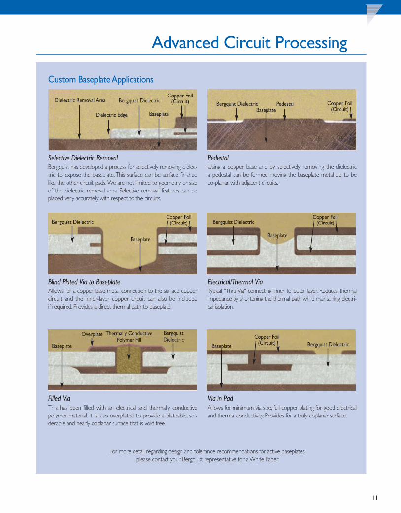
Advanced Circuit Processing
Electrical/Thermal ViaTypical "Thru Via" connecting inner to outer layer. Reduces thermalimpedance by shortening the thermal path while maintaining electri-cal isolation.
For more detail regarding design and tolerance recommendations for active baseplates,please contact your Bergquist representative for a White Paper.
Custom Baseplate Applications
PedestalUsing a copper base and by selectively removing the dielectric a pedestal can be formed moving the baseplate metal up to be co-planar with adjacent circuits.
Blind Plated Via to BaseplateAllows for a copper base metal connection to the surface coppercircuit and the inner-layer copper circuit can also be included if required. Provides a direct thermal path to baseplate.
Via in PadAllows for minimum via size, full copper plating for good electricaland thermal conductivity. Provides for a truly coplanar surface.
Filled ViaThis has been filled with an electrical and thermally conductivepolymer material. It is also overplated to provide a plateable, sol-derable and nearly coplanar surface that is void free.
Dielectric Removal Area
Dielectric Edge Baseplate
Bergquist DielectricCopper Foil
(Circuit) Copper Foil(Circuit)
PedestalBergquist DielectricBaseplate
Selective Dielectric RemovalBergquist has developed a process for selectively removing dielec-tric to expose the baseplate. This surface can be surface finishedlike the other circuit pads. We are not limited to geometry or sizeof the dielectric removal area. Selective removal features can beplaced very accurately with respect to the circuits.
Bergquist DielectricCopper Foil
(Circuit)
Baseplate
Bergquist DielectricCopper Foil
(Circuit)
Baseplate
Bergquist Dielectric
Baseplate
Overplate Thermally Conductive Polymer Fill
Baseplate
Copper Foil(Circuit) Bergquist Dielectric
TClad_DGguts_2013 v28.qxp 10/3/2013 10:29 AM Page 11

12
t CCooeeffffiicciieenntt OOff TThheerrmmaall EExxppaannssiioonnAAnndd HHeeaatt SSpprreeaaddiinngg
t CCooeeffffiicciieenntt OOff TThheerrmmaall EExxppaannssiioonnAAnndd SSoollddeerr JJooiinnttss
t SSttrreennggtthh,, RRiiggiiddiittyy AAnndd WWeeiigghhttt EElleeccttrriiccaall CCoonnnneeccttiioonnss TToo BBaasseeppllaatteet SSuurrffaaccee FFiinniisshht CCoossttss
Coefficient Of Thermal Expansion And Heat SpreadingThe adjacent graph depicts the CTE of the baseplate material in rela-tionship to the heat spreading capability of the metal. AlthoughAluminum and Copper are the most popular baseplates used inThermal Clad, other metals and composites have been used in applica-tions where CTE mismatch is a factor. The adjacent table representsstandard and non-standard baseplate materials.
Baseplate Design Considerations
Coefficient Of Thermal ExpansionAnd Solder JointsSolder joint fatigue can be minimized by selecting the correct baselayer to match component expansion.The major concern with ther-mal expansion is the stress the solder joint experiences in power (orthermal) cycling. Stress induced by heating and cooling may cause thejoint to fatigue as it absorbs stress. Large devices, extreme tempera-ture differential, badly mismatched materials, or lead-free minimumsolder thickness may all place increased cyclic strain on solder joints.
Solder joint fatigue is typically first associated with ceramic basedcomponents and with device termination. The section on “AssemblyRecommendations” (page 18-19) covers these issues in more detail.
Extra-Long CircuitsFinished circuits up to 26" (660mm) long
METAL / ALLOY
THERMALCONDUCTIVITY
[W/m-K]
COEFFICIENT OFTHERMAL EXPANSION
[ppm/K]DENSITY
[g/cc]
MODULUS OFRIGIDITY
[GPa]YIELD STRENGTH
[MPa]
CCooppppeerr 400 17 8.9 44.1 310
AAlluummiinnuumm 55005522 140 25 2.7 25.9 215
AAlluummiinnuumm 66006611 170 25 2.7 26 230
TClad_DGguts_2013 v28.qxp 10/3/2013 10:29 AM Page 12

13
Base ThicknessCopper and aluminum Thermal Clad is normally purchased in one ofthe standard-gauge thicknesses shown in the table below. Non-stan-dard thicknesses are also available.
Electrical Connections To BaseplateIf a connection to the base plate is desired, copper is the most com-patible base layer to use. When using electrical or thermal vias, it isimportant to match the circuit and base coefficients of thermal CTEexpansion as closely as possible. Otherwise, excessive stress to theplated-hole will occur during thermal cycles. Other base layer materi-als can be used for connection, but will require different connectionschemes.
CostsThe most cost effective base layers are aluminum and copperbecause they represent industry standards. Copper is more expensivethan aluminum when comparing the like thicknesses, but can be acompetitive option if design considerations allow for a thinner copperbase. As an example, typically the cost of 0.040" (1.0mm) copper isequal to the cost of 0.125" (3.2mm) aluminum.
Surface FinishAluminum and copper base layers come with a uniform commercialquality brushed surface. Aluminum is also available anodized or withother conversion coatings.
Standard Thermal Clad PanelsAvailable in:
• 18" (457mm) x 24" (610mm)Usable area: 17" (432mm) x 23" (584mm)
• 18" (457mm) x 25" (635mm)Usable area: 17" (432mm) x 24" (610mm)
• 20" (508mm) x 24" (610mm)Usable area: 19" (483mm) x 23" (584mm)
AAlluummiinnuumm -- TThhiicckknneesssseess
CCooppppeerr -- TThhiicckknneesssseess
*Standard thicknesses highlighted
IInncchheess MMiilllliimmeetteerrss
0.020 0.51
0.032 0.81
0.040 1.02
0.062 1.57
0.080 2.03
0.125 3.18
0.160 4.06
0.190 4.83
IInncchheess MMiilllliimmeetteerrss
0.020 0.51
0.031 0.79
0.040 1.02
0.060 1.52
0.080 2.03
0.125 3.18
TClad_DGguts_2013 v28.qxp 10/3/2013 10:29 AM Page 13

1" by 0.125" (25mm by 3.2mm) trace on 0.003" (76µm) HT dielectric
or 0.006" (152µm) FR-4 dielectric
10 9 8 7 6 5 4 3 2 1
5 10 15 20 25
HT
1 oz (35µm) 2 oz (70µm)
1 oz (35µm) 2 oz (70µm)
Relative temperature rise comparison graph depicts the significant difference betweenBergquist Dielectric HT and FR-4. Additional comparison charts regarding all BergquistDielectrics are available. Note: No base metal used in calculation.
14
t CCuurrrreenntt CCaarrrryyiinngg CCaappaabbiilliittiieesst HHeeaatt SSpprreeaaddiinngg CCaappaabbiilliittiieess
Current Carrying CapabilitiesThe circuit layer is the component-mounting layer in Thermal Clad.Current carrying capability is a key consideration because this layertypically serves as a printed circuit, interconnecting the componentsof the assembly. The advantage of Thermal Clad is that the circuittrace interconnecting components can carr y higher currentsbecause of its ability to dissipate heat due to I2R loss in the coppercircuitry.
Selecting A Circuit Layer
50
40
30
20
10
0 0 50 100 200 250 150
1" by 0.125" (25mm by 3.2mm) trace on 0.003" (76µm) HT dielectric
or 0.006" (152µm) FR-4 dielectric HT
1 oz (35µm) 3 oz (105µm) 6 oz (210µm) 10 oz (350µm)
1 oz (35µm) 3 oz (105µm) 6 oz (210µm) 10 oz (350µm)
Temperature rise comparison graph depicts the significant difference between BergquistDielectric HT and FR-4. Additional comparison charts regarding all Bergquist Dielectrics areavailable. Note: No base metal used in calculation.
Want a cost effective,optimized circuit design?This Thermal Clad White Paper addresses specific design recommendations including mechanical, circuit, soldermask, fabrication and test options to help optimize your design.
TClad_DGguts_2013 v28.qxp 10/3/2013 10:30 AM Page 14

15
Standard Circuit Layer Thickness
Heat Spreading CapabilityDielectric thickness and foil thickness both influence heat spreadingcapability in Thermal Clad. Heat spreading is one of the most powerfuladvantages derived from IMS. By increasing copper conductor thick-ness, heat spreading increases and brings junction temperature down.In some cases very heavy copper can be utilized along with bare dieto eliminate the need for a standard packaged component.
The following graphs depict both the thermal impedance value andcase temperature when relating dielectric and foil thickness.
40 Watt TO-220 soldered to 1" by 1" (25mm x 25mm)Thermal Clad MP
Bergquist RD2018 Test Method
Dielectric Thickness Inches (µm )
.002"(51)
1 oz (35µm) circuit foil
3 oz (105µm) circuit foil
6 oz (210µm) circuit foil
10 oz (350µm) circuit foil
.003"(76)
.004"(102)
.005"(127)
.006"(152)
.007"(178)
40 Watt TO-220 soldered to 1" by 1" (25mm x 25mm)Thermal Clad MP
Bergquist RD2018 Test Method
Dielectric Thickness Inches (µm)
.002"(51)
.003"(76)
.004"(102)
.005"(127)
.006"(152)
.007"(178)
1 oz (35µm) circuit foil
3 oz (105µm) circuit foil
6 oz (210µm) circuit foil
10 oz (350µm) circuit foil
The
rmal
Impe
danc
e[°C
/W]
NOTE: Copper foil is NOT measured for thickness as a control method. Instead, it is certified to an area weight requirement per IPC-4562. The nominalthickness given on 1 oz. copper is 0.0014" (35 µm).
CAUTION! Values in IPC-4562 (Table 1.1) are not representative of mechanical thickness.
Ultra Thin Circuits utilizing Bond-Ply® 450 PA. See pages 10 and 18 for additional information.
MATERIAL WEIGHT REFERENCE THICKNESS(oz/ft2) inches µm
Copper(Zinc Treatment)
0.5 0.0007 181 0.0014 352 0.0028 703 0.0042 1054 0.0056 1405 0.0070 1756 0.0084 2108 0.0112 28010 0.0140 350
TClad_DGguts_2013 v28.qxp 10/3/2013 10:30 AM Page 15

16
“Proof Test” fixture to test multiple number of finished circuit boards at one time.
t PPrrooooff TTeessttiinnggt BBrreeaakkddoowwnn VVoollttaaggeet CCrreeeeppaaggee DDiissttaannccee AAnndd DDiisscchhaarrggee
Proof TestThe purpose of "Proof Testing" Thermal Clad substrates is to verifythat no defects reside in the dielectric material. Because testingrequires that voltages be above the onset of partial discharge, we rec-ommend the number of “Proof Tests” be kept at a minimum.
The term "Partial Discharge" includes a broad spectrum of life reducing (i.e. material damaging) phenomena such as:
1. Corona discharge2. Treeing and surface tracking contamination3. Surface discharges at interfaces, particularly during fault
induced voltage reversal4. Internal discharges in voids or cavities within the dielectric
Electrical Design Considerations
The purpose of the “Proof Test” is to verify that there has been nodegradation of the dielectric insulation due to the fabrication processor any material defects. Continued testing at these voltage levels willonly take away from the life of the dielectric on the circuit board. Ithas been repeatedly verified that “Proof Testing” above the inceptionof partial discharge (700 VAC or 1200 VAC with proper use of soldermask) will detect any and all defects in the dielectric isolation inthe Thermal Clad circuit board. Any micro-fractures, delaminations ormicro-voids in the dielectric will breakdown or respond as a shortduring the test.
The use of a DC “Proof Test” is recommended, from an operatorsafety standpoint. The voltage levels typically used are 1500 to 2250VDC. Due to the capacitive nature of the circuit board construction,it is necessary to control the ramp up of the voltage to avoid nui-sance tripping of the failure detect circuits in the tester and to main-tain effective control of the test. This is to avoid premature surfacearcing or voltage overshoot. There is safety consideration when DCtesting, in that the operator must verify the board tested is fully dis-charged, prior to removing from the test fixture. A more detailed dis-cussion of “Proof Test” is available upon request.
Breakdown VoltageThe ASTM D149 definition of dielectric breakdown voltage is: thepotential difference at which dielectric failure occurs under prescribedconditions in an electrical insulating material located between twoelectrodes. This is permanent breakdown and is not recoverable.ASTM goes on to state that the results obtained by this test can seldombe used directly to determine the dielectric behavior of a material inan actual application. This is not a test for “fit for use” in theapplication, as is the “Proof Test”, which is used for detection offabrication and material defects to the dielectric insulation.
Due to circuit board construction and layout, it is always recommendedto “Proof Test” at a value which is less than 50% of the specified ASTMD149 dielectric breakdown voltage. This should include provisions forcreepage distance to avoid surface arcing to the metal base.
TClad_DGguts_2013 v28.qxp 10/3/2013 10:30 AM Page 16

17
FOR POSITION ONLY
Typical Flashover Voltage in Various Media 0.003" (76µm) Dielectric, 25mm circular electrodes
Typical Flashover Voltage in Various Media 0.006" (152µm) Dielectric, 25mm circular electrodes
Creepage Distance And DischargeCreepage distance and discharge has to be taken into accountbecause Thermal Clad dielectrics often incorporate a metal base layer.Circuit board designers should consider “Proof Testing” requirementsfor: conductor-to-conductor and conductor-to-circuit board edge orthrough holes. The graphs below depict flashover : without solder-mask, with soldermask and under oil.
Leakage Current HiPot TestingDue to the variety of dielectric types, thicknesses and board layouts,not all boards test alike.All insulated metal substrates closely resemblea parallel plate capacitor during HiPot testing. Capacitance is equal to:
C = A/dwhere: = Permittivity (Dielectric Constant)A = Surface Aread = Distance (Dielectric Thickness)
The capacitance value changes with different configurations of materi-als and board layouts. This can be demonstrated where one boardfails the test and another passes, but when both are actually tested fordielectric strength and leakage current in a controlled environment,both pass.Therefore, it is very important to properly design the test-ing and test parameters with the material characteristics in mind.Testset-up and parameters that over-stress or do not consider reactanceof the material and its capacitive and resistive components, can leadto false failures and/or test damage of the board.
Another test characteristic that is generally misunderstood with insulated metal substrates is the leakage and charge current that takeplace during the test. In most cases, the leakage current value on insulated metal substrates is much smaller than the measurementcapability of a typical HiPot tester. What is most misunderstood is thecharge current that takes place during the test. Leakage current measurements can only be realized once the board has been broughtto the full test voltage (DC voltage) and is held at that voltage duringthe test. This current value and rate di/dt is directly related to thecapacitance of the board. Therefore, a board that has an effectivecapacitance higher than another board will have a higher charge current rate than the one with a lower effective capacitance. Thisdoes not reflect the leakage current or the voltage withstand of thedielectric insulation instead, it represents the characteristic transientresponse of the dielectric. Therefore, one is not able to determinecomparable leakage current based on the instantaneous charge current. For accurate leakage test data, bring the board up to full DCtest voltage and hold.
MEASURED CURRENT - CHARGE CURRENT = LEAKAGE CURRENT
TClad_DGguts_2013 v28.qxp 10/3/2013 10:30 AM Page 17

18
Solder AssemblySolder joints deserve additional consideration in the design of ThermalClad assemblies.This section covers solder surface finishes, applicationand thickness, alloy and flux.
Surface FinishesStandard circuit board finishes are available for Thermal Clad circuit boards.• ENIG (Electroless Nickel/Immersion Gold)• ENEPIG (Electroless Nickel/Electroless Palladium/Immersion Gold)• OSP (Organic Solderability Protectant)• Immersion Silver or Immersion Tin• Lead-Free HASL or Standard Tin/Lead HASL• Electrolytic Gold - for edge connectors
Application and Thickness - Solder PasteWith the majority of applications now requiring lead-free solder-ing, there are still some specialized applications using the Tin-Lead solder paste. In either case, the final solder joint is key tolong-term reliability.The solder joint thickness, component align-ment and solder fillet requirements should comply with theindustry standard: IPC-A-610 "Acceptability of ElectronicAssemblies". The section on solder joints for surface mountassemblies provides the information on acceptance criteria forsolder joints. It also describes defects that will require rework tomeet acceptance levels.
Note:Additional thickness and/or larger stencil opening may need to be utilized for RoHS compliance applications.Use profile recommended by thecomponent manufacturer.
Assembly Recommendations
Now AvailableT-Clad Bond-Ply 450 PAThermal Clad with Bond-Ply 450 PA is a thermally conductive adhesive tape that features a release liner on the back side for easy removal and application to a heat sink. T-Clad PA substrate release liners can withstand high temperatures and will maintain adhesion and release characteristics even after exposure to the extreme heat of solder reflow. For a complete data sheet, contact Bergquist Sales.Wire soldering on Thermal Clad.
Your most popular LED footprints are available through distribution.Contact Bergquist Sales for more information.
TClad_DGguts_2013 v28.qxp 10/3/2013 10:30 AM Page 18

19
Connection TechniquesConnection techniques common throughout the industry are beingused successfully on Thermal Clad IMS substrates. Surface mountconnectors are manufactured using plastic molding materials withthermal coefficients of expansion that roughly match the characteris-tics of the baseplate metal. However, the plastic molding compoundsdo have a different thermal capacity and thermal conductivity thatcan cause stress in the assembly as it cools after soldering and duringany significant temperature excursion. Process-caused thermal mechani-cal stress is specific to the solder reflow process used. For this reason,designs that capture the metal pin without rigidity are preferred, partic-ularly if the major dimension of the connector is large.
Pin ConnectorsPin connectors and pin headers are often used in Thermal Cladassembly when an FR-4 panel is attached to a Thermal Clad assembly.The differential coefficient of expansion between the control panel andthe base metal will cause stress in the solder joint and dielectric.Themost advanced designs incorporate stress relief in the fabrication ofthe pin. Redundant header pins are often used to achieve high currentcarrying capacity.
Manufacturers such as AutoSplice andZierick have off the shelf pins ideal for IMS applications. Custom pins and connectors arealso available.
Custom ConnectorsIn the example above, the application required a large cable connec-tion to the T-Clad IMS board. Precautions were taken for the bestelectrical connection with minimized mechanical strain on the etchedcircuit. This solution addresses both electrical and mechanical fasten-ing. The small holes allow for complete void-free soldering. Also, theinsulated shoulder washer prevents shorting to the base plate.Thesetypes of connectors are usually custom made and are not commer-cially available.
Wire Bonding – Direct Die AttachWire bonding is par ticularlyuseful in the design of packageswith Chip-On-Board (COB)architecture. This techniqueuses the surface mount andinterconnect capabi l i ty ofThermal Clad in a highly effi-c ient thermal design. Seepage 10 for additional infor-mation.Power Connections
Only a few companies supply spade or threaded fastener con-nectors for surface mount power connections. In many cases theseare lead frame assemblies soldered to the printed circuit pads andbent to accommodate the shell used for encapsulation. Designs incor-porating stress relief and a plastic retainer suitable for high amperageare also available. Thru-board connectors will require adherance tofabrication design rules for IMS PWB’s.
Edge ConnectorsWhen using edge connectors as part of the Thermal Clad printedwiring pattern, it is suggested that interfacing conductors be finishedwith an electrolytic hard gold plating over sulfamate nickel plating.A 45° chamfer is recommended when using an edge connector.Remember to maintain the minimum edge to conductor distance toprevent shorting. Flex attachment on Thermal Clad.
This Tyco ElectronicsTM SMT thru-board connector provides a way to bring powerfrom the underside of a Thermal Clad IMSboard, eliminating issues of dressing wires onthe top side of LED boards.
Close up view of a direct die attachmentin a power application.
TClad_DGguts_2013 v28.qxp 10/3/2013 10:31 AM Page 19

20
Sil-Pad®
Sil-Pad is the benchmark in thermal interface materials. The Sil-Pad family of materialsare thermally conductive and electrically insulating. Available in custom shapes, sheets,and rolls, Sil-Pad materials come in a variety of thicknesses and are frequently used inSMT applications such as:
• Interface between thermal vias in a PCB, and a heat sink or casting• Heat sink interface to many surface mount packages
Hi-Flow®
The Hi-Flow family of phase change materials offers an easy-to-apply thermal interfacefor many surface mount packages. At the phase change temperature, Hi-Flow materialschange from a solid and flow with minimal applied pressure.This characteristic optimizesheat transfer by maximizing wet-out of the interface. Hi-Flow is commonly used toreplace messy thermal grease.
Bergquist phase change materials are specially compounded to prevent pump-out ofthe interface area, which is often associated with thermal grease.Typical applications forHi-Flow materials include:
• DC/DC converters • Power modulesHi-Flow materials are manufactured with or without film or foil carriers.Custom shapes and sizes for non-standard applications are also available.
MMiidd PPoowweerr AApppplliiccaattiioonn wwiitthh BBoonndd--PPllyy oorr SSiill--PPaadd
Power Device
Sil-Pad orBond-Ply FR-4
HHiigghh PPoowweerr AApppplliiccaattiioonn HHii--FFllooww wwiitthhoouutt TThheerrmmaall CCllaadd
HHiigghh PPoowweerr AApppplliiccaattiioonn HHii--FFllooww wwiitthh TThheerrmmaall CCllaadd
Power Device
Processor
Thermal Clad
Hi-Flow
Hi-FlowHeatSpreader
HeatSpreader
FR-4 Board
HeatSpreader
Solutions For Surface-Mount Applications
TClad_DGguts_2013 v28.qxp 10/3/2013 10:31 AM Page 20

21
Bond-Ply® and Liqui-Bond®
The Bond-Ply family of materials are thermally conductive and electrically isolating.Bond-Ply is available in a pressure sensitive adhesive or laminating format. Bond-Ply pro-vides for the mechanical decoupling of bonded materials with mismatched thermalcoefficients of expansion. Liqui-Bond is a high thermal performance liquid silicone adhe-sive that cures to a solid bonding elastomer.Typical applications include:
• Bonding bus bars in a variety of electronic modules and sub assemblies• Attaching a metal-based component to a heat sink• Bonding a heat sink to a variety of ASIC, graphic chip, and CPU packages• Bonding flexible circuits to a rigid heat spreader or thermal plane• Assembly tapes for BGA heat spreader• Attaching PCB assemblies to housings
Gap Pad® and Gap FillerThe Gap Pad product family offers a line of thermally conductive materials, in pad or liquid dispensable format, which are highly conformable. Varying degrees of thermal conductivity and compression deflection characteristics are available.Typical applicationsinclude:
• On top of a semiconductor package such as a QFP or BGA. Often times, severalpackages with varying heights can use a common heat sink when utilizing Gap Pad.
• Between a PCB or substrate and a chassis, frame, or other heat spreader• Areas where heat needs to be transferred to any type of heat spreader• For interfacing pressure sensitive devices• Filling various gaps between heat-generating devices and heat sinks or housingsGap Pads are available in thickness of 0.010" (0.254mm) to 0.250" (6.35mm), and in cus-tom shapes, with or without adhesive. Gap Fillers are available in cartridge or kit form.
LLoowweerr PPoowweerr AApppplliiccaattiioonnwwiitthh GGaapp PPaadd
Gap Pad or Gap FillerPowerDevice
HeatSpreader
FR-4 Board
Where Thermal Solutions Come Together
The Path You Take Is YoursBergquist’s full line of liquid polymers make it easy to customize your material, pattern, volume and speed.Bergquist’s advanced liquids are specifically designed tosupport optimized dispensing control with excellentthermal conductivity. Dispensed in a liquid state thematerial creates virtually zero stress on components. Itcan be used to interface and conform to the mostintricate topographies and multi-level surfaces.
TClad_DGguts_2013 v28.qxp 10/3/2013 10:31 AM Page 21

22
D 149 Test Methods for Dielectric Breakdown Voltage and Dielectric Strength of Solid Electrical Insulating Materials at Commercial Power Frequencies
D 150 Test Methods for AC Loss Characteristics and Permittivity (Dielectric Constant)of Solid Electrical Insulating Materials
D 257 Test Methods for DC Conductance or Impedance of Insulating Materials
D 374 Test Methods for Thickness of Solid Electrical Insulation
D 3165 Test Method for Strength Properties of Adhesives in Shear by Tension Loading of Single-Lap-Joint Laminated Assemblies
D 5470 Test Methods for Thermal Transmission Properties of Thin Thermally Conductive Solid Electrical Insulating Materials
60093 Methods of test for volume resistivity and surface resistivity ofsolid electrical insulating materials
60243-1 Methods of test for electric strength of solid insulating materials -Part 1:Tests at power frequencies
60250 Recommended methods for the determination of the permittivity anddielectric dissipation factor of electrical insulating materials at power,audio, and radio frequencies including metre wavelengths
60626-2 Combined flexible materials for electrical insulation-Part 2: Methods of test
2221 Generic Standard on Printed Board Design
6012 Qualifications and Performance Specification of Rigid Printed Boards
600 Acceptance of Printed Boards
TM-650 Cleanliness (2.3.35 & 2.3.26)
TM-650-2.4.22 Bow and Twist
TM-650-2.4.8 Peel
SM-840 Soldermask
IPC-A610 Acceptability of Electronic Assemblies
IPC-7351 Generic requirements for Surface Mount Design and Land Pattern Standards
Adhesives Determination of tensile lap-shear strength of rigid-to-rigidbonded assemblies
AASSTTMM
IIPPCC
IIEECC
IISSOO 44558877
SSuurrffaacceeMMoouunntt
Appendix
TClad_DGguts_2013 v28.qxp 10/3/2013 10:31 AM Page 22

23
Thermal Clad Configurations
Custom CircuitBergquist Thermal Clad substrates are custom configured to yourdesign parameters at our Prescott,Wisconsin facility. Our field applica-tion support personnel in conjunction with our mechanical andprocess engineers are available to assist you in taking your design frompaper to finished product. Engineering is available for the followingconstruction parameters and options.
• Artwork layout recommendations• Base metal requirements and mechanical configuration• Dielectric thickness• Copper weights (18-350µm / .5-10 oz)• Solder mask layouts• All common circuit finishes• Tooling/singulation options
Panel FormAdditional base metal sizes and thickness options are available
Dimensions:• 18" x 24" (457mm x 610mm)
18" x 25" (457mm x 635mm)20" x 24" (508mm x 610mm)
• Foil Thickness: 18-350µm (.5-10 oz)
Base Plate Metals:• Aluminum 6061-T6, 5052-H34, standards
from 0.020" to 0.190" (0.5mm to 4.83mm)• Copper 110 Full-Hard, standard from
0.020" to 0.125" (0.5mm to 3.2mm)
Sheet And Roll FormatCML (Circuit Material Laminate) is a ceramic filled polymer that formsa strong, thermally conductive bond to metal heat spreaders and is anexcellent alternative to pre-preg.
• 24" (610mm) Roll Standard (custom sizes are available)• Maximum roll length of 2000' (610m)• Sheets 18"x 24" (457mm x 610mm)
and 20" x 24" (508mm x 610mm)
U.L.Certifications DirectoryThe U.L. website provides the latest information regarding the U.L.recognition status of Bergquist Thermal Clad materials and “PrescottOperations” circuit fabrication.
Using the address: http://www.ul.com, select Online CertificationsDirectory. Enter “Bergquist” into the “Company Name” field and pressthe search button. Click on the link of one of the two U.L. FileNumbers to view it: QMTS2.E121882 and ZPMV2.E122713.
• In each group there is guide information which will give a further description of the categories listed.
• In each group the recognized materials or fabricated circuitboard types will be listed.
QMTS2.E121882Polymeric Materials - Filament-wound tubing, IndustrialLaminates, Vulcanized Fiber, and Materials for Use inFabricating Recognized Printed Wiring Boards - Components.
ZPMV2.E122713Wiring, Printed - Component
TClad_DGguts_2013 v28.qxp 10/3/2013 10:31 AM Page 23

Notes
TClad_DGguts_2013 v28.qxp 10/3/2013 10:31 AM Page 24

TCDG_Cover_2013 v9.qxp 8/22/2013 11:38 AM Page 1

TCDG_0813
Corporate Headquarters and Sales Office:18930 West 78th StreetChanhassen, MN 55317
Circuits Manufacturing Facility:1600 Orrin Road
Prescott, WI 54021
Toll Free: (800) 347-4572 • Main: (952) 835-2322 • Fax: (952) 835-0430 • www.bergquistcompany.com
Thermal Products • Thermal Substrates • Fans and Blowers
DOMESTIC AGENTSFor a complete list of Bergquist sales representatives in the U.S. contact The Bergquist Company: 1-800-347-4572.
INTERNATIONAL SALES OFFICESCHINA
Tel: 86-755-3320-9328Fax: 86-755-3320-9323
GERMANYTel: 49-4101-803-230Fax: 49-4101-803-100
HONG KONGAsian HeadquartersTel: 852-2690-9296Fax: 852-2690-3408
THE NETHERLANDSEuropean HeadquartersTel: 31-35-5380684 Fax: 31-35-5380295
SOUTH KOREATel: 82-31-448-0382 Fax: 82-31-448-0383
AUSTRALIAAUSTRIABELGIUMBRAZILCANADACHINADENMARKFINLANDFRANCE
HOLLANDHONG KONGISRAELITALYJAPANMALAYSIAMEXICONEW ZEALANDNORWAY
PORTUGALRUSSIASINGAPORESPAINSWEDENSWITZERLANDTAIWANTHAILANDTURKEY
INTERNATIONAL AGENTS
TCDG_Cover_2013 v9.qxp 8/22/2013 11:38 AM Page 2