
TCA-1MEG High Impedance Buffer Amplifier Instruction … · are owned by Tektronix or its...
68
Instruction Manual TCA-1MEG High Impedance Buffer Amplifier 071-1010-01 Warning The servicing instructions are for use by qualified personnel only. To avoid personal injury, do not perform any servicing unless you are qualified to do so. Refer to all safety summaries prior to performing service. www.tektronix.com
Transcript of TCA-1MEG High Impedance Buffer Amplifier Instruction … · are owned by Tektronix or its...

Instruction Manual
TCA-1MEG
High Impedance Buffer Amplifier
071-1010-01
Warning
The servicing instructions are for use by qualifiedpersonnel only. To avoid personal injury, do notperform any servicing unless you are qualified todo so. Refer to all safety summaries prior toperforming service.
www.tektronix.com

Copyright © Tektronix, Inc. All rights reserved. Licensed software products
are owned by Tektronix or its subsidiaries or suppliers, and are protected by
national copyright laws and international treaty provisions.
Tektronix products are covered by U.S. and foreign patents, issued and
pending. Information in this publication supercedes that in all previously
published material. Specifications and price change privileges reserved.
TEKTRONIX and TEK are registered trademarks of Tektronix, Inc.
Contacting Tektronix
Tektronix, Inc.
14200 SW Karl Braun Drive
P.O. Box 500
Beaverton, OR 97077
USA
For product information, sales, service, and technical support:
In North America, call 1-800-833-9200.
Worldwide, visit www.tektronix.com to find contacts in your area.

Warranty 2
Tektronix warrants that this product will be free from defects in materials andworkmanship for a period of one (1) year from the date of shipment. If any such productproves defective during this warranty period, Tektronix, at its option, either will repair thedefective product without charge for parts and labor, or will provide a replacement inexchange for the defective product. Parts, modules and replacement products used byTektronix for warranty work may be new or reconditioned to like new performance. Allreplaced parts, modules and products become the property of Tektronix.
In order to obtain service under this warranty, Customer must notify Tektronix of thedefect before the expiration of the warranty period and make suitable arrangements for theperformance of service. Customer shall be responsible for packaging and shipping thedefective product to the service center designated by Tektronix, with shipping chargesprepaid. Tektronix shall pay for the return of the product to Customer if the shipment is toa location within the country in which the Tektronix service center is located. Customershall be responsible for paying all shipping charges, duties, taxes, and any other charges forproducts returned to any other locations.
This warranty shall not apply to any defect, failure or damage caused by improper use orimproper or inadequate maintenance and care. Tektronix shall not be obligated to furnishservice under this warranty a) to repair damage resulting from attempts by personnel otherthan Tektronix representatives to install, repair or service the product; b) to repair damageresulting from improper use or connection to incompatible equipment; c) to repair anydamage or malfunction caused by the use of non-Tektronix supplies; or d) to service aproduct that has been modified or integrated with other products when the effect of suchmodification or integration increases the time or difficulty of servicing the product.
THIS WARRANTY IS GIVEN BY TEKTRONIX WITH RESPECT TO THEPRODUCT IN LIEU OF ANY OTHER WARRANTIES, EXPRESS OR IMPLIED.TEKTRONIX AND ITS VENDORS DISCLAIM ANY IMPLIED WARRANTIES OFMERCHANTABILITY OR FITNESS FOR A PARTICULAR PURPOSE.TEKTRONIX’ RESPONSIBILITY TO REPAIR OR REPLACE DEFECTIVEPRODUCTS IS THE SOLE AND EXCLUSIVE REMEDY PROVIDED TO THECUSTOMER FOR BREACH OF THIS WARRANTY. TEKTRONIX AND ITSVENDORS WILL NOT BE LIABLE FOR ANY INDIRECT, SPECIAL, INCIDENTAL,OR CONSEQUENTIAL DAMAGES IRRESPECTIVE OF WHETHER TEKTRONIXOR THE VENDOR HAS ADVANCE NOTICE OF THE POSSIBILITY OF SUCHDAMAGES.


TCA-1MEG High Impedance Buffer Amplifier Instruction Manual i
Table of Contents
General Safety Summary v. . . . . . . . . . . . . . . . . . . . . . . . . . . . . .Service Safety Summary vii. . . . . . . . . . . . . . . . . . . . . . . . . . . . . .Environmental Considerations ix. . . . . . . . . . . . . . . . . . . . . . . . .
Preface xi. . . . . . . . . . . . . . . . . . . . . . . . . . . . . . . . . . . . . . . . . . . .Manual Structure xi. . . . . . . . . . . . . . . . . . . . . . . . . . . . . . . . . . . .Manual Conventions xii. . . . . . . . . . . . . . . . . . . . . . . . . . . . . . . . .
Getting Started 1. . . . . . . . . . . . . . . . . . . . . . . . . . . . . . . . . . . . .Product Description 1. . . . . . . . . . . . . . . . . . . . . . . . . . . . . . . . . .Accessories 3. . . . . . . . . . . . . . . . . . . . . . . . . . . . . . . . . . . . . . . .Input Voltage Derating 4. . . . . . . . . . . . . . . . . . . . . . . . . . . . . . . .Probe Calibration for High Accuracy 4. . . . . . . . . . . . . . . . . . . .Functionality Not Supported 5. . . . . . . . . . . . . . . . . . . . . . . . . .Installation 6. . . . . . . . . . . . . . . . . . . . . . . . . . . . . . . . . . . . . . . .Connecting the TCA-1MEG to the Host Instrument 6. . . . . . . .Connecting a Probe to the TCA-1MEG 8. . . . . . . . . . . . . . . . . .Attaching and Grounding a TCA-1MEG System 9. . . . . . . . . . .Functional Overview 10. . . . . . . . . . . . . . . . . . . . . . . . . . . . . . . . .Cleaning 12. . . . . . . . . . . . . . . . . . . . . . . . . . . . . . . . . . . . . . . . . . .
Functional Checks 13. . . . . . . . . . . . . . . . . . . . . . . . . . . . . . . . . .Prerequisites 13. . . . . . . . . . . . . . . . . . . . . . . . . . . . . . . . . . . . . . . .Required Equipment 14. . . . . . . . . . . . . . . . . . . . . . . . . . . . . . . . .Run the SPC (Signal Path Compensation)
on the Host Instrument 16. . . . . . . . . . . . . . . . . . . . . . . . . . . . .Calibrate the TCA-1MEG to the Host Instrument 16. . . . . . . . . .Calibrate the P6139A Passive Voltage Probe to the
TCA-1MEG and Host Instrument 18. . . . . . . . . . . . . . . . . . . .LF Probe Compensation 20. . . . . . . . . . . . . . . . . . . . . . . . . . . . . .Check Vertical Input Coupling 23. . . . . . . . . . . . . . . . . . . . . . . . .Check Bandwidth Limit 27. . . . . . . . . . . . . . . . . . . . . . . . . . . . . .
Specifications 31. . . . . . . . . . . . . . . . . . . . . . . . . . . . . . . . . . . . . .
Performance Verification 41. . . . . . . . . . . . . . . . . . . . . . . . . . . .TCA-1MEG System Bandwidth 42. . . . . . . . . . . . . . . . . . . . . . . .
Replaceable Parts 47. . . . . . . . . . . . . . . . . . . . . . . . . . . . . . . . . . .Parts Ordering Information 47. . . . . . . . . . . . . . . . . . . . . . . . . . . .Using the Replaceable Parts List 48. . . . . . . . . . . . . . . . . . . . . . . .

Table of Contents
ii TCA-1MEG High Impedance Buffer Amplifier Instruction Manual
List of Figures
Figure 1: TCA-1MEG High Impedance Buffer Amplifier 1. . . .Figure 2: Connecting and disconnecting the TCA-1MEG 7. . . .Figure 3: Calibration data message 7. . . . . . . . . . . . . . . . . . . . . .Figure 4: TekConnect and TEKPROBE Interface features 10. . . .Figure 5: Simplified block diagram 11. . . . . . . . . . . . . . . . . . . . .Figure 6: Probe Compensation Output of the TDS6604 15. . . . . .Figure 7: Setup with the P6139A attached to the TCA-1MEG 21Figure 8: Probe compensation waveforms 22. . . . . . . . . . . . . . . .Figure 9: Test equipment hookup for the Vertical
Input Coupling and Bandwidth Limit checks 23. . . . . . . . . . .Figure 10: Typical waveform at GND 24. . . . . . . . . . . . . . . . . . . .Figure 11: Typical waveform at AC Coupling 25. . . . . . . . . . . . .Figure 12: Typical waveform at DC Coupling 26. . . . . . . . . . . . .Figure 13: Typical waveform at Full (500 MHz) bandwidth 28. .Figure 14: Typical waveform at 100 MHz bandwidth 29. . . . . . .Figure 15: Typical waveform at 20 MHz bandwidth 30. . . . . . . .Figure 16: Typical Input Impedance and Phase
versus Frequency 33. . . . . . . . . . . . . . . . . . . . . . . . . . . . . . . . .Figure 17: Voltage Derating versus Frequency 34. . . . . . . . . . . . .Figure 18: TCA-1MEG dimensions 35. . . . . . . . . . . . . . . . . . . . .Figure 19: TCA-1MEG System Bandwidth equipment hookup 42Figure 20: TCA-1MEG replaceable parts 50. . . . . . . . . . . . . . . . .Figure 21: TCA-1MEG optional accessories 52. . . . . . . . . . . . . .

Table of Contents
TCA-1MEG High Impedance Buffer Amplifier Instruction Manual iii
List of Tables
Table 1: Compatible devices that require high impedance input 2Table 2: Required equipment 14. . . . . . . . . . . . . . . . . . . . . . . . . .Table 3: Warranted electrical specifications 31. . . . . . . . . . . . . .Table 4: Typical electrical characteristics 32. . . . . . . . . . . . . . . .Table 5: Physical characteristics 35. . . . . . . . . . . . . . . . . . . . . . .Table 6: Environmental characteristics 35. . . . . . . . . . . . . . . . . .Table 7: Certifications and compliances 36. . . . . . . . . . . . . . . . .Table 8: Equipment required for performance verification 41. . .

Table of Contents
iv TCA-1MEG High Impedance Buffer Amplifier Instruction Manual

TCA-1MEG High Impedance Buffer Amplifier Instruction Manual v
General Safety Summary
Review the following safety precautions to avoid injury and preventdamage to this product or any products connected to it. To avoidpotential hazards, use this product only as specified.
Only qualified personnel should perform service procedures.
To Avoid Fire or Personal Injury
Connect and Disconnect Properly. Connect the TCA-1MEG amplifier tothe host instrument, then connect the probe or other input device tothe TCA-1MEG. Connect the probe or other input device to thedevice-under-test.
Before disconnecting the TCA-1MEG from the host instrument,disconnect the probe or other input device, and the probe ground,from the device-under-test, and then disconnect the probe or otherinput device from the TCA-1MEG amplifier.
Ground the Product. This product is indirectly grounded through thegrounding conductor of the host instrument power cord. To avoidelectric shock, the grounding conductor must be connected to earthground. Before making connections to the input or output terminalsof the product, ensure that the product is properly grounded.
Observe All Terminal Ratings. To avoid fire or shock hazard, observe allratings and markings on the product. Consult the product manual forfurther ratings information before making connections to the product.
The common terminal is at ground potential. Do not connect thecommon terminal to elevated voltages.
Connect the ground lead of the probe to earth ground only.
Do Not Operate With Suspected Failures. If you suspect there is damageto this product, have it inspected by qualified service personnel.
Do Not Operate in Wet/Damp Conditions.
Do Not Operate in an Explosive Atmosphere.
Keep Product Surfaces Clean and Dry.

General Safety Summary
vi TCA-1MEG High Impedance Buffer Amplifier Instruction Manual
Provide Proper Ventilation. Refer to the manual’s installationinstructions for details on installing the product so it has properventilation.
Safety Terms and Symbols
Terms in This Manual. These terms may appear in this manual:
WARNING. Warning statements identify conditions or practices thatcould result in injury or loss of life.
CAUTION. Caution statements identify conditions or practices thatcould result in damage to this product or other property.
Terms on the Product. These terms may appear on the product:
DANGER indicates an injury hazard immediately accessible as youread the marking.
WARNING indicates an injury hazard not immediately accessible asyou read the marking.
CAUTION indicates a hazard to property including the product.
Symbols on the Product. These symbols may appear on the product:
CAUTION
Refer to Manual

TCA-1MEG High Impedance Buffer Amplifier Instruction Manual vii
Service Safety Summary
Only qualified personnel should perform service procedures. Readthis Service Safety Summary and the General Safety Summary beforeperforming any service procedures.
Do Not Service Alone.Do not perform internal service or adjustmentsof this product or host instrument unless another person capable ofrendering first aid and resuscitation is present.
Disconnect Power. To avoid electric shock, switch off the hostinstrument power, then disconnect the host instrument power cordfrom the mains power.
Use Care When Servicing with Power On.Dangerous voltages or currentsmay exist in this product and host instrument. Disconnect power,remove battery (if applicable), and disconnect test leads beforeremoving protective panels, soldering, or replacing components.
To avoid electric shock, do not touch exposed connections.

Service Safety Summary
viii TCA-1MEG High Impedance Buffer Amplifier Instruction Manual

TCA-1MEG High Impedance Buffer Amplifier Instruction Manual ix
Environmental Considerations
Product End-of-Life Handling
Observe the following guidelines when recycling an instrument orcomponent:
Equipment Recycling. Production of this equipment required theextraction and use of natural resources. The equipment may containsubstances that could be harmful to the environment or human healthif improperly handled at the product’s end of life. In order to avoidrelease of such substances into the environment and to reduce the useof natural resources, we encourage you to recycle this product in anappropriate system that will ensure that most of the materials arereused or recycled appropriately.
The symbol shown to the left indicates that thisproduct complies with the European Union’srequirements according to Directive 2002/96/ECon waste electrical and electronic equipment(WEEE). For information about recyclingoptions, check the Support/Service section of theTektronix Web site (www.tektronix.com).
Restriction of Hazardous Substances
This product has been classified as Monitoring and Controlequipment, and is outside the scope of the 2002/95/EC RoHSDirective. This product is known to contain lead, cadmium, mercury,and hexavalent chromium.

Environmental Considerations
x TCA-1MEG High Impedance Buffer Amplifier Instruction Manual

TCA-1MEG High Impedance Buffer Amplifier Instruction Manual xi
Preface
This is the Instruction manual for the TCA-1MEG High ImpedanceBuffer Amplifier. Read this preface to learn how this manual isstructured and what conventions it uses. Before using this manual orthe TCA-1MEG amplifier, read the General Safety Summary andService Safety Summary sections at the beginning of this manual forsafety and other important background information.
Manual Structure
This manual is divided into sections, which are made of relatedtopics:
Getting Started includes a product description, list of accessories,and instructions for installation.
Functional Checks includes procedures for verifying that theTCA-1MEG functions properly with a host instrument.
Specifications includes warranted electrical specifications, typicalelectrical characteristics, and graphs for typical input impedance,and typical bandwidth.
Performance Verification includes a procedure for verifyingwarranted electrical specifications.
NOTE. Service software for this instrument is included on theTDS Applications CD ROM (Tektronix part number 063--3376--XX)for your host instrument, and is also available for download from theTektronix Web site.
Be sure to read the introductory text for each procedure. Theseintroductions provide important information needed to use theTCA-1MEG High Impedance Buffer Amplifier correctly, safely, andefficiently.
Preface
xii TCA-1MEG High Impedance Buffer Amplifier Instruction Manual
Manual Conventions
The following conventions are used in this manual:
Safety
Symbols and terms related to safety appear in the Service SafetySummary found at the beginning of this manual.

TCA-1MEG High Impedance Buffer Amplifier Instruction Manual 1
Getting Started
Product Description
The TCA-1MEG is a High Impedance Buffer Amplifier system thatbroadens the functionality of a TekConnect host instrument. Featuresinclude:
Input impedance — 1 MΩ, 10 pF
Bandwidth — 500 MHz
Bandwidth limit (selectable) — Full (500 MHz), 100 MHz,and 20 MHz
Input coupling (selectable) — AC, DC, and GND
Input Connection — 1 MΩ TEKPROBE BNC
The TCA-1MEG amplifier, or other Tektronix TekConnect probesand adapters, enable you to easily configure each channel of yourhost instrument for the input characteristics you require.
To achieve a 1 MΩ system when you need it, use this amplifier toconnect a Tektronix 1 MΩ TEKPROBE BNC probe or other standard1 MΩ BNC accessory to your 50 Ω TekConnect host instrument. Toregain your high-speed, 50 Ω signal path, simply replace theTCA-1MEG with a high performance TekConnect probe or adapter.
Figure 1: TCA-1MEG High Impedance Buffer Amplifier

Getting Started
2 TCA-1MEG High Impedance Buffer Amplifier Instruction Manual
Table 1 lists Tektronix high-voltage passive probes, high-voltageactive probes, current probes, and other measurement analysis toolsthat require high impedance input. Use these devices with theTCA-1MEG to extend the use of your TekConnect host instrument.
Table 1: Compatible devices that require high impedance input
Device type Model Description
Passive voltage probes P6101B 15 MHz, 1X, passive
P6139A 500 MHz, 10X, passive
High voltage probes P6015A 20 kV, 1000X, 75 MHz,passive
P5100 2.5 kV, 100X, 250 MHz,passive
P5205 1.3 kV, 100 MHz, activedifferential
P5210 4.4 kV, 50 MHz, activedifferential
Micro-volt differential probe ADA400A 100X / 10X / 1X / 0.1Xpreamplifier
Current probes P6021 AC, 15 Ap--p, 60 MHz
P6022 AC, 6 Ap--p, 120 MHz
AM503S AC/DC current amplifiermeasurement system
Others Tektronixpart number012--0057--01
50 Ω BNC-to-BNC coaxialcable
Tektronixpart number011--0049--02
50 Ω feed through termina-tion
Tektronixpart number012--0482--00
50 Ω BNC-to-BNC coaxialcable, male to male

Getting Started
TCA-1MEG High Impedance Buffer Amplifier Instruction Manual 3
Accessories
The TCA-1MEG amplifier package has a set of standard accessories.
Standard Accessories for the TCA-1MEG
P6139A 10X Passive Probe with standard accessories andInstructions
Certificate of Traceable Calibration
TCA-1MEG High Impedance Buffer Amplifier Instruction Manual
(Tektronix part number 071-1010-XX)
TDS6000 Series Product Software (Tektronix part number063-3541-XX), also available on the Tektronix Web site
TDS7000 Series Product Software (Tektronix part number063-3461-XX), also available on the Tektronix Web site
Optional Accessories for the TCA-1MEG
Service software for the TCA-1MEG is included on the TDS Ap-plications Software CD for your host instrument. The CD is alsoavailable as an optional accessory for the TCA-1MEG (Tektronixpart number 063-3376-XX). The software is also available fordownload from the Tektronix Web site. The Tektronix websiteprovides up-to-date firmware and software upgrades.

Getting Started
4 TCA-1MEG High Impedance Buffer Amplifier Instruction Manual
Input Voltage Derating
The TCA-1MEG is designed to be used in a high voltage environ-ment. However, voltage input rating decreases as the frequency ofthe applied signal increases. Refer to Table 3 on page 31 of theSpecifications section for input voltage rating, and Figure 17 onpage 34 for voltage versus frequency derating information.
Probe Calibration for High Accuracy
To ensure high accuracy, a probe calibration routine is recommendedfor the TCA-1MEG:
When the ambient temperature changes by more than 5 °C(41 °F) from the temperature of the previous calibration
When you install the TCA-1MEG on a host instrument channelwhere it has not been calibrated previously
Refer to page 16 of the Functional Checks section for the probecalibration procedure.
Probes or adapters with the following characteristics will notcalibrate using the internal calibration signal of the TekConnect hostinstrument:
Probes or adapters without TEKPROBE readout capabilities
Probes with attenuation levels greater than 20X, due to the lowsignal level at the output of the internal calibration generator

Getting Started
TCA-1MEG High Impedance Buffer Amplifier Instruction Manual 5
Functionality Not Supported
50 Ω Termination at BNC input:
The TCA-1MEG amplifier does not provide a 50 Ω termination at itsBNC input. If you require 50 Ω termination for your applications,use a Tektronix TekConnect 50 Ω adapter (TCA-BNC, TCA-SMA,or TCA-N) in place of the TCA-1MEG. When the host instrumentdetects an incompatible device connected to the TCA-1MEG, itdisplays a message that an incompatible combination of accessorieshas been installed. The host instrument, however, will not detect allincompatible devices.
Readout and Power Connection Pins
The BNC connector of the TCA-1MEG is not compatible for usewith nonTektronix probes, cables, and adapters that have readout orpower connection pins.
CAUTION. To avoid damage to your equipment, do not use theTCA-1MEG with nonTektronix probes, cables, and adapters that havereadout or power connection pins.

Getting Started
6 TCA-1MEG High Impedance Buffer Amplifier Instruction Manual
Installation
The TCA-1MEG connects directly to the TekConnect interface onthe TekConnect host instrument.
Firmware RequirementsTo ensure compatibility of your TekConnect host instrument with theTCA-1MEG, your host instrument (for example, TDS6000,TDS7000, or CSA7000 series) must have the firmware upgradeV2.1.0 or higher.
CAUTION. To avoid instrument malfunctions, do not overwrite V2.1.0or higher firmware with an earlier version of firmware. Doing sowould require reinstallation of up-to-date firmware on the hostinstrument.
Firmware upgrade instructions are available on the CD ROMsincluded with the TCA-1MEG. The upgrades are also available onthe Tektronix Web site at www.tektronix.com. Select the Software &Drivers link on the home page of the Web site. The Tektronixwebsite provides up-to-date software and firmware upgrades.
Connecting the TCA-1MEG to the Host Instrument
The TekConnect Interface features a spring-loaded latch thatprovides audible and tactile confirmation that a reliable connectionhas been made to the TekConnect host instrument. Slide theTCA-1MEG into the TekConnect receptacle on the host instrument.The unit snaps into the host instrument when fully engaged. SeeFigure 2 on page 7.
To release the TCA-1MEG from the host instrument, grasp the unit,depress the latch button, and pull it out of the TekConnect receptacle.

Getting Started
TCA-1MEG High Impedance Buffer Amplifier Instruction Manual 7
Latch button
Figure 2: Connecting and disconnecting the TCA-1MEG
NOTE. If you connect the TCA-1MEG to a channel where it hasalready been probe calibrated, a message similar to the one shown inFigure 3, below, may appear on the display screen. Follow theinstructions on the message.
Figure 3: Calibration data message

Getting Started
8 TCA-1MEG High Impedance Buffer Amplifier Instruction Manual
Connecting a Probe to the TCA-1MEG
Before you connect a probe or other device, ensure that the device iscompatible with the TCA-1MEG. Refer to Functionality NotSupported on page 5 of the Getting Started section.
Follow the instructions in your probe manual for connecting yourprobe or other device to a TEKPROBE BNC connector.
NOTE. The maximum V/division setting with a 1X probe, or with noprobe, is 10 V/division. The Volts/division of the host instrument maychange when you connect probes with different attenuation factors.
Before connecting a probe or other device to the TCA-1MEG, alwaysrefer to the list of compatible devices in Table 1 on page 2.

Getting Started
TCA-1MEG High Impedance Buffer Amplifier Instruction Manual 9
Attaching and Grounding a TCA-1MEG System
Always use these procedures for safely connecting and dis-connecting the TCA-1MEG and probe to the circuit under test.
WARNING. To avoid fire or personal injury, connect the TCA-1MEGand probe output to the measurement instrument before connectingthe probe or other input device to the circuit under test. Disconnectthe probe input and probe ground from the circuit under test beforedisconnecting the probe or the TCA-1MEG from the measurementinstrument.
After connecting the TCA-1MEG to the host instrument andconnecting a probe to TCA-1MEG, connect the ground lead of theprobe to the ground of the circuit under test before taking anymeasurements.
Be careful that no part of the ground lead or probe grounding ringcontacts voltage in the circuit under test. Except for the probe tip andBNC center conductor, all accessible metal (including the groundclip) is connected to the BNC outer shell and is considered earthground.

Getting Started
10 TCA-1MEG High Impedance Buffer Amplifier Instruction Manual
Functional Overview
The TekConnect-to-TEKPROBE Interface
The TCA-1MEG is powered through the Tektronix TekConnectInterface. The TekConnect Interface provides a communication paththrough contact pins on the host instrument. Power, signal, offset,and probe characteristic data transfer through the interface to the hostinstrument. Refer to Figure 4, below, for TekConnect andTEKPROBE interface features. Also, refer to your oscilloscope orprobe documentation for more detailed specifications.
Latch button
Latch
Signal
Ground
SIGNAL
1
7
6
5
2
3
4GND
DATA
CLOCK
+5 V
+15 V
OFFSET 1 V
--5 V
--15 V
TekConnect interface TEKPROBE interface (1 MEG)
TekConnectinterfacecontacts
Figure 4: TekConnect and TEKPROBE Interface features
When the TCA-1MEG is connected to the host instrument, the inputof the host instrument is set to 1 MΩ. If the TCA-1MEG waspreviously connected to the host instrument channel, the inputcoupling and bandwidth limit are set to the settings previously used.If the TCA-1MEG has never been connected to the host instrumentchannel, the input coupling and bandwidth limit are set to the defaultTCA-1MEG settings (DC coupling and Full bandwidth).
When a probe is connected to the TCA-1MEG, the host instrumentreads its attenuation factor and displays readouts adjusted for theattenuation factor of the probe. The host instrument controls offset ifthe connected probe requires it.

Getting Started
TCA-1MEG High Impedance Buffer Amplifier Instruction Manual 11
Operating Characteristics
Although the TCA-1MEG amplifier has no replaceable parts, thisfunctional overview is intended to help you isolate failures to eitherthe probe or the host instrument. Refer to Figure 5 for a simplifiedblock diagram of the amplifier.
Bandwidth select
TekConnectinterface
TEKPROBEinterface
Attenuatornetwork
50Ω
TEKPROBE power and communication
GND
DCAC
Figure 5: Simplified block diagram

Getting Started
12 TCA-1MEG High Impedance Buffer Amplifier Instruction Manual
Cleaning
Follow these guidelines for cleaning the TCA-1MEG amplifier.
General Care. Do not use chemical cleaning agents. Avoid usingchemicals that contain acetone, benzene, toluene, xylene, or similarsolvents because they may damage the plastic.
Clean the exterior surfaces with a dry, lint-free cloth or a soft-bristlebrush. If dirt remains, use a cloth or swab dampened with a 75%isopropyl alcohol solution. A swab is useful for cleaning in narrowspaces around the TekConnect release button and connectors. Do notuse abrasive compounds on any part of the instrument.
CAUTION. To avoid permanent damage to the TCA-1MEG whilecleaning, use only enough solution to dampen the cloth or swab. TheTCA-1MEG is not waterproof.

TCA-1MEG High Impedance Buffer Amplifier Instruction Manual 13
Functional Checks
The purpose of these procedures is to confirm that the TCA-1MEGHigh Impedance Buffer Amplifier functions properly with the hostinstrument.
The following functions are checked:
Probe LF Compensation
Vertical Input Coupling
Bandwidth Limit
NOTE. To perform these procedures, you should be familiar with thebasic operation, control, and setup of the TekConnect host instru-ment. Refer to the host instrument manual and online help fordetailed operating information.
Prerequisites
The conditions listed below must be met in the following orderbefore you perform the functional checks:
1. The Host Instrument, TCA-1MEG, and probe must have beenoperating for a warm-up period of at least 20 minutes.
2. The Host Instrument SPC (Signal Path Compensation) must berun at an ambient temperature between +20 °C and +30 °C.(Disconnect the TCA-1MEG and probe when you run the SPC.)
3. The TCA-1MEG calibration procedure must be performed. Referto Calibrate the TCA-1MEG to the Host Instrument on page 16 ofthis section.

Functional Checks
14 TCA-1MEG High Impedance Buffer Amplifier Instruction Manual
Required Equipment
The required equipment is listed in Table 2.
Table 2: Required equipment
Description Performance requirement Recommended example
Oscilloscope TekConnect interface TDS6000, TDS7000,CSA70001
Cable 50 Ω coaxial, male-to-male Tektronix part number103-0226-XX
Probe tip adapter BNC, nonterminated Tektronix part number012-0117-XX
1 See Required Oscilloscope Firmware Version below
Required Oscilloscope Firmware Version
To ensure compatibility of your TekConnect host instrument with theTCA-1MEG, your host instrument (for example, TDS6000,TDS7000, or CSA7000 series) must have firmware version V2.1.0 orhigher. Upgrade instructions are available on the included CD ROM,or visit our website at www.tek.com and select the Software andDrivers link. The Tektronix Web site provides up-to-date firmwareand software upgrades.
TCA-1MEG Readings on the Host Instrument
The TCA-1MEG readings on the host instrument display screen mayvary from instrument to instrument.
The output amplitude and frequency shown for the TCA-1MEG isdependent on the probe compensation output of the TekConnect hostinstrument. The output amplitude, frequency, and voltage offset ofthe host instrument is shown next to the Probe Compensation outputconnector (see Figure 6 on page 15).

Functional Checks
TCA-1MEG High Impedance Buffer Amplifier Instruction Manual 15
PROBE COMPENSATION
ADJUST PROBEAT 1ms
2.0V
1.6V
INTO 50Ω
1.0V
0.8V 1khz
INTO 1M
1khz
Ω
Figure 6: Probe Compensation Output of the TDS6604
NOTE. Unless specifically directed, do not terminate the probecompensation output of the host instrument or the TCA-1MEG inputwith a 50 Ω feedthrough terminator.
Reference Commands on the Host Instrument
The following test procedures use some of the commands availableon a TDS6604 Oscilloscope. These commands are similar to thecommands that other TekConnect host instruments use. Refer to thehost instrument user manual and online help for more information.
To set up your host instrument to enable quick-setting changes while testing:
1. On the display screen, choose Buttons display.
2. On the front panel, activate Touch Screen.
3. On the Vertical menu, select Vertical Setup.A tabbed panel of Vertical options displaysacross the bottom of the screen.

Functional Checks
16 TCA-1MEG High Impedance Buffer Amplifier Instruction Manual
Run the SPC (Signal Path Compensation) on the HostInstrument
You must run the SPC on the host instrument before you calibrate theTCA-1MEG to your host instrument. Do the following:
1. Warm up the instrument for 20 minutes.
2. From the Utilities menu, select Instrument Calibration.
3. In the Calibration box, check that the Status field is Pass. If it isnot, disconnect all probes and signal sources from the instrument.
4. In the Calibration box, click the Calibrate button.
5. When the Status field is Pass, proceed to the Calibrate theTCA-1MEG to the Host Instrument procedure.
Calibrate the TCA-1MEG to the Host Instrument
You must perform a calibration of the TCA-1MEG to your hostinstrument before you perform the functional checks. A BNC-to-BNC 50 Ω coaxial cable (or suitable equivalent) is required for thisprocedure.
Perform the TCA-1MEG calibration routine:
The first time that you connect the TCA-1MEG and/or probe tothe host instrument (allow a 20 minute warm-up period).
If you move the TCA-1MEG and/or probe to a new channel orhost instrument.
If the host instrument, TCA-1MEG or probe have had an SPC,repair, or calibration.
This procedure only calibrates the TCA-1MEG to the TekConnecthost instrument. If you intend to use a probe with the TCA-1MEG,you must also perform the Calibrate the P6139A Passive VoltageProbe to the TCA-1MEG and Host Instrument procedure (seepage 18).
Functional Checks
TCA-1MEG High Impedance Buffer Amplifier Instruction Manual 17
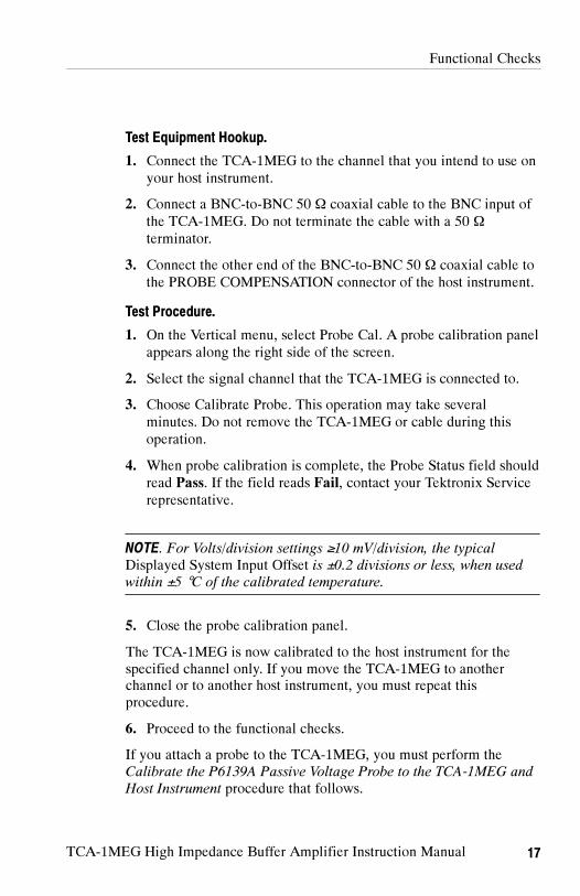
Test Equipment Hookup.
1. Connect the TCA-1MEG to the channel that you intend to use onyour host instrument.
2. Connect a BNC-to-BNC 50 Ω coaxial cable to the BNC input ofthe TCA-1MEG. Do not terminate the cable with a 50 Ω
terminator.
3. Connect the other end of the BNC-to-BNC 50 Ω coaxial cable tothe PROBE COMPENSATION connector of the host instrument.
Test Procedure.
1. On the Vertical menu, select Probe Cal. A probe calibration panelappears along the right side of the screen.
2. Select the signal channel that the TCA-1MEG is connected to.
3. Choose Calibrate Probe. This operation may take severalminutes. Do not remove the TCA-1MEG or cable during thisoperation.
4. When probe calibration is complete, the Probe Status field shouldread Pass. If the field reads Fail, contact your Tektronix Servicerepresentative.
NOTE. For Volts/division settings ≥10 mV/division, the typicalDisplayed System Input Offset is ±0.2 divisions or less, when usedwithin ±5 °C of the calibrated temperature.
5. Close the probe calibration panel.
The TCA-1MEG is now calibrated to the host instrument for thespecified channel only. If you move the TCA-1MEG to anotherchannel or to another host instrument, you must repeat thisprocedure.
6. Proceed to the functional checks.
If you attach a probe to the TCA-1MEG, you must perform theCalibrate the P6139A Passive Voltage Probe to the TCA-1MEG andHost Instrument procedure that follows.

Functional Checks
18 TCA-1MEG High Impedance Buffer Amplifier Instruction Manual
Calibrate the P6139A Passive Voltage Probe to theTCA-1MEG and Host Instrument
A P6139A probe and an instrument calibration connection (orsuitable equivalent) are required for this procedure.
NOTE. Variations in the characteristics of the TCA-1MEG and/orprobe require you to adjust the low-frequency compensation of theprobe that is connected to the TCA-1MEG. Consider this wheneveryou connect a different probe to a TCA-1MEG, or when you move aprobe from one TCA-1MEG to another.
If a 1 kHz calibrated square wave displayed at 1 ms/division showssignificant amplitude differences between the leading and trailingedges, perform the LF Probe Compensation procedure (see page 20)to optimize low-frequency compensation.
Test Equipment Hookup.
1. Connect the TCA-1MEG to a channel on your host instrument.
2. Connect the probe to the TEKPROBE input of the TCA-1MEG.
3. Using a nonterminated probe tip-to-BNC adapter, connect theprobe to the probe calibration signal on the front panel of the hostinstrument.
4. Check for proper LF compensation: If a 1 kHz calibrated squarewave displayed at 1 ms/division shows significant amplitudedifferences between the leading and trailing edges, perform theLF Probe Compensation procedure to optimize low-frequencycompensation. (Use Figure 8 on page 22 as a guideline for properLF compensation.)

Functional Checks
TCA-1MEG High Impedance Buffer Amplifier Instruction Manual 19
Test Procedure.
Do the following after a warm up period of at least 20 minutes:
1. On the Vertical menu, select Probe Cal. A probe calibration panelappears along the right side of the screen.
2. Select the signal channel that the TCA-1MEG and/or probe areconnected to.
3. Choose Calibrate Probe. This operation may take severalminutes. Do not remove the TCA-1MEG or probe during thisoperation.
4. When probe calibration is complete, the Probe Status field shouldread Pass. If the field reads Fail, contact your Tektronix Servicerepresentative.
NOTE. For Volts/division settings ≥10 mV/division, the typicalDisplayed System Input Offset is ±0.2 divisions or less, when usedwithin ±5 °C of the calibrated temperature.
5. Close the probe calibration panel.
The TCA-1MEG and probe are now calibrated to the host instrumentfor the specified channel only. If you move the TCA-1MEG andprobe to another channel or to another host instrument, you mustrepeat the TCA-1MEG and probe calibration procedures.

Functional Checks
20 TCA-1MEG High Impedance Buffer Amplifier Instruction Manual
LF Probe Compensation
Variations in the TCA-1MEG input characteristics may require youto adjust the low-frequency compensation of the probe that isconnected to the TCA-1MEG. Consider this whenever you connect adifferent probe to a TCA-1MEG, or when you move a probe fromone TCA-1MEG to another.
If a 1 kHz calibrated square wave displayed at 1 ms/division showssignificant differences between the leading and trailing edges,perform these steps to optimize low-frequency compensation:
1. Connect the TCA-1MEG to any channel on the host instrument.
2. Connect the probe to the TEKPROBE input of the TCA-1MEG.
3. Using a nonterminated probe tip adapter, connect the probe to theprobe calibration signal on the front panel of the oscilloscope.
NOTE. After connecting the TCA-1MEG to the host instrument, allowthem to warm up for at least twenty minutes before performing thefunctional checks.

Functional Checks
TCA-1MEG High Impedance Buffer Amplifier Instruction Manual 21
P6139A
TDS6000 Series Oscilloscope
TCA--1MEGP6139A probe tip
Probe tip adapter(non terminated)
Probe compensation output
Figure 7: Setup with the P6139A attached to the TCA-1MEG
4. Press AUTOSET or otherwise adjust your host instrument todisplay a meaningful waveform.
5. On the Vertical menu, select Vertical Setup, and then choose thetab of the channel that the TCA-1MEG is connected to.
a. Set coupling to DC. Set trigger level to 50%.
b. Set bandwidth to Full.
c. Set vertical scale to 100 mV/division.
d. Set offset to 1.6.
e. Adjust vertical position of the waveform to display oncenter screen.
f. Close the panel.
6. Set horizontal scale to 1.0 ms.

Functional Checks
22 TCA-1MEG High Impedance Buffer Amplifier Instruction Manual
7. On the Horiz/Acq menu, select Horizontal/Acquisition Setup, andthen choose the Acquisition tab.
a. Set acquisition mode to High Resolution.
b. Close the panel.
8. Adjust the trimmer in the probe (accessible through thecompensation box) until you see a square wave with a perfectlyflat top on the display. Refer to Figure 8, below.
CAUTION. To avoid damaging the trimmer, use the adjustment toolsupplied with your probe. Adjustment tools from some probe modelsmay not be compatible with your probe.
Undercompensated Overcompensated Properly compensated
Figure 8: Probe compensation waveforms

Functional Checks
TCA-1MEG High Impedance Buffer Amplifier Instruction Manual 23
Check Vertical Input Coupling
Verify the AC, DC, and GND coupling of the TCA-1MEG.
Test Equipment Hookup. Refer to the hookup shown in Figure 9.
TDS6000 TekConnect oscilloscope
BNC cable from TCA-1MEG input to PROBE
COMPENSATION output. Do not use a 50 Ω
terminator.
TCA--1MEG
Figure 9: Test equipment hookup for the Vertical Input Coupling andBandwidth Limit checks
Test Procedure. Do the following:
1. On the front panel of the host instrument, press the buttoncorresponding to the channel the TCA-1MEG is connected to.
2. Push the AUTOSET button to display a waveform on the screen.
3. If autoset does not set the host instrument to 500 mV/division,manually change vertical V/division to 500 mV.
4. Using the Vertical Position control knob, position the waveformto two divisons above center screen.
5. On the Vertical menu, select Vertical Setup, and then choose thetab of the channel that the TCA-1MEG is connected to.
6. Set coupling to GND.

Functional Checks
24 TCA-1MEG High Impedance Buffer Amplifier Instruction Manual
The resulting waveform should appear as shown in Figure 10,below.
Figure 10: Typical waveform at GND
7. Set Coupling to AC, and set trigger level to 50%.The resulting waveform should appear as shown in Figure 11 onpage 25.

Functional Checks
TCA-1MEG High Impedance Buffer Amplifier Instruction Manual 25
Figure 11: Typical waveform at AC Coupling
8. Set Coupling to DC, and set trigger level to 50%.The resulting waveform should appear as shown in Figure 12 onpage 26.

Functional Checks
26 TCA-1MEG High Impedance Buffer Amplifier Instruction Manual
Figure 12: Typical waveform at DC Coupling
9. Leave the Coupling set to DC.
10.Close the panel.

Functional Checks
TCA-1MEG High Impedance Buffer Amplifier Instruction Manual 27
Check Bandwidth Limit
Verify bandwidth limits at full, 100 MHz, and 20 MHz.
Test Equipment Hookup. Use the same hardware configuration as theVertical Input Coupling check. Refer to Figure 9 on page 23.
Test Procedure. Do the following:
1. On the front panel of the host instrument, select the channel thatthe TCA-1MEG is connected to.
2. Set the vertical scale to 200 mV/division.
3. Set the horizontal scale to 40 ns/division.
4. On the Vertical menu, select Vertical Setup, and then choose thetab of the channel that the TCA-1MEG is connected to.
a. Set coupling to AC.
b. Set bandwidth to Full (500 MHz).
5. Set to trigger at 50%.
6. Set the horizontal position of the leading edge to the left of centerscreen.
NOTE. When full bandwidth is set, overshoot and ringing on thesignal is normal and does not indicate problems with theTCA-1MEG.
The resulting waveform should appear as shown in Figure 13 onpage 28.

Functional Checks
28 TCA-1MEG High Impedance Buffer Amplifier Instruction Manual
Figure 13: Typical waveform at Full (500 MHz) bandwidth
7. Set bandwidth to 100 MHz.
NOTE. When 100 MHz bandwidth is set, the signal risetime increasesand overshoot and ringing decreases.
The resulting waveform should appear as shown in Figure 14 onpage 29.

Functional Checks
TCA-1MEG High Impedance Buffer Amplifier Instruction Manual 29
Figure 14: Typical waveform at 100 MHz bandwidth
8. Set bandwidth to 20 MHz.
NOTE. When the 20 MHz bandwidth limit is set, signal risetime isnear 15 ns.
The resulting waveform should appear as shown in Figure 15 onpage 30.

Functional Checks
30 TCA-1MEG High Impedance Buffer Amplifier Instruction Manual
Figure 15: Typical waveform at 20 MHz bandwidth
9. After completing the bandwidth limit checks, do the following:
a. Set bandwidth to Full.
b. Set coupling to DC.
c. Press AUTOSET.
d. Close the panel.

TCA-1MEG High Impedance Buffer Amplifier Instruction Manual 31
Specifications
These specifications apply to the TCA-1MEG High ImpedanceBuffer Amplifier when used with Tektronix TekConnect hostinstruments.
Specifications for the TCA-1MEG fall into three categories:warranted, typical, and nominal characteristics. PerformanceVerification procedures are provided in the Performance Verificationsection for specifications marked with the symbol in Table 3.
Specifications
CAUTION. To prevent damage to the TCA-1MEG, do not applyvoltages that are beyond the input voltage rating for the TCA-1MEGspecified in Table 3.
Table 3: Warranted electrical specifications
Characteristic Description
Bandwidth (TCA-1MEG only), at --3dB,100 mV/division with 50 Ω termination
≥500 MHz when used with a Tektronix hostinstrument that has ≥1.5 GHz bandwidth.100 MHz bandwidth limit ±25%20 MHz bandwidth limit ±25%
Attenuation Maximum sensitivity to 10 V/division in1--2--5 sequence on a Tektronix hostinstrument
Input Capacitance 10 pF ±2 pF
Input Resistance, DC Coupled 1 MΩ ±1% at DC1 MΩ ±10% at ⎢Vin⎢> 50 V
P6139A Probe tip Bandwidth withTCA-1MEG, at 100 mV/division
≥500 MHz with TCA-1MEG connected to aTektronix 50Ω host instrument that has≥1.5 GHz bandwidth.

Specifications
32 TCA-1MEG High Impedance Buffer Amplifier Instruction Manual
Table 3: Warranted electrical specifications (Cont.)
Characteristic Description
Input Voltage Rating1 (with TCA-1MEG or a1X probe)
150 V, CAT 1
1 RMS voltage limited to ≤150 V for arbitrary waveshapes including DC. Forpulse widths less than 50 s, 400 Vpk, <30% DF. RMS = Root Mean Square= rms = the square root of the average of the sum of the squares of theinstantaneous voltage in one cycle = (fx i)
2n
Table 4: Typical electrical characteristics
Characteristic Description
Linear dynamic range The lesser of ±5 divisions or the dynamicrange of the TekConnect host instrument.
Bandwidth (TCA-1MEG only) ≥500 MHz when used with a TekConnecthost instrument that has ≥1.5 GHz band-width100 MHz ±25%20 MHz ±25%
Linearity 0.2%
Full bandwidth small signal risetime(TCA-1MEG only)
800 ps calculated from 0.40 / measuredbandwidth
AC Coupling (LF 3 dB cutoff frequency) ≤10 Hz with TCA-1MEG≤1 Hz with P6139A probe attached
DC Offset Drift 600 V/°C or less at output of TCA-1MEG
Displayed system input offset ±0.2 divisions or less, when used within±5 °C of calibrated temperature forV/division settings ≥10 mV/division
Propagation Delay ≤2 ns

Specifications
TCA-1MEG High Impedance Buffer Amplifier Instruction Manual 33
Phase
(degrees)
Magnitude
(ohm
s)
Frequency
10
100
1 K
10 K
100 K
1 M
Ω
Ω
Ω
Ω
Ω
Ω
--10.0 °
--30.0 °
--40.0 °
--20.0 °
0 °
--60.0 °
--70.0 °
--80.0 °
--90.0 °
--100.0 °
--50.0 °
1Hz
10Hz
1KHz
10KHz
100KHz
1MHz
10MHz
100MHz
1GHz
100Hz
Input Impedance and Phase versus Frequency
Magnitude
Phase
Figure 16: Typical Input Impedance and Phase versus Frequency

Specifications
34 TCA-1MEG High Impedance Buffer Amplifier Instruction Manual
0.1
1
10
100
1000
VACRMS
Voltage Derating versus Frequency
Frequency
1KHz
10KHz
100KHz
1MHz
10MHz
100MHz
1GHz
100Hz
Figure 17: Voltage Derating versus Frequency

Specifications
TCA-1MEG High Impedance Buffer Amplifier Instruction Manual 35
31.5 mm[1.240 in]
108.08 mm[4.255 in]
72.9 mm[2.870 in] 28.58 mm
[1.125 in]
46.1 mm[1.815 in]
43.43 mm[1.710 in]
Figure 18: TCA-1MEG dimensions
Table 5: Physical characteristics
Characteristic Description
Unit weight (TCA-1MEG) 5.5 oz (155 g) net
Table 6: Environmental characteristics
Characteristic Description
Operating Temperature + 32 F to + 122 F (0 °C to + 50 °C)
Humidity ≤80% relative humidity through the entire operatingrange
Altitude Operating: 9,842 ft (3,000 m)Nonoperating: 50,000 ft (15,240 m)

Specifications
36 TCA-1MEG High Impedance Buffer Amplifier Instruction Manual
Table 7: Certifications and compliances
Category Standards or description
EMC Compliance Meets the intent of Directive 89/336/EEC for ElectromagneticCompatibility when it is used with the product(s) stated in thespecifications table. Refer to the EMC specification publishedfor the stated products. May not meet the intent of the directiveif used with other products.
FCC Compliance Emissions comply with FCC Code of Federal Regulations 47,Part 15, Subpart B, Class A Limits.
EC Declaration ofConformity -- LowV l
Compliance was demonstrated to the following specification aslisted in the Official Journal of the European Communities:y
VoltageLow Voltage Directive 73/23/EEC, amended by 93/68/EEC
EN 61010-1/A2:1995Safety requirements for electrical equipment formeasurement, control, and laboratory use.
U.S. NationallyRecognized TestingLaboratory Listing
UL3111-1Standard for electrical measuring and test equipment.
Canadian Certification CAN/CSA C22.2 No. 1010.1Safety requirements for electrical equipment formeasurement, control, and laboratory use.
Additional Compliance ISA S82.02.01:1999Safety standard for electrical and electronic test,measuring, controlling, and related equipment.
IEC61010-1/A2:1995Safety requirements for electrical equipment formeasurement, control, and laboratory use.

Specifications
TCA-1MEG High Impedance Buffer Amplifier Instruction Manual 37
Table 7: Certifications and compliances (cont.)
Category Standards or description
Installation (Overvoltage)Category Descriptions
Terminals on this product may have different installation(overvoltage) category designations. The installation categoriesare:
CAT IIIDistribution-level mains (usually permanently connected).Equipment at this level is typically in a fixed industriallocation.
CAT IILocal-level mains (wall sockets). Equipment at this levelincludes appliances, portable tools, and similar products.Equipment is usually cord-connected.
CAT ISecondary (signal level) or battery operated circuits ofelectronic equipment.

Specifications
38 TCA-1MEG High Impedance Buffer Amplifier Instruction Manual
Table 7: Certifications and compliances (cont.)
Category Standards or description
Pollution DegreeDescriptions
A measure of the contaminates that could occur in theenvironment around and within a product. Typically the internalenvironment inside a product is considered to be the same asthe external. Products should be used only in the environmentfor which they are rated.
Pollution Degree 1No pollution or only dry, nonconductive pollution occurs.Products in this category are generally encapsulated,hermetically sealed, or located in clean rooms.
Pollution Degree 2Normally only dry, nonconductive pollution occurs.Occasionally a temporary conductivity that is caused bycondensation must be expected. This location is a typicaloffice/home environment. Temporary condensation occursonly when the product is out of service.
Pollution Degree 3Conductive pollution, or dry, nonconductive pollution thatbecomes conductive due to condensation. These aresheltered locations where neither temperature nor humidityis controlled. The area is protected from direct sunshine,rain, or direct wind.
Pollution Degree 4Pollution that generates persistent conductivity throughconductive dust, rain, or snow. Typical outdoor locations.
Equipment Type Test and measuring
Safety Class Class 1 (as defined in IEC 61010-1, Annex H) -- groundedproduct
Pollution Degree Pollution Degree 2 (as defined in IEC 61010-1). Note: Rated forindoor use only.

The following servicing instructions are for use only byqualified personnel. To avoid injury, do not perform anyservicing other than that stated in the operating instructionsunless you are qualified to do so. Refer to all safetysummaries before performing any service.
WARNING


TCA-1MEG High Impedance Buffer Amplifier Instruction Manual 41
Performance Verification
Use the following procedure to verify that the TCA-1MEG HighImpedance Buffer Amplifier meets the warranted specificationmarked with a in Table 3 of the Specifications section.
Perform a probe calibration (a TCA-1MEG calibration) procedurebefore performing this test. Refer to page 16 of the FunctionalChecks section for the probe calibration procedure.
Verify this specification:
TCA-1MEG System Bandwidth
Before beginning this procedure, photocopy the test record onpage 45, and use it to record the performance test results.
The equipment in Table 8, or a suitable substitute, is required fortesting the TCA-1MEG.
Table 8: Equipment required for performance verification
DescriptionMinimumrequirements Examples
Oscilloscope TCA-1MEG in a Tektronix
TekConnect Oscilloscope
with a bandwidth ≥1.5GHz
TDS6000, TDS7000, or
CSA7000 TekConnect
instruments
50Ω coaxial cable Connects BNC input of the
TCA--IMEG to the PROBE
COMPENSATION connec-
tion on the front panel of the
host instrument.
Tektronix part number
012-0057-XX
Leveled sine wave
generator
50 KHz to 500 MHz ± 3%
amplitude accuracy
Wavetek 95001
50Ω feedthrough
termination
BNC connectors Tektronix part number
011-0049-XX
1 Wavetek 9500 Oscilloscope Calibrator with two 9510 OutputModules.

Performance Verification
42 TCA-1MEG High Impedance Buffer Amplifier Instruction Manual
Required Software
To ensure compatibility of your TekConnect host instrument with theTCA-1MEG, your host instrument (for example, TDS6000,TDS7000, or CSA7000 series) must have the firmware upgradeV2.1.0 or higher. Upgrade instructions are available on the includedCD ROM, or visit our Web site at www.tek.com and select theSoftware and Drivers link.
NOTE. The test procedure references commands available on a
TDS6604 Oscilloscope. These commands are similar to commands
that other TekConnect host instruments use. If needed, refer to the
user manual and online help supplied with your instrument.
TCA-1MEG System Bandwidth
This test verifies the system bandwidth.
Test Equipment Hookup. Connect the TCA-1MEG to a channel of thehost instrument. Use a 50 Ω coaxial cable and 50 Ω BNC feed-through termination to connect the output of the leveled sine wavegenerator to the input of the TCA-1MEG. Refer to Figure 19, below.
50Ωterminator
Output
Leveled sine-wavegenerator
TDS6000 Series Oscilloscope
TCA--1MEG50Ω coaxial cable
Figure 19: TCA-1MEG System Bandwidth equipment hookup

Performance Verification
TCA-1MEG High Impedance Buffer Amplifier Instruction Manual 43
System Bandwidth Test Procedure. Use these instructions for testingthe TCA-1MEG system bandwidth.
1. Set the signal generator to a reference frequency of 50 kHz,setting the initial output level to display a waveform.
2. Push AUTOSET to display a waveform on the host instrumentscreen.
3. On the Horiz/Acq menu, select Horizontal/Acquisition Setup, andthen select the Acquisition tab.
a. Set acquisition to Average.
b. Adjust the number of averages to 16.
c. Close the panel.
4. Use the Trigger area of the front panel to:
a. Set trigger source to the channel where the TCA-1MEG isconnected.
b. Set trigger coupling to DC.
c. Set trigger slope to Positive.
d. Set trigger mode to Auto.
5. On the Measure menu, select Measurement Setup, selectAmplitude, and then select Peak to Peak.
6. On the Vertical menu, select Vertical Setup, choose the tab for thechannel where the TCA-1MEG is connected, and then set verticalcoupling to DC.
7. Use the vertical scale knob to set the channel to 100 mV/division.
8. Perform steps 9 through 13 for each of these vertical bandwidthsettings of the host instrument:
a. Full
b. 100 MHz
c. 20 MHz
9. On the Vertical Setup panel, set the vertical bandwidth that youare testing (refer to step 8, above).

Performance Verification
44 TCA-1MEG High Impedance Buffer Amplifier Instruction Manual
10. Set the horizontal scale to 10 s/division.
11. On the leveled sine wave generator, do the following:
a. Set the output frequency to 50 kHz.
b. Adjust the output amplitude until the peak-to-peakmeasurement displaying on the oscilloscope screen isbetween 599 mV and 601 mV.
12.On the leveled sine wave generator, set the output frequencyaccording to the bandwidth limit you are testing:
a. For bandwidth limit set to Full, set the sine wavegenerator to 500 MHz. Set the horizontal scale of theoscilloscope to 5 ns/division. Record the measured value.
b. For bandwidth limit set to 100 MHz, Set the sine wave generator to 75 MHz. Set thehorizontal scale of the oscilloscope to 10 ns/division.Record the measured value. Set the sine wave generator to 125 MHz. Record themeasured value.
c. For bandwidth limit set to 20 MHz, Set the sine wave generator to 15 MHz. Set thehorizontal scale of the oscilloscope to 20 ns/division.Record the measured value. Set the sine wave generator to 25 MHz. Record themeasured value.
13.Verify that the peak-to-peak measurement of the oscilloscopemeets the specification listed on the TCA-1MEG Test Record --System bandwidth verification.
NOTE. If the results of these tests do not meet the specifications listed
on the TCA-1MEG test record, contact your Tektronix Service
representative.

Performance Verification
TCA-1MEG High Impedance Buffer Amplifier Instruction Manual 45
Use this test record to record the test results of the TCA-1MEGSystem Bandwidth tests.
TCA-1MEG Test Record
Instrument Serial Number: Certificate Number:
Temperature: RH %:
Date of Calibration: Technician:
Input Amplitude (600 mV):
System bandwidth verification
Input voltage Specification1 Measured as
Full(500 MHz) ≥ 425 mVp--p
100 MHz limitmin. 75 MHz ≥ 425 mVp--p
max. 125 MHz ≤ 425 mVp--p
20 MHz limitmin. 15 MHz ≥ 425 mVp--p
max. 25 MHz ≤ 425 mVp--p
1 The 425 mV specification limit is based on a 600 mV input level.- 3 dB voltage level = input voltage x 70.7%,calculated as 425 mV = 600 mV x 0.707

Performance Verification
46 TCA-1MEG High Impedance Buffer Amplifier Instruction Manual

TCA-1MEG High Impedance Buffer Amplifier Instruction Manual 47
Replaceable Parts
This section contains a list of replaceable parts for the TCA-1MEGHigh Impedance Buffer Amplifier. Use this list to identify and orderreplacement parts.
Parts Ordering Information
Replacement parts are available from or through your localTektronix, Inc. service center or representative.
Changes to Tektronix instruments are sometimes made to accommo-date improved components as they become available and to give youthe benefit of the latest circuit improvements. Therefore, whenordering parts, it is important to include the following information inyour order:
Part number
Instrument type or model number
Instrument serial number
Instrument modification number, if applicable
If a part you order has been replaced with a different or improvedpart, your local Tektronix service center or representative willcontact you concerning any change in the part number.

Replaceable Parts
48 TCA-1MEG High Impedance Buffer Amplifier Instruction Manual
Using the Replaceable Parts List
The tabular information in the Replaceable Parts List is arranged forquick retrieval. Understanding the structure and features of the listwill help you find the information you need for ordering replacementparts.
Item Names
In the Replaceable Parts List, an Item Name is separated from thedescription by a colon (:). Because of space limitations, an ItemName may sometimes appear as incomplete. For further Item Nameidentification, U.S. Federal Cataloging Handbook H6-1 can be usedwhere possible.
Indentation System
This parts list is indented to show the relationship between items.The following example is of the indentation system used in theDescription column:
1 2 3 4 5 Name & DescriptionAssembly and/or ComponentAttaching parts for Assembly and/or Component
(END ATTACHING PARTS)Detail Part of Assembly and/or ComponentAttaching parts for Detail Part
(END ATTACHING PARTS)Parts of Detail PartAttaching parts for Parts of Detail Part
(END ATTACHING PARTS)
Attaching parts always appear at the same indentation as the item itmounts, while the detail parts are indented to the right. Indenteditems are part of, and included with, the next higher indentation.Attaching parts must be purchased separately, unless otherwisespecified.
Abbreviations
Abbreviations conform to American National Standards Institute(ANSI) standard Y1.1

Replaceable Parts
TCA-1MEG High Impedance Buffer Amplifier Instruction Manual 49
Manufacturers
crossindex
Mfr.
code
Manufacturer
Address
City,state,zipcode
80009
TEKTRONIX
INC
14150SW
KARLBRAUNDR
POBOX500
BEAVERTON,OR97077--0001

Replaceable Parts
TCA-1MEG High Impedance Buffer Amplifier Instruction Manual50
1
23
TCA--1MEG
4
5
Figure
20:TCA-1MEGreplaceableparts
Fig.&
index
no.
Tektronix
partno.
Serialno.
Effective
Dscont
Qty
12345nam
e&description
Mfr.
code
Mfr.partno.
20--1
TCA-1MEG
1TCA-1MEGAMPLIFIER,HIGHIMPEDANCEBUFFER,
1MEGOHM/10PF,TEKPROBEBNC-TO-TEKCONNECT,
with
P6139A
80009
TCA-1MEG
STA
NDARDACCESSORIES
--2P6139A
1P6139A!0XPASSIVEPROBE;STANDARDACCESSORIES
80009
P6139A
--3071-1010-XX
1MANUAL,TECH:INSTRUCTION,TCA-1MEG
80009
071-1010-XX

Replaceable Parts
TCA-1MEG High Impedance Buffer Amplifier Instruction Manual 51
Fig.&
index
no.
Mfr.partno.
Mfr.
code
12345nam
e&description
Qty
Serialno.
Effective
Dscont
Tektronix
partno.
--4063-3541-XX
1SOFTWAREPKG;PRODUCTSOFTWARE,CD,V2.1.0;
TDS6000SERIES
80009
063-3541-XX
--5063-3461-XX
1SOFTWAREPKG;PRODUCTSOFTWARE,CD,V2.1.0;
TDS7000SERIES
80009
063-3461-XX

Replaceable Parts
TCA-1MEG High Impedance Buffer Amplifier Instruction Manual52
1
Figure
21:TCA-1MEGoptionalaccessories
Fig.&
index
no.
Tektronix
partno.
Serialno.
Effective
Dscont
Qty
12345nam
e&description
Mfr.
code
Mfr.partno.
OPTIONALACCESSORIES
21--1
063-3376-XX
1TDS7000SERIESAPPLICATIONSSOFTWAREPKG,
PRODUCTCD
80009
063-3376-XX


