TC8 Conformance Testing of Automotive Ethernet Networks...Ethernet Link TAPping Automotive Ethernet...
30
V1.0 | 2019-05-01 Vector Testing Symposium 7.5.2019 | Heiner Hild TC8 Conformance Testing of Automotive Ethernet Networks
Transcript of TC8 Conformance Testing of Automotive Ethernet Networks...Ethernet Link TAPping Automotive Ethernet...

V1.0 | 2019-05-01
Vector Testing Symposium 7.5.2019 | Heiner Hild
TC8 Conformance Testing of Automotive Ethernet Networks

2 © 2019. Vector Informatik GmbH. All rights reserved. Any distribution or copying is subject to prior written approval by Vector. V1.0 | 2019-05-01
Communication Networks in Domain Centric E/E Architectures
Overview + Motivation

3 © 2019. Vector Informatik GmbH. All rights reserved. Any distribution or copying is subject to prior written approval by Vector. V1.0 | 2019-05-01
Communication Networks in Domain Centric E/E Architectures
Overview + Motivation
DiagnosisTester
PowertrainDomain Controller
BodyDomain Controller
ADASDomain Controller
InfotainmentDomain Controller
ChassisDomain Controller
Engine
Transmission
Battery Man.
ESC
Steering
Airbag
Doors
Seats
Lights
Radar
Camera
Lidar
HMI
HUD
Radio
HS-C
AN
Fle
xRay
/ H
S-C
AN
CAN
/ L
IN
Eth
ern
et
Eth
ern
et
/ M
OST
Ethernet
EthernetCar2X
Ethernet Ethernet
Ethernet
Ethernet
Central Gateway

4 © 2019. Vector Informatik GmbH. All rights reserved. Any distribution or copying is subject to prior written approval by Vector. V1.0 | 2019-05-01
Access to Automotive Bus Systems
Overview + Motivation
DiagnosisTester Car2XCentral Gateway
USBPowertrainDomain Controller
BodyDomain Controller
ChassisDomain Controller
Engine
Transmission
Battery Man.
ESC
Steering
Airbag
Doors
Seats
Lights
HS-C
AN
Fle
xRay
LIN
How about Ethernet ?

5 © 2019. Vector Informatik GmbH. All rights reserved. Any distribution or copying is subject to prior written approval by Vector. V1.0 | 2019-05-01
Overview + Motivation
u Automotive Ethernet Testing
OPEN Alliance SIG
Examplary Ethernet Test System
Summary
Outlook VT System
Agenda
6 © 2019. Vector Informatik GmbH. All rights reserved. Any distribution or copying is subject to prior written approval by Vector. V1.0 | 2019-05-01
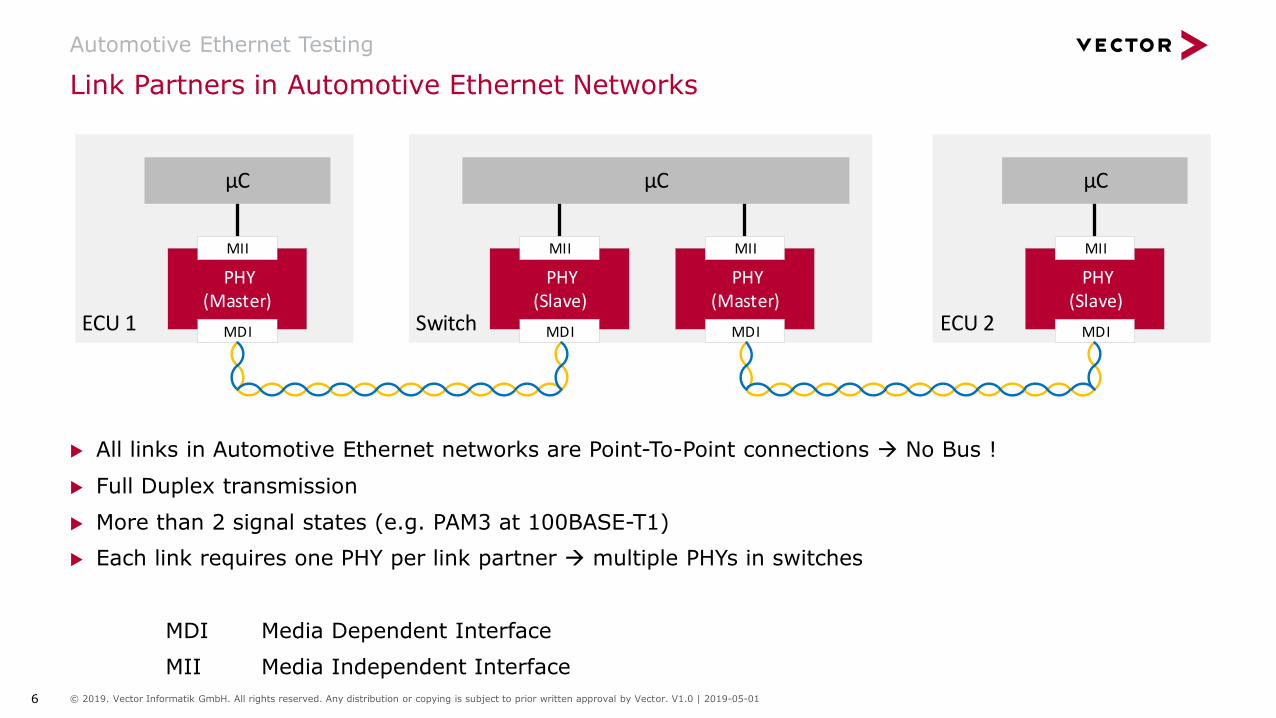
u All links in Automotive Ethernet networks are Point-To-Point connections → No Bus !
u Full Duplex transmission
u More than 2 signal states (e.g. PAM3 at 100BASE-T1)
u Each link requires one PHY per link partner → multiple PHYs in switches
MDI Media Dependent Interface
MII Media Independent Interface
Link Partners in Automotive Ethernet Networks
Automotive Ethernet Testing
SwitchECU 1
PHY(Master)
MDI
µC
MII
PHY(Slave)
MDI
MII
PHY(Master)
MDI
MII
µC
ECU 2
PHY(Slave)
MDI
µC
MII

7 © 2019. Vector Informatik GmbH. All rights reserved. Any distribution or copying is subject to prior written approval by Vector. V1.0 | 2019-05-01
Access to Automotive Ethernet Networks
Automotive Ethernet Testing
DiagnosisTester
PowertrainDomain Controller
BodyDomain Controller
InfotainmentDomain Controller
Radar
Camera
HMI
HUD
Radio
Car2X
Lidar
ETH / PCI Express
Test Access Points (TAPs)
for each link of interest
Central Gateway
ChassisDomain Controller
ADASDomain Controller
8 © 2019. Vector Informatik GmbH. All rights reserved. Any distribution or copying is subject to prior written approval by Vector. V1.0 | 2019-05-01
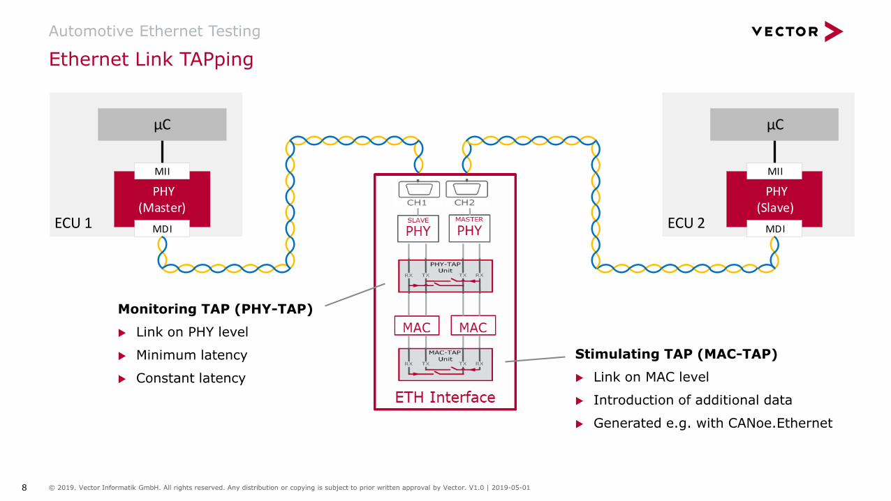
Ethernet Link TAPping
Automotive Ethernet Testing
ECU 1
PHY(Master)
MDI
µC
MII
ECU 2
PHY(Slave)
MDI
µC
MII
Monitoring TAP (PHY-TAP)
u Link on PHY level
u Minimum latency
u Constant latency
Stimulating TAP (MAC-TAP)
u Link on MAC level
u Introduction of additional data
u Generated e.g. with CANoe.Ethernet

9 © 2019. Vector Informatik GmbH. All rights reserved. Any distribution or copying is subject to prior written approval by Vector. V1.0 | 2019-05-01
Overview + Motivation
Automotive Ethernet Testing
u OPEN Alliance SIG
Examplary Ethernet Test System
Summary
Outlook VT System
Agenda

10 © 2019. Vector Informatik GmbH. All rights reserved. Any distribution or copying is subject to prior written approval by Vector. V1.0 | 2019-05-01
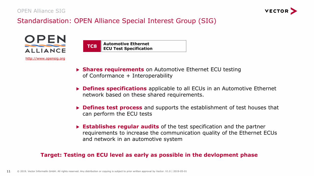
Standardisation: OPEN Alliance Special Interest Group (SIG)
OPEN Alliance SIG
Interoperability & Compliance Testsfor 100BASE-T1 PHYs
100BASE-T1 Ethernet Channel & Components
1000BASE-T1 CMC Requirements
Tools
Gap Identification
Common xMII Interface Definition
1000BASE-RH Gigabit Ethernet over Plastic-Optical-Fiber (GEPOF)
Automotive Ethernet ECU Test Specification
1000BASE-T1 Ethernet Channel & Components
Automotive Ethernet Sleep/Wake-Up
Ethernet switch requirements and qualification
Test specs for the compliance testing of future IEEE 1000BASE-T1… devices
TC1
TC2
TC3
TC4
TC5
TC6
TC7
TC8
TC9
TC10
TC11
TC12
http://www.opensig.org
11 © 2019. Vector Informatik GmbH. All rights reserved. Any distribution or copying is subject to prior written approval by Vector. V1.0 | 2019-05-01
Standardisation: OPEN Alliance Special Interest Group (SIG)
OPEN Alliance SIG
Automotive Ethernet ECU Test Specification
TC8
http://www.opensig.org
u Shares requirements on Automotive Ethernet ECU testingof Conformance + Interoperability
u Defines specifications applicable to all ECUs in an Automotive Ethernet network based on these shared requirements.
u Defines test process and supports the establishment of test houses that can perform the ECU tests
u Establishes regular audits of the test specification and the partner requirements to increase the communication quality of the Ethernet ECUs and network in an automotive system
Target: Testing on ECU level as early as possible in the devlopment phase

12 © 2019. Vector Informatik GmbH. All rights reserved. Any distribution or copying is subject to prior written approval by Vector. V1.0 | 2019-05-01
AutomotiveEthernet
TCP/IP ProtocolFamily
Automotive Protocols
Automotive ISO/OSI Layer Model – Application Areas and TC8 Test Scopes
OPEN Alliance SIG
TC8 ECU TestTest Scopes
7
Physical
Data Link
Network
Transport
Application
ISO/OSI Layer
SOME/IP DoIP XCP
TCP/UDP
IPv4/IPv6
AVB / TSN
IEEE Ethernet MAC + VLAN
Ethernet PHY(IEEE 100BASE-T1, IEEE100BASE-Tx, IEEE1000BASE-T)
6
5
4
3
2
1
Command / Control communication
Diagnostics andFlash Update
Measurement andCalibration
Audio/VideoTime Sync

13 © 2019. Vector Informatik GmbH. All rights reserved. Any distribution or copying is subject to prior written approval by Vector. V1.0 | 2019-05-01
AutomotiveEthernet
TCP/IP ProtocolFamily
Automotive Protocols
Application
Transport
Network
Data Link
Physical
Test Groups in the TC8 Tests
OPEN Alliance SIG
TC8 ECU TestTest Scopes ISO/OSI Layer

14 © 2019. Vector Informatik GmbH. All rights reserved. Any distribution or copying is subject to prior written approval by Vector. V1.0 | 2019-05-01
Overview + Motivation
Automotive Ethernet Testing
OPEN Alliance SIG
u Examplary Ethernet Test System
Summary
Outlook VT System
Agenda

15 © 2019. Vector Informatik GmbH. All rights reserved. Any distribution or copying is subject to prior written approval by Vector. V1.0 | 2019-05-01
Target
u One Test System forall ISO/OSI layers
Test System CANoe + vTESTstudio + VT System
Examplary Ethernet Test System

16 © 2019. Vector Informatik GmbH. All rights reserved. Any distribution or copying is subject to prior written approval by Vector. V1.0 | 2019-05-01
u Implementation in vTESTstudio
u Test configuration
u One global parameter file(general settings for the DUT, e.g. IP address)
u One specific parameter file for each Test Group
TC8 Test Implementation
Examplary Ethernet Test System
17 © 2019. Vector Informatik GmbH. All rights reserved. Any distribution or copying is subject to prior written approval by Vector. V1.0 | 2019-05-01
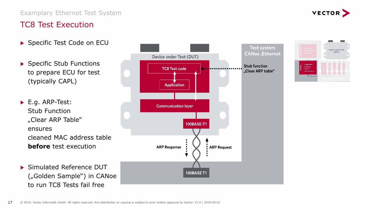
u Specific Test Code on ECU
u Specific Stub Functions
to prepare ECU for test
(typically CAPL)
u E.g. ARP-Test:
Stub Function
„Clear ARP Table“
ensures
cleaned MAC address table
before test execution
u Simulated Reference DUT
(„Golden Sample“) in CANoe
to run TC8 Tests fail free
TC8 Test Execution
Examplary Ethernet Test System

18 © 2019. Vector Informatik GmbH. All rights reserved. Any distribution or copying is subject to prior written approval by Vector. V1.0 | 2019-05-01
TC8 Test Spec Example OABR_CABLE_01: Cable diagnostics for near and far end open
Examplary Ethernet Test System
Source: OPEN Alliance TC8 Automotive Ethernet ECU Test Specification v2.0
Test Steps
1. The DUT cable diagnostic feature is triggered. The DUT cable diagnostics has to be executed within terror
2. The test system creates a cable error for a defined time terror
3. After the wait time t the test system reads out all identified cable errors QC from the DUT
4. Repeat step 1 to 3 for all error combinations (alternately MDI+ and/or MDI- are open)
Test Goal
Ensure that the DUT’scable diagnostic reliablydetects an open of one orboth of the bus lines
Test Setup forFar Open Test

19 © 2019. Vector Informatik GmbH. All rights reserved. Any distribution or copying is subject to prior written approval by Vector. V1.0 | 2019-05-01
u 6 Automotive Ethernet channels on separate piggy board
u 2x 100BASE-TX/1000BASE-T channels on main board
u High precision time stamps for Ethernet frames
u Synchronization with multiple bus interfaces
u Hardware sync (1 µs accuracy)
u Ethernet Monitoring between two nodes
u Media conversion between 100BASE-TX/1000BASE-T and Automotive Ethernet channels
u Flexible, hardware based monitor filter
u Multiple, configurable Test Access Points (TAPs)
u Monitoring TAP: test mode with constant and very low latency with direct PHY connection
u Stimulation TAP: channel connection an MAC level. This allows transmission of additional packets
u Configurable layer2-switch operation mode
u Further Ethernet Interfaces available
VT6306 Ethernet Interface
Examplary Ethernet Test System

20 © 2019. Vector Informatik GmbH. All rights reserved. Any distribution or copying is subject to prior written approval by Vector. V1.0 | 2019-05-01
VN5610A VN5640VT6306 +
piggyVN5620 VN5430
User Ports
100/1000BASE-T1 2x 100BASE-T1 12x 6x 4x 6x
10BASE-T/100BASE-Tx/1000BASE-T
2x 4x 2x -- --
CAN / CAN FD 2x 2x -- 2x --
I/O Channels 1x digital1x analog5x digital
Arbitrarynumberfrom VT System
1x digital --
Fault Injection on physical layer no no yes no no
Host Connection USB2.0 USB3.0 PCI ExpressUSB3.1 Ethernet
Ethernet
Powering USB / External External via VT SystemUSB /
ExternalExternal
Automotive Ethernet Interfaces
Examplary Ethernet Test System
21 © 2019. Vector Informatik GmbH. All rights reserved. Any distribution or copying is subject to prior written approval by Vector. V1.0 | 2019-05-01
u Automotive Ethernet
u Occurrence in modern EE architectures
u Difference to classical Bus Protocols
u Link Access with TAPs
u OPEN Alliance SIG
u Structure
u TC8 – Tests with Test Scopes for all ISO/OSI layers
u Exemplary TC8 Test System
u Test implementation in vTESTstudio: Parameter files to adapt to specific ECU
u Test execution with CANoe: Stub Functions acting on specific test code + Golden Sample
u DUT interfacing with VT System / various ETH interfaces
TC8 Testing - Summary
Summary

22 © 2019. Vector Informatik GmbH. All rights reserved. Any distribution or copying is subject to prior written approval by Vector. V1.0 | 2019-05-01
Overview + Motivation
Automotive Ethernet Testing
OPEN Alliance SIG
Examplary Ethernet Test System
Summary
u Outlook VT System
Agenda

23 © 2019. Vector Informatik GmbH. All rights reserved. Any distribution or copying is subject to prior written approval by Vector. V1.0 | 2019-05-01
Characteristics▪ Basis modules▪ No direct SUT connection
Gaps▪ PC Power▪ High Speed▪ Network
channels▪ Image
Processing▪ …
Characteristics▪ Function Blocks▪ Fault Injection▪ Break Out▪ Status LED
Characteristics▪ Simple IO▪ Many channels▪ Test System or ECU
VT System Concept
Outlook VT System
Charatecristics▪ Function Blocks▪ Fault Injection▪ Break Out▪ Sim / Ori switch▪ Status LED
ECU / IO
Network
System
Infrastructure
Gaps▪ 48V grids▪ High Current▪ High Speed▪ …
Existing▪ VT1004A▪ VT2004A▪ VT2516A▪ VT7001A
Test
Syste
m
Gaps▪ Gbit Ethernet▪ Further serial
busses▪ …
Existing▪ VT6104A▪ VT6204▪ VT2710
Existing▪ VT6000▪ VT8006A▪ VT8012A▪ Housings▪ Power
Supplies
Gaps▪ Switch Matrix▪ …
Existing▪ VT2816▪ VT2820▪ VT2848

24 © 2019. Vector Informatik GmbH. All rights reserved. Any distribution or copying is subject to prior written approval by Vector. V1.0 | 2019-05-01
Motivation
u Switching of higher currents
u PWM switching / bouncing contact simulation
u Many switching cycles (endurance tests)
Main Features
u Size of switch matrix: 8 columns x 4 rows
u Current carrying capability per switched path: max. 16A
u Coupling of channels for higher currents possible
u Switched voltage up to 60V
u Modular Design → aggregation to bigger switch matrices possible
u Solid State Relay (SSR) technology → wear-free switching for endurance tests
u Fast switching with min. 10 kHz possible e.g. for bouncing contact simulation
VT2832 - Switch Matrix Module
Outlook VT System

25 © 2019. Vector Informatik GmbH. All rights reserved. Any distribution or copying is subject to prior written approval by Vector. V1.0 | 2019-05-01
Use Cases
u Current switching + measurement
u PWM switching / bouncing contact simulation
u Endurance Tests
Configuration
u Each switched path is given a unique colour
u Connected paths are given thesame color
u Each column can be switchedindependently with PWM orbitstream
u PWM and bitstreamconfiguration is identical toother VT System modules
VT2832 - Switch Matrix Module
Outlook VT System

26 © 2019. Vector Informatik GmbH. All rights reserved. Any distribution or copying is subject to prior written approval by Vector. V1.0 | 2019-05-01
Use Cases
u Highly synchronized output of analog and/or digital signals
u Fast data exchange between User FPGA modules
Realisation
u Ring architecture between User FPGA processor boards
u Simultaneous flashing of multiple VT System User FPGA module is now possiblein VT System FPGA Manager
Inter Board Communication (IBC) between User FPGA Modules
Outlook VT System
Enabler Check Box
Receiver Matrix
Sender Dropdown
Multi Module Project Setup

27 © 2019. Vector Informatik GmbH. All rights reserved. Any distribution or copying is subject to prior written approval by Vector. V1.0 | 2019-05-01
48V – Vehicle Power Support
Motivation
u Hybrid 48V / 12V electrical systems are becoming more important
u Testing of 48V EE systems requires measurement / stimulation > 54V
Main Features
u 60V capability
u Solid State Relay (SRR) based solution
u Solutions for
u ECU outputs: VT1104 (60V-Variant of VT1004A
u ECU Power Supply: VT7101 (60V-Variant of VT7001A)
u Configuration concept is maintained
u Internal Power Supply of VT7101 up to 60V / 0.5A
Outlook VT System
VT1104
VT7101
DC measurement l l
DC output l
Arbitrary curves l
Fault injection / switching l l
28 © 2019. Vector Informatik GmbH. All rights reserved. Any distribution or copying is subject to prior written approval by Vector. V1.0 | 2019-05-01
VT2808 Current Measurement Module
Outlook VT System
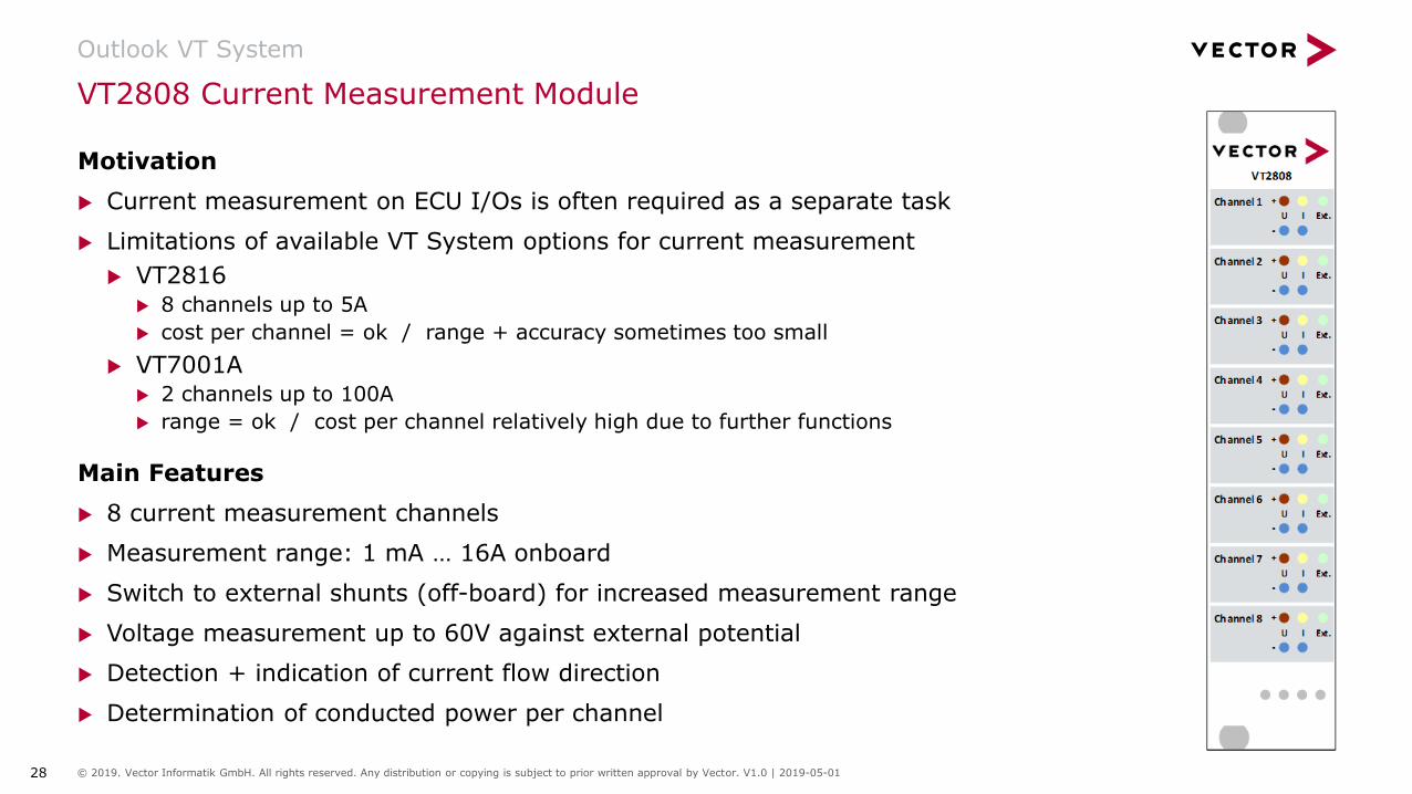
Motivation
u Current measurement on ECU I/Os is often required as a separate task
u Limitations of available VT System options for current measurement
u VT2816u 8 channels up to 5A
u cost per channel = ok / range + accuracy sometimes too small
u VT7001Au 2 channels up to 100A
u range = ok / cost per channel relatively high due to further functions
Main Features
u 8 current measurement channels
u Measurement range: 1 mA … 16A onboard
u Switch to external shunts (off-board) for increased measurement range
u Voltage measurement up to 60V against external potential
u Detection + indication of current flow direction
u Determination of conducted power per channel
29 © 2019. Vector Informatik GmbH. All rights reserved. Any distribution or copying is subject to prior written approval by Vector. V1.0 | 2019-05-01
VT60xx Next Gen RT Module (Concept)
Outlook VT System
Motivation
u Number of bus channels with VT6051A is limited to 16
u Some applications e.g. realtime simulations require higher computing power
u More Ethernet connectors e.g. for LXI measurement devices or PC coupling
u Connector system for host uplink PCIe (x1) over cable is discontinued
Main Requirements
u Processor minimum intel Core i7 Gen.7 / QuadCore
u Minimum 32 bus channels can be operated via VT System Network Interface
u Minimum 2 additional Gbit/s general purpose Ethernet ports (min. 4x overall)
u Minimum 2 USB3.0 ports
u Space consumption: 2 slots in VT System Housing

30 © 2019. Vector Informatik GmbH. All rights reserved. Any distribution or copying is subject to prior written approval by Vector. V1.0 | 2019-05-01
Author:Hild, HeinerVector Germany
For more information about Vectorand our products please visit
www.vector.com
Thanks for your attendance