
TC35i AT Commands
439
mobile TC35i TC35i Terminal Siemens Cellular Engine Version: 02.07 DocId: TC35i_ATC_V02.07
-
Upload
ali-khaledi -
Category
Documents
-
view
271 -
download
3
Transcript of TC35i AT Commands

TC35iTC35i TerminalSiemens Cellular Engine Version: 02.07DocId: TC35i_ATC_V02.07

TC35i AT Command Set
TC35i_ATC_V02.07 Page 2 of 439 1/30/04Confidential / Released
s
mobile
General NotesProduct is deemed accepted by recipient and is provided without interface to recipient’s products. The documen-tation and/or product are provided for testing, evaluation, integration and information purposes. The documen-tation and/or product are provided on an “as is” basis only and may contain deficiencies or inadequacies. Thedocumentation and/or product are provided without warranty of any kind, express or implied. To the maximumextent permitted by applicable law, Siemens further disclaims all warranties, including without limitation any im-plied warranties of merchantability, completeness, fitness for a particular purpose and non-infringement of third-party rights. The entire risk arising out of the use or performance of the product and documentation remains withrecipient. This product is not intended for use in life support appliances, devices or systems where a malfunctionof the product can reasonably be expected to result in personal injury. Applications incorporating the describedproduct must be designed to be in accordance with the technical specifications provided in these guidelines. Fail-ure to comply with any of the required procedures can result in malfunctions or serious discrepancies in results.Furthermore, all safety instructions regarding the use of mobile technical systems, including GSM products,which also apply to cellular phones must be followed. Siemens or its suppliers shall, regardless of any legal the-ory upon which the claim is based, not be liable for any consequential, incidental, direct, indirect, punitive or otherdamages whatsoever (including, without limitation, damages for loss of business profits, business interruption,loss of business information or data, or other pecuniary loss) arising out the use of or inability to use the docu-mentation and/or product, even if Siemens has been advised of the possibility of such damages. The foregoinglimitations of liability shall not apply in case of mandatory liability, e.g. under the German Product Liability Act, incase of intent, gross negligence, injury of life, body or health, or breach of a condition which goes to the root ofthe contract. However, claims for damages arising from a breach of a condition, which goes to the root of thecontract, shall be limited to the foreseeable damage, which is intrinsic to the contract, unless caused by intent orgross negligence or based on liability for injury of life, body or health. The above provision does not imply achange on the burden of proof to the detriment of the recipient. Subject to change without notice at any time. Theinterpretation of this general note shall be governed and construed according to German law without referenceto any other substantive law.
CopyrightTransmittal, reproduction, dissemination and/or editing of this document as well as utilization of its contents andcommunication thereof to others without express authorization are prohibited. Offenders will be held liable forpayment of damages. All rights created by patent grant or registration of a utility model or design patent are re-served.
Copyright © Siemens AG January 30, 2004
Document Name: TC35i AT Command SetVersion: 02.07
Date: January 30, 2004
DocId: TC35i_ATC_V02.07
Status Confidential / Released

TC35i AT Command SetContents s
mobile
1. Introduction............................................................................................................................................ 121.1 Scope of the document ................................................................................................................. 12
1.2 Related documents ....................................................................................................................... 131.3 Document conventions.................................................................................................................. 14
1.3.1 Quick reference table ....................................................................................................... 141.3.2 Superscript notation for parameters and values............................................................... 15
1.4 AT command syntax...................................................................................................................... 16
1.4.1 Using parameters ............................................................................................................. 161.4.2 Combining AT commands on the same command line.................................................... 17
1.5 Supported character sets .............................................................................................................. 18
1.5.1 GSM alphabet tables and UCS2 character values........................................................... 201.5.2 UCS2 and GSM data coding and conversion for SMS text mode.................................... 221.5.2.1 Implementing output of SIM data to the TE (direction ME to TE)..................................... 221.5.2.2 Implementing input of Terminal data to SIM (direction TE to ME) .................................... 23
1.6 Flow Control .................................................................................................................................. 251.6.1 Software flow control (XON/OFF flow control) ................................................................. 251.6.2 Hardware flow control (RTS/CTS flow control)................................................................. 25
1.7 Unsolicited Result Code Presentation........................................................................................... 26
1.7.1 Communication between Customer Application and TC35i ............................................. 261.8 Errors and Messages .................................................................................................................... 27
2. Configuration Commands..................................................................................................................... 282.1 AT&F Set all current parameters to manufacturer defaults ......................................................... 28
2.2 AT&V Display current configuration ............................................................................................ 29
2.2.1 AT&V responses .............................................................................................................. 292.3 AT&W Stores current configuration to user defined profile ......................................................... 32
2.4 ATQ Set result code presentation mode ..................................................................................... 33
2.5 ATV Set result code format mode ............................................................................................... 342.5.1 Verbose and numeric result codes................................................................................... 34
2.6 ATX Set CONNECT result code format and call monitoring ....................................................... 36
2.7 AT\V Set CONNECT result code format ..................................................................................... 372.8 ATZ Set all current parameters to user defined profile................................................................ 38
2.9 AT+CFUN Set phone functionality .............................................................................................. 39
2.9.1 Wake up the ME from SLEEP mode ................................................................................ 422.10 AT^SMSO Switch off mobile station............................................................................................ 44
2.11 AT+GCAP Request complete TA capabilities list........................................................................ 45
2.12 AT+CMEE Report mobile equipment error ................................................................................. 462.12.1 Summary of CME ERRORS related to GSM 07.07 ......................................................... 472.12.2 Summary of CMS ERRORS related to GSM 07.05 ......................................................... 48
Contents
TC35i_ATC_V02.07 Page 3 of 439 1/30/04Confidential / Released

TC35i AT Command SetContents s
mobile
2.13 AT+CSCS Select TE character set ............................................................................................. 51
2.14 AT^SCFG Extended Configuration Settings ............................................................................... 532.15 AT^SM20 Set M20 compatibility mode ....................................................................................... 59
3. Status Control Commands ................................................................................................................... 613.1 AT+CMER Mobile Equipment Event Reporting .......................................................................... 61
3.2 AT+CIND Indicator control .......................................................................................................... 64
3.3 AT^SIND Extended Indicator Control .......................................................................................... 683.4 AT+CEER Extended error report ................................................................................................ 71
3.4.1 Cause Location ID for the extended error report.............................................................. 733.4.2 GSM release cause for L3 Radio Resource (RR) ............................................................ 743.4.3 SIEMENS release cause for L3 Radio Resource (RR) .................................................... 743.4.4 GSM release cause for Mobility Management (MM) ........................................................ 753.4.5 SIEMENS release cause for L3 Mobility Management (MM) ........................................... 763.4.6 GSM release cause for L3 Call Control (CC) ................................................................... 763.4.7 SIEMENS release cause for L3 Call Control (CC) ........................................................... 783.4.8 SIEMENS release cause for L3 Advice of Charge (AOC)................................................ 783.4.9 GSM Release cause for Supplementary Service Call ...................................................... 783.4.10 SIEMENS release cause for Call-related Supplementary Services (CRSS).................... 80
3.5 ATS18 Extended call release report............................................................................................ 82
3.6 AT+CPAS Mobile equipment activity status................................................................................ 843.7 AT+WS46 Select wireless network ............................................................................................. 85
4. Serial Interface Control Commands..................................................................................................... 864.1 AT\Q Flowcontrol......................................................................................................................... 86
4.2 AT&C Set circuit Data Carrier Detect (DCD) function mode ....................................................... 87
4.3 AT&D Set circuit Data Terminal Ready (DTR) function mode..................................................... 884.4 AT%D Automatic Dial on DTR Line Activation ............................................................................ 89
4.5 AT&S Set circuit Data Set Ready (DSR) function mode ............................................................. 92
4.6 ATE Enable command echo........................................................................................................ 934.7 AT+ICF Serial Interface Character Framing................................................................................ 94
4.8 AT+IFC Set Flow Control separately for data directions ............................................................. 96
4.9 AT+ILRR Set TE-TA local rate reporting..................................................................................... 984.10 AT+IPR Set fixed local rate ....................................................................................................... 100
4.10.1 Autobauding ................................................................................................................... 102
4.11 AT+CMUX Enter multiplex mode .............................................................................................. 1034.11.1 Restrictions on Multiplex mode ...................................................................................... 104
4.12 AT^STPB Transmit Parity Bit (for 7E1 and 7O1 only) ............................................................... 107
5. Security Commands............................................................................................................................ 1095.1 AT+CPIN Enter PIN .................................................................................................................. 109
5.1.1 What to do if PIN or password authentication fails?....................................................... 1115.2 AT+CPIN2 Enter PIN2 .............................................................................................................. 113
5.3 AT^SPIC Display PIN counter ................................................................................................... 116
TC35i_ATC_V02.07 Page 4 of 439 1/30/04Confidential / Released

TC35i AT Command SetContents s
mobile
5.4 AT+CLCK Facility lock .............................................................................................................. 119
5.5 AT^SLCK Facility lock ............................................................................................................... 1255.6 AT+CPWD Change Password .................................................................................................. 126
5.7 AT^SPWD Change Password................................................................................................... 130
6. Identification Commands.................................................................................................................... 1316.1 ATI Display product identification information ........................................................................... 131
6.2 AT+CGMI Request manufacturer identification......................................................................... 1326.3 AT+GMI Request manufacturer identification ........................................................................... 133
6.4 AT+CGMM Request model identification .................................................................................. 134
6.5 AT+GMM Request TA model identification ............................................................................... 1356.6 AT+CGMR Request revision identification of software status................................................... 136
6.7 AT+GMR Request TA revision identification of software status................................................ 137
6.8 AT+CGSN Request product serial number identification (IMEI) identical to GSN .................... 1386.9 AT+GSN Request TA serial number identification(IMEI) .......................................................... 139
6.10 AT+CIMI Request international mobile subscriber identity ....................................................... 140
7. Call related Commands....................................................................................................................... 1417.1 ATA Answer a call ..................................................................................................................... 141
7.2 ATD Mobile originated call to dial a number.............................................................................. 143
7.3 ATD><mem><n> Originate call to phone number in memory................................................... 1467.4 ATD><n> Originate call to phone number selected from active memory.................................. 148
7.5 ATD><str> Originate call to phone number in memory with corresponding field ...................... 150
7.6 ATDI Mobile originated call to dialable ISDN number <n> ........................................................ 1527.7 ATDL Redial last telephone number used................................................................................. 153
7.8 ATH Disconnect existing connection......................................................................................... 154
7.9 AT+CHUP Hang up call ............................................................................................................ 1557.10 AT^SHUP Hang up call(s) indicating a specific GSM04.08 release cause ............................... 156
7.11 ATS0 Set number of rings before automatically answering the call .......................................... 158
7.12 ATS6 Set pause before blind dialing ......................................................................................... 1597.13 ATS7 Set number of seconds to wait for connection completion .............................................. 160
7.14 ATS8 Set number of seconds to wait for comma dialing modifier............................................. 161
7.15 ATS10 Set disconnect delay after indicating the absence of data carrier ................................. 1627.16 ATP Select pulse dialing ........................................................................................................... 163
7.17 ATO Switch from command mode to data mode ...................................................................... 164
7.18 +++ Switch from data mode to command mode ....................................................................... 1657.19 ATT Select tone dialing ............................................................................................................. 166
7.20 AT+CBST Select bearer service type ....................................................................................... 167
7.21 AT+CRLP Select radio link protocol param. for orig. non-transparent data call........................ 1697.22 AT+CLCC List current calls of ME ............................................................................................ 171
7.23 AT+CR Service reporting control .............................................................................................. 174
7.24 AT+CRC Set Cellular Result Codes for incoming call indication .............................................. 176
TC35i_ATC_V02.07 Page 5 of 439 1/30/04Confidential / Released

TC35i AT Command SetContents s
mobile
7.25 AT+CSNS Single Numbering Scheme...................................................................................... 178
7.26 AT^SCNI List Call Number Information..................................................................................... 1807.27 AT^SLCD Display Last Call Duration ........................................................................................ 182
7.28 AT^STCD Display Total Call Duration....................................................................................... 183
8. Network Service Commands .............................................................................................................. 1848.1 AT+COPN Read operator names ............................................................................................. 184
8.2 AT+COPS Operator selection ................................................................................................... 1858.3 AT+CREG Network registration ................................................................................................ 187
8.4 AT+CSQ Signal quality ............................................................................................................. 190
8.5 AT^SMONC Cell Monitoring...................................................................................................... 1928.6 AT^SMOND Selective Cell Monitoring ...................................................................................... 194
8.7 AT^MONI Monitor idle mode and dedicated mode ................................................................... 199
8.7.1 AT^MONI responses ...................................................................................................... 2008.7.2 Service states................................................................................................................. 2018.7.3 Notes .............................................................................................................................. 201
8.8 AT^MONP Monitor neighbour cells ........................................................................................... 2038.8.1 AT^MONP responses..................................................................................................... 204
8.9 AT^SALS Alternate Line Service............................................................................................... 205
8.10 AT^SHOM Display Homezone .................................................................................................. 207
8.11 AT^SPLM Read the PLMN list .................................................................................................. 2088.12 AT^SPLR Read entry from the preferred operators list............................................................. 209
8.13 AT^SPLW Write an entry to the preferred operators list ........................................................... 211
9. Supplementary Service Commands .................................................................................................. 2129.1 AT+CACM Accumulated call meter (ACM) reset or query ........................................................ 212
9.2 AT^SACM Advice of charge and query of ACM and ACMmax ................................................. 2149.3 AT+CAMM Accumulated call meter maximum (ACMmax) set or query.................................... 216
9.4 AT+CAOC Advice of Charge information.................................................................................. 218
9.5 AT+CCUG Closed User Group ................................................................................................. 2209.6 AT+CCFC Call forwarding number and conditions control ....................................................... 222
9.7 AT+CCWA Call Waiting ............................................................................................................ 226
9.8 AT+CHLD Call Hold and Multiparty........................................................................................... 2309.9 AT+CLIP Calling line identification presentation ....................................................................... 233
9.10 AT+CLIR Calling line identification restriction ........................................................................... 235
9.11 AT+CPUC Price per unit and currency table............................................................................. 2379.12 AT+CSSN Supplementary service notifications ........................................................................ 239
9.13 AT+CUSD Supplementary service notifications........................................................................ 241
10. FAX Commands................................................................................................................................... 24310.1 FAX parameters .......................................................................................................................... 243
10.2 AT+FBADLIN Bad Line Treshold .............................................................................................. 24610.3 AT+FBADMUL Error Threshold Multiplier ................................................................................. 247
TC35i_ATC_V02.07 Page 6 of 439 1/30/04Confidential / Released

TC35i AT Command SetContents s
mobile
10.4 AT+FBOR Query data bit order................................................................................................. 248
10.5 AT+FCIG Query or set the Local polling id ............................................................................... 24910.6 AT+FCLASS Fax: Select, read or test service class................................................................. 250
10.7 AT+FCQ Copy Quality Checking .............................................................................................. 252
10.8 AT+FCR Capability to receive................................................................................................... 25310.9 AT+FDCC Query or set capabilities .......................................................................................... 254
10.10 AT+FDFFC Data Compression Format Conversion ................................................................. 255
10.11 AT+FDIS Query or set session parameters .............................................................................. 25610.12 AT+FDR Begin or continue phase C data reception ................................................................. 257
10.13 AT+FDT Data Transmission...................................................................................................... 258
10.14 AT+FET End a page or document ............................................................................................ 25910.15 AT+FK Kill operation, orderly FAX abort ................................................................................... 260
10.16 AT+FLID Query or set the Local Id setting capabilities ............................................................. 261
10.17 AT+FMDL identify Product Model ............................................................................................ 26210.18 AT+FMFR Request Manufacturer Identification........................................................................ 263
10.19 AT+FOPT Set bit order independently ...................................................................................... 264
10.20 AT+FPHCTO DTE Phase C Response Timeout....................................................................... 26510.21 AT+FREV Identify Product Revision ......................................................................................... 266
10.22 AT+FRH Receive Data Using HDLC Framing .......................................................................... 267
10.23 AT+FRM Receive Data ............................................................................................................. 268
10.24 AT+FRS Receive Silence.......................................................................................................... 26910.25 AT+FTH Transmit Data Using HDLC Framing.......................................................................... 270
10.26 AT+FTM Transmit Data............................................................................................................. 271
10.27 AT+FTS Stop Transmission and Wait ....................................................................................... 27210.28 AT+FVRFC Vertical resolution format conversion .................................................................... 273
11. Short Message Service (SMS) Commands........................................................................................ 27411.1 SMS parameters ......................................................................................................................... 274
11.2 AT+CMGC Send an SMS command......................................................................................... 279
11.3 AT+CMGD Delete SMS message............................................................................................. 28011.4 AT+CMGF Select SMS message format .................................................................................. 281
11.5 AT+CMGL List SMS messages from preferred store................................................................ 282
11.6 AT+CMGR Read SMS messages............................................................................................. 28411.7 AT+CMGS Send SMS message ............................................................................................... 286
11.8 AT+CMGW Write SMS messages to memory .......................................................................... 288
11.9 AT+CMSS Send SMS messages from storage ........................................................................ 29011.10 AT+CNMA New SMS message acknowledge to ME/TE, only phase 2+ .................................. 291
11.11 AT+CNMI New SMS message indications................................................................................ 293
11.12 AT+CPMS Preferred SMS message storage............................................................................ 29711.13 AT+CSCA SMS service centre address.................................................................................... 300
11.14 AT+CSCB Select Cell Broadcast Message Indication .............................................................. 301
TC35i_ATC_V02.07 Page 7 of 439 1/30/04Confidential / Released

TC35i AT Command SetContents s
mobile
11.15 AT+CSDH Show SMS text mode parameters........................................................................... 303
11.16 AT+CSMP Set SMS text mode parameters .............................................................................. 30411.17 AT+CSMS Select Message Service.......................................................................................... 306
11.18 AT^SCML List Concatenated SMS messages from preferred store ......................................... 308
11.19 AT^SCMR Read concatenated SMS messages ....................................................................... 31011.20 AT^SCMS Send concatenated SMS messages ....................................................................... 312
11.21 AT^SCMW Write concatenated SMS messages to memory .................................................... 313
11.22 AT^SLMS List SMS Memory Storage ....................................................................................... 31411.23 AT^SMGL List SMS messages from preferred store without setting status to REC READ ...... 316
11.24 AT^SMGO Set or query SMS overflow presentation mode or query SMS overflow ................. 318
11.25 AT^SMGR Read SMS message without setting status to REC READ ..................................... 32011.26 AT^SSCONF SMS Configuration ............................................................................................. 321
11.27 AT^SSDA Set SMS Display Availability .................................................................................... 323
11.28 AT^SSMSS Set Short Message Storage Sequence ................................................................. 325
12. SIM related Commands....................................................................................................................... 32612.1 AT+CRSM Restricted SIM Access............................................................................................ 32612.2 AT^SCKS Query SIM and Chip Card Holder Status ................................................................. 329
12.3 AT^SSET Indicate SIM data ready............................................................................................ 331
12.4 AT^SCID Display SIM card identification number ..................................................................... 333
12.5 AT+CXXCID Display card ID..................................................................................................... 334
13. SIM Application Toolkit (SAT) Commands........................................................................................ 33513.1 AT^SSTA SAT Interface Activation ........................................................................................... 33513.2 ^SSTN SAT Notification ............................................................................................................ 337
13.3 AT^SSTGI SAT Get Information ............................................................................................... 339
13.4 AT^SSTR SAT Response ......................................................................................................... 341
14. Phonebook Commands....................................................................................................................... 34314.1 Sort Order for Phonebooks ......................................................................................................... 34314.2 AT+CPBR Read from Phonebook............................................................................................. 344
14.3 AT+CPBS Select phonebook memory storage ......................................................................... 347
14.4 AT+CPBW Write into Phonebook ............................................................................................. 34914.5 AT^SPBC Search the first entry in the sorted telephone book.................................................. 352
14.6 AT^SPBD Purge phonebook memory storage.......................................................................... 354
14.7 AT^SPBG Read current Phonebook entries ............................................................................. 35614.8 AT^SPBS Step through the selected phonebook alphabetically ............................................... 359
14.9 AT^SDLD Delete the 'last number redial' memory .................................................................... 363
15. Audio Commands................................................................................................................................ 36415.1 Audio programming model .......................................................................................................... 364
15.2 ATL Set monitor speaker loudness ........................................................................................... 36515.3 ATM Set monitor speaker mode................................................................................................ 366
TC35i_ATC_V02.07 Page 8 of 439 1/30/04Confidential / Released

TC35i AT Command SetContents s
mobile
15.4 AT+CLVL Loudspeaker volume level........................................................................................ 367
15.5 AT+CMUT Mute control ............................................................................................................ 36915.6 AT+VTD Tone duration ............................................................................................................. 370
15.7 AT+VTS DTMF and tone generation......................................................................................... 371
15.8 AT^SAIC Audio Interface Configuration .................................................................................... 37315.9 AT^SNFA Set or query of microphone attenuation .................................................................. 375
15.10 AT^SNFD Set audio parameters to manufacturer default values ............................................. 377
15.11 AT^SNFI Set microphone path parameters .............................................................................. 37815.12 AT^SNFM Mute microphone ..................................................................................................... 380
15.13 AT^SNFO Set audio output (= loudspeaker path) parameter ................................................... 382
15.14 AT^SNFPT Set progress tones ................................................................................................. 38415.15 AT^SNFS Select audio hardware set........................................................................................ 385
15.16 AT^SNFV Set loudspeaker volume........................................................................................... 389
15.17 AT^SNFW Write audio setting in non-volatile store .................................................................. 39115.18 AT^SRTC Ring tone configuration ............................................................................................ 392
16. Hardware related Commands............................................................................................................. 39516.1 AT+CALA Set alarm time ......................................................................................................... 395
16.1.1 Summary of AT commands available in Alarm mode .................................................... 398
16.2 AT+CCLK Real Time Clock....................................................................................................... 399
16.3 AT^SBC Battery charging / discharging and charge control ..................................................... 40016.3.1 Summary of AT commands available in Charge-only and Alarm mode......................... 402
16.4 AT^SBV Battery/Supply Voltage ............................................................................................... 403
16.5 AT^SCTM Set critical operating temperature presentation mode or query temperature........... 40416.6 AT^SSYNC Configure SYNC Pin.............................................................................................. 407
16.6.1 ME status indicated by status LED patterns................................................................... 408
17. Miscellaneous Commands.................................................................................................................. 41017.1 A/ Repeat previous command line ............................................................................................ 410
17.2 ATS3 Write command line termination character...................................................................... 41117.3 ATS4 Set response formatting character .................................................................................. 412
17.4 ATS5 Write command line editing character ............................................................................. 413
18. Appendix .............................................................................................................................................. 41418.1 Restricted access to SIM data after SIM PIN authentication....................................................... 414
18.2 List of *# Codes ........................................................................................................................... 41518.3 Available AT Commands and Dependency on SIM PIN ............................................................. 419
18.4 AT Command Settings storable with AT&W................................................................................ 426
18.5 Factory Default Settings Restorable with AT&F.......................................................................... 42918.6 Summary of Unsolicited Result Codes (URC)............................................................................. 432
18.7 Alphabetical List of AT Commands ............................................................................................. 434
TC35i_ATC_V02.07 Page 9 of 439 1/30/04Confidential / Released

TC35i AT Command SetList of Tables s
mobile
TC35i_ATC_V02.07 Page 10 of 439 1/30/04Confidential / Released
Table 1.1: Product specific use of AT commands ...................................................................................... 12Table 1.2: Symbols used to indicate the correlations with other commands ............................................... 15Table 1.3: Symbols used to mark different types of default values of parameters ..................................... 15Table 2.1: Current configuration on ASC0 / MUX channel 1 (example) ...................................................... 30Table 2.2: Current configuration on MUX channels 2 and 3 (example) ...................................................... 31Table 4.1: Availability of AT Commands on Virtual Channels .................................................................. 104Table 4.2: Summary of AT commands with Different Behavior in Multiplex Mode ................................... 105Table 16.1: Modes of the LED and indicated ME functions......................................................................... 408Table 18.1: List of *# Codes ........................................................................................................................ 415Table 18.2: Abbreviations of Codes and Parameters Used in Table "List of *# Codes".............................. 416Table 18.3: Available AT Commands and Dependency on SIM PIN........................................................... 419Table 18.4: Settings Stored to User Profile on ASC0 / MUX Channel 1...................................................... 426Table 18.5: Settings Stored to User Profile on MUX Channels 2 and 3 ...................................................... 427Table 18.6: Factory Default Settings Restorable with AT&F ....................................................................... 429Table 18.7: Summary of Unsolicited Result Codes (URC) .......................................................................... 432Table 18.8: Alphabetical List of AT Commands........................................................................................... 434
List of Tables
TC35i AT Command SetList of Figures s
mobile
TC35i_ATC_V02.07 Page 11 of 439 1/30/04Confidential / Released
Figure 1.1: Main character table of GSM 03.38 alphabet ............................................................................. 20Figure 1.2: Extension character table of GSM 03.38 alphabet ..................................................................... 21Figure 15.1: Audio programming model........................................................................................................ 364
List of Figures

TC35i AT Command Set1. Introduction s
mobile
1. Introduction
1.1 Scope of the document
This document presents the AT Command Set for the Siemens Cellular Engines TC35i Version 02.07 TC35i Terminal Version 02.07.
Before using the Cellular Engine or upgrading to a new firmware version please read the latest product informa-tion provided in the Release Notes [1].
More information is available at the Siemens Website: http://www.siemens.com/wm.
If features differ between TC35i and TC35i Terminal this is noted in the section that refers to the AT command. At present the following features are concerned:
Table 1.1: Product specific use of AT commands
AT command Module version Terminal version
AT+ILRR Maximum bit rate: 230400 bps Maximum bit rate: 115200 bps
AT+IPR Maximum bit rate: 230400 bps Maximum bit rate: 115200 bps
AT+CALA Alarm mode and reminder message fully applicable
Does not support Alarm mode. Please ignore any information relating to the subject.The reminder message can be used as described.
AT^SAIC All parameters usable as described. Additional recommendations for using audio modes 2, 3 and 6 with TC35i Ter-minal.
AT^SSYNC SYNC pin may be assigned different functions: <mode> 0 , 1 or 2.
SYNC pin supports only <mode>=1 or 2. (LED status)
AT^SBC All functions fully applicable Command not applicable
TC35i_ATC_V02.07 Page 12 of 439 1/30/04Confidential / Released

TC35i AT Command Set1.2 Related documents s
mobile
1.2 Related documents
[1] Release Notes: TC35i, Version 02.07[2] TC35i Hardware Interface Description, Version 02.07[3] Remote-SAT User's Guide[4] Multiplexer User's Guide[5] Application Note 16: Updating TC35i Firmware[6] TC35i Terminal Hardware Interface Description[7] TC35i Terminal User's Guide[8] Application Note 02: Audio Interface Design[9] Multiplex Driver Developer's Guide for Windows 2000 and Windows XP
[10] Multiplex Driver Installation Guide for Windows 2000 and Windows XP[11] ISO/IEC10646: "Universal Multiple-Octet Coded Character Set (UCS)"; UCS2, 16 bit coding [12] ITU-T Recommendation V.24: List of definitions for interchange circuits between data terminal equipment
(DTE) and data circuit-terminating equipment (DCE) [13] ITU-T Recommendation V.25ter: Serial asynchronous automatic dialling and control [14] 3GPP TS 23.038 (GSM 03.38): Alphabets and language specific information [15] 3GPP TS 27.005 (GSM 07.05): Use of Data Terminal Equipment - Data Circuit terminating Equipment (DTE
- DCE) interface for Short Message Service (SMS) and Cell Broadcast Service (CBS) [16] 3GPP TS 27.007 (GSM 07.07): AT command set for User Equipment (UE) [17] 3GPP TS 27.060 (GSM 07.60): Mobile Station (MS) supporting Packet Switched Services [18] 3GPP TS 51.011 (GSM 11.11): Specification of the Subscriber Identity Module - Mobile Equipment (SIM -
ME) interface [19] 3GPP TS 11.14 (GSM 11.14): Specification of the SIM Application Toolkit for the Subscriber Identity Module
- Mobile Equipment (SIM - ME) interface
TC35i_ATC_V02.07 Page 13 of 439 1/30/04Confidential / Released

TC35i AT Command Set1.3 Document conventions s
mobile
1.3 Document conventions
Throughout the document, the GSM engines are referred to as ME (Mobile Equipment), MS (Mobile Station), TA(Terminal Adapter), DCE (Data Communication Equipment) or facsimile DCE (FAX modem, FAX board). Whenthe Siemens product names are required to distinguish the two models, TC35i is short for the engine type andTC35iT for the terminal. To control your GSM engine you can simply send AT Commands via its serial interface. The controlling deviceat the other end of the serial line is referred to as TE (Terminal Equipment), DTE (Data Terminal Equipment) orplainly 'the application' (probably running on an embedded system). All abbreviations and acronyms used throughout this document are based on the GSM specifications. For defi-nitions please refer to TR 100 350 V7.0.0 (1999-08), (GSM 01.04, version 7.0.0 release 1998).
1.3.1 Quick reference tableEach AT command description includes a table similar to the example shown below. The table is intended as aquick reference to indicate the following functions:
Example:
PIN: Is the AT command PIN protected? � Yes � No � Usage is dependent on conditions specified for the command, or not all command types are PIN
protected (for example write command PIN protected, read command not). Note: The table provided in the Chapter Available AT Commands and Dependency on SIM PIN
uses the same symbols.
ASC0: Is the AT command supported on the physical serial interface ASC0? � Yes � No Note: In the case of TC35i only "Yes" applies.
MUXn: Is the AT command usable on the Multiplexer channels MUX1, MUX2, MUX3? � Yes
� No � AT command is usable, but under the restrictions specified in the chapter related to the com-
mand. Note: The columns MUX1, MUX2 and MUX3 are relevant only when the GSM engine operates in Mul-
tiplexer mode, that is, when the physical serial interface is partitioned into 3 virtual channels by using the Multiplexer protocol. Usage is the same on ASC0 and MUX1.
PIN ASC0 MUX1 MUX2 MUX3
� � � � �
TC35i_ATC_V02.07 Page 14 of 439 1/30/04Confidential / Released

TC35i AT Command Set1.3 Document conventions s
mobile
1.3.2 Superscript notation for parameters and values
Table 1.2: Symbols used to indicate the correlations with other commands
Table 1.3: Symbols used to mark different types of default values of parameters
Parameter option Meaning
<param>(&W) Parameter value will be stored with AT&W
<param>(&V) Parameter value will be displayed with AT&V
<param>(ˆSNFW) Parameter value will be stored with AT^SNFW
<param>(+CSCS) Parameter value has to be (is) coded according to current setting of <chset> (see AT+CSCS for details)
Value option Meaning
[x] Default value: if the parameter is omitted, the value 'x' will be assumed
x(&F) Factory default value, will be restored to 'x' with AT&F
x(P) Powerup default value of a parameter which is not stored at power down
x(D) Delivery default value of a parameter which cannot be restored automatically
TC35i_ATC_V02.07 Page 15 of 439 1/30/04Confidential / Released

TC35i AT Command Set1.4 AT command syntax s
mobile
1.4 AT command syntax
The "AT" or "at" prefix must be set at the beginning of each command line. To terminate a command line enter<CR>. Commands are usually followed by a response that includes "<CR><LF><response><CR><LF>". Throughout thisdocument, only the responses are presented, <CR><LF> are omitted intentionally.
Types of AT commands and responses:
1.4.1 Using parameters• Optional parameters are enclosed in square brackets. If optional parameters are omitted, the current settings
are used until you change them.• Optional parameters or subparameters can be omitted unless they are followed by other parameters. If you
want to omit a parameter in the middle of a string it must be replaced by a comma. See also example 1.• A parameter value enclosed in square brackets represents the value that will be used if an optional parameter
is omitted. See also example 2.• When the parameter is a character string, e.g. <text> or <number>, the string must be enclosed in quotation
marks, e.g. "Charlie Brown" or "+49030xxxx". Symbols within quotation marks will be recognized as strings. • All spaces will be ignored when using strings without quotaton marks.• It is possible to omit the leading zeros of strings which represent numbers.• If an optional parameter of a V.25ter command is omitted, its value is assumed to be 0.
AT command type Syntax Function
Test command AT+CXXX=? The mobile equipment returns the list of parameters and value ranges set with the corresponding Write command or by internal processes.
Read command AT+CXXX? This command returns the currently set value of the parameter or parameters.
Write command AT+CXXX=<...> This command sets user-definable parameter values.
Exec(ution) command AT+CXXX The execution command reads non-variable parameters deter-mined by internal processes in the GSM engine.
TC35i_ATC_V02.07 Page 16 of 439 1/30/04Confidential / Released

TC35i AT Command Set1.4 AT command syntax s
mobile
Example 1: Omitting parameters in the middle of a string
Example 2: Using default parameter values for optional parameters
1.4.2 Combining AT commands on the same command lineYou may enter several AT commands on the same line. This eliminates the need to type the "AT" or "at" prefixbefore each command. Instead, it is only needed once at the beginning of the command line. Use a semicolonas command delimiter. The command line buffer accepts a maximum of 391 characters. If this number is exceeded none of the com-mands will be executed and TA returns ERROR. The table below lists the AT commands you cannot enter together with other commands on the same line. Oth-erwise, the responses may not be in the expected order.
Note: When concatenating AT commands please keep in mind that the sequence of processing may be differentfrom the sequential order of command input. Therefore, if the consecutive order of the issued commands is yourconcern, avoid concatenating commands on the same line.
AT+CCUG? Query current setting+CCUG: 1,10,1
OK
AT+CCUG=,9 Set only the middle parameterOK
AT+CCUG? Query new setting+CCUG: 1,9,1
OK
AT+CFUN=5,0 Activate CYCLIC SLEEP mode, don't reset MEOK
AT+CFUN? Query ME mode+CFUN: 5
OK
AT+CFUN= Set ME back to normal (default parameters: 1,0)OK
+CFUN: 1
OK
AT command type Comment
V.25ter commands with FAX commands (Prefix AT+F)
GSM 7.07 commands with Siemens commands, Prefix AT^S)
GSM 7.05 commands (SMS) To be used standalone
Commands starting with AT& To be used standalone
AT+IPR To be used standalone
TC35i_ATC_V02.07 Page 17 of 439 1/30/04Confidential / Released

TC35i AT Command Set1.5 Supported character sets s
mobile
1.5 Supported character sets
The ME supports two character sets: GSM 03.38 (7 bit, also referred to as GSM alphabet or SMS alphabet) andUCS2 (16 bit, refer to ISO/IEC 10646). See AT+CSCS for information about selecting the character set. Charactertables can be found below.
Explanation of terms • IRA
IRA means that one byte is displayed as two characters in hexadecimal format. for example, the byte 0x36(decimal 54) is displayed as "36" (two chars).
• Escape sequencesThe escape sequence used within a text coded in the GSM default alphabet (0x1B) must be correctly inter-preted by the TE, both for character input and output. To the module, an escape sequence appears like anyother byte received or sent.
• TETE is the terminal equipment that uses the GSM default alphabet as its character set. MS Hyperterminal(often used with the module) is an ANSI / ASCII terminal that does not support the GSM default alphabet.
• Data Coding SchemeThe Data Coding Scheme (dcs) is part of a short message and is saved on the SIM. When writing a shortmessage to the SIM in textmode, the dcs stored with AT+CSMP is used.
• TE Character SetThe currently used TE character set is selected with AT+CSCS.
The behavior when encountering characters, that are not valid characters of the supported alphabets, is unde-fined. Due to the constraints described below it is recommended to prefer the USC2 alphabet in any external applica-tion. If the GSM alphabet is selected all characters sent over the serial line are in the range from 0 ... 127. CAUTION:GSM alphabet is not ASCII alphabet!
Several problems resulting from the use of the GSM alphabet: • "@" character with GSM alphabet value 0 is not printable by an ASCII terminal program (e.g. Microsoft©
Hyperterminal®).• "@" character with GSM alphabet value of binary 0 will terminate any C string! This is because the 0 is defined
as C string end tag. Therefore, the GSM Null character may cause problems on application level when usinga 'C'-function as "strlen()". This can be avoided if it is represented by an escape sequence as shown in thetable below. By the way, this may be the reason why even network providers often replace "@"with "@=*" in their SIMapplication.
• Other characters of the GSM alphabet are misinterpreted by an ASCII terminal program. For example, GSM"ö" (as in "Börse") is assumed to be "|" in ASCII, thus resulting in "B|rse". This is because both alphabets meandifferent characters with values hex. 7C or 00 and so on.
• In addition, decimal 17 and 19 which are used as XON/XOFF control characters when software flow controlis activated, are interpreted as normal characters in the GSM alphabet.
When you write characters differently coded in ASCII and GSM (e.g. Ä, Ö, Ü), you need to enter escapesequences. Such a character is translated into the corresponding GSM character value and, when output later,the GSM character value can be presented. Any ASCII terminal then will show wrong responses. Examples for character definitions depending on alphabet
TC35i_ATC_V02.07 Page 18 of 439 1/30/04Confidential / Released

TC35i AT Command Set1.5 Supported character sets s
mobile
CAUTION: Often, the editors of terminal programs do not recognize escape sequences. In this case, an escapesequence will be handled as normal characters. The most common workaround to this problem is to write a scriptwhich includes a decimal code instead of an escape sequence. This way you can write, for example, short mes-sages which may contain differently coded characters.
GSM 03.38character
GSM characterhex. value
CorrespondingASCII character
ASCIIEsc sequence
Hex Escsequence
Ö 5C \ \5C 5C 35 43
" 22 " \22 5C 32 32
ò 08 BSP \08 5C 30 38
@ 00 NULL \00 5C 30 30
TC35i_ATC_V02.07 Page 19 of 439 1/30/04Confidential / Released

TC35i AT Command Set1.5 Supported character sets s
mobile
1.5.1 GSM alphabet tables and UCS2 character valuesThis section provides tables for the GSM 03.38 alphabet supported by the ME. Below any GSM character findthe corresponding two byte character value of the UCS2 alphabet.
1) This code is an escape to the following extension of the 7 bit default alphabet table.2) This code is not a printable character and therefore not defined for the UCS2 alphabet. It shall be treated as the accom-
panying control character.
Figure 1.1: Main character table of GSM 03.38 alphabet
TC35i_ATC_V02.07 Page 20 of 439 1/30/04Confidential / Released

TC35i AT Command Set1.5 Supported character sets s
mobile
1) This code value is reserved for the extension to another extension table. On receipt of this code, a receiving entity shalldisplay a space until another extension table is defined.
2) This code represents the EURO currency symbol. The code value is the one used for the character 'e'. Therefore a receiv-ing entity which is incapable of displaying the EURO currency symbol will display the character 'e' instead.
3) This code is defined as a Page Break character and may be used for example in compressed CBS messages. Any mobilewhich does not understand the 7 bit default alphabet table extension mechanism will treat this character as Line Feed.
Figure 1.2: Extension character table of GSM 03.38 alphabet
TC35i_ATC_V02.07 Page 21 of 439 1/30/04Confidential / Released

TC35i AT Command Set1.5 Supported character sets s
mobile
In the event that an MS receives a code where a symbol is not represented in figure Extension character tableof GSM 03.38 alphabet the MS shall display the character shown in the main default 7 bit alphabet table (seefigure Main character table of GSM 03.38 alphabet).
1.5.2 UCS2 and GSM data coding and conversion for SMS text modeThis chapter provides basic information on how to handle input and output character conversion for SMS textmode and Remote-SAT if internal (ME) and external (TE) character representation differ, i.e. if the Data CodingScheme and the TE character use different coding.
1.5.2.1 Implementing output of SIM data to the TE (direction ME to TE)
Case 1Every byte will be sent as GSM character (or ASCII with Hyperterminal).Example: 0x41,0x21 � "AB" (because of conversion from 7-bit to 8-bit)
Case 2Every byte will be sent as IRA. No conversion.Example: 0x41,0x42 � "4142"
Case 3Every byte will be sent as IRA. No conversion to GSM to avoid data loss.Example: 0x00,0x41 � "0041"Problems:• 0x41,0x42 � "4142" (invalid GSM character, but ignored with respect to GSM 07.05)• 0x41 � Error (there are two bytes needed)
Case 4Every byte will be converted from GSM to UCS2.Example: 0x41,0x42 � "00410042"
Case 5Every byte will be converted from GSM to UCS2.Example: 0x41,0x42 � "00410042"
Case 6Example: 0x41,0x42 � "4142"Problems:• 0x41 � Error (there are two bytes needed)
dcsCSCS
7-Bit(GSM default)
8-Bit 16-Bit(UCS2)
GSM Case 1GSM (1:1)
Case 2IRA (1:1)
Case 3IRA (2:2)
UCS2 Case 4GSM to UCS2 (1:2)
Case 5GSM to UCS2 (1:2)
Case 6IRA (2:2)
TC35i_ATC_V02.07 Page 22 of 439 1/30/04Confidential / Released

TC35i AT Command Set1.5 Supported character sets s
mobile
1.5.2.2 Implementing input of Terminal data to SIM (direction TE to ME)
Case 1Data will be packed to 7-bit.Maximum text length: 160 charactersExample: "AB" � 0x41,0x21
Case 2Data will be saved without any conversion.Maximum text length: 280 charactersExample: "4142" � 0x41,0x42Problems:• "8f" � Error (invalid GSM character)
Case 3Two bytes are needed. No conversion.Maximum text length: 280 charactersExample: "0041" � 0x00,0x41Problems:• "41" � Error (there are two bytes needed)
Case 4Two bytes are needed. Two bytes will be converted to 1 byte GSM and 7-bit packed.Maximum text length: 640 charactersExample: "00410042" � 0x41,0x21Problems:• "41" � Error (there are two bytes needed)• "4142" � Error (invalid character)• "0000" � Error (not an UCS2 character)• "007B" � 0x1B,0x28 (the saved data are two bytes long, not 1 byte like in all other cases. This effects the maximum input length of a string)
Case 5Two bytes are needed. Two bytes will be converted to 1 byte GSM.Maximum text length: 560 charactersExample: "00410042" � 0x41,0x42Problems:• "41" � Error (there are two bytes needed)• "4142" � Error (invalid character)• "0000" � Error (not an UCS2 character)• "007B" � 0x1B,0x28 (the saved data are two bytes long, not 1 byte like in all other cases. This effects the maximum input length of a string).
CSCSdcs
GSM UCS2
7-Bit(GSM default)
Case 1GSM (1:1)
Case 4UCS2 to GSM (2:1)
8-Bit Case 2IRA (1:1)
Case 5UCS2 to GSM (2:1)
16-Bit(UCS2)
Case 3IRA (2:2)
Case 6IRA (2:2)
TC35i_ATC_V02.07 Page 23 of 439 1/30/04Confidential / Released

TC35i AT Command Set1.5 Supported character sets s
mobile
Case 6Two bytes are needed.Maximum text length: 280 charactersExample: "00410042" � 0x00,0x41,0x00,0x21Problems:• "41" � Error (there are two bytes needed)• "0000" � Error (not an UCS2 character)• "007B" � 0x00,0x7B
TC35i_ATC_V02.07 Page 24 of 439 1/30/04Confidential / Released

TC35i AT Command Set1.6 Flow Control s
mobile
1.6 Flow Control
Flow control is essential to prevent loss of data or avoid errors when, in a data or fax call, the sending device istransferring data faster than the receiving side is ready to accept. When the receiving buffer reaches its capacity,the receiving device should be capable to cause the sending device to pause until it catches up. There are basically two approaches to regulate data flow: software flow control and hardware flow control. TheHigh Watermark of the input / output buffer should be set to approximately 60% of the total buffer size. The LowWatermark is recommended to be about 30%. The data flow should be stopped when the capacity rises close tothe High Watermark and resumed when it drops below the Low Watermark. The time required to cause stop andgo results in a hysteresis between the High and Low Watermarks. In Multiplex mode, it is recommended to use hardware flow control.
1.6.1 Software flow control (XON/OFF flow control)Software flow control sends different characters to stop (XOFF, decimal 19) and resume (XON, decimal 17) dataflow. The only advantage of software flow control is that three wires would be sufficient on the serial interface.
1.6.2 Hardware flow control (RTS/CTS flow control)Hardware flow control sets or resets the RTS/CTS wires. This approach is faster and more reliable, and there-fore, the better choice. When the High Watermark is reached, CTS is set inactive until the transfer from the bufferhas completed. When the Low Watermark is passed, CTS goes active once again. To achieve smooth data flow, ensure that the RTS/CTS lines are present on your application platform. The appli-cation should include options to enable RTS/CTS handshake with the GSM engine. This needs to be done withthe AT command AT\Q3 - it is not sufficient to set RTS/CTS handshake in the used Terminal program only. The default setting of the GSM engine is AT\Q0 (no flow control) which must be altered to AT\Q3 (RTS/CTShardware handshake on). The setting is stored volatile and must be restored each time after the GSM enginewas switched off. AT\Q has no read command. To verify the current setting of AT\Q, simply check the settings of the active profilewith AT&V. Often, fax programs run an intialization procedure when started up. The intialization commonly includes enablingRTS/CTS hardware handshake, eliminating the need to set AT\Q3 once again. However, before setting up aCSD call, you are advised to check that RTS/CTS handshake is set. RTS/CTS hardware handshake must also be set if you want to take advantage of the CYCLIC SLEEP modes.For further details refer to AT+CFUN. Note: After deactivating the RTS line, the ME may still send up to 264 bytes (worst case). This can be easilyhandled if the buffer of the host application is sufficiently sized, and if a hysteresis is implemented in its Rx buffer.For host applications that are required to handle a large amount of data at high speed, a total buffer capacity of512 bytes is recommended.
TC35i_ATC_V02.07 Page 25 of 439 1/30/04Confidential / Released

TC35i AT Command Set1.7 Unsolicited Result Code Presentation s
mobile
1.7 Unsolicited Result Code Presentation
URC stands for Unsolicited Result Code and is a report message issued by the ME without being requested bythe TE, i.e. a URC is issued automatically when a certain event occurs. Hence, a URC is not issued as part ofthe response related to an executed AT command. Typical events leading to URCs are incoming calls ("RING"), received SMs, changing temperature, status of thebattery etc. A summary of all URCs is given in chapter Summary of Unsolicited Result Codes (URC).
To announce a pending URC transmission the ME will do the following: • Activates its Ring line (logic "1") for one second, i.e. the line changes to physical "Low" level. This allows the
TE to enter power saving mode until ME related events request service. • If the AT command interface is busy a "BREAK" will be sent immediately but the URC will not be issued until
the line is free. This may happen if the URC is pending - while an AT command is being processed, i.e. during the time from sending the first character "A" of an
AT command by the TE until the ME has responded with "OK" or "ERROR", or - during a data call. Please note that AT command settings may be necessary to enable in-band signaling, e.g. refer to AT+CMERor AT+CNMI.
It is strongly recommended to use the multiplex mode to map logical communication channels onto the serial lineof the TC35i, for details refer to [4] and AT command AT+CMUX. Doing so it is possible to use one channel to stillprocess URCs while having a data call active on another.For most of these messages, the ME needs to be configured whether or not to send an URC. Depending on theAT command, the URC presentation mode can be saved to the user defined profile (see AT&W), or needs to beactivated every time you reboot the ME. Several URCs are not user definable, such as "^SYSSTART","^SYSSTART <text>", "^SHUTDOWN" and the Fax Class 2 URCs listed in Chapter Summary of UnsolicitedResult Codes (URC).If autobauding is enabled (as factory default mode or set with AT+IPR=0), URCs generated after restart will beoutput with 57600 bps until the ME has detected the current bit rate. The URCs "^SYSSTART", "^SYSSTART<text>", however, are not presented at all. For details please refer to Chapter 4.10.1. To avoid problems we rec-ommend to configure a fixed bit rate rather than using autobauding.
1.7.1 Communication between Customer Application and TC35iLeaving hardware flow control unconsidered the Customer Application (TE) is coupled with the TC35i (ME) viaa receive and a transmit line. Since both lines are driven by independent devices collisions may (and will) happen, i.e. while the TE issues anAT command the TC35i starts sending an URC. This probably will lead to the TE's misinterpretation of the URCbeing part of the AT command's response.
To avoid this conflict the following measures must be taken:
• If an AT command is finished (with "OK" or "ERROR") the TE shall always wait at least 100 millisecondsbefore sending the next one. This gives the TC35i the opportunity to transmit pending URCs and get necessary service. Note that some AT commands may require more delay after "OK" or "ERROR" response, refer to the followingcommand specifications for details.
• The TE shall communicate with the TC35i using activated echo (ATE1), i.e. the TC35i echoes charactersreceived from the TE. Hence, when the TE receives the echo of the first character "A" of the AT command just sent by itself it hascontrol over both the receive and the transmit paths. This way no URC can be issued by the TC35i in between.
TC35i_ATC_V02.07 Page 26 of 439 1/30/04Confidential / Released
TC35i AT Command Set1.8 Errors and Messages s
mobile
1.8 Errors and Messages
The final result codes "+CME ERROR: <err>" and "+CMS ERROR: <err>" indicate errors related to mobile equip-ment or network. The effect is similar to an ERROR result code. A final result error code terminates the execution of the command and prevents the execution of all remainingcommands that may follow on the same command line. If so, neither ERROR nor OK result code are returnedfor these commands. A 30 seconds timeout causes ERROR to be returned when the input of a command is notcomplete. The format of <err> can be either numeric or verbose. This is set with the command AT+CMEE.
See also: • 2.12.1• 2.5.1• AT+CEER
TC35i_ATC_V02.07 Page 27 of 439 1/30/04Confidential / Released

TC35i AT Command Set2. Configuration Commands s
mobile
2. Configuration Commands
The AT Commands described in this chapter allow the external application to determine the TC35i's behaviour under various conditions.
2.1 AT&F Set all current parameters to manufacturer defaults
Syntax
Command Description
TA sets all current parameters to the manufacturer defined profile.
Parameter Description
[0] set all TA parameters to manufacturer defaults
Notes
• List of parameters reset to manufacturer default can be found in Chapter Factory Default SettingsRestorable with AT&F.
• In addition to the default profile, you can store an individual one with AT&W. To alternate between the two pro-files enter either ATZ (loads user profile) or AT&F (restores factory profile).
• Every ongoing or incoming call will be terminated.
Exec Command
AT&F[<value>]
Response(s)
OK
PIN ASC0 MUX1 MUX2 MUX3
� � � � �
Reference(s)
V.25ter
<value>(num)
TC35i_ATC_V02.07 Page 28 of 439 1/30/04Confidential / Released

TC35i AT Command Set2.2 AT&V s
mobile
2.2 AT&V Display current configuration
Syntax
Command Description
TA returns the current parameter setting. The configuration varies depending on whether or not PIN authentica-tion has been done and whether or not Multiplex mode is enabled (see AT+CMUX).
Parameter Description
[0] Profile number
Notes
• The value of \Q (flow control) is also determined by the AT+IFC command. In case the value set by AT+IFCcannot be represented by a \Q equivalent, \Q255 will be displayed.
• The parameters of AT^SMGO can only be displayed after the SMS data from the SIM have been read success-fully for the first time. Reading starts after successful SIM authentication has been performed, and may takeup to 30 seconds depending on the SIM used. While the read process is in progress, an attempt to read theparameter will result in empty values.
• The parameter of AT+CSDH will only be displayed in SMS text mode, see AT+CMGF
2.2.1 AT&V responsesThe following tables show four different kinds of responses depending on whether or not the PIN is entered andwhether or not the Multiplex mode is enabled (see AT+CMUX).
Exec Command
AT&V[<value>]
Response(s)
ACTIVE PROFILE:... (see section 2.2.1)OK
PIN ASC0 MUX1 MUX2 MUX3
� � � � �
Reference(s)
V.25ter
<value>(num)
TC35i_ATC_V02.07 Page 29 of 439 1/30/04Confidential / Released

TC35i AT Command Set2.2 AT&V s
mobile
Table 2.1: Current configuration on ASC0 / MUX channel 1 (example)
PIN authentication done No PIN authentication
ACTIVE PROFILE:E1 Q0 V1 X4 &C1 &D2 &S0 \Q0 \V1 S0:000 S3:013 S4:010 S5:008 S6:000 S7:060 S8:000 S10:002 S18:000+CBST: 7,0,1+CRLP: 61,61,78,6+CR: 0+FCLASS: 0+CRC: 0+CMGF: 0+CSDH: 0+CNMI: 0,0,0,0,1+ICF: 3+IFC: 0,0+ILRR: 0+IPR: 57600+CMEE: 2^SMGO: 0,0+CSMS: 0,1,1,1^SACM: 0,"000000","000000"^SCKS: 0,1^SSET: 0+CREG: 0,1+CLIP: 0,2+CAOC: 0+COPS: 0,0,"operator"%D: 0OK
ACTIVE PROFILE:E1 Q0 V1 X4 &C1 &D2 &S0 \Q0 \V1 S0:000 S3:013 S4:010 S5:008 S6:000 S7:060 S8:000 S10:002 S18:000+CBST: 7,0,1+CRLP: 61,61,78,6+CR: 0+FCLASS: 0+ICF: 3+IFC: 0,0+ILRR: 0+IPR: 57600+CMEE: 2^SCKS: 0,1^SSET: 0OK
TC35i_ATC_V02.07 Page 30 of 439 1/30/04Confidential / Released
TC35i AT Command Set2.2 AT&V s
mobile
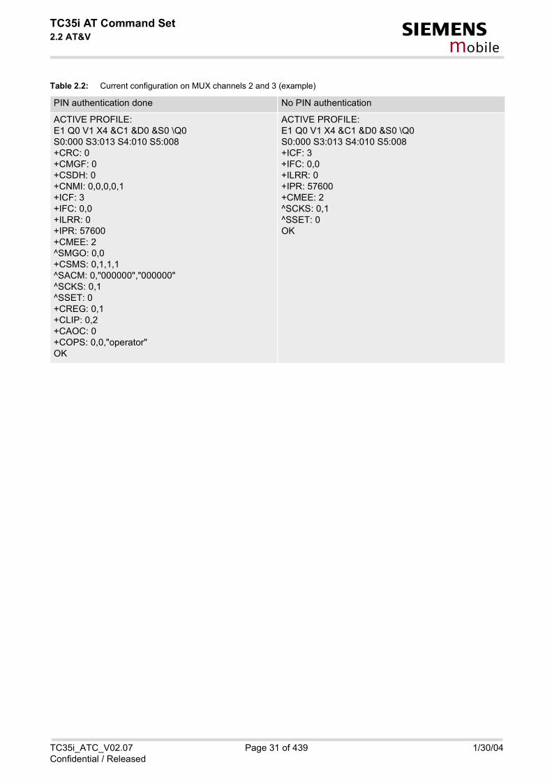
Table 2.2: Current configuration on MUX channels 2 and 3 (example)
PIN authentication done No PIN authentication
ACTIVE PROFILE:E1 Q0 V1 X4 &C1 &D0 &S0 \Q0S0:000 S3:013 S4:010 S5:008+CRC: 0+CMGF: 0+CSDH: 0+CNMI: 0,0,0,0,1+ICF: 3+IFC: 0,0+ILRR: 0+IPR: 57600+CMEE: 2^SMGO: 0,0+CSMS: 0,1,1,1^SACM: 0,"000000","000000"^SCKS: 0,1^SSET: 0+CREG: 0,1+CLIP: 0,2+CAOC: 0+COPS: 0,0,"operator"OK
ACTIVE PROFILE:E1 Q0 V1 X4 &C1 &D0 &S0 \Q0S0:000 S3:013 S4:010 S5:008+ICF: 3+IFC: 0,0+ILRR: 0+IPR: 57600+CMEE: 2^SCKS: 0,1^SSET: 0OK
TC35i_ATC_V02.07 Page 31 of 439 1/30/04Confidential / Released

TC35i AT Command Set2.3 AT&W s
mobile
2.3 AT&W Stores current configuration to user defined profile
Syntax
Command Description
TA stores the currently set parameters to a user defined profile in the non-volatile memory.
Parameter Description
[0] Number of profile
Notes
• The user defined profile will be restored automatically after PowerUp. Use ATZ to restore user profile andAT&F to restore factory settings. Until the first use of AT&W, ATZ works as AT&F.
• User defined profiles in multiplex mode:AT&W stores the current setting of each channel to the user profile, no matter on which of the three channelsthe command is executed. Each channel may have an individual profile.
• A list of parameters stored to the user profile can be found in Chapter AT Command Settings storablewith AT&W.
Exec Command
AT&W[<value>]
Response(s)
OKERROR/+CME ERROR <err>
PIN ASC0 MUX1 MUX2 MUX3
� � � � �
Reference(s)
V.25ter
<value>(num)
TC35i_ATC_V02.07 Page 32 of 439 1/30/04Confidential / Released

TC35i AT Command Set2.4 ATQ s
mobile
2.4 ATQ Set result code presentation mode
Syntax
Command Description
This parameter setting determines whether or not the TA transmits any result code to the TE. Information texttransmitted in response is not affected by this setting.
Parameter Description
[0](&F) DCE transmits result code
1 Result codes are suppressed and not transmitted
Exec Command
ATQ[<n>]
Response(s)
If <n>=0:OKIf <n>=1:(none)
PIN ASC0 MUX1 MUX2 MUX3
� � � � �
Reference(s)
V.25ter
<n>(num)(&W)(&V)
TC35i_ATC_V02.07 Page 33 of 439 1/30/04Confidential / Released
TC35i AT Command Set2.5 ATV s
mobile
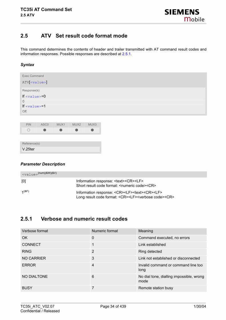
2.5 ATV Set result code format mode
This command determines the contents of header and trailer transmitted with AT command result codes andinformation responses. Possible responses are described at 2.5.1.
Syntax
Parameter Description
[0] Information response: <text><CR><LF>Short result code format: <numeric code><CR>
1(&F) Information response: <CR><LF><text><CR><LF>Long result code format: <CR><LF><verbose code><CR>
2.5.1 Verbose and numeric result codes
Exec Command
ATV[<value>]
Response(s)
If <value>=00If <value>=1OK
PIN ASC0 MUX1 MUX2 MUX3
� � � � �
Reference(s)
V.25ter
<value>(num)(&W)(&V)
Verbose format Numeric format Meaning
OK 0 Command executed, no errors
CONNECT 1 Link established
RING 2 Ring detected
NO CARRIER 3 Link not established or disconnected
ERROR 4 Invalid command or command line too long
NO DIALTONE 6 No dial tone, dialling impossible, wrong mode
BUSY 7 Remote station busy
TC35i_ATC_V02.07 Page 34 of 439 1/30/04Confidential / Released

TC35i AT Command Set2.5 ATV s
mobile
CONNECT 2400 10 Link with 2400 bps
CONNECT 4800 30 Link with 4800 bps
CONNECT 9600 32 Link with 9600 bps
CONNECT 14400 33 Link with 14400 bps
CONNECT 2400/RLP 47 Link with 2400 bps and Radio Link Pro-tocol
CONNECT 4800/RLP 48 Link with 4800 bps and Radio Link Pro-tocol
CONNECT 9600/RLP 49 Link with 9600 bps and Radio Link Pro-tocol
CONNECT 14400/RLP 50 Link with 14400 bps and Radio Link Pro-tocol
ALERTING Alerting at called phone
DIALING Mobile phone is dialing
Verbose format Numeric format Meaning
TC35i_ATC_V02.07 Page 35 of 439 1/30/04Confidential / Released

TC35i AT Command Set2.6 ATX s
mobile
2.6 ATX Set CONNECT result code format and call monitoring
Syntax
Command Description
This parameter setting determines whether or not the TA detects the presence of dial tone and busy signal andwhether or not TA transmits particular result codes.
Parameter Description
[0] CONNECT result code only returned, dial tone and busy detection are both dis-abled.
1 CONNECT <text> result code only returned, dial tone and busy detection areboth disabled.
2 CONNECT <text> result code returned, dial tone detection is enabled, busydetection is disabled.
3 CONNECT <text> result code returned, dial tone detection is disabled, busydetection is enabled.
4(&F) CONNECT <text> result code returned, dial tone and busy detection are bothenabled.
Exec Command
ATX[<value>]
Response(s)
OK
PIN ASC0 MUX1 MUX2 MUX3
� � � � �
Reference(s)
V.25ter
<value>(num)(&W)(&V)
TC35i_ATC_V02.07 Page 36 of 439 1/30/04Confidential / Released

TC35i AT Command Set2.7 AT\V s
mobile
2.7 AT\V Set CONNECT result code format
Syntax
Parameter Description
[0] CONNECT <text> result code returned without RLP trailer
1(&F) CONNECT <text> result code returned with RLP trailer
Notes
• For circuit switched data calls only.
• Output only if ATX parameter is set with value > 0.
Exec Command
AT\V[<value>]
Response(s)
OKERROR
PIN ASC0 MUX1 MUX2 MUX3
� � � � �
Reference(s)
V.25ter
<value>(num)(&W)(&V)
TC35i_ATC_V02.07 Page 37 of 439 1/30/04Confidential / Released

TC35i AT Command Set2.8 ATZ s
mobile
2.8 ATZ Set all current parameters to user defined profile
Syntax
Command Description
TA sets all current parameters to the user profile stored with AT&W. If a connection is in progress, it will be termi-nated.The user defined profile is stored to the non-volatile memory.
Parameter Description
[0] Reset to user profile
Notes
• First the profilewill be set to factory default (see AT&F). If there is a valid user profile (stored with AT&W), thisprofile will be loaded afterwards.
• Any additional commands on the same command line may be ignored. A delay of 300 ms is required beforenext command is sent, otherwise "OK" response may be corrupted.
Exec Command
ATZ[<value>]
Response(s)
OK
PIN ASC0 MUX1 MUX2 MUX3
� � � � �
Reference(s)
V.25ter
<value>(num)
TC35i_ATC_V02.07 Page 38 of 439 1/30/04Confidential / Released

TC35i AT Command Set2.9 AT+CFUN s
mobile
2.9 AT+CFUN Set phone functionality
This command serves to control the functionality level of the ME. It can be used to reset the ME, to choose oneof the SLEEP modes or to return to full functionality.Intended for power saving, SLEEP mode reduces the functionality of the ME to a minimum and thus minimizesthe current consumption. SLEEP mode falls in two categories: NON-CYCLIC SLEEP mode <fun>=0 andCYCLIC SLEEP modes, selectable as <fun>= 5, 6, 7 or 8.
NON-CYCLIC SLEEP mode permanently blocks the serial interface. The CYCLIC SLEEP mode, however, is adynamic process which alternatingly enables and disables the serial interface. The major benefit of all CYCLICSLEEP modes is that the serial interface remains accessible and that, in intermittent wake-up periods, characterscan be sent or received without terminating the selected mode. The best choice is using <fun>=7 or 8, since inthese modes TC35i automatically resumes power saving, after you have sent or received a short message ormade a call. <fun>=5 or 6 do not offer this feature to the same extent and are only supported for compatibilitywith earlier releases. In all CYCLIC SLEEP modes, you can enter <fun>=1 to permanently wake up TC35i andtake it back to full functionality. Please refer to section 2.9.1 for a summary of all SLEEP modes and the differentways of waking up the module.For CYCLIC SLEEP mode (<fun>= 5, 6, 7 or 8) both the ME and the application must be configured to use hard-ware flow control. This is necessary since the CTS signal is set/reset every time when the ME listens to a pagingmessage from the base station. This is the way how the module indicates to the application when the UART isactive. For detailed information on the timing of the CTS signal refer to [2]. The default setting of hardware flowcontrol is AT\Q0 which must be altered to AT\Q3. For use after restart you are advised to add it to the user profilesaved with AT&W.
Syntax
Test Command
AT+CFUN=?
Response(s)
+CFUN: (list of supported <fun>s) , (list of supported <rst>s) OK
Read Command
AT+CFUN?
Response(s)
+CFUN: <fun> OK
Write Command
AT+CFUN=[<fun>[, <rst>]]
Response(s)
OKERROR+CME ERROR
PIN ASC0 MUX1 MUX2 MUX3
� � � � �
TC35i_ATC_V02.07 Page 39 of 439 1/30/04Confidential / Released

TC35i AT Command Set2.9 AT+CFUN s
mobile
Command Description
The test command returns the values of the supported parameters.
The read command returns the current functionality value.
The write command can be used to reset the ME, to choose one of the SLEEP modes or to return to full func-tionality.
Parameter Description
0 NON-CYCLIC SLEEP mode: In this mode, the AT interface is not accessible. Consequently, once you haveset <fun> level 0, do not send further characters. Otherwise these charactersremain in the input buffer and may delay the output of an unsolicited resultcode. The first wake-up event stops power saving and takes the ME back to full func-tionality level <fun>=1.
[1](&F) Full functionality. If the ME is in one of the CYCLIC SLEEP modes you can issue AT+CFUN=1to stop power saving and return to full functionality. Keep in mind that, unlike the reset command described below, this action doesnot restart the ME but only changes the level of functionality. See parameter<rst> for details on the reset.
5 CYCLIC SLEEP mode: In this mode, the serial interface is shortly enabled during paging. If charactersare recognized on the serial interface, the ME stays active for 2 seconds afterthe last character was sent or received.
6 CYCLIC SLEEP mode: In this mode, the serial interface is shortly enabled during paging.If characters are recognized on the serial interface, the ME stays active for 10minutes after the last character was sent or received.To ensure that power saving takes effect immediately, the ME stays active foronly 2 seconds after <fun>=6 was entered.
7 CYCLIC SLEEP mode: In this mode, the serial interface is shortly enabled during paging. If charactersare recognized on the serial interface, the ME stays active for 2 seconds afterthe last character was sent or received. ME exits SLEEP mode only, ifAT+CFUN=1 is entered.
8 CYCLIC SLEEP mode: In this mode, the serial interface is shortly enabled during paging.If characters are recognized on the serial interface, the ME stays active for 10minutes after the last character was sent or received. ME exits SLEEP modeonly, if AT+CFUN=1 is entered.To ensure that power saving takes effect immediately, the ME stays active foronly 2 seconds after <fun>=8 was entered.
Reference(s)
GSM 07.07
<fun>(num)
TC35i_ATC_V02.07 Page 40 of 439 1/30/04Confidential / Released

TC35i AT Command Set2.9 AT+CFUN s
mobile
The parameter can only be used if the serial interface is enabled. Due to the command syntax, you need to enter parameter <fun>, followed by <rst>, where <fun> is only aplaceholder and has no effect. See examples below.
[0] Placeholder for <fun> as stated above.
1 ME resets and restarts to full functionality. After reset and restart, PIN 1authentication is necessary (AT+CPIN). If autobauding is enabled, it is recom-mended to wait 3 to 5 seconds before entering the first AT command. Fordetails on autobauding refer to chapter "4.10.1".
Notes
• In Multiplex mode, the CFUN profile is shared by all multiplexer channels.
• If the ME is in Multiplexer mode, it is not recommended to activate SLEEP mode with AT+CFUN=<fun>. Thebest approach to properly control SLEEP mode in this case is to issue the PSC messages described in [4],chapter "Power saving control".
• When a circuit-switched call is in progress, <fun>=7 or 8 can be activated without terminating the call. How-ever, setting <fun>=0, 5 or 6 during a circuit-switched call immediately disconnects this call.
• Please keep in mind that power saving works properly only when PIN authentication has been done. If youattempt to activate power saving while the SIM card is not inserted or the PIN is not correctly entered, theselected <fun> level will be set, though power saving does not take effect. For the same reason, power sav-ing cannot be used if TC35i operates in Alarm mode. Furthermore, in order to accept incoming calls, SMS ornetwork related URCs in SLEEP mode the ME must be registered when it enters the SLEEP mode.
• To check whether power saving is on, you can query the status with the read command AT+CFUN? only ifthe module is in full functionality mode or in CYCLIC SLEEP mode. If available, you can also take advantageof the status LED controlled by the SYNC pin (see AT^SSYNC and [2]). With AT^SSYNC you can select differ-ent modes of LED signalization during SLEEP modes (see 16.6.1 for details). However, the module can wakeup temporarily from power saving without leaving its CYCLIC SLEEP mode (without changing +CFUN"<fun>"), e.g. for a network scan after a loss of radio coverage, or after receipt of serial data during CYCLICSLEEP mode. During this "temporary wakeup state" the LED will operate as if the ME was in full functionalitymode.
• Recommendation: In NON-CYCLIC SLEEP mode, you can set an RTC alarm to wake up the ME and returnto full functionality. This is a useful approach because, in this mode, the AT interface is not accessible.
Examples
EXAMPLE 1
To check the level of functionality use the read command:
Remember that the AT interface is not accessible in NON-CYCLIC SLEEP mode. Consequently, the readcommand is only useful when the ME is set to full functionality or, when <fun> is set to 5, 6, 7 or 8.
<rst>(num)
AT+CFUN?
+CFUN: 1 Default mode after ME was restarted
AT+CFUN?
+CFUN: 5 CYCLIC SLEEP mode
TC35i_ATC_V02.07 Page 41 of 439 1/30/04Confidential / Released

TC35i AT Command Set2.9 AT+CFUN s
mobile
EXAMPLE 2
To set the ME to NON-CYCLIC SLEEP mode enter
When, for example, an SMS is being received and indicated by an unsolicited result code (URC), the MEwakes up to full operation.
Note that the URC used in this example will appear only, if AT+CNMI=1,1 was configured before. After this, you may want to verify the operating status:
EXAMPLE 3
To stop CYCLIC SLEEP mode and return to full functionality:
Remember that this approach is not applicable to the NON-CYCLIC SLEEP mode (since the serial interfaceis disabled). The NON-CYCLIC SLEEP mode ends with the first wake-up event.
EXAMPLE 4
To reset and restart the ME:
2.9.1 Wake up the ME from SLEEP modeA wake-up event is any event that switches off the SLEEP mode and causes the ME to return to full functionality.In short, it takes the ME back to AT+CFUN=1.Definitions of the state transitions described in the table below:
• Yes means: ME exits SLEEP mode• No means: ME does not exit SLEEP mode
AT+CFUN=0
OK
+CMTI: "SM",5
AT+CFUN?
+CFUN: 1 Indicates that ME has entered full functionality mode.
AT+CFUN?
+CFUN: 5
OK
AT+CFUN=1
OK
AT+CFUN=1,1 or alternatively, AT+CFUN=0,1 or 5,1 or 6,1 or 7,1 or 8,1 OK
^SYSSTART The ^SYSSTART URC confirms that the ME has been rebooted. Note that ^SYSSTART appears only if AT+IPR � 0. If the ME is in autobaud mode, it is recommended to wait 3 to 5 seconds before entering the first AT command. Remember to enter the SIM PIN after restart.
Event From <fun>=0 to <fun>=1
From <fun>=5 or 6 to <fun>=1
From <fun>=7 or 8 to <fun>=1
Ignition line No No No
/RTS0 Yes No No
TC35i_ATC_V02.07 Page 42 of 439 1/30/04Confidential / Released

TC35i AT Command Set2.9 AT+CFUN s
mobile
Unsolicited Result Code (URC)
Yes Yes No
Incoming voice or data call
Yes Yes No
Any AT command (incl. outgoing SMS, voice or data call)
Not possible (UART dis-abled)
No No
Incoming SMS (AT+CNMI is set to 0,0 (this is the default setting)
No No No
Incoming SMS (AT+CNMI is set to 1,1)
Yes Yes No
RTC alarm line Yes Yes No
AT+CFUN=1 Not possible (UART dis-abled)
Yes Yes
Event From <fun>=0 to <fun>=1
From <fun>=5 or 6 to <fun>=1
From <fun>=7 or 8 to <fun>=1
TC35i_ATC_V02.07 Page 43 of 439 1/30/04Confidential / Released
TC35i AT Command Set2.10 AT^SMSO s
mobile
2.10 AT^SMSO Switch off mobile station
Syntax
Unsolicited Result Code
^SHUTDOWN
Indicates that the power-off procedure is finished and the module will be switched off within 1 second
Command Description
The exec command initiates the power-off procedure. Low level of the module's VDD pin and display of URC"^SHUTDOWN" verifies that the procedure has completed and the module has entered the POWER DOWN mode.Therefore, be sure not to disconnect the operating voltage until VDD is low or until URC "^SHUTDOWN" is dis-played . Otherwise, you run the risk of losing data. For further details on how to turn off the module see the [2].
Notes
• Do not send any command after this command.
• If AT^SMSO is entered on one of the Multiplexer channels the ME closes the Multiplexer channels, terminatesthe Multiplexer and deactivates all other functions. Then, the URC "^SHUTDOWN" will be issued on the phys-ical serial interface (ASC0). The URC will be transmitted at the bit rate last activated on ASC0 for use withthe Multiplex driver.
Test Command
AT^SMSO=?
Response(s)
OK
Exec Command
AT^SMSO
Response(s)
^SMSO: MS OFFOK
PIN ASC0 MUX1 MUX2 MUX3
� � � � �
Reference(s)
SIEMENS
TC35i_ATC_V02.07 Page 44 of 439 1/30/04Confidential / Released

TC35i AT Command Set2.11 AT+GCAP s
mobile
2.11 AT+GCAP Request complete TA capabilities list
Syntax
Command Description
TA reports a list of additional capabilities.
Parameter Description
e.g.: +CGSM,+FCLASS
Note
• +CGSM: The response text shows which GSM commands of the ETSI standard are supported.
Test Command
AT+GCAP=?
Response(s)
OK
Exec Command
AT+GCAP
Response(s)
+GCAP: <name> OK
PIN ASC0 MUX1 MUX2 MUX3
� � � � �
Reference(s)
V.25ter
<name>(str)
TC35i_ATC_V02.07 Page 45 of 439 1/30/04Confidential / Released

TC35i AT Command Set2.12 AT+CMEE s
mobile
2.12 AT+CMEE Report mobile equipment error
Syntax
Command Description
This command controls the presentation of the result code +CME ERROR: <err> that indicates errors relating toME functionality.When you power down or reset the ME with AT+CFUN=1,1 the setting will be reset to its default. The levels 1 or2 need to be selected every time you reboot the ME, or may be included, for permanent use, in the user profilesaved with AT&W.
Parameter Description
0(&F) disable result code (only 'ERROR' will be displayed)
1 enable result code and use numeric values
2 enable result code and use verbose values
Test Command
AT+CMEE=?
Response(s)
+CMEE: (list of supported<n>s) OK
Read Command
AT+CMEE?
Response(s)
+CMEE: <n> OK
Write Command
AT+CMEE=<n>
Response(s)
OKERROR+CME ERROR: <err>
PIN ASC0 MUX1 MUX2 MUX3
� � � � �
Reference(s)
GSM 07.07
<n>(num)(&W)(&V)
TC35i_ATC_V02.07 Page 46 of 439 1/30/04Confidential / Released

TC35i AT Command Set2.12 AT+CMEE s
mobile
Notes
• The possible error result codes are listed in 2.12.1 and 2.12.2.
• In multiplex mode (see AT+CMUX) the setting applies only to the logical channel where selected. The settingon the other channels may differ.
Example
To obtain enhanced error messages it is recommended to choose <n>=2.
2.12.1 Summary of CME ERRORS related to GSM 07.07
AT+CMEE=2
OK
Code of <err> Text (if AT+CMEE=2)
0 phone failure
1 no connection to phone
2 phone-adapter link reserved
3 Operation not allowed
4 Operation not supported
5 PH-SIM PIN required
6 PH-FSIM PIN required
7 PH-FSIM PUK required
10 SIM not inserted
11 SIM PIN required
12 SIM PUK required
13 SIM failure
14 SIM busy
15 SIM wrong
16 Incorrect password
17 SIM PIN2 required
18 SIM PUK2 required
20 Memory full
21 invalid index
22 not found
23 Memory failure
24 text string too long
25 invalid characters in text string
26 dial string too long
TC35i_ATC_V02.07 Page 47 of 439 1/30/04Confidential / Released

TC35i AT Command Set2.12 AT+CMEE s
mobile
2.12.2 Summary of CMS ERRORS related to GSM 07.05
27 invalid characters in dial string
30 no network service
31 Network timeout
32 Network not allowed emergency calls only
40 Network personalization PIN required
41 Network personalization PUK required
42 Network subset personalization PIN required
43 Network subset personalization PUK required
44 service provider personalization PIN required
45 service provider personalization PUK required
46 Corporate personalization PIN required
47 Corporate personalization PUK required
48 Master Phone Code required
100 Unknown
132 service option not supported
133 requested service option not subscribed
134 service option temporarily out of order
256 Operation temporary not allowed
257 call barred
258 phone is busy
259 user abort
260 invalid dail string
261 ss not executed
262 SIM blocked
Code of <err> Text (if AT+CMEE=2)
1 Unassigned (unallocated) number
8 Operator determined barring
10 Call barred
21 Short message transfer rejected
27 Destination out of service
28 Unidentified subscriber
29 Facility rejected
30 Unknown subscriber
38 Network out of order
Code of <err> Text (if AT+CMEE=2)
TC35i_ATC_V02.07 Page 48 of 439 1/30/04Confidential / Released

TC35i AT Command Set2.12 AT+CMEE s
mobile
41 Temporary failure
42 Congestion
47 Resources unavailable, unspecified
50 Requested facility not subscribed
69 Requested facility not implemented
81 Invalid short message transfer reference value
95 Invalid message, unspecified
96 Invalid mandatory information
97 Message type non-existent or not implemented
98 Message not compatible with short message protocol state
99 Information element non-existent or not implemented
111 Protocol error, unspecified
127 Interworking, unspecified
128 Telematic interworking not supported
129 Short message Type 0 not supported
130 Cannot replace short message
143 Unspecified TP-PID error
144 Data coding scheme (alphabet) not supported
145 Message class not supported
159 Unspecified TP-DCS error
160 Command cannot be actioned
161 Command unsupported
175 Unspecified TP-Command error
176 TPDU not supported
192 SC busy
193 No SC subscription
194 SC system failure
195 Invalid SME address
196 Destination SME barred
197 SM Rejected-Duplicate SM
198 TP-VPF not supported
199 TP-VP not supported
208 D0 SIM SMS storage full
209 No SMS storage capability in SIM
210 Error in MS
211 Memory Capacity Exceeded
212 SIM Application Toolkit Busy
Code of <err> Text (if AT+CMEE=2)
TC35i_ATC_V02.07 Page 49 of 439 1/30/04Confidential / Released

TC35i AT Command Set2.12 AT+CMEE s
mobile
213 SIM data download error
255 Unspecified error cause
300 ME failure
301 SMS service of ME reserved
302 Operation not allowed
303 Operation not supported
304 Invalid PDU mode parameter
305 Invalid text mode parameter
310 SIM not inserted
311 SIM PIN required
312 PH-SIM PIN required
313 SIM failure
314 SIM busy
315 SIM wrong
316 SIM PUK required
317 SIM PIN2 required
318 SIM PUK2 required
320 Memory failure
321 Invalid memory index
322 Memory full
330 SMSC address unknown
331 no network service
332 Network timeout
340 NO +CNMA ACK EXPECTED
500 Unknown error
512 User abort
513 unable to store
514 invalid status
515 invalid character in address string
516 invalid length
517 invalid character in pdu
518 invalid parameter
519 invalid length or character
520 invalid character in text
521 timer expired
522 Operation temporary not allowed
Code of <err> Text (if AT+CMEE=2)
TC35i_ATC_V02.07 Page 50 of 439 1/30/04Confidential / Released

TC35i AT Command Set2.13 AT+CSCS s
mobile
2.13 AT+CSCS Select TE character set
Syntax
Command Description
Write command informs TA which character set <chset> is used by the TE. TA is then able to convert characterstrings correctly between TE and ME character sets.
Parameter Description
“GSM“(&F) GSM default alphabet (GSM 03.38 subclause 6.2.1);Note: This setting may cause software flow control problems since the codesused to stop and resume data flow (XOFF = decimal 19, (XON = decimal 17)are interpreted as normal characters.
“UCS2“ 16-bit universal multiple-octet coded character set (ISO/IEC10646 [32]); UCS2character strings are converted to hexadecimal numbers from 0000 to FFFF;e.g. "004100620063" equals three 16-bit characters with decimal values 65, 98and 99, $(AT R97)$
Test Command
AT+CSCS=?
Response(s)
+CSCS: (list of supported<chset>s) OK
Read Command
AT+CSCS?
Response(s)
+CSCS: <chset> OK
Write Command
AT+CSCS=[<chset>]
Response(s)
OK
PIN ASC0 MUX1 MUX2 MUX3
� � � � �
Reference(s)
GSM 07.07, GSM 11.11
<chset>(str)
TC35i_ATC_V02.07 Page 51 of 439 1/30/04Confidential / Released

TC35i AT Command Set2.13 AT+CSCS s
mobile
Notes
• Also see chapter "Supported character sets".
• When TA-TE interface is set to 8-bit operation and used TE alphabet is 7-bit, the highest bit will be set to zero.
TC35i_ATC_V02.07 Page 52 of 439 1/30/04Confidential / Released
TC35i AT Command Set2.14 AT^SCFG s
mobile
2.14 AT^SCFG Extended Configuration Settings
This command can be used to query and configure various settings of the TC35i.
Syntax
Unsolicited Result Code
^SCFG: "AutoExec", <AutoExecState>, <AutoExecType>, <AutoExecIndex>, <AutoExecMode>, <AutoExecATC>
If the event specified with <AutoExecType> occurs and the related AT command line is executed this URC isissued.
Test Command
AT^SCFG=?
Response(s)
^SCFG: "AutoExec" , (list of supported <AutoExecCmd>), (list of supported <AutoExecType>), (list of supported <AutoExecIndex>), (list of supported <AutoExecMode>), (max. string length of <AutoExecATC>), (time range of <AutoExecPeriod>)OK
Read Command
AT^SCFG?
Response(s)
^SCFG: "AutoExec" , <AutoExecCmd>, <AutoExecType>, <AutoExecIndex>, <AutoExecMode>, <AutoExecATC>[, <AutoExecPeriod>]OK
Write Command
Automatic AT command execution
AT^SCFG="AutoExec" , <AutoExecCmd>, <AutoExecType>, <AutoExecIndex>[, <AutoExecMode>, <AutoExecATC>[, <AutoExecPeriod>]]
Response(s)
^SCFG: "AutoExec" , <AutoExecCmd>, <AutoExecType>, <AutoExecIndex>, <AutoExecMode>, <AutoExecATC>[, <AutoExecPeriod>]OKERROR+CME ERROR
PIN ASC0 MUX1 MUX2 MUX3
� � � � �
Reference(s)
SIEMENS
TC35i_ATC_V02.07 Page 53 of 439 1/30/04Confidential / Released

TC35i AT Command Set2.14 AT^SCFG s
mobile
Command Description
The read command returns a list of all supported parameter and their current values.
The write command allows to query a configuration parameter (if no value is entered) or to set its value(s). Input of parameter names is always coded in GSM character set, parameter values are expected to be given asspecified via AT+CSCS. The following error codes may be responded: • "+CME ERROR: operation temporary not allowed" ... change of parameter value(s) temporarily not allowed• "+CME ERROR: invalid index" ... invalid parameter name or invalid value(s).• "+CME ERROR: invalid characters in text string" ... a character set conversion of parameter value(s) failed• "+CME ERROR: operation not allowed" ... change of parameter value(s) not allowed• "+CME ERROR: unknown" ... other errors
Parameter Description
AutoExec CommandThis parameter specifies the AT command action type. If the action type is set to '0', parameters following <AutoExecIndex> will be ignored and all values at the givenindex are restored to their default values. Value will be saved while switching off the TC35i via AT commands (e.g. AT+CFUN or AT^SMSO) and restoredon next power up.
“0“ Disable execution of AT command at given index.
“1“ Enable execution of AT command at given index. Not allowed for <AutoEx-ecType>=0 (DTR line activation) while multiplex mode is active, refer toAT+CMUX.
AutoExec Command StatusThis parameter shows the current AT command status. Value will be saved while switching off the TC35i via AT commands (e.g. AT+CFUN or AT^SMSO) and restoredon next power up.
“0“ Execution of related AT command is disabled.
“1“ Execution of related AT command is enabled.
AutoExec Event TypeThis parameter specifies the kind of event that may be configured to automatically launch an AT command. Value will be saved while switching off the TC35i via AT commands (e.g. AT+CFUN or AT^SMSO) and restoredon next power up.
“0“ ASC0 DTR line activation (OFF-ON transition).
“1“ Time span specified with <AutoExecPeriod> expires.
<AutoExecCmd>(str)(+CSCS)
<AutoExecState>(str)(+CSCS)
<AutoExecType>(str)(+CSCS)
TC35i_ATC_V02.07 Page 54 of 439 1/30/04Confidential / Released

TC35i AT Command Set2.14 AT^SCFG s
mobile
AutoExec AT command StringThis parameter specifies the automatically launched AT command. It is executed as entered online, e.g. com-mand concatenation is possible if supported by the given commands. If serial multiplex mode is activated(AT+CMUX) the first logical channel is used, i.e. CSD calls (data or fax) could be set up. If the TC35i is busy onthe serial channel command execution will be delayed until ongoing action is finished. In contrast with AT%D repeated autoexecution events are not ignored during a call triggered by such an event. The first two characters of the automatically launched AT command shall be "at" and its length shall be less than25 characters. Please refer to examples below. Value will be saved while switching off the TC35i via AT commands (e.g. AT+CFUN or AT^SMSO) and restoredon next power up.
AutoExec Command ModeThis parameter specifies details regarding the behavior of the TC35i when the AT command starts to be exe-cuted. Value is interpreted as a bit field, unused bits are reserved for future use (RFU) and shall be set to 0.
When a call is released by autoexec activity, no release indication may be issued on the first logical channel. If during a data call the TC35i temporarily enters command mode via +++ no AT command will be executed if<AutoExecMode> specifies 'Ignore ongoing calls'. Value will be saved while switching off the TC35i via AT commands (e.g. AT+CFUN or AT^SMSO) and restoredon next power up.
0...255
AutoExec Command IndexThis parameter specifies the command storage index. If the range comprises more than one storage the related<AutoExecType> variant may be started in parallel with different parameter settings. The following table shows the index ranges of the different <AutoExecType> variants.
<AutoExecATC>(str)(+CSCS)
<AutoExecMode>(str)(+CSCS)
Bit Maskhex Maskdec Control
D0D1
0x00 0x01 0x02 0x03
0 1 2 3
00: Ignore ongoing calls 01: Wait for all calls have ended 10: Dismiss any ongoing call 11: RFU
D2 0x04 4 0: One shot action 1: Periodically action (for "AutoExec/Period" only)
D3 0x08 8 RFU
D4 0x10 16 RFU
D5 0x20 32 RFU
D6 0x40 64 RFU
D7 0x80 128 RFU
<AutoExecIndex>(str)(+CSCS)
TC35i_ATC_V02.07 Page 55 of 439 1/30/04Confidential / Released

TC35i AT Command Set2.14 AT^SCFG s
mobile
Value will be saved while switching off the TC35i via AT commands (e.g. AT+CFUN or AT^SMSO) and restoredon next power up.
AutoExec AT Command PeriodParameter specifies the period after which <AutoExecATC> will be executed. Format is "hhh:mm:ss", wherecharacters indicate hours and minutes. This parameter applies for <AutoExecPeriod>=1 only. Due to the internal activity and network signalling an execution delay of several seconds may occur for the over-all procedure. Value will be saved while switching off the TC35i via AT commands (e.g. AT+CFUN or AT^SMSO) and restoredon next power up.
000:00:05...240:00:00
Notes
• Automatic dialing on DTR line activation can also be enabled via AT%D. However, AT%D and <AutoExec-Type>=0 shall not be used at the same time. If both kinds of DTR triggered autoexecution are enabled onlyAT%D related action will be performed.
• Please keep in mind, that each time the ME is restarted the timers of all autoexec actions configured with<AutoExecType>=1 and <AutoExecPeriod> will be reinitialized and restarted. As a result, an autoexecaction configured at a time later then a scheduled automatic restart would never be executed.
• Please be careful using <AutoExecType>=1 with small period values and shutdown or reset AT commands,since only little time remains to change these settings again after TC35i restart.
• If <AutoExecATC> uses AT commands containing secret data, this information may be retrieved withAT^SCFG?. For instance, this applies if using AT+CPIN.
<AutoExecType> value
<AutoExecType> event
Valid Indicies
0 ASC0 DTR line activation 0
1 <AutoExecPeriod> expiration 0-2
<AutoExecPeriod>(str)(+CSCS)
TC35i_ATC_V02.07 Page 56 of 439 1/30/04Confidential / Released

TC35i AT Command Set2.14 AT^SCFG s
mobile
Examples
EXAMPLE 1
Enable sending of a short message (SMS) on next DTR activation (OFF-ON transition). Sent SMS isassumed to be stored at first location of storage selected with AT+CPMS and AT^SSMSS, i.e. SMS may besent from either SIM or ME storage. Also refer to AT+CMSS and AT+CMGW. Since SMS transmission and ongoing calls are possible at the sametime there is no need to wait until all calls have ended. (<AutoExecMode>=0).
If a DTR activation has occured the ME issues the URC "^SCFG: " followed by the response of the executedcommand; the message reference in this case:
EXAMPLE 2
Perform a reset with the TC35i periodically after 10 hours, but wait for all calls have ended. For details regarding software controlled power down refer to AT+CFUN and AT^SMSO.
After ten hours:
AT+CMGF=1 Enable SMS text modeOK
AT+CNMI=1,1 Enable "+CMTI:" URC on any received SMSOK
AT+CMGD=1 Delete first SMS locationOK
AT+CMGW="01522400045",145 Store an SMS with>Test-SMS to be sent from storage! text entry (finish with CTRL-Z)+CMGW: 1 SMS confirmed to be stored at first locationOK
AT^SCFG="AutoExec",1,0,0,0,"AT+CMSS=1" Enable execution on next DTR activation^SCFG: "AutoExec","1","0","0","0","at+cmss=1"
^SCFG: "AutoExec","0","1","0","0","","000:00:00","000:00:00"
^SCFG: "AutoExec","0","1","1","0","","000:00:00","000:00:00"
^SCFG: "AutoExec","0","1","2","0","","000:00:00","000:00:00"
OK
^SCFG:"AutoExec",0,0,1,0,"AT+CMSS=1"
OK "AT+CMSS=1" command entry confirmation+CMSS: 16
AT^SCFG="AutoExec",1,1,2,5,"AT+CFUN=0,1","010:00:00"
...
OK
^SCFG:"AutoExec",1,1,2,5,"AT+CFUN=0,1"
OK "AT+CFUN=0,1" command entry confirmationSYSSTART TC35i has restarted
TC35i_ATC_V02.07 Page 57 of 439 1/30/04Confidential / Released

TC35i AT Command Set2.14 AT^SCFG s
mobile
EXAMPLE 3
Switch off the TC35i after three minutes without restart. For details regarding software controlled power down refer to AT+CFUN and AT^SMSO.
After three minutes:
AT^SCFG="AutoExec",1,1,3,0,"AT^SMSO","000:03:00"
...
OK
^SCFG:"AutoExec",0,1,3,0,"AT^SMSO"
OK "AT^SMSO" command entry confirmation^SHUTDOWN "AT^SMSO" command response
TC35i_ATC_V02.07 Page 58 of 439 1/30/04Confidential / Released

TC35i AT Command Set2.15 AT^SM20 s
mobile
2.15 AT^SM20 Set M20 compatibility mode
Syntax
Command Description
M20 is an earlier, widely used SIEMENS GSM engine. The AT^SM20 command selects different modes ofresponses returned upon execution of the commands ATD and sms commands like e.g. AT+CMGW. Please notethat the AT^SM20 command has no effect on any other features and is not intended to adjust other differencesbetween M20 and TC35i.
Test Command
AT^SM20=?
Response(s)
OK
Read Command
AT^SM20?
Response(s)
^SM20:<CallMode>, <CmgwMode> OK
Write Command
AT^SM20=<CallMode>[, <CmgwMode>]
Response(s)
OK
PIN ASC0 MUX1 MUX2 MUX3
� � � � �
Reference(s)
SIEMENS
TC35i_ATC_V02.07 Page 59 of 439 1/30/04Confidential / Released

TC35i AT Command Set2.15 AT^SM20 s
mobile
Parameter Description
Call setup response modeApplies only to voice calls.
0 Set compatibility to Siemens mobile phones.ME will return "OK" immediately after attempting a call with the ATD command.In case of failure, additional call release indications, such as "NO DIAL TONE,"NO CARRIER", "BUSY" will follow.
1(&F) Default call setup mode, compatible to M20.ME will return "OK" in case of a successful connection, otherwise one of thecall release indications "NO DIAL TONE, "NO CARRIER", "BUSY" are indi-cated.
Response mode for sending and writing short messagesApplies to the sms commands like e.g. AT+CMGS and AT+CMGW command.
0 Set compatibility to Siemens mobile phones.ME will return +CMS ERROR: <err> when writing or sending of short mes-sages fails.
1(&F) Default mode for sending and writing short messages, compatible to M20.ME will return "OK", no matter whether or not sms command was successfullyexecuted.
<CallMode>(num)
<CmgwMode>(num)
TC35i_ATC_V02.07 Page 60 of 439 1/30/04Confidential / Released

TC35i AT Command Set3. Status Control Commands s
mobile
3. Status Control Commands
The AT Commands described in this chapter allow the external application to obtain various status information from the TC35i.
3.1 AT+CMER Mobile Equipment Event Reporting
This command controls details of the "+CIEV" URC presentation related to AT^SIND and AT+CIND. If registeredvia these commands the URCs are sent whenever a value of the related indicator changes. After AT+CMER has been switched on, URCs for all registered indicators will be issued.
Syntax
Test Command
AT+CMER=?
Response(s)
+CMER: (list of supported<mode>s), (list of supported<keyp>s), (list of supported<disp>s), (list of supported<ind>s), (list of supported<bfr>s) OK
Read Command
AT+CMER?
Response(s)
+CMER: <mode>, <keyp>, <disp>, <ind>, <bfr> OK
Write Command
AT+CMER=[<mode>[, <keyp>[, <disp>[, <ind>[, <bfr>]]]]]
Response(s)
OKERROR+CME ERROR
PIN ASC0 MUX1 MUX2 MUX3
� � � � �
Reference(s)
GSM 07.07
TC35i_ATC_V02.07 Page 61 of 439 1/30/04Confidential / Released

TC35i AT Command Set3.1 AT+CMER s
mobile
Unsolicited Result Code
+CIEV: <indDescr>, <indValue>
A value of an indicator has changed.
Command Description
The read command returns the URC presentation mode <mode> and among others, the indicator event reportingstatus <ind>.
The write command enables and disables the presentation of "+CIEV: <indDescr>, <indValue>" URCs.<indDescr> refers to the name of a "+CIEV" indicator and <indValue> is the new value of this indicator. Allregistered indicator events will be issued to the TE.
Parameter Description
0(&F) Discard "+CIEV" URCs.
1 Discard "+CIEV" URCs when TA-TE link is reserved, e.g. in online data mode.Otherwise they are forwarded directly to the TE.
2 Buffer "+CIEV" URCs in the TA while TA-TE link is reserved, e.g. in online datamode, and flush them to the TE afterwards. Otherwise they are forwardeddirectly to the TE.
3 Forward "+CIEV" URCs directly to the TE. If TC35i is in online data mode,URCs are signaled via sending BREAK (100ms) and stored in a buffer. Onceit is back in command mode e.g. after +++ was entered, all URCs stored in thebuffer will be output.
0(&F) Keypad event reporting is not supported by TC35i.
0(&F) Display event reporting is not supported by TC35i.
0(&F) Disable indicator event reporting.
2 Enable indicator event reporting.
0(&F) TA buffer of URCs defined within this command is cleared when <mode> 1..3is entered.
Name of indicator; for a list of all supported indicators please refer to AT+CIND and AT^SIND.
Value of indicator; for a list of all values for the supported indicators please refer to AT+CIND and AT^SIND.
<mode>(num)(&W)
<keyp>(num)
<disp>(num)
<ind>(num)(&W)
<bfr>(num)
<indDescr>(str)
<indValue>(num)
TC35i_ATC_V02.07 Page 62 of 439 1/30/04Confidential / Released
TC35i AT Command Set3.1 AT+CMER s
mobile
Note
• If the ME operates on different instances (MUX channels 1, 2, 3) avoid different settings for routing and indi-cating SMS. For example, if messages shall be routed directly to one instance of the TE (set with AT+CNMI,AT^SSDA), it is not possible to activate the presentation of URCs with AT+CMER or AT+CNMI on anotherinstance. Any attempt to activate settings that conflict with existing settings on another interface, will result inCME ERROR, or accordingly CMS ERROR.
TC35i_ATC_V02.07 Page 63 of 439 1/30/04Confidential / Released

TC35i AT Command Set3.2 AT+CIND s
mobile
3.2 AT+CIND Indicator control
This command controls information about status changes via URC presentation of the $product; or connecteditems, e.g. battery charge level, signal quality, service availability, sound generation, indication of unread shortmessages, full SMS storage, call in progress or roaming activities. Use of this command is outdated since additional indications and functionality are available with AT^SIND.
AT+CIND supports two ways to get the values related to indicators: • Query the current status of each indicator by using the read command AT+CIND?. It returns the status no
matter whether the indicator has been registered with the write commandAT+CIND=[<state>[,<state>[,...]]].
• Evaluate one of the "+CIEV" URCs which the ME automatically sends to the application, whenever the valueof the associated indicator changes. The presentation of these URCs depends on two settings: - The indicators must be registered with the write command AT+CIND=[<state>[,<state>[,...]]]. By
default, all of them are registered when the ME is switched on. Any URC can be excluded if deregisteredwith <state>=0.
- URC presentation must be enabled with AT+CMER.
Syntax
Test Command
AT+CIND=?
Response(s)
+CIND: (<indDescr>, list of supported <indValue>s)[, (<indDescr>, list of supported <indValue>s)[, ...]]OK
Read Command
AT+CIND?
Response(s)
+CIND: <indValue>[, <indValue>[, ...]]OKERROR+CME ERROR: <err>
Write Command
AT+CIND=<state>[, <state>[, ...]]
Response(s)
OKERROR+CME ERROR: <err>
TC35i_ATC_V02.07 Page 64 of 439 1/30/04Confidential / Released

TC35i AT Command Set3.2 AT+CIND s
mobile
Command Description
The read command returns the status of the ME indicators.
The write command is used to switch the event report for each indicator type. The Indicator Event Reports aredisplayed to the TE via "+CIEV" which can be enabled using AT+CMER.
Parameter Description
Integer type value, which shall be in range of corresponding <indDescr>
String values and their <indValue> ranges.More indications are available via AT^SIND. Therefore use of AT^SIND for control of all indications is recom-mended.The following indications are accessible via AT+CIND:
“battchg“ Battery charge level 0..4 or 5 if no measuring is performed, e.g because no bat-tery is connected. Also refer AT^SBC.
“signal“ Signal quality (0..7) or (99) if not measurable. The indicated value is the biterror rate of the signal received. If there are bit errors this is not a constant buta estimated value which will change in time. See also AT+CSQ.
“service“ Service availability (0-1)0: Not registered to any network1: Registered to home network or, if "roam"=1 then registered to another net-work
“sounder“ Sounder activity (0-1). The indicator provides information about tones gener-ated in the ME. Value 1 means for example:Incoming call - ME is ringing. Note that the URC "+CIEV": "sounder" indicatorwill be output only if ringing tones are activated with AT^SRTC.Waiting call - ME generates waiting call tone (if call waiting is enabled).Outgoing call - ME generates Call Progress tone.Outgoing call - ME generates BUSY tone.The value changes to 0 if tone stops
“message“ Unread short message at memory location <mem1> (0-1); refer to AT+CPMS
“call“ Call in progress (0-1). Indicator value is "1" if at least one call is in state "active"or "held".
“roam“ Roaming indicator (0-1)0: Registered to home network or not registered1: Registered to other network
PIN ASC0 MUX1 MUX2 MUX3
� � � � �
Reference(s)
GSM 07.07
<indValue>(num)
<indDescr>(str)
TC35i_ATC_V02.07 Page 65 of 439 1/30/04Confidential / Released
TC35i AT Command Set3.2 AT+CIND s
mobile
“smsfull“ A short message memory storage in the MT has become full (1) or memorylocations are available (0), i.e. range is (0-1)
“rssi“ Received signal (field) strength (0..5) or (99) if not measurable.0: signal strength <= -112 dbm1-4: signal strength in 15 dbm steps5: signal strength >= -51 dbmReceived signal (field) strength can also be obtained with AT+CSQ. However,the signal strength is scaled to value range 0..31 by this command.
0 Indicator is deregistered. The indicator will not be presented as "+CIEV" URC,but can be queried with AT+CIND?.
[1](P) Indicator is registered, indicator event report allowed.
Notes
• Due to its restrictive range of values, there are events when it is not entirely clear from the context, whichevent has led to the output of indicator "call". Rather than as an information in itself, indicator "call" shouldtherefore be used as a trigger to look up the new call status in the list of current calls with AT commandsAT+CLCC or AT^SCNI.
• The indicator "sounder" signals every event a tone is generated in the ME. For instance, if a waiting call pro-duces a tone, this will be indicated.
• If the ME is switched on all indicators are in registered state.
• Use AT+CMER command to allow Indicator Event Report of all registered indicators.
Example
<state>(num)
^SYSSTART
AT+CPIN=9999
OK
AT+CIND?
+CIND: 5,99,1,0,0,0,0,0,5 The battery is either full or no battery is connected to the ME. The bit error rate of the signal quality is not available (since there is no call in progress). The ME is registered to its home network.
OK
AT+CMER=2,0,0,2 Now activate the Indicator Event Report with AT+CMER.
OK
+CIEV: battchg,5
+CIEV: signal,99
+CIEV: service,1
+CIEV: sounder,0
+CIEV: message,0
+CIEV: call,0
+CIEV: roam,0
TC35i_ATC_V02.07 Page 66 of 439 1/30/04Confidential / Released

TC35i AT Command Set3.2 AT+CIND s
mobile
+CIEV: smsfull,0
+CIEV: rssi,5 Receive with full signal field strengthATD0123456; Make a call.OK
+CIEV: sounder,1 Receive a set of "+CIEV" URCs reports.+CIEV: call,1
+CIEV: sounder,0
+CIEV: call,0 The receiver hangs up.NO CARRIER
AT+CIND=,,,0,,0 Deregister the indicators "call" and "sounder"OK
ATD0123456; Rebuild the same call.OK
This time, no URCs are displayed.NO CARRIER
TC35i_ATC_V02.07 Page 67 of 439 1/30/04Confidential / Released

TC35i AT Command Set3.3 AT^SIND s
mobile
3.3 AT^SIND Extended Indicator Control
AT^SIND supplies extended event indicator control and • offers greater flexibility than standard AT+CIND, • offers several extra indicators, • can show the current status of all indicators supported by AT+CIND and AT^SIND, • gives the possibility to register or deregister the indicators of both commands, • displays all indicator event reports via "+CIEV" URCs. Presentation mode of the generated URCs is controlled via AT+CMER.
Syntax
Test Command
AT^SIND=?
Response(s)
^SIND: (<indDescr>, list of supported <indValue>s)[, (<indDescr>, list of supported <indValue>s)[, ...]], (list of supported <Mode>s) OK
Read Command
AT^SIND?
Response(s)
^SIND: <indDescr>, <Mode>, <indValue> OKERROR+CME ERROR: <err>
Write Command
AT^SIND=<indDescr>, <Mode>
Response(s)
OKERROR+CME ERROR: <err>
PIN ASC0 MUX1 MUX2 MUX3
� � � � �
Reference(s)
SIEMENS
TC35i_ATC_V02.07 Page 68 of 439 1/30/04Confidential / Released

TC35i AT Command Set3.3 AT^SIND s
mobile
Command Description
The read command provides a list of all indicators supported by AT+CIND and AT^SIND. Each indicator is rep-resented with its registration mode and current value.
The write command can be used to select a single indicator in order to modify its registration and to view thecurrent value.
Parameter Description
Integer type value in the range stated below for the corresponding <indDescr>
String values and their <indValue> ranges.All indicators supported by AT+CIND are accessible with this command, too. A detailed description of these indi-cators can be found there.The following indicators are accessible via AT^SIND only:
“ciphcall“ Ciphering Status Change Indication As stated in GSM specifications 02.07 and 02.09 the ciphering indicator featureallows the ME to detect that ciphering is not switched on and to indicate this tothe user. The ciphering indicator feature may be disabled by the home network operatorsetting data in the "administrative data" field (EFAD) in the SIM, as defined inGSM 11.11. If this feature is not disabled by the SIM, then whenever a connection is inplace, which is, or becomes unenciphered, an indication shall be given to theuser. This enables the user's decision how to proceed. Read command returns valid ciphering status only if a call is in progress oractive. If EFADsetting disables the ciphering indicator feature read command alwaysindicates a ciphered link and no URC presentaion will take place. Note:The following restrictions apply if the same serial channel is used for AT^SIND"ciphcall" indication and for the action triggering this URC. In general, the rec-ommended solution is to use a dedicated channel for all status signalling viaURCs. • If an unciphered mobile originated SMS is performed, AT^SIND "ciphcall"
URCs on the same serial channel will be issued after the related "OK" andindicate the ciphering state at this time. Because the SMS is already sent atthis time, you will get 2 URCs on this channel, but both are indicating thatciphering is enabled.
• If an unciphered mobile originated data call is performed, AT^SIND "ciph-call" URCs on the same serial channel will be issued after the interface isnot longer blocked by the call (call is released or temporarily stopped) andindicate the ciphering state at this time.
0 .. Current call or SMS is not ciphered. 1 .. Current call or SMS is ciphered.
0 Indicator is deregistered, i.e. no such indicator event report (URC) will beissued.
1 Indicator is registered.
<indValue>(num)
<indDescr>(str)
<Mode>(num)
TC35i_ATC_V02.07 Page 69 of 439 1/30/04Confidential / Released

TC35i AT Command Set3.3 AT^SIND s
mobile
• Indicator event reports are controlled via AT+CMER. • Indicators defined by AT^SIND remain deregistered until explicitly enabled. • On the other hand indicators supported by AT+CIND are registered while
the TC35i is powered up.
2 Query the registration status and the current value of a single indicator type.
TC35i_ATC_V02.07 Page 70 of 439 1/30/04Confidential / Released

TC35i AT Command Set3.4 AT+CEER s
mobile
3.4 AT+CEER Extended error report
Syntax
Command Description
TA returns an extended error report of the reason for the last • call release• failure to set up a call (both mobile originated or terminated)• failure to modify a call by using Supplementary Services • failed attempt to activate, register, query, deactivate or deregister a Supplementary Service
The release cause report is presented in numeric format. A description associated with each number can befound in the tables given in the following subclauses. The first parameter <locationID> serves to locate theother two parameters. Depending on the failure or release cause either <reason> or <ssRelease> are appli-cable.
Parameter Description
Location ID as number code. Location IDs are listed in subclause 3.4.1. Each ID is related with another tablethat contains a list of <reason>s or <ssRelease>s.
Reason for last call release as number code. The number codes are listed in several tables, sorted by differentcategories in the following subclauses. The tables can be found proceeding from the Location ID given in sub-clause 3.4.1.
Test Command
AT+CEER=?
Response(s)
OK
Exec Command
AT+CEER
Response(s)
+CEER: <locationID>, <reason>, <ssRelease>OK
PIN ASC0 MUX1 MUX2 MUX3
� � � � �
Reference(s)
GSM 07.07
<locationID>(num)
<reason>(num)
TC35i_ATC_V02.07 Page 71 of 439 1/30/04Confidential / Released

TC35i AT Command Set3.4 AT+CEER s
mobile
Release cause for last Supplementary Service call (listed in subclause 3.4.9) or last call related use of a Sup-plementary Service (listed in subclause 3.4.10).
Notes
• AT+CEER is not available for data calls, please use ATS18=1.
• Default output in the case of a no-error-situation is +CEER: 0,0,0.
• If <reason> � 0, then <ssRelease> = 0. Vice versa, if <reason> = 0, then <ssRelease> may be � 0.
Examples
EXAMPLE 1
EXAMPLE 2
The user attempts to set up a multiparty call, though there are only two parties involved in the present con-versation:
<ssRelease>(num)
ATD"01751223344"; A mobile originated call is rejected by the remote party.NO CARRIER Call setup is terminated with NO CARRIER.AT+CEER To check the cause, the caller enters AT+CEER.+CEER: 8,21,0 The Location ID 8 stated in subclause 3.4.1 points to subclause 3.4.6,
where 21 = "Call rejected". 0 = No error (parameter <ssRelease>OK is not applicable).
ATD"01751223344";
OK
AT+CHLD=2
OK
AT+CHLD=3
+CME ERROR: operation temporary not allowed
AT+CEER
+CEER: 22,0,2 The Location ID 22 stated in subclause 3.4.1 points to subclause 3.4.10, where 2 = "Initial conditions not fulfilled (one active, one held call)".
OK 0 = No error (parameter <reason> is not applicable).
TC35i_ATC_V02.07 Page 72 of 439 1/30/04Confidential / Released

TC35i AT Command Set3.4 AT+CEER s
mobile
EXAMPLE 3
The user attempts to activate call barring. Activation is denied by the network since the password is blockedafter previous failures to enter the password.
3.4.1 Cause Location ID for the extended error report
AT+clck=oi,1,"0000",3;
+CME ERROR: incorrect password
AT+CEER
+CEER: 35,0,43 The Location ID 35 stated in subclause 3.4.1 points to subclause 3.4.10, where 43 = "NumberOfPWAttemptsViolation" (for example if wrong password has been entered 3 times or more). 0 = No error (parameter
OK <reason> is not applicable).
ID Description
0 No error (default)
1 SIEMENS L2 cause
2 GSM cause for L3 Radio Resource Sublayer (GSM 04.08 annex F)
3 SIEMENS cause for L3 Radio Resource Sublayer
4 GSM cause for L3 Mobility Management (GSM 04.08 annex G)
5 SIEMENS cause for L3 Mobility Management
6 GSM cause for L3 Mobility Management via MMR-SAP (GSM 04.08 annex G)
7 SIEMENS cause for L3 Mobility Management via MMR-SAP
8 GSM cause for L3 Call Control (GSM 04.08 10.5.4.11 and annex H)
9 SIEMENS cause for L3 Call Control
11 SIEMENS cause for L3 Advice of Charge Entity
12 GSM cause for L3 SMS CP Entity
13 SIEMENS cause for L3 SMS CP Entity
14 GSM cause for L3 SMS RL Entity
15 SIEMENS cause for L3 SMS RL Entity
16 GSM cause for L3 SMS TL Entity
17 SIEMENS cause for L3 SMS TL Entity
18 SIEMENS cause for DSM Entity
21 GSM cause for L3 Call-related Supplementary Services
22 SIEMENS cause for L3 Call-related Supplementary Services
32 SIEMENS cause for Supplementary Services Entity
33 SIEMENS cause for Supplementary Services Manager
34 Network cause for Supplementary Services (GSM 04.08 10.5.4.11 and annex H)
35 Supplementary Services network error (GSM 04.80 3.6.6)
TC35i_ATC_V02.07 Page 73 of 439 1/30/04Confidential / Released

TC35i AT Command Set3.4 AT+CEER s
mobile
3.4.2 GSM release cause for L3 Radio Resource (RR)
3.4.3 SIEMENS release cause for L3 Radio Resource (RR)
50 GSM cause for Session Management (GSM 04.08 annex I)
51 SIEMENS cause for Session Management
127 SIEMENS cause for protocol module or other local cause
128 Supplementary Services general problem (GSM 04.80 3.6.7)
129 Supplementary Services invoke problem (GSM 04.80 3.6.7)
130 Supplementary Services result problem (GSM 04.80 3.6.7)
131 Supplementary Services error problem (GSM 04.80 3.6.7)
242 SIEMENS cause for Link Management
Number Description
0 Normal event
1 Abnormal release, unspecified
2 Abnormal release, channel unacceptable
3 Abnormal release, timer expired
4 Abnormal release, no activity on the radio path
5 Pre-emptive release
8 Handover impossible, timing advance out of range
9 Channel mode unacceptable
10 Frequency not implemented
65 Call already cleared
95 Semantically incorrect message
96 Invalid mandatory information
97 Message type non-existent or not implemented
98 Message type not compatible with protocol state
100 Conditional information element error
101 No cell allocation available
111 Protocol error unspecified
Number Description
1 Racchs not answered
2 Racchs rejected
3 Access class of the SIM is barred by the network provider
ID Description
TC35i_ATC_V02.07 Page 74 of 439 1/30/04Confidential / Released

TC35i AT Command Set3.4 AT+CEER s
mobile
3.4.4 GSM release cause for Mobility Management (MM)
4 SABM failure
5 Radio link counter expiry or PerformAbnormalRelease
6 Confirm ABORT of the MM
7 Respond to DEACT REQ
8 Loss of coverage
9 Reestablishment not possible
Number Description
Causes related to MS identification
2 IMSI unknown in HLR
3 Illegal MS
4 IMSI unknown in VLR
5 IMEI not accepted
6 Illegal ME
Cause related to subscription options
11 PLMN not allowed
12 Location Area not allowed
13 Roaming not allowed in this location area
Causes related to PLMN specific network failures and congestion
17 Network failure
22 Congestion
Causes related to nature of request
32 Service option not supported
33 Requested service option not subscribed
34 Service option temporarily out of order
38 Call cannot be identified
Causes related to invalid messages
95 Semantically incorrect message
96 Invalid mandatory information
97 Message type non-existent or not implemented
98 Message not compatible with protocol state
99 Information element non-existent or not implemented
100 Conditional information element error
101 Messages not compatible with protocol state
111 Protocol error, unspecified
Number Description
TC35i_ATC_V02.07 Page 75 of 439 1/30/04Confidential / Released
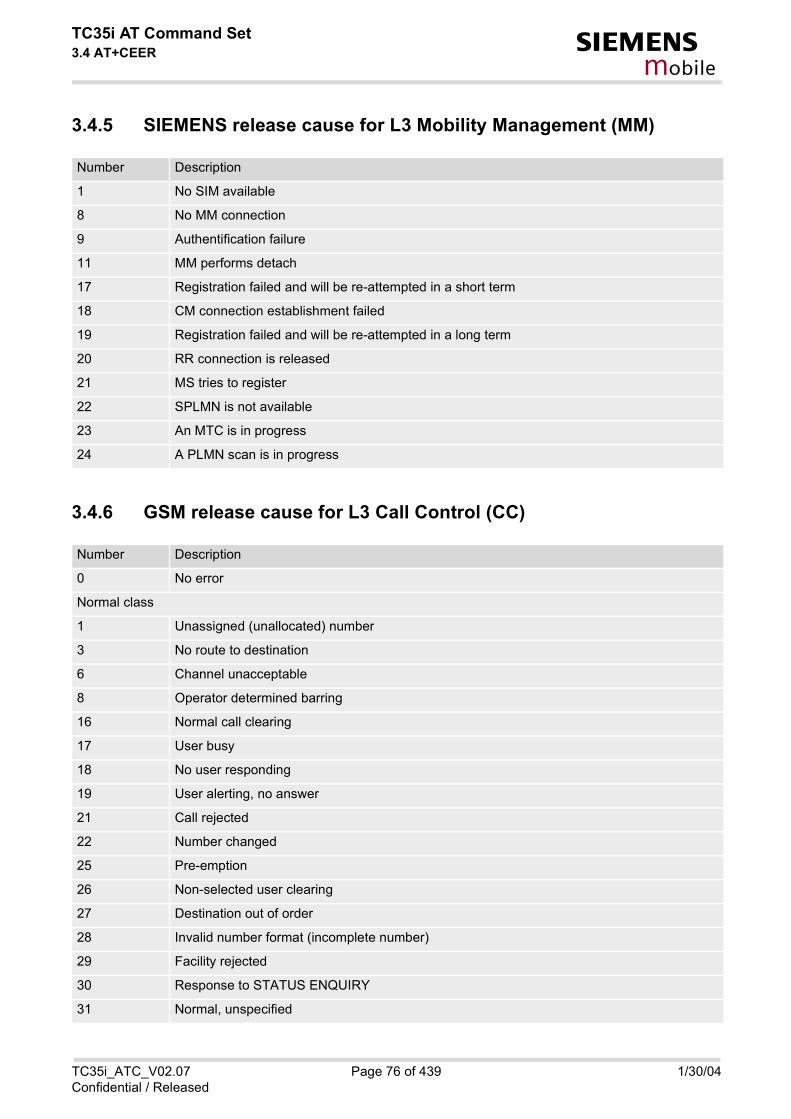
TC35i AT Command Set3.4 AT+CEER s
mobile
3.4.5 SIEMENS release cause for L3 Mobility Management (MM)
3.4.6 GSM release cause for L3 Call Control (CC)
Number Description
1 No SIM available
8 No MM connection
9 Authentification failure
11 MM performs detach
17 Registration failed and will be re-attempted in a short term
18 CM connection establishment failed
19 Registration failed and will be re-attempted in a long term
20 RR connection is released
21 MS tries to register
22 SPLMN is not available
23 An MTC is in progress
24 A PLMN scan is in progress
Number Description
0 No error
Normal class
1 Unassigned (unallocated) number
3 No route to destination
6 Channel unacceptable
8 Operator determined barring
16 Normal call clearing
17 User busy
18 No user responding
19 User alerting, no answer
21 Call rejected
22 Number changed
25 Pre-emption
26 Non-selected user clearing
27 Destination out of order
28 Invalid number format (incomplete number)
29 Facility rejected
30 Response to STATUS ENQUIRY
31 Normal, unspecified
TC35i_ATC_V02.07 Page 76 of 439 1/30/04Confidential / Released

TC35i AT Command Set3.4 AT+CEER s
mobile
Resource unavailable class
34 No circuit/channel available
38 Network out of order
41 Temporary failure
42 Switching equipment congestion
43 Access information discarded
44 Requested circuit/channel not available
47 Resource unavailable, unspecified
Service or option not available class
49 Quality of service unavailable
50 Requested facility not subscribed
55 Incoming calls barred within the CUG
57 Bearer capability not authorized
58 Bearer capability not presently available
63 Service or option not available, unspecified
Service or option not implemented
65 Bearer service not implemented
68 ACM equal or greater than ACMmax
69 Requested facility not implemented
70 Only restricted digital information bearer capability is available
79 service or option not implemented, unspecified
Invalid message (e.g. parameter out of range) class
81 Invalid transaction identifier value
87 User not member of CUG
88 Incompatible destination
91 Invalid transit network selection
95 Semantically incorrect message
Protocol error (e.g. unknown message) class
96 Invalid mandatory information
97 Message type non-existant or not implemented
98 Message type not comaptible with protocol state
99 Information element non-existent or not implemented
100 Conditional information element error
101 Message not compatible with protocol
102 Recovery on timer expiry
111 Protocol error, unspecified
Number Description
TC35i_ATC_V02.07 Page 77 of 439 1/30/04Confidential / Released

TC35i AT Command Set3.4 AT+CEER s
mobile
3.4.7 SIEMENS release cause for L3 Call Control (CC)
3.4.8 SIEMENS release cause for L3 Advice of Charge (AOC)
3.4.9 GSM Release cause for Supplementary Service Call
Interworking class
127 Interworking, unspecified
Number Description
1 Call dropped
2 Service not available
3 Hold procedure not available
4 Temporary no service, previous procedure not yet finished
5 No speech service available
6 Call reestablishment procedure active
7 Mobile received a release (complete) message during a modify procedure (modify reject)
8 Call clearing, because loss of radio connection, if no reestablishment is allowed (call not active)
10 Number not included in FDN list
Notifications
300 Called party barred incoming call
Number Description
1 SIM data not available
2 SIM does not support AOC
3 SIM data access error
4 ACM limit almost reached ACM range overflow
5 ACM range overflow
Number Description
0 No error (default)
1 UnknownSubscriber
9 IllegalSubscriber
10 BearerServiceNotProvisioned
11 TeleserviceNotProvisioned
12 IllegalEquipment
Number Description
TC35i_ATC_V02.07 Page 78 of 439 1/30/04Confidential / Released

TC35i AT Command Set3.4 AT+CEER s
mobile
13 CallBarred
15 CUGReject
16 IllegalSSOperation
17 SSErrorStatus
18 SSNotAvailable
19 SSSubscriptionViolation
20 SSIncompatibility
21 FacilityNotSupported
27 AbsentSubscriber
29 ShortTermDenial
30 LongTermDenial
34 SystemFailure
35 DataMissing
36 UnexpectedDataValue
37 PWRegistrationFailure
38 NegativePWCheck
43 NumberOfPWAttemptsViolation
71 UnknownAlphabet
72 USSDBusy
126 MaxNumsOfMPTYCallsExceeded
127 ResourcesNotAvailable
General Problem Codes
300 Unrecognized Component
301 Mistyped Component
302 Badly Structured Component
Invoke Problem Codes
303 Duplicate Invoke ID
304 Unrecognized Operation
305 Mistyped Parameter
306 Resource Limitation
307 Initiating Release
308 Unrecognized Linked ID
309 Linked Response Unexpected
310 Unexpected Linked Operation
Return Result Problem Codes
311 Unrecognize Invoke ID
312 Return Result Unexpected
Number Description
TC35i_ATC_V02.07 Page 79 of 439 1/30/04Confidential / Released

TC35i AT Command Set3.4 AT+CEER s
mobile
3.4.10 SIEMENS release cause for Call-related Supplementary Services (CRSS)
313 Mistyped Parameter
Return Error Problem Codes
314 Unrecognized Invoke ID
315 Return Error Unexpected
316 Unrecognized Error
317 Unexpected Error
318 Mistyped Parameter
Number Description
0 ECT procedure failed (timer expired)
1 Call has been cleared without receiving an answer to ECT request
2 Initial conditions not fulfilled (one active, one held call)
3 Received "return error"
4 Call has been cleared without receiving an answer to CCBS request
5 Initial conditions for CCBS not fulfilled (Idle CRSS)
Causes related to nature of request
25 LLC or SNDCP failure
26 Insufficient resources
27 Unknown or missing access point name
28 Unknown PDP address or PDP type
29 User authentification failed
30 Activation rejected by GGSN
31 Activation rejected, unspecified
32 Service option not supported
33 Requested service option not subscribed
34 Service option temporarily out of order
35 NSAPI already used
36 Regular PDP context deactivation
37 QoS not accepted
38 Network failure
39 Reactivation requested
40 Feature not supported
Causes related to invalid messages
81 Invalid transaction identifier value
Number Description
TC35i_ATC_V02.07 Page 80 of 439 1/30/04Confidential / Released

TC35i AT Command Set3.4 AT+CEER s
mobile
95 Semantically incorrect message
96 Invalid mandatory information
97 Message type non-existant or not implemented
98 Message type not comaptible with protocol state
99 Information element non-existent or not implemented
100 Conditional information element error
101 Message not compatible with protocol
111 Protocol error, unspecified
Number Description
TC35i_ATC_V02.07 Page 81 of 439 1/30/04Confidential / Released

TC35i AT Command Set3.5 ATS18 s
mobile
3.5 ATS18 Extended call release report
Syntax
Command Description
This command enables or disables the presentation of extended call release reports for fax and data calls. Thecall release report is presented in numeric format and includes the following parameters:
If enabled the message will be reported every time a fax or data call is released or fails to be established.
Parameter Description
An odd number enables the presentation of the extended call release report. An even number disables this fea-ture.
0(&F)...255
Location ID as number code (see also <locationID> of AT+CEER). Location IDs are listed in section 3.4.1.Each ID is related to another table that contains a list of <reason>s.
Reason for last call release as number code (see also <reason> of AT+CEER). <reason> numbers and theassociated descriptions are listed in several tables, sorted by different categories in Chapter AT+CEER. Thetables can be found proceeding from the Location IDs listed in 3.4.1.
Read Command
ATS18?
Response(s)
<n>OK
Write Command
ATS18=<n>
Response(s)
OK
PIN ASC0 MUX1 MUX2 MUX3
� � � � �
Reference(s)
V.25ter
+CAUSE: <locationID>, <reason>
<n>(num)(&W)(&V)
<locationID>(num)
<reason>(num)
TC35i_ATC_V02.07 Page 82 of 439 1/30/04Confidential / Released

TC35i AT Command Set3.5 ATS18 s
mobile
Note
• The command applies only to circuit switched data and fax calls. For voice calls extended call release reportscan be retrieved using the command AT+CEER.
Examples
EXAMPLE 1
EXAMPLE 2
ATS18=1 Enables the presentation of extended call release reports.OK
ATD03012345678 Now, a mobile originated data call fails.+CAUSE: 8:17 An extended error report is output, followed by the result code BUSY.BUSY The Location ID 8 stated in section 3.4.1 points to section 3.4.6, where
17 = "User busy".
ATS18=1 Enables the presentation of extended call release reports.OK
ATD03012345678 Now, a mobile originated data call is set up.CONNECT 9600/RLP
Hello,....
+++ Call ends after remote party hung up.+CAUSE: 8:16 Normal call release is reported, followed by the result code NO CAR-
RIER.NO CARRIER The Location ID 8 stated in section 3.4.1 points to section 3.4.6, where
16 = "Normal call clearing".
TC35i_ATC_V02.07 Page 83 of 439 1/30/04Confidential / Released

TC35i AT Command Set3.6 AT+CPAS s
mobile
3.6 AT+CPAS Mobile equipment activity status
Syntax
Command Description
TA returns the activity status of ME.
Parameter Description
0 ready
3 incoming call (ringing)
4 call in progress or call hold
Test Command
AT+CPAS=?
Response(s)
+CPAS: (list of supported<pas>s) OK
Exec Command
AT+CPAS
Response(s)
+CPAS: <pas>OKERROR+CME ERROR: <err>
PIN ASC0 MUX1 MUX2 MUX3
� � � � �
Reference(s)
GSM 07.07
<pas>(num)
TC35i_ATC_V02.07 Page 84 of 439 1/30/04Confidential / Released

TC35i AT Command Set3.7 AT+WS46 s
mobile
3.7 AT+WS46 Select wireless network
Syntax
Parameter Description
12 GSM digital cellular
Test Command
AT+WS46=?
Response(s)
+WS46: (list of supported<n>s) OK
Read Command
AT+WS46?
Response(s)
<n> OK
Write Command
AT+WS46=[<n>]
Response(s)
OK
PIN ASC0 MUX1 MUX2 MUX3
� � � � �
Reference(s)
GSM 07.07
<n>(num)
TC35i_ATC_V02.07 Page 85 of 439 1/30/04Confidential / Released

TC35i AT Command Set4. Serial Interface Control Commands s
mobile
4. Serial Interface Control Commands
The AT Commands described in this chapter allow the external application to determine various settings related to the TC35i's serial interface.
4.1 AT\Q Flowcontrol
Syntax
Parameter Description
[0](&F) disable flow control
1 XON/XOFF software flow control
2 only CTS by DCE
3 RTS/CTS hardware flow controlRecommended for the following procedures: incoming or outgoing data calls,fax calls, MUX mode.Often, the initialization routine of Fax programs includes enabling RTS/CTShandshake, eliminating the need to issue AT\Q3 once again.
Notes
• When using XON/XOFF flow control (AT\Q1) in online mode, +++ should not be used while the data trans-mission is paused with XOFF. Before entering the command mode with +++ the paused transmission shouldbe resumed using the XON character.
• For compatibility reasons, the AT\Q command can be used in Multiplex mode, though the settings will nottake effect. However, be aware that whenever you use the AT\Q write command in Multiplex mode and thensave the current configuration to the user profile with AT&W, the changed AT\Q setting will become active afterrestart.
• Flow control can also be set using AT+IFC.
Exec Command
AT\Q[<n>]
Response(s)
OK
PIN ASC0 MUX1 MUX2 MUX3
� � � � �
Reference(s)
V.25ter
<n>(num)(&W)(&V)
TC35i_ATC_V02.07 Page 86 of 439 1/30/04Confidential / Released

TC35i AT Command Set4.2 AT&C s
mobile
4.2 AT&C Set circuit Data Carrier Detect (DCD) function mode
Syntax
Command Description
This parameter determines how the state of circuit 109(DCD) relates to the detection of received line signal fromthe distant end.
Parameter Description
[0] DCD line is always ON
1(&F) DCD line is ON in the presence of data carrier only
Exec Command
AT&C[<value>]
Response(s)
OK
PIN ASC0 MUX1 MUX2 MUX3
� � � � �
Reference(s)
V.25ter
<value>(num)(&W)(&V)
TC35i_ATC_V02.07 Page 87 of 439 1/30/04Confidential / Released

TC35i AT Command Set4.3 AT&D s
mobile
4.3 AT&D Set circuit Data Terminal Ready (DTR) function mode
Syntax
Command Description
This parameter determines how the TA responds when circuit 108/2 (DTR) is changed from ON to OFF duringdata mode.
Parameter Description
[0] TA ignores status of DTR.
1 ON->OFF on DTR: Change to command mode while retaining the connectedcall.
2(&F) ON->OFF on DTR: Disconnect data call, change to command mode. Duringstate DTR = OFF is auto-answer off.
Exec Command
AT&D[<value>]
Response(s)
OK
PIN ASC0 MUX1 MUX2 MUX3
� � � � �
Reference(s)
V.25ter
<value>(num)(&W)(&V)
TC35i_ATC_V02.07 Page 88 of 439 1/30/04Confidential / Released

TC35i AT Command Set4.4 AT%D s
mobile
4.4 AT%D Automatic Dial on DTR Line Activation
Syntax
Command Description
Enable and disable automatic dialling on DTR line activation. A more generic way to control the TC35i via its DTR line is available with AT^SCFG, refer to parameter <AutoEx-ecATC>. If automatic dialling is enabled with AT%D and the DTR line switches from OFF to ON state, the ME attempts toset up an outgoing call to the number stored at the first index of the ''ME'' phone book, or using telephone number"112" in case of an emergency call. If enabled, DTR activation triggers a dial command (ATD) as though it were entered by a TE. Therefore if in thissituation characters are entered on the same serial channel the ongoing dial command will be terminated (userbreak).When a call setup starts all other active or held calls are dismissed.Repeated DTR activation events are ignored while call setup is in progress or during a call established by DTRactivation. Also all DTR activation events during multiplex mode are discarded.
Test Command
AT%D=?
Response(s)
%D:(list of supported <mode>s), (list of supported <dialType>s) OK
Read Command
AT%D?
Response(s)
%D: <mode>, <dialType> OK
Exec Command
AT%D[<mode>[, <dialType>]]
Response(s)
OK+CME ERROR: invalid characters in text stringInvalid parameter. +CME ERROR: operation not supportedNo physical DTR signal line is supported for the serial channel or no access to the CSD transmission unit is supported for the serial channel but a data call is requested (i.e. no ";" is appended, see below). However, data calls are applicable on serial channel 0 only. +CME ERROR: operation temporary not allowedCommand is not supported during multiplex mode (AT+CMUX).
PIN ASC0 MUX1 MUX2 MUX3
� � � � �
TC35i_ATC_V02.07 Page 89 of 439 1/30/04Confidential / Released

TC35i AT Command Set4.4 AT%D s
mobile
To enable auto dialling for data and voice calls after ME's power on it is necessary to disable PIN authorizationwith the command AT+CLCK="SC",0,<password>. To prevent misuse of this unprotected SIM card it is recom-mended to limit its network facilities. For details refer to the "FD" parameter of AT+CLCK.
If dialling starts on DTR line activation, possible responses are as though the dial command were entered by aTE, for instance: • OK
If successfully connected and voice call • CONNECT<text>
If successfully connected and non-voice call. <text> is sent out if parameter setting is ATX>0. TA switches todata state.
• +CME ERROR: SIM not inserted SIM card is needed to set up data and voice calls.
• +CME ERROR: SIM PIN required PIN is required to set up data and voice calls.
• +CME ERROR: not found Phone book entry is required for data and voice calls, but no telephone number is provided.
• NO DIALTONE If there is no dialtone and parameter setting ATX2 or ATX4.
• BUSY If busy and parameter setting ATX3 or ATX4.
• NO CARRIER If a connection cannot be set up or call is finished by other party.
Parameter Description
Auto dial state on DTR activation (OFF-ON transition). Additional functionality is available with AT^SCFG, e.g. sending a short message (SMS) on DTR activation canbe done with parameter <AutoExecATC> set to "AT+CMSS=1".
[0](&F) Disable functionality.
1 Enable dialling of the telephone number located at index "1" in the "ME" phonebook. If <dialType> is "!" an emergency call is set up. Refer to AT+CPBS andAT+CPBW.
Determine type of performed dial.
[““](&F) If omitted performed dial command leads to a data call.
“;“ Performed dial command leads to a voice call.
“!“ Dial command leads to an emergency call, i.e. ATD "112"; is performed. NoSIM card needs to be inserted in this case.CAUTION!AT%D1! setting especially in conjunction with AT&W can easily lead to erroneousemergency call setups.
Notes
• To suppress arbitrary call releases on DTR deactivation setting of AT&D0 is strongly recommended.
• If several AT commands are entered on the same line AT%D needs to be the last one.
<mode>(num)(&W)
<dialType>(str)(&W)
TC35i_ATC_V02.07 Page 90 of 439 1/30/04Confidential / Released

TC35i AT Command Set4.4 AT%D s
mobile
• Command settings are storable via AT&W.
• Exec command is not supported during multiplex mode (AT+CMUX).
Example
Setup the first entry in the ME phone book and enable automatic dial on DTR line activation.For details regarding phone book handling refer to AT+CPBS and AT+CPBW.
If a DTR line activation has occured:
AT+CPBS="ME" Select ME phone bookOK
AT+CPBW=1,"+498972255000",145,"Customer Sup-port"
Store number of Siemens AG Wireless Modules Customer Support Hotline to tell that everything works as expected.
OK
AT%D1; Enable automatic dial.OK
AT&W Store setting in the user profile.OK
OK ATD command entry confirmation.NO CARRIER Called party hang up.
TC35i_ATC_V02.07 Page 91 of 439 1/30/04Confidential / Released

TC35i AT Command Set4.5 AT&S s
mobile
4.5 AT&S Set circuit Data Set Ready (DSR) function mode
Syntax
Command Description
This parameter determines how the TA sets circuit 107 (DSR) depending on the communication state of the TAinterfacing TE.
Parameter Description
[0](&F) DSR line is always ON
1 TA in command mode: DSR is OFF.TA in data mode: DSR is ON.
Exec Command
AT&S[<value>]
Response(s)
OK
PIN ASC0 MUX1 MUX2 MUX3
� � � � �
Reference(s)
V.25ter
<value>(num)(&W)(&V)
TC35i_ATC_V02.07 Page 92 of 439 1/30/04Confidential / Released

TC35i AT Command Set4.6 ATE s
mobile
4.6 ATE Enable command echo
Syntax
Command Description
This setting determines whether or not the TA echoes characters received from TE during command state.
Parameter Description
[0] Echo mode off
1(&F) Echo mode on
Note
• In case of using the command without parameter, <value> is set to 0.
Exec Command
ATE[<value>]
Response(s)
OK
PIN ASC0 MUX1 MUX2 MUX3
� � � � �
Reference(s)
V.25ter
<value>(num)(&W)(&V)
TC35i_ATC_V02.07 Page 93 of 439 1/30/04Confidential / Released

TC35i AT Command Set4.7 AT+ICF s
mobile
4.7 AT+ICF Serial Interface Character Framing
The command AT+ICF can be used to set or query the character framing.
Syntax
Command Description
The test command returns the values of the supported character framings.
The read command returns the currently selected character framing.
The write command determines the serial interface character framing format and parity used for receiving andtransmitting.
Parameter Description
Specifies the character format used for receiving and transmitting.
1 8 data 0 parity 2 stop
Test Command
AT+ICF=?
Response(s)
+ICF: (list of supported <format>s), (list of supported <parity>s) OK
Read Command
AT+ICF?
Response(s)
+ICF: <format>[, <parity>] OK
Write Command
AT+ICF=[<format>][, <parity>]
Response(s)
OKERROR
PIN ASC0 MUX1 MUX2 MUX3
� � � � �
Reference(s)
V.25ter
<format>(num)(&W)(&V)
TC35i_ATC_V02.07 Page 94 of 439 1/30/04Confidential / Released
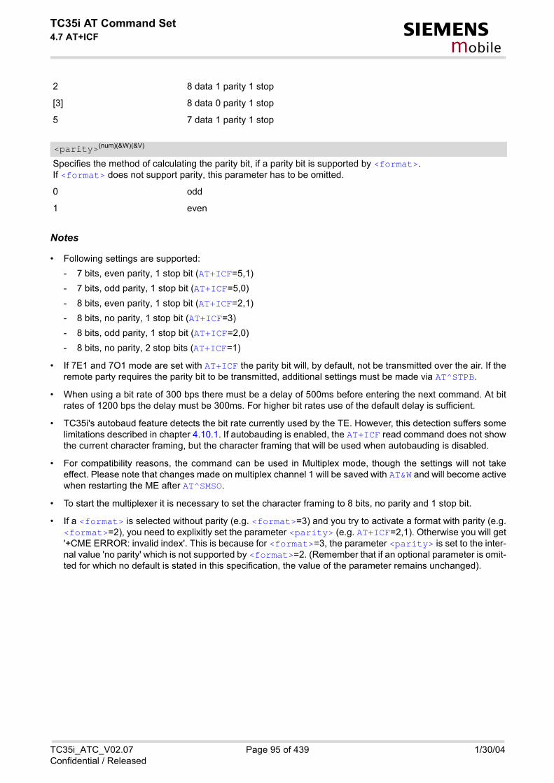
TC35i AT Command Set4.7 AT+ICF s
mobile
2 8 data 1 parity 1 stop
[3] 8 data 0 parity 1 stop
5 7 data 1 parity 1 stop
Specifies the method of calculating the parity bit, if a parity bit is supported by <format>.If <format> does not support parity, this parameter has to be omitted.
0 odd
1 even
Notes
• Following settings are supported: - 7 bits, even parity, 1 stop bit (AT+ICF=5,1) - 7 bits, odd parity, 1 stop bit (AT+ICF=5,0) - 8 bits, even parity, 1 stop bit (AT+ICF=2,1) - 8 bits, no parity, 1 stop bit (AT+ICF=3) - 8 bits, odd parity, 1 stop bit (AT+ICF=2,0) - 8 bits, no parity, 2 stop bits (AT+ICF=1)
• If 7E1 and 7O1 mode are set with AT+ICF the parity bit will, by default, not be transmitted over the air. If theremote party requires the parity bit to be transmitted, additional settings must be made via AT^STPB.
• When using a bit rate of 300 bps there must be a delay of 500ms before entering the next command. At bitrates of 1200 bps the delay must be 300ms. For higher bit rates use of the default delay is sufficient.
• TC35i's autobaud feature detects the bit rate currently used by the TE. However, this detection suffers somelimitations described in chapter 4.10.1. If autobauding is enabled, the AT+ICF read command does not showthe current character framing, but the character framing that will be used when autobauding is disabled.
• For compatibility reasons, the command can be used in Multiplex mode, though the settings will not takeeffect. Please note that changes made on multiplex channel 1 will be saved with AT&W and will become activewhen restarting the ME after AT^SMSO.
• To start the multiplexer it is necessary to set the character framing to 8 bits, no parity and 1 stop bit.
• If a <format> is selected without parity (e.g. <format>=3) and you try to activate a format with parity (e.g.<format>=2), you need to explixitly set the parameter <parity> (e.g. AT+ICF=2,1). Otherwise you will get'+CME ERROR: invalid index'. This is because for <format>=3, the parameter <parity> is set to the inter-nal value 'no parity' which is not supported by <format>=2. (Remember that if an optional parameter is omit-ted for which no default is stated in this specification, the value of the parameter remains unchanged).
<parity>(num)(&W)(&V)
TC35i_ATC_V02.07 Page 95 of 439 1/30/04Confidential / Released

TC35i AT Command Set4.8 AT+IFC s
mobile
4.8 AT+IFC Set Flow Control separately for data directions
The command AT+IFC can be used to set or query the data flow control separately for each data direction.
Syntax
Command Description
The test command returns the values of the supported methods of flow control.
The read command returns the currently selected methods of flow control.
The write command determines the data flow control on the serial interface.
Parameter Description
Specifies the method used by the TE when receiving data from the TA.
[0] none
Test Command
AT+IFC=?
Response(s)
+IFC: (list of supported <TEflowcontrol>s), (list of supported <TAflowcontrol>s) OK
Read Command
AT+IFC?
Response(s)
+IFC: <TEflowcontrol>, <TAflowcontrol> OK
Write Command
AT+IFC=<TEflowcontrol>, <TAflowcontrol>
Response(s)
OKERROR
PIN ASC0 MUX1 MUX2 MUX3
� � � � �
Reference(s)
V.25ter
<TEflowcontrol>(num)(&W)
TC35i_ATC_V02.07 Page 96 of 439 1/30/04Confidential / Released

TC35i AT Command Set4.8 AT+IFC s
mobile
1 XON/XOFF, terminate flow control in the Cellular Engine
2 RTS line
3 XON/XOFF, evaluate flow control in the Cellular Engine and pass it through(over the air) to the opposite TE
Specifies the method used by the TA when receiving data from the TE.
[0] none
1 XON/XOFF
2 CTS line
Notes
• Flow control settings made with AT\Q are valid in both data directions.
• When using XON/XOFF flow control ( AT+IFC =1,x or AT+IFC =3,x) in data mode, +++ should not be usedwhile the data transmission is paused with XOFF. Before entering the command mode with +++ the pausedtransmission should be resumed using the XON character.
• For compatibility reasons, the AT+IFC command can be used in Multiplex mode, though the settings will nottake effect. However, be aware that whenever you use the AT+IFC write command in Multiplex mode andthen save the current configuration to the user profile with AT&W, the changed AT+IFC setting will becomeactive after restart.
<TAflowcontrol>(num)(&W)
TC35i_ATC_V02.07 Page 97 of 439 1/30/04Confidential / Released

TC35i AT Command Set4.9 AT+ILRR s
mobile
4.9 AT+ILRR Set TE-TA local rate reporting
The command AT+ILRR controls whether or not the intermediate result code "+ILRR" is transmitted from theDCE to the DTE.
Syntax
Intermediate Result Code
+ILRR: <rate>
Indicates port rate setting on connection.
Command Description
The write command determines whether or not an intermediate result code of local rate is reported at connectionsetup. The rate is reported before the final result code of the connection is transmitted to the TE.
Test Command
AT+ILRR=?
Response(s)
+ILRR: (list of supported <value>s) OK
Read Command
AT+ILRR?
Response(s)
+ILRR: <value> OK
Write Command
AT+ILRR=<value>
Response(s)
OKERROR+CME ERROR
PIN ASC0 MUX1 MUX2 MUX3
� � � � �
Reference(s)
V.25ter
TC35i_ATC_V02.07 Page 98 of 439 1/30/04Confidential / Released

TC35i AT Command Set4.9 AT+ILRR s
mobile
Parameter Description
0(&F) Disables reporting of local port rate
1 Enables reporting of local port rate
port rate setting on connection (bps)
0 Autobauding (see chapter 4.10.1)
300
600
1200
2400
4800
9600
14400
19200
28800
38400
57600
115200
230400 (cannot be used in terminal version)
<value>(num)(&W)(&V)
<rate>(num)
TC35i_ATC_V02.07 Page 99 of 439 1/30/04Confidential / Released

TC35i AT Command Set4.10 AT+IPR s
mobile
4.10 AT+IPR Set fixed local rate
The command AT+IPR can be used to set or query the DTE-DCE interface bit rate.
Syntax
Command Description
The test command returns the values of the supported automatically detectable bit rates and the values of thesupported fixed bit rates.
The read command returns the current bit rate of the interface.
The write command specifies the bit rate to be used for the interface. When you set a fixed-rate, make sure thatboth DTE (TE) and DCE (TA) are configured to the same rate. When you select autobauding, the DCE will auto-matically recognize the bit rate currently used by the DTE. The setting is stored in the non-volatile memory and will be used whenever the engine is powered up again. How-ever, in case of autobaud mode (AT+IPR=0) the detected DCE bit rate will not be saved and, therefore, needsto be resynchronized after restarting the GSM engine (see chapter 4.10.1).
Test Command
AT+IPR=?
Response(s)
+IPR: (list of supported auto-detectable <rate>s) , (list of supported fixed-only <rate>s) OK
Read Command
AT+IPR?
Response(s)
+IPR: <rate> OK
Write Command
AT+IPR=<rate>
Response(s)
OKERROR+CME ERROR
PIN ASC0 MUX1 MUX2 MUX3
� � � � �
Reference(s)
V.25ter
TC35i_ATC_V02.07 Page 100 of 439 1/30/04Confidential / Released

TC35i AT Command Set4.10 AT+IPR s
mobile
While multiplex mode write command is not supported.
Parameter Description
bit rate per second (bps)
0(D) Activate autobauding (see chapter 4.10.1).
300
600
1200
2400
4800
9600
14400
19200
28800
38400
57600
115200
230400 (not available with terminal version of TC35i)
Notes
• The factory default is autobauding enabled (AT+IPR=0). It will not be restored with AT&F.
• The current setting of AT+IPR will be preserved when you download new firmware (i.e. a firmware updatedoes not restore the factory setting) or in the event of power failure.
• Generally, AT+IPR should be used as a standalone command. If combinations with other commands on thesame command line cannot be avoided, the following constraints shall be considered: - Avoid combinations with the AT commands listed in chapter 1.4.2.- Take into account, that a delay of 100ms is required between the response to the last command (e.g. OK)
and the next command on the same line.- When you enter AT+IPR=0, autobauding will be activated after the response to the last command is
received.- When local echo is active (ATE1) and you enter AT+IPR=x with other commands you may encounter the
following problem: if switching to the new bit rate takes effect while a response is being transmitted, thelast bytes may be sent with the new bit rate and thus, not properly transmitted. The following commandswill be correctly sent at the new bit rate.
• In order to account for greater amounts of data it is recommended to choose a minimum bit rate of 2400 bps.If the ME is operated in Multiplex mode we suggest a minimum bit rate of 4800bps.
• A selected bit rate takes effect after the write commands returns OK (except for Multiplex mode).
• In Multiplex mode, the write command AT+IPR=<rate> will not change bit rate currently used, but the newbit rate will be stored and becomes active, when the module is restarted.
• AT+IPR=230400 cannot be used with the terminal version. Autobauding with 230400 bps is available but notrecommended.
<rate>(num)(&V)
TC35i_ATC_V02.07 Page 101 of 439 1/30/04Confidential / Released

TC35i AT Command Set4.10 AT+IPR s
mobile
4.10.1 AutobaudingTo take advantage of autobaud mode specific attention must be paid to the following requirements:
• Synchronization between DTE and DCEEnsure that DTE and DCE are correctly synchronized and the bit rate used by the DTE is detected by theDCE (ME). To allow the bit rate to be synchronized simply use an "AT" or "at" string. This is necessary - after you have activated autobauding- when you start up the GSM engine while autobauding is enabled. It is recommended to wait 3 to 5 seconds
before sending the first AT character. Otherwise undefined characters might be returned.If you want to use autobauding and autoanswer at the same time, you can easily enable the DTE-DCE syn-chronization, when you activate autobauding first and then configure the autoanswer mode (ATS0 � 0).
• Restrictions on autobauding operation- The serial interface shall be used with 8 data bits, no parity and 1 stop bit (factory setting), e.g. 2 stop bits
are not supported for autobaud mode. - A/ cannot be used.- Only the strings "AT" or "at" can be detected (neither "At" nor "aT").- URCs that may be issued before the ME detects a new bit rate (by receiving the first AT character) will be
sent at the previously detected bit rate or, after ME restart, at 57600 bps.- It is not recommended to switch to autobauding from a bit rate that cannot be detected by the the autobaud
mechanism (e.g. 300 bps). Responses to AT+IPR=0 and any commands on the same line might be cor-rupted.
- If entering several AT commands on the same line, consider the requirements described above.- When autobauding is switched on:
+ only data length, parity and baud rate are automatically detected + if using 1 stop bit, AT+ICF=1 should not be used, because it uses 2 stop bits + if using 2 stop bits, no combination of AT+ICF should be used, which uses 1 stop bit
- Terminal version of TC35i shall not use autobauding with baudrates above 115200bps.• Autobauding and bit rate after restart
The most recently detected bit rate is stored when the ME is powered down (with AT^SMSO). Therefore, eachtime the module is restarted the correct bit rate must be found as described above. Unless the bit rate is deter-mined, the following constraints apply: - An incoming CSD call cannot be accepted. This must be taken into account when autobauding and
autoanswer mode (ATS0 � 0) are enabled at the same time, escpecially if SIM PIN 1 authentication is doneautomatically and the setting ATS0 � 0 is stored to the user profile with AT&W.
- Until the bit rate is found, URCs generated after restart will be output at 57600 bps. This applies only touser defined URCs, such as "+CREG", "CCWA", "^SCKS" etc. The URCs "^SYSSTART", "^SYSSTARTALARM MODE" and "^SYSSTART CHARGE-ONLY MODE" will not be indicated when autobauding isenabled.
Note: To avoid any problems caused by undetermined bit rates in the direction from DCE to DTE we stronglyrecommend to configure a fixed bit rate rather than autobauding.
• Autobauding and multiplex modeWhile TC35i is using autobauding its serial interface can't be switched to multiplex mode via AT+CMUX. If mul-tiplex mode is already enabled neither autobauding nor any fixed baudrate can be selected with AT+IPR.
TC35i_ATC_V02.07 Page 102 of 439 1/30/04Confidential / Released

TC35i AT Command Set4.11 AT+CMUX s
mobile
4.11 AT+CMUX Enter multiplex mode
Syntax
Command Description
Multiplex mode according to the ETSI TS 101 669 and GSM 07.10 enables one physical serial asynchronousinterface to be partitioned into three virtual channels. This allows you to take advantage of up to 3 simultaneoussessions running on the serial interface. For example, you can send or receive data or make a call on the firstchannel, while the other two channels are free to control the module with AT commands.The TC35i module incorporates an internal multiplexer and thus integrates all the functions needed to implementfull-featured multiplex solutions. For the application on top, customers have the flexibility to create their own mul-tiplex programs conforming to the multiplexer protocol. To help system integrators save the time and expense ofdesigning multiplexer applications, SIEMENS AG offers WinMUX2k, a ready-to-use multiplex driver for Windows2000 and Windows XP. Another approach is to develop customized solutions based on the sources of theWinMux2k driver.Refer to [4] which provides a detailed description of the multiplex architecture and step-by-step instructions ofhow to install and configure the multiplex mode. The WinMUX2k driver and its source files can be supplied on
Test Command
AT+CMUX=?
Response(s)
+CMUX: (list of supported<mode>s) OK
Read Command
AT+CMUX?
Response(s)
+CMUX: <mode> OKERROR+CME ERROR: <err>
Write Command
AT+CMUX=<mode>
Response(s)
OKERROR+CME ERROR: <err>
PIN ASC0 MUX1 MUX2 MUX3
� � � � �
Reference(s)
GSM 07.07, GSM 07.10
TC35i_ATC_V02.07 Page 103 of 439 1/30/04Confidential / Released

TC35i AT Command Set4.11 AT+CMUX s
mobile
request. Please contact your local distributor to obtain the latest installation software and user's guide.
Parameter Description
Multiplexer transparency mechanism
0 Basic option
Subparameters defined in GSM07.07 are adjusted for control and logical channels as follows
0 UIH frames used only (control channel)
Notes
• The write command is used to enter the multiplex mode. The setup of the logical channels is initiated by theTE, i.e. the TE acts as initiator. This means that the TE shall ensure that logical channels are establishedbefore any further actions on the channels can be started.
• There is a timeout of five seconds, if the multiplexer protocol is enabled and no multiplexer control channel isestablished. The GSM engine returns to AT command mode.
• The parameter maximum frame size (N1) of AT+CMUX in GSM07.10 is fixed to 97 and cannot be changed.All other parameters are not available.
• Multiplexer mode requires character framing to be set to 8 bits, no parity and 1 stop bit. The setting can bemade using (AT+ICF=3).
4.11.1 Restrictions on Multiplex modeIn multiplex mode, CSD and fax calls can only be set up on logical channel 1. Due to this restriction, AT com-mands have a different behavior on channels 2+3 compared to channel 1. Several commands are not available,others return different responses. This chapter summarizes the concerned commands. For general rules andrestrictions to be considered in Multiplex mode please refer to [4].
Table 4.1: Availability of AT Commands on Virtual Channels
<mode>(num)
<subset>(num)
Command Behavior on channel 1 Behavior on channel 2+3
+++ not usable, but see note 2) not usable, but see note 2)
AT+CBST as described not usable
AT+CRLP as described not usable
AT+F... (Fax commands) as described not usable
AT&S as described not usable
ATA as described no Data Calls
ATD as described no Data Calls
ATDI as described not usable
ATL as described not usable
ATM as described not usable
ATO as described not usable
TC35i_ATC_V02.07 Page 104 of 439 1/30/04Confidential / Released

TC35i AT Command Set4.11 AT+CMUX s
mobile
1) Siemens GSM engines support the registers S0 - S29. You can change S0,S3,S4,S5,S6,S7,S8,S10 and S18 using therelated ATSn commands (see starting from ATS0). The other registers are read-only and for internal use only!
2) The applicability of the +++ escape sequence depends on the customer's external application based on the MulitplexerProtocol. Recommendations for implementing an appropriate modem status command (MSC) are provided in [4], Chapter"Escape Sequence".
Table 4.2: Summary of AT commands with Different Behavior in Multiplex Mode
ATS6 1) as described not usable
ATS7 1) as described not usable
ATS8 1) as described not usable
ATS10 1) as described not usable
ATS18 1) as described not usable
AT\V as described not usable
Command Description
AT\Q It is recommended to use hardware flow control (AT\Q3). XON/XOFF flow control (AT\Q1) is not supported in Multiplex mode.See note regarding AT\Qn settings stored with AT&W if Multiplex mode is active.
AT&V Different default configurations on channels 1, 2 and 3.
AT&W Different user profiles can be stored on each channel.
AT+IPR Before you start Multiplex mode, it is recommended to set the ME to 57600 bps (minimum should be 4800 bps). In Multiplex mode, the write command AT+IPR=<rate> cannot be used.
AT+IPR=0 Multiplex mode cannot be activated while autobauding is enabled.
AT+CALA On each channel an individual <text> message can be stored. but only one time setting applies to all channels. This means an alarm <time> set on one of the channels overwrites the time setting on all remaining channels. Therefore, the total number of alarm events returned by the read command AT+CALA? will always be <n>=0, no matter whether individual text messages are stored.When the alarm is timed out and executed the ME sends the URC only on the channel where the most recent alarm setting was made. The alarm time will be reset to "00/01/01,00:00:00" on all channels.
AT+CMEE Presentation mode can be separately configured for each channel.
AT+CNMA If Multiplex mode is activated the +CNMI parameter will be set to zero on all chan-nels, if one channel fails to acknowledge an incoming message within the required time.
AT+CNMI Phase 2+ parameters can only be used on one channel. The parameter for <mt> and <ds> on the other channels have to be set to zero. If either a SM or a Status Report is not acknowledged, all +CNMI parameter will be set to zero on all chan-nels.
AT+CFUN If the ME is in Multiplexer mode, it is not recommended to activate SLEEP mode with AT+CFUN=<fun>. The best approach to properly control SLEEP mode in this case is to issue the PSC messages described in [4], chapter "Power saving control (PSC)".
Command Behavior on channel 1 Behavior on channel 2+3
TC35i_ATC_V02.07 Page 105 of 439 1/30/04Confidential / Released

TC35i AT Command Set4.11 AT+CMUX s
mobile
AT+CPMS Parameter <mem3> will be the same on all instances, but the settings of <mem1> and <mem2> may vary on each instance.
AT^SSDA If one instance is set to <da>=1 and <mt>=1, then all other instances must be con-figured for <mt>=0.
Command Description
TC35i_ATC_V02.07 Page 106 of 439 1/30/04Confidential / Released
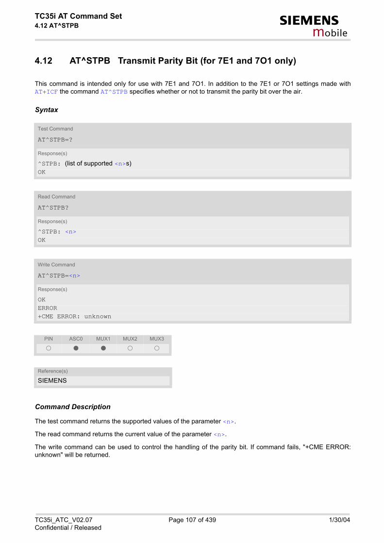
TC35i AT Command Set4.12 AT^STPB s
mobile
4.12 AT^STPB Transmit Parity Bit (for 7E1 and 7O1 only)
This command is intended only for use with 7E1 and 7O1. In addition to the 7E1 or 7O1 settings made withAT+ICF the command AT^STPB specifies whether or not to transmit the parity bit over the air.
Syntax
Command Description
The test command returns the supported values of the parameter <n>.
The read command returns the current value of the parameter <n>.
The write command can be used to control the handling of the parity bit. If command fails, "+CME ERROR:unknown" will be returned.
Test Command
AT^STPB=?
Response(s)
^STPB: (list of supported <n>s) OK
Read Command
AT^STPB?
Response(s)
^STPB: <n> OK
Write Command
AT^STPB=<n>
Response(s)
OKERROR+CME ERROR: unknown
PIN ASC0 MUX1 MUX2 MUX3
� � � � �
Reference(s)
SIEMENS
TC35i_ATC_V02.07 Page 107 of 439 1/30/04Confidential / Released

TC35i AT Command Set4.12 AT^STPB s
mobile
Parameter Description
0(&F) The parity bit will not be transmitted over the air and will be replaced with 0.This mode is the default setting if 7E1 or 7O1 is activated with AT+ICF.
1 In a data connection 8 bits will be transmitted, including the parity bit, i.e. theparity bit will be properly transmitted over the air. The setting shall be used ifproblems are encountered when TC35i is running in the default 7E1 or 7O1mode enabled with AT+ICF. In this case, AT^STPB=1 shall be set in additionto the 7E1 or 7O1 settings selected with AT+ICF.
<n>(num)(&W)
TC35i_ATC_V02.07 Page 108 of 439 1/30/04Confidential / Released

TC35i AT Command Set5. Security Commands s
mobile
5. Security Commands
The AT Commands described in this chapter allow the external application to determine various security related settings.
5.1 AT+CPIN Enter PIN
Syntax
Command Description
The read command returns an alphanumeric string indicating whether or not a password is required.
The write command lets the ME store the entered password. This may be for example the SIM PIN1 to registerto the GSM network, or the SIM PUK1 to replace a disabled PIN with a new one, or the PH-SIM PIN if the clienthas taken precautions for preventing damage in the event of loss or theft etc. See above for the list of passwords.
Test Command
AT+CPIN=?
Response(s)
OK
Read Command
AT+CPIN?
Response(s)
+CPIN: <code> OKERROR+CME ERROR: <err>
Write Command
AT+CPIN=<pin>[, <new pin>]
Response(s)
OKERROR+CME ERROR: <err>
PIN ASC0 MUX1 MUX2 MUX3
� � � � �
Reference(s)
GSM 07.07
TC35i_ATC_V02.07 Page 109 of 439 1/30/04Confidential / Released
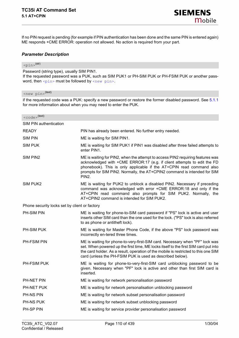
TC35i AT Command Set5.1 AT+CPIN s
mobile
If no PIN request is pending (for example if PIN authentication has been done and the same PIN is entered again)ME responds +CME ERROR: operation not allowed. No action is required from your part.
Parameter Description
Password (string type), usually SIM PIN1.If the requested password was a PUK, such as SIM PUK1 or PH-SIM PUK or PH-FSIM PUK or another pass-word, then <pin> must be followed by <new pin>.
if the requested code was a PUK: specify a new password or restore the former disabled password. See 5.1.1for more information about when you may need to enter the PUK.
SIM PIN authentication
READY PIN has already been entered. No further entry needed.
SIM PIN ME is waiting for SIM PIN1.
SIM PUK ME is waiting for SIM PUK1 if PIN1 was disabled after three failed attempts toenter PIN1.
SIM PIN2 ME is waiting for PIN2, when the attempt to access PIN2 requiring features wasacknowledged with +CME ERROR:17 (e.g. if client attempts to edit the FDphonebook). This is only applicable if the AT+CPIN read command alsoprompts for SIM PIN2. Normally, the AT+CPIN2 command is intended for SIMPIN2.
SIM PUK2 ME is waiting for PUK2 to unblock a disabled PIN2. Necessary if precedingcommand was acknowledged with error +CME ERROR:18 and only if theAT+CPIN read command also prompts for SIM PUK2. Normally, theAT+CPIN2 command is intended for SIM PUK2.
Phone security locks set by client or factory
PH-SIM PIN ME is waiting for phone-to-SIM card password if "PS" lock is active and userinserts other SIM card than the one used for the lock. ("PS" lock is also referredto as phone or antitheft lock).
PH-SIM PUK ME is waiting for Master Phone Code, if the above "PS" lock password wasincorrectly en-tered three times.
PH-FSIM PIN ME is waiting for phone-to-very-first-SIM card. Necessary when "PF" lock wasset. When powered up the first time, ME locks itself to the first SIM card put intothe card holder. As a result, operation of the mobile is restricted to this one SIMcard (unless the PH-FSIM PUK is used as described below).
PH-FSIM PUK ME is waiting for phone-to-very-first-SIM card unblocking password to begiven. Necessary when "PF" lock is active and other than first SIM card isinserted.
PH-NET PIN ME is waiting for network personalisation password
PH-NET PUK ME is waiting for network personalisation unblocking password
PH-NS PIN ME is waiting for network subset personalisation password
PH-NS PUK ME is waiting for network subset unblocking password
PH-SP PIN ME is waiting for service provider personalisation password
<pin>(str)
<new pin>(text)
<code>(text)
TC35i_ATC_V02.07 Page 110 of 439 1/30/04Confidential / Released

TC35i AT Command Set5.1 AT+CPIN s
mobile
PH-SP PUK ME is waiting for service provider personalisation unblocking password
PH-C PIN ME is waiting for corporate personalisation password
PH-C PUK ME is waiting for corprorate personalisation un-blocking password
Notes
• Caution: After entering a password with AT+CPIN all other commands that need access to data on the SIMcard may be blocked for up to 20 seconds!
• Successful PIN authentication only confirms that the entered PIN was recognized and correct. The output ofthe result code OK does not necessarily imply that the mobile is registered to the desired network.Typical example: PIN was entered and accepted with OK, but the ME fails to register to the network. This maydue to missing network coverage, denied network access with currently used SIM card, no valid roamingagreement between home network and currently available operators etc.ME offers various options to verify the present status of network registration: For example, the AT+COPS com-mand indicates the currently used network. With AT+CREG you can also check the current status and activatean unsolicited result code which appears whenever the status of the network registration changes (e.g. whenthe ME is powered up, or when the network cell changes).
• Wait 10 seconds after PIN input before using SMS related commands.
• <pin> and <new pin> can also be entered in quotation marks (e.g. "1234").
• To check the number of remaining attempts to enter the passwords use the AT^SPIC command.
• See AT+CPWD and AT^SPWD for information on passwords.
• See AT+CLCK and AT^SLCK for information on lock types.
5.1.1 What to do if PIN or password authentication fails?PIN1 / PUK1:After three failures to enter PIN 1, the SIM card is blocked (except for emergency calls). +CME ERROR: 12 willprompt the client to unblock the SIM card by entering the associated PUK (= PIN Unblocking Key / PersonalUnblocking Key). After ten failed attempts to enter the PUK, the SIM card will be invalidated and no longer oper-able. In such a case, the card needs to be replaced. PIN1 consists of 4 to 8 digits, PUK1 is an 8-digit code only.To unblock a disabled PIN1 you have two options:
• You can enter AT+CPIN=PUK1,new PIN1.• You can use the ATD command followed by the GSM code **05*PUK*newPIN*newPIN#;.
PIN2 / PUK2: PIN2 prevents unauthorized access to the features listed in AT+CPIN2. The handling of PIN2 varies with the pro-vider. PIN2 may either be a specific code supplied along with an associated PUK2, or a default code such as0000. In either case, the client is advised to replace it with an individual code. Incorrect input of PUK2 will per-manently block the additional features subject to PIN2 authentification, but usually has no effect on PIN1. PIN2consists of 4 digits, PUK2 is an 8-digit code only.To unblock a disabled PIN2 you have two options:
• You can enter AT+CPIN2=PUK2,new PIN2.• You can use the ATD command followed by the GSM code **052*PUK2*newPIN2*newPIN2#;.
Phone lock: If the mobile was locked to a specific SIM card (= "PS" lock or phone lock), the PUK that came with the SIM cardcannot be used to remove the lock. After three failed attempts to enter the correct password, ME returns +CPIN:PH-SIM PUK (= response to read command AT+CPIN?), i.e. it is now waiting for the Master Phone Code. This
TC35i_ATC_V02.07 Page 111 of 439 1/30/04Confidential / Released

TC35i AT Command Set5.1 AT+CPIN s
mobile
is an 8-digit device code associated to the IMEI number of the mobile which can only by obtained from the man-ufacturer or provider. When needed, contact Siemens AG and request the Master Phone Code of the specificmodule.There are two ways to enter the Master Phone code:
• You can enter AT+CPIN=Master Phone Code,new password.• You can use the ATD command followed by the GSM code *#0003*Master Phone Code#;.
Usually, the Master Phone Code will be supplied by mail or e-mail. If the received number is enclosed in the *#codes typically used for the ATD option, it is important to crop the preceding *#0003* characters and theappended #. Example: You may be given the string *#0003*12345678#. When prompted for the PH-SIM PUK simply enter12345678.If incorrectly input, the Master Phone Code is governed by a specific timing algorithm: (n-1)*256 seconds (seetable below). The timing should be considered by system integrators when designing an individual MMI.
SIM locks: These are factory set locks, such as "PF", "PN", "PU", "PP", "PC". An 8-digit unlocking code is required to operatethe mobile with a different SIM card, or to lift the lock. The code can only be obtained from the provider.Failure to enter the password is subject to the same timing algorithm as the Master Phone Code (see Tableabove).
Call barring: Supported modes are "AO", "OI", "OX", "AI", "IR", "AB", "AG", "AC". If the call barring password is entered incor-rectly three times, the client will need to contact the service provider to obtain a new one.
Summary of related chapters: Related +CME errors are listed in 2.12.1. For further instructions and examples see AT+CLCK, AT^SLCK,AT+CPWD and AT^SPWD. A complete list of *# codes is provided in List of *# Codes.
Number of failed attempts Time to wait before next input is allowed
1st failed attempt No time to wait
2nd failed attempt 4 seconds
3rd failed attempt 3 * 256 seconds
4th failed attempt 4 * 256 seconds
5th failed attempt 5 * 256 seconds
6th failed attempt and so forth 6 * 256 seconds and so forth
TC35i_ATC_V02.07 Page 112 of 439 1/30/04Confidential / Released

TC35i AT Command Set5.2 AT+CPIN2 s
mobile
5.2 AT+CPIN2 Enter PIN2
Syntax
Command Description
The read command returns an alphanumeric string indicating whether some password is required or not.
The write command lets the ME store the entered password. This may be for example the SIM PIN2 to benefitfrom the features listed below, or the SIM PUK2 to replace a disabled PIN2 with a new one. Note that PIN2 canonly be entered if PIN1 authentication was done.If the ME is requesting SIM PUK2, use <pin> to enter the PUK2, followed by <new pin> to specify your newPIN2.
Parameter Description
Password (string type), usually SIM PIN2 or, if requested, SIM PUK2.
Test Command
AT+CPIN2=?
Response(s)
OK
Read Command
AT+CPIN2?
Response(s)
+CPIN2: <code> OKERROR+CME ERROR: <err>
Write Command
AT+CPIN2=<pin>[, <new pin>]
Response(s)
OKERROR+CME ERROR: <err>
PIN ASC0 MUX1 MUX2 MUX3
� � � � �
Reference(s)
GSM 07.07
<pin>(str)
TC35i_ATC_V02.07 Page 113 of 439 1/30/04Confidential / Released

TC35i AT Command Set5.2 AT+CPIN2 s
mobile
If the requested code was SIM PUK2: new password (PIN2).See Chapter 5.1.1 for more information about when you may need to enter the PUK.
READY ME is not pending for any password.
SIM PIN2 ME is waiting for SIM PIN2.This <code> is returned only when PIN2 authentication has not yet been doneor has failed (+CME ERROR:17).
SIM PUK2 ME is waiting for SIM PUK2.This <code> is returned only when PIN2 authentication has failed and ME ispending for SIM PUK2 (i.e. +CME ERROR:18).
Note
• Functions accessible only after PIN2 authentication:AT+CACM: Accumulated call meter (ACM) reset or queryAT+CAMM: Accumulated call meter maximum (ACMmax) set or queryAT+CLCK: Facility lock to "FD" (Fixed dialing phonebook)AT^SLCK: Facility lock to "FD" (Fixed dialing phonebook)AT+CPWD: Change "P2"passwordAT^SPWD: Change "P2"passwordAT+CPUC: Price per unit and currency tableAT+CPIN2: Enter SIM PIN2 or SIM PUK2 if requested.
For example, SIM PIN2 will be needed when you attempt to edit the "FD" phonebook and ME returns +CMEError 17 or +CPIN: SIM PIN2.Once the required <pin> has been entered correctly, PIN2 authentication code changes to READY. After300s, a repetition of the authentication process is required (PIN2 authentication code changes from READYto SIM PIN2).
Examples
EXAMPLE 1
To change PIN2:
EXAMPLE 2
To unblock a disabled PIN2:
<new pin>(str)
<code>(text)
AT+CPWD="P2","0000","8888" (where "0000" = old PIN2 and "8888" = new PIN2) OK
AT+CPIN2?
+CPIN2: SIM PUK2 PIN2 has been disabled, PUK2 must be entered OK to define a new PIN2 AT+CPIN2=12345678,8888 where "12345678" is the PUK2, and "8888" the new
PIN2.
TC35i_ATC_V02.07 Page 114 of 439 1/30/04Confidential / Released

TC35i AT Command Set5.2 AT+CPIN2 s
mobile
EXAMPLE 3
To write to "FD" phonebook:
AT+CPBS="FD"
OK
AT+CPBW=2,"+493012345678",145,"Charly"
+CME ERROR 17 access denied due to missing PIN2 authentication AT+CPIN2=8888
OK
AT+CPBW=2,"+493012345678",145,"Charly"
OK
TC35i_ATC_V02.07 Page 115 of 439 1/30/04Confidential / Released

TC35i AT Command Set5.3 AT^SPIC s
mobile
5.3 AT^SPIC Display PIN counter
Syntax
Command Description
The execute command returns the number of attempts still available for entering the currently required password,e.g. the PIN, PUK, PH-SIM PUK etc. To check whether or not you need to enter a passworduse commandsAT+CPIN? and AT+CPIN2?.If the responses to "AT+CPIN?" and "AT+CPIN2?" both read "READY", there is no currently required password,and the referrer of the execute command "AT^SPIC" is explicitly undefined.
Parameter Description
Number of attempts for the currently required password. This number will be counted down after each failure.
Notes
• Whenever the required password changes, <counter> changes to reflect that change. Please refer to theexamples below.
• Use the read commands "AT+CPIN?" and "AT+CPIN2?" to check which password is currently required. If the responses to "AT+CPIN?" and "AT+CPIN2?" both read "READY", there is no currently required pass-word, and the referrer of the execute command "AT^SPIC" is explicitly undefined.
• For passwords associated to the phone lock (''PS'' lock set by client or factory) or other factory set locks, suchas ''PF'', ''PN'', ''PU'', ''PP'', ''PC'' the number of attempts is subject to a timing algorithm explained inAT+CPIN. If these passwords are incorrectly entered the counter first returns 3, 2 and 1 remaining attempt(s),but then gives the total number of attempts which amounts to 63 (see example below).
Test Command
AT^SPIC=?
Response(s)
OK
Exec Command
AT^SPIC
Response(s)
^SPIC: <counter>OK
PIN ASC0 MUX1 MUX2 MUX3
� � � � �
Reference(s)
SIEMENS
<counter>(num)
TC35i_ATC_V02.07 Page 116 of 439 1/30/04Confidential / Released

TC35i AT Command Set5.3 AT^SPIC s
mobile
• See also Chapters AT+CLCK, AT+CPIN, AT+CPIN2, AT+CPWD, AT^SLCK for further information on locks andpasswords.
Examples
EXAMPLE 1
The client fails to provide a correct SIM PIN three times The counter decreases each time. After the counterreaches zero, the SIM PUK is required. After failure to enter a correct SIM PUK, the counter decreases.
at+cpin?
+CPIN: SIM PIN
OK (currently required password is PIN1)at^spic
^SPIC: 3
OK (3 attempts left)at+cpin=9999
+CME ERROR: incorrect password
at^spic
^SPIC: 2 (2 attempts left)OK
at+cpin=9999
+CME ERROR: incorrect password
OK
at^spic
^SPIC: 1
OK
at+cpin=9999
+CME ERROR: incorrect password
at+cpin?
+CPIN: SIM PUK
OK (now required password is PUK 1)at^spic
^SPIC: 10
OK (10 attempts left for PUK 1)at+cpin=01234567,1234
+CME ERROR: incorrect password
at^spic
^SPIC: 9
OK (9 attempts left for PUK 1)
TC35i_ATC_V02.07 Page 117 of 439 1/30/04Confidential / Released

TC35i AT Command Set5.3 AT^SPIC s
mobile
EXAMPLE 2
Though a mobile is locked to a specific SIM card (phone lock), the client attempts to operate it with anotherSIM card. The client correctly enters the SIM PIN of the SIM card currently inserted, but then fails to give the''PS'' lock password (PH-SIM PUK):
at+cpin=9999
OK
at+cpin?
+CPIN: PH-SIM PIN ME is waiting for the phone lock passwordOK
at^spic
^SPIC: 3
OK
at+cpin=4711
+CME ERROR: PH-SIM PIN required
at+cpin=4712
+CME ERROR: incorrect password
at^spic
^SPIC: 1
OK
at+cpin=4713
+CME ERROR: incorrect password
at^spic
^SPIC: 63
OK
at+cpin=4714
+CME ERROR: incorrect password
at^spic
^SPIC: 63
OK
TC35i_ATC_V02.07 Page 118 of 439 1/30/04Confidential / Released
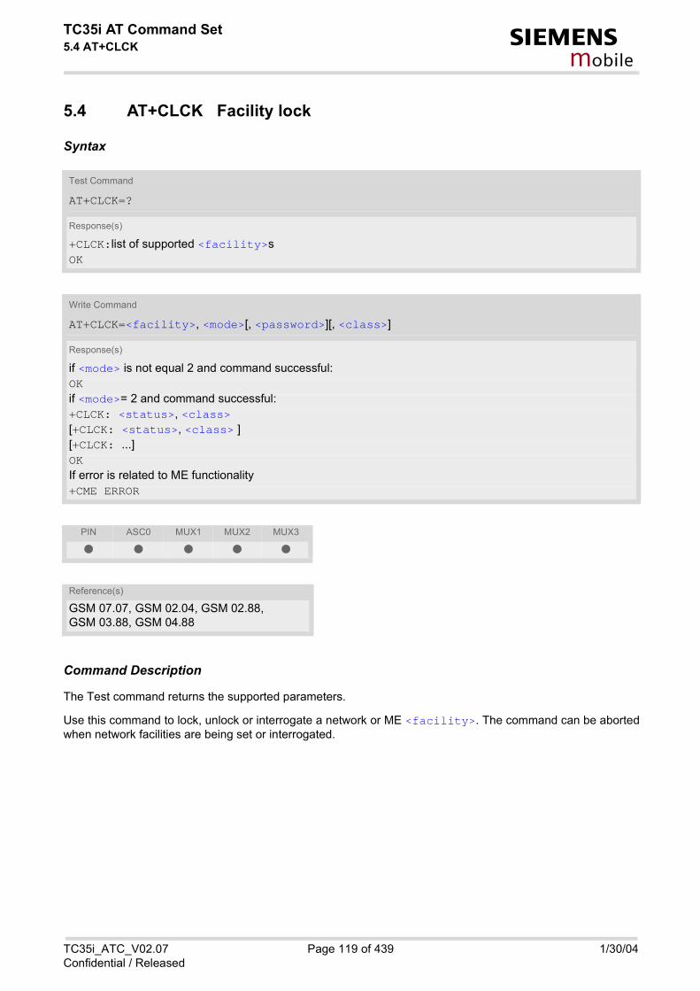
TC35i AT Command Set5.4 AT+CLCK s
mobile
5.4 AT+CLCK Facility lock
Syntax
Command Description
The Test command returns the supported parameters.
Use this command to lock, unlock or interrogate a network or ME <facility>. The command can be abortedwhen network facilities are being set or interrogated.
Test Command
AT+CLCK=?
Response(s)
+CLCK:list of supported <facility>s OK
Write Command
AT+CLCK=<facility>, <mode>[, <password>][, <class>]
Response(s)
if <mode> is not equal 2 and command successful: OKif <mode>= 2 and command successful: +CLCK: <status>, <class> [+CLCK: <status>, <class> ][+CLCK: ...]OKIf error is related to ME functionality +CME ERROR
PIN ASC0 MUX1 MUX2 MUX3
� � � � �
Reference(s)
GSM 07.07, GSM 02.04, GSM 02.88, GSM 03.88, GSM 04.88
TC35i_ATC_V02.07 Page 119 of 439 1/30/04Confidential / Released

TC35i AT Command Set5.4 AT+CLCK s
mobile
Parameter Description
Phone security locks set by client or factoryPrimarily intended for the client to take safety precautions, "SC", "PS" and "FD" can be configured individually."PS" may also be factory set. Parameter <class> is not applicable to security locks.See examples below for further details.
“SC“ SIM (lock SIM cards). SIM requests password upon ME power-up and whenthis lock command is issued.<password>: SIM PIN1.
“PS“ Phone locked to SIM card. ME requests password when other than current SIMcard is inserted."PS" lock is frequently referred to as "phone lock", or "device lock". Accord-ingly, the password may be called "phone code" or "device code". The "PS"password is not associated with the PUK of the SIM card. If incorrectly enteredthree times, the Master Phone Code is required to lift the lock. This is an 8-digitdevice code associated to the IMEI number of the mobile which can only byobtained from the manufacturer of the module. Once the Master Phone Codehas been acctepted, the mobile is operational, and the "PS" lock is no longeractive. If needed it must be set once again.<password>: User defined password. It is needed before the first use of<facility> "PS" and, therefore, must first be specified with AT+CPWD orAT^SPWD, if it has not been predefined by factory settings. If set by factory (e.g.for a prepaid mobile), the password is supplied by the provider or operator.
“FD“ SIM fixed dialling memory: If the mobile is locked to "FD", only the phone num-bers stored to the "FD" memory can be dialled. (Capacity of FD phonebookdepending on the SIM card).<password>: SIM PIN 2.If a lock on the SIM fixed dialing memory is active, the following applies: • Outgoing voice, data or fax calls can be made only to numbers stored in
''FD'' phonebook. Result code depends on the type of the call:for voice calls, indication is ''+CME Error 257: Call barred''.for data and fax calls, indication is ''NO CARRIER''.
• Access to defined Supplementary Services such as Call barring, Call wait-ing, Call forwarding, Call hold and Multiparty is possible only if the exact cor-responding public MMI *# code for the desired service is stored in the fixeddialing number phone book, and used with ATD.AT commands for supplementary service control are barred while "FD" lockis active.Indication is ''+CME Error 257: Call barred''.
• Access to Unstructured Supplementary Services (''USSD'') is possible onlyif the exact desired USSD string is stored in the fixed dialling number phonebook, and used with ATD.AT commands for USSD are barred while "FD" lock is active.Indication is ''+CME Error 257: Call barred''.
• SMS can be sent only to phone numbers which are stored in the ''fixed dial-ling numbers'' phonebook ''FD''.Indication is ''+CMS Error 302: operation not allowed''.
<facility>(str)
TC35i_ATC_V02.07 Page 120 of 439 1/30/04Confidential / Released

TC35i AT Command Set5.4 AT+CLCK s
mobile
Factory defined SIM locks:Typical examples of factory set SIM locks are prepaid phones or network locks, used to restrict the operation ofa mobile to a specific provider or operator. The client should be aware that each of these lock types can only beunlocked if the associated password is available. For example, a mobile can be locked to accept only SIM cardsfrom the respective provider, or even one single SIM card. Once a different SIM card is inserted the ME willprompt the client to enter a specific code. This is not the PUK of the SIM card, but usually an 8-digit code whichneeds to be requested from the provider.The locks can only be set by the manufacturer and need to be agreed upon between the parties concerned, e.g.provider, operator, distributor etc. on the one side and the manufacturer on the other side. For details contactyour local dealer or Siemens AG.Parameter <class> is not applicable to SIM locks.<password> and instructions for unlocking must be obtained from the network provider.
“PF“ lock Phone to the very First SIM card
“PN“ Network Personalisation
“PU“ Network subset Personalisation
“PP“ Service Provider Personalisation
“PC“ Corporate Personalisation
Supplementary Service Call Barring:Supplementary Service "Call Barring" allows to specify conditions under which calls will be disallowed by thenetwork.The availability of the Supplementary Services varies with the network. To benefit from call barring the client willneed to subscribe them, though a limited number of call barring types may be included in the basic tariff pack-age. When you attempt to set a <facility> or <class> which is not provisioned, not yet subscribed to, or not sup-ported by the module, the setting will not take effect regardless of the response returned. The responses in thesecases vary with the network (for example "OK", "+CME ERROR: Operation not allowed", "+CME ERROR: Oper-ation not supported" etc.). To make sure check the extended error response with AT+CEER and the lock statuswith <mode>=2. <password>: Network password supplied from the provider or operator. Usually there is one password whichapplies to all call barring options. For details contact your provider.
“AO“ BAOC (Bar All Outgoing Calls)
“OI“ BOIC (Bar Outgoing International Calls)
“OX“ BOIC-exHC (Bar Outgoing International Calls except to Home Country)
“AI“ BAIC (Bar All Incoming Calls)
“IR“ BIC-Roam (Bar Incoming Calls when Roaming outside the home country)
“AB“ All Barring services (applicable only for <mode>=0)
“AG“ All outGoing barring services (applicable only for <mode>=0)
“AC“ All inComing barring services (applicable only for <mode>=0)
0 unlock
1 lock
2 query status
<mode>(num)
TC35i_ATC_V02.07 Page 121 of 439 1/30/04Confidential / Released

TC35i AT Command Set5.4 AT+CLCK s
mobile
0 lock is inactive
1 lock is active
Password string used to lock and to unlock a <facility>. Length and authority for passwords depend on the<facility> in question and are therefore listed in the section on parameter <facility>. Passwords can bemodified with AT+CPWD or AT^SPWD.
Integer or sum of integers each representing a class of information, i.e. a bearer service, telecommunication ser-vice or bearer service group as defined in "GSM 02.04".
1 voice
2 class 2 ("data") comprises all those individual data classes between 16 and128, that are supported both by the network and the MS. This means, a settingmade for class 2 applies to all individual data classes (if supported). In addition,you can assign a different setting to a specific class. For example, you can acti-vate Call Forwarding for all data classes, but deactivate it for data class 64,"dedicated packet access".
4 fax
8 SMS
16 data circuit sync
32 data circuit async
64 dedicated packet access
128 dedicated PAD access
1...[7]...255 combination of some of the above classes.For example, the default setting 7 represents the sum of the integers 1, 2 and4 (voice, data and fax).The value 255 covers all classes. If parameter "class" is omitted, the default value 7 is used.
Notes
• The AT+CLCK command offers the full range of <class> parameters according to the GSM specifications.However, when you attempt to use a service option which is not provisioned or not yet subscribed to, the set-ting will not take effect regardless of the response returned.The responses in these cases vary with the network (for example "OK", "Operation not allowed", "Operationnot supported" etc.). To make sure check the extended error response with AT+CEER and the lock status with<mode>=2.
• The command has been implemented with the full set of <class> parameters according to GSM 07.07. Foractual applicability of a desired Call barring service to a specific service or service group (a specific <class>value) please consult table A.1 of GSM 02.04.
• If an outgoing Fax or Data Call is rejected due to an active ''call barring'' supplementary service, the call willbe terminated with result code NO CARRIER.Under the same conditions, an outgoing Voice call will be terminated with result code NO DIALTONE.
<status>(num)
<password>(str)
<class>(num)
TC35i_ATC_V02.07 Page 122 of 439 1/30/04Confidential / Released

TC35i AT Command Set5.4 AT+CLCK s
mobile
Examples
EXAMPLE 1
Lock SIM card (<facility>= "SC")
To query the status of the SIM card lock:
EXAMPLE 2
Phone lock (<facility>="PS")
To lock the ME to the currently insertd SIM card, first specify a password for <facility> "PS":
Optionally, if "PS" password was defined before, change existing password:
Then, activate the Phone Lock:
To operate the mobile with the SIM card for which "PS" lock was activated:
AT+CLCK="SC",1,"9999" The "SC" parameter enables or disables the SIM PIN authentication (PIN 1) when you power up the GSM engine
OK SIM card locked. As a result, SIM PIN 1 must be entered to enable ME to register to the GSM net-work.
AT+CLCK="SC",0,"9999" Unlocks SIM card. OK When powered up, ME registers to the GSM network
without requesting SIM PIN1. Note: Depending on the services offered by the pro-vider, this feature is not supported by all SIM card types. If so, the command returns ERROR when you attempt to unlock the card.
AT+CLCK="SC",2 Query the status of SIM card lock. +CLCK: 1 SIM card is locked. SIM PIN1 must be entered to
enable ME to register to the GSM network. OK
AT+CPIN? Make sure that PIN1 authentication is valid. OK
AT+CPWD="PS",,"1234" If "PS" lock has not been set before: enter new pass-word.
OK
AT+CPWD="PS","1234","3333" To replace existing "PS" password: Enter old and new password.
OK
AT+CLCK="PS",1,"3333" Locks the mobile to the current SIM card. OK
AT+CPIN?
+CPIN: SIM PIN
OK
AT+CPIN="9999"
OK No additional password is required for operation (SIM recognized by mobile).
TC35i_ATC_V02.07 Page 123 of 439 1/30/04Confidential / Released

TC35i AT Command Set5.4 AT+CLCK s
mobile
To operate the mobile with other SIM card than the one used for the "PS" lock: Enter SIM PIN of present card, followed by "PS" lock password.
To deactivate the Phone Lock:
AT+CPIN?
+CPIN: SIM PIN
OK
AT+CPIN="1111"
OK PIN authentication accepted. AT+CPIN?
+CPIN: PH-SIM PIN "PS" lock password is required. OK
AT+CPIN="3333"
OK "PS" Lock password has been accepted. ME is fully operational now.
AT+CLCK="PS",0,"3333" Phone Lock password has to be provided again. OK Now the mobile can be used with any SIM card, with-
out the need of the phone lock password.
TC35i_ATC_V02.07 Page 124 of 439 1/30/04Confidential / Released

TC35i AT Command Set5.5 AT^SLCK s
mobile
5.5 AT^SLCK Facility lock
AT command AT^SLCK provides the "Facility lock" function as described for AT command AT+CLCK defined inGSM 07.07.It is identical in every respect to AT+CLCK, except that the command syntax and response prefix is "^SLCK"instead of "+CLCK".
Syntax
Command Description
The Test command returns the supported parameters.
Use this command to lock, unlock or interrogate a network or ME <facility>. The command can be abortedwhen network facilities are being set or interrogated.
Note
• For further details please refer to AT+CLCK.
Test Command
AT^SLCK=?
Response(s)
^SLCK:list of supported <facility>s OK
Write Command
AT^SLCK=<facility>, <mode>[, <password>][, <class>]
Response(s)
if <mode> is not equal 2 and command successful: OKif <mode>= 2 and command successful: ^SLCK: <status>, <class> [^SLCK: <status>, <class> ][^SLCK: ...]OKIf error is related to ME functionality +CME ERROR
PIN ASC0 MUX1 MUX2 MUX3
� � � � �
Reference(s)
SIEMENS, GSM 07.07, GSM 02.04, GSM 02.88, GSM 03.88, GSM 04.88
TC35i_ATC_V02.07 Page 125 of 439 1/30/04Confidential / Released

TC35i AT Command Set5.6 AT+CPWD s
mobile
5.6 AT+CPWD Change Password
Use this command when you want to change the passwords defined for the "facility lock" functions available fromAT+CLCK. A password consists of a string of numeric digits with a length in the range specified by <passwordlength>. Specifically the command can be used to • change PIN1 or PIN2, • change the password supplied from your provider for the "call barring" supplementary service, • set individual phone security passwords, • enter the unblocking key (Master Phone Code) to restore a disabled "PS" password. See AT commands AT+CLCK and AT^SLCK for more information on the various lock features.
Syntax
Command Description
The test command returns a list of pairs which represent the available facilities and the maximum length of theassociated password.
The write command allows to define a new password for a password protected <facility> lock function. Eachpassword is a string of digits, the length of which varies with the associated <facility>.
Test Command
AT+CPWD=?
Response(s)
+CPWD:(list of supported (<facility>, <password length>) OK
Write Command
AT+CPWD=<facility>, <old password>[, <new password>]
Response(s)
New password has been registered for the facility lock function. OKIf parameter <old password> was not correct:+CME ERROR 16 (+CME ERROR: incorrect password)If the password for the selected <facility> has been invalidated due to too many failed attempts:+CME ERROR ...If error is related to ME functionality: +CME ERROR
PIN ASC0 MUX1 MUX2 MUX3
� � � � �
Reference(s)
GSM 07.07
TC35i_ATC_V02.07 Page 126 of 439 1/30/04Confidential / Released

TC35i AT Command Set5.6 AT+CPWD s
mobile
Parameter Description
Phone security locks set by client or factory:Primarily intended for the client to take safety precautions, passwords "SC" (SIM PIN) and "P2" (SIM PIN2) areusually predefined, but can be configured individually. The password for lock facility "PS" may also be factoryset.
“SC“ SIM PIN. SIM requests password upon ME power-up and when this lock com-mand is issued.If incorrectly entered three times, the SIM PUK is required to perform authen-tication. Input of the SIM PUK password is possible only with AT commandAT+CPIN or ATD. For further details please refer to chapter 5.1.1.<password length>: 4 to 8 digits.
“PS“ Phone locked to SIM card. ME requests password when other than current SIMcard is inserted."PS" lock is frequently referred to as "phone lock", or "device lock". Accord-ingly, the password may be called "phone code" or "device code". The "PS"password is not associated with the PUK of the SIM card. It must be definedbefore the first use of <facility> "PS" with AT+CLCK. <password length>: 4 digits. If incorrectly entered three times, the Master Phone Code is required to lift thelock. This Unblocking procedure is performed with AT+CPWD using the follow-ing parameters: <facility>="PS", <old password>= Master Phone Code(to be obtained from the module manufacturer), and <new password>= thenew phone code ("PS" password for lock facility), if desired.Mind that successful PIN authentication is a prerequisite for use of AT com-mand AT+CPWD. If Pin authentication has not been completed, input of theMaster Phone code password is possible only with AT command AT+CPIN orATD. For further detail please refer to chapter 5.1.1.Once the Master Phone Code has been acctepted, the mobile is operational,and the "PS" lock is no longer active. If needed it must be set once again withAT+CLCK.
“P2“ SIM PIN 2, e.g. required for authentication with facility lock "FD" (cf. AT+CLCK).If incorrectly entered three times, the SIM PUK 2 is required to perform authen-tication. Input of the SIM PUK 2 password is possible only with AT commandAT+CPIN2 or ATD. For further detail please refer to chapter 5.1.1.<password length>: 4 to 8 digits.
Factory defined SIM locks:Typical examples of factory set SIM locks are prepaid phones or network locks, used to restrict the operation ofa mobile to a specific provider or operator. The client should be aware that each of these lock types can only beunlocked if the associated password is available. For example, a mobile can be locked to accept only SIM cardsfrom the respective provider, or even one single SIM card. Once a different SIM card is inserted the ME willprompt the client to enter a specific code. This is not the PUK of the SIM card, but usually an 8-digit code whichneeds to be requested from the provider.The locks can only be set by the manufacturer and need to be agreed upon between the parties concerned, e.g.provider, operator, distributor etc. on the one side and the manufacturer on the other side. For details contactyour local dealer or Siemens AG.
“PF“ lock Phone to the very First SIM card
“PN“ Network Personalisation
“PU“ Network subset Personalisation
<facility>(str)
TC35i_ATC_V02.07 Page 127 of 439 1/30/04Confidential / Released

TC35i AT Command Set5.6 AT+CPWD s
mobile
“PP“ Service Provider Personalisation
“PC“ Corporate Personalisation
Supplementary Service Call Barring:Supplementary Service "Call Barring" allows to specify conditions under which calls will be disallowed by thenetwork.The availability of the Supplementary Services varies with the network. To benefit from call barring the client willneed to subscribe them, though a limited number of call barring types may be included in the basic tariff pack-age. <password length>: The Network Password needs to be supplied from the network provider or network oper-ator. Usually there is one 4 digit password which applies to all call barring options. For details contact your pro-vider.
“AO“ BAOC (Bar All Outgoing Calls)
“OI“ BOIC (Bar Outgoing International Calls)
“OX“ BOIC-exHC (Bar Outgoing International Calls except to Home Country)
“AI“ BAIC (Bar All Incoming Calls)
“IR“ BIC-Roam (Bar Incoming Calls when Roaming outside the home country)
“AB“ All Barring services
“AG“ All outGoing barring services
“AC“ All inComing barring services
4...8 length of password. The range of permitted length for a password depends onthe associated <facility>. It is available from the test command response,or in the description of parameter <facility>.
Password specified for the facility. Parameter <old password> can be ignored if no old password was allocated to the facility. Take into account that a password may have already been set by factory, or that the service is subject to a pass-word issued by the provider. See notes above or contact provider.
New password. Mandatory, if <old password> was an unblocking key (such as the Master Phone Code).
Note
• To delete a password use the following syntax: at+cpwd=<facility>,<old password>
Examples
EXAMPLE 1
To change PIN2
<password length>(num)
<old password>(str)
<new password>(str)
AT+CPWD="P2","0000","8888" (where "0000" = old PIN2 and "8888" = new PIN2) OK PIN2 Password has been changed to "8888"
TC35i_ATC_V02.07 Page 128 of 439 1/30/04Confidential / Released

TC35i AT Command Set5.6 AT+CPWD s
mobile
EXAMPLE 2
To set password used to enable or disable barring of all outgoing calls:
EXAMPLE 3
Handling of the "PS" lock password
EXAMPLE 4
To specify a new "PS" lock password, after the old password was disabled (e.g. after three failed attempts tochange the "PS" password): use the master phone code. CAUTION: THIS TEST SHOULD BE PERFORMED ONLY IF THE CORRECT MASTER PHONE CODE FORTHE INDIVIDUAL ME USED IS DEFINITELY AVAILABLE! Otherwise the module used will be rendered use-less until the correct master phone code is entered!:
Alternatively, without giving a new password:
AT+CPWD="AO","0000","3333" Requests the network to change the password for supplementary service "call barring".Ususally this request will affect all barring services, even though the request is issued for Supplementary Service BAOC ("Barring of all outgoing calls") only. Refer to the respective network provider for detail.
OK
AT+CMEE=2 Enable text output of CME Error information AT+CPWD="PS","1111","2222" (where "1111" = old password and "2222" = new
password) OK Password for facility "PS" is now "2222" AT+CPWD="PS","1111","2222" Repeat command to provoke error "incorrect pass-
word" +CME ERROR: incorrect password ("1111" is no longer the correct password)
AT+CPWD="PS","12345678","1111" where 12345678 is the Master Phone Code and 1111 is the new password. You may also use <new password> to restore the former disabled pass-word.
OK
AT+CPWD="PS","12345678" (where 12345678 is the Master Phone Code). Deac-tivates the present phone lock.
OK
TC35i_ATC_V02.07 Page 129 of 439 1/30/04Confidential / Released

TC35i AT Command Set5.7 AT^SPWD s
mobile
5.7 AT^SPWD Change Password
Use this command when you want to change the passwords defined for the "facility lock" functions available fromAT+CLCK. Specifically the command can be used to • change PIN1 or PIN2, • change the password supplied from your provider for the "call barring" supplementary service, • set individual phone security passwords, • enter the unblocking key (Master Phone Code) to restore a disabled "PS" password. See AT commands AT+CLCK and AT^SLCK for more information on the various lock features. AT command AT^SPWD is identical in every respect to AT+CPWD, except that the command syntax and responseprefix is "^SPWD" instead of "+CPWD".
Syntax
Command Description
The test command returns a list of pairs which represent the available facilities and the maximum length of theassociated password.
The write command allows to define a new password for a password protected <facility> lock function. Eachpassword is a string of digits, the length of which varies with the associated <facility>.
Note
• For further description please refer to AT+CPWD.
Test Command
AT^SPWD=?
Response(s)
^SPWD:(list of supported (<facility>, <password length>) OK
Write Command
AT^SPWD=<facility>, <old password>[, <new password>]
Response(s)
New password has been registered for the facility lock function. OKIf parameter <old password> was not correct:+CME ERROR 16 (+CME ERROR: incorrect password)If the password for the selected <facility> has been invalidated due to too many failed attempts:+CME ERROR ...If error is related to ME functionality: +CME ERROR
PIN ASC0 MUX1 MUX2 MUX3
� � � � �
TC35i_ATC_V02.07 Page 130 of 439 1/30/04Confidential / Released

TC35i AT Command Set6. Identification Commands s
mobile
6. Identification Commands
The AT Commands described in this chapter allow the external application to obtain various identification infor-mation related to the TC35i and linked entities.
6.1 ATI Display product identification information
Syntax
Command Description
ME issues product information text.Explanation of 'Revision' parameter: Version xx and variant yy of software release.
ME issues additional identification informations, after using with optional parameter.ATI9 delivers the information above. Other values are not supported and only return OK.
Parameter Description
9 SIEMENS Gipsy Soft Protocolstack V2.550
Exec Command
ATI
Response(s)
SIEMENSTC35iREVISION xx.yyOK
Exec Command
ATI[<value>]
Response(s)
[SIEMENS Gipsy Soft Protocolstack V2.550]OK
PIN ASC0 MUX1 MUX2 MUX3
� � � � �
Reference(s)
V.25ter
<value>(num)
TC35i_ATC_V02.07 Page 131 of 439 1/30/04Confidential / Released

TC35i AT Command Set6.2 AT+CGMI s
mobile
6.2 AT+CGMI Request manufacturer identification
Syntax
Command Description
TA returns manufacturer identification text.
Note
• See also: AT+GMI.
Test Command
AT+CGMI=?
Response(s)
OK
Exec Command
AT+CGMI
Response(s)
SIEMENSOK
PIN ASC0 MUX1 MUX2 MUX3
� � � � �
Reference(s)
GSM 07.07
TC35i_ATC_V02.07 Page 132 of 439 1/30/04Confidential / Released

TC35i AT Command Set6.3 AT+GMI s
mobile
6.3 AT+GMI Request manufacturer identification
Syntax
Command Description
TA reports information to identify the manufacturer.
Note
• See also: AT+CGMI
Test Command
AT+GMI=?
Response(s)
OK
Exec Command
AT+GMI
Response(s)
SIEMENSOK
PIN ASC0 MUX1 MUX2 MUX3
� � � � �
Reference(s)
V.25ter
TC35i_ATC_V02.07 Page 133 of 439 1/30/04Confidential / Released

TC35i AT Command Set6.4 AT+CGMM s
mobile
6.4 AT+CGMM Request model identification
Syntax
Command Description
TA returns product model identification text.
Note
• See also: AT+GMM.
Test Command
AT+CGMM=?
Response(s)
OK
Exec Command
AT+CGMM
Response(s)
TC35iOK
PIN ASC0 MUX1 MUX2 MUX3
� � � � �
Reference(s)
GSM 07.07
TC35i_ATC_V02.07 Page 134 of 439 1/30/04Confidential / Released

TC35i AT Command Set6.5 AT+GMM s
mobile
6.5 AT+GMM Request TA model identification
Syntax
Command Description
TA reports one or more lines of information text which permit the user to identify the specific model of device.
Note
• See also: AT+CGMM
Test Command
AT+GMM=?
Response(s)
OK
Exec Command
AT+GMM
Response(s)
TC35iOK
PIN ASC0 MUX1 MUX2 MUX3
� � � � �
Reference(s)
V.25ter
TC35i_ATC_V02.07 Page 135 of 439 1/30/04Confidential / Released

TC35i AT Command Set6.6 AT+CGMR s
mobile
6.6 AT+CGMR Request revision identification of software status
Syntax
Command Description
TA returns product firmware version identification text.
Parameter Description
Version xx and variant yy of software release.
Note
• See also: AT+GMR.
Test Command
AT+CGMR=?
Response(s)
OK
Exec Command
AT+CGMR
Response(s)
REVISION <xx.yy>OK
PIN ASC0 MUX1 MUX2 MUX3
� � � � �
Reference(s)
GSM 07.07
<xx.yy>(str)
TC35i_ATC_V02.07 Page 136 of 439 1/30/04Confidential / Released

TC35i AT Command Set6.7 AT+GMR s
mobile
6.7 AT+GMR Request TA revision identification of software status
Syntax
Command Description
TA returns product software version identification text.
Parameter Description
Version xx and variant yy of software release.
Note
• See also: AT+CGMR
Test Command
AT+GMR=?
Response(s)
OK
Exec Command
AT+GMR
Response(s)
REVISION <xx.yy>OK
PIN ASC0 MUX1 MUX2 MUX3
� � � � �
Reference(s)
V.25ter
<xx.yy>(text)
TC35i_ATC_V02.07 Page 137 of 439 1/30/04Confidential / Released

TC35i AT Command Set6.8 AT+CGSN s
mobile
6.8 AT+CGSN Request product serial number identification (IMEI) identical to GSN
Syntax
Command Description
TA returns identification text for determination of the individual ME.
Parameter Description
IMEI of the telephone (International Mobile station Equipment Identity)
Note
• See also: AT+GSN.
Test Command
AT+CGSN=?
Response(s)
OK
Exec Command
AT+CGSN
Response(s)
<sn>OK
PIN ASC0 MUX1 MUX2 MUX3
� � � � �
Reference(s)
GSM 07.07
<sn>(str)
TC35i_ATC_V02.07 Page 138 of 439 1/30/04Confidential / Released

TC35i AT Command Set6.9 AT+GSN s
mobile
6.9 AT+GSN Request TA serial number identification(IMEI)
Syntax
Command Description
TA reports one or more lines of information text which permit the user to identify the individual device.
Parameter Description
IMEI of the telephone (International Mobile station Equipment Identity)
Note
• The serial number (IMEI) varies for every individual ME device.
Test Command
AT+GSN=?
Response(s)
OK
Exec Command
AT+GSN
Response(s)
<sn>OK
PIN ASC0 MUX1 MUX2 MUX3
� � � � �
Reference(s)
V.25ter
<sn>(str)
TC35i_ATC_V02.07 Page 139 of 439 1/30/04Confidential / Released

TC35i AT Command Set6.10 AT+CIMI s
mobile
6.10 AT+CIMI Request international mobile subscriber identity
Syntax
Command Description
TA returns IMSI for identifying the individual SIM which is attached to ME.
Parameter Description
International Mobile Subscriber Identity (string without quotes).
Test Command
AT+CIMI=?
Response(s)
OK
Exec Command
AT+CIMI
Response(s)
<imsi>OKERROR+CME ERROR: <err>
PIN ASC0 MUX1 MUX2 MUX3
� � � � �
Reference(s)
GSM 07.07
<imsi>(str)
TC35i_ATC_V02.07 Page 140 of 439 1/30/04Confidential / Released

TC35i AT Command Set7. Call related Commands s
mobile
7. Call related Commands
The AT Commands described in this chapter are related to Mobile Originated (MOC, i.e. outgoing) Calls and Mobile Terminated (MTC, i.e. incoming) Calls.
7.1 ATA Answer a call
Syntax
Command Description
TA causes remote station to go off-hook (e.g. answer call).
Parameter Description
Connection status<text> output only if ATX parameter setting with value greater 0.
Notes
• Any additional commands on the same command line are ignored.
• The command may be aborted generally by receiving a character during execution. It can't be aborted insome connection setup states, such as handshaking.
• if AT+FCLASS setting is 1 or 2, all incoming calls will be answered as fax calls, if ATA is issued on multiplexerchannel 1 resp. ASC0. For calls explicitly signalled as voice or data calls, this procedure will fail with result
Exec Command
ATA
Response(s)
In case of data call, if successfully connected:CONNECT <text> TA switches to data mode.In case of voice call, if successfully connected:OKWhen TA returns to command mode after call release:OKIf no connection:NO CARRIER
PIN ASC0 MUX1 MUX2 MUX3
� � � � �
Reference(s)
V.25ter
<text>(str)
TC35i_ATC_V02.07 Page 141 of 439 1/30/04Confidential / Released

TC35i AT Command Set7.1 ATA s
mobile
code "NO CARRIER", but the call in question will continue to ring.It is possible to change the setting for AT+FCLASS to 0 while the call is ringing, and accept the call normallyafterwards with ATA.
• See also ATX for <text>.
TC35i_ATC_V02.07 Page 142 of 439 1/30/04Confidential / Released

TC35i AT Command Set7.2 ATD s
mobile
7.2 ATD Mobile originated call to dial a number
Syntax
Command Description
This command can be used to set up outgoing voice, data or fax calls. It also serves to control SupplementaryServices. The termination character ";" is mandatory to set up voice calls or to send *# codes for SupplementaryServices. It must not be used for data and fax calls.
Additional notes on the responses returned after dialing with ATD: • For voice calls, you have the choice of two different response modes that can be selected with AT^SM20:
AT^SM20=1 (factory default) causes the ME to respond once the call setup is completed either successfully("OK") or unsuccessfully ("NO CARRIER", "NO DIAL TONE", "BUSY"). AT^SM20=0 causes the ME to return "OK" immediately after dialing was completed (i.e. before call setup ter-minates successfully or unsuccessfully).
• For data connections, call setup always terminates when the call has been established (indicated by the resultcode "CONNECT <text>), or when it fails (indicated by "NO CARRIER"). The settings of AT^SM20 do notapply.
Different call release indications: • Upon termination, an outgoing fax or data call may show a different result code than a voice call would show
under identical conditions. In order to track down the actual reason for call termination, AT+CEER or ATS18should be used for all applicable connections.
Exec Command
ATD<n>[<mgsm>][;]
Response(s)
If no dialtone (parameter setting ATX2 or ATX4):NO DIALTONEIf busy (parameter setting ATX3 or ATX4):BUSYIf a connection cannot be set up:NO CARRIEROKIf successfully connected and non-voice call (TA switches to online data mode):CONNECT <text>When TA returns to command mode after call release:OKIf successfully connected and voice call:OK
PIN ASC0 MUX1 MUX2 MUX3
� � � � �
Reference(s)
V.25ter
TC35i_ATC_V02.07 Page 143 of 439 1/30/04Confidential / Released

TC35i AT Command Set7.2 ATD s
mobile
Using ATD during an active call: • When a user originates a second voice call whil there is already an active voice call, the first call will automat-
ically put on hold. The second call attempt is acknowledged with "OK" immediately after dialing with ATD hascompleted, without relation to a successful call setup. In case of failure, the additional result codes "NO CAR-RIER", "NO DIAL TONE", "NO CARRIER" will be presented afterwards (see example below).
Parameter Description
String of dialing digits and optional V.25ter modifiers: 0-9, *, #, +, A, B, CThe following V.25ter modifiers are ignored: ,(comma), T, P, !, W ,@Emergency call: <n> = 112 standardized GSM emergency number (no SIM needed).
String of GSM modifiers:I Activates CLIR (disables presentation of own phone number to called party)i Deactivates CLIR (enables presentation of own phone number to called party)G Activate Closed User Group explicit invocation for this call only.g Deactivate Closed User Group explicit invocation for this call only.
Notes
• The command may be aborted generally when receiving an ATH command during execution. It cannot beaborted in some connection setup states, such as handshaking.
• Parameter "I" and "i" only if no *#-code is within the dial string.
• <mgsm> is not supported for data calls.
• <n> is default for last number that can be dialled by ATDL.
• See also ATX for <text>.
• If ATD is used with a USSD command (e.g. ATD*100#;) an AT+CUSD=1 is executed implicitly (see AT+CUSD).
• Parameter 'G' or 'g' will be ignored if Closed User Group was already activated, respectively deactivated withAT+CCUG command before. Call by call invocation of CUG uses the settings provisioned by the provider or,if available, the settings of the parameters <index> and <info> made with AT+CCUG.
• The ME is equipped with a "Blacklist" function according to GSM02.07 Annex A:After a predefined number of failed call attempts, the dialed number is entered into a read-only phonebookcalled "blacklist" (phonebook "BL"). Call attempts to numbers contained in the blacklist will be barred by MEand not signalled to the network.An attempt to start a voice call to a barred phone number will be stopped with a CME ERROR 257 "CallBarred".An attempt to start a data or fax call to a barred phone number will be answered immediately with result code"NO CARRIER".The barred numbers are automatically removed from the blacklist according to the timing conditions specifiedin GSM02.07 Annex A.
• To start the ATD command automatically on DTR signal activation AT%D may be used.
<n>(text)
<mgsm>(str)
TC35i_ATC_V02.07 Page 144 of 439 1/30/04Confidential / Released

TC35i AT Command Set7.2 ATD s
mobile
Example
The following example shows the call setup procedure when a call is already active and a second call attemptfails because the line of the called party is busy:
atd03012345678 Dialing out the first party's number.OK The first call is established.ATD03022222222 The number of the second party is dialed.OK The response "OK" is issued immediately though no call is established
(same behavior as is you had chosen AT^SM20=0.)BUSY Line of the second called party is busy.
TC35i_ATC_V02.07 Page 145 of 439 1/30/04Confidential / Released

TC35i AT Command Set7.3 ATD><mem><n> s
mobile
7.3 ATD><mem><n> Originate call to phone number in memory
Syntax
Command Description
TA attempts to set up an outgoing call to the specified number. The termination character ";" is mandatory sincedialing from a phonebook is only supported for voice calls and for sending *# codes of Supplementary Servicesor other functions.
Parameter Description
Phonebook storage:For detailed description of storages see AT+CPBS.
“FD“ Fixed dialing phonebook
“SM“(&F) SIM phonebook
“ON“ MSISDN list
“ME“ Mobile Equipment Phonebook
“LD“ Last number dialed phonebook
“MC“ Missed (unanswered received) calls list
“RC“ Received calls list
Exec Command
ATD><mem><n>[<mgsm>];
Response(s)
ERROR+CME ERROR: <err>If no dialtone (parameter ATX2 or ATX4):NO DIALTONEIf busy (parameter setting ATX3 or ATX4):BUSYIf connection cannot be set up:NO CARRIERWhen TA returns to command mode after call release:OKIf successfully connected:OK
PIN ASC0 MUX1 MUX2 MUX3
� � � � �
Reference(s)
V.25ter
<mem>(str)
TC35i_ATC_V02.07 Page 146 of 439 1/30/04Confidential / Released
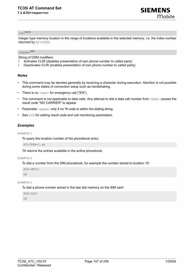
TC35i AT Command Set7.3 ATD><mem><n> s
mobile
Integer type memory location in the range of locations available in the selected memory, i.e. the index numberreturned by AT+CPBR.
String of GSM modifiers:I Activates CLIR (disables presentation of own phone number to called party)i Deactivates CLIR (enables presentation of own phone number to called party)
Notes
• This command may be aborted generally by receiving a character during execution. Abortion is not possibleduring some states of connection setup such as handshaking.
• There is no <mem> for emergency call ("EN").
• The command is not applicable to data calls. Any attempt to dial a data call number from <mem> causes theresult code "NO CARRIER" to appear.
• Parameter <mgsm> only if no *# code is within the dialing string.
• See ATX for setting result code and call monitoring parameters.
Examples
EXAMPLE 1
To query the location number of the phonebook entry:
TA returns the entries available in the active phonebook.
EXAMPLE 2
To dial a number from the SIM phonebook, for example the number stored to location 15:
EXAMPLE 3
To dial a phone number stored in the last dial memory on the SIM card:
<n>(num)
<mgsm>(str)
AT+CPBR=1,xx
ATD>SM15;
OK
ATD>LD9;
OK
TC35i_ATC_V02.07 Page 147 of 439 1/30/04Confidential / Released

TC35i AT Command Set7.4 ATD><n> s
mobile
7.4 ATD><n> Originate call to phone number selected from active memory
Syntax
Command Description
TA attempts to set up an outgoing call to the stored number. The termination character ";" is mandatory sincedialing from a phonebook is only supported for voice calls and for sending *# codes of Supplementary Servicesor other functions.
Parameter Description
Integer type memory location in the range of locations available in the selected memory, i.e. the index numberreturned by AT+CPBR.
String of GSM modifiers:I Activates CLIR (disables presentation of own phone number to called party)i Deactivates CLIR (enables presentation of own phone number to called party)
Notes
• This command may be aborted generally by receiving a character during execution. Abortion is not possible
Exec Command
ATD><n>[<mgsm>];
Response(s)
ERROR+CME ERROR: <err>If no dialtone (parameter ATX2 or ATX4):NO DIALTONEIf busy (parameter setting ATX3 or ATX4):BUSYIf connection cannot be set up:NO CARRIERWhen TA returns to command mode after call release:OKIf successfully connected:OK
PIN ASC0 MUX1 MUX2 MUX3
� � � � �
Reference(s)
V.25ter
<n>(num)
<mgsm>(str)
TC35i_ATC_V02.07 Page 148 of 439 1/30/04Confidential / Released

TC35i AT Command Set7.4 ATD><n> s
mobile
during some states of connection setup such as handshaking.
• The command is not applicable to data calls. Any attempt to dial a data call number from <n> causes theresult code "NO CARRIER" to appear.
• Parameter <mgsm> only if no *# code is within the dialing string.
TC35i_ATC_V02.07 Page 149 of 439 1/30/04Confidential / Released

TC35i AT Command Set7.5 ATD><str> s
mobile
7.5 ATD><str> Originate call to phone number in memory with corre-sponding field
Syntax
Command Description
This command searches the active phonebook for a given string <str> and dials the assigned phone number.The termination character ";" is mandatory since dialing from a phonebook is only supported for voice calls andfor sending *# codes of Supplementary Services or other functions.
Parameter Description
String type value ("x"), which should equal an alphanumeric field in at least one phonebook entry in the searchedmemories; used character set should be the one selected with AT+CSCS. <str> can contain escape sequencesas described in chapter "Supported character sets". <str> must be wrapped in quotation marks (""), if escape sequences or parameter <mgsm> are used or if thealphanumeric strings contains a blank. If not, quotation marks are optional.
String of GSM modifiers:I Activates CLIR (disables presentation of own phone number to called party)i Deactivates CLIR (enables presentation of own phone number to called party)
Exec Command
ATD><str>[<mgsm>];
Response(s)
ERROR+CME ERROR: <err>If no dialtone (parameter ATX2 or ATX4):NO DIALTONEIf busy (parameter setting ATX3 or ATX4):BUSYIf connection cannot be set up:NO CARRIERWhen TA returns to command mode after call release:OKIf successfully connected:OK
PIN ASC0 MUX1 MUX2 MUX3
� � � � �
Reference(s)
V.25ter
<str>(str)(+CSCS)
<mgsm>(str)
TC35i_ATC_V02.07 Page 150 of 439 1/30/04Confidential / Released

TC35i AT Command Set7.5 ATD><str> s
mobile
Notes
• This command may be aborted generally by receiving a character during execution. Abortion is not possibleduring some states of connection setup such as handshaking.
• The command is not applicable to data calls. Any attempt to dial <str> without semicolon ";" causes theresult code "NO CARRIER" to appear.
• Parameter <mgsm> only if no *# code is within the dialing string.
TC35i_ATC_V02.07 Page 151 of 439 1/30/04Confidential / Released

TC35i AT Command Set7.6 ATDI s
mobile
7.6 ATDI Mobile originated call to dialable ISDN number <n>
Syntax
Command Description
TA attempts to set up an outgoing call to ISDN number.
Parameter Description
ISDN number [+]<d>String with maximum length of 20 characters. Allowed characters:+: international dialing format<d>: 0-9, A, B, C
voice call.
Note
• This command may be aborted generally by receiving a character during execution. Abortion is not possibleduring some states of connection setup such as handshaking.
Exec Command
ATDI<n>[<;>]
Response(s)
If no dialtone (parameter ATX2 or ATX4):NO DIALTONEIf busy (parameter setting ATX3 or ATX4):BUSYIf connection cannot be set up:NO CARRIERIf successfully connected and non-voice call (TA switches to data state):CONNECT <text>When TA returns to command mode after call release:OKIf successfully connected and voice call:OK
PIN ASC0 MUX1 MUX2 MUX3
� � � � �
Reference(s)
V.25ter
<n>(str)
<;>(str)
TC35i_ATC_V02.07 Page 152 of 439 1/30/04Confidential / Released

TC35i AT Command Set7.7 ATDL s
mobile
7.7 ATDL Redial last telephone number used
Syntax
Command Description
This command redials the last voice and data call number used in the ATD command. If terminated with semi-colon ";" ATDL dials the last voice call number stored in the "LD" phonebook. Otherwise, the last dialed data orfax number will be used (not contained in the "LD" phonebook).
Note
• This command may be aborted generally by receiving a character during execution. Abortion is not possibleduring some states of connection setup such as handshaking.
Exec Command
ATDL[;]
Response(s)
If there is no last number or number is not valid:+CME ERRORIf no dialtone (parameter ATX2 or ATX4):NO DIALTONEIf busy (parameter setting ATX3 or ATX4):BUSYIf connection cannot be set up:NO CARRIERIf successfully connected and non-voice call (TA switches to online data mode):CONNECT <text>When TA returns to command mode after call release:OKIf successfully connected and voice call:OK
PIN ASC0 MUX1 MUX2 MUX3
� � � � �
Reference(s)
V.25ter
TC35i_ATC_V02.07 Page 153 of 439 1/30/04Confidential / Released

TC35i AT Command Set7.8 ATH s
mobile
7.8 ATH Disconnect existing connection
Syntax
Command Description
Disconnect existing call from command line by local TE and terminate call.
Parameter Description
[0] disconnect from line and terminate call
Notes
• OK is issued after circuit 109 (DCD) is turned off, if it was previously on.
• ATH terminates every circuit switched call (voice, data or fax), even if it is issued via another interface. Thisbehavior is in accordance with ITU-T V.25 ter; (07/97, "Hook control": "ATH is terminating any call inprogress.").
Exec Command
ATH[<n>]
Response(s)
OK
PIN ASC0 MUX1 MUX2 MUX3
� � � � �
Reference(s)
V.25ter
<n>(num)
TC35i_ATC_V02.07 Page 154 of 439 1/30/04Confidential / Released

TC35i AT Command Set7.9 AT+CHUP s
mobile
7.9 AT+CHUP Hang up call
Syntax
Command Description
Cancels all active and held calls.
Note
• AT+CHUP implements the same behaviour as ATH.
Test Command
AT+CHUP=?
Response(s)
OK
Exec Command
AT+CHUP
Response(s)
ERROROK
PIN ASC0 MUX1 MUX2 MUX3
� � � � �
Reference(s)
GSM 07.07
TC35i_ATC_V02.07 Page 155 of 439 1/30/04Confidential / Released

TC35i AT Command Set7.10 AT^SHUP s
mobile
7.10 AT^SHUP Hang up call(s) indicating a specific GSM04.08 release cause
Syntax
Command Description
The write command serves to end one specific call or all calls known to the ME, indicating a specific GSM04.08release cause specified by the user. The command can be used for voice, fax and data calls in any call status(i.e. any calls listed by AT+CLCC).
Parameter Description
release causeRelease cause from GSM04.08 to be indicated to the network. The TC35i will release the selected connection(s) with release cause indication "cause" and location "user" (0)in the "disconnect" protocol message to the GSM Network. It depends on the network whether or not the releasecause will be forwarded to the remote party.
1 send GSM04.08 release cause "unassigned (unallocated) number"
16 send GSM04.08 release cause "Normal call clearing "
17 send GSM04.08 release cause "User busy "
18 send GSM04.08 release cause "No user responding "
27 send GSM04.08 release cause "Destination out of order "
31 send GSM04.08 release cause "Normal, unspecified"
Test Command
AT^SHUP=?
Response(s)
OK
Write Command
AT^SHUP=<cause>[, <cn>]
Response(s)
ERROROK
PIN ASC0 MUX1 MUX2 MUX3
� � � � �
Reference(s)
Siemens
<cause>(num)
TC35i_ATC_V02.07 Page 156 of 439 1/30/04Confidential / Released

TC35i AT Command Set7.10 AT^SHUP s
mobile
call numberThe "call number" is an optional index into the list of current calls available via AT+CLCC. AT command AT^SHUPwill terminate the call identified by the specified call number. The default call number "0" is not assigned to anycall, but signifies "all calls". As "0" is the default value, it may be omitted. With AT^SHUP, Calls will be terminated regardless of their current call status, which may be any of the statesallowed by AT+CLCC.
[0] terminate all known calls
1...7 terminate the specific call number <cn>
Notes
• it depends on the network whether or not a delivered release cause will be forwarded to the remote party.
• With AT^SHUP, Calls will be terminated regardless of their current call status, which may be any of the statesallowed by AT+CLCC.
<cn>(num)
TC35i_ATC_V02.07 Page 157 of 439 1/30/04Confidential / Released

TC35i AT Command Set7.11 ATS0 s
mobile
7.11 ATS0 Set number of rings before automatically answering the call
Syntax
Command Description
This parameter setting determines the number of rings before automatic answering.
Parameter Description
000(&F) automatic answering is disabled
001-255 enable automatic answering on the specified ring number
Notes
• This command works for MT data, fax and voice calls.
• Autoanswering of CSD data and fax calls is supported on ASC0/Mux1 only.
• If <n> is set to higher values, the calling party may terminate the call establishment before the call can beautomatically answered.
• The correlation between ATS7 and ATS0 is important.Example: ATS7=30 and ATS0=20 may not allow call establishment.
• Setting is local to the interface. It is allowed to have different settings on different interfaces. In such casesthe interface 'wins', which is idle and uses the smallest <n> value.
Read Command
ATS0?
Response(s)
<n>OK
Write Command
ATS0=<n>
Response(s)
OK
PIN ASC0 MUX1 MUX2 MUX3
� � � � �
Reference(s)
V.25ter
<n>(num)(&W)(&V)
TC35i_ATC_V02.07 Page 158 of 439 1/30/04Confidential / Released

TC35i AT Command Set7.12 ATS6 s
mobile
7.12 ATS6 Set pause before blind dialing
Syntax
Command Description
No effect for GSM.
Parameter Description
000(&F)...255
Read Command
ATS6?
Response(s)
<n>OK
Write Command
ATS6=<n>
Response(s)
OK
PIN ASC0 MUX1 MUX2 MUX3
� � � � �
Reference(s)
V.25ter
<n>(num)(&W)(&V)
TC35i_ATC_V02.07 Page 159 of 439 1/30/04Confidential / Released

TC35i AT Command Set7.13 ATS7 s
mobile
7.13 ATS7 Set number of seconds to wait for connection completion
Syntax
Command Description
This parameter setting determines the amount of time to wait for the connection completion when answering ororiginating a call.
Parameter Description
no. of seconds to wait for connection completion
000...060(&F)
Notes
• Values bigger than 60 cause no error, but <n> will be set down to maximum value of 60.
• In <n> of ATS0 of the called party is set to higher values the call establishment may not be successful.
• The correlation between ATS7 and ATS0 is important.Example: ATS7=30 and ATS0=20 may not allow call establishment.
Read Command
ATS7?
Response(s)
<n>OK
Write Command
ATS7=<n>
Response(s)
OK
PIN ASC0 MUX1 MUX2 MUX3
� � � � �
Reference(s)
V.25ter
<n>(num)(&W)(&V)
TC35i_ATC_V02.07 Page 160 of 439 1/30/04Confidential / Released

TC35i AT Command Set7.14 ATS8 s
mobile
7.14 ATS8 Set number of seconds to wait for comma dialing modifier
Syntax
Command Description
No effect for GSM.
Parameter Description
Read Command
ATS8?
Response(s)
<n>OK
Write Command
ATS8=<n>
Response(s)
OK
PIN ASC0 MUX1 MUX2 MUX3
� � � � �
Reference(s)
V.25ter
<n>(num)(&W)(&V)
TC35i_ATC_V02.07 Page 161 of 439 1/30/04Confidential / Released
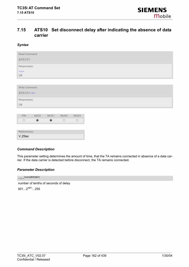
TC35i AT Command Set7.15 ATS10 s
mobile
7.15 ATS10 Set disconnect delay after indicating the absence of data carrier
Syntax
Command Description
This parameter setting determines the amount of time, that the TA remains connected in absence of a data car-rier. If the data carrier is detected before disconnect, the TA remains connected.
Parameter Description
number of tenths of seconds of delay
001...2(&F)...255
Read Command
ATS10?
Response(s)
<n>OK
Write Command
ATS10=<n>
Response(s)
OK
PIN ASC0 MUX1 MUX2 MUX3
� � � � �
Reference(s)
V.25ter
<n>(num)(&W)(&V)
TC35i_ATC_V02.07 Page 162 of 439 1/30/04Confidential / Released
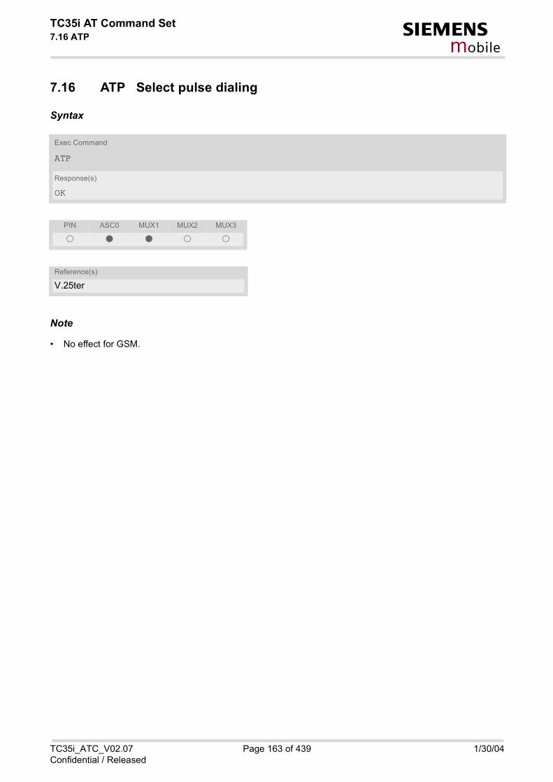
TC35i AT Command Set7.16 ATP s
mobile
7.16 ATP Select pulse dialing
Syntax
Note
• No effect for GSM.
Exec Command
ATP
Response(s)
OK
PIN ASC0 MUX1 MUX2 MUX3
� � � � �
Reference(s)
V.25ter
TC35i_ATC_V02.07 Page 163 of 439 1/30/04Confidential / Released
TC35i AT Command Set7.17 ATO s
mobile
7.17 ATO Switch from command mode to data mode
Syntax
Command Description
ATO is the corresponding command to the +++ escape sequence: When you have established a CSD call andTA is in command mode, ATO causes the TA to resume the data connection and takes you back to data modemode.
Parameter Description
[0] Switch from command mode to data mode
Exec Command
ATO[<n>]
Response(s)
If connection is not successfully resumed:NO CARRIERorTA returns to data mode from command modeCONNECT <text>Note: <text> output only if ATX parameter setting with value > 0.
PIN ASC0 MUX1 MUX2 MUX3
� � � � �
Reference(s)
V.25ter
<n>(num)
TC35i_ATC_V02.07 Page 164 of 439 1/30/04Confidential / Released

TC35i AT Command Set7.18 +++ s
mobile
7.18 +++ Switch from data mode to command mode
Syntax
Command Description
This command is only available during a data call. The +++ character sequence causes the TA to cancel the dataflow over the AT interface and switch to command mode. This allows you to enter AT commands while maintain-ing the data connection to the remote device. To prevent the +++ escape sequence from being misinterpreted as data, it must be preceded and followed by apause of at least 1000 ms. The +++ characters must be entered in quick succession, all within 1000 ms.
Note
• To return from command mode to data mode: Enter ATO.
Exec Command
+++
Response(s)
OK
PIN ASC0 MUX1 MUX2 MUX3
� � � � �
Reference(s)
V.25ter
TC35i_ATC_V02.07 Page 165 of 439 1/30/04Confidential / Released

TC35i AT Command Set7.19 ATT s
mobile
7.19 ATT Select tone dialing
Syntax
Note
• No effect for GSM.
Exec Command
ATT
Response(s)
OK
PIN ASC0 MUX1 MUX2 MUX3
� � � � �
Reference(s)
V.25ter
TC35i_ATC_V02.07 Page 166 of 439 1/30/04Confidential / Released

TC35i AT Command Set7.20 AT+CBST s
mobile
7.20 AT+CBST Select bearer service type
Syntax
Command Description
The write command selects the bearer service <name>, the data rate <speed> and the connection element<ce> to be used when data calls are originated. The settings also apply to mobile terminated data calls, espe-cially when single numbering scheme calls or calls from analog devices are received (see also: AT+CSNS).
Parameter Description
0 auto bauding
4 2400 bps (V.22bis)
6 4800 bps (V.32)
[7](&F) 9600 bps (V.32)
Test Command
AT+CBST=?
Response(s)
+CBST: (list of supported<speed>s), (list of supported<name>s), (list of supported<ce>s) OK
Read Command
AT+CBST?
Response(s)
+CBST: <speed>, <name>, <ce> OK
Write Command
AT+CBST=<speed>[, <name>[, <ce>]]
Response(s)
OKERROR+CME ERROR: <err>
PIN ASC0 MUX1 MUX2 MUX3
� � � � �
Reference(s)
GSM 07.07
<speed>(num)(&W)(&V)
TC35i_ATC_V02.07 Page 167 of 439 1/30/04Confidential / Released

TC35i AT Command Set7.20 AT+CBST s
mobile
14 14400 bps (V.34)
68 2400 bps (V.110)
70 4800 bps (V.110)
71 9600 bps (V.110)
75 14400 bps (V.110)
0(&F) asynchronous modem
Transparent mode is not supported.
1(&F) non-transparent
Note
• GSM 02.02[1]: List of allowed combinations of subparameters.
<name>(num)(&W)
<ce>(num)(&W)
TC35i_ATC_V02.07 Page 168 of 439 1/30/04Confidential / Released
TC35i AT Command Set7.21 AT+CRLP s
mobile
7.21 AT+CRLP Select radio link protocol param. for orig. non-trans-parent data call
Syntax
Command Description
Read command returns current settings for the supported RLP version 0.
The Write command sets radio link protocol (RLP) parameters used when non-transparent data calls are origi-nated.
Parameter Description
Interworking window size (IWF to MS)
0...[10]...61(&F)
Test Command
AT+CRLP=?
Response(s)
+CRLP: (list of supported<iws>s), (list of supported<mws>s), (list of supported<T1>s), (list of supported<N2>s) OK
Read Command
AT+CRLP?
Response(s)
+CRLP: <iws>, <mws>, <T1>, <N2>[, <verx>] OK
Write Command
AT+CRLP=[<iws>[, <mws>[, <T1>[, <N2>]]]]
Response(s)
OKERROR+CME ERROR: <err>
PIN ASC0 MUX1 MUX2 MUX3
� � � � �
Reference(s)
GSM 07.07
<iws>(num)(&W)(&V)
TC35i_ATC_V02.07 Page 169 of 439 1/30/04Confidential / Released

TC35i AT Command Set7.21 AT+CRLP s
mobile
Mobile window size (MS to IWF)
0...[10]...61(&F)
Acknowledgement timer (T1 in 10 ms units)
48...[78](&F)...255
Re-transmission attempts N2
1...[6](&F)...255
0 RLP version number in integer format; when version indication is not present itshall equal 0.
Notes
• RLP version 0: single-link basic version;
• RLP version 1: single-link extended version (e.g. extended by data compression);
• RLP version 2: multi-link version.
• Compression and multi-link are not supported.
<mws>(num)(&W)(&V)
<T1>(num)(&W)(&V)
<N2>(num)(&W)(&V)
<verx>(num)
TC35i_ATC_V02.07 Page 170 of 439 1/30/04Confidential / Released

TC35i AT Command Set7.22 AT+CLCC s
mobile
7.22 AT+CLCC List current calls of ME
Syntax
Command Description
The exec command returns a list of current calls of ME. If command is successful, but no calls are available, noinformation response is sent to TE.
Parameter Description
call identification number as described in GSM02.30 subclause 4.5.5.1; this number can be used in AT+CHLDcommand operations
0 mobile originated call (MOC)
1 mobile terminated call (MTC)
state of the call
0 active
Test Command
AT+CLCC=?
Response(s)
OK
Exec Command
AT+CLCC
Response(s)
[+CLCC: <idx>, <dir>, <stat>, <mode>, <mpty>[, <number>, <type>[, <alpha>]] ][+CLCC: <idx>, <dir>, <stat>, <mode>, <mpty>[, <number>, <type>[, <alpha>]] ][+CLCC: ...]OKERROR+CME ERROR
PIN ASC0 MUX1 MUX2 MUX3
� � � � �
Reference(s)
GSM 07.07
<idx>(num)
<dir>(num)
<stat>(num)
TC35i_ATC_V02.07 Page 171 of 439 1/30/04Confidential / Released

TC35i AT Command Set7.22 AT+CLCC s
mobile
1 held
2 dialing (MOC)
3 alerting (MOC)
4 incoming (MTC)
5 waiting (MTC)
bearer/teleservice
0 voice
1 data
2 fax
3 voice followed by data, voice mode (only in connection with single numberingscheme AT+CSNS)
4 alternating voice/data, voice mode (only in connection with single numberingscheme AT+CSNS)
5 alternating voice/fax, voice mode (only in connection with single numberingscheme AT+CSNS)
6 voice followed by data, data mode (only in connection with single numberingscheme AT+CSNS)
7 alternating voice/data, data mode (only in connection with single numberingscheme AT+CSNS)
8 alternating voice/fax, fax mode (only in connection with single numberingscheme AT+CSNS)
9 unknown
0 call is not one of multiparty (conference) call parties
1 call is one of multiparty (conference) call parties
phone number in format specified by <type>
type of address octect
145 dialling string <number> includes international access code character '+'
129 otherwise
Alphanumeric representation of <number> corresponding to the entry found in phonebook; used character setshould be the one selected with command AT+CSCS (Select TE Character Set). The maximum displayed length of <alpha> is 16 characters. If the <alpha> has more than 16 characters, onlythe first 15 characters will be displayed. To indicated an overflow, a special character will be used as the 16thcharacter. This will be a space if the character set selected with AT+CSCS is 'GSM', or 'E400' if the character set
<mode>(num)
<mpty>(num)
<number>(str)
<type>(num)
<alpha>(str)(+CSCS)
TC35i_ATC_V02.07 Page 172 of 439 1/30/04Confidential / Released

TC35i AT Command Set7.22 AT+CLCC s
mobile
is 'UCS2'.Due to time constraints on the necessary evaluation of the phonebook, this parameter may show a default valueduring early call phases (e.g. for <stat>= ''dialling'', ''incoming'' or ''alerting''), even if a phonebook entry ispresent for the number concerned.
Note
• teleservices other than voice, data, fax are not fully supported by ME. They are used only in connection withthe handling for AT+CSNS, and may therefore occur in parameter <mode> for mobile terminated calls.
TC35i_ATC_V02.07 Page 173 of 439 1/30/04Confidential / Released

TC35i AT Command Set7.23 AT+CR s
mobile
7.23 AT+CR Service reporting control
Syntax
Intermediate Result Code
If enabled, an intermediate result code is transmitted at the point during connect negotiation when the TA hasdetermined the speed and quality of service to be used, before any error control or data compression reports aretransmitted, and before any final result code (e.g. CONNECT) appears. +CR: <serv>
Command Description
Configures the TA whether or not to transmit an intermediate result code +CR: <serv> to TE when a call is beingset up.
Test Command
AT+CR=?
Response(s)
+CR: (list of supported<mode>s) OK
Read Command
AT+CR?
Response(s)
+CR: <mode> OK
Write Command
AT+CR=<mode>
Response(s)
OK
PIN ASC0 MUX1 MUX2 MUX3
� � � � �
Reference(s)
GSM 07.07
TC35i_ATC_V02.07 Page 174 of 439 1/30/04Confidential / Released

TC35i AT Command Set7.23 AT+CR s
mobile
Parameter Description
0(&F) disable
1 enable
“REL ASYNC“ asynchronous non-transparent
Notes
• The PLMN influences the second air interface (to the terminator), therefore another mode may be establishedfrom the network.
• Setting the value of <mode> to 1 may lead to connection failure, if the application (e.g. WinFax) waits fordefault result code/URC.
• The PIN is required for the write command only.
<mode>(num)(&W)(&V)
<serv>(str)
TC35i_ATC_V02.07 Page 175 of 439 1/30/04Confidential / Released
TC35i AT Command Set7.24 AT+CRC s
mobile
7.24 AT+CRC Set Cellular Result Codes for incoming call indication
Syntax
Unsolicited Result Code
When enabled, an incoming call is indicated to the TE with unsolicited result code +CRING: <type> instead ofthe normal RING. +CRING: <type>
Command Description
The command controls whether or not the extended format of incoming call indication is used.
Parameter Description
[0](&F) disable extended format
1 enable extended format
Test Command
AT+CRC=?
Response(s)
+CRC: (list of supported<mode>s) OK
Read Command
AT+CRC?
Response(s)
+CRC: <mode> OK
Write Command
AT+CRC=[<mode>]
Response(s)
OK
PIN ASC0 MUX1 MUX2 MUX3
� � � � �
Reference(s)
GSM 07.07
<mode>(num)(&W)(&V)
TC35i_ATC_V02.07 Page 176 of 439 1/30/04Confidential / Released

TC35i AT Command Set7.24 AT+CRC s
mobile
“REL ASYNC“ asynchronous non-transparent
“FAX“ facsimile
“VOICE“ voice
Note
• Setting the value of <mode> to 1 may lead to connection failure, if the application (e.g. WinFax) waits fordefault result code/URC.
<type>(str)
TC35i_ATC_V02.07 Page 177 of 439 1/30/04Confidential / Released

TC35i AT Command Set7.25 AT+CSNS s
mobile
7.25 AT+CSNS Single Numbering Scheme
Syntax
Command Description
The AT+CSNS command enables the ME to accept incoming calls when no bearer capability information is pro-vided with the call, e.g. single numbering scheme calls or calls originitating from analog devices.
Parameter Description
[0](D) Voice: Each call received without bearer element is assumed to be speech
2 Fax: Each call received without bearer element is assumed to be an incomingfax.
4 Data: Each call received without bearer element is assumed to be a data call.Please take into account that the bearer service parameters set with AT+CBSTapply to all data calls including those received without bearer capability.
Test Command
AT+CSNS=?
Response(s)
+CSNS: (list of supported<mode>s) OK
Read Command
AT+CSNS?
Response(s)
+CSNS: <mode> OK
Write Command
AT+CSNS=[<mode>]
Response(s)
OK
PIN ASC0 MUX1 MUX2 MUX3
� � � � �
Reference(s)
GSM 07.07
<mode>(num)
TC35i_ATC_V02.07 Page 178 of 439 1/30/04Confidential / Released
TC35i AT Command Set7.25 AT+CSNS s
mobile
Notes
• The command must be set before the call comes. By default, when you do not modify the settings, all callsreceived without bearer element are assumed to be voice.
• The setting will be automatically saved when you power down the GSM engine with AT^SMSO, provided thatPIN authentication has been done. This value will be restored when PIN authentication is done again.
TC35i_ATC_V02.07 Page 179 of 439 1/30/04Confidential / Released

TC35i AT Command Set7.26 AT^SCNI s
mobile
7.26 AT^SCNI List Call Number Information
Syntax
Command Description
TA returns a list of current calls of ME.
Parameter Description
call identification number as described in GSM 02.30[19] subclause 4.5.5.1; this number can be used inAT+CHLD command operations
1...7
Call status of respective call number (first parameter)
0 call hold
1 call in progress
2 waiting call
Test Command
AT^SCNI=?
Response(s)
OK
Exec Command
AT^SCNI
Response(s)
^SCNI: <id>1[,<cs>[,<number>,<type>]]^SCNI: <id>2[,<cs>[,<number>,<type>]][...]OKERROR+CME ERROR: <err>
PIN ASC0 MUX1 MUX2 MUX3
� � � � �
Reference(s)
SIEMENS
<id>(num)
<cs>(num)
TC35i_ATC_V02.07 Page 180 of 439 1/30/04Confidential / Released

TC35i AT Command Set7.26 AT^SCNI s
mobile
string type phone number in format specified by <type>
type of address octet in integer format; 145 when dialling string includes international access code character "+",otherwise 129
Note
• See also GSM 07.07: AT+CLCC
<number>(str)
<type>(num)
TC35i_ATC_V02.07 Page 181 of 439 1/30/04Confidential / Released

TC35i AT Command Set7.27 AT^SLCD s
mobile
7.27 AT^SLCD Display Last Call Duration
Syntax
Command Description
TA returns last call duration or current call duration.
Parameter Description
Format is "hh:mm:ss", where characters indicate hours, minutes, seconds; E.g. 22:10:00 "22:10:00"Max value is 9999:59:59
Test Command
AT^SLCD=?
Response(s)
OK
Exec Command
AT^SLCD
Response(s)
^SLCD: <time>OK
PIN ASC0 MUX1 MUX2 MUX3
� � � � �
Reference(s)
SIEMENS
<time>(str)
TC35i_ATC_V02.07 Page 182 of 439 1/30/04Confidential / Released

TC35i AT Command Set7.28 AT^STCD s
mobile
7.28 AT^STCD Display Total Call Duration
Syntax
Command Description
TA returns total call duration (accumulated duration of all calls).
Parameter Description
Format is "hh:mm:ss", where characters indicate hours, minutes, seconds; E.g. 22:10:00 "22:10:00"Max value is 9999:59:59
Note
• The Total Call Duration will not be reset by power off or other means.
Test Command
AT^STCD=?
Response(s)
OK
Exec Command
AT^STCD
Response(s)
^STCD: <time>OK
PIN ASC0 MUX1 MUX2 MUX3
� � � � �
Reference(s)
SIEMENS
<time>(str)
TC35i_ATC_V02.07 Page 183 of 439 1/30/04Confidential / Released

TC35i AT Command Set8. Network Service Commands s
mobile
8. Network Service Commands
The AT Commands described in this chapter are related to various network services. More Commands related to this area can be found at the chapter "Supplementary Service Commands".
8.1 AT+COPN Read operator names
Syntax
Command Description
TA returns the list of operator names from the ME. Each operator code <numericn> that has an alphanumericequivalent <alphan> in the ME memory is returned. See also: AT^SPLM.
Parameter Description
Operator in numeric form; GSM location area identification number.
Operator in long alphanumeric format; can contain up to 16 characters.
Test Command
AT+COPN=?
Response(s)
OK
Exec Command
AT+COPN
Response(s)
+COPN: <numericn>, <alphan>+COPN: ...OK
PIN ASC0 MUX1 MUX2 MUX3
� � � � �
Reference(s)
GSM 07.07
<numericn>(str)
<alphan>(str)
TC35i_ATC_V02.07 Page 184 of 439 1/30/04Confidential / Released

TC35i AT Command Set8.2 AT+COPS s
mobile
8.2 AT+COPS Operator selection
This command can be used to query the present status of the ME's network registration and to determinewhether automatic or manual network selection shall be used. Automatic mode: Lets the ME automatically search for the home operator. If successful the ME registers to thehome network and enters the IDLE mode. If the home network is not found, ME goes on searching. If then apermitted operator is found, ME registers to this operator. If no operator is found the ME remains unregistered. Manual mode: Desired operator can be manually entered, using the AT+COPS write command syntax. If oper-ator is found, ME registers to this operator immediately. If the selected operator is forbidden, the ME remainsunregistered. Manual/automatic: In this mode, the ME first tries to find the operator that was manually entered. If the ME failsto register to this operator, then it starts to select automatically another network.
Syntax
Test Command
AT+COPS=?
Response(s)
+COPS:[list of supported:( <stat>, long alphanumeric <oper>, , numeric <oper>)][, , list of supported <mode>s, list of supported <format>s] OKERROR+CME ERROR
Read Command
AT+COPS?
Response(s)
+COPS:<mode>[, <format>[, <oper>]] OKERROR+CME ERROR
Write Command
AT+COPS=<mode>[, <format>[, <oper>]]
Response(s)
OKERROR+CME ERROR
PIN ASC0 MUX1 MUX2 MUX3
� � � � �
Reference(s)
GSM 07.07
TC35i_ATC_V02.07 Page 185 of 439 1/30/04Confidential / Released

TC35i AT Command Set8.2 AT+COPS s
mobile
Command Description
The test command returns a list of quadruplets, each representing an operator present in the network. Any of theformats may be unavailable and will then be an empty field (,,). The list of operators comes in the following order:Home network, networks referenced in SIM, and other networks.
The read command returns the current <mode> and the currently selected operator. If no operator is selected,<format> and <oper> are omitted.
The write command forces an attempt to select and register the GSM network operator. If the selected operatoris not available, no other operator will be selected (except <mode>=4). The selected operator name format willapply to further read commands (+COPS?), too.
Parameter Description
Status
0 unknown
1 operator available
2 operator current
3 operator forbidden
OperatorParameter is stored non-volatile to the SIM. Operator as per <format>. The numeric format is the GSM Loca-tion Area Identification number which consists of a 3-digit country code plus a 2- or 3-digit network code.
parameter values 0 and 1 are stored non-volatile in the ME
0(D) automatic mode; <oper> field is ignored
1 manual operator selection Write command requires <oper>. <format> value shall be 2. Read command returns the current <mode> and the currently selected<oper>. If no operator is selected, <format> and <oper> are omitted.
2 manual deregister from network and remain unregistered until <mode>=0,1,4is selected
3 set only <format> (for read command +COPS?)
4 automatic, manual selected; if manual selection fails, automatic mode(<mode>=0) is entered (<oper> field will be present)
parameter can be stored non-volatile in the user profile using AT&W
0(&F) long format alphanumeric <oper>; up to 16 characters
2 numeric <oper>; GSM Location Area Identification number
Note
• AT+COPS settings are effective over all interfaces of the TC35i.
<stat>(num)
<oper>(&V)
<mode>(num)(&V)
<format>(num)(&W)(&V)
TC35i_ATC_V02.07 Page 186 of 439 1/30/04Confidential / Released

TC35i AT Command Set8.3 AT+CREG s
mobile
8.3 AT+CREG Network registration
Syntax
Unsolicited Result Codes
URC 1
If <n>=1 and there is a change in the ME network registration status:
+CREG: <stat>
URC 2
If <n>=2 and there is a change in the ME network registration status or a change of the network cell:
+CREG: <stat>[, <lac>, <ci>]
Test Command
AT+CREG=?
Response(s)
+CREG: (list of supported<n>s) OK
Read Command
AT+CREG?
Response(s)
+CREG: <n>, <stat>[, <lac>, <ci>] OKERROR+CME ERROR: <err>
Write Command
AT+CREG=[<n>]
Response(s)
OKERROR+CME ERROR: <err>
PIN ASC0 MUX1 MUX2 MUX3
� � � � �
Reference(s)
GSM 07.07
TC35i_ATC_V02.07 Page 187 of 439 1/30/04Confidential / Released

TC35i AT Command Set8.3 AT+CREG s
mobile
Command Description
Read command returns the URC presentation mode <n> and an integer <stat> that shows the registration sta-tus of the ME. The location information elements <lac> and <ci> are returned only when <n>=2 and ME isregistered to the network.
Use the write command to select the type of URC. Two types of URCs are available:<n>=1: +CREG:<stat><n>=2: +CREG:<stat>[,<lac>,<ci>]
Parameter Description
0(&F) disable URCs
1 enable URC +CREG:<stat> to report status of network registration
2 enable URC +CREG:<stat>[,<lac>,<ci>] to report status of network regis-tration including location information. Please note that optional parameters willnot be displayed during call.
0 Not registered, ME is currently not searching for new operatorThere is a technical problem. User intervention is required. Yet, emergencycalls can be made if any network is available. Probable causes. • No SIM-Card available• No PIN entered• No valid Home PLMN-Entry found on the SIM
1 Registered to home network
2 Not registered, but ME is currently searching for a new operator.The ME searches for an available network. Failure to log in until after more thana minute may be due to one of the following causes: • No network available or insufficient Rx level.• The ME has no access rights to the networks available.• Networks from the SIM list of allowed networks are around, but login fails
due to one of the following reasons: - #11 ... PLMN not allowed- #12 ... Location area not allowed- #13 ... Roaming not allowed in this location areaAfter this, the search will be resumed (if automatic network search isenabled).
• The Home PLMN or an allowed PLMN is available, but login is rejected bythe cell (reasons: Access Class or LAC).
If at least one network is available, emergency calls can be made.
3 Registration denied • If automatic network search is enabled:
Authentication or registration fails after Location Up-date Reject due to oneof the following causes: - #2 ... IMSI unknown at HLR- #3 ... Illegal MS
<n>(num)(&W)(&V)
<stat>(num)(&V)
TC35i_ATC_V02.07 Page 188 of 439 1/30/04Confidential / Released

TC35i AT Command Set8.3 AT+CREG s
mobile
- #6 ... Illegal MEEither the SIM or the MS or the ME are unable to log into any network. Userintervention is required. Emer-gency calls can be made, if any network isavailable.
• Only if manual network search is enabled:Manual registration fails after Location Update Reject due to the followingcauses: - #2 ... IMSI unknown at HLR- #3 ... Illegal MS- #6 ... Illegal ME- #11 ... PLMN not allowed- #12 ... Location area not allowed- #13 ... Roaming not allowed in this location areaNo further attempt is made to search or log into a net-work. Emergency callscan be made if any network is available.
4 Unknown(not used)
5 Registered, roamingThe ME is registered at a foreign network (national or international network)
Two byte location area code in hexadecimal format (e.g. "00C3" equals 193 in decimal).
Two byte cell ID in hexadecimal format.
Note
• Optional parameters will not be displayed during a call.
Example
<lac>(str)
<ci>(str)
AT+CREG=2 Activates extended URC mode.OK
AT+COPS=0 Forces ME to automatically search network operatorOK
+CREG: 2 URC reports that ME is currently searching.+CREG: 1,"0145","291A" URC reports that operator has been found.
TC35i_ATC_V02.07 Page 189 of 439 1/30/04Confidential / Released

TC35i AT Command Set8.4 AT+CSQ s
mobile
8.4 AT+CSQ Signal quality
Syntax
Command Description
TA returns received signal strength indication <rssi> and channel bit error rate <ber> from the ME.
Parameter Description
0 -113 dBm or less
1 -111 dBm
2..30 -109... -53 dBm
31 -51 dBm or greater
99 not known or not detectable
To check the bit error rate there must be a call in progress to obtain realistic values. If no call is set up, there isno BER to be determined. In this case the indicated value may be 0 or 99, depending on the SIM card.
0..7 as RXQUAL values in the table in GSM 05.08 section 8.2.4.
99 not known or not detectable
Test Command
AT+CSQ=?
Response(s)
+CSQ: (list of supported<rssi>s), (list of supported<ber>s) OK
Exec Command
AT+CSQ
Response(s)
+CSQ: <rssi>,<ber>OK
PIN ASC0 MUX1 MUX2 MUX3
� � � � �
Reference(s)
GSM 07.07
<rssi>(num)
<ber>(num)
TC35i_ATC_V02.07 Page 190 of 439 1/30/04Confidential / Released

TC35i AT Command Set8.4 AT+CSQ s
mobile
Note
• After using network related commands such as AT+CCWA, AT+CCFC, AT+CLCK, users are advised to wait 3sbefore entering AT+CSQ. This is recommended to be sure that any network access required for the precedingcommand has finished.
TC35i_ATC_V02.07 Page 191 of 439 1/30/04Confidential / Released

TC35i AT Command Set8.5 AT^SMONC s
mobile
8.5 AT^SMONC Cell Monitoring
Syntax
Command Description
The output of the exec command contains 9 values from a maximum of 7 base stations. The first base station isthe serving cell.
Parameter Description
Mobile country code3 digits, e.g. 232
000 not decoded
Mobile network code3 digits, e.g. 003
000 not decoded
Test Command
AT^SMONC=?
Response(s)
OK
Exec Command
AT^SMONC
Response(s)
^SMONC: <MCC>1, <MNC>1, <LAC>1, <cell>1, <BSIC>1, <chann>1, <RSSI>1, <C1>1, <C2>1, <MCC>2, <MNC>2, <LAC>2, <cell>2, <BSIC>2, <chann>2, <RSSI>2, <C1>2, <C2>2, ...OKCME ERROR
PIN ASC0 MUX1 MUX2 MUX3
� � � � �
Reference(s)
SIEMENS, 3GPP TS 05.08
<MCC>(num)
<MNC>(num)
TC35i_ATC_V02.07 Page 192 of 439 1/30/04Confidential / Released

TC35i AT Command Set8.5 AT^SMONC s
mobile
Location area code4 digits, e.g. 3010
0000 not decoded
Cell identifier4 hexadecimal digits, e.g. 4EAF
0000 not decoded
Base station identity code2 digits, e.g. 32
00 not decoded
ARFCN (Absolute Frequency Channel Number)
0 not decoded. In this case, all remaining parameters related to the same chan-nel are neither decoded. For example, a non-existing cell appears as follows:000,000,0000,0000,00,0,0,-,-
Received signal level of the BCCH carrier (0..63). The indicated value is composed of the measured value indBm plus an offset. This is in accordance with a formula specified in 3GPP TS 05.08
Coefficient for base station reselection, e.g. 30. In dedicated mode, under certain conditions the parameter can-not be updated. In such cases a '-' is presented.
Coefficient for base station reselection, e.g. 30. In dedicated mode, under certain conditions the parameter can-not be updated. In such cases a '-' is presented.
Note
• To some extent, the cell monitoring commands AT^MONI, AT^MONP and AT^SMONC cover the same param-eters. The receiving level, for example, can be queried with all three commands. Yet the resulting values maybe slightly different, even though obtained over a time period of a few seconds. This is quite normal and noth-ing to worry about, as the cell information is permanently updated.
<LAC>(num)
<cell>(num)
<BSIC>(num)
<chann>(num)
<RSSI>(num)
<C1>(num)
<C2>(num)
TC35i_ATC_V02.07 Page 193 of 439 1/30/04Confidential / Released

TC35i AT Command Set8.6 AT^SMOND s
mobile
8.6 AT^SMOND Selective Cell Monitoring
This command can be used to obtain selected cell information.
Syntax
Command Description
The "execute" command can be used to obtain complete cell information once on request. The response formatis identical to the response received for a write command with <format>= 15. See "Examples" for a sampleoutput string.
The write command can be used to obtain selected cell information automatically every <period> seconds.Output will pause for the specified number of seconds after each output line.To stop the presentation type "AT" or "at".The cell or set of cells to be examined and the information to be retrieved can be specified by means of parameter<format>.
Test Command
AT^SMOND=?
Response(s)
OK
Exec Command
AT^SMOND
Response(s)
^SMOND: [<sci>][, <nci>][, <TA>][, <rssiber>]OKCME ERROR
Write Command
AT^SMOND=, <period>[, <format>]
Response(s)
^SMOND: <celldata> ^SMOND: <celldata> [^SMOND: ...]OK
PIN ASC0 MUX1 MUX2 MUX3
� � � � �
Reference(s)
SIEMENS, 3GPP TS 05.08
TC35i_ATC_V02.07 Page 194 of 439 1/30/04Confidential / Released

TC35i AT Command Set8.6 AT^SMOND s
mobile
Parameter Description
integer or sum of integers each representing a class of requested information, i.e. a group of output values.parameter format can be determined by summing up the values for each of the requested classes of information.The possible values and their associated information are listed below. Value 0 is not allowed. The default valueand the maximum value are 15, representing the sum of all possible class values, leading to the output of allavailable information.
1 include <sci> in response string <celldata>
2 include <nci> in response string <celldata>
4 include <TA> in response string <celldata>
8 include <rssiber> in response string <celldata>
display period
1...254 display period in seconds, i.e. the period to wait before the next output of<celldata>.
a list of values describing the current radio environment of the module. The information to be included in theresponse string can be selected using parameter <format>. All values are comma-separated with no <CR> or<LF> included in the response string.possible groups of information are (in order of output): <sci>, <nci>, <TA> and <rssiber>.
serving cell information (comma-separated, no cr/lf included)<MCC>,<MNC>,<LAC>,<cell>,<BSIC>,<chann>,<RxLev>,<RxLev>Full,<RxLev>Sub,<RxQual>,<RxQual>Full,<RxQual>Sub,<Timeslot>if no serving cell is found, unavailable values are omitted:" ,,,,,,<RxLev>,,,0,,,0"
neighbour cell information for neighbour cell 1 through 6 (comma-separated, no cr/lf included)<MCC>1,<MNC>1,<LAC>1,<cell>1,<BSIC>1,<chann>1,<RxLev>1, (these parameters repeated for neighbourcells 2 through 6 with no CR/LF): ... <MCC>6,<MNC>6,<LAC>6,<cell>6,<BSIC>6,<chann>6,<RxLev>6an unavailable cell appears as follows: " ,,,,,,0"
Values for RSSI and BER (comma-separated, no cr/lf included)<RSSI>,<BER>
Mobile country code3 digits, e.g. 232
000 not decoded
<format>(num)
<period>(num)
<celldata>(str)
<sci>(str)
<nci>(str)
<rssiber>(str)
<MCC>(num)
TC35i_ATC_V02.07 Page 195 of 439 1/30/04Confidential / Released

TC35i AT Command Set8.6 AT^SMOND s
mobile
Mobile network code3 digits, e.g. 003
000 not decoded
Location area code4 digits, e.g. 3010
0000 not decoded
Cell identifier4 hexadecimal digits, e.g. 4EAF
0000 not decoded
Base station identity code2 digits, e.g. 32
00 not decoded
ARFCN (Absolute Frequency Channel Number)
Received signal level in dBm
Received signal quality as defined in GSM05.08
assigned timeslot. If mobile is in idle mode, timeslot 0 (BCCH timeslot) will be indicated.
0...8 assigned timeslot
Timing advance for the serving cell, in bits.
Receive Level, with value 99 indicateing "not known or not detectable"
0...31 signifying the RSSI range from -113dBm or less ("0") to -51dBm or greater("31") in steps of -2dBm (e.g. "1" = -111 dBm, "2" = -109 dBm ..., "30" = -53dBm)
<MNC>(num)
<LAC>(num)
<cell>(num)
<BSIC>(num)
<chann>(num)
<RxLev>(num)
<RxQual>(num)
<Timeslot>(num)
<TA>(num)
<RSSI>(num)
TC35i_ATC_V02.07 Page 196 of 439 1/30/04Confidential / Released
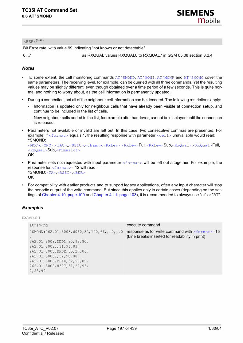
TC35i AT Command Set8.6 AT^SMOND s
mobile
Bit Error rate, with value 99 indicating "not known or not detectable"
0...7 as RXQUAL values RXQUAL0 to RXQUAL7 in GSM 05.08 section 8.2.4
Notes
• To some extent, the cell monitoring commands AT^SMOND, AT^MONI, AT^MONP and AT^SMONC cover thesame parameters. The receiving level, for example, can be queried with all three commands. Yet the resultingvalues may be slightly different, even though obtained over a time period of a few seconds. This is quite nor-mal and nothing to worry about, as the cell information is permanently updated.
• During a connection, not all of the neighbour cell information can be decoded. The following restrictions apply: - Information is updated only for neighbour cells that have already been visible at connection setup, and
continue to be included in the list of cells. - New neighbour cells added to the list, for example after handover, cannot be displayed until the connection
is released.
• Parameters not available or invalid are left out. In this case, two consecutive commas are presented. Forexample, if <format> equals 1, the resulting response with parameter <cell> unavailable would read:^SMOND:<MCC>,<MNC>,<LAC>,,<BSIC>,<chann>,<RxLev>,<RxLev>Full,<RxLev>Sub,<RxQual>,<RxQual>Full,<RxQual>Sub,<Timeslot>OK
• Parameter sets not requested with input parameter <format> will be left out altogether. For example, theresponse for <format>= 12 will read: ^SMOND:<TA>,<RSSI>,<BER>OK
• For compatibility with earlier products and to support legacy applications, often any input character will stopthe periodic output of the write command. But since this applies only in certain cases (depending on the set-tings of Chapter 4.10, page 100 and Chapter 4.11, page 103), it is recommended to always use "at" or "AT".
Examples
EXAMPLE 1
<BER>(num)
at^smond execute command ^SMOND:262,01,3008,6060,32,100,66,,,0,,,0,262,01,3008,DDD1,35,92,80,262,01,3008,,31,96,83,262,01,3008,BFBE,35,27,86,262,01,3008,,32,98,88,262,01,3008,BB44,32,90,89,262,01,3008,8307,31,22,93,2,23,99
response as for write command with <format>=15(Line breaks inserted for readability in print)
TC35i_ATC_V02.07 Page 197 of 439 1/30/04Confidential / Released

TC35i AT Command Set8.6 AT^SMOND s
mobile
EXAMPLE 2
at^smond=1 write command <period>= 1: wait 1 second between consecutive output lines. <format> is assumed 15 (full output) by default
^SMOND:262,01,3008,6060,32,100,66,,,0,,,0,262,01,3008,DDD1,35,92,80,262,01,3008,,31,96,81,262,01,3008,BFBE,35,27,85,262,01,3008,,32,98,87,262,01,3008,BB44,32,90,87,262,01,3008,8307,31,22,93,2,23,99
(Line breaks inserted for readability in print)
Wait 15s for next output line ^SMOND:262,01,3008,6060,32,100,66,,,0,,,0,262,01,3008,DDD1,35,92,81,262,01,3008,,31,96,83,262,01,3008,BFBE,35,27,84,262,01,3008,,32,98,87,262,01,3008,BB44,32,90,91,262,01,3008,8307,31,22,93,2,23,99
(Line breaks inserted for readability in print)
Wait 15s for next output line ^SMOND:262,01,3008,6060,32,100,67,,,0,,,0,262,01,3008,DDD1,35,92,81,262,01,3008,,31,96,82,262,01,3008,BFBE,35,27,85,262,01,3008,,32,98,89,262,01,3008,BB44,32,90,91,262,01,3008,8307,31,22,93,2,23,99
(Line breaks inserted for readability in print)
stop the output by sending a character over the serial interface
OK write command terminated successfully
at^smond=240,5 <period>= 240 Wait 4 minutes before the output of each new line.
^SMOND:262,01,3008,6060,32,100,68,,,0,,,0,2
<format>= 5 indicates only serving cell information <sci> and Timing Advance <TA> are requested. stop the output by sending a character over the serial interface
OK write command terminated successfully
TC35i_ATC_V02.07 Page 198 of 439 1/30/04Confidential / Released

TC35i AT Command Set8.7 AT^MONI s
mobile
8.7 AT^MONI Monitor idle mode and dedicated mode
Syntax
Command Description
The execute command can be used to retrieve the cell parameters of the serving/dedicated cell on request.
The write command can be used to retrieve information of the serving/dedicated cell automatically every<period> seconds. To stop the presentation type "AT" or "at".
Parameter Description
Display period in seconds
1...254
Notes
• The two header lines (see 8.7.1) are output after every ten data lines.
Test Command
AT^MONI=?
Response(s)
^MONI:(list of supported <period>s) OK
Exec Command
AT^MONI
Response(s)
See: 8.7.1OK
Write Command
AT^MONI=<period>
Response(s)
See: 8.7.1OK
PIN ASC0 MUX1 MUX2 MUX3
� � � � �
Reference(s)
SIEMENS
<period>(num)
TC35i_ATC_V02.07 Page 199 of 439 1/30/04Confidential / Released

TC35i AT Command Set8.7 AT^MONI s
mobile
• The length of following output lines exceeds 80 characters. Therefore a terminal program may draw a carriagereturn on a screen. However, this is not part of the response.
8.7.1 AT^MONI responsesME is not connected:a) ME is camping on a cell and registered to the network:
b) ME is camping on a cell but not registered to the network (only emergency call allowed):
c) ME camping on a cell, but searching for a better cell (cell reselection):
d) ME is searching and could not (yet) find a suitable cell:
ME is connected (Call in progress):
Columns for Serving Cell:
Serving Cell I Dedicated channel
chann rs dBm PLMN LAC cell NCC BCC PWR RXLev C1 I chann TS timAdv PWR dBm Q ChMod
1013 21 -71 00101 1001 0103 7 7 33 -105 33 I No connection
Serving Cell I Dedicated channel
chann rs dBm PLMN LAC cell NCC BCC PWR RXLev C1 I chann TS timAdv PWR dBm Q ChMod
1013 21 -71 00101 1001 0103 7 7 33 -105 33 I Limited Service
Serving Cell I Dedicated channel
chann rs dBm PLMN LAC cell NCC BCC PWR RXLev C1 I chann TS timAdv PWR dBm Q ChMod
1013 21 -71 00101 1001 0103 7 7 33 -105 33 I Cell Reselection
Serving Cell I Dedicated channel
chann rs dBm PLMN LAC cell NCC BCC PWR RXLev C1 I chann TS timAdv PWR dBm Q ChMod
Searching
Serving Cell I Dedicated channel
chann rs dBm PLMN LAC cell NCC BCC PWR RXLev C1 I chann TS timAdv PWR dBm Q ChMod
1013 19 -76 00101 1001 0103 7 7 33 -105 33 I 1015 1 0 5 -76 0 S_HR
Column Description
chann ARFCN (Absolute Frequency Channel Number) of the BCCH carrier
rs RSSI value 0 - 63 (RSSI = Received signal strength indication)
dBm receiving level of the BCCH carrier in dBm
PLMN PLMN ID code
LAC location area code, see note below
cell cell ID, see note below
NCC PLMN colour code
BCC base station colour code
TC35i_ATC_V02.07 Page 200 of 439 1/30/04Confidential / Released

TC35i AT Command Set8.7 AT^MONI s
mobile
Columns for Dedicated channel:
8.7.2 Service statesDepending on the service state, an additional textual output is generated (refer also to the response examples):
• 'Searching' - The MS is searching, but could not (yet) find a suitable cell. This output appears after restart ofthe MS or after loss of coverage.
• 'No connection' - The MS is camping on a cell and registered to the network. The service state is 'idle', i.e.there is no connection established or a dedicated channel in use.
• 'Cell Reselection' - The MS has not yet lost coverage but is searching for a better cell, since the cell reselec-tion criterion is fulfilled.
• 'Limited Service' - The MS is camping on a cell but not registered to the network. Only emergency calls areallowed. The MS enters this state, for example, when - no SIM card is inserted, or PIN has not been given, - neither Home PLMN nor any other allowed PLMN are found, - registration request was not answered or denied by the network (use command AT+CREG to query the
registration status), - authentication failed.
8.7.3 Notes• The parameters LAC and cell are presented as hexadecimal digits, the remaining parameters are composed
of decimal digits.• If the radio cell changes during a connection, the parameters PWR, RXLev and C1 of the 'Serving Cell' part
cannot be updated under certain conditions and therefore, are displayed as "-" (for conditions see alsoAT+CREG). This is because the MS does not update the cell selection and reselection parameters since, inthis mode, they are not relevant for operation. When the connection ends, and the mobile is back to IDLEmode, correct values will be given.If the radio cell changes during a connection, it normally takes 1 or 2 seconds to update the parameters cell,
PWR maximal power level used on RACH channel in dBm
RXLev minimal receiving level (in dBm) to allow registration
C1 coefficient for base station selection
Column Description
chann ARFCN (Absolute Frequency Channel Number) of the TCH carrierNote: <chann> = h indicates frequency hopping.
TS timeslot number
timAdv timing advance in bits
PWR current power level
dBm receiving level of the traffic channel carrier in dBm
Q receiving quality (0-7)
ChMod channel mode (S_HR: Half rate, S_FR: Full rate, S_EFR: Enhanced Full Rate)
Column Description
TC35i_ATC_V02.07 Page 201 of 439 1/30/04Confidential / Released

TC35i AT Command Set8.7 AT^MONI s
mobile
NCC and BCC. Until the information is received from the new base station, the default values will be showninstead: cell="0000", NCC="-", BCC="-".
• If the BS supports frequency hopping during a connection, the dedicated channel (parameter chann) is notstable. This mode is indicated by chann = 'h'.
• To some extent, the cell monitoring command AT^SMONC covers the same parameters. The receiving level,for example, can be queried with both commands. Yet the resulting values may be slightly different, eventhough obtained over a time period of a few seconds. This is quite normal and nothing to worry about, as thecell information is permanently updated.
• for compatibility with earlier products and to support legacy applications, any input character may be used tostop the output in certain cases (depending on the settings of Chapter 4.10, page 100 and Chapter 4.11, page103).
TC35i_ATC_V02.07 Page 202 of 439 1/30/04Confidential / Released

TC35i AT Command Set8.8 AT^MONP s
mobile
8.8 AT^MONP Monitor neighbour cells
Syntax
Command Description
This command can be used to obtain information of up to six neighbour cells on request.
This command can be used to retrieve information of up to six neighbour cells automatically every n seconds.To stop the presentation type "at" or "AT".
Parameter Description
Display period in seconds
1...254
Note
• Due to the fact that not all necessary information of the neighbour cells can be decoded during a connection,
Test Command
AT^MONP=?
Response(s)
^MONP:(list of supported <period>s) OK
Exec Command
AT^MONP
Response(s)
See: 8.8.1OK
Write Command
AT^MONP=<period>
Response(s)
See: 8.8.1OK
PIN ASC0 MUX1 MUX2 MUX3
� � � � �
Reference(s)
SIEMENS
<period>(num)
TC35i_ATC_V02.07 Page 203 of 439 1/30/04Confidential / Released

TC35i AT Command Set8.8 AT^MONP s
mobile
there are several constraints to be considered: - Only neighbour cells that have already been visible in IDLE mode will be further updated, as long as they
are still included in the list.- Though new neighbour cells can be added to the list (e.g. due to handover), their C1 and C2 parameters
cannot be displayed until the connection is released. In this case "-" is presented for C1 and C2.- To some extent, the cell monitoring command AT^SMONC covers the same parameters. The receiving
level, for example, can be queried with both commands. Yet the resulting values may be slightly different,even though obtained over a time period of a few seconds. This is quite normal and nothing to worry about,as the cell information is permanently updated.
- For compatibility with earlier products and to support legacy applications, any input character may be usedto stop the output in certain cases (depending on the settings of Chapter 4.10, page 100 and Chapter 4.11,page 103).
8.8.1 AT^MONP responsesResponse of AT^MONP (Example):
chann rs dBm MCC MNC BCC C1 C2
653 26 -84 262 07 0 22 22
660 20 -90 262 07 3 16 16
687 19 -91 262 07 1 15 15
678 14 -96 262 07 3 10 10
671 14 -96 262 07 1 10 10
643 10 -100 262 07 7 6 6
Column Description
Chann ARFCN (Absolute Radio Frequency Channel Number) of the BCCH carrier
rs RSSI value 0 - 63 (RSSI = Received signal strength indication)
dBm Receiving level in dBm
MCC Mobile Country Code (first part of the PLMN code)
MNC Mobile Network Code (second part of the PLMN code)
BCC Base Station colour code
C1 cell selection criterion
C2 cell reselection criterion
TC35i_ATC_V02.07 Page 204 of 439 1/30/04Confidential / Released

TC35i AT Command Set8.9 AT^SALS s
mobile
8.9 AT^SALS Alternate Line Service
The AT^SALS command is designed to support Alternate Line Service. This allows the subscriber to use twovoice numbers on the same SIM card (service requires a dual line SIM card).
Syntax
Unsolicited Result Code
If switched on with <view>=1: ^SALS: <line>
Indicates the line used by an incoming call.
Command Description
The read command returns the presentation mode of <view> and the currently selected <line>.
Test Command
AT^SALS=?
Response(s)
^SALS:possible status of <view>s), (list of supported <line>s)
OK
Read Command
AT^SALS?
Response(s)
^SALS: presentation mode of <view>, current <line>
OKERROR
Write Command
AT^SALS=<view> [, <line>]
Response(s)
OKERROR
PIN ASC0 MUX1 MUX2 MUX3
� � � � �
Reference(s)
SIEMENS
TC35i_ATC_V02.07 Page 205 of 439 1/30/04Confidential / Released

TC35i AT Command Set8.9 AT^SALS s
mobile
The write command enables or disables the presentation mode of <view> and selects the preferred <line>.
Parameter Description
Controls the presentation mode of the URC "^SALS" which indicates the line number used by an incoming call:
0(&F) Disables indication of the called line
1 Enables indication of the called line
Selects the line to be used for outgoing calls.
[1] ALS Line 1
2 ALS Line 2
Notes
• The selected <line> will be saved at non-volatile Flash memory and thus retained after Power Down.
• The <line> will be reset by AT&F and ATZ and afterwards saved at non-volatile memory too.
• The <view> will be reset after Power Down as well as by ATZ or AT&F.
• If a non ALS SIM is inserted, the <line> will be reset to line 1 as well.
Example
<view>(num)
<line>(num)
AT^SALS=1,1 Line 1 has been selected for outgoing calls. "^SALS" URC is enabled.RING You receive a notification that you have an incoming call on line 2.^SALS: 2
TC35i_ATC_V02.07 Page 206 of 439 1/30/04Confidential / Released

TC35i AT Command Set8.10 AT^SHOM s
mobile
8.10 AT^SHOM Display Homezone
Syntax
Command Description
TA returns homezone state. Result is valid only, if network registration state <stat> is 1 (registered) (seeAT+CREG). Feature is available only for supported network operators (Viag, One2One, Orange and LCI) and requires a suit-able SIM card. If the homezone feature is not supported by the network operator or SIM card, result is always 0.
Parameter Description
0 ME is out of Homezone
1 ME is within the Homezone
Test Command
AT^SHOM=?
Response(s)
OK
Exec Command
AT^SHOM
Response(s)
^SHOM: <homezonestate>OKERROR+CME ERROR: <err>
PIN ASC0 MUX1 MUX2 MUX3
� � � � �
Reference(s)
SIEMENS
<homezonestate>(num)
TC35i_ATC_V02.07 Page 207 of 439 1/30/04Confidential / Released

TC35i AT Command Set8.11 AT^SPLM s
mobile
8.11 AT^SPLM Read the PLMN list
Syntax
Command Description
TA returns the list of operator names from the ME. Each operator code <numeric> that has an alphanumericequivalent <alpha> in the ME memory is returned.
Parameter Description
Operator in numeric form; GSM location area identification number
Operator in long alphanumeric format; can contain up to 16 characters
Note
• See also GSM 07.07: AT+COPN, AT+COPS
Test Command
AT^SPLM=?
Response(s)
OKERROR+CME ERROR: <err>
Exec Command
AT^SPLM
Response(s)
^SPLM:<numeric>, long <alpha> [... ]OKERROR+CME ERROR
PIN ASC0 MUX1 MUX2 MUX3
� � � � �
Reference(s)
SIEMENS
<numeric>(str)
<alpha>(str)
TC35i_ATC_V02.07 Page 208 of 439 1/30/04Confidential / Released

TC35i AT Command Set8.12 AT^SPLR s
mobile
8.12 AT^SPLR Read entry from the preferred operators list
Syntax
Command Description
Test command returns the whole index range supported by the SIM
Write command returns used entries from the SIM list of preferred operators with <indexa> between <index1>and <index2>. If <index2> is not given, only entry with <index1> is returned.
Parameter Description
location number to read from
location number to read to
index range / index out of the range supported by the SIM between <index1> and <index2>
Test Command
AT^SPLR=?
Response(s)
^SPLR:(list of supported) <indexa>s OKERROR+CME ERROR: <err>
Write Command
AT^SPLR=<index1>[, <index2>]
Response(s)
^SPLR: <index1><oper> ^SPLR: <index2><oper> OKERROR+CME ERROR: <err>
PIN ASC0 MUX1 MUX2 MUX3
� � � � �
Reference(s)
SIEMENS
<index1>(num)
<index2>(num)
<indexa>(num)
TC35i_ATC_V02.07 Page 209 of 439 1/30/04Confidential / Released

TC35i AT Command Set8.12 AT^SPLR s
mobile
operator in numeric form; GSM location area identification number
Note
• See also GSM 07.07: AT+CPOL
<oper>(str)
TC35i_ATC_V02.07 Page 210 of 439 1/30/04Confidential / Released

TC35i AT Command Set8.13 AT^SPLW s
mobile
8.13 AT^SPLW Write an entry to the preferred operators list
Syntax
Command Description
Test command returns the whole index range supported by the SIM
Write command writes an entry to the SIM list of preferred operators at location number <index>. If <index>is given but <oper> is left out, the entry is deleted. If <oper> is given but <index> is left out, <oper> is insertedin the next free location.
Parameter Description
location number
Operator in numeric format (GSM Location Area Identification number which consists of a 3-digit country codeplus a 2- or 3-digit network code).
Note
• See also GSM 07.07: AT+CPOL
Test Command
AT^SPLW=?
Response(s)
^SPLW:(list of supported) <index>s OKERROR+CME ERROR:
Write Command
AT^SPLW=<index>[, <oper>]
Response(s)
OKERROR+CME ERROR: <err>
PIN ASC0 MUX1 MUX2 MUX3
� � � � �
Reference(s)
SIEMENS
<index>(num)
<oper>(str)
TC35i_ATC_V02.07 Page 211 of 439 1/30/04Confidential / Released
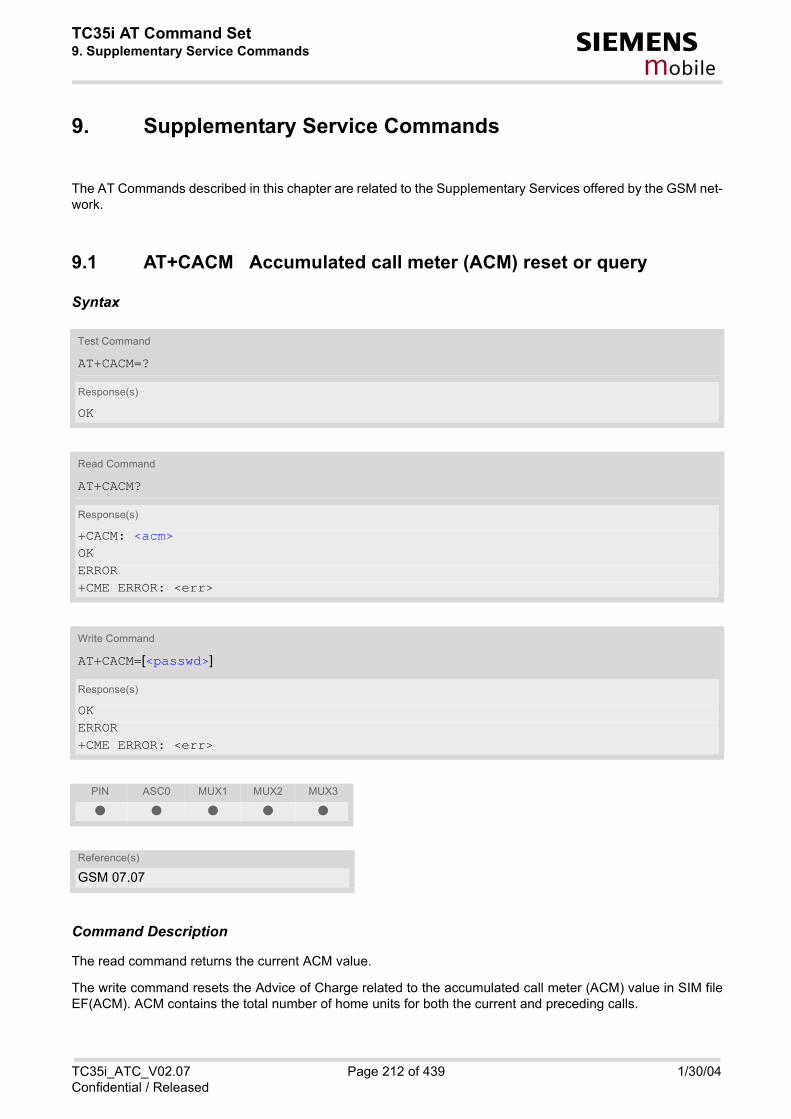
TC35i AT Command Set9. Supplementary Service Commands s
mobile
9. Supplementary Service Commands
The AT Commands described in this chapter are related to the Supplementary Services offered by the GSM net-work.
9.1 AT+CACM Accumulated call meter (ACM) reset or query
Syntax
Command Description
The read command returns the current ACM value.
The write command resets the Advice of Charge related to the accumulated call meter (ACM) value in SIM fileEF(ACM). ACM contains the total number of home units for both the current and preceding calls.
Test Command
AT+CACM=?
Response(s)
OK
Read Command
AT+CACM?
Response(s)
+CACM: <acm> OKERROR+CME ERROR: <err>
Write Command
AT+CACM=[<passwd>]
Response(s)
OKERROR+CME ERROR: <err>
PIN ASC0 MUX1 MUX2 MUX3
� � � � �
Reference(s)
GSM 07.07
TC35i_ATC_V02.07 Page 212 of 439 1/30/04Confidential / Released

TC35i AT Command Set9.1 AT+CACM s
mobile
Parameter Description
Three bytes of the current ACM value in hexadecimal format (e.g. "00001E" indicates decimal value 30) 000000- FFFFFF.
SIM PIN2
<acm>(str)
<passwd>(str)
TC35i_ATC_V02.07 Page 213 of 439 1/30/04Confidential / Released

TC35i AT Command Set9.2 AT^SACM s
mobile
9.2 AT^SACM Advice of charge and query of ACM and ACMmax
Syntax
Unsolicited Result Code
+CCCM: <ccm>
When activated, an unsolicited result code is sent when the CCM value changes, but not more often than every10 seconds.
Command Description
The execute command can be used to query the current mode of the Advice of Charge supplementary service,the SIM values of the accumulated call meter (ACM) and accumulated call meter maximum (ACMmax).
The write command enables or disables the presentation of unsolicited result codes to report the call charges.
Test Command
AT^SACM=?
Response(s)
^SACM:(list of supported <n>s) OK
Exec Command
AT^SACM
Response(s)
^SACM: <n>, <acm>, <acmMax> OKERROR+CME ERROR: <err>
Write Command
AT^SACM=<n>
Response(s)
OKERROR+CME ERROR: <err>
PIN ASC0 MUX1 MUX2 MUX3
� � � � �
Reference(s)
SIEMENS
TC35i_ATC_V02.07 Page 214 of 439 1/30/04Confidential / Released

TC35i AT Command Set9.2 AT^SACM s
mobile
Parameter Description
[0](&F) suppress unsolicited result code
1 display unsolicited result code
Three bytes of the current ACM value in hexadecimal format (e.g. "00001E" indicates decimal value 30) 000000-FFFFFF
Three bytes of the max. ACM value in hexadecimal format (e.g. "00001E" indicates decimal value 30) 000000disable ACMmax feature 000001-FFFFFF
Three bytes of the current CCM value in hexadecimal format (e.g. "00001E" indicates decimal value 30); bytesare coded in the same way as ACMmax value in the SIM 000000-FFFFFF
Notes
• When you power down or reset the ME with AT+CFUN=1,1 the URC presentation mode will be reset to itsdefault. To benefit from the URC it is recommended to have the setting included in the user profile saved withAT&W, or to select <n>=1 every time you reboot the ME.
• See also GSM07.07: AT+CACM, AT+CAMM, AT+CAOC.
<n>(num)(&W)(&V)
<acm>(str)(&V)
<acmMax>(str)(&V)
<ccm>(str)
TC35i_ATC_V02.07 Page 215 of 439 1/30/04Confidential / Released

TC35i AT Command Set9.3 AT+CAMM s
mobile
9.3 AT+CAMM Accumulated call meter maximum (ACMmax) set or query
Syntax
Command Description
The read command returns the current ACMmax value.
The write command sets the Advice of Charge related to the accumulated call meter maximum value in SIM fileEF (ACMmax). ACMmax contains the maximum number of home units allowed to be consumed by the sub-scriber.
Parameter Description
Three bytes of the max. ACM value in hexadecimal format (e.g. "00001E" indicates decimal value 30) 000000disable ACMmax feature 000001-FFFFFF.
Test Command
AT+CAMM=?
Response(s)
OK
Read Command
AT+CAMM?
Response(s)
+CAMM: <acmmax> OKERROR+CME ERROR: <err>
Write Command
AT+CAMM=[<acmmax>[, <passwd>]]
Response(s)
OKERROR+CME ERROR: <err>
PIN ASC0 MUX1 MUX2 MUX3
� � � � �
Reference(s)
GSM 07.07
<acmmax>(str)
TC35i_ATC_V02.07 Page 216 of 439 1/30/04Confidential / Released

TC35i AT Command Set9.3 AT+CAMM s
mobile
SIM PIN2 <passwd>(str)
TC35i_ATC_V02.07 Page 217 of 439 1/30/04Confidential / Released
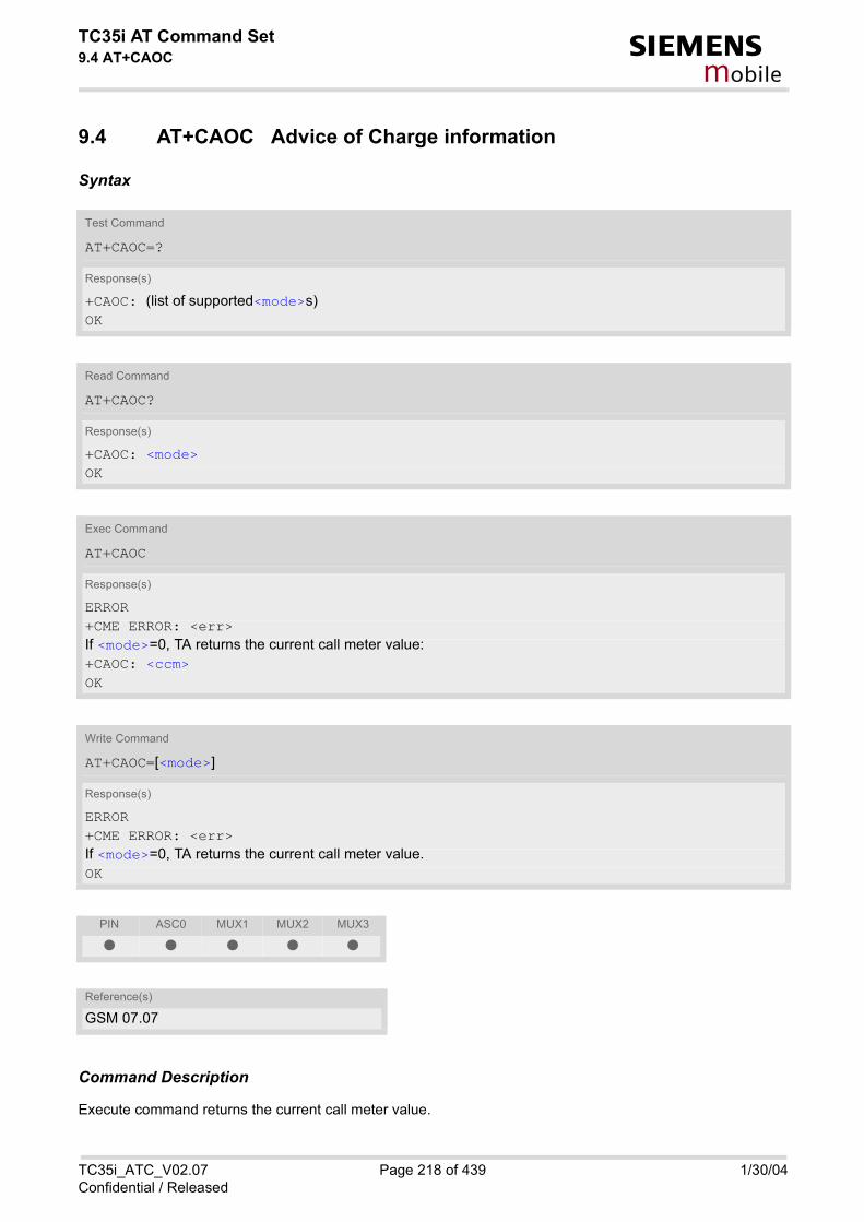
TC35i AT Command Set9.4 AT+CAOC s
mobile
9.4 AT+CAOC Advice of Charge information
Syntax
Command Description
Execute command returns the current call meter value.
Test Command
AT+CAOC=?
Response(s)
+CAOC: (list of supported<mode>s) OK
Read Command
AT+CAOC?
Response(s)
+CAOC: <mode> OK
Exec Command
AT+CAOC
Response(s)
ERROR+CME ERROR: <err>If <mode>=0, TA returns the current call meter value:+CAOC: <ccm>OK
Write Command
AT+CAOC=[<mode>]
Response(s)
ERROR+CME ERROR: <err>If <mode>=0, TA returns the current call meter value.OK
PIN ASC0 MUX1 MUX2 MUX3
� � � � �
Reference(s)
GSM 07.07
TC35i_ATC_V02.07 Page 218 of 439 1/30/04Confidential / Released

TC35i AT Command Set9.4 AT+CAOC s
mobile
The write command sets the Advice of Charge supplementary service function mode.
Parameter Description
0 query CCM value
Three bytes of the current CCM value in hexadecimal format (e.g. "00001E" indicates decimal value 30); bytesare similarly coded as ACMmax value in the SIM 000000-FFFFFF.
<mode>(num)(&V)
<ccm>(str)
TC35i_ATC_V02.07 Page 219 of 439 1/30/04Confidential / Released

TC35i AT Command Set9.5 AT+CCUG s
mobile
9.5 AT+CCUG Closed User Group
Syntax
Command Description
The Test command returns the supported parameters.
The Read command returns if the Explicit CUG invocation is activated (in parameter <n>), which CUG <index>is chosen, and if Preferential Group or Outgoing Access is suppressed (in parameter <info>).
The write command serves to activate or deactivate the explicit CUG invocation, to set the desired index, and tospecify if Preferential Group or Outgoing Access shall be suppressed.
Test Command
AT+CCUG=?
Response(s)
+CCUG:list of supported <n>, range of supported <index>, range of supported <info> OKERROR+CME ERROR
Read Command
AT+CCUG?
Response(s)
+CCUG:<n>, <index>, <info> OKERROR+CME ERROR
Write Command
AT+CCUG=[[<n>][, <index>][, <info>]]
Response(s)
OKERROR+CME ERROR
PIN ASC0 MUX1 MUX2 MUX3
� � � � �
Reference(s)
GSM 07.07, GSM 02.85, GSM 03.85, GSM 04.85
TC35i_ATC_V02.07 Page 220 of 439 1/30/04Confidential / Released

TC35i AT Command Set9.5 AT+CCUG s
mobile
Parameter Description
explicit CUG invocation options
0(D) Deactivate explicit CUG invocation
1 Activate explicit CUG invocation
0-9 explicit selection of CUG index
10(D) No index (preferred CUG taken from subscriber data)
state of the call
0(D) no information
1 suppress outgoing access
2 suppress preferential CUG
3 Suppress preferential CUG and Outgoing Access.
Notes
• The active settings for omitted parameters are retained without changes.
• Explicit CUG invocation means that at each call setup, CUG information is added to the called number.
• Upon delivery, settings are predefined with <n>=0, <index>=10, <info>=0. These delivery defaults cannot be recalled automatically.
• When starting a call with ATD, Parameter 'G' or 'g' of command ATD will have no effect if the option selectedfor this single call is identical to the option already selected with AT+CCUG.
• Current settings are saved in the ME automatically.
• ATZ or AT&F do not influence the current settings.
• some combinations of parameters may lead to rejection of CUG calls by the network. For more information,please consult GSM 04.85
<n>(num)
<index>(num)
<info>(num)
TC35i_ATC_V02.07 Page 221 of 439 1/30/04Confidential / Released

TC35i AT Command Set9.6 AT+CCFC s
mobile
9.6 AT+CCFC Call forwarding number and conditions control
Syntax
Command Description
The Test command returns the supported parameters.
The write command controls the call forwarding supplementary service. Registration, erasure, activation, deac-tivation and status query are supported.
Parameter Description
reason for call forwarding
0 unconditional
1 mobile busy
2 no reply
Test Command
AT+CCFC=?
Response(s)
+CCFC:(list/range of supported <reason>s) OK
Write Command
AT+CCFC=<reason>, <mode> [, <number>[, <type>[, <class>[, <time>]]]]
Response(s)
if <mode> is not equal 2 and command successful: OKif <mode>= 2, <reason> is not equal 2 and command successful: +CCFC: <status>, <class> [, <number>, <type>] OKif <mode>= 2, <reason>= 2 and command successful: +CCFC: <status>, <class> [, <number>, <type>, <time>] OKIf error is related to ME functionality +CME ERROR
PIN ASC0 MUX1 MUX2 MUX3
� � � � �
Reference(s)
GSM 07.07, GSM 02.04, GSM 02.82, GSM 03.82, GSM 04.82
<reason>(num)
TC35i_ATC_V02.07 Page 222 of 439 1/30/04Confidential / Released

TC35i AT Command Set9.6 AT+CCFC s
mobile
3 not reachable
4 all call forwarding (includes reasons 0, 1, 2 and 3)
5 all conditional call forwarding (includes reasons 1, 2 and 3)
network operation to be performed for Supplementary service "call forwarding"
0 disable call forwarding (disable service)
1 enable call forwarding (enable service)
2 query status of call forwarding (query service status)
3 register <number> and activate call forwarding (register service)
4 erase <number> and deactivate call forwarding (erase service)
string type phone number of forwarding address in format specified by <type>. If you select <mode>= 3, thephone <number> will be registered in the network. This allows you to disable / enable CF to the same destinationwithout the need to enter the phone number once again. Depending on the services offered by the provider theregistration may be mandatory before CF can be used. The number remains registered in the network until youregister another number or erase it using <mode> = 4.
type of address octect
145 dialling string <number> includes international access code character '+'
129 otherwise
integer or sum of integers each representing a class of information, i.e. a bearer service, telecommunication ser-vice or bearer service group as defined in "GSM 02.04"
1 voice
2 data<class> 2 (data) comprises all those <class> values between 16 and 128, thatare supported both by the network and the MS. This means, a setting made for<class> 2 applies to all remaining data classes (if supported). In addition, youcan assign a different setting to a specific class. For example, you can activateCall Forwarding for all data classes, but deactivate it for a specific data class.
4 fax
8 SMS
16 data circuit sync
32 data circuit async
64 dedicated packet access
128 dedicated PAD access
1...[7]...255 combination of some of the above classes. For example, the default setting 7represents the sum of the integers 1, 2 and 4 (CF for voice, data and fax). Thevalue 255 covers all classes. If the <class> parameter is omitted, the defaultvalue 7 is used.
<mode>(num)
<number>(str)
<type>(num)
<class>(num)
TC35i_ATC_V02.07 Page 223 of 439 1/30/04Confidential / Released

TC35i AT Command Set9.6 AT+CCFC s
mobile
5...[20]...30 time to wait before call is forwarded, rounded to a multiple of 5 sec. (only for<reason>=no reply)
0 Call Forwarding not active
1 Call Forwarding active
Notes
• You can register, disable, enable and erase <reason> 4 and 5 as described above. However, querying thestatus of <reason> 4 and 5 with AT+CCFC will result in an error ("CME error: Operation not supported"). Asan alternative, you may use the ATD command followed by *'# codes to check the status of these two reasons.See List of *# Codes for a complete list of *# GSM codes. See also examples below.
• Most networks will not permit registration of new parameters for conditional call forwarding (reasons 1,2,3,5)while unconditional call forwarding is enabled.
• The AT+CCFC command offers a broad range of call forwarding options according to the GSM specifications.However, when you attempt to set a call forwarding option which is not provisioned or not yet subscribed to,the setting will not take effect regardless of the response returned. The responses in these cases vary withthe network (for example "OK", "Operation not allowed", "Operation not supported" etc.). To make sure checkthe call forwarding status with <mode>=2.
• Some networks may choose to have certain call forwarding condtions permanently enabled (e.g. forwardingto a mailbox if the mobile is not reachable). In this case, erasure or deactivation of call forwarding for theseconditions will not be successful, even if the CCFC request is answered with response "OK".
• The command has been implemented with the full set of <class> parameters according to GSM 07.07. Foractual applicability of SS "call forwarding" to a specific service or service group (a specific <class> value)please consult table A.1 of GSM 02.04.
• there is currently no release of GSM standard "GSM 02.04", in which the "Call Forwarding" SupplementaryService is defined as applicable to SMS services
Example
Please note that when you configure or query call forwarding without specifying any classes, the settings willrefer to classes 1, 2 and 4 only (=default). The handling of classes is equivalent to AT+CLCK.
• To register the destination number for unconditional call forwarding (CFU):
The destination number will be registered for voice, data and fax services (default <class> 7).In most networks, the registration will also cause call forwarding to be activated for these <class> values.
• To query the status of CFU without specifying <class>:
<time>(num)
<status>(num)
at+ccfc=0,3,"+493012345678",145
OK
at+ccfc=0,2
+CCFC: 1,1,"+493012345678",145
+CCFC: 1,2,"+493012345678",145
+CCFC: 1,4,"+493012345678",145
OK
TC35i_ATC_V02.07 Page 224 of 439 1/30/04Confidential / Released

TC35i AT Command Set9.6 AT+CCFC s
mobile
• To deactivate CFU without specifying <class>:
To check whether CFU was successfully deactivated (note that the destination number remains registered inthe network when you disable CFU):
• To erase the registered CFU destination number:
Now, when you check the status, no destination number will be indicated:
• To query the status of CFU for all classes:
• <reason> 4 or 5 cannot be used to query the status of all call forwarding reasons (see also notes above):
at+ccfc=0,0
OK
at+ccfc=0,2
+CCFC: 0,1,"+493012345678",145
+CCFC: 0,2,"+493012345678",145
+CCFC: 0,4,"+493012345678",145
OK
at+ccfc=0,4
OK
at+ccfc=0,2
+CCFC: 0,1
+CCFC: 0,2
+CCFC: 0,4
OK
at+ccfc=0,2,,,255
+CCFC: 0,1
+CCFC: 0,2
+CCFC: 0,4
+CCFC: 0,8
+CCFC: 0,16
+CCFC: 0,32
+CCFC: 0,64
+CCFC: 0,128
OK
at+ccfc=4,2
+CME error: operation not supported
at+ccfc=5,2
+CME error: operation not supported
TC35i_ATC_V02.07 Page 225 of 439 1/30/04Confidential / Released

TC35i AT Command Set9.7 AT+CCWA s
mobile
9.7 AT+CCWA Call Waiting
This command controls the "Call Waiting" supplementary service according to GSM 02.83. Activation, deactiva-tion and status query are supported.
Syntax
Unsolicited Result Codes
URC 1
Indication of a call that is currently waiting and can be accepted.
Test Command
AT+CCWA=?
Response(s)
+CCWA:(list of supported <n>s) OK
Read Command
AT+CCWA?
Response(s)
+CCWA:<n> OK
Write Command
AT+CCWA=[[<n>][, <mode>][, <class>]]
Response(s)
if <mode> is not equal 2 and command successful: OKif <mode>= 2 and command successful: +CCWA: <status>, <class> [+CCWA: <status>, <class> ][+CCWA: ...]OKIf error is related to ME functionality +CME ERROR
PIN ASC0 MUX1 MUX2 MUX3
� � � � �
Reference(s)
GSM 07.07, GSM 02.04, GSM 02.83, GSM 03.83, GSM 04.83
TC35i_ATC_V02.07 Page 226 of 439 1/30/04Confidential / Released

TC35i AT Command Set9.7 AT+CCWA s
mobile
+CCWA: <calling number>, <type of number>, <class>, , <CLI validity>
If <n>=1 and the call waiting supplementary service is enabled in the network, URC "+CCWA" indicates a wait-ing call to the TE. It appears while the waiting call is still ringing.
URC 2
Indication of a call that has been waiting.
^SCWA
If <n>=1 and the call waiting supplementary service is enabled in the network, this URC indicates that a wait-ing call rang when the ME was in online mode during a CSD call, but the calling party hung up before the MEwent back to command mode.
Command Description
The test command returns the list of supported "<n>"s.
The read command returns the current value of parameter <n>.
The write command controls the call waiting supplementary service. Activation, deactivation and status queryare supported.
Parameter Description
Switch URCs "+CCWA" and "^SCWA" for call waiting on/off
0 Disable display of URCs "+CCWA" and "^SCWA"
1 Enable display of URCs "+CCWA" and "^SCWA"
Network operation to be performed for Supplementary service call waiting
0 Disable call waiting (disable service)
1 Enable call waiting (enable service)
2 Query status of call waiting (query service status)
Integer or sum of integers each representing a class of information, i.e. a bearer service, telecommunication ser-vice or bearer service group as defined in "GSM 02.04".In the write command, parameter <class> specifies the class of the active call during which an incoming callof any class is to be regarded as a waiting call.In URC "+CCWA: <calling number>, <type of number>, <class>, , <CLI validity>", parameter<class> specifies the class of the waiting call.
1 Voice
2 Data<class> 2 (data) comprises all those <class> values between 16 and 128, thatare supported both by the network and the MS. This means, a setting made for<class> 2 applies to all remaining data classes (if supported). In addition, youcan assign a different setting to a specific class. For example, you can activatecall waiting for all data classes, but deactivate it for a specific data class.
4 Fax
[7] Voice, data and fax (1+2+4)
<n>(num)
<mode>(num)
<class>(num)
TC35i_ATC_V02.07 Page 227 of 439 1/30/04Confidential / Released

TC35i AT Command Set9.7 AT+CCWA s
mobile
8 SMS
16 Data circuit sync
32 Data circuit async
64 Dedicated packet access
128 Dedicated PAD access
1...[7]...255 Combination of some of the above classes. For example, the default setting 7represents the sum of the integers 1, 2 and 4 (CF for voice, data and fax). Thevalue 255 covers all classes. If parameter "class"is omitted, the default value 7is used.
0 Call waiting service is not active
1 Call waiting service is active
Phone number of waiting caller in the format specified by parameter <type of number>.
Type of address octet in integer format (refer to GSM 04.08, subclause 10.5.4.7)
145 <calling number> includes international access code character '+'
129 Otherwise
0 CLI valid
1 CLI has been withheld
2 CLI is not available
Notes
• If the active call is a CSD call, and a waiting call is received, then the ME produces a BREAK while still inonline mode, and displays - the +CCWA URC (as above) when the ME goes back to command mode while the waiting call is still active
and can be accepted; - or the ^SCWA URC (as above) when the ME goes back to command mode after the waiting call has
ended.
• With the AT+CHLD command, it is possible to establish a multiparty call or to set the active voice call on holdand then accept a waiting voice call (not possible with fax and data call). See also AT+CHLD
• Users should be aware that if call waiting is activated (<mode>=1), the presentation of URCs needs to beenabled, too (<n>=1). Otherwise, on the one hand, a waiting caller would be kept waiting due to lack of BUSY signals, while, on theother hand, the waiting call would not be indicated to the called party.
• The AT+CCWA command offers a broad range of options according to the GSM specifications. However,when you attempt to enable call waiting for a <class> for which the service is not provisioned or not sup-ported , the setting will not take effect regardless of the response returned. The responses in these cases varywith the network (for example "OK", "Operation not allowed", "Operation not supported" etc.). To make sure
<status>(num)
<calling number>(str)
<type of number>(num)
<CLI validity>(num)
TC35i_ATC_V02.07 Page 228 of 439 1/30/04Confidential / Released

TC35i AT Command Set9.7 AT+CCWA s
mobile
check the current call waiting settings with <mode>=2.
• The AT+CCWA command has been implemented with the full set of <class> parameters according toGSM 07.07. For actual applicability of SS call waiting to a specific service or service group (a specific<class> value) please consult table A.1 of GSM 02.04
• Despite the specifications stated in GSM 02.04 call waiting is not handled uniformly among all networks: GSM 02.04, Annex A, provides the following specification: "The applicability of call waiting refers to the telecommunication service of the active call and not of the waitingcall. The incoming, waiting, call may be of any kind." Nevertheless, networks do differ on the actual imple-mentation of the service. For example, the activation of call waiting for <class> 4, "fax", causes some net-works to send a call waiting indication if a call "of any kind" comes in during an active fax call, but others may(with the same settings active) indicate a waiting fax call during any kind of active call. Thus, the only reliableway to receive or prevent a call waiting indication under any circumstances and in any network, is to activateor deactivate call waiting for all tele- and bearer services (<class> 255).
Examples
EXAMPLE 1
Parameter <n>
EXAMPLE 2
Parameter <mode>
EXAMPLE 3
Parameter <class>
at+ccwa=1 To enable the presentation of the URC OK
at+ccwa=,1 To activate the supplementary service in the network for voice, data, and fax calls (default classes). Note that Parameter <n> is left out. In this case, the current value of <n> will be retained.
OK
at+ccwa=,2 To query the network status of call waiting for default classes
at+ccwa=1,1 Call Waiting is activated during voice calls. at+ccwa=1,2 Call Waiting is activated during data calls. at+ccwa=1,4 Call Waiting is activated during fax calls. OK
AT+CCWA=,0,1 To deactivate call waiting for voice calls. OK
TC35i_ATC_V02.07 Page 229 of 439 1/30/04Confidential / Released

TC35i AT Command Set9.8 AT+CHLD s
mobile
9.8 AT+CHLD Call Hold and Multiparty
Syntax
Command Description
TA controls the Supplementary Services Call Hold and Multiparty. Calls can be put on hold, recovered, released,and added to a conversation.Like for all Supplementary Services, the availability and detailed functionality of Call Hold and Multiparty servicesdepends on the configuration of the GSM network. The TC35i can only request the service, but the networkdecides whether and how the request will be answered.
Parameter Description
0 Release all held calls or set User Determined User Busy (UDUB) for a waitingcall: • If a call is waiting, release the waiting call. The calling party will receive a
"BUSY" indication (Supplementary Service User Determined User Busy"UDUB")
• Otherwise, terminate all held calls (if any).
1 Terminate all active calls (if any) and accept "the other call" as the active call: • If a call is waiting, the waiting call will be accepted. • Otherwise, if a held call is present, the held call becomes active.
Test Command
AT+CHLD=?
Response(s)
+CHLD: (list of supported <n>s) OK
Write Command
AT+CHLD=[<n>]
Response(s)
OKERROR+CME ERROR: <err>
PIN ASC0 MUX1 MUX2 MUX3
� � � � �
Reference(s)
GSM 07.07
<n>(num)
TC35i_ATC_V02.07 Page 230 of 439 1/30/04Confidential / Released
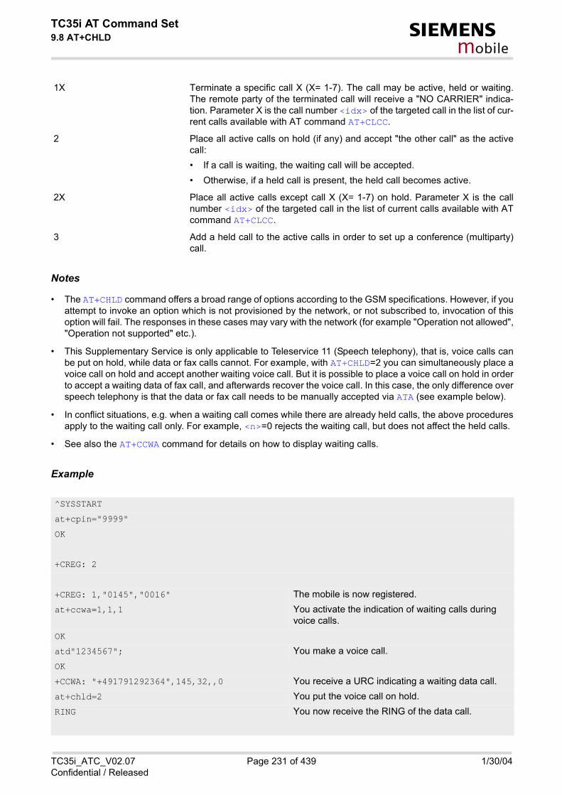
TC35i AT Command Set9.8 AT+CHLD s
mobile
1X Terminate a specific call X (X= 1-7). The call may be active, held or waiting.The remote party of the terminated call will receive a "NO CARRIER" indica-tion. Parameter X is the call number <idx> of the targeted call in the list of cur-rent calls available with AT command AT+CLCC.
2 Place all active calls on hold (if any) and accept "the other call" as the activecall: • If a call is waiting, the waiting call will be accepted. • Otherwise, if a held call is present, the held call becomes active.
2X Place all active calls except call X (X= 1-7) on hold. Parameter X is the callnumber <idx> of the targeted call in the list of current calls available with ATcommand AT+CLCC.
3 Add a held call to the active calls in order to set up a conference (multiparty)call.
Notes
• The AT+CHLD command offers a broad range of options according to the GSM specifications. However, if youattempt to invoke an option which is not provisioned by the network, or not subscribed to, invocation of thisoption will fail. The responses in these cases may vary with the network (for example "Operation not allowed","Operation not supported" etc.).
• This Supplementary Service is only applicable to Teleservice 11 (Speech telephony), that is, voice calls canbe put on hold, while data or fax calls cannot. For example, with AT+CHLD=2 you can simultaneously place avoice call on hold and accept another waiting voice call. But it is possible to place a voice call on hold in orderto accept a waiting data of fax call, and afterwards recover the voice call. In this case, the only difference overspeech telephony is that the data or fax call needs to be manually accepted via ATA (see example below).
• In conflict situations, e.g. when a waiting call comes while there are already held calls, the above proceduresapply to the waiting call only. For example, <n>=0 rejects the waiting call, but does not affect the held calls.
• See also the AT+CCWA command for details on how to display waiting calls.
Example
^SYSSTART
at+cpin="9999"
OK
+CREG: 2
+CREG: 1,"0145","0016" The mobile is now registered.at+ccwa=1,1,1 You activate the indication of waiting calls during
voice calls.OK
atd"1234567"; You make a voice call.OK
+CCWA: "+491791292364",145,32,,0 You receive a URC indicating a waiting data call.at+chld=2 You put the voice call on hold.RING You now receive the RING of the data call.
TC35i_ATC_V02.07 Page 231 of 439 1/30/04Confidential / Released

TC35i AT Command Set9.8 AT+CHLD s
mobile
OK
RING
RING
ATA You accept the data call.CONNECT 9600/RLP
hello
OK
+++ With ''+++'' you go in command mode.at+clcc You interrogate the status of all established calls.+CLCC: 1,0,1,0,0,"03038639268",129
+CLCC: 2,1,0,1,0,"+491791292364",145
OK
at+chld=1 The active data call is terminated and the held voice call becomes active.
OK
at+clcc
+CLCC: 1,0,0,0,0,"03038639268",129
OK
TC35i_ATC_V02.07 Page 232 of 439 1/30/04Confidential / Released

TC35i AT Command Set9.9 AT+CLIP s
mobile
9.9 AT+CLIP Calling line identification presentation
Syntax
Unsolicited Result Codes
URC 1
Voice call response format:
+CLIP: <number>, <type>, , , , <CLI validity>
URC 2
Data/FAX call response format:
+CLIP: <number>, <type>
When CLIP is enabled at the TE (and is permitted by the calling subscriber), an unsolicited result code isreturned after every RING (or +CRING: <type>) at a mobile terminating call.
Test Command
AT+CLIP=?
Response(s)
+CLIP: (list of supported<n>s) OK
Read Command
AT+CLIP?
Response(s)
+CLIP: <n>, <m> OKERROR+CME ERROR: <err>
Write Command
AT+CLIP=<n>
Response(s)
OKERROR+CME ERROR: <err>
PIN ASC0 MUX1 MUX2 MUX3
� � � � �
Reference(s)
GSM 07.07
TC35i_ATC_V02.07 Page 233 of 439 1/30/04Confidential / Released

TC35i AT Command Set9.9 AT+CLIP s
mobile
Command Description
This command refers to the GSM supplementary service CLIP (Calling Line Identification Presentation) thatenables a called subscriber to get the calling line identity (CLI) of the calling party when receiving a mobile ter-minated call.
Write command enables or disables the presentation of the CLI at the TE. It has no effect on the execution of thesupplementary service CLIP in the network.
Parameter Description
[0](&F) suppress unsolicited result codes
1 display unsolicited result codes
0 CLIP not provisioned
1 CLIP provisioned
2 unknown
string type phone number of calling address in format specified by <type>
type of address octet in integer format; 145 when dialling string includes in-ternational access code character"+", otherwise 129.
0 CLI valid
1 CLI has been withheld by the originator.
2 CLI is not available due to interworking problems or limitations of originatingnetwork. <number> shall be an empty string ("") and <type> value will not besignificant.
When CLI is not available ( <CLI validity>=2), <number> shall be an empty string ("") and <type> valuewill not be significant. Nevertheless, TA shall return the recommended value 128 for <type> (TON/NPIunknown in accordance with GSM 04.08 subclause 10.5.4.7). When CLI has been withheld by the originator, (<CLI validity>=1) and the CLIP is provisioned with the"override category" option (refer GSM 02.81 and GSM 03.81), <number> and <type> is provided. Otherwise,TA shall return the same setting for <number> and <type> as if the CLI was not available.
<n>(num)(&W)(&V)
<m>(num)(&V)
<number>(str)
<type>(num)
<CLI validity>(num)
TC35i_ATC_V02.07 Page 234 of 439 1/30/04Confidential / Released
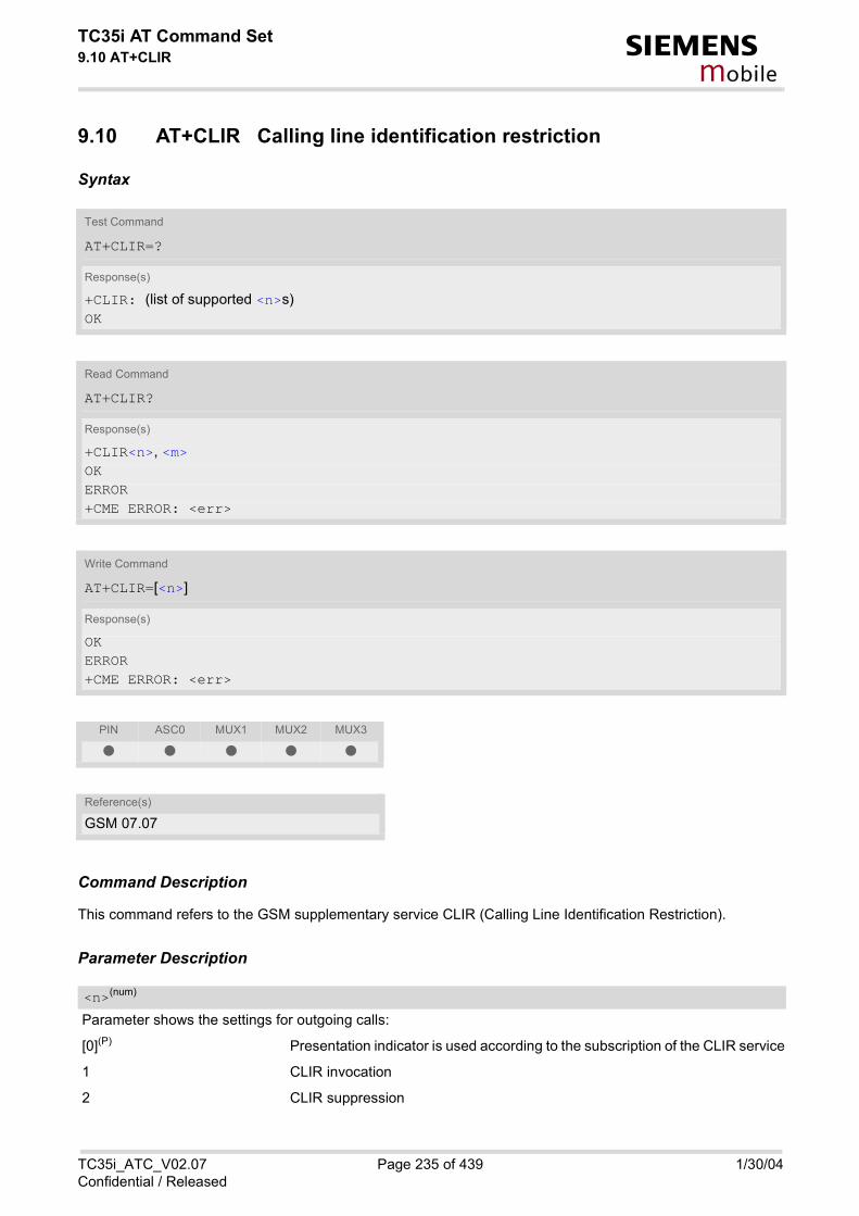
TC35i AT Command Set9.10 AT+CLIR s
mobile
9.10 AT+CLIR Calling line identification restriction
Syntax
Command Description
This command refers to the GSM supplementary service CLIR (Calling Line Identification Restriction).
Parameter Description
Parameter shows the settings for outgoing calls:
[0](P) Presentation indicator is used according to the subscription of the CLIR service
1 CLIR invocation
2 CLIR suppression
Test Command
AT+CLIR=?
Response(s)
+CLIR: (list of supported <n>s) OK
Read Command
AT+CLIR?
Response(s)
+CLIR<n>, <m> OKERROR+CME ERROR: <err>
Write Command
AT+CLIR=[<n>]
Response(s)
OKERROR+CME ERROR: <err>
PIN ASC0 MUX1 MUX2 MUX3
� � � � �
Reference(s)
GSM 07.07
<n>(num)
TC35i_ATC_V02.07 Page 235 of 439 1/30/04Confidential / Released

TC35i AT Command Set9.10 AT+CLIR s
mobile
Parameter shows the subscriber CLIR service status in the network:
0 CLIR not provisioned
1 CLIR provisioned in permanent mode
2 Unknown (e.g. no network, etc.)
3 CLIR temporary mode presentation restricted
4 CLIR temporary mode presentation allowed
Note
• The settings made with AT+CLIR=1 or AT+CLIR=2 are used for all outgoing calls until the ME is switched offor AT+CLIR=0 is used.
<m>(num)
TC35i_ATC_V02.07 Page 236 of 439 1/30/04Confidential / Released

TC35i AT Command Set9.11 AT+CPUC s
mobile
9.11 AT+CPUC Price per unit and currency table
Syntax
Command Description
Read command returns the current parameters of PUC.
Write command sets the parameters of Advice of Charge related price per unit and currency table. SIM PIN2 isusually required to set the parameters.
Parameter Description
Three-character currency code (e.g. "GBP", "EUR"). If the currency name is longer than three characters, allcharacters will be cut off after the third position. Before they are written to the SIM Card, these characters areconverted to the standard GSM alphabet.
Test Command
AT+CPUC=?
Response(s)
OK
Read Command
AT+CPUC?
Response(s)
+CPUC: <currency>, <ppu> OKERROR+CME ERROR: <err>
Write Command
AT+CPUC=<currency>, <ppu>[, <passwd>]
Response(s)
OKERROR+CME ERROR: <err>
PIN ASC0 MUX1 MUX2 MUX3
� � � � �
Reference(s)
GSM 07.07
<currency>(str)(+CSCS)
TC35i_ATC_V02.07 Page 237 of 439 1/30/04Confidential / Released

TC35i AT Command Set9.11 AT+CPUC s
mobile
Price per unit; dot is used as a decimal separator (e.g. "2.66"). The length is limited to 20 characters. If the stringlength is exceeded, the command is terminated with an error. This string may only contain digits and a dot. Lead-ing zeros are removed from the string. The minimum and maximum value are determined by the structure of theSIM-PUCT file. The maximum price per unit value is 999 999 999.00. When successfully entered, this value isrounded to maximum accuracy.Note: Due to storage in mantisse (range 0-4095) and exponent (-7 to 7) it is possible that rounding errors occur.
SIM PIN2. String parameter which can contain any combination of characters. The maximum string length islimited to 8 characters. If this value is exceeded, the command terminates with an error message. If the PIN2 isincorrect, a CME error (+CME ERROR: incorrect password) is output.
Example
To change currency and/or price per unit you have two ways:
You can enter PIN2 along with the AT+CPUC command:
Alternatively, you can first use the AT+CPIN2 command to enter PIN2. When you execute the AT+CPUC com-mand, subsequently, take into account that PIN2 authentication expires after 300ms (see notes in AT+CPIN2).
<ppu>(str)
<passwd>(str)
AT+CPUC="EUR","0.10","8888" (where "8888" = PIN2)OK
AT+CPUC="EUR","0.10"
OK SuccessfulAT+CPUC="EUR","0.10"
+CME ERROR: SIM PIN2 required Attempt not successful. PIN2 authentication has expired.
TC35i_ATC_V02.07 Page 238 of 439 1/30/04Confidential / Released

TC35i AT Command Set9.12 AT+CSSN s
mobile
9.12 AT+CSSN Supplementary service notifications
Syntax
Unsolicited Result Codes
URC 1
+CSSI: <code 1>
When <n>=1 and a supplementary service notification is received after a mobile originated call setup, inter-mediate result code "+CSSI": <code 1> is sent to TE before any other MO call setup result codes
URC 2
+CSSU: <code 2>
When <m>=1 and a supplementary service notification is received during a mobile terminated call setup orduring a call, unsolicited result code "+CSSU": <code 2> is sent to TE.
Test Command
AT+CSSN=?
Response(s)
+CSSN: (list of supported<n>s), (list of supported<m>s) OK
Read Command
AT+CSSN?
Response(s)
+CSSN: <n>, <m> OK
Write Command
AT+CSSN=<n>[, <m>]
Response(s)
OKERROR+CME ERROR
PIN ASC0 MUX1 MUX2 MUX3
� � � � �
Reference(s)
GSM 07.07
TC35i_ATC_V02.07 Page 239 of 439 1/30/04Confidential / Released

TC35i AT Command Set9.12 AT+CSSN s
mobile
Command Description
The write command enables or disables the presentation of URCs for supplementary services.
Parameter Description
0(&F) Suppress "+CSSI" URCs
1 Activate "+CSSI" URCs
0(&F) Suppress "+CSSU" URCs
1 Activate "+CSSU" URCs
3 Waiting call is pending
0 The incoming call is a forwarded call.
5 Held call was terminated
Note
• The URCs will be displayed only if the call concerned is a voice call.
<n>(num)
<m>(num)
<code 1>(num)
<code 2>(num)
TC35i_ATC_V02.07 Page 240 of 439 1/30/04Confidential / Released

TC35i AT Command Set9.13 AT+CUSD s
mobile
9.13 AT+CUSD Supplementary service notifications
This command allows control of the Unstructured Supplementary Service Data (USSD) according to GSM 02.90.Both network and mobile initiated operations are supported.
Syntax
Unsolicited Result Code
+CUSD: <m>[<str>[<dcs>]]
URC "+CUSD" indicates an USSD response from the network, or network initiated operation
Command Description
The read command returns the current <n> value
Write command parameter <n> is used to disable/enable the presentation of an unsolicited result code (USSDresponse from the network, or network initiated operation) "+CUSD: <m>[<str>[<dcs>]]" to the TE.When <str> is given, a mobile initiated USSD string or a response USSD string to a network initiated operation
Test Command
AT+CUSD=?
Response(s)
+CUSD: (list of supported<n>s) OK
Read Command
AT+CUSD?
Response(s)
+CUSD: <n> OK
Write Command
AT+CUSD=<n>[, <str>[, <dcs>]]
Response(s)
OK+CME ERROR
PIN ASC0 MUX1 MUX2 MUX3
� � � � �
Reference(s)
GSM 07.07, GSM 02.90, GSM 03.90, GSM 04.90
TC35i_ATC_V02.07 Page 241 of 439 1/30/04Confidential / Released

TC35i AT Command Set9.13 AT+CUSD s
mobile
is sent to the network. The response USSD string from the network is returned in a subsequent unsolicited resultcode "+CUSD" The interaction of this command with other commands based on other GSM supplementary services is describedin the GSM standard.
Parameter Description
0(&F) Disable the result code presentation in the TA
1 Enable the result code presentation in the TA
2 Cancel session (not applicable to read command response)
String type USSD-string (when <str> parameter is not given, network is not interrogated). If <dcs> indicates that GSM 03.38 default alphabet is used TA converts GSM alphabet into current TE characterset according to rules of GSM 07.05 Annex A.
GSM 03.38 Cell Broadcast Data Coding Scheme in integer format (default 15)
0 No further user action required (network initiated USSD-Notify, or no furtherinformation needed after mobile initiated operation)
1 Further user action required (network initiated USSD-Request, or further infor-mation needed after mobile initiated operation). If <m>=1, then the URC ends with ">" to prompt the user for input. The useraction is finished with <CTRL-Z> or aborted with <ESC>.
2 USSD terminated by network.
Notes
• For the write command, only <dcs>= 15 is supported.
• When a USSD string is sent via ATD, a "AT+CUSD=1" is executed implicitly.
<n>(num)
<str>(str)
<dcs>(num)
<m>(num)
TC35i_ATC_V02.07 Page 242 of 439 1/30/04Confidential / Released

TC35i AT Command Set10. FAX Commands s
mobile
10. FAX Commands
The following commands can be used for FAX transmission. If the ME is acting as a Fax-Modem to a PC-based application (e.g. "WinFax") it is necessary to select the proper Service Class (Fax Class) provided by the ME. The ME reports its Service Class capabilities, both the current setting and the range of services avaible. This is provided by the AT+FCLASS command. Service Classes supported by ME:
The following AT commands are dummy commands: AT+FAA Auto Answer modeAT+FECM Error Correction Mode controlAT+FLNFC Page Length format conversionAT+FLPL Indicate document available for pollingAT+FMINSP Minimum Phase C speedAT+FRBC Phase C data receive byte countAT+FREL Phase C received EOL alignmentAT+FSPL Enable pollingAT+FTBC Phase C data transmit byte countAT+FWDFC Page width format conversionInvoking these commands will not cause ERROR result codes, but these commands have no functionality.
10.1 FAX parameters
Parameter Description
Binary File Transfer ModeNote: Only the default value needs to be implemented. Use test command to check which parameter values arereally possible!
[0] disable BFT
1 enable BFT
Bit Rate
0 2400 bit/s, V.27ter
1 4800 bit/s, V.27ter
2 7200 bit/s, V.29
[3] 9600 bit/s, V.29
AT+FCLASS Parameter Service class Reference, Standard
0 data modem e.g. TIA/EIA-602 or ITU V.25ter
1 Service Class 1 EIA/TIA-578-A
2 manufacture specific this document and EIA PN-2388 (draft)
<bf>(num)
<br>(num)
TC35i_ATC_V02.07 Page 243 of 439 1/30/04Confidential / Released

TC35i AT Command Set10.1 FAX parameters s
mobile
Data Compression FormatNote: Only the default value needs to be implemented. Use test command to check which parameter values arereally possible!
[0] 1-D modified Huffman
1 2-D modified read
2 2-D uncompressed mode
Error Correction ModeNote: Only the default value needs to be implemented. Use test command to check which parameter values arereally possible!
[0] disable ECM
1 enable ECM, 64 bytes/frame
2 enable ECM, 256 bytes/frame
Page Length
0 A4, 297mm
1 B4, 364mm
[2] unlimited length
modulation mode
3 V21 Ch2 - 300 bps
24 V.27ter - 2400 bps
27 V.27ter - 4800 bps
48 V.27ter - 7200 bps
72 V.29 - 7200 bps
96 V.29 - 9600 bps
Scan Time/LineNote: Only the default value needs to be implemented. Use test command to check which parameter values arereally possible!
[0] 0 ms (at VR= normal)
1 5 ms
2 10 ms
3 10 ms
4 20 ms
5 20 ms
<df>(num)
<ec>(num)
<ln>(num)
<mod>(num)
<st>(num)
TC35i_ATC_V02.07 Page 244 of 439 1/30/04Confidential / Released

TC35i AT Command Set10.1 FAX parameters s
mobile
6 40 ms
7 40 ms
Vertical Resolution
0 normal, 98 lpi
[1] fine, 196 lpi
Page Width
[0] 1728 pixels in 215mm
1 2048 pixels in 255 mm
2 2432 pixels in 303 mm
3 1216 pixels in 151 mm
4 864 pixels in 107 mm
Note
• Only the default value needs to be implemented. Use test command to check which parameter values arereally possible
<vr>(num)
<wd>(num)
TC35i_ATC_V02.07 Page 245 of 439 1/30/04Confidential / Released

TC35i AT Command Set10.2 AT+FBADLIN s
mobile
10.2 AT+FBADLIN Bad Line Treshold
Syntax
Command Description
This command defines the Copy-Quality-OK-threshold. If <badlin> consecutive lines have pixel count errorsin normal resolution (98 dpi) mode, then the copy quality is unacceptable. If <badlin> * 2 consecutive lines havepixel count errors in fine resolution (196 dpi) mode, then the copy quality is unacceptable. "Copy Quality Not OK"occurs if either the error percentage is too high or too many consecutive lines contain errors. A value of 0 impliesthat error checking is not present or disabled.
Parameter Description
bad lines
0...10(P)...255
Note
• Used for Fax Class 2 only
Read Command
AT+FBADLIN?
Response(s)
<badlin> OK
Write Command
AT+FBADLIN=<badlin>
Response(s)
OKIf error is related to ME functionalityERROR
PIN ASC0 MUX1 MUX2 MUX3
� � � � �
Reference(s)
EIA PN-2388
<badlin>(num)
TC35i_ATC_V02.07 Page 246 of 439 1/30/04Confidential / Released

TC35i AT Command Set10.3 AT+FBADMUL s
mobile
10.3 AT+FBADMUL Error Threshold Multiplier
Syntax
Command Description
This command defines the "Copy-Quality-OK" multiplier. The number of lines received with a bad pixel count ismultiplied by this number. If the result exceeds the total number of lines on the page the error rate is consideredtoo high. A threshold multiplier value of 20 corresponds to a 5 per cent error rate. A value of 0 implies that errorchecking is not present or disabled.
Parameter Description
0...20(P)...255
Note
• Used for Fax Class 2 only
Read Command
AT+FBADMUL?
Response(s)
<badmul> OK
Write Command
AT+FBADMUL=<badmul>
Response(s)
OKIf error is related to ME functionality:ERROR
PIN ASC0 MUX1 MUX2 MUX3
� � � � �
Reference(s)
EIA PN-2388
<badmul>(num)
TC35i_ATC_V02.07 Page 247 of 439 1/30/04Confidential / Released

TC35i AT Command Set10.4 AT+FBOR s
mobile
10.4 AT+FBOR Query data bit order
Syntax
Command Description
Query the bit order for receive-mode. The mode is set by the ME depending on the selected Service Class, see"AT+FCLASS Fax: Select, read or test service class".
Parameter Description
bit order modes
0 Direct bit order for both Phase C and for Phase B/D data.
[1] Reversed bit order for Phase C data, direct Bit Order for Phase B/D data.
Note
• Used for Fax Class 2 only
Test Command
AT+FBOR=?
Response(s)
(list of supported <bor>s) OK
Read Command
AT+FBOR?
Response(s)
<bor> OK
Write Command
AT+FBOR=<bor>
Response(s)
OK
PIN ASC0 MUX1 MUX2 MUX3
� � � � �
Reference(s)
EIA PN-2388
<bor>(num)
TC35i_ATC_V02.07 Page 248 of 439 1/30/04Confidential / Released

TC35i AT Command Set10.5 AT+FCIG s
mobile
10.5 AT+FCIG Query or set the Local polling id
Syntax
Parameter Description
Local Polling ID string, max. length and possible content as reported by test command. Default value is emptystring ("").
Notes
• Used for Fax Class 2 only
• See also AT+FLID Query or set the Local Id setting capabilities.
Test Command
AT+FCIG=?
Response(s)
(max. length of Local Polling ID string) (range of supported ASCII character values) OK
Read Command
AT+FCIG?
Response(s)
<id> OK
Write Command
AT+FCIG=<id>
Response(s)
OK
PIN ASC0 MUX1 MUX2 MUX3
� � � � �
Reference(s)
EIA PN-2388
<id>(num)
TC35i_ATC_V02.07 Page 249 of 439 1/30/04Confidential / Released

TC35i AT Command Set10.6 AT+FCLASS s
mobile
10.6 AT+FCLASS Fax: Select, read or test service class
Syntax
Command Description
The ME is set to a particular mode of operation (data, fax). This causes the MA to process information in a man-ner suitable for that type of information.
Parameter Description
[0](&F) data (e.g. EIA/TIA-602 or ITU V.25ter)
1 Fax class 1 (EIA/TIA-578-A, Service Class 1)
2 Fax class 2 (EIA/TIA SP-2388, an early draft version of EIA/TIA-592-A - Ser-vice class 2.1)
Notes
• Using Error Correcting Mode (ECM) when sending FAXes over GSM should be avoided
Test Command
AT+FCLASS=?
Response(s)
(list of supported <n>s) OK
Read Command
AT+FCLASS?
Response(s)
<n> OK
Write Command
AT+FCLASS=<n>
Response(s)
OK
PIN ASC0 MUX1 MUX2 MUX3
� � � � �
Reference(s)
EIA/TIA-592-A
<n>(num)(&W)(&V)
TC35i_ATC_V02.07 Page 250 of 439 1/30/04Confidential / Released

TC35i AT Command Set10.6 AT+FCLASS s
mobile
• If <n> is set to 1 or 2, all incoming calls will be answered as fax calls with ATA, if ATA is issued on multiplexerchannel 1 resp. ASC0. For calls explicitly signalled as voice or data calls, this procedure will fail with resultcode "NO CARRIER", but the call in question will continue to ring.It is possible to change the setting of <n> to 0 while the call is ringing, and accept the call normally afterwardswith ATA. In automatic answer mode (setting of ATS0 is different from 0) a voice call will be established automaticallyindependent of the setting of <n>.
TC35i_ATC_V02.07 Page 251 of 439 1/30/04Confidential / Released

TC35i AT Command Set10.7 AT+FCQ s
mobile
10.7 AT+FCQ Copy Quality Checking
Syntax
Command Description
This command controls Copy Quality checking when receiving a fax.
Parameter Description
0 No copy quality checking. The ME will generate Copy Quality OK (MCF)responses to complete pages.
[1] ME can check 1-D phase data. The connected application must check copyquality for 2-D phase C data.
Note
• Used for Fax Class 2 only
Test Command
AT+FCQ=?
Response(s)
(list of supported copy quality checking <cq>s) OK
Read Command
AT+FCQ?
Response(s)
<cq> OK
Write Command
AT+FCQ=<cq>
Response(s)
OK
PIN ASC0 MUX1 MUX2 MUX3
� � � � �
Reference(s)
EIA PN-2388
<cq>(num)
TC35i_ATC_V02.07 Page 252 of 439 1/30/04Confidential / Released

TC35i AT Command Set10.8 AT+FCR s
mobile
10.8 AT+FCR Capability to receive
Syntax
Parameter Description
[0] ME will not receive message data. This can be used when the application hasinsufficient storage. The ME can send and can be polled for a file.
1 ME can receive message data.
Note
• Used for Fax Class 2 only
Write Command
AT+FCR=<cr>
Response(s)
OK
PIN ASC0 MUX1 MUX2 MUX3
� � � � �
Reference(s)
EIA PN-2388
<cr>(num)
TC35i_ATC_V02.07 Page 253 of 439 1/30/04Confidential / Released

TC35i AT Command Set10.9 AT+FDCC s
mobile
10.9 AT+FDCC Query or set capabilities
Syntax
Command Description
This command allows the connected application to sense and constrain the capabilities of the facsimile DCE(=ME), from the choices defined in CCITT T.30 Table 2.
Notes
• For further information see AT+FDIS.
• Used for Fax Class 2 only
Test Command
AT+FDCC=?
Response(s)
(list of <vr>s), (list of <br>s), (list of <wd>s), (list of <ln>s), (list of <df>s), (list of <ec>s), (list of <bf>s), (list of <st>s) OK
Read Command
AT+FDCC?
Response(s)
<vr>, <br>, <wd>, <ln>, <df>, <ec>, <bf>, <st> OK
Write Command
AT+FDCC=<vr>, <br>, <wd>, <ln>, <df>, <ec>, <bf>, <st>
Response(s)
OK
PIN ASC0 MUX1 MUX2 MUX3
� � � � �
Reference(s)
EIA PN-2388
TC35i_ATC_V02.07 Page 254 of 439 1/30/04Confidential / Released

TC35i AT Command Set10.10 AT+FDFFC s
mobile
10.10 AT+FDFFC Data Compression Format Conversion
Syntax
Command Description
This parameter determines the ME response to a mismatch between the data format negotiated for the fax ses-sion, reported by the <df> subparameter, and the Phase C data desired by the controlling application, indicatedby the optional AT+FDT <df> subparameter, or the AT+FDIS <df> subparameter for AT+FDR operation.
Parameter Description
[0] Mismatch checking is always disabled. The controlling application has to checkthe <df> subparameter and transfer matching data.
Notes
• For further information see AT+FDIS.
• Used for Fax Class 2 only.
Test Command
AT+FDFFC=?
Response(s)
(list of <df>s) OK
Read Command
AT+FDFFC?
Response(s)
<df> OK
Write Command
AT+FDFFC=<df>
Response(s)
OK
PIN ASC0 MUX1 MUX2 MUX3
� � � � �
Reference(s)
EIA PN-2388
<df>(num)
TC35i_ATC_V02.07 Page 255 of 439 1/30/04Confidential / Released

TC35i AT Command Set10.11 AT+FDIS s
mobile
10.11 AT+FDIS Query or set session parameters
Syntax
Command Description
This command allows the controlling application to sense and constrain the capabilities used for the current ses-sion. It uses AT+FDIS to generate DIS or DTC messages directly, and uses AT+FDIS and received DIS mes-sages to generate DCS messages.
Note
• Used for Fax Class 2 only
Test Command
AT+FDIS=?
Response(s)
(list of <vr>s), (list of <br>s), (list of <wd>s), (list of <ln>s), (list of <df>s), (list of <ec>s), (list of <bf>s), (list of <st>s) OK
Read Command
AT+FDIS?
Response(s)
<vr>, <br>, <wd>, <ln>, <df>, <ec>, <bf>, <st> OK
Write Command
AT+FDIS=<vr>, <br>, <wd>, <ln>, <df>, <ec>, <bf>, <st>
Response(s)
OK
PIN ASC0 MUX1 MUX2 MUX3
� � � � �
Reference(s)
EIA PN-2388
TC35i_ATC_V02.07 Page 256 of 439 1/30/04Confidential / Released

TC35i AT Command Set10.12 AT+FDR s
mobile
10.12 AT+FDR Begin or continue phase C data reception
Syntax
Command Description
The command initiates transition to Phase C data reception.
Note
• Used for Fax Class 2 only
Exec Command
AT+FDR
Response(s)
CONNECTorOKIf error related to ME functionalityERROR
PIN ASC0 MUX1 MUX2 MUX3
� � � � �
Reference(s)
EIA PN-2388
TC35i_ATC_V02.07 Page 257 of 439 1/30/04Confidential / Released

TC35i AT Command Set10.13 AT+FDT s
mobile
10.13 AT+FDT Data Transmission
Syntax
Command Description
This command requests the ME to transmit a Phase C page. When the ME is ready to accept Phase C data, itissues the negotiation responses and the CONNECT result code to the application. In Phase B, the AT+FDT command releases the ME to proceed with negotiation, and releases the DCS messageto the remote station. In Phase C, the AT+FDT command resumes transmission after the end of a data streamtransmited before.
Note
• Used for Fax Class 2 only
Exec Command
AT+FDT
Response(s)
CONNECT
Write Command
AT+FDT=<df>, <vr>, <wd>, <ln>
Response(s)
CONNECT
PIN ASC0 MUX1 MUX2 MUX3
� � � � �
Reference(s)
EIA PN-2388
TC35i_ATC_V02.07 Page 258 of 439 1/30/04Confidential / Released

TC35i AT Command Set10.14 AT+FET s
mobile
10.14 AT+FET End a page or document
Syntax
Command Description
This command indicates that the current page or partial page is complete. An ERROR response code results ifthis command is issued while the mode is on-hook.
Parameter Description
Post Page Message Codes
1 another document next
2 no more pages or documents
4 another page, procedure interrupt
5 another document, procedure interrupt
Note
• Used for Fax Class 2 only
Write Command
AT+FET=<ppm>
Response(s)
OK
PIN ASC0 MUX1 MUX2 MUX3
� � � � �
Reference(s)
EIA PN-2388
<ppm>(num)
TC35i_ATC_V02.07 Page 259 of 439 1/30/04Confidential / Released

TC35i AT Command Set10.15 AT+FK s
mobile
10.15 AT+FK Kill operation, orderly FAX abort
Syntax
Command Description
This command causes the TA to terminate the session in an orderly manner.
Note
• Used for Fax Class 2 only
Exec Command
AT+FK
Response(s)
OK
PIN ASC0 MUX1 MUX2 MUX3
� � � � �
TC35i_ATC_V02.07 Page 260 of 439 1/30/04Confidential / Released

TC35i AT Command Set10.16 AT+FLID s
mobile
10.16 AT+FLID Query or set the Local Id setting capabilities
Syntax
Parameter Description
Local ID stringmax. length and possible content as reported by test command. Default value is empty string ("").
Notes
• Used for Fax Class 2 only
• See also AT+FCIG Query or set the Local polling id
Test Command
AT+FLID=?
Response(s)
(max. character length of Local ID string) (range of supported ASCII character values) OK
Read Command
AT+FLID?
Response(s)
<lid> OK
Write Command
AT+FLID=<lid>
Response(s)
OK
PIN ASC0 MUX1 MUX2 MUX3
� � � � �
Reference(s)
EIA PN-2388
<lid>(num)
TC35i_ATC_V02.07 Page 261 of 439 1/30/04Confidential / Released

TC35i AT Command Set10.17 AT+FMDL s
mobile
10.17 AT+FMDL identify Product Model
Syntax
Command Description
Send the model identification to the TA.
Note
• Used for Fax Class 2 only
Read Command
AT+FMDL?
Response(s)
Gipsy Soft ProtocolstackOK
PIN ASC0 MUX1 MUX2 MUX3
� � � � �
Reference(s)
SIEMENS
TC35i_ATC_V02.07 Page 262 of 439 1/30/04Confidential / Released

TC35i AT Command Set10.18 AT+FMFR s
mobile
10.18 AT+FMFR Request Manufacturer Identification
Syntax
Command Description
Send the manufacturer identification to the TA.
Note
• Used for Fax Class 2 only
Read Command
AT+FMFR?
Response(s)
SIEMENSOK
PIN ASC0 MUX1 MUX2 MUX3
� � � � �
Reference(s)
SIEMENS
TC35i_ATC_V02.07 Page 263 of 439 1/30/04Confidential / Released

TC35i AT Command Set10.19 AT+FOPT s
mobile
10.19 AT+FOPT Set bit order independently
Syntax
Command Description
Model specific command to set bit order independently of the understanding which is "mirrored" and which isdirect.
Parameter Description
0 non-standard
1 standard
Note
• Used for Fax Class 2 only
Write Command
AT+FOPT=<opt>
Response(s)
OK
PIN ASC0 MUX1 MUX2 MUX3
� � � � �
Reference(s)
SIEMENS
<opt>(num)
TC35i_ATC_V02.07 Page 264 of 439 1/30/04Confidential / Released

TC35i AT Command Set10.20 AT+FPHCTO s
mobile
10.20 AT+FPHCTO DTE Phase C Response Timeout
Syntax
Command Description
The time-out value <tout> determines how long the DCE will wait for a command after reaching the end of datawhen transmitting in Phase C. When time-out is reached, the DCE assumes that there are no more pages ordocuments to send.
Parameter Description
TimeoutValue in 100ms units
0...30(P)...255
Note
• Used for Fax Class 2 only
Read Command
AT+FPHCTO?
Response(s)
<tout> OK
Write Command
AT+FPHCTO=<tout>
Response(s)
OKIf error is related to ME functionalityERROR
PIN ASC0 MUX1 MUX2 MUX3
� � � � �
Reference(s)
EIA PN-2388
<tout>(num)
TC35i_ATC_V02.07 Page 265 of 439 1/30/04Confidential / Released

TC35i AT Command Set10.21 AT+FREV s
mobile
10.21 AT+FREV Identify Product Revision
Syntax
Command Description
Sends the revision identification to the TA.
Note
• Used for Fax Class 2 only
Read Command
AT+FREV?
Response(s)
V2.550OK
PIN ASC0 MUX1 MUX2 MUX3
� � � � �
Reference(s)
SIEMENS
TC35i_ATC_V02.07 Page 266 of 439 1/30/04Confidential / Released

TC35i AT Command Set10.22 AT+FRH s
mobile
10.22 AT+FRH Receive Data Using HDLC Framing
Syntax
Command Description
This command causes the TA to receive frames using the HDLC protocol and the modulation defined below. AnERROR response code results if this command is issued while the modem is on-hook.
Note
• Used for Fax Class 1 only
Write Command
AT+FRH=<mod>
Response(s)
CONNECTIf error related to ME functionalityERROR
PIN ASC0 MUX1 MUX2 MUX3
� � � � �
Reference(s)
TIA/EIA-578
TC35i_ATC_V02.07 Page 267 of 439 1/30/04Confidential / Released

TC35i AT Command Set10.23 AT+FRM s
mobile
10.23 AT+FRM Receive Data
Syntax
Command Description
This command causes the TA to enter the receiver-mode using the modulation defined below. An ERRORresponse code results if this command is issued while the modem is on-hook.
Notes
• Used for Fax Class 1 only
• <mod>= 3 is not possible
Test Command
AT+FRM=?
Response(s)
(list of <mod>s) OK
Write Command
AT+FRM=<mod>
Response(s)
CONNECTIf error is related to ME functionality:ERROR
PIN ASC0 MUX1 MUX2 MUX3
� � � � �
Reference(s)
TIA/EIA-578
TC35i_ATC_V02.07 Page 268 of 439 1/30/04Confidential / Released

TC35i AT Command Set10.24 AT+FRS s
mobile
10.24 AT+FRS Receive Silence
Syntax
Command Description
<time>=n causes the TA to report an OK result code to the TE after <time> 10 millisecond intervals of silencehave been detected on the line. This command is aborted if any character is received by the DTE. The modemdiscards the aborting character and issues an OK result code. An ERROR response code results if this commandis issued while the mode is on-hook
Parameter Description
no. of 10 millisecond intervals
0...255
Note
• Used for Fax Class 1 only
Write Command
AT+FRS=<time>
Response(s)
OKIf error related to ME functionalityERROR
PIN ASC0 MUX1 MUX2 MUX3
� � � � �
Reference(s)
TIA/EIA-578
<time>(num)
TC35i_ATC_V02.07 Page 269 of 439 1/30/04Confidential / Released
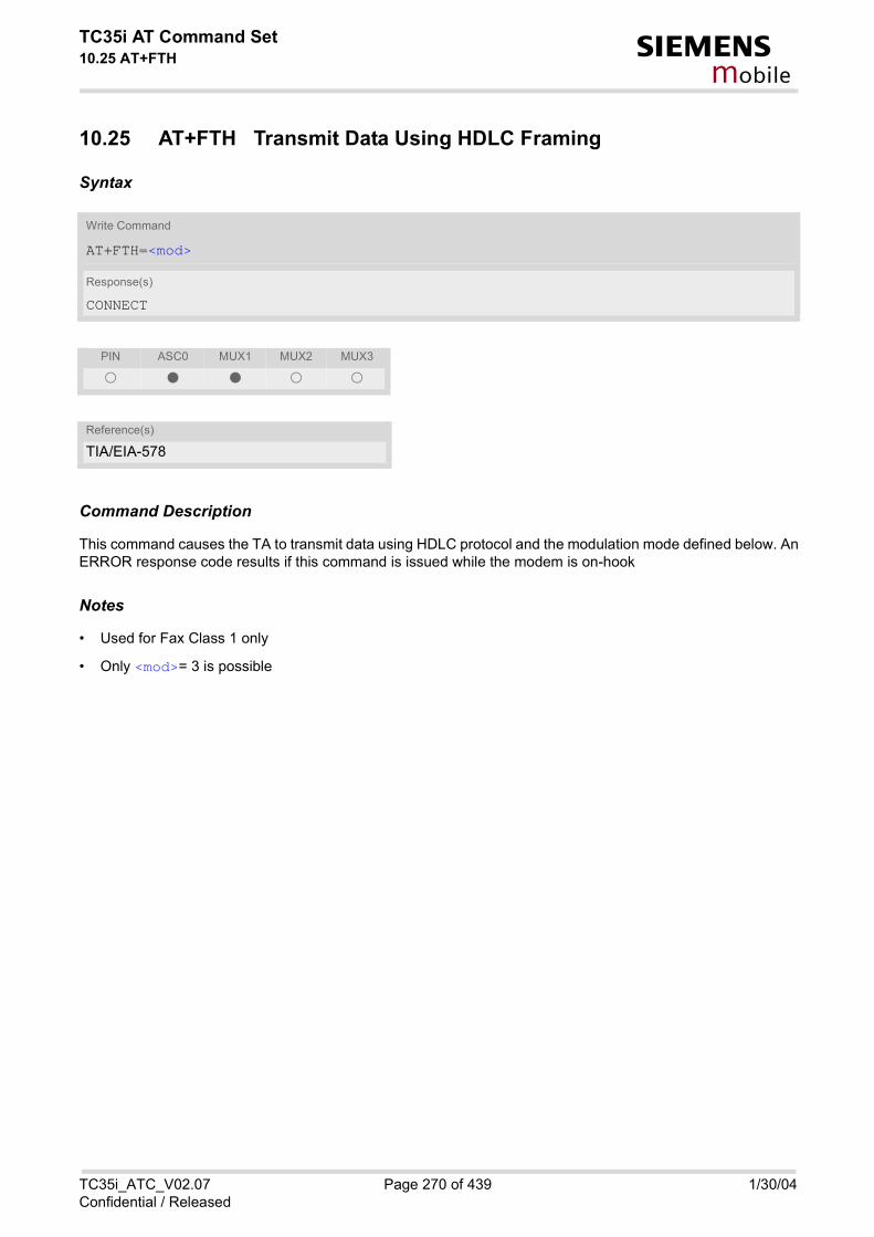
TC35i AT Command Set10.25 AT+FTH s
mobile
10.25 AT+FTH Transmit Data Using HDLC Framing
Syntax
Command Description
This command causes the TA to transmit data using HDLC protocol and the modulation mode defined below. AnERROR response code results if this command is issued while the modem is on-hook
Notes
• Used for Fax Class 1 only
• Only <mod>= 3 is possible
Write Command
AT+FTH=<mod>
Response(s)
CONNECT
PIN ASC0 MUX1 MUX2 MUX3
� � � � �
Reference(s)
TIA/EIA-578
TC35i_ATC_V02.07 Page 270 of 439 1/30/04Confidential / Released

TC35i AT Command Set10.26 AT+FTM s
mobile
10.26 AT+FTM Transmit Data
Syntax
Command Description
This command causes the TA to transmit data using the modulation mode defined below. An ERROR responsecode results if this command is issued while the modem is on-hook.
Notes
• Used for Fax Class 1 only
• <mod>= 3 is not possible
Test Command
AT+FTM=?
Response(s)
(list of <mod>s) OK
Write Command
AT+FTM=<mod>
Response(s)
CONNECTIf error is related to ME functionalityERROR
PIN ASC0 MUX1 MUX2 MUX3
� � � � �
Reference(s)
TIA/EIA-578
TC35i_ATC_V02.07 Page 271 of 439 1/30/04Confidential / Released

TC35i AT Command Set10.27 AT+FTS s
mobile
10.27 AT+FTS Stop Transmission and Wait
Syntax
Command Description
This command causes the TA to terminate a transmission and wait for <time> 10 millisecond intervals beforeresponding with the OK result code to the DTE.
Parameter Description
no. of 10 millisecond intervals
0...85
Note
• Used for Fax Class 1 only
Write Command
AT+FTS=<time>
Response(s)
An ERROR response code results if this command is issued while the modem is on-hook.
PIN ASC0 MUX1 MUX2 MUX3
� � � � �
Reference(s)
TIA/EIA-578
<time>(num)
TC35i_ATC_V02.07 Page 272 of 439 1/30/04Confidential / Released

TC35i AT Command Set10.28 AT+FVRFC s
mobile
10.28 AT+FVRFC Vertical resolution format conversion
Syntax
Command Description
This command determines the DCE response to a mismatch between the vertical resolution negotiated for thefacsimile session and the Phase C data desired by the DTE.
Parameter Description
0 Disable mismatch checking.
[2] Enable mismatch checking, with resolution conversion of 1-D data in the DCE,and an implied AT+FK command executed on 2-D mismatch detection.
Note
• Used for Fax Class 2 only
Test Command
AT+FVRFC=?
Response(s)
(list of supported <vrfc>s) OK
Read Command
AT+FVRFC?
Response(s)
<vrfc> OK
Write Command
AT+FVRFC=<vrfc>
Response(s)
OK
PIN ASC0 MUX1 MUX2 MUX3
� � � � �
Reference(s)
EIA PN-2388
<vrfc>(num)
TC35i_ATC_V02.07 Page 273 of 439 1/30/04Confidential / Released

TC35i AT Command Set11. Short Message Service (SMS) Commands s
mobile
11. Short Message Service (SMS) Commands
The AT Commands described in this chapter allow an external application to use the Short Message Service with the TC35i.
11.1 SMS parameters
Parameter Description
Format is same for <pdu> in case of SMS, but without GSM 24.11 SC address field and parameter shall bebounded by double quote characters like a normal string type rarameter
String type alphanumeric representation of <da> or <oa> corresponding to the entry found in phonebook; imple-mentation of this feature is manufacturer specific
Command DataGSM 03.40 TP-Command-Data in text mode responses; ME/TA converts each 8-bit octet into two IRA characterlong hexadecimal numbers (e.g. octet with integer value 42 is presented to TE as two characters 2A (IRA 50and 65))
Command TypeGSM 03.40 TP-Command-Type in integer format
[0]...255
Destination AddressGSM 03.40 TP- Destination-Address Address-Value field in string format; BCD numbers (or GSM default alpha-bet characters) are converted into characters; type of address given by <toda>
User DataIn case of SMS: GSM 03.40 TP-User-Data in text mode responses; format:• If <dcs> indicates that GSM 03.38 default alphabet is used and <fo> indicates that GSM 03.40 TP-User-
Data-Header-Indication is not set: ME/TA converts GSM alphabet into current TE character set according torules covered in Annex A.
• If <dcs> indicates that 8-bit or UCS2 data coding scheme is used, or <fo> indicates that GSM 03.40 TP-User-Data-Header-Indication is set: ME/TA converts each 8-bit octet into hexadecimal numbers con-tainingtwo IRA characters (e.g. octet with integer value 42 is presented to TE as two characters 2A (IRA 50 and 65).
In case of CBS: GSM 03.41 CBM Content of Message in text mode responses; format:• If <dcs> indicates that GSM 03.38 default alphabet is used: ME/TA converts GSM alphabet into current TE
character set according to rules covered in Annex A.
<ackpdu>(num)
<alpha>(str)(+CSCS)
<cdata>(num)
<ct>(num)
<da>(num)(+CSCS)
<data>(num)(+CSCS)
TC35i_ATC_V02.07 Page 274 of 439 1/30/04Confidential / Released

TC35i AT Command Set11.1 SMS parameters s
mobile
• If <dcs> indicates that 8-bit or UCS2 data coding scheme is used: ME/TA converts each 8-bit octet into hexa-decimal numbers containing two IRA characters.
Discharge TimeGSM 03.40 TP-Discharge-Time in time-string format: "yy/MM/dd,hh:mm:ss+zz", where characters indicate year(two last digits), month, day, hour, minutes, seconds and time zone. For example, 6th of May 1994, 22:10:00GMT+2 hours equals "94/05/06,22:10:00+08"
IEIa (Information Element Identifier octet) of the concatenated SMS.
8 Concatenated short messages, 8-bit reference number
16 Concatenated short messages, 16-bit reference number
Integer type; value in the range of location numbers supported by the associated memory
Message LengthInteger type value indicating in the text mode (AT+CMGF=1) the length of the message body <data> (or<cdata>) in characters; or in PDU mode (AT+CMGF=0), the length of the actual TP data unit in octets (i.e. theRP layer SMSC address octets are not counted in the length) In text mode, the maximum length of an SMSdepends on the used coding scheme: It is 160 characters if the 7 bit GSM coding scheme is used, and 140 char-acters according to the 8 bit GSM coding scheme. If the SMS message format is ''text mode'' (AT+CMGF=1) and the character set is set to ''UCS2'' with AT+CSCSand the SMS is also coded as "UCS2" (see <dcs> of AT+CSMP), then the length is in octets instead of charac-ters. For concatenated SMS messages the maximum length will be reduced by the length of the user data headerwith respect to <ieia> (6 bytes for <ieia>=8 and 7 bytes for <ieia>=16). In the case of 8-bit data, the max-imum length of the short message field is: 140 octets - (6 or 7) = 134 or 133. In the case of GSM 7 bit defaultalphabet data, the maximum length of the short message is (140 - (6 or 7))*8/7 = 153 or 152 characters. In thecase of 16 bit UC2 data, the maximum length of the short message is: (140 - (6 or 7))/2)= 67 or 66 characters.
Maximum number of all segments to be concatenated into one SMS, beginning with 1. <max>=0 means: ignore the value. This will result in a non-concatenated SMS.
0...255
Memory to be used when listing, reading and deleting messages:
“SM“(D) SIM message storage
“ME“ Mobile Equipment message storage
“MT“ Sum of "SM" and "ME" storages
Memory to be used when writing and sending messages:
“SM“(D) SIM message storage
<dt>(num)
<ieia>(num)
<index>(num)
<length>(num)
<max>(num)
<mem1>(str)
<mem2>(str)
TC35i_ATC_V02.07 Page 275 of 439 1/30/04Confidential / Released
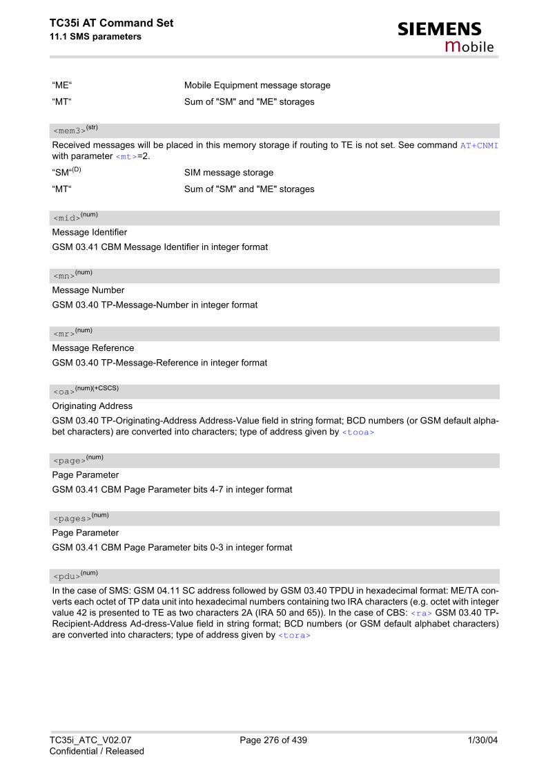
TC35i AT Command Set11.1 SMS parameters s
mobile
“ME“ Mobile Equipment message storage
“MT“ Sum of "SM" and "ME" storages
Received messages will be placed in this memory storage if routing to TE is not set. See command AT+CNMIwith parameter <mt>=2.
“SM“(D) SIM message storage
“MT“ Sum of "SM" and "ME" storages
Message IdentifierGSM 03.41 CBM Message Identifier in integer format
Message NumberGSM 03.40 TP-Message-Number in integer format
Message ReferenceGSM 03.40 TP-Message-Reference in integer format
Originating AddressGSM 03.40 TP-Originating-Address Address-Value field in string format; BCD numbers (or GSM default alpha-bet characters) are converted into characters; type of address given by <tooa>
Page ParameterGSM 03.41 CBM Page Parameter bits 4-7 in integer format
Page ParameterGSM 03.41 CBM Page Parameter bits 0-3 in integer format
In the case of SMS: GSM 04.11 SC address followed by GSM 03.40 TPDU in hexadecimal format: ME/TA con-verts each octet of TP data unit into hexadecimal numbers containing two IRA characters (e.g. octet with integervalue 42 is presented to TE as two characters 2A (IRA 50 and 65)). In the case of CBS: <ra> GSM 03.40 TP-Recipient-Address Ad-dress-Value field in string format; BCD numbers (or GSM default alphabet characters)are converted into characters; type of address given by <tora>
<mem3>(str)
<mid>(num)
<mn>(num)
<mr>(num)
<oa>(num)(+CSCS)
<page>(num)
<pages>(num)
<pdu>(num)
TC35i_ATC_V02.07 Page 276 of 439 1/30/04Confidential / Released

TC35i AT Command Set11.1 SMS parameters s
mobile
Recipient AddressGSM 03.40 TP-Recipient-Address Address-Value field in string format; BCD numbers (or GSM default alphabetcharacters) are converted to characters of the currently selected TE character set (refer to commandAT+CSCS.); type of address given by <tora>
Reference number to identify all segments of the concatenated SMS (i.e. the number needs to be the same foreach segment). If <ieia>=8 then max=255, otherwise 65535.
0...255
0...65535
Service Center AddressGSM 04.11 RP SC address Address-Value field in string format; BCD numbers (or GSM default alphabet char-acters) are converted to characters of the currently selected TE character set (refer to command AT+CSCS); typeof address given by <tosca>
Service Centre Time StampGSM 03.40 TP-Service-Centre-Time-Stamp in time-string format (refer <dt>)
Sequence number of the concatenated SMS beginning with 1. The number must be incremented by one foreach segment of the concatenated short message. <seq>=0 means: ignore the value. This will result in a non-concatenated SMS.
0...255
Serial NumberGSM 03.41 CBM Serial Number in integer format
StatusGSM 03.40 TP-Status in integer format
0...255
Message status3GPP 27.005 Interface of SMS and CB. Indicates the status of message in memory.
<ra>(num)(+CSCS)
<ref>(num)
<sca>(num)(+CSCS)
<scts>(num)
<seq>(num)
<sn>(num)
<st>(num)
<stat>(str)
TC35i_ATC_V02.07 Page 277 of 439 1/30/04Confidential / Released
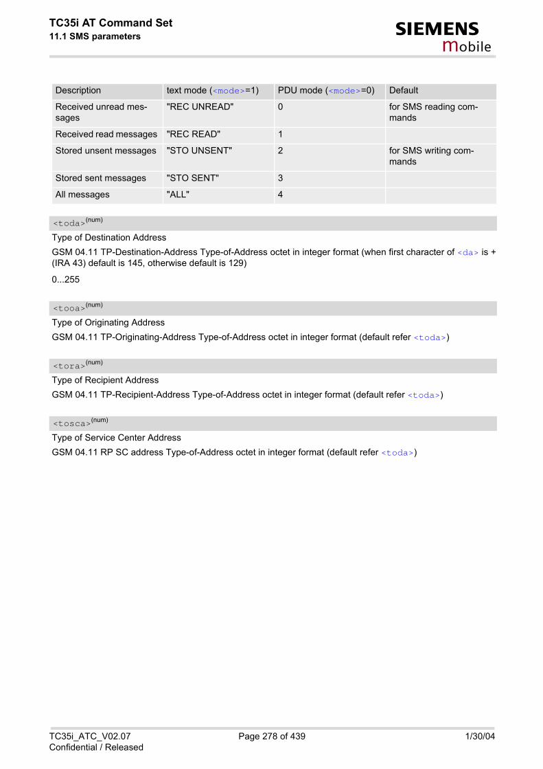
TC35i AT Command Set11.1 SMS parameters s
mobile
Type of Destination AddressGSM 04.11 TP-Destination-Address Type-of-Address octet in integer format (when first character of <da> is +(IRA 43) default is 145, otherwise default is 129)
0...255
Type of Originating AddressGSM 04.11 TP-Originating-Address Type-of-Address octet in integer format (default refer <toda>)
Type of Recipient AddressGSM 04.11 TP-Recipient-Address Type-of-Address octet in integer format (default refer <toda>)
Type of Service Center AddressGSM 04.11 RP SC address Type-of-Address octet in integer format (default refer <toda>)
Description text mode (<mode>=1) PDU mode (<mode>=0) Default
Received unread mes-sages
"REC UNREAD" 0 for SMS reading com-mands
Received read messages "REC READ" 1
Stored unsent messages "STO UNSENT" 2 for SMS writing com-mands
Stored sent messages "STO SENT" 3
All messages "ALL" 4
<toda>(num)
<tooa>(num)
<tora>(num)
<tosca>(num)
TC35i_ATC_V02.07 Page 278 of 439 1/30/04Confidential / Released

TC35i AT Command Set11.2 AT+CMGC s
mobile
11.2 AT+CMGC Send an SMS command
Syntax
Notes
• After invoking the commands AT+CMGW, AT+CMGS or AT+CMGC it is necessary to wait for the prompt ">"before entering text or PDU. After the prompt a timer will be started to observe the input.
• At baudrates below 19200 it is recommended to use the line termination character only (refer to ATS3, default<CR>) before entering the text or PDU. Use of the line termination character followed by the response format-ting character (refer to ATS4, default <LF> can cause problems
Test Command
AT+CMGC=?
Response(s)
OK
Write Command
If text mode (see AT+CMGF=1)
AT+CMGC=<fo>, <ct> [, <pid>[, <mn>[, <da>[, <toda>]]]] <CR> Text can be entered <CTRL-Z>/<ESC>
Response(s)
+CMGC: <mr>[, <scts>] If sending failsERROR+CMS ERROR
Write Command
If PDU mode (see AT+CMGF=0)
AT+CMGC=<length> <CR> PDU can be entered <CTRL-Z>/<ESC>
Response(s)
+CMGC: <mr>[, <ackpdu>] OKIf sending failsERROR+CMS ERROR
PIN ASC0 MUX1 MUX2 MUX3
� � � � �
Reference(s)
GSM 07.05
TC35i_ATC_V02.07 Page 279 of 439 1/30/04Confidential / Released

TC35i AT Command Set11.3 AT+CMGD s
mobile
11.3 AT+CMGD Delete SMS message
Syntax
Command Description
Write command deletes message from preferred message storage <mem1> location <index>.
Note
• If there is no SMS stored at the selected index, the response is OK too.
Test Command
AT+CMGD=?
Response(s)
OK
Write Command
AT+CMGD=<index>
Response(s)
OKERROR+CMS ERROR
PIN ASC0 MUX1 MUX2 MUX3
� � � � �
Reference(s)
GSM 07.05
TC35i_ATC_V02.07 Page 280 of 439 1/30/04Confidential / Released

TC35i AT Command Set11.4 AT+CMGF s
mobile
11.4 AT+CMGF Select SMS message format
Syntax
Command Description
The write command specifies the input and output format of the short messages.
Parameter Description
[0](&F) PDU mode
1 Text mode
Test Command
AT+CMGF=?
Response(s)
+CMGF: (list of supported<mode>s) OK
Read Command
AT+CMGF?
Response(s)
+CMGF: <mode> OK
Write Command
AT+CMGF=<mode>
Response(s)
OK
PIN ASC0 MUX1 MUX2 MUX3
� � � � �
Reference(s)
GSM 07.05
<mode>(num)(&W)(&V)
TC35i_ATC_V02.07 Page 281 of 439 1/30/04Confidential / Released

TC35i AT Command Set11.5 AT+CMGL s
mobile
11.5 AT+CMGL List SMS messages from preferred store
Syntax
Test Command
AT+CMGL=?
Response(s)
+CMGL: (list of supported <stat>s) OK
Exec Command
AT+CMGL
Response(s)
+CMGL: (see write command for default of <stat>) OK
Write Command
AT+CMGL=<stat>
Response(s)
Output if text mode (AT+CMGF=1) and command successful: For SMS- SUBMITs and/or SMS-DELIVERs +CMGL: <index>, <stat>, <oa>/<da>, [<alpha>] , [<scts>] [, <tooa>/<toda>, <length>] <data> [... ]OK
For SMS-STATUS-REPORTs +CMGL: <index>, <stat>, <fo>, <mr> , [<ra>] , [<tora>] , <scts>, <dt>, <st> [... ]OK
For SMS-Commands +CMGL: <index>, <stat>, <fo>, <ct> [... ]OK
Output if PDU mode AT+CMGF=0 and command successful: For SMS-SUBMITs and/or SMS-DELIVERs +CMGL: <index>, <stat>, [<alpha>], <length> <pdu> [... ]OK
If error is related to ME functionalityERROR +CMS ERROR
TC35i_ATC_V02.07 Page 282 of 439 1/30/04Confidential / Released

TC35i AT Command Set11.5 AT+CMGL s
mobile
Command Description
The execute command is the same as the write command with the given default for <stat>.
The write command returns messages with status value <stat> from message storage <mem1> to the TE. Ifstatus of the message is 'received unread', status in the storage changes to 'received read'.
Notes
• The selected <mem1> can contain different types of SMs (e.g. SMS-DELIVERs, SMS-SUBMITs, SMS-STA-TUS-REPORTs and SMS-COMMANDs), the response may be a mix of the responses of different SM types.TE application can recognize the response format by examining the third response parameter.
• The parameters <ra> and <tora> will only be displayed if parameter <ra> of the AT^SSCONF command isset to 1.
• Filler "FF" will not be displayed in PDU status reports if parameter <ff> of the AT^SSCONF command is setto 1.
• This command can be used only after the SMS data from the SIM have been read successfully for the firsttime. Reading starts after successful SIM authentication has been performed, and may take up to 30 secondsdepending on the SIM used. While the read process is in progress, an attempt to use any of the SMS readcommands will result in ''+CME Error: 14'' (SIM busy)
• We recommend to take advantage of the "^SSIM READY" URC. If enabled with AT^SSET, this URC acknowl-edges to the user that SIM data is accessible after SIM PIN authentication. It will be delivered once the MEhas completed reading data from the SIM card.
PIN ASC0 MUX1 MUX2 MUX3
� � � � �
Reference(s)
GSM 07.05
TC35i_ATC_V02.07 Page 283 of 439 1/30/04Confidential / Released
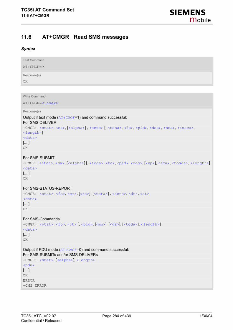
TC35i AT Command Set11.6 AT+CMGR s
mobile
11.6 AT+CMGR Read SMS messages
Syntax
Test Command
AT+CMGR=?
Response(s)
OK
Write Command
AT+CMGR=<index>
Response(s)
Output if text mode (AT+CMGF=1) and command successful: For SMS-DELIVER +CMGR: <stat>, <oa>, [<alpha>] , <scts> [, <tooa>, <fo>, <pid>, <dcs>, <sca>, <tosca>, <length>] <data> [... ]OK
For SMS-SUBMIT +CMGR: <stat>, <da>, [<alpha>] [, <toda>, <fo>, <pid>, <dcs>, [<vp>], <sca>, <tosca>, <length>] <data> [... ]OK
For SMS-STATUS-REPORT +CMGR: <stat>, <fo>, <mr>, [<ra>], [<tora>] , <scts>, <dt>, <st> <data> [... ]OK
For SMS-Commands +CMGR: <stat>, <fo>, <ct> [, <pid>, [<mn>], [<da>], [<toda>], <length>] <data> [... ]OK
Output if PDU mode (AT+CMGF=0) and command successful: For SMS-SUBMITs and/or SMS-DELIVERs +CMGR: <stat>, [<alpha>], <length> <pdu> [... ]OKERROR+CMS ERROR
TC35i_ATC_V02.07 Page 284 of 439 1/30/04Confidential / Released

TC35i AT Command Set11.6 AT+CMGR s
mobile
Command Description
The write command returns SMS message with location value <index> from message storage <mem1> to theTE. If status of the message is 'received unread', status in the storage changes to 'received read'.
Notes
• Response if AT+CMGR is used to read an empty record index: +CMGR: 0,,0
• Response if AT+CMGR is used to read a non-existent record index: +CMS ERROR: invalid memory index
• The parameters <ra> and <tora> will only be displayed if parameter <ra> of the AT^SSCONF command isset to 1.
• Filler "FF" will not be displayed in PDU status reports if parameter <ff> of the AT^SSCONF command is setto 1.
• This command can be used only after the SMS data from the SIM have been read successfully for the firsttime. Reading starts after successful SIM authentication has been performed, and may take up to 30 secondsdepending on the SIM used. While the read process is in progress, an attempt to use any of the SMS readcommands will result in ''+CME Error: 14'' (SIM busy)
• We recommend to take advantage of the "^SSIM READY" URC. If enabled with AT^SSET, this URC acknowl-edges to the user that SIM data is accessible after SIM PIN authentication. It will be delivered once the MEhas completed reading data from the SIM card.
PIN ASC0 MUX1 MUX2 MUX3
� � � � �
Reference(s)
GSM 07.05
TC35i_ATC_V02.07 Page 285 of 439 1/30/04Confidential / Released

TC35i AT Command Set11.7 AT+CMGS s
mobile
11.7 AT+CMGS Send SMS message
Syntax
Command Description
The write command transmits a short message from TE to network (SMS-SUBMIT).After invoking the write command wait for the prompt ">" and then start to write the message. To send the mes-sage simply enter <CTRL-Z>. After the prompt a timer will be started to observe the input.To abort sending use <ESC>. Abortion is acknowledged with "OK", though the message will not be sent.The message reference <mr> is returned to the TE on successful message delivery. The value can be used toidentify the message in a delivery status report provided as an unsolicited result code.
Notes
• If sending fails, for example, if a message is too long, the result code depends on the current setting of theAT^SM20 command:
Test Command
AT+CMGS=?
Response(s)
OK
Write Command
If text mode (see AT+CMGF=1)
AT+CMGS=<da>[, <toda>]<CR> Text can be entered. <CTRL-Z>/<ESC>
Response(s)
+CMGS: <mr>[, <scts>] OKIf sending fails see notes below.
Write Command
If PDU mode (see AT+CMGF=0) AT+CMGS=<length><CR> PDU can be entered. <CTRL-Z>/<ESC>
Response(s)
+CMGS: <mr>[, <ackpdu>] OKIf sending fails see notes below.
PIN ASC0 MUX1 MUX2 MUX3
� � � � �
Reference(s)
GSM 07.05
TC35i_ATC_V02.07 Page 286 of 439 1/30/04Confidential / Released

TC35i AT Command Set11.7 AT+CMGS s
mobile
If the AT^SM20 <CmgwMode> equals 1 (factory default) any failure to send a message is responded with "OK".Users should be aware, that despite the "OK" response, the message will not be sent to the subscriber.If the AT^SM20 <CmgwMode> equals 0 any failure to send a message is responded with "ERROR".
• If sending fails due to timeout, then AT^SM20 <CmgwMode>=1 causes "+CMS ERROR: Unknown error" to be returned;AT^SM20 <CmgwMode>=0 causes "+CMS ERROR: timer expired" to be returned.
• Note that some providers do not recognize an @ symbol used in a short message. A widely used alternativeis typing "*" as defined in GSM 03.40 (GPP TS 23.40).
• All characters entered behind the prompt ">" will be recognized as GSM characters. For example, "Back-space" (ASCII character 8) does not delete a character, but will be inserted into the short message as an addi-tional physical character. As a result, the character you wanted to delete still appears in the text, plus the GSMcode equivalent of the Backspace key.
• In text mode, the maximum length of an SMS depends on the used coding scheme: It is 160 characters if the7 bit GSM coding scheme is used, and 140 characters according to the 8 bit GSM coding scheme.
• At baudrates lower than 19200 it is recommended to use the line termination character only (refer to <n> ofATS3, default <CR>) before entering text or PDU. Use of the line termination character followed by theresponse formatting character (see <n> of ATS4, default <LF>) can cause problems.
TC35i_ATC_V02.07 Page 287 of 439 1/30/04Confidential / Released

TC35i AT Command Set11.8 AT+CMGW s
mobile
11.8 AT+CMGW Write SMS messages to memory
Syntax
Test Command
AT+CMGW=?
Response(s)
OK
Exec Command
If text mode (see AT+CMGF=1):
AT+CMGW
Response(s)
<CR> Text can be entered. <CTRL-Z>/<ESC> +CMGW: <index> OKIf writing failsERROR+CMS ERROR
Write Command
If text mode (see AT+CMGF=1): AT+CMGW=<oa>/<da> [, [<tooa>/<toda>][, <stat>]] <CR> Text can be entered. <CTRL-Z>/<ESC>
Response(s)
+CMGW: <index> OKIf writing fails see notes below.
Write Command
If PDU mode (see AT+CMGF=0):
AT+CMGW=<length> [, <stat>] <CR> PDU can be entered. <CTRL-Z>/<ESC>
Response(s)
+CMGW: <index> OKIf writing fails see notes below.
PIN ASC0 MUX1 MUX2 MUX3
� � � � �
Reference(s)
GSM 07.05
TC35i_ATC_V02.07 Page 288 of 439 1/30/04Confidential / Released

TC35i AT Command Set11.8 AT+CMGW s
mobile
Command Description
The execute and write commands transmit SMS (either SMS-DELIVER or SMS-SUBMIT) from TE to memorystorage <mem2>. Memory location <index> of the stored message is returned. Message status will be set to'stored unsent' unless otherwise given in parameter <stat>.After invoking the execute or write command wait for the prompt ">" and then start to write the message. To savethe message simply enter <CTRL-Z>. After the prompt a timer will be started to observe the input.To abort writing use <ESC>. Abortion is acknowledged with "OK", though the message will not be saved.
Notes
• If writing fails, for example, if a message is too long, the result code depends on the current setting of theAT^SM20 command:If the AT^SM20 <CmgwMode>=1 (factory default) any failure to send a message is responded with "OK". Usersshould be aware, that despite the "OK" response, the message will not be written to the selected SMS stor-age.If the AT^SM20 <CmgwMode> equals 0 any failure to write a message is responded with "ERROR".
• If writing fails due to timeout, then AT^SM20 <CmgwMode>=1 causes "+CMS ERROR: Unknown error" to be returned;AT^SM20 <CmgwMode>=0 causes "+CMS ERROR: timer expired" to be returned.
• Note that some providers do not recognize an @ symbol used in a short message. A widely used alternativeis typing "*" as defined in GSM 03.40 (GPP TS 23.40).
• For baudrates lower than 19200 it is recommended to use the line termination character only (refer to ATS3=<n>, default <CR>) before entering the text or PDU. Use of the line termination character followed by theresponse formating character (see ATS4= <n>, default <LF>) may cause problems.
• SMS-COMMANDs and SMS-STATUS-REPORTs cannot be stored in text mode.
• All characters entered behind the ">" prompt will be recognized as GSM characters. For example, "Back-space" (ASCII character 8) does not delete a character, but will be inserted into the short message as an addi-tional physical character. As a result, the character you wanted to delete still appears in the text, plus the GSMcode equivalent of the Backspace key.
• In text mode, the maximum length of an SMS depends on the used coding scheme: It is 160 characters if the7 bit GSM coding scheme is used, and 140 characters according to the 8 bit GSM coding scheme.
• The length of 8-bit data coded short messages has to be greater than 0.
TC35i_ATC_V02.07 Page 289 of 439 1/30/04Confidential / Released

TC35i AT Command Set11.9 AT+CMSS s
mobile
11.9 AT+CMSS Send SMS messages from storage
Syntax
Command Description
The write command sends message with location value <index> from message storage <mem2> to the network(SMS-SUBMIT or SMS-COMMAND). If new recipient address <da> is given for SMS-SUBMIT, it shall be usedinstead of the one stored with the message. Reference value <mr> is returned to the TE on successful messagedelivery. Value can be used to identify message upon unsolicited delivery status report result code.If the optional parameter <da> is given, the old status of the short message at <index> remains unchanged(see <stat>).
Test Command
AT+CMSS=?
Response(s)
OK
Write Command
If text mode (AT+CMGF=1):
AT+CMSS=<index> [, <da>[, <toda>]]
Response(s)
+CMSS: <mr>[, <scts>] OKIf sending failsERROR+CMS ERROR
Write Command
If PDU mode (AT+CMGF=0):
AT+CMSS=<index> [, <da>[, <toda>]]
Response(s)
+CMSS: <mr>[, <ackpdu>] OKIf sending failsERROR+CMS ERROR
PIN ASC0 MUX1 MUX2 MUX3
� � � � �
Reference(s)
GSM 07.05
TC35i_ATC_V02.07 Page 290 of 439 1/30/04Confidential / Released

TC35i AT Command Set11.10 AT+CNMA s
mobile
11.10 AT+CNMA New SMS message acknowledge to ME/TE, only phase 2+
Syntax
Command Description
The write / execute command confirms successful receipt of a new message (SMS-DELIVER or SMS-STATUS-REPORT) routed directly to the TE. TA shall not send another +CMT or +CDS result code to TE until previousone is acknowledged. If ME does not receive acknowledgment within required time (network time-out), ME sendsRP-ERROR to the network. TA shall automatically disable routing to TE by setting both <mt> and <ds> valuesof AT+CNMI to zero.
Parameter Description
0 Parameter is only required for PDU mode. Command operates similarly as intext mode
Test Command
AT+CNMA=?
Response(s)
+CNMA: (list of supported <n>s) OK
Exec Command
AT+CNMA
Response(s)
OKERROR+CMS ERROR
Write Command
AT+CNMA=<n>
Response(s)
OKERROR+CMS ERROR
PIN ASC0 MUX1 MUX2 MUX3
� � � � �
Reference(s)
GSM 07.05
<n>(num)
TC35i_ATC_V02.07 Page 291 of 439 1/30/04Confidential / Released

TC35i AT Command Set11.10 AT+CNMA s
mobile
Notes
• The execute / write command shall only be used when AT+CSMS parameter <service> equals 1 (= phase2+).
• Both the execute and the write command can be used no matter whether text mode or PDU mode is activated.
• If multiplex mode is activated (AT+CMUX=0) the AT+CNMI parameter will be set to zero on all channels, if onechannel fails to acknowledge an incoming message within the required time.
TC35i_ATC_V02.07 Page 292 of 439 1/30/04Confidential / Released

TC35i AT Command Set11.11 AT+CNMI s
mobile
11.11 AT+CNMI New SMS message indications
Syntax
Unsolicited Result Codes
URC 1
<mt>=1:
+CMTI: <mem3>, <index>
Indicates that new message has been received
URC 2
<mt>=2 (PDU mode enabled):
+CMT: <length><CR><LF><pdu>
Indicates that new message has been received
Test Command
AT+CNMI=?
Response(s)
+CNMI: (list of supported<mode>s), (list of supported<mt>s), (list of supported<bm>s), (list of supported<ds>s), (list of supported<bfr>s) OK
Read Command
AT+CNMI?
Response(s)
+CNMI: <mode>, <mt>, <bm>, <ds>, <bfr> OK
Write Command
AT+CNMI=[<mode>][, <mt>][, <bm>][, <ds>][, <bfr>]
Response(s)
OKERROR+CMS ERROR
PIN ASC0 MUX1 MUX2 MUX3
� � � � �
Reference(s)
GSM 07.05
TC35i_ATC_V02.07 Page 293 of 439 1/30/04Confidential / Released

TC35i AT Command Set11.11 AT+CNMI s
mobile
URC 3
<mt>=2 (text mode enabled):
+CMT: <oa>, <scts>[, <tooa>, <fo>, <pid>, <dcs>, <sca>, <tosca>, <length>]<CR><LF><data>
Indicates that new message has been received
URC 4
<bm>=2 (PDU mode enabled): +CBM: <length><CR><LF><pdu>
Indicates that new cell broadcast message has been received
URC 5
<bm>=2 (text mode enabled):
+CBM: <sn>, <mid>, <dcs>, <page>, <pages><CR><LF><data>
Indicates that new cell broadcast message has been received
URC 6
<ds>=1 (PDU mode enabled):
+CDS: <length><CR><LF><pdu>
Indicates that new SMS status report has been received
URC 7
<ds>=1 (text mode enabled):
+CDS: <fo>, <mr>[, <ra>][, <tora>], <scts>, <dt>, <st>
Indicates that new SMS status report has been received
URC 8
<ds>=2: +CDSI: <mem3>, <index>
Indicates that new SMS status report has been received
Command Description
The write command selects the procedure how the receipt of new SMS messages from the network is indicatedto the TE when TE is active, e.g. DTR signal is ON. If TE is inactive (e.g. DTR signal is OFF), message receivingshould be done as specified in GSM 03.38. If the DTR signal is not available or the state of the signal is ignored(V.25ter command AT&D0), reliable message transfer can be ensured by using AT+CNMA acknowledgment pro-cedure.
Parameter Description
[0](&F) Buffer unsolicited result codes in the TA. If TA result code buffer is full, indica-tions can be buffered in some other place or the oldest indications may be dis-carded and replaced with the new received indications.
1 Discard indication and reject new received message unsolicited result codeswhen TA-TE link is reserved (e.g. in on-line data mode). Otherwise forwardthem directly to the TE.
<mode>(num)(&W)(&V)
TC35i_ATC_V02.07 Page 294 of 439 1/30/04Confidential / Released

TC35i AT Command Set11.11 AT+CNMI s
mobile
2 Buffer unsolicited result codes in the TA when TA-TE link is reserved (e.g. inon-line data mode) and flush them to the TE after reservation. Otherwise for-ward them directly to the TE.
3 Forward unsolicited result codes directly to the TE. TA-TE link specific inbandtechnique used to embed result codes and data when TA is in on-line datamode.
Rules for storing received SMS depend on the relevant data coding method (refer to GSM 03.38), preferredmemory storage (AT+CPMS) setting and this value.Note: If AT command interface is acting as the only display device, the ME must support storage of class 0 mes-sages and messages in the message waiting indication group (discard message)
[0](&F) No SMS-DELIVER indications are routed to the TE.
1 If SMS-DELIVER is stored in ME/TA, indication of the memory location isrouted to the TE using unsolicited result code.
2 SMS-DELIVERs, except class 2 messages and messages in the messagewaiting indication group (store message) are routed directly to the TE usingunsolicited result code.
3 Class 3 SMS-DELIVERs are routed directly to the TE using unsolicited resultcodes defined in <mt>=2. Messages of other data coding schemes result inindication as defined in <mt>=1.
Rules for storing received CBMs depend on the relevant data coding method (refer to GSM 03.38), the settingof Select CBM Types (AT+CSCB) and this value:
[0](&F) No CBM indications are routed to the TE.
2 New CBMs are routed directly to the TE using unsolicited result code.
3 Class 3 CBMs are routed directly to TE using unsolicited result codes definedin <bm>=2.
[0](&F) No SMS-STATUS-REPORTs are routed to the TE.
1 SMS-STATUS-REPORTs are routed to the TE using unsolicited result code.
2 If SMS-STATUS-REPORT is routed into ME/TA, indication of the memorylocation is routed to the TE using unsolicited result code.
[1](&F) TA buffer of unsolicited result codes defined within this command is clearedwhen <mode> 1...3 is entered.
Integer type; value in the range of location numbers supported by the associated memory
Notes
• Each time an SMS or Cell Broadcast Message is received, the Ring Line goes Logic "1" for one second.
<mt>(num)(&W)(&V)
<bm>(num)(&W)(&V)
<ds>(num)(&W)(&V)
<bfr>(num)(&W)(&V)
<index>(num)
TC35i_ATC_V02.07 Page 295 of 439 1/30/04Confidential / Released

TC35i AT Command Set11.11 AT+CNMI s
mobile
• Requirements specific to Multiplex mode:In multiplex mode (AT+CMUX=0) only one channel can use a phase 2+ parameter. The parameter for <mt>and <ds> on the other channels have to be set to zero. If either a SM or a Status Report is not acknowledged,all AT+CNMI parameter in all channels will be set to zero.
• Handling of Class 0 short messages:If the host application is provided with a display and AT^SSDA=1 has been set Class 0 short messages canbe displayed immediately.If the host application does not include a display, ME handles Class 0 short messages as though there wasno message class, i.e. it will ignore bits 0 and 1 in the <dcs> and normal rules for exceeded memory capacityshall apply. This approach is compliant with GSM 03.38 .
• The parameters <ra> and <tora> will only be displayed if <ra> of the AT^SSCONF command is set to 1.
• Filler "FF" will not be displayed in PDU status reports if the parameter <ff> of AT^SSCONF command is setto 1.
• If either a SM or a Status Report is not acknowledged, all AT+CNMI parameters in all channels will be set tozero.
• If the ME operates on different instances (MUX channels 1, 2, 3) avoid different settings for routing and indi-cating SMS. For example, if messages shall be routed directly to one instance of the TE (set with AT+CNMI,AT^SSDA), it is not possible to activate the presentation of URCs with AT+CMER or AT+CNMI on anotherinstance. Any attempt to activate settings that conflict with existing settings on another interface, will result inCME ERROR, or accordingly CMS ERROR.
TC35i_ATC_V02.07 Page 296 of 439 1/30/04Confidential / Released

TC35i AT Command Set11.12 AT+CPMS s
mobile
11.12 AT+CPMS Preferred SMS message storage
Syntax
Command Description
Thewrite command selects memory storages <mem1>,<mem2>, <mem3> to be used for reading, writing, etc.
Parameter Description
Number of messages currently in <mem1>
Test Command
AT+CPMS=?
Response(s)
+CPMS: (list of supported <mem1>s), (list of supported <mem2>s), (list of supported <mem3>s) OK
Read Command
AT+CPMS?
Response(s)
+CPMS: <mem1>, <used1>, <total1>, <mem2>, <used2>, <total2>, <mem3>, <used3>, <total3> OKERRORERROR+CMS ERROR
Write Command
AT+CPMS=<mem1>[, <mem2>[, <mem3>]]
Response(s)
+CPMS: <used1>, <total1>, <used2>, <total2>, <used3>, <total3> OKERRORERROR+CMS ERROR
PIN ASC0 MUX1 MUX2 MUX3
� � � � �
Reference(s)
GSM 07.05
<used1>(num)
TC35i_ATC_V02.07 Page 297 of 439 1/30/04Confidential / Released

TC35i AT Command Set11.12 AT+CPMS s
mobile
Number of messages currently in <mem2>
Number of messages currently in <mem3>
Number of messages storable in <mem1>
Number of messages storable in <mem2>
Number of messages storable in <mem3>
Notes
• The Mobile Equipment storage ''ME'' offers space for 25 short messages, see <mem1>.
• ''MT'' is the sum of ''ME'' (= 25 locations) and ''SM'' (capacity varies with SIM card). The indices <index> ofthe ''MT'' storage are dependent on the order selected with AT^SSMSS
• The <mem1>, <mem2> and <mem3> parameter will be stored in non-volatile memory.
• The user should be aware that the setting ''MT'' involves ''ME'' and ''SM'', with ''ME'' being filled up first. If the''ME'' storage is full, TC35i will proceed with the ''SM'' storage. Incoming Class 1 short messages (ME specific) will be preferably stored to ''ME'' and may be transferred tothe ''SM'' storage if ''ME'' is used up. Incoming Class 2 messages (SIM specific) will be stored to the SIM card only, no matter whether or not thereis free ''ME'' space. As a result, the ^SMGO: 2 indication (see AT^SMGO) may be presented without prior indi-cation of ^SMGO: 1. For more information regarding SIM and ME specific message classes refer to <dcs>and the following specifications: GSM 03.38 and 3GPP TS23038.
• When <mem3> is switched over from ''MT'' to ''SM'' all free ''ME'' locations will be filled with dummy short mes-sages. This procedure can take up to 35 seconds, until all the 25 records are written. If switching from ''MT'' to ''SM'' was not finished due to error or user break, the value of <mem3> remains ''MT'',but some of the dummy records remain in the ''ME'' storage. These records have to be deleted manually.When <mem3> equals ''SM'', do not delete the dummy messages in the ''ME''. storage. They will be automat-ically deleted when you switch back from ''SM'' to ''MT''. Again, this may take up to 35 seconds. If switching from ''SM'' to ''MT'' was not finished due to an error or user break, the value of <mem3> remains''SM'', but the ''ME'' storage will no longer be filled with dummy records. New incoming short messages maynow be written to the ''ME'' storage, if ''SM'' is already full. To avoid this, repeat the AT+CPMS command assoon as possible to switch <mem3> back to ''MT''. As an alternative, you can manually delete the dummyrecords and issue AT+CPMS=MT,MT,MT.
• Multiplexer: In Multiplex mode or when the two physical serial interfaces are connected, the parameter<mem3> will be the same on all instances, but the settings of <mem1> and <mem2> may vary on each channel/ interface. As a result, changes on parameter <mem1> and/or <mem2> befor activating the multiplexer or dif-ferences values for other instanes can result in not desired behaviours like different outputs for AT+CMGL andso on.
• While <mem3> equals ''SM'' and <mem1> equals ''ME'' it is possible that, after deleting short messages from''ME'', the freed space on ''ME'' is reclaimed for new incoming short messages, when there is no space left onthe ''SM'' storage. As it is often the clients concern to have received short messages stored only to the SIM
<used2>(num)
<used3>(num)
<total1>(num)
<total2>(num)
<total3>(num)
TC35i_ATC_V02.07 Page 298 of 439 1/30/04Confidential / Released

TC35i AT Command Set11.12 AT+CPMS s
mobile
card, inconsistent settings should be generally avoided. This can be achieved simply by using the sameparameter for all memory indices.
• The indices <index> of the storage are dependent on the order selected with AT^SSMSS.
TC35i_ATC_V02.07 Page 299 of 439 1/30/04Confidential / Released

TC35i AT Command Set11.13 AT+CSCA s
mobile
11.13 AT+CSCA SMS service centre address
Syntax
Command Description
Write command updates the SMSC address, through which mobile originated SMs are transmitted. In text mode,setting is used by send and write commands. In PDU mode, setting is used by the same commands, but onlywhen the length of the SMSC address coded into <pdu> parameter equals zero.
Notes
• In case of using no parameter after AT+CSCA= the content of <sca> will be deleted
• This command writes the service centre address to non-volatile memo
• The SMS service centre address should be entered as specified by the service provider
Test Command
AT+CSCA=?
Response(s)
OK
Read Command
AT+CSCA?
Response(s)
+CSCA: <sca>, <tosca> OK
Write Command
AT+CSCA=<sca>[, <tosca>]
Response(s)
OK
PIN ASC0 MUX1 MUX2 MUX3
� � � � �
Reference(s)
GSM 07.05
TC35i_ATC_V02.07 Page 300 of 439 1/30/04Confidential / Released

TC35i AT Command Set11.14 AT+CSCB s
mobile
11.14 AT+CSCB Select Cell Broadcast Message Indication
Syntax
Command Description
Test command returns supported modes as a compound value.
Write command selects which types of CBMs are to be received by the ME.
Parameter Description
Message mode
[0] Accept messages that are defined in <mids> and <dcss>
1 Forbid messages that are defined in <mids> and <dcss>
Cell Broadcast Message ID specification
Test Command
AT+CSCB=?
Response(s)
+CSCB: (list of supported <mode>s) OK
Read Command
AT+CSCB?
Response(s)
+CSCB: <mode>, <mids>, <dcss> OK
Write Command
AT+CSCB=[<mode>[, <mids>[, <dcss>]]]
Response(s)
OK
PIN ASC0 MUX1 MUX2 MUX3
� � � � �
Reference(s)
GSM 07.05
<mode>(num)
<mids>(str)
TC35i_ATC_V02.07 Page 301 of 439 1/30/04Confidential / Released

TC35i AT Command Set11.14 AT+CSCB s
mobile
• For <mode>=0: Six different possible combinations of CBM IDs (e.g. "0,1,5,320-478,922,2000-3000"), defaultis empty string. In certain configurations, e.g. if using SIMs that contain data in Elementary File EF-CBMID (Cell BroadcastMessage Identifier for Data download) less than six combinations may be available. To access a SIM's Elementary File data refer to command AT+CRSM.
• For <mode>=1: One CBM ID or range of IDs (e.g. "320-478"), default is empty string.
CBM data coding scheme specificationAll different possible combinations of CBM data coding schemes (e.g. "0-3,5"). Using default empty string leadsto get all CBMs independent of their dcss. A given <dcss> replaces any former value and is used for consecutive requests.
<dcss>(str)
TC35i_ATC_V02.07 Page 302 of 439 1/30/04Confidential / Released

TC35i AT Command Set11.15 AT+CSDH s
mobile
11.15 AT+CSDH Show SMS text mode parameters
Syntax
Command Description
Write command sets whether or not detailed header information is shown in text mode result codes.
Parameter Description
[0](&F) Do not show header values defined in commands AT+CSCA and AT+CSMP(<sca>, <tosca>,<fo>,<vp>, <pid> and <dcs>) nor <length>, <toda> or<tooa> in "+CMTI", AT+CMGL, AT+CMGR result codes for SMS-DELIVERs andSMS-SUBMITs in text mode; for SMS-COMMANDs in +CMGR result code, donot show <pid>,<mn>,<da>, <toda>, <length> or <cdata>
1 Show the values in result codes
Test Command
AT+CSDH=?
Response(s)
+CSDH: ((list of supported <show>s) OK
Read Command
AT+CSDH?
Response(s)
+CSDH:<show> OK
Write Command
AT+CSDH=<show>
Response(s)
+CSDH: <show> OK
PIN ASC0 MUX1 MUX2 MUX3
� � � � �
Reference(s)
GSM 07.05
<show>(num)(&W)
TC35i_ATC_V02.07 Page 303 of 439 1/30/04Confidential / Released

TC35i AT Command Set11.16 AT+CSMP s
mobile
11.16 AT+CSMP Set SMS text mode parameters
Syntax
Command Description
The write command selects values for additional parameters needed when SM is sent to the network or placedin a storage when text format message mode is selected. It is possible to set the validity period starting from when the SM is received by the SMSC (<vp> is in range 0...255) or define the absolute time of the validity period termination (<vp> is a string). The format of <vp> is givenby <fo>. If TA supports the enhanced validity period format, see GSM 03.40), it shall be given as a hexadecimalcoded string (e.g. <pdu>) with quotes.
Test Command
AT+CSMP=?
Response(s)
OK
Read Command
AT+CSMP?
Response(s)
+CSMP:<fo>, <vp>/ <scts>, <pid>, <dcs> OK
Write Command
AT+CSMP=<fo> [, <vp>/<scts>[, <pid>[, <dcs>]]]
Response(s)
+CSMP: <index> OKIf sending failsERROR+CMS ERROR
PIN ASC0 MUX1 MUX2 MUX3
� � � � �
Reference(s)
GSM 07.05
TC35i_ATC_V02.07 Page 304 of 439 1/30/04Confidential / Released

TC35i AT Command Set11.16 AT+CSMP s
mobile
Parameter Description
First Octetdepending on the command or result code: first octet of GSM 03.40 SMS-DELIVER, SMS-SUBMIT (default 17),SMS-STATUS-REPORT, or SMS-COMMAND (default 2) in integer format
0...17(&F)...255
Depending on SMS-SUBMIT <fo> setting: GSM 03.40 TP-Validity-Period either in integer format or in time-string format (refer <dt>)
0...167(&F)...255
Data Coding SchemeGSM 03.38 SMS Data Coding Scheme, or Cell Broadcast Data Coding Scheme in integer format
0(&F)...247
Protocol IdentifierGSM 03.40 TP-Protocol-Identifier in integer format
0(&F)...255
Notes
• When storing a SMS DELIVER from the TE to the preferred memory storage in text mode (using the AT+CMGWwrite command), <vp> field can be used for <scts>.
• The command writes the parameters to the non-volatile memory.
<fo>(num)
<vp>(num)
<dcs>(num)
<pid>(num)
TC35i_ATC_V02.07 Page 305 of 439 1/30/04Confidential / Released

TC35i AT Command Set11.17 AT+CSMS s
mobile
11.17 AT+CSMS Select Message Service
Syntax
Parameter Description
0 GSM 03.40 and GSM 03.41 (the syntax of SMS AT commands is compatiblewith GSM 07.05 Phase 2 version 4.7.0; Phase 2+ features which do not requirenew command syntax may be supported, e.g. correct routing of messages withnew Phase 2+ data coding schemes)
1 GSM 03.40 and GSM 03.41 (the syntax of SMS AT commands is compatiblewith GSM 07.05 Phase 2+ version; the requirement of <service> setting 1 ismentioned under corresponding command descriptions).
Test Command
AT+CSMS=?
Response(s)
+CSMS: (list of supported<service>s) OK
Read Command
AT+CSMS?
Response(s)
+CSMS: <service>, <mt>, <mo>, <bm> OK
Write Command
AT+CSMS=<service>
Response(s)
+CSMS: <mt>, <mo>, <bm> OKERROR+CMS ERROR
PIN ASC0 MUX1 MUX2 MUX3
� � � � �
Reference(s)
GSM 07.05
<service>(num)
TC35i_ATC_V02.07 Page 306 of 439 1/30/04Confidential / Released

TC35i AT Command Set11.17 AT+CSMS s
mobile
Mobile Terminated Messages:
0 Type not supported
1 Type supported
Mobile Originated Messages:
0 Type not supported
1 Type supported
Broadcast Type Messages:
0 Type not supported
1 Type supported
Note
• If CSMS is switched to <service>= 1, all messages with phase 2+ (see AT+CNMI with mt= 2, mt= 3, ds= 1)have to be acknowledged with AT+CNMA.
<mt>(num)
<mo>(num)
<bm>(num)
TC35i_ATC_V02.07 Page 307 of 439 1/30/04Confidential / Released

TC35i AT Command Set11.18 AT^SCML s
mobile
11.18 AT^SCML List Concatenated SMS messages from preferred store
Syntax
Test Command
AT^SCML=?
Response(s)
^SCML: (list of supported <stat>s) OK
Exec Command
AT^SCML
Response(s)
^SCML: (see write command for default of <stat>) OK
Write Command
AT^SCML=<stat>
Response(s)
Output if text mode (AT+CMGF=1) and command successful: For SMS-SUBMITs and/or SMS-DELIVERs ^SCML: <index>, <stat>, <oa>/<da>, [<alpha>] , [<scts>] [, <tooa>/<toda>, <length>] [, <seq>, <max>, <ieia>, <ref>] <data> [... ]OK
For SMS-STATUS-REPORTs ^SCML: <index>, <stat>, <fo>, <mr> , [<ra>] , [<tora>] , <scts>, <dt>, <st> [... ]OK
For SMS-Commands ^SCML: <index>, <stat>, <fo>, <ct> [... ]OK
Output if PDU mode (AT+CMGF=0) and command successful: For SMS- SUBMITs and/or SMS-DELIVERs ^SCML: <index>, <stat>, [<alpha>], <length> <pdu> [... ]OK
If error is related to ME functionality
TC35i_ATC_V02.07 Page 308 of 439 1/30/04Confidential / Released

TC35i AT Command Set11.18 AT^SCML s
mobile
Command Description
The execute command is the same as the write command with the given default for <stat>.
The write command returns messages with status value <stat> from message storage <mem1> to the TE. Ifstatus of the message is 'received unread', status in the storage changes to 'received read'.
Note
• See notes of AT+CMGL.
ERROR +CMS ERROR
PIN ASC0 MUX1 MUX2 MUX3
� � � � �
Reference(s)
SIEMENS
Write Command (Continued)
AT^SCML=<stat>
Response(s)
TC35i_ATC_V02.07 Page 309 of 439 1/30/04Confidential / Released

TC35i AT Command Set11.19 AT^SCMR s
mobile
11.19 AT^SCMR Read concatenated SMS messages
Syntax
Test Command
AT^SCMR=?
Response(s)
OK
Write Command
AT^SCMR=<index>
Response(s)
Output if text mode (AT+CMGF=1) and command successful: For SMS-DELIVER ^SCMR: <stat>, <oa>, [<alpha>] , <scts> [, <tooa>, <fo>, <pid>, <dcs>, <sca>, <tosca>, <length>] [, <seq>, <max>, <ieia>, <ref>] <data> [... ]OK
For SMS-SUBMIT ^SCMR: <stat>, <da>, [<alpha>] [, <toda>, <fo>, <pid>, <dcs>, [<vp>], <sca>, <tosca>, <length>] [, <seq>, <max>, <ieia>, <ref>] <data> [... ]OK
For SMS-STATUS-REPORT ^SCMR: <stat>, <fo>, <mr>, [<ra>], [<tora>] , <scts>, <dt>, <st> <data> [... ]OK
For SMS-Commands ^SCMR: <stat>, <fo>, <ct> [, <pid>, [<mn>], [<da>], [<toda>], <length>] <data> [... ]OK
Output if PDU mode (AT+CMGF=0) and command successful: For SMS-SUBMITs and/or SMS-DELIVERs ^SCMR: <stat>, [<alpha>], <length> <pdu> [... ]OK
ERROR+CMS ERROR
TC35i_ATC_V02.07 Page 310 of 439 1/30/04Confidential / Released

TC35i AT Command Set11.19 AT^SCMR s
mobile
Command Description
The write command returns SMS message with location value <index> from message storage <mem1> to theTE. If status of the message is 'received unread', status in the storage changes to 'received read'.
Note
• See notes of AT+CMGR
PIN ASC0 MUX1 MUX2 MUX3
� � � � �
Reference(s)
SIEMENS
TC35i_ATC_V02.07 Page 311 of 439 1/30/04Confidential / Released

TC35i AT Command Set11.20 AT^SCMS s
mobile
11.20 AT^SCMS Send concatenated SMS messages
Sending a concatenated message is similar to sending a "normal" message, except that each segment of theconcatenated message must be identified by the additional parameters <seq>, <ieia> and <ref>. To send allsegments of the message one by one, the AT^SCMS write command must be executed for each segment.
Syntax
Command Description
The write command transmits one segment of a concatenated short message from TE to network (SMS-SUB-MIT).After invoking the write command wait for the prompt ">" and then start to write the message. To send the mes-sage simply enter <CTRL-Z>. After the prompt a timer will be started to observe the input.To abort sending use <ESC>. Abortion is acknowledged with "OK", though the message will not be sent.The message reference <mr> is returned to the TE on successful message delivery. The value can be used toidentify the message in a delivery status report provided as an unsolicited result code.
Notes
• See notes provided for AT+CMGS.
• Command is only available if AT+CMGF=1.
Test Command
AT^SCMS=?
Response(s)
OK
Write Command
Command syntax for text mode (see AT+CMGF=1):
AT^SCMS=<da>[, <toda>], <seq>, <max>, <ieia>, <ref><CR> Text can be entered <CTRL-Z>/<ESC>
Response(s)
+CMGS: <mr>[, <scts>] OKIf sending failsERROR+CMS ERROR
PIN ASC0 MUX1 MUX2 MUX3
� � � � �
Reference(s)
SIEMENS
TC35i_ATC_V02.07 Page 312 of 439 1/30/04Confidential / Released

TC35i AT Command Set11.21 AT^SCMW s
mobile
11.21 AT^SCMW Write concatenated SMS messages to memory
Writing a concatenated message to the memory is similar to writing a "normal" message, except that each seg-ment of the concatenated message must be identified by the additional parameters <seq>, <ieia> and <ref>.To store all segments of the message one by one, the AT^SCMW write command must be executed for each seg-ment.
Syntax
Command Description
The write commands transmits one segment of a concatenated SMS (either SMS-DELIVER or SMS-SUBMIT)from TE to memory storage <mem2>. Memory location <index> of the stored message is returned. Messagestatus will be set to 'stored unsent' unless otherwise given in parameter <stat>.
Notes
• Command is only available if AT+CMGF=1.
• To send or delete a concatenated short message please use the known SMS commands, see AT+CMSS forsending and AT+CMGD for deleting.
• See notes provided for AT+CMGW.
Test Command
AT^SCMW=?
Response(s)
OK
Write Command
If text mode (see AT+CMGF=1)
AT^SCMW=<oa>/<da>, [<tooa>/<toda>][, <stat>] , <seq>, <max>, <ieia>, <ref> <CR> Text can be entered. <CTRL-Z>/<ESC>
Response(s)
^SCMW: <index> OKIf writing failsERROR+CMS ERROR
PIN ASC0 MUX1 MUX2 MUX3
� � � � �
Reference(s)
SIEMENS
TC35i_ATC_V02.07 Page 313 of 439 1/30/04Confidential / Released

TC35i AT Command Set11.22 AT^SLMS s
mobile
11.22 AT^SLMS List SMS Memory Storage
Syntax
Command Description
The execute command indicates the maximum capacity of each SMS storage type and the number of locationscurrently used.
Parameter Description
Maximum number of messages storable in the SMS memory of the SIM (physical storage "SM")
Maximum number of messages storable in the SMS memory of the Mobile Equipment (physical storage "ME")
Sum of "SM" and "ME", indicated as "MT". Maximum number of all messages storable in the SIM memory andthe Mobile Equipment memory.
Number of messages currently stored in the SMS memory of the SIM (physical storage "SM")
Test Command
AT^SLMS=?
Response(s)
OK
Exec Command
AT^SLMS
Response(s)
^SLMS: ''MT'',<total3>, <used3> ^SLMS: ''SM'',<total1>, <used1> ^SLMS: ''ME'',<total2>, <used2> OKERROR+CMS ERROR
PIN ASC0 MUX1 MUX2 MUX3
� � � � �
Reference(s)
SIEMENS
<total1>(num)
<total2>(num)
<total3>(num)
<used1>(num)
TC35i_ATC_V02.07 Page 314 of 439 1/30/04Confidential / Released

TC35i AT Command Set11.22 AT^SLMS s
mobile
Number of messages currently stored in the SMS memory of the Mobile Equipment (physical storage "ME")
Concatenated logical SMS storages of SIM ("SM") and Mobile Equipment ("ME"). Sum of all messages currentlystored, indicated as "MT".
<used2>(num)
<used3>(num)
TC35i_ATC_V02.07 Page 315 of 439 1/30/04Confidential / Released

TC35i AT Command Set11.23 AT^SMGL s
mobile
11.23 AT^SMGL List SMS messages from preferred store without set-ting status to REC READ
Syntax
Command Description
The execute command is the same as the write command, but uses the given default of <stat>.
The write command allows to select a status type and lists, from the message storage <mem1>, all messagesthat currently have the specified <stat>. The major difference over the standard command AT+CMGL is that thestatus of the listed messages remains u n c h a n g e d (unread remains unread).
Notes
• The selected <mem1> can contain different types of SMs (e.g. SMS-DELIVERs, SMS-SUBMITs, SMS-STA-TUS-REPORTs and SMS-COMMANDs), the response may be a mix of the responses of different SM types.TE application can recognize the response format by examining the third response parameter.
• This command can be used only after the SMS data from the SIM have been read successfully for the firsttime. Reading starts after successful SIM authentication has been performed, and may take up to 30 secondsdepending on the SIM used. While the read process is in progress, an attempt to use any of the sms readcommands will result in ''+CME Error: 14'' (SIM busy)
Test Command
AT^SMGL=?
Response(s)
same as AT+CMGL
Exec Command
AT^SMGL
Response(s)
^SMGL: (For default values of <stat>, see Chapter "SMS parameters.) OK
Write Command
AT^SMGL=<stat>
Response(s)
same as AT+CMGL
PIN ASC0 MUX1 MUX2 MUX3
� � � � �
Reference(s)
SIEMENS
TC35i_ATC_V02.07 Page 316 of 439 1/30/04Confidential / Released
TC35i AT Command Set11.23 AT^SMGL s
mobile
• We recommend to take advantage of the "^SSIM READY" URC. If enabled with AT^SSET, this URC acknowl-edges to the user that SIM data is accessible after SIM PIN authentication. It will be delivered once the MEhas completed reading data from the SIM card.
TC35i_ATC_V02.07 Page 317 of 439 1/30/04Confidential / Released

TC35i AT Command Set11.24 AT^SMGO s
mobile
11.24 AT^SMGO Set or query SMS overflow presentation mode or query SMS overflow
Syntax
Unsolicited Result Code
SMS buffer change: ^SMGO: <mode>
Status of SMS buffer has changed.
Command Description
The read command returns overflow presentation mode and SMS overflow status
The write command sets overflow presentation mode
Test Command
AT^SMGO=?
Response(s)
^SMGO: (list of supported<n>s) OK
Read Command
AT^SMGO?
Response(s)
^SMGO: <n>, <mode> OKERROR+CMS ERROR
Write Command
AT^SMGO=<n>
Response(s)
OKERRORCME ERROR
PIN ASC0 MUX1 MUX2 MUX3
� � � � �
Reference(s)
SIEMENS
TC35i_ATC_V02.07 Page 318 of 439 1/30/04Confidential / Released

TC35i AT Command Set11.24 AT^SMGO s
mobile
Parameter Description
SMS overflow presentation mode
[0](&F) disable
1 enable
SMS overflow status
0 space available
1 SMS buffer full (The buffer for received short messages is <mem3>. SeeAT+CPMS.)
2 Buffer full and new message waiting in SC for delivery to phone
Notes
• Incoming short messages with message class 1 (ME specific short messages) or class 2 (SM specific shortmessages), see <dcs> in GSM 03.38, will be stored either in ''ME'' or in ''SM'' storage. Therefore the"^SMGO:2" indication could occur, without issuing the indication "^SMGO:1" before. The indication "^SMGO:1"means that both buffers (''ME'' and ''SM'') are full.
• For more information regarding SIM and ME specific message classes refer to <dcs> and the following spec-ifications: GSM 03.38 and 3GPP TS 23.038 .
<n>(num)(&W)(&V)
<mode>(num)(&V)
TC35i_ATC_V02.07 Page 319 of 439 1/30/04Confidential / Released

TC35i AT Command Set11.25 AT^SMGR s
mobile
11.25 AT^SMGR Read SMS message without setting status to REC READ
Syntax
Notes
• The AT^SMGR command is a specific Siemens command with the same syntax as AT+CMGR Read SMS mes-sage. The only difference is that the status ''REC UNREAD'' of a short message is not overwritten to ''RECREAD''.
• This command can be used only after the sms data from the SIM have been read successfully for the firsttime. Reading starts after successful SIM authentication has been performed, and may take up to 30 secondsdepending on the SIM used. While the read process is in progress, an attempt to use any of the sms readcommands will result in ''+CME Error: 14'' (SIM busy)
• We recommend to take advantage of the "^SSIM READY" URC. If enabled with AT^SSET, this URC acknowl-edges to the user that SIM data is accessible after SIM PIN authentication. It will be delivered once the MEhas completed reading data from the SIM card.
Test Command
AT^SMGR=?
Response(s)
^SMGR: OK
Write Command
AT^SMGR=<index>
Response(s)
see AT+CMGR
PIN ASC0 MUX1 MUX2 MUX3
� � � � �
Reference(s)
SIEMENS
TC35i_ATC_V02.07 Page 320 of 439 1/30/04Confidential / Released
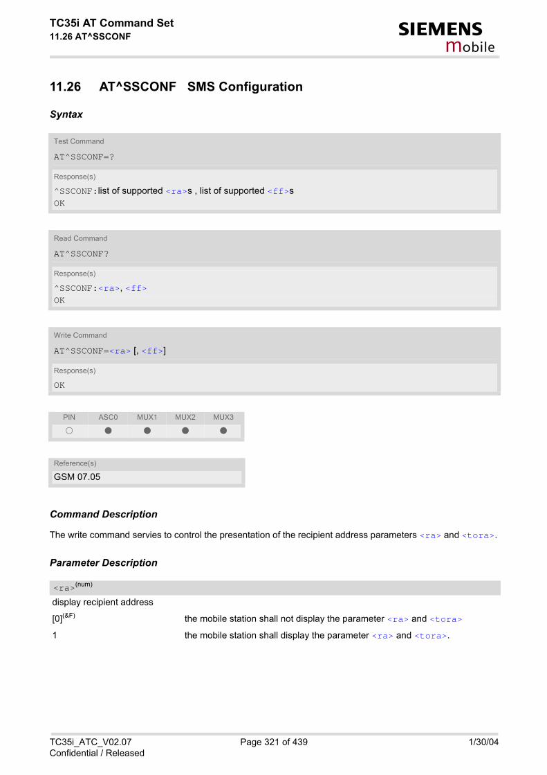
TC35i AT Command Set11.26 AT^SSCONF s
mobile
11.26 AT^SSCONF SMS Configuration
Syntax
Command Description
The write command servies to control the presentation of the recipient address parameters <ra> and <tora>.
Parameter Description
display recipient address
[0](&F) the mobile station shall not display the parameter <ra> and <tora>
1 the mobile station shall display the parameter <ra> and <tora>.
Test Command
AT^SSCONF=?
Response(s)
^SSCONF:list of supported <ra>s , list of supported <ff>s OK
Read Command
AT^SSCONF?
Response(s)
^SSCONF:<ra>, <ff> OK
Write Command
AT^SSCONF=<ra> [, <ff>]
Response(s)
OK
PIN ASC0 MUX1 MUX2 MUX3
� � � � �
Reference(s)
GSM 07.05
<ra>(num)
TC35i_ATC_V02.07 Page 321 of 439 1/30/04Confidential / Released

TC35i AT Command Set11.26 AT^SSCONF s
mobile
display filler bits
[0](&F) the mobile station shall display the filler bits
1 the mobile station shall not display the filler FF for statusreports at PDU modeanymore (filler bits are network dependant).
Notes
• The parameters <ra> and <tora> appear in the result codes of the AT commands AT+CMGL, AT^SMGL,AT+CMGR, AT^SMGR and the unsolicited result code "+CDS".
• Please note that the setting is stored volatile, i.e. after restart or reset, the default value 0 will be restored.Also, there is no way to store AT^SSCONF to the user defined profile.
• The parameter <ff> appears in the result codes of the AT commands AT+CMGL, AT^SMGL, AT+CMGR,AT^SMGR.
<ff>(num)
TC35i_ATC_V02.07 Page 322 of 439 1/30/04Confidential / Released

TC35i AT Command Set11.27 AT^SSDA s
mobile
11.27 AT^SSDA Set SMS Display Availability
This command allows to notify the TC35i of its controlling application's capability to immediately display incomingSMS on a display. If the application is able to display incoming SMS, class 0 SMS shall be displayed immediately. However, if itdoes not, class 0 SMS shall be treated as if no message class is determined (GSM 03.38[14]). The effect of this command if <da>=1 is to determine the behavior of parameter <mt> of AT+CNMI: If <da>=1 and <mt>=1 incoming class 0 SMS need to be acknowledged with AT+CNMA (see also AT+CNMI andAT+CSMS) If multiplex mode is enabled (AT+CMUX) and <da>=1 with <mt>=1 is set on any logical channel, all other chan-nels have to use <mt>=0.
Syntax
Command Description
The read command returns ME's current capability setting.
Test Command
AT^SSDA=?
Response(s)
^SSDA:list of supported <da>s OK
Read Command
AT^SSDA?
Response(s)
^SSDA:<da> OK
Write Command
AT^SSDA=<da>
Response(s)
OK
PIN ASC0 MUX1 MUX2 MUX3
� � � � �
Reference(s)
SIEMENS
TC35i_ATC_V02.07 Page 323 of 439 1/30/04Confidential / Released

TC35i AT Command Set11.27 AT^SSDA s
mobile
Parameter Description
Display Availability
0(&F) Application is not able to display incoming SMS
1 Application is able to display incoming SMS
Note
• If the ME operates on different instances (MUX channels 1, 2, 3) avoid different settings for routing and indi-cating SMS. For example, if messages shall be routed directly to one instance of the TE (set with AT+CNMI,AT^SSDA), it is not possible to activate the presentation of URCs with AT+CMER or AT+CNMI on anotherinstance. Any attempt to activate settings that conflict with existing settings on another interface, will result inCME ERROR, or accordingly CMS ERROR.
<da>(num)
TC35i_ATC_V02.07 Page 324 of 439 1/30/04Confidential / Released

TC35i AT Command Set11.28 AT^SSMSS s
mobile
11.28 AT^SSMSS Set Short Message Storage Sequence
Syntax
Command Description
The short message storage ''MT'' (see AT+CPMS) is a logical storage. It consists of two physical storages ''ME''and ''SM''. This command allows to select the sequence of addressing this storage.
Parameter Description
MT sequence
0(&F) ''MT'' storage is ''ME'' then ''SM
1 ''MT'' storage is ''SM'' then ''ME''
Note
• Access to the SIM storage is faster. For compatibility with previous software re-leases, the ''MT'' sequence<seq>=0 is the factory default.
Test Command
AT^SSMSS=?
Response(s)
^SSMSS: (list of supported) <seq>s
Read Command
AT^SSMSS?
Response(s)
^SSMSS: <seq> OK
Write Command
AT^SSMSS=<seq>
Response(s)
OK
PIN ASC0 MUX1 MUX2 MUX3
� � � � �
Reference(s)
SIEMENS
<seq>(num)
TC35i_ATC_V02.07 Page 325 of 439 1/30/04Confidential / Released

TC35i AT Command Set12. SIM related Commands s
mobile
12. SIM related Commands
The AT Commands described in this chapter are related to the Subscriber Identity Modul (SIM) connected to the TC35i.
12.1 AT+CRSM Restricted SIM Access
Syntax
Command Description
By using this command the TE has access to Elementary Files on the SIM. Access to the SIM database isrestricted to the commands which are listed at <command>. As response to the command the ME sends the current SIM information parameters and response data. ME errorresult code +CME ERROR may be returned if the command cannot be passed to the SIM, e.g. if the SIM is notinserted. However, errors related to SIM data are reported in <sw1> and <sw2> parameters as defined in GSM11.11.
This command requires PIN authentication. However, using <command> READ BINARY and <command> READRECORD is possible before PIN authentication and if the SIM is blocked (state after three failed PIN authentica-tion attempts) to access the contents of the following Elementary Files:
Test Command
AT+CRSM=?
Response(s)
OK
Write Command
AT+CRSM=<command>[, <fileID>[, <P1>, <P2>, <P3>[, <data>]]]
Response(s)
+CRSM: <sw1>,<sw1>,[<response>]OKERROR+CME ERROR: <err>
PIN ASC0 MUX1 MUX2 MUX3
� � � � �
Reference(s)
GSM 07.07
TC35i_ATC_V02.07 Page 326 of 439 1/30/04Confidential / Released

TC35i AT Command Set12.1 AT+CRSM s
mobile
Parameter Description
All values not listed below are reserved; refer GSM 11.11.
176 READ BINARY
178 READ RECORD
192 GET RESPONSE
214 UPDATE BINARY
220 UPDATE RECORD
242 STATUS
this is the identifier for an elementary data file on SIM. Mandatory for every command except STATUS
Parameter to be passed on by the ME to the SIM; refer GSM 11.11.
0...255
Parameter to be passed on by the ME to the SIM; refer GSM 11.11.
0...255
Parameter to be passed on by the ME to the SIM; refer GSM 11.11.
0...255
Information which shall be written to the SIM (hexadecimal character format)
EF Symbol EF Name EF ID (hex.) EF ID (dec.)
EFICCID ICC identification 2FE2 12258
EFELP Extended language pref-erence
2F05 12037
EFLP Language preference 6F05 28421
EFSPN Service provider name 6F46 28486
EFAD Administrative data 6FAD 28589
EFPhase Phase identification 6FAE 28590
EFECC Emergency call codes 6FB7 28599
<command>(num)
<fileID>(num)
<P1>(num)
<P2>(num)
<P3>(num)
<data>(str)
TC35i_ATC_V02.07 Page 327 of 439 1/30/04Confidential / Released

TC35i AT Command Set12.1 AT+CRSM s
mobile
Status information from the SIM about the execution of the actual command. These parameters are deliveredto the TE in both cases, on successful or failed execution of the command; refer GSM 11.11.
0...255
Status information from the SIM about the execution of the actual command. These parameters are deliveredto the TE in both cases, on successful or failed execution of the command; refer GSM 11.11.
0...255
Response of a successful completion of the previously issued command. STATUS and GET RESPONSE commands return data, which gives information about the current elementarydatafield. This information includes the type of file and its size (refer GSM 51.011). After READ BINARY or READ RECORD command the requested data will be returned. <response> is not returned after a successful UPDATE BINARY or UPDATE RECORD command.
<sw1>(num)
<sw2>(num)
<response>(str)
TC35i_ATC_V02.07 Page 328 of 439 1/30/04Confidential / Released

TC35i AT Command Set12.2 AT^SCKS s
mobile
12.2 AT^SCKS Query SIM and Chip Card Holder Status
This command controls the SIM connection presentation mode and queries the connection status of the SIM andthe card holder tray of the TC35i.
Syntax
Unsolicited Result Code
^SCKS: <SimStatus>
During startup, and if the TC35i's SIM connection status has changed an unsolicited result code (URC) is issued.
Command Description
The read command returns the URC presentation mode and the status of the SIM card connection.
Test Command
AT^SCKS=?
Response(s)
^SCKS:(list of supported <mode>s) OK
Read Command
AT^SCKS?
Response(s)
^SCKS: <mode>, <SimStatus> OKERROR+CME ERROR: <err>
Write Command
AT^SCKS=<mode>
Response(s)
OKERROR+CME ERROR: <err>
PIN ASC0 MUX1 MUX2 MUX3
� � � � �
Reference(s)
SIEMENS
TC35i_ATC_V02.07 Page 329 of 439 1/30/04Confidential / Released

TC35i AT Command Set12.2 AT^SCKS s
mobile
The write command enables or disables the presentation of URCs to report whether or not the SIM card is con-nected.If the ME is powered down or reset (AT+CFUN or AT^SMSO) the current presentation mode setting <mode> willnot be retained. Therefore the setting <mode>=1 needs to be restored after power on the TC35i or may be savedin the user profile (AT&W).
Parameter Description
0(&F) Suppress unsolicited result codes
1 Output unsolicited result codes
0 Card holder tray removed or SIM connection error
1 SIM inserted(refer to note)
Note
• <SimStatus> reflects the status of the SIM and the card holder tray. Therefore if an empty SIM card tray isinserted, two URCs will be presented, indicating the status 1 followed by 0, i.e. a SIM is inserted into the cardholder tray but no SIM connection could be established.
Example
Now, after inserting an empty card tray the following URCs appear:
<mode>(num)(&W)(&V)
<SimStatus>(num)(&V)
AT^SCKS=1 Activates the presentation of unsolicited result codesOK
^SCKS: 1 Tray connected^SCKS: 0 No SIM card found
TC35i_ATC_V02.07 Page 330 of 439 1/30/04Confidential / Released

TC35i AT Command Set12.3 AT^SSET s
mobile
12.3 AT^SSET Indicate SIM data ready
After power on and personalization (PIN entry if required) the ME starts reading data from SIM. With this com-mand it is possible to enable URC "^SSIM READY" indication on the corresponding serial channel when this pro-cess has been completed. Afterwards all commands that depends on SIM data fields can be used, e.g. the SMSand phone book commands. AT^SSET setting is storable via AT&W.
Syntax
Unsolicited Result Code
^SSIM READY
The URC acknowledges to the user that SIM data is accessible. Before that, any attempt to access one of thephonebooks, view SMS or access SIM data will result in "+CME ERROR: 14" (SIM busy).
Test Command
AT^SSET=?
Response(s)
^SSET:(list of supported <n>s) OK
Read Command
AT^SSET?
Response(s)
^SSET: <n> OKERROR+CME ERROR: <err>
Write Command
AT^SSET=[<n>]
Response(s)
OKERROR+CME ERROR: <err>
PIN ASC0 MUX1 MUX2 MUX3
� � � � �
Reference(s)
SIEMENS
TC35i_ATC_V02.07 Page 331 of 439 1/30/04Confidential / Released

TC35i AT Command Set12.3 AT^SSET s
mobile
Parameter Description
SIM ready presentation mode
0(&F) disable URC "^SSIM READY" indication.
1 enable URC "^SSIM READY" indication.
<n>(num)(&W)(&V)
TC35i_ATC_V02.07 Page 332 of 439 1/30/04Confidential / Released

TC35i AT Command Set12.4 AT^SCID s
mobile
12.4 AT^SCID Display SIM card identification number
Syntax
Command Description
TA returns the card identification number in SIM (SIM file EFICCID, see GSM 11.11 Chap.10.1.1) as string type.
Parameter Description
card identification number of SIM card
Test Command
AT^SCID=?
Response(s)
OK
Exec Command
AT^SCID
Response(s)
^SCID: <cid>OKERROR+CME ERROR: <err>
PIN ASC0 MUX1 MUX2 MUX3
� � � � �
Reference(s)
SIEMENS
<cid>(str)
TC35i_ATC_V02.07 Page 333 of 439 1/30/04Confidential / Released

TC35i AT Command Set12.5 AT+CXXCID s
mobile
12.5 AT+CXXCID Display card ID
Syntax
Command Description
TA returns the card identification number in SIM (SIM file EF ICCID, see GSM 11.11 Chap.10.1.1) as string type.
Note
• See also: AT^SCID.
Test Command
AT+CXXCID=?
Response(s)
OK
Exec Command
AT+CXXCID
Response(s)
+CXXCID: <cid>OKERROR+CME ERROR: <err>
PIN ASC0 MUX1 MUX2 MUX3
� � � � �
Reference(s)
SIEMENS
TC35i_ATC_V02.07 Page 334 of 439 1/30/04Confidential / Released

TC35i AT Command Set13. SIM Application Toolkit (SAT) Commands s
mobile
13. SIM Application Toolkit (SAT) Commands
This chapter offers a brief reference of commands and responses related to the TC35i's SIM Application Toolkit (SAT) implementation. Detailed information is available with the document "Remote-SAT User Guide" [3]. Please contact the Wireless Modules Application Engineering Department at Siemens AG for details. ETSI specification GSM 11.14 [19] defines SAT in detail. SAT allows for the execution of applications provided by a Subsciber Identity Module (SIM). Usually SIM cards are used for storing GSM network provider and user specific data, e.g. phonebook entries and Short Messages (SMS). However, a SIM card may also hold a SIM Application. Since the TC35i has SAT functionality it is able to execute the commands issued by applications implemented on a network provider specific SIM card. Two groups of commands are used between the ME and the SIM Application: • Proactive Commands are issued to the TC35i's SAT from the SIM Application, such as "DISPLAY TEXT". • Envelope Commands are responded to the SIM Application from the TC35i, such as "MENU SELECTION".
13.1 AT^SSTA SAT Interface Activation
Syntax
Test Command
AT^SSTA=?
Response(s)
^SSTA:(list of supported <state>s), (list of supported <Alphabet>s) OK
Read Command
AT^SSTA?
Response(s)
^SSTA: <state>, <Alphabet>, <allowedInstance>, <SatProfile> OK
Write Command
AT^SSTA=<mode>[, <Alphabet>]
Response(s)
OK
PIN ASC0 MUX1 MUX2 MUX3
� � � � �
Reference(s)
SIEMENS
TC35i_ATC_V02.07 Page 335 of 439 1/30/04Confidential / Released

TC35i AT Command Set13.1 AT^SSTA s
mobile
Command Description
The read command can be used to request the current operating status and the used alphabet of the Remote-SAT interface.
The write command is used to activate the AT command interface of the SIM Application Toolkit in the TC35i andneeds to be issued after every power on. However, removing and inserting the SIM does not affect the activationstatus.SAT commands which are not using the AT interface (non MMI related SAT commands , e.g. PROVIDE LOCALINFORMATION) could be executed without activating Remote-SAT.
Parameter Description
TC35i Remote-SAT interface states
0 RESET
1 OFF
2 IDLE
3 PAC
4 WAIT
0 GSM character setInput of a character requests one byte, e.g. "Y".
1 UCS2To display the 16 bit value of characters represented in UCS2 alphabet a 4 bytestring is required, e.g. "0059" is coding the character "Y". For details pleaserefer to ISO/IEC 10646.
0 SAT is already used on another instance (logical channel in case of the multi-plex protocol). Only test and read commands can be used.
1 SAT may be started on this instance via the write version of this command.
SAT profile according to GSM 11.14 [19]. The profile tells the SIM Application which features (e.g. proactive commands) are supported by the SIM Appli-cation Toolkit implementation of the TC35i.
1 Activate Remote-SAT
Note
• To limit the time Remote-SAT is kept in states PAC or WAIT any ongoing (but unanswered) Proactive Com-mand is automatically aborted after 10 minutes with Terminal Response "ME currently unable to process com-mand" or "No response from user" if applicable. An URC "Terminate Proactive Command" will be send to theexternal application in this case, too.
<state>(num)
<Alphabet>(num)
<allowedInstance>(num)
<SatProfile>(str)
<mode>(num)
TC35i_ATC_V02.07 Page 336 of 439 1/30/04Confidential / Released

TC35i AT Command Set13.2 ^SSTN s
mobile
13.2 ^SSTN SAT Notification
Unsolicited Result Codes
URC 1
Proactive Command notification ^SSTN: <cmdType>
Every time the SIM Application issues a Proactive Command, via the ME, the TA will receive a notification.This indicates the type of Proactive Command issued.AT^SSTGI must then be used by the TA to request the parameters of the Proactive Command from the ME.Upon receiving the ^SSTGI response from the ME, the TA must send AT^SSTR to confirm the execution ofthe Proactive Command and provide any required user response, e.g. a selected menu item.
URC 2
Terminate Proactive Command notification
^SSTN: <cmdTerminateValue>
When the SIM application has issued a Proactive Command to the ME, it is possible that this command willbe terminated later. URC "^SSTN" is sent with a different Proactive Command type number (added terminateoffset 100) to indicate the termination of the specified command.The state changes to idle. Therefore the TA should avoid sending any further commands related to the ter-minated Proactive Command, e.g. AT^SSTGI or AT^SSTR.
URC 3
Notification that SIM Application has returned to main menu
^SSTN: 254
Notification to the TA when the SIM Application has finished a command cycle and again enters its mainmenue, which was transferred with an URC "^SSTN: 37" (SET UP MENU) at start up.This URC should be used to open this menue on the sreen.The TA does not need to respond directly, i.e. AT^SSTR is not required.
URC 4
SIM reset notification
^SSTN: 255
Notification to the TA if a Proactive Command "REFRESH - SIM Reset" has been issued by the SIM Applica-tion, please refer to AT^SSTGI.This URC should be used to set the TAs application to its initial state since the SIM Application will start fromthe beginning, too.The TA does not need to respond directly, i.e. related AT^SSTGI and AT^SSTR are neither required norallowed.Since the ME is still busy on SIM access the ME may respond with "+CME ERROR: SIM blocked" or "+CMEERROR: SIM busy" on following PIN required AT Commands for a while. Then TA shall retry until the MEresponds with "OK". The time needed for this process depends on the SIM and may take more than 10 sec-onds.
Reference(s)
SIEMENS
TC35i_ATC_V02.07 Page 337 of 439 1/30/04Confidential / Released

TC35i AT Command Set13.2 ^SSTN s
mobile
Parameter Description
Proactive Command number
Defined as <cmdType> + terminate offset. The terminate offset equals 100.
<cmdType>(num)
<cmdTerminateValue>(num)
TC35i_ATC_V02.07 Page 338 of 439 1/30/04Confidential / Released

TC35i AT Command Set13.3 AT^SSTGI s
mobile
13.3 AT^SSTGI SAT Get Information
Regularly this command is used upon receipt of an URC "^SSTN" to request the parameters of the ProactiveCommand. Then the TA is expected to acknowledge the AT^SSTGI response with AT^SSTR to confirm that the ProactiveCommand has been executed. AT^SSTR will also provide any user information, e.g. a selected menu item. The Proactive Command type value specifies to which "^SSTN" the command is related.
Syntax
Parameter Description
TC35i Remote-SAT interface states
0 RESET
1 OFF
2 IDLE
3 PAC
4 WAIT
Test Command
AT^SSTGI=?
Response(s)
^SSTGI:(list of supported <state>s), (list of supported <cmdType>s) OK
Read Command
AT^SSTGI?
Response(s)
^SSTGI: <state>, <cmdType> OK
Write Command
AT^SSTGI=<cmdType>
Response(s)
OK
PIN ASC0 MUX1 MUX2 MUX3
� � � � �
Reference(s)
SIEMENS
<state>(num)
TC35i_ATC_V02.07 Page 339 of 439 1/30/04Confidential / Released

TC35i AT Command Set13.3 AT^SSTGI s
mobile
Related Proactive Command<cmdType>(num)
TC35i_ATC_V02.07 Page 340 of 439 1/30/04Confidential / Released

TC35i AT Command Set13.4 AT^SSTR s
mobile
13.4 AT^SSTR SAT Response
The TA is expected to acknowledge the AT^SSTGI response with AT^SSTR to confirm that the Proactive Com-mand has been executed. AT^SSTR will also provide any user information, e.g. a selected menu item.
Syntax
Parameter Description
TC35i Remote-SAT interface states
0 RESET
1 OFF
2 IDLE
3 PAC
4 WAIT
Test Command
AT^SSTR=?
Response(s)
^SSTR:(list of supported <state>s), (list of supported <cmdType>s) OK
Read Command
AT^SSTR?
Response(s)
^SSTR: <state>, <cmdType> OK
Write Command
AT^SSTR=<cmdType>, <status>[, <inputNumber>][, <inputString>]
Response(s)
OK
PIN ASC0 MUX1 MUX2 MUX3
� � � � �
Reference(s)
SIEMENS
<state>(num)
TC35i_ATC_V02.07 Page 341 of 439 1/30/04Confidential / Released

TC35i AT Command Set13.4 AT^SSTR s
mobile
Number related to Proactive Command or event type according to GSM 11.14 [19].
Command status return regarding the type of action that has taken place, e.g. action performed by the user.Values are in accordance with GSM 11.14 [19].
Response number entered by user
Response string entered by user
<cmdType>(num)
<status>(num)
<inputNumber>(num)
<inputString>(str)
TC35i_ATC_V02.07 Page 342 of 439 1/30/04Confidential / Released

TC35i AT Command Set14. Phonebook Commands s
mobile
14. Phonebook Commands
The AT Commands described in this chapter allow the external application to access the phonebooks located in the TC35i's memory or on the attached Subscriber Identity Modul (SIM).
14.1 Sort Order for Phonebooks
Due to the support of UCS2 for the <text> part of phonebook entries, the sort order for phonebook records fol-lows the algorithm published as Unicode Technical Standard #10, "Unicode Collation Algorithm".A memory-optimized version of the proposed collation tables "[AllKeys]" from Unicode Technical Standard #10is used in order to determine collation weights for Code points between 0000 and 06FF, and composed keys areused for Code points from ranges 0700 to 33FF, A000 to D7FF and E000 to FFFD. Code Points not referencedin these tables will be assigned a default collation weight with their unicode value as level 1 weight. Decomposi-tion is not supported.Phonebook entries whose names contain only characters from the GSM07.07 default alphabet are convertedinternally into their UCS2 equivalents in order to achieve consistent sorting results.
For the user, this means that:• Punctuation marks and other non-alphabetical characters from the common latin-based character sets, and
from the standard GSM character set, will be sorted before any alphabetical characters. The ordering in whichthese marks appear as compared to other non-alphabetical characters from the same group is determinedby their collation weights and does not reflect their code values in the UCS2 or GSM alphabet tables above.Please refer to www.unicode.org for detail.
• Alphabetical characters from the common latin-based character sets, and from the standard GSM characterset, will be sorted according to their underlying base characters, plus the collation weights of their accentsigns.
• Only collation levels 1 and 2 are regarded, so sorting is not case-sensitive.Example: the european letters "Å" (GSM 0EH, UCS2 00C5h), "æ" (GSM 1DH, UCS2 00E6h), "ç" (GSM09h,UCS2 00E7h), "a" (GSM 61H, UCS2 0061h ) and "b" (GSM 62H, UCS2 0062h) will be sorted in order "a", "Å","æ" "b","ç" although their numerical values in GSM and UCS2 suggest a different ordering.
Reference(s)
Unicode Technical Standard #10, "Unicode Collation Algorithm"
TC35i_ATC_V02.07 Page 343 of 439 1/30/04Confidential / Released

TC35i AT Command Set14.2 AT+CPBR s
mobile
14.2 AT+CPBR Read from Phonebook
This command serves to read one or more entries from the phonebook selected with AT command AT+CPBS. It can be used only after the phonebook's data has been read from the SIM successfully. Reading starts aftersuccessful SIM authentication has been performed and may take up to 30 seconds depending on the SIM used.While this read process is in progress, an attempt to use any of the phonebook commands will result in "+CMEError: SIM busy". To determine when the initial phonebook reading has been finished the URC "^SSIM READY"shall be used, refer AT^SSET.
Syntax
Command Description
The test command returns the location range supported by the current phonebook storage, the maximum lengthof <number> field and the maximum length of <text> field. Note: Length information may not be available whileSIM storage is selected. If storage does not offer format information, the format list contains empty parenthe-sizes.
The write command determines the phonebook entry to be displayed with <location1> or a location rangefrom <location1> to <location2>. Hence, if no <location2> is given only the entry at <location1> willbe displayed. If no entries are found at the selected location "OK" will be returned.
Test Command
AT+CPBR=?
Response(s)
+CPBR: (1-<maxloc>), <nlength>, <tlength> OK+CME ERROR
Write Command
AT+CPBR=<location1>[, <location2>]
Response(s)
[+CPBR: <location1>, <number>, <type>, <text> ][+CPBR: <location2>, <number>, <type>, <text> ]OK+CME ERROR
PIN ASC0 MUX1 MUX2 MUX3
� � � � �
Reference(s)
GSM 07.07, GSM 11.11
TC35i_ATC_V02.07 Page 344 of 439 1/30/04Confidential / Released

TC35i AT Command Set14.2 AT+CPBR s
mobile
Parameter Description
The first (lowest) location number within phonebook memory for which the corresponding entry is to be dis-played. The supported range is given in the test command response. If <location1> exceeds the upper bound <maxloc> (as indicated by the test command), command willrespond with "+CME ERROR: INVALID INDEX".
The last (highest) location number within phonebook memory for which the corresponding entry is to be dis-played. The supported range is given in the test command response. If both <location1> and <location2> are in the range indicated by the test command with parameter <max-loc>, the list of entries will be output and terminated with "OK". If <location2> exceeds the range indicated by the test command with parameter <maxloc>, the list of entrieswill be output but terminated with "+CME ERROR: INVALID INDEX".
Phone number in format specified by <type>, it may be an empty string.
Address type
145 dialling string <number> includes international access code character '+'
209 dialling string <number> contains printable non-alphabetic non-digit charac-ters saved with the number string.For phonebook entries with this <type>, dialling from phonebook withATD><mem><n> is not possible. For further detail, check the parameterdescriptions for at command AT+CPBW.
129 otherwise
Text assigned to a phone number. The maximum length for this parameter is given with test command responseparameter <tlength>. If using an ASCII terminal characters which are coded differently in ASCII and GSM have to be entered viaescape sequences as described in chapter Supported character sets.
Maximum location number for the currently selected storage. For phonebooks located on the SIM this valuedepends on the SIM cardtype.
Maximum length of phone number for "normal" locations. Depending on the storage a limited number of loca-tions with extended memory is available per phonebook. These locations allow storing numbers with twice thestandard length, which is 2*<nlength> digits for normal numbers, but only <nlength> digits for numberssaved with <type>=209.
<location1>(num)
<location2>(num)
<number>(str)
<type>(num)
<text>(str)(+CSCS)
<maxloc>(num)
<nlength>(num)
TC35i_ATC_V02.07 Page 345 of 439 1/30/04Confidential / Released
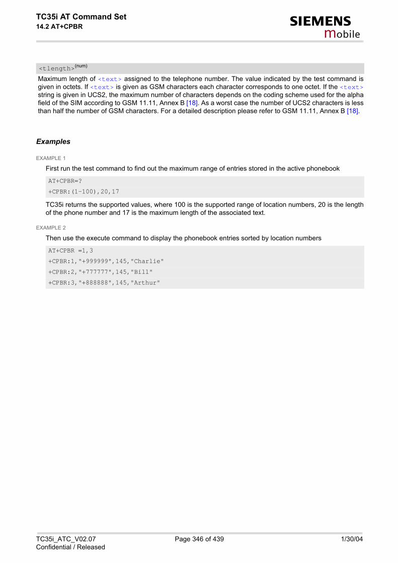
TC35i AT Command Set14.2 AT+CPBR s
mobile
Maximum length of <text> assigned to the telephone number. The value indicated by the test command isgiven in octets. If <text> is given as GSM characters each character corresponds to one octet. If the <text>string is given in UCS2, the maximum number of characters depends on the coding scheme used for the alphafield of the SIM according to GSM 11.11, Annex B [18]. As a worst case the number of UCS2 characters is lessthan half the number of GSM characters. For a detailed description please refer to GSM 11.11, Annex B [18].
Examples
EXAMPLE 1
First run the test command to find out the maximum range of entries stored in the active phonebook
TC35i returns the supported values, where 100 is the supported range of location numbers, 20 is the lengthof the phone number and 17 is the maximum length of the associated text.
EXAMPLE 2
Then use the execute command to display the phonebook entries sorted by location numbers
<tlength>(num)
AT+CPBR=?
+CPBR:(1-100),20,17
AT+CPBR =1,3
+CPBR:1,"+999999",145,"Charlie"
+CPBR:2,"+777777",145,"Bill"
+CPBR:3,"+888888",145,"Arthur"
TC35i_ATC_V02.07 Page 346 of 439 1/30/04Confidential / Released

TC35i AT Command Set14.3 AT+CPBS s
mobile
14.3 AT+CPBS Select phonebook memory storage
This command is used to select the active phonebook storage, i.e. the phonebook storage that all subsequentphonebook commands will be operating on.The read command can be used only after the phonebook data from the SIM have been read successfully forthe first time. Reading starts after successful SIM authentication has been performed, and may take up to 30seconds depending on the SIM used. While the read process is in progress, an attempt to use any of the phone-book commands will result in "+CME Error: 14" (SIM busy).
Syntax
Command Description
The test command returns supported <storage>s as compound value.
The read command returns the currently selected <storage>, the number of <used> entries and the <total>number of entries available for this storage.
Test Command
AT+CPBS=?
Response(s)
+CPBS: (list of supported <storage>s) OK+CME ERROR
Read Command
AT+CPBS?
Response(s)
+CPBS: <storage>, <used>, <total> OK+CME ERROR
Write Command
AT+CPBS=<storage>
Response(s)
OK+CME ERROR:
PIN ASC0 MUX1 MUX2 MUX3
� � � � �
Reference(s)
GSM07.07
TC35i_ATC_V02.07 Page 347 of 439 1/30/04Confidential / Released

TC35i AT Command Set14.3 AT+CPBS s
mobile
The write command selects the phonebook memory <storage>, which is used by other phonebook commands.
Parameter Description
For phonebooks "MC", "RC" and "LD", automatic deletion of the entries stored in ME will be performed if the SIMcard is changed. If the same SIM is removed and reinserted, no automatic deletion is performed. Calls madeafter last switchon will be lost from "MC", "RC" and "LD" phonebook, if the SIM is removed and reinserted duringnormal operation.
“FD“ Fixed dialling phonebookcapacity: depending on SIM cardlocation: SIM
“SM“(&F) SIM phonebookcapacity: depending on SIM cardlocation: SIM
“ON“ MSISDN listcapacity: depending on SIM cardlocation: SIM
“ME“ Mobile Equipment Phonebookcapacity: max. 250 entrieslocation: ME
“LD“ last number dialled phonebook. Stores all voice call numbers dialed with ATD,but no data call numbers.capacity: max. 10 entrieslocation: depending on SIM this phonebook may reside partly or completely inMEAT command +CPBW is not applicable to this storage. The LD list can bedeleted with AT^SDLD or with AT^SPBD.
“MC“ missed (unanswered received) calls listcapacity: max. 10 entrieslocation: ME+CPBW is not applicable to this storage. The MC list can be deleted withAT^SPBD.
“RC“ received calls listcapacity: max. 10 entrieslocation: ME+CPBW is not applicable to this storage. The RC list can be deleted withAT^SPBD.
value indicating the number of used locations in selected memory storage.
value indicating the maximum number of locations allowed in the selected memory storage.
Note
• We recommend to take advantage of the "^SSIM READY" URC. If enabled with AT^SSET, this URC acknowl-edges to the user that SIM data is accessible after SIM PIN authentication. It will be delivered once the MEhas completed reading data from the SIM card.
<storage>(str)
<used>(num)
<total>(num)
TC35i_ATC_V02.07 Page 348 of 439 1/30/04Confidential / Released

TC35i AT Command Set14.4 AT+CPBW s
mobile
14.4 AT+CPBW Write into Phonebook
This command serves to write onto an entry of the phonebook selected with AT+CPBS. It can be used only afterthe phonebook's data has been read successfully from the SIM. Reading starts after successful SIM authentica-tion has been performed and may take up to 30 seconds depending on the SIM used. While the read process isin progress, an attempt to use any of the phonebook commands will result in "+CME Error: SIM busy". To deter-mine when the initial phonebook reading has been finished the URC "^SSIM READY" shall be used, referAT^SSET.
Syntax
Command Description
The test command returns the location range supported by the current storage, the maximum length of <num-ber> field, the range of supported <type> values and the maximum length of <text> field. Note: The lengthmay not be available while SIM storage is selected. If storage does not offer format information, the format listcontains empty parenthesizes.
The write command fills a phonebook entry at memory location <location> of the active storage selected withAT+CPBS.If <storage>="FD" (SIM fixed dialling numbers) is selected, PIN2 authentication has to be performed prior toany write access.If no <location> is given, the first free entry will be used.If <location> is given as the only parameter, the phonebook entry specified by <location> is deleted.If write attempt fails "+CME ERROR" is indicated.
Test Command
AT+CPBW=?
Response(s)
+CPBW: (1-<maxloc>), <nlength>, list of supported <type>s, <tlength> OKERROR+CME ERROR
Write Command
AT+CPBW=[<location>][, <number>[[, <type>][, <text>]]]
Response(s)
OKERROR+CME ERROR
PIN ASC0 MUX1 MUX2 MUX3
� � � � �
Reference(s)
GSM 07.07
TC35i_ATC_V02.07 Page 349 of 439 1/30/04Confidential / Released

TC35i AT Command Set14.4 AT+CPBW s
mobile
Parameter Description
Location number within phonebook memory. The supported range is given whith the test command response.
Phone number with format specified by <type>. Parameter must be present, although it may be an emptystring. However, alphabetic characters are not permitted. <number> may contain printable non-alphabetic characters of the standard GSM alphabet as dialstring modifi-ers, including "*", "#" or "+". However, if <number> contains modifiers other than "*", "#" or "+" the following con-straints shall be considered: • If no <type> was specified explicitly, all accepted modifiers from the GSM alphabet will be saved in the num-
ber string. <type> will be set to 209 (ASCII). However, limitations as listed below for <type> 209 apply. • A <number> saved with <type>=209 requires double memory. In order to fit into a standard location, the
number needs to be reduced to a maximum length of <nlength>/2, including all digits and dial string modi-fiers. Extended locations may be used as stated below for <nlength>.
Type of address octetIf <type> is specified as 129 or 145, any non-digit characters other than "*", "#", or "+" will be removed from thenumber string. If the number string contains such characters, they can be saved with the number string by using<type> 209, see below.
145 dialling string <number> includes international access code character '+'
209 dialling string <number> contains printable non-alphabetic non-digit charac-ters that should be saved with the number string. Remarks as under parameter<number> apply. For phonebook entries with this type, dialling from phone-book with ATD><mem><n> is not possible.
129 otherwise
Text assigned to the phone number. The maximum length for this parameter is given in test command response<tlength>. When using an ASCII terminal, characters which are coded differently in ASCII and GSM have tobe entered via escape sequences as described in chapter Supported character sets.
Max. location for the currently selected storage. For phonebooks located on SIM, this value may vary betweenSIM cards. See AT+CPBS for typical values.
Max. length of phone number for "normal" locations. - Depending on the storage, a limited number of locationswith extended memory is available per phonebook. These locations allow storing numbers with twice the stan-dard length, which is 2*<nlength> digits for normal numbers, but only <nlength> digits for numbers savedwith parameter <type>= 209. If all extended locations of the selected phonebook are used up, then any attemptto write a number which requires extended memory will be denied with CME ERROR 260: INVALID DIALSTRING.
<location>(num)
<number>(str)
<type>(num)
<text>(str)(+CSCS)
<maxloc>(num)
<nlength>(num)
TC35i_ATC_V02.07 Page 350 of 439 1/30/04Confidential / Released

TC35i AT Command Set14.4 AT+CPBW s
mobile
Maximum length of <text> assigned to the telephone number. The value indicated by the test command isgiven in octets. If the <text> string is given in GSM characters, each character corresponds to one octet. If the<text> string is given in UCS2, the maximum number of characters depends on the coding scheme used forthe alpha field of the SIM according to GSM 11.11, Annex B [18]. As a worst case the number of UCS2 charac-ters is less than half the number of GSM characters. For a detailed description please refer to GSM 11.11, AnnexB [18].
Examples
EXAMPLE 1
Make a new phonebook entry at the first free location
EXAMPLE 2
Delete entry at location 1
EXAMPLE 3
The following examples are provided to illustrate the effect of writing phonebook entries with different typesof dial string modifiers in <number>
EXAMPLE 4
Read phonebook entries from locations 5 - 9 via AT+CPBR
<tlength>(num)
AT+CPBW=,"+431234567",145,"international"
AT+CPBW=1
AT+CPBW=5,"12345678",,"Arthur"
AT+CPBW=6,"432!+-765()&54*654#",,"John"
AT+CPBW=7,"432!+-765()&54*654#",129,"Eve"
AT+CPBW=8,"432!+-765()&54*654#",145,"Tom"
AT+CPBW=9,"432!+-765()&54*654#",209,"Richard"
+CPBR:5,"12345678",129,"Arthur"
+CPBR:6,"432!+-765()&54*654#",209,"John"
+CPBR:7,"432+76554*654#",129,"Eve"
+CPBR:8,"+432+76554*654#",145,"Tom"
+CPBR:9,"432!+-765()&54*654#",209,"Richard"
TC35i_ATC_V02.07 Page 351 of 439 1/30/04Confidential / Released

TC35i AT Command Set14.5 AT^SPBC s
mobile
14.5 AT^SPBC Search the first entry in the sorted telephone book
This command can be used to retrieve the index of the first entry starting with selected character <schar> in thesorted list of phonebook records of the phonebook currently selected with AT+CPBS.The sorted list of phonebook records can be accessed with AT command AT^SPBG. The sort order is describedin Chapter 14.1, page 343CAUTION: Please note that the sorted entries are assigned an index of their own which is not identical with thelocation numbers used in the various phonebooks.Therefore, the index retrieved with command AT^SPBC command can be used only as an index for AT^SPBG.Do not use the listed index numbers to dial out or modify entries.This command can be used only after the phonebook data from the SIM have been read successfully for the firsttime. Reading starts after successful SIM authentication has been performed, and may take up to 30 secondsdepending on the SIM used. While the read process is in progress, an attempt to use any of the phonebook com-mands will result in "+CME Error: 14" (SIM busy).
Syntax
Command Description
The test command returns the list of phonebooks for which AT^SPBC is supported, in the syntax used for phone-book selection in AT command AT+CPBS).
The write command retrieves the first (lowest) index in the list of sorted phonebook entries beginning with char-acter <schar>.Since they are not related to the actual locations of the phonebook entries (obtainable with AT+CPBR), Indices
Test Command
AT^SPBC=?
Response(s)
^SPBC: "FD","SM","ME"OKERROR+CME ERROR
Write Command
AT^SPBC=<schar>
Response(s)
^spbc: <index> OKERROR+CME ERROR
PIN ASC0 MUX1 MUX2 MUX3
� � � � �
Reference(s)
SIEMENS
TC35i_ATC_V02.07 Page 352 of 439 1/30/04Confidential / Released

TC35i AT Command Set14.5 AT^SPBC s
mobile
displayed in the write command response may not be used for dialling from phonebook with "ATD><mem><n>"!
Parameter Description
The character to be searched in the sorted list of phonebook entries. Character coding and formatting accordingto the settings made with AT+CSCSsearch algorithms follow the sorting algorithms referenced in Chapter 14.1, page 343.
The first (lowest) index number within the phonebook memory selected with AT+CPBS for which the correspond-ing <text> parameter starts with character <schar>.If no matching phonebook entry is found, <index> =0 will be returned.The index retrieved with command AT^SPBC command can be used only as an index for AT^SPBG. Do not usethe listed index numbers to dial out or modify entries.
Note
• We recommend to take advantage of the "^SSIM READY" URC. If enabled with AT^SSET, this URC acknowl-edges to the user that SIM data is accessible after SIM PIN authentication. It will be delivered once the MEhas completed reading data from the SIM card.
<schar>(str)(+CSCS)
<index>(num)
TC35i_ATC_V02.07 Page 353 of 439 1/30/04Confidential / Released
TC35i AT Command Set14.6 AT^SPBD s
mobile
14.6 AT^SPBD Purge phonebook memory storage
This command is used to purge the selected phonebook <storage> manually, i.e. all entries previously storedin the selected phonebook storage will be deleted.CAUTION! The operation cannot be stopped nor reversed!Automatic purging of phonebooks is performed when the SIM card is removed and replaced by a different SIMcard. This affects the ME-based part of the "LD" storage, and storages "MC" and "RC". Storage "ME" is notaffected.This command can be used only after the phonebook data from the SIM have been read successfully for the firsttime. Reading starts after successful SIM authentication has been performed, and may take up to 30 secondsdepending on the SIM used. While the read process is in progress, an attempt to use any of the phonebook com-mands will result in "+CME Error: 14" (SIM busy).
Syntax
Command Description
The test command returns a list of supported <storage>s.
The write command is used to select the phonebook <storage> to purge.
Test Command
AT^SPBD=?
Response(s)
^SPBD: list of supported <storage>s OK+CME ERROR
Write Command
AT^SPBD=<storage>
Response(s)
OK+CME ERROR
PIN ASC0 MUX1 MUX2 MUX3
� � � � �
Reference(s)
SIEMENS
TC35i_ATC_V02.07 Page 354 of 439 1/30/04Confidential / Released

TC35i AT Command Set14.6 AT^SPBD s
mobile
Parameter Description
This Parameter show all available phonebooks for this command.For detailed description of storages see AT+CPBS.
“FD“ Fixed dialling phonebook (In order to delete this phonebook, PIN2 authentica-tion must be performed first.)
“SM“(&F) SIM phonebook
“ON“ MSISDN list
“ME“ Mobile Equipment Phonebook
“LD“ last number dialled phonebook
“MC“ missed (unanswered received) calls list
“RC“ received calls list
Note
• We recommend to take advantage of the "^SSIM READY" URC. If enabled with AT^SSET, this URC acknowl-edges to the user that SIM data is accessible after SIM PIN authentication. It will be delivered once the MEhas completed reading data from the SIM card.
<storage>(str)
TC35i_ATC_V02.07 Page 355 of 439 1/30/04Confidential / Released

TC35i AT Command Set14.7 AT^SPBG s
mobile
14.7 AT^SPBG Read current Phonebook entries
This command can be used to display the phonebook records of the phonebook currently selected with AT+CPBSin sorted order by name. The sort order is described in Chapter 14.1, page 343"Sort order for Phonebooks"CAUTION: Please note that the sorted entries are assigned an index of their own which is not identical with thelocation numbers used in the various phonebooks.Therefore, the AT^SPBG command can be used for reading only. For example, it helps you find entries startingwith matching characters. However, do not use the listed index numbers to dial out or modify entries.This command can be used only after the phonebook data from the SIM have been read successfully for the firsttime. Reading starts after successful SIM authentication has been performed, and may take up to 30 secondsdepending on the SIM used. While the read process is in progress, an attempt to use any of the phonebook com-mands will result in "+CME Error: 14" (SIM busy).
Syntax
Command Description
The test command returns the index range for this command, the maximum length of <number> field, and themaximum length of <text> field.Note: The length may not be available while SIM storage is selected. If storage does not offer format information,the format list should be empty parenthesises.
The write command selects the index of the phonebook entry, that is to be displayed, in the sorted list of phone-book, or the range of indices to display.
Test Command
AT^SPBG=?
Response(s)
^SPBG: (1-<used>), <nlength>, <tlength> OKERROR+CME ERROR
Write Command
AT^SPBG=<index1>[, <index2>]
Response(s)
[^SPBG: <index1>, <number>, <type>, <text> ][^SPBG: <index2>, <number>, <type>, <text> ]OKERROR+CME ERROR
PIN ASC0 MUX1 MUX2 MUX3
� � � � �
Reference(s)
SIEMENS
TC35i_ATC_V02.07 Page 356 of 439 1/30/04Confidential / Released

TC35i AT Command Set14.7 AT^SPBG s
mobile
If no <index2> is given, only the entry at <index1> will be displayed.
Parameter Description
The first index number within the sorted list of phonebook for which the corresponding entry is to be displayed.The supported range is given in the test command response.If <index 1> exceeds the upper bound <used>, the AT command will return a CME ERROR 21.
The last index number within the sorted list of phonebook for which the corresponding entry is to be displayed.The supported range is given in the test command response.If both <index1> and <index2> are in the range indicated by the test command in parameter <used>, the listof entries will be output and terminated with OK.If <index2> exceeds the range indicated by the test command in parameter <used>, the list of entries will beoutput but terminated with a +CME ERROR 21 "INVALID INDEX".
String type phone number in format specified by <type>.The number parameter may be an empty string.
type of address octet
145 dialling string <number> includes international access code character '+'
209 dialling string <number> contains printable non-alphabetic non-digit charac-ters saved with the number string.For further detail, check the parameter descriptions for at command AT+CPBW.
129 otherwise
Text assigned to the phone number. The maximum length for this parameter is given in test command response<tlength>.
value indicating the number of used locations in selected memory storage.
Max. length of phone number for "normal" locations. - Depending on the storage, a limited number of locationswith extended memory is available per phonebook. Please refer to AT command AT+CPBW for detail.
Max. length of <text> assigned to the telephone number. The value indicated by the test command is given inoctets. If the <text> string is given in GSM characters, each character corresponds to one octet. If the <text>string is given in UCS2, the maximum number of characters depends on the coding scheme used for the alphafield of the SIM according to GSM 11.11, Annex B. In the worst case, the number of UCS2 characters is lessthan half the number of GSM characters. For a detailed description see GSM 11.11, Annex B.
<index1>(num)
<index2>(num)
<number>(str)
<type>(num)
<text>(str)(+CSCS)
<used>(num)
<nlength>(num)
<tlength>(num)
TC35i_ATC_V02.07 Page 357 of 439 1/30/04Confidential / Released

TC35i AT Command Set14.7 AT^SPBG s
mobile
Notes
• The AT^SPBG feature is able to sort by the first 6 matching characters only. All following characters will beignored.
• The command can be used for the phone books "SM", "FD", "ME" (cf. AT+CPBS).
• We recommend to take advantage of the "^SSIM READY" URC. If enabled with AT^SSET, this URC acknowl-edges to the user that SIM data is accessible after SIM PIN authentication. It will be delivered once the MEhas completed reading data from the SIM card.
Examples
EXAMPLE 1
Using AT^SPBG to obtain a sorted list of phonebook entries. - First, run the test command to find out the range of phonebook entries stored in the active phonebook:
TA returns the number of entries in the format:
where 33 is the number of used entries in the active phonebook storage. - Now, run the write command to display the phonebook entries by alphabetical order. It is recommended
to enter the full range to obtain best results.
TA returns phonebook entries by alphabetical order:
AT^SPBG=?
^SPBG: (1-33),20,17
AT^SPBG=1,33
^SPBG:1,"+999999",145,"Arthur" ^SPBG:2,"+777777",145,"Bill" ^SPBG:3,"+888888",145,"Charlie" .........
TC35i_ATC_V02.07 Page 358 of 439 1/30/04Confidential / Released

TC35i AT Command Set14.8 AT^SPBS s
mobile
14.8 AT^SPBS Step through the selected phonebook alphabetically
This command can be used to scroll sequentially through the active phonebook records in alphabetical order byname. Three entries will be displayed at a time.This command can be used only after the phonebook data from the SIM have been read successfully for the firsttime. Reading starts after successful SIM authentication has been performed, and may take up to 30 secondsdepending on the SIM used. While the read process is in progress, an attempt to use any of the phonebook com-mands will result in "+CME Error: 14" (SIM busy).This command can be used for the ME, SM and FD phonebook.
Syntax
Command Description
Test command returns a list of supported <value>.
Every time the write command is executed, 3 rows of phone book records are returned. Each triplet overlaps withthe next one. The actual index depends on parameter <value>. This parameter determines whether the indexwill be increased or decreased.If the index in one output line reaches the last index in the alphabetical list, the next output line will display thefirst list entry.After the last record of the phonebook has been reached (see parameter <used> for AT^SPBG), the <inter-nal-counter> switches over to the first.See examples below.
Test Command
AT^SPBS=?
Response(s)
^SPBS: (list of supported <value>) OK
Write Command
AT^SPBS=<value>
Response(s)
^SPBS: <index-a>, <number>, <type>, <text> ^SPBS: <index-b>, <number>, <type>, <text> ^SPBS: <index-c>, <number>, <type>, <text> OK+CME ERROR
PIN ASC0 MUX1 MUX2 MUX3
� � � � �
Reference(s)
SIEMENS
TC35i_ATC_V02.07 Page 359 of 439 1/30/04Confidential / Released

TC35i AT Command Set14.8 AT^SPBS s
mobile
Parameter Description
1 To make a step forward in the alphabetically sorted phonebook.
2 To make a step backward in the alphabetically sorted phonebook.
1...maxindex The index in the sorted list of phonebook entries that identifies the first entry inalphabetical order of names displayed.The value of <index-a> is determined by the value of the internal counter andby parameter <value>.After a write command has terminated successfully with "OK", the value fromparameter <index-a> is saved and retained as the new internal countervalue.Mind after the last record of phonebook, the first entry follows.
1...maxindex The index in the sorted list of phonebook entries that identifies the second entryin alphabetical order of names displayed.Mind after the last record of phonebook, the first entry follows.
1...maxindex The index in the sorted list of phonebook entries that identifies the third entryin alphabetical order of names displayed.Mind after the last record of phonebook, the first entry follows.
string type phone number in format specified by <type>.the number parameter may be an empty string.
type of address octet
145 dialling string <number> includes international access code character '+'
209 dialling string <number> contains printable non-alphabetic non-digit charac-ters saved with the number string.For phonebook entries with this <type>, dialling from phonebook withATD><mem><n> is not possible. For further detail, check the parameterdescriptions for at command AT+CPBW.
129 otherwise
Text assigned to the phone number.
0(&F)...maxindex This Parameter is only an internal parameter and cannot modified directly.The internal counter will be reset to index 0 after a call to ATZ or AT&F.
<value>(num)
<index-a>(num)
<index-b>(num)
<index-c>(num)
<number>(str)
<type>(num)
<text>(str)(+CSCS)
<internal-counter>(num)
TC35i_ATC_V02.07 Page 360 of 439 1/30/04Confidential / Released
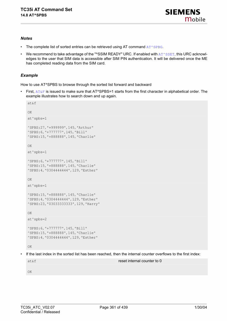
TC35i AT Command Set14.8 AT^SPBS s
mobile
Notes
• The complete list of sorted entries can be retrieved using AT command AT^SPBG.
• We recommend to take advantage of the "^SSIM READY" URC. If enabled with AT^SSET, this URC acknowl-edges to the user that SIM data is accessible after SIM PIN authentication. It will be delivered once the MEhas completed reading data from the SIM card.
Example
How to use AT^SPBS to browse through the sorted list forward and backward
• First, AT&F is issued to make sure that AT^SPBS=1 starts from the first character in alphabetical order. Theexample illustrates how to search down and up again.
• If the last index in the sorted list has been reached, then the internal counter overflows to the first index:
at&f
OK
at^spbs=1
^SPBS:27,"+999999",145,"Arthur"^SPBS:6,"+777777",145,"Bill"^SPBS:15,"+888888",145,"Charlie"
OK
at^spbs=1
^SPBS:6,"+777777",145,"Bill"^SPBS:15,"+888888",145,"Charlie"^SPBS:4,"0304444444",129,"Esther"
OK
at^spbs=1
^SPBS:15,"+888888",145,"Charlie"^SPBS:4,"0304444444",129,"Esther"^SPBS:23,"03033333333",129,"Harry"
OK
at^spbs=2
^SPBS:6,"+777777",145,"Bill"^SPBS:15,"+888888",145,"Charlie"^SPBS:4,"0304444444",129,"Esther"
OK
at&f reset internal counter to 0
OK
TC35i_ATC_V02.07 Page 361 of 439 1/30/04Confidential / Released

TC35i AT Command Set14.8 AT^SPBS s
mobile
at^spbs=2 step down 1 entry starting from (internal counter)=0 - overflow occurs.
^SPBS:9,"+49301234567",145,"TomTailor"^SPBS:27,"+999999",145,"Arthur"^SPBS:6,"+777777",145,"Bill"
OK
TC35i_ATC_V02.07 Page 362 of 439 1/30/04Confidential / Released

TC35i AT Command Set14.9 AT^SDLD s
mobile
14.9 AT^SDLD Delete the 'last number redial' memory
Reading starts after successful SIM authentication has been performed, and may take up to 30 seconds depend-ing on the SIM used. While the read process is in progress, an attempt to use any of the phonebook commandswill result in "+CME Error: 14" (SIM busy).
Syntax
Command Description
The execute command deletes all numbers stored in the LD memory.
Test Command
AT^SDLD=?
Response(s)
OK
Exec Command
AT^SDLD
Response(s)
OKERROR+CME ERROR: <err>
PIN ASC0 MUX1 MUX2 MUX3
� � � � �
Reference(s)
SIEMENS
TC35i_ATC_V02.07 Page 363 of 439 1/30/04Confidential / Released

TC35i AT Command Set15. Audio Commands s
mobile
15. Audio Commands
The AT Commands described in this chapter are related to the TC35i's audio interface.
15.1 Audio programming model
The following figure illustrates how the signal path can be adjusted with the parameters <inCalibrate>,<inBbcGain>, <outBbcGain>, <outCalibrate> and <sideTone>.
Figure 15.1: Audio programming model
TC35i_ATC_V02.07 Page 364 of 439 1/30/04Confidential / Released

TC35i AT Command Set15.2 ATL s
mobile
15.2 ATL Set monitor speaker loudness
Syntax
Parameter Description
Notes
• Commands ATL and ATM are implemented only for V.25ter compatibility reasons and have no effect.
• In multiplex mode the command is supported on logical channel 1 only.
Exec Command
ATL[<val>]
Response(s)
OK
PIN ASC0 MUX1 MUX2 MUX3
� � � � �
Reference(s)
V.25ter
<val>(num)
TC35i_ATC_V02.07 Page 365 of 439 1/30/04Confidential / Released

TC35i AT Command Set15.3 ATM s
mobile
15.3 ATM Set monitor speaker mode
Syntax
Parameter Description
Notes
• Commands ATL and ATM are implemented only for V.25ter compatibility reasons and have no effect.
• In multiplex mode the command is supported on logical channel 1 only.
Exec Command
ATM[<val>]
Response(s)
OK
PIN ASC0 MUX1 MUX2 MUX3
� � � � �
Reference(s)
V.25ter
<val>(num)
TC35i_ATC_V02.07 Page 366 of 439 1/30/04Confidential / Released

TC35i AT Command Set15.4 AT+CLVL s
mobile
15.4 AT+CLVL Loudspeaker volume level
Syntax
Parameter Description
Loudspeaker Volume Level
0...4(D)
Notes
• The write command can only be used in audio mode 2 - 6.
• The values of the volume steps are specified with the parameters <outCalibrate>[0],...<outCali-brate>[4] of the AT^SNFO command.
Test Command
AT+CLVL=?
Response(s)
+CLVL: (list of supported<level>s) OK
Read Command
AT+CLVL?
Response(s)
+CLVL: <level> OKERROR+CME ERROR: <err>
Write Command
AT+CLVL=<level>
Response(s)
OKERROR+CME ERROR: <err>
PIN ASC0 MUX1 MUX2 MUX3
� � � � �
Reference(s)
GSM 07.07
<level>(num)
TC35i_ATC_V02.07 Page 367 of 439 1/30/04Confidential / Released

TC35i AT Command Set15.4 AT+CLVL s
mobile
• As an alternative to AT+CLVL, you can use AT^SNFO and AT^SNFV. The parameter <level> is identical with<outStep> used by both commands.
• Any change to <level> (or <outStep>) takes effect in audio modes 2 to 6. That is, when you change<level> (or <outStep>) and then select another mode with AT^SNFS, the same step will be applied.The only exception is audio mode 1 which is fixed to <level>=4 (or accordingly <outStep>=4).
• <level> (or <outStep>) is stored non-volatile when the ME is powered down with AT^SMSO or reset withAT+CFUN=1,1.
TC35i_ATC_V02.07 Page 368 of 439 1/30/04Confidential / Released

TC35i AT Command Set15.5 AT+CMUT s
mobile
15.5 AT+CMUT Mute control
Syntax
Command Description
This command can be used in all audio modes (1 to 6) and during a voice call only. See AT^SNFS for more detailson the various audio modes. As alternative, you can use the AT^SNFM command. During an active call, usersshould be aware that when they switch back and forth between different audio modes (for example handsfreeon/off) the value of <mute> does not change, i.e. the microphone mode is retained until explicitly changed.
Parameter Description
0(P) mute off
1 mute on
Test Command
AT+CMUT=?
Response(s)
+CMUT: (list of supported<mute>s) OK
Read Command
AT+CMUT?
Response(s)
+CMUT: <mute> OKERROR+CME ERROR: <err>
Write Command
AT+CMUT=<mute>
Response(s)
OKERROR+CME ERROR: <err>
PIN ASC0 MUX1 MUX2 MUX3
� � � � �
Reference(s)
GSM 07.07
<mute>(num)
TC35i_ATC_V02.07 Page 369 of 439 1/30/04Confidential / Released

TC35i AT Command Set15.6 AT+VTD s
mobile
15.6 AT+VTD Tone duration
Syntax
Command Description
This command refers to an integer <duration> that defines the length of tones transmitted with the AT+VTScommand.
Parameter Description
duration of the tone in 1/10 second
1(&F)...255
Test Command
AT+VTD=?
Response(s)
+VTD: (list of supported<duration>s) OK
Read Command
AT+VTD?
Response(s)
<duration> OK
Write Command
AT+VTD=<duration>
Response(s)
OK
PIN ASC0 MUX1 MUX2 MUX3
� � � � �
Reference(s)
GSM 07.07
<duration>(num)
TC35i_ATC_V02.07 Page 370 of 439 1/30/04Confidential / Released

TC35i AT Command Set15.7 AT+VTS s
mobile
15.7 AT+VTS DTMF and tone generation
The Write command is intended to send ASCII characters or strings which cause the Mobile Switching Center(MSC) to transmit DTMF tones to a remote subscriber. It works during active voice calls only and offers the fol-lowing variants: • AT+VTS=<dtmfString> allows to send a sequence of DTMF tones with a duration defined with AT+VTD. • AT+VTS=<dtmf>[,<duration>] allows to send a single DTMF tone. In this case, the duration can be ind-
vidually determined during the call.
Syntax
Parameter Description
String of ASCII characters in the set 0-9,#,*,A, B, C, D. Maximal length of the string is 29. The string must beenclosed in quotation marks ("...").
ASCII character in the set 0...9,#,*, A, B, C, D.
Test Command
AT+VTS=?
Response(s)
+VTS: (list of supported<dtmf>s), (list of supported<duration>s) OK
Write Command
AT+VTS=<dtmfString>
Response(s)
OK
Write Command
AT+VTS=<dtmf>[, <duration>]
Response(s)
OK
PIN ASC0 MUX1 MUX2 MUX3
� � � � �
Reference(s)
GSM 07.07
<dtmfString>(str)
<dtmf>(str)
TC35i_ATC_V02.07 Page 371 of 439 1/30/04Confidential / Released

TC35i AT Command Set15.7 AT+VTS s
mobile
Tone duration in 1/10 second. If not specified current setting of AT+VTD is used.
1...255
<duration>(num)
TC35i_ATC_V02.07 Page 372 of 439 1/30/04Confidential / Released

TC35i AT Command Set15.8 AT^SAIC s
mobile
15.8 AT^SAIC Audio Interface Configuration
Syntax
Command Description
This command configures the interface connections of the active audio mode.
Parameter Description
Input and output selection
1 Not supported
2 Analog input and output
Test Command
AT^SAIC=?
Response(s)
^SAIC:(list of supported <io>s), (list of supported<mic>s), (list of supported<ep>s) OK
Read Command
AT^SAIC?
Response(s)
^SAIC: <io>, <mic>, <ep>OK
Write Command
AT^SAIC=<io>[, <mic>[, <ep>]]
Response(s)
OKERROR+CME ERROR: operation not allowed
PIN ASC0 MUX1 MUX2 MUX3
� � � � �
Reference(s)
SIEMENS
<io>(num)(^SNFW)
TC35i_ATC_V02.07 Page 373 of 439 1/30/04Confidential / Released

TC35i AT Command Set15.8 AT^SAIC s
mobile
Microphone selection
1 Microphone 1
2 Microphone 2
Select differential earpiece amplifier
1 Selects the earpiece amplifier 1
2 Selects the earpiece amplifier 2
3 Selects both amplifiers. Note that both amplifiers are connected in parallel andtherefore, get the same output power if <ep>=3.
Notes
• The AT^SAIC Write command is usable only in audio modes 2 - 6. If AT^SNFS=1, any attempt to use theAT^SAIC Write command returns "+CME ERROR: operation not allowed". This is because all default param-eters in audio mode 1 are determined for type approval and are not adjustable.
• To allocate a specific audio mode to one of the audio interfaces, first select the audio mode with AT^SNFSand then choose the interface using AT^SAIC.
• The factory defaults of AT^SAIC vary with the selected audio mode.If AT^SNFS=1 or 4 or 5, then AT^SAIC=2,1,1. If AT^SNFS=2 or 3 or 6, then AT^SAIC=2,2,2. (Although given by default, this setting applies to the TC35imodule only, it cannot be used with the TC35i Terminal where the second audio interface is not connected.Nevertheless, you can configure TC35i Terminal for operation with audio modes 2, 3 or 6 by settingAT^SAIC=2,1,1 instead. See examples provided with AT^SNFS.) AT^SNFD can be used to reset the factory defaults.
• For use after restart of the ME, you are advised to store the settings of AT^SAIC and AT^SNFS to the audioprofile set with AT^SNFW. Otherwise, audio mode 1 (AT^SNFS=1) and audio interface 2 (AT^SAIC=2,1,1) willbe active each time the ME is powered up.
<mic>(num)(^SNFW)
<ep>(num)(^SNFW)
TC35i_ATC_V02.07 Page 374 of 439 1/30/04Confidential / Released

TC35i AT Command Set15.9 AT^SNFA s
mobile
15.9 AT^SNFA Set or query of microphone attenuation
Syntax
Command Description
The test command returns the supported values of the parameter <atten>.
The read command returns the current attenuation value on the microphone path for the current audio device(selected by AT^SNFS).
Write command controls the large-scale attenuation on the microphone path for the current audio device(selected by AT^SNFS) with the following restrictions: • It is not allowed for audio device 1• As long as the microphone is muted, the write command is temporarily disabled• Setting of value 0 is not allowed (use AT^SNFM=0 for this).• For values greater than 32767, 32767 will be used.
Test Command
AT^SNFA=?
Response(s)
^SNFA: (list of supported <atten>s) OK
Read Command
AT^SNFA?
Response(s)
^SNFA: <atten> OK
Write Command
AT^SNFA=<atten>
Response(s)
OKERRORCME ERROR: <err>
PIN ASC0 MUX1 MUX2 MUX3
� � � � �
Reference(s)
SIEMENS
TC35i_ATC_V02.07 Page 375 of 439 1/30/04Confidential / Released

TC35i AT Command Set15.9 AT^SNFA s
mobile
Parameter Description
Multiplication factor for input samples. Parameter <atten> is identical with <inCalibrate> of AT^SNFI.Formula used to calculate microphone attenuation (negative gain):Gain in dB = 20 * log(<atten>/32768)
0...32767(P)...65535
0 Microphone is muted
32767 No attenuation on the microphone path
Notes
• The command is provided for compatibility with M20 and is a subset of AT^SNFI. The parameter <inCali-brate> of AT^SNFI is identical with <atten> of AT^SNFA.
• To make the changes persistent use AT^SNFW.
Example
<atten>(num)(^SNFW)
^SYSSTART
at^snfa=?
^SNFA: (0-65535)
OK
at^snfa?
^SNFA: 32767
OK
at^snfs=4
OK
at^snfa=1
OK
at^snfa?
^SNFA: 1
OK
at^snfi?
^SNFI: 5,1
OK
at^snfi=5,45
OK
at^snfa?
^SNFA: 45
OK
TC35i_ATC_V02.07 Page 376 of 439 1/30/04Confidential / Released
TC35i AT Command Set15.10 AT^SNFD s
mobile
15.10 AT^SNFD Set audio parameters to manufacturer default values
Syntax
Command Description
TA sets the active audio parameters to manufacturer defined default values.
Notes
• The restored values are:AT^SNFI: <inBbcGain>, <inCalibrate> (or the equivalent AT^SNFA parameters)AT^SNFO: <outBbcGain>, <outCalibrate>[0 to 4], <sideTone>AT^SAIC: <io>, <mic>, <ep>AT^SNFS: <audMode>
• Remember that the factory set audio mode 1 is fixed to <outStep>=4. Consequently, AT^SNFD restores<audMode> together with <outStep>=4, but does not affect the values of <outStep> currently selected inaudio modes 2 - 6. This means, if <audMode>=1, the read commands AT^SNFO, AT^SNFV and AT+CLVL willalways return <outStep>=4. In all other modes the <outStep> value is retained until explicitly changed.
Test Command
AT^SNFD=?
Response(s)
OK
Exec Command
AT^SNFD
Response(s)
OK
PIN ASC0 MUX1 MUX2 MUX3
� � � � �
Reference(s)
SIEMENS
TC35i_ATC_V02.07 Page 377 of 439 1/30/04Confidential / Released

TC35i AT Command Set15.11 AT^SNFI s
mobile
15.11 AT^SNFI Set microphone path parameters
Syntax
Command Description
TA sets microphone path amplifying.
Parameter Description
ADC gain adjustable in eight 6 dB steps from 0 dB to 42 dB (0=0dB, 7=42dB, 8 steps of 6 dB).
0...7
Multiplication factor for input samples. Formula to calculate the negative gain (attenuation) of the input signal:Gain in dB = 20 * log (inCalibrate / 32768)
0...32767
Test Command
AT^SNFI=?
Response(s)
^SNFI: (list of supported <inBbcGain>s) , (list of supported <inCalibrate>s) OK
Read Command
AT^SNFI?
Response(s)
^SNFI: <inBbcGain>, <inCalibrate> OK
Write Command
AT^SNFI=<inBbcGain>, <inCalibrate>
Response(s)
OK
PIN ASC0 MUX1 MUX2 MUX3
� � � � �
Reference(s)
SIEMENS
<inBbcGain>(num)(^SNFW)
<inCalibrate>(num)(^SNFW)
TC35i_ATC_V02.07 Page 378 of 439 1/30/04Confidential / Released

TC35i AT Command Set15.11 AT^SNFI s
mobile
Notes
• Write command works only in audio modes 2 to 6!
• Read and write options of this command refer to the active audio mode.
• The range of <inCalibrate> is up to 65535 but will be suppressed to 32767. Values above <inCali-brate>= 65535 will cause a failure.
• Changed values have to be stored with AT^SNFW.
• Attention! When you adjust audio parameters avoid exceeding the maximum allowed level. Bear in mind thatexposure to excessive levels of noise can cause physical damage to users!
• The default values are customer specific.
TC35i_ATC_V02.07 Page 379 of 439 1/30/04Confidential / Released

TC35i AT Command Set15.12 AT^SNFM s
mobile
15.12 AT^SNFM Mute microphone
Syntax
Command Description
The test command returns the supported values of the parameter <mute>.
The read command returns whether the microphone is on or off during voice calls.
The write command can be used to mute or activate the microphone during voice calls.
Parameter Description
0 Mute microphone
1(P) Microphone on
Notes
• The write command works in all audio modes but only during active voice calls.
Test Command
AT^SNFM=?
Response(s)
^SNFM: (list of supported <mute>s) OK
Read Command
AT^SNFM?
Response(s)
^SNFM: <mute> OK
Write Command
AT^SNFM=<mute>
Response(s)
OK
PIN ASC0 MUX1 MUX2 MUX3
� � � � �
Reference(s)
SIEMENS
<mute>(num)
TC35i_ATC_V02.07 Page 380 of 439 1/30/04Confidential / Released

TC35i AT Command Set15.12 AT^SNFM s
mobile
• This command can be used in all audio modes (1 to 6) and during a voice call only. See AT^SNFS for moredetails on the various audio modes.
• During an active call, users should be aware that when they switch back and forth between different audiomodes (for example handsfree on/off) the value of <mute> does not change, i.e. the microphone mode isretained until explicitly changed.
• As alternative, you can use the AT+CMUT command.
TC35i_ATC_V02.07 Page 381 of 439 1/30/04Confidential / Released

TC35i AT Command Set15.13 AT^SNFO s
mobile
15.13 AT^SNFO Set audio output (= loudspeaker path) parameter
Syntax
Command Description
TA sets earpiece path amplifying.
Parameter Description
Negative DAC gain (attenuation) adjustable in four 6 dB steps from 0 dB to -18 dB (0=0 dB, 3=-18 dB)
0...3
Test Command
AT^SNFO=?
Response(s)
^SNFO: (list of supported <outBbcGain>s) (list of supported <outCalibrate>s) (list of supported <outStep>s) (list of supported <sideTone>s) OK
Read Command
AT^SNFO?
Response(s)
^SNFO: <outBbcGain>, <outCalibrate>[0] , <outCalibrate>[1] , <outCalibrate>[2] , <outCalibrate>[3] , <outCalibrate>[4] , <outStep>, <sideTone> OK
Write Command
AT^SNFO=<outBbcGain>, <outCalibrate>[0] , <outCalibrate>[1] , <outCalibrate>[2] , <outCalibrate>[3] , <outCalibrate>[4] , <outStep>, <sideTone>
Response(s)
OK
PIN ASC0 MUX1 MUX2 MUX3
� � � � �
Reference(s)
SIEMENS
<outBbcGain>(num)(^SNFW)
TC35i_ATC_V02.07 Page 382 of 439 1/30/04Confidential / Released

TC35i AT Command Set15.13 AT^SNFO s
mobile
Formula to calculate the value of the 5 volume steps selectable with parameter <outStep>:Attenuation = 20 log * (2 * outCalibrate[n] / 32768)
0...32767
Volume steps 0 - 4, each defined with outCalibrate[n]
0...[4]
Multiplication factor for the sidetone gain.Formula to calculate how much of the original microphone signal is added to the earpiece signal:Sidetone gain in dB = 20 * log (sideTone / 32768).
0...32767
Notes
• The write command works only in audio modes 2 to 6.
• The read and write commands refer to the active audio mode.
• <outCalibrate> specifies the amount of volume of each <outStep>. The range of each <outCali-brate> is up to 65535, but will be suppressed to 32767. A value above <outCalibrate>= 65535 will causean error.
• The range of <sideTone> is up to 65535, but will be suppressed to 32767. A value above <sideTone>=65535 will cause an error.
• Any change to <outStep> takes effect in audio modes 2 to 6. That is, when you change <outStep> andthen select another mode with AT^SNFS, the same step will be applied. Nevertheless, the sound quality andthe amount of volume are not necessarily the same, since all remaining audio parameters can use differentvalues in either mode.
• Audio mode 1 is fixed to <outStep>=4. In this mode, any attempt to change <outStep> or other parametersreturns an error.
• The value of <outStep> is stored non-volatile when the ME is powered down with AT^SMSO or reset withAT+CFUN=x,1. Any other parameters changed with AT^SNFO need to be saved with AT^SNFW for use afterrestart. See also AT^SNFD for details on restoring factory defaults.
• The values of <outStep> can also be changed with AT^SNFV and AT+CLVL.
• CAUTION! When you adjust audio parameters avoid exceeding the maximum allowed level. Bear in mind thatexposure to excessive levels of noise can cause physical damage to users!
<outCalibrate>(num)(^SNFW)
<outStep>(num)
<sideTone>(num)(^SNFW)
TC35i_ATC_V02.07 Page 383 of 439 1/30/04Confidential / Released

TC35i AT Command Set15.14 AT^SNFPT s
mobile
15.14 AT^SNFPT Set progress tones
Syntax
Command Description
The write command controls the Call Progress Tones generated at the beginning of a mobile originated callsetup.
Parameter Description
0 Disables Call Progress Tones
1(P) Enables Call Progress Tones (audible tones shortly heard on the phone whenME starts to set up a call.)
Note
• Please note that the setting is stored volatile, i.e. after restart or reset, the default value 1 will be restored.
Test Command
AT^SNFPT=?
Response(s)
^SNFPT: (list of supported <pt>s) OK
Read Command
AT^SNFPT?
Response(s)
^SNFPT: <pt> OK
Write Command
AT^SNFPT=<pt>
Response(s)
OK
PIN ASC0 MUX1 MUX2 MUX3
� � � � �
Reference(s)
SIEMENS
<pt>(num)
TC35i_ATC_V02.07 Page 384 of 439 1/30/04Confidential / Released

TC35i AT Command Set15.15 AT^SNFS s
mobile
15.15 AT^SNFS Select audio hardware set
Syntax
Command Description
The write command serves to set the audio mode required for the connected equipment. For use after restart ofthe module, you are advised to store the selected mode to the audio profile set with AT^SNFW. Otherwise, audiomode 1 will be active each time the module is powered up.AT^SNFS can also be used in conjunction with AT^SAIC. This is useful, for example, if both interfaces are oper-ated alternatively to benefit from different devices. Each audio mode can be assigned a specific interface. To doso, first select the audio mode with AT^SNFS, then activate the audio interface with AT^SAIC and finally enterAT^SNFW to store the settings to your audio profile. To switch back and forth it is sufficient to use AT^SNFS.
Test Command
AT^SNFS=?
Response(s)
^SNFS: (list of supported <audMode>s) OK
Read Command
AT^SNFS?
Response(s)
^SNFS: <audMode> OK
Write Command
AT^SNFS=<audMode>
Response(s)
OKERRORCME ERROR: <err>
PIN ASC0 MUX1 MUX2 MUX3
� � � � �
Reference(s)
SIEMENS
TC35i_ATC_V02.07 Page 385 of 439 1/30/04Confidential / Released

TC35i AT Command Set15.15 AT^SNFS s
mobile
Parameter Description
[1] Audio mode 1: Standard mode optimized for the reference handset, that canbe connected to the analog interface 1 (see your "Hardware Interface Descrip-tion" for information on this handset.) To adjust the volume use the knob of thereference handset. In audio mode 4, this handset can be used with userdefined parameters.Note: The default parameters are determined for type approval and are notadjustable with AT commands. AT^SNFD restores <audMode> 1.
2 Audio mode 2: Customer specific mode for a basic handsfree device (SiemensCar Kit Portable).Analog interface 2 is assumed as default.
3 Audio mode 3: Customer specific mode for a mono-headset.Analog interface 2 is assumed as default.
4 Audio mode 4: Customer specific mode for a user handset.Analog interface 1 is assumed as default.
5 Audio mode 5: Customer specific mode. Analog interface 1 is assumed as default.
6 Audio mode 6: Customer specific mode.Analog interface 2 is assumed as default.
Notes
• The write command can be used during a voice call to switch back and forth between different modes. Thisallows the user, for example, to switch handsfree operation on and off.
• Users should be aware that <outStep> is a global setting. This means, when another audio mode is selectedduring a call, the value of <outStep> does not change. This is also true for mute operation which can be setwith AT^SNFM or AT+CMUT: If the microphone is muted and the user selects another audio mode during thecall, then the microphone remains muted until explicitly changed. Exception: In audio mode 1 <outStep>=4is fix.
<audMode>(num)(^SNFW)
TC35i_ATC_V02.07 Page 386 of 439 1/30/04Confidential / Released

TC35i AT Command Set15.15 AT^SNFS s
mobile
Examples
EXAMPLE 1
Suppose a user wishes to use alternatively a handsfree device and a handset. The handset can be connectedto the first analog interface and adjusted to audio mode 4. The handsfree device can be attached to the sec-ond analog interface and adjusted to audio mode 2. The factory defaults of AT^SAIC need not be changed.Settings for the handset:
Settings for the handsfree device:
To store the configuration to the user defined audio profile:
To switch back and forth:
EXAMPLE 2
The following example illustrates a combination of a handset and a handsfree device connected to other inter-faces than those assumed as factory default.Settings for a handset connected to the second analog interface and adjusted to audio mode 4:
AT^SNFS=4
OK
AT^SAIC? Factory default of AT^SAIC assigned to audio mode 4.^SAIC: 2,1,1
OK
AT^SNFS=2
OK
AT^SAIC? Factory default of AT^SAIC assigned to audio mode 2.^SAIC: 2,2,2
OK
AT^SNFW Stores the audio mode and the interface.OK
AT^SNFS=4 Switches to the handset connected to analog interface 1.OK
AT^SNFS=2 Switches to the handsfree device at analog interface 2.OK
AT^SNFS=4
OK
AT^SAIC=2,2,2
OK
TC35i_ATC_V02.07 Page 387 of 439 1/30/04Confidential / Released

TC35i AT Command Set15.15 AT^SNFS s
mobile
Settings for a handsfree device connected to the first analog interface and adjusted to audio mode 2:
To store the configuration to the user defined audio profile:
To switch back and forth:
AT^SNFS=2
OK
AT^SAIC=2,1,1
OK
AT^SNFW Stores the audio mode and the interface.OK
AT^SNFS=4 Switches to the handset connected to analog interface 1.OK
AT^SNFS=2 Switches to the handsfree device at analog interface 2.OK
TC35i_ATC_V02.07 Page 388 of 439 1/30/04Confidential / Released

TC35i AT Command Set15.16 AT^SNFV s
mobile
15.16 AT^SNFV Set loudspeaker volume
Syntax
Command Description
The test command returns the supported values of the parameter <outStep>.
The read command returns the current value of parameter <outStep>.
The write command can be used to set the volume of the loudspeaker to the value <outCalibrate> addressedby <outStep>.
Parameter Description
The actual volume of each step is defined by the parameter <outCalibrate>, which can be set with AT^SNFO.
0...4(P)
Test Command
AT^SNFV=?
Response(s)
^SNFV: (list of supported <outStep>s) OK
Read Command
AT^SNFV?
Response(s)
^SNFV: <outStep> OK
Write Command
AT^SNFV=<outStep>
Response(s)
OKERROR+CME ERROR
PIN ASC0 MUX1 MUX2 MUX3
� � � � �
Reference(s)
SIEMENS
<outStep>(num)
TC35i_ATC_V02.07 Page 389 of 439 1/30/04Confidential / Released

TC35i AT Command Set15.16 AT^SNFV s
mobile
Notes
• The read and write commands refer to the active audio mode.
• The write command works only in audio modes 2 to 6!
• Any change to <outStep> takes effect in audio modes 2 to 6. That is, when you change <outStep> andthen select another mode with AT^SNFS, the same step will be applied. Nevertheless, the actual volume canbe quite different, depending on the values of <outCalibrate> set in each mode. The only exception isaudio mode 1 which is fixed to <outStep>=4.
• <outStep> is stored non-volatile when the ME is powered down with AT^SMSO or reset with AT+CFUN=1,1.<outStep> is not stored by AT^SNFW.
• <outStep> can also be changed by AT^SNFO (Chapter 15.13, page 382) and AT+CLVL (Chapter 15.4, page367).
TC35i_ATC_V02.07 Page 390 of 439 1/30/04Confidential / Released

TC35i AT Command Set15.17 AT^SNFW s
mobile
15.17 AT^SNFW Write audio setting in non-volatile store
Syntax
Command Description
TA writes the active audio parameters in non-volatile store related to the active mode.
Notes
• Execute command works only in audio mode 2 to 6.
• TA writes the following audio parameter values in non-volatile store: AT^SNFI: <inBbcGain>, <inCalibrate> AT^SNFO: <outBbcGain>, <outCalibrate>[0 to 4], <sideTone> AT^SNFS: <audMode> AT^SAIC: <io>, <mic>, <ep>.
Test Command
AT^SNFW=?
Response(s)
OK
Exec Command
AT^SNFW
Response(s)
OKERRORCME ERROR: <err>
PIN ASC0 MUX1 MUX2 MUX3
� � � � �
Reference(s)
SIEMENS
TC35i_ATC_V02.07 Page 391 of 439 1/30/04Confidential / Released

TC35i AT Command Set15.18 AT^SRTC s
mobile
15.18 AT^SRTC Ring tone configuration
Syntax
Command Description
The test command returns the current ring tone and volume
The read command returns the current <type> and current <volume>. The read command can be used whiletest playback is off or on. In the latter case, see Execute command for details.
Test Command
AT^SRTC=?
Response(s)
^SRTC:(list of supported) <type>s, (list of supported) <volume>s, (list of supported) <event>s OK
Read Command
AT^SRTC?
Response(s)
^SRTC: <type> (of <event>=0) , <volume> (of <event>=0) , <type>(of <event>=1) , <volume>(of <event>=1), <status> OK
Exec Command
AT^SRTC
Response(s)
OK
Write Command
AT^SRTC=[<type>] [, <volume>] [, <event>]
Response(s)
^SRTC: <type>, <volume> OKERROR
PIN ASC0 MUX1 MUX2 MUX3
� � � � �
Reference(s)
SIEMENS
TC35i_ATC_V02.07 Page 392 of 439 1/30/04Confidential / Released

TC35i AT Command Set15.18 AT^SRTC s
mobile
The execute command is intended for testing. It starts to play a melody from the audio output currently selectedwith the AT^SNFS command. To deactivate test playback use AT^SRTC again.During test playback, you can enter the Write command to select another melody and adjust the volume. Also,you can enter the read command to check the type and volume of the current ring tone, and to view the statusof playback (on / off). The test ringing signal cannot be activated when an MTC is ringing (ERROR).Selecting <volume>=0 during the test, immediately stops playback. After this, ring tones will be muted until youchange <volume> using the write command.
The write command chooses the type and volume of ring tones for the selected event. The settings can bechanged no matter whether or not the ME is ringing. The selected type and volume are saved in the non-volatileFlash memory and, thus, are retained after Power Down. An exception is <type>=0, that can be entered toquickly mute the tone or melody currently played to indicate an event. <type>=0 only stops immediately theaudible ring tone, but does not terminate the URC that indicates the event (for example RING). No permanentsettings are changed or saved. Before first using ring tones: We have chosen to let you decide your own preferences when you start using ring tones. Therefore, factory set-ting is AT^SRTC=3,0,3,0,0 (ring tones are muted). To activate ring tones for the very first time, first enter the writecommand and simply change the volume. After applying a firmware update the volume and type selected beforethe firmware update will be preserved.
Parameter Description
Type of ring tone. You have a choice of 7 different ring tones and melodies. All will be played from the audiooutput selected with the AT^SNFS command. <type>=0 is only intended for muting.
0 Mutes the currently played tone immediately.
1 Sequence 1
2 Sequence 2
3(D) Sequence 3
4 Sequence 4
5 Sequence 5
6 Sequence 6
7 Sequence 7
Volume of ring tone, varies from low to high
0(D) Mute
1 Very low
2 Identical with 1
3 Low
4 Identical with 3
5 Middle
6 Identical with 5
7 High
<type>(num)
<volume>(num)
TC35i_ATC_V02.07 Page 393 of 439 1/30/04Confidential / Released

TC35i AT Command Set15.18 AT^SRTC s
mobile
Status of test ringing. Indicates whether or not a melody is currently being played back for testing
0 Switched off
1 Switched on
Event to be indicated. All settings of <type> and <volume> apply to the selected event only.
[0] All MTCs (voice, data etc.)
1 Incoming short message
Notes
• The test ringing signal cannot be activated while an MTC is ringing (ERROR).
• If an MTC arrives during test playback, test ringing will be deactivated and "normal" ringing reactivated(RING).
• If no optional parameter is entered, the old value will be kept.
• The ring tone for SMS will be only played if the URC for incoming SMS is activated. See AT+CNMI
<status>(num)
<event>(num)
TC35i_ATC_V02.07 Page 394 of 439 1/30/04Confidential / Released

TC35i AT Command Set16. Hardware related Commands s
mobile
16. Hardware related Commands
The AT Commands described in this chapter are related to the TC35i's hardware interface. More information regarding this interface is available with the "TC35i Hardware Interface Description"[2].
16.1 AT+CALA Set alarm time
Syntax
Test Command
AT+CALA=?
Response(s)
+CALA: (list of supported<n>s), (list of supported<type>s), (list of supported<tlength>s) OKERROR+CME ERROR: <err>
Read Command
AT+CALA?
Response(s)
+CALA: <time>[, <n>[, <type>[, <text>]]] OKERROR+CME ERROR: <err>
Write Command
AT+CALA=<time>[, <n>[, <type>[, <text>]]]
Response(s)
OKERROR+CME ERROR
PIN ASC0 MUX1 MUX2 MUX3
� � � � �
Reference(s)
GSM 07.07
TC35i_ATC_V02.07 Page 395 of 439 1/30/04Confidential / Released

TC35i AT Command Set16.1 AT+CALA s
mobile
Unsolicited Result Codes
URC 1
+CALA: <text>
Indicates reminder message.
URC 2
^SYSSTART ALARM MODE+CALA: <text>
Indicates ME wake-up into Alarm mode. If autobauding is active (AT+IPR=0) the line "^SYSSTART ALARMMODE" does not appear, but your individual <text> message will be displayed.
Command Description
Test command returns supported array index values <n>, alarm types <type>, and maximum length of the text<tlength> to be output.
Read command returns the list of current alarm settings in the ME.
The write command sets an alarm time in the ME. When the alarm is timed out and executed the ME returns anUnsolicited Result Code (URC) and the alarm time is reset to "00/01/01,00:00:00".The alarm can adopt two functions, depending on whether or not you switch the GSM engine off after setting thealarm:• Reminder message: You can use the alarm function to generate reminder messages. For this purpose, set
the alarm as described below and do not switch off or power down the ME. When executed the messagecomes as an Unsolicited Result Code.
• Alarm mode: You can use the alarm function to restart the ME when powered down. For this purpose, set thealarm as described below. Then power down the ME by entering the AT^SMSO command. When the alarmtime is reached, the ME will wake up to Alarm mode. To prevent the ME from unintentionally logging into theGSM network, Alarm mode provides restricted operation. Upon wake-up, the ME indicates an UnsolicitedResult Code which reads: ^SYSSTART ALARM MODE. A limited number of AT commands is available dur-ing Alarm mode: AT+CCLK, AT+CALA, AT^SBC, AT^SCTM, AT^SMSO.The ME remains deregistered from the GSM network. If you want the ME to return to full operation (normaloperating mode) it is necessary to drive the ignition line (IGT pin of application interface) to ground. If yourME is battery powered note that the battery can be charged while the ME stays in Alarm mode. For detailsplease refer to [2].
Parameter Description
Format is "yy/MM/dd,hh:mm:ss", where characters indicate year (two last digits), month, day, hour, minutes. E.g.6th of May 2004, 22:10:00 hours equals to "04/05/06,22:10:00" (see also AT+CCLK). Note: if <time> equalscurrent date and time or is set to an earlier date, TA returns +CME ERROR: 21.
Integer type value indicating the array index of the alarm.The ME allows to set only one alarm at a time. Therefore, the list of supported alarm events indicated by the testcommand AT+CALA=? is <n>=0. If a second alarm time is set, the previous alarm will be deleted. Therefore, theread command AT+CALA? will always return <n>=0. This is also true if individual settings are made on the var-ious Multiplexer channels, for details see notes below.
<time>(str)
<n>(num)
TC35i_ATC_V02.07 Page 396 of 439 1/30/04Confidential / Released

TC35i AT Command Set16.1 AT+CALA s
mobile
Integer type value indicating the type of the alarm.
0 Alarm indication: text message via serial interface
String type value indicating the text to be displayed when alarm time is reached; maximum length is <tlength>.By factory default, <text> is undefined.Note: <text> will be stored to the non-volatile flash memory when the device enters the Power Down mode viaAT^SMSO. Once saved, it will be available upon next power-up, until you overwrite it by typing another text. Thiseliminates the need to enter the full string when setting a fresh alarm.<text> should not contain characters which are coded differently in ASCII and GSM (e.g. umlauts), see also"Supported character sets" and "GSM alphabet tables".
Integer type value indicating the maximum length of <text>. The maximum length is 16.
Notes
• After the alarm was executed the parameter <time> of AT+CALA will be reset to "00/01/01,00:00:00", but<text> will be preserved as described above.
• If TC35i is totally disconnected from power supply the most recently saved configuration of +CALA:<time>[,<n>[,<type>[,<text>]]] will be presented when TC35i is powered up.
• Each time TC35i is restarted it takes 2s to re-initialize the RTC and to update the current time. Therefore, itis recommended to wait 2s before using the commands AT+CCLK and AT+CALA (for example 2s after^SYSSTART has been output).
• Alarm settings on different Multiplexer channels (see AT+CMUX): - On each interface an individual <text> message can be stored, but only one time setting applies. This
means an alarm <time> set on one of the interfaces overwrites the time setting on all remaining inter-faces. Therefore, the total number of alarm events returned by the read command AT+CALA? will alwaysbe <n>=0, no matter whether different text messages are stored.
- When the alarm is timed out and executed, the ME sends the URC only on the interface where the mostrecent alarm setting was made. The alarm time will be reset to "00/01/01,00:00:00" on all interfaces.
Examples
EXAMPLE 1
You may want to configure a reminder call for May 31, 2004, at 9.30h, including the message "Good Morning".
Do not switch off the GSM engine. When the alarm is executed the ME returns the following URC:
<type>(num)
<text>(str)
<tlength>(num)
AT+CALA="04/05/31,09:30:00",0,0,"Good Morning"
OK
+CALA: Good Morning
TC35i_ATC_V02.07 Page 397 of 439 1/30/04Confidential / Released

TC35i AT Command Set16.1 AT+CALA s
mobile
EXAMPLE 2
To set a fresh alarm using the same message as in Example 1, simply enter date and time. <n>, <type>,<text>, <tlength> can be omitted:
When the alarm is executed the URC comes with the same message:
EXAMPLE 3
To configure the alarm mode, e.g. for May 20, 2004, at 8.30h, enter
Next, power down the ME:
When the alarm is executed the ME wakes up to Alarm mode and displays a URC. If available, this line isfollowed by the individual <text> most recently saved. If no individual message was saved only the first lineappears.
16.1.1 Summary of AT commands available in Alarm mode
AT+CALA="04/05/31,08:50:00"
OK
+CALA: Good Morning
AT+CALA="04/05/20,08:30:00"
OK
AT^SMSO
^SMSO: MS OFF
^SYSSTART ALARM MODE
+CALA: Good Morning
AT command Use
AT+CALA Set alarm time
AT+CCLK Set date and time of RTC
AT^SBC In Alarm mode, you can query the present current consumption only and check whether or not a charger is connected. The battery capacity is returned as 0, regardless of the actual voltage (since the values measured directly on the cell are not delivered to the module).
AT^SCTM Query temperature of GSM engine
AT^SBV Monitor battery or supply voltage
AT^SMSO Power down GSM engine
TC35i_ATC_V02.07 Page 398 of 439 1/30/04Confidential / Released

TC35i AT Command Set16.2 AT+CCLK s
mobile
16.2 AT+CCLK Real Time Clock
Syntax
Parameter Description
Format is "yy/mm/dd,hh:mm:ss", where the characters indicate the two last digits of the year, followed by month,day, hour, minutes, seconds; for example 6th of May 2004, 22:10:00 hours equals to "04/05/06,22:10:00"Factory default is "02/01/01,00:00:00"
Notes
• <time> is retained if the device enters the Power Down mode via AT^SMSO.
• <time> will be reset to its factory default if power is totally disconnected. In this case, the clock starts with<time>= "02/01/01,00:00:00" upon next power-up.
• Each time TC35i is restarted it takes 2s to re-initialize the RTC and to update the current time. Therefore, itis recommended to wait 2s before using the commands AT+CCLK and AT+CALA (for example 2s after^SYSSTART has been output).
Test Command
AT+CCLK=?
Response(s)
OK
Read Command
AT+CCLK?
Response(s)
+CCLK: <time> OK
Write Command
AT+CCLK=<time>
Response(s)
+CME ERROR: <err>ERROROK
PIN ASC0 MUX1 MUX2 MUX3
� � � � �
Reference(s)
GSM 07.07
<time>(str)
TC35i_ATC_V02.07 Page 399 of 439 1/30/04Confidential / Released

TC35i AT Command Set16.3 AT^SBC s
mobile
16.3 AT^SBC Battery charging / discharging and charge control
Responses returned by the AT^SBC command vary with the operating mode of the ME:• Normal mode: ME is switched on by Ignition pin and running the SLEEP, IDLE, TALK or DATA mode. Charger
is not connected. AT^SBC can be used to query the battery capacity and the power consumption of ME andapplication (if value of application was specified before as <current>).
• Normal mode + charging: Allows charging while ME is switched on by Ignition pin and running the SLEEP,IDLE, TALK or DATA mode. AT^SBC returns charger status and power consumption of ME / application. Per-centage of battery capacity is not available.
• Charge-only mode: Allows charging while ME is detached from GSM network. When started, the mode is indi-cated by the URC ''^SYSSTART CHARGE-ONLY MODE''. AT^SBC returns charger status and power con-sumption of ME / application. Percentage of battery capacity is not available. In Charge-only mode a limitednumber of AT commands is accessible (see 16.3.1). There are several ways to activate the Charge-onlymode: - from Power Down mode: Connect charger while ME was powered down with AT^SMSO- from Normal mode: Connect charger, then enter AT^SMSO.
• Alarm mode: The battery can be charged while the ME stays in Alarm mode.Charging begins once the charger connects to the POWER pins of the ZIF connector (except for the Alarmmode).
Syntax
Test Command
AT^SBC=?
Response(s)
^SBC:(list of supported <bcs>s), (list of supported <bcl>s), (list of supported <mpc>s) OK
Read Command
AT^SBC?
Response(s)
^SBC: <bcs>, <bcl>, <mpc> OKERROR+CME ERROR: <err>
Write Command
AT^SBC=<current>
Response(s)
OKERROR+CME ERROR: <err>
TC35i_ATC_V02.07 Page 400 of 439 1/30/04Confidential / Released

TC35i AT Command Set16.3 AT^SBC s
mobile
Unsolicited Result Codes
URC 1
Undervoltage and overvoltage conditions will be reported by unsolicited result codes. The URCs need not beactivated by the user, but will be output automatically when fault conditions occur. For further details regardingautomatic shutdown and voltage ratings please refer to [2].
^SBC: Undervoltage
The URC will be reported, for example, when you attempt to make a call while the voltage is close to the crit-ical limit and further power loss is caused during the transmit burst. To remind you that the battery needs tobe charged soon, the URC appears several times in a minute before the module switches off. If the voltagedrops quickly down to a value which is 50mV below the minimum threshold only one URC will be presented.
URC 2
^SBC: Overvoltage warning
This URC is an alarm indicator displayed when the supply voltage approaches its maximum level. The URCappears only once.
URC 3
^SBC: Overvoltage shutdown
This URC will be reported when the voltage exceeds the maximum level specified in the Hardware InterfaceDescription. It appears only once before the module starts to perform an orderly shutdown. In applications powered from Li-Ion batteries the incorporated protection circuit typically prevents overcharg-ing, thus eliminating the risk of overvoltage conditions. Yet, in case of charging errors, for example caused bya bad battery or due to the absence of a battery protection circuit, the module's overvoltage shutdown functionwill take effect to avoid overcharging. The automatic shutdown procedure caused by undervoltage or overvoltage is equivalent to the power-downinitiated with the AT^SMSO command, i.e. ME logs off from the network and the software enters a secure stateavoiding loss of data. When the module is in IDLE mode it takes typically one minute to deregister from thenetwork and to switch off.
Command Description
Use the write command to specify the power consumption of your external application. This information enablesthe ME to calculate the average power consumption <mpc> and to properly control the charging process. If thevalue is not correct the entire charging process may be affected. Resulting problems may be wrong responsesto the AT^SBC read command, overcharging, or the battery does not reach full capacity.When the ME is powered down or reset, the value of <current> is restored to its default.
Parameter Description
Connection status of charging adapter
0 No charging adapter is connected
PIN ASC0 MUX1 MUX2 MUX3
� � � � �
Reference(s)
SIEMENS
<bcs>(num)
TC35i_ATC_V02.07 Page 401 of 439 1/30/04Confidential / Released

TC35i AT Command Set16.3 AT^SBC s
mobile
1 Charging adapter is connected
2 Charging adapter is connected, charging in progress
3 Charging adapter is connected, charging has finished
4 Charging error, charging is interrupted
5 False charging temperature, charging is interrupted while temperature isbeyond allowed range
Battery capacity0, 20, 40, 60, 80, 100 percent of remaining capacity (6 steps)0 indicates that either the battery is exhausted or the capacity value is not availableWhile charging is in progress (charging adapter connected) the battery capacity is not available. Consequently,parameter <bcl>=0. To query the battery capacity disconnect the charger.
Average power consumption.Value (0...5000) of average power consumption (mean value over a couple of seconds) in mA.<mpc> is obtained from the ME's power consumption, plus the value you have specified for the application byusing the write command AT^SBC=<current>. Remember that the ME's power consumption varies with itsoperating mode (IDLE, TALK, DATA) and the power level.If <current> was not yet specified and no battery pack NTC is detected <mpc> returns only the module'spresent power consumption.If <current> was not yet specified, but the NTC of the connected battery pack is detected, an offset value of200mA will, by default, be added. 200mA is an estimated value which represents the power consumption of atypical external application. Drawn from practical experience it serves as a precaution to ensure proper chargingin case you have not entered <current>. It is strongly recommended that you enter the correct power con-sumption of your application as described below.Note: If the battery does not incorporate an NTC, or the battery and the NTC are not compliant with the require-ments specified in [2], the battery cannot be detected by the ME.
Enter the current consumption of your application in mA (0...5000). If used, the current provided over the by 2.9VVDD pin of the application interface (maximum 10mA) must be added, too.
Notes
• If Multiplex mode is active, any virtual channel can be used to enter the write command and to specify <cur-rent>. The undervoltage URC appears simultaneously on all three channels.
• The URC ''^SYSSTART CHARGE-ONLY MODE'' is indicated automatically when the engine enters this mode(except when autobauding is active). Unlike the undervoltage and overvoltage URC, it cannot be disabled orenabled by the user.
16.3.1 Summary of AT commands available in Charge-only and Alarm mode
For details about available AT commands, please see 16.1.1
<bcl>(num)
<mpc>(num)
<current>(num)
TC35i_ATC_V02.07 Page 402 of 439 1/30/04Confidential / Released

TC35i AT Command Set16.4 AT^SBV s
mobile
16.4 AT^SBV Battery/Supply Voltage
Syntax
Command Description
The exec command allows to monitor the supply (or battery) voltage of the module measured on pin BATT+. Thereference point for measuring the voltage are the test points BATT+ and GND on the bottom of the module. Referto [1] for information on the module's test points. The displayed value is constant over the measurement period. The duration of the measurement period dependson the operating mode on the radio interface: it ranges from 0.5s in Talk / Data mode to 50s in deregistered mode.
Parameter Description
supply (or battery) voltage in mV
Test Command
AT^SBV=?
Response(s)
OKERROR+CME ERROR:
Exec Command
AT^SBV
Response(s)
^SBV: <value>OKERROR+CME ERROR:
PIN ASC0 MUX1 MUX2 MUX3
� � � � �
Reference(s)
SIEMENS
<value>(num)
TC35i_ATC_V02.07 Page 403 of 439 1/30/04Confidential / Released

TC35i AT Command Set16.5 AT^SCTM s
mobile
16.5 AT^SCTM Set critical operating temperature presentation mode or query temperature
This command can be used to monitor the temperature of the module. CAUTION: During the first 15 seconds after start-up, the module operates in an automatic report mode: URCscan be always displayed regardless of the selected mode <n>.
Syntax
Test Command
AT^SCTM=?
Response(s)
If parameter <p>= 0:^SCTM:(list of supported <n>s) OKIf parameter <p>= 1:^SCTM:(list of supported <n>s), (range of <temp>in Celsius) OK
Read Command
AT^SCTM?
Response(s)
If parameter <p>= 0:^SCTM: <n>, <m> OKIf parameter <p>= 1:^SCTM: <n>, <m>, <temp> OK
Write Command
AT^SCTM=<n>[, <p>]
Response(s)
OKERROR+CME ERROR: <err>
PIN ASC0 MUX1 MUX2 MUX3
� � � � �
Reference(s)
SIEMENS
TC35i_ATC_V02.07 Page 404 of 439 1/30/04Confidential / Released

TC35i AT Command Set16.5 AT^SCTM s
mobile
Unsolicited Result Codes
URC 1
URCs will be automatically sent to the TA when the temperature reaches or exceeds the critical level, or whenit is back to normal.
^SCTM_A: <m>
for battery temperature
URC 2
^SCTM_B: <m>
for module (board) temperature
Command Description
The read command returns the following parameters: • the URC presentation mode• information about the current temperature range of the module
Please note that the Read command does not indicate the temperature range of the battery. This value canonly be reported by an Unsolicited Result Code.
• The board temperature in Celsius if parameter <p>=1.
Select <n> to enable or disable the presentation of the URCs. Please note that the setting will not be stored uponPower Down, i.e. after restart or reset, the default <n>=0 will be restored. To benefit from the URCs <n>=1 needsto be selected every time you reboot the GSM engine.
Parameter Description
0(&F) Presentation of URCs is disabled (except for <m> equal to -2 or +2).
1 Presentation of URCs is enabled.
-2 Below lowest temperature limit (causes immediate switch-off)
-1 Below low temperature alert limit
0 Normal operating temperature
1 Above upper temperature alert limit
2 Above uppermost temperature limit (causes immediate switch-off)
0(&F) Suppress output of <temp> in test and read command.
1 Output <temp> in test and read command.
Board temperature in Celsius. Is comprised between the lowest temperature limit and the uppermost tempera-ture limit.
<n>(num)
<m>(num)
<p>(num)
<temp>(num)
TC35i_ATC_V02.07 Page 405 of 439 1/30/04Confidential / Released

TC35i AT Command Set16.5 AT^SCTM s
mobile
Notes
• Please refer to the ''Hardware Interface Description'' for specifications on critical temperature ranges.
• To avoid damage the module will shut down once the critical temperature is exceeded. The procedure isequivalent to the power-down initiated with AT^SMSO.
• URCs indicating the alert level ''1'' or ''-1'' are intended to enable the user to take appropriate precautions,such as protect the module or battery from exposure to extreme conditions, or save or back up data etc. Thepresentation of ''1'' or ''-1'' URCs depends on the settings selected with the write command:If <n>=0: Presentation is enabled for 15 s time after the module was switched on. After 15 s operation, thepresentation will be disabled, i.e. no URCs will be generated.If <n>= 1: Presentation of ''1'' or ''-1'' URCs is always enabled.
• Level ''2'' or ''-2'' URCs are followed by immediate shutdown. The presentation of these URCs is alwaysenabled, i.e. they will be output even though the factory setting AT^SCTM=0 was never changed.
• If the temperature limit is exceeded while an emergency call is in progress the engine continues to measurethe temperature and to deliver alert messages, but deactivates the shutdown functionality. Once the call isterminated full temperature control will be resumed. If the temperature is still out of range ME switches offimmediately.
Examples
EXAMPLE 1
URCs issued when the operating temperature is out of range:
EXAMPLE 2
URCs issued when the temperature is back to normal:
^SCTM_A: 1 Caution: Battery close to overtemperature limit.^SCTM_A: 2 Alert: Battery above overtemperature limit. Engine switches off.^SCTM_B: 1 Caution: Engine close to overtemperature limit.^SCTM_B: 2 Alert: Engine is above overtemperature limit and switches off.^SCTM_A: -1 Caution: Battery close to undertemperature limit.^SCTM_A: -2 Alert: Battery below undertemperature limit. Engine switches off.^SCTM_B: -1 Caution: Engine close to undertemperature limit.^SCTM_B: -2 Alert: Engine is below undertemperature limit and switches off.
^SCTM_A: 0 Battery temperature back to normal temperature.^SCTM_B: 0 Engine back to normal temperature
TC35i_ATC_V02.07 Page 406 of 439 1/30/04Confidential / Released

TC35i AT Command Set16.6 AT^SSYNC s
mobile
16.6 AT^SSYNC Configure SYNC Pin
The AT^SSYNC command serves to configure the SYNC pin of the application interface. The applicability of thedifferent types of <mode> is product dependent:• If you have a TC35i module you may select either mode, depending on whether your application is designed
to use the SYNC mode (indicates the current consumption in a transmit burst) or the LED mode (drives astatus LED connected to the pin). See [2] for further details on both modes.
• In the case of the TC35i Terminal the AT^SSYNC command is intended only to control the status LED placedon the front panel. Therefore, the SYNC mode (<mode>=0) is not applicable. Further details on the LED canbe found in [6].
Syntax
Test Command
AT^SSYNC=?
Response(s)
^SSYNC:list of supported <mode>s OK
Read Command
AT^SSYNC?
Response(s)
^SSYNC:<mode> OK
Write Command
AT^SSYNC=<mode>
Response(s)
OK
PIN ASC0 MUX1 MUX2 MUX3
� � � � �
Reference(s)
SIEMENS
TC35i_ATC_V02.07 Page 407 of 439 1/30/04Confidential / Released

TC35i AT Command Set16.6 AT^SSYNC s
mobile
Parameter Description
[0] SYNC mode:Enables the SYNC pin to indicate growing power consumption during a trans-mit burst. You can make use of the signal generated by the SYNC pin, if powerconsumption is your concern. To do so, ensure that your application is capableof processing the signal. Your platform design must be such that the incomingsignal causes other components to draw less current. In short, this allows yourapplication to accommodate current drain and thus, supply sufficient current tothe GSM engine if required.Note: <mode>=0 is the factory default of the TC35i module. In the case of theTC35i Terminal this mode is not applicable and should not be selected.
1 LED mode:Enables the SYNC pin to drive a status LED installed in your applicationaccording to the specifications provided in [2].The coding of the LED is described in Chapter 16.6.1.Note: <mode>=1 is the factory default of the TC35i Terminal.
2 LED mode:Like <mode>=1, but, additionally, enables different LED signalization in SLEEPmode depending on the status of PIN authentication and network registration.
Notes
• The selected <mode> is stored to the non-volatile Flash memory, and thus retained after Power Down.
• Please see AT+CFUN for details on SLEEP mode.
16.6.1 ME status indicated by status LED patternsThe following table lists the possible patterns of status LED behavior, and describes the ME status indicated byeach pattern for <mode>=1 and <mode>=2.
Table 16.1: Modes of the LED and indicated ME functions
<mode>(num)
LED behavior AT^SSYNC parameter <mode>= 1 AT^SSYNC parameter <mode>= 2
Off ME is off, or ME is running in Alarm mode or Charge-only mode or SLEEP mode (cf. AT+CFUN).
ME is off, or ME is running in Alarm mode or Charge-only mode.
600 ms on / 600ms off ME is in full functionality mode (AT+CFUN= 1) and no SIM card inserted or no PIN entered; or the ME is in SLEEP mode or full functionality mode while network search, user authentica-tion or network login are in progress.
As for AT^SSYNC parameter <mode>= 1
TC35i_ATC_V02.07 Page 408 of 439 1/30/04Confidential / Released

TC35i AT Command Set16.6 AT^SSYNC s
mobile
The duration of <n> and <m> depends on the network. In SLEEP mode, the module can only change its LEDstatus during intermittent wake-up periods when listening to paging information from the base station. Thereforethe values of <n> and <m> vary as follows:
<n> = value from 1410 ms to 2360 ms<m> = value from 2110 ms to 3770 ms
75 ms on / 3 s off ME is registered to the GSM network (monitoring control channels and user interactions). No call is in progress. ME is in full functionality mode (AT+CFUN= 1) or in a "temporary wake-up state" after characters have been detected on the serial interface in CYCLIC SLEEP mode. The AT interface is fully accessible.
As for AT^SSYNC parameter <mode>= 1
On Depending on type of call:Voice call: Connected to remote party.Data call: Connected to remote party or exchange of parameters while setting up or disconnecting a call.
As for AT^SSYNC parameter <mode>= 1
<n> ms on / <n> ms off Not possible: With AT^SSYNC=1, LED signalization is disabled in SLEEP mode.
SLEEP mode is activated (AT+CFUN parameter <fun> � 1), but power saving does not work because the ME is not registered to the GSM network (e.g. SIM not inserted or PIN not entered, and therefore, either no network service or only "Limited network service" is avail-able.
Approx. 15 ms on /<m> ms off
Not possible: With AT^SSYNC=1, LED signalization is disabled in SLEEP mode.
SLEEP mode is activated (AT+CFUN parameter <fun> � 1) while the ME is registered to the GSM network. Power saving is properly enabled.
LED behavior AT^SSYNC parameter <mode>= 1 AT^SSYNC parameter <mode>= 2
TC35i_ATC_V02.07 Page 409 of 439 1/30/04Confidential / Released

TC35i AT Command Set17. Miscellaneous Commands s
mobile
17. Miscellaneous Commands
The AT Commands described in this chapter are related to various areas.
17.1 A/ Repeat previous command line
Syntax
Command Description
Repeat previous command line.
Notes
• Line does not need to end with terminating character.
• After beginning with the character "a" or "A" a second character "t", "T" or "/" has to follow. In case of using awrong second character, it is necessary to start again with character "a" or "A".
• If autobauding is active, the command A/ cannot be used (see AT+IPR).
Exec Command
A/
Response(s)
PIN ASC0 MUX1 MUX2 MUX3
� � � � �
Reference(s)
V.25ter
TC35i_ATC_V02.07 Page 410 of 439 1/30/04Confidential / Released

TC35i AT Command Set17.2 ATS3 s
mobile
17.2 ATS3 Write command line termination character
Syntax
Command Description
This parameter setting determines the character recognized by TA to terminate an incoming command line.
Parameter Description
command line termination character
000...13(&F)...127
Note
• Using other value than 13 may cause problems when entering commands.
Read Command
ATS3?
Response(s)
<n>OK
Write Command
ATS3=<n>
Response(s)
OK
PIN ASC0 MUX1 MUX2 MUX3
� � � � �
Reference(s)
V.25ter
<n>(num)(&W)(&V)
TC35i_ATC_V02.07 Page 411 of 439 1/30/04Confidential / Released

TC35i AT Command Set17.3 ATS4 s
mobile
17.3 ATS4 Set response formatting character
Syntax
Command Description
This parameter setting determines the character generated by the TA for result code and information text.
Parameter Description
response formatting character
000...10(&F)...127
Read Command
ATS4?
Response(s)
<n>OK
Write Command
ATS4=<n>
Response(s)
OK
PIN ASC0 MUX1 MUX2 MUX3
� � � � �
Reference(s)
V.25ter
<n>(num)(&W)(&V)
TC35i_ATC_V02.07 Page 412 of 439 1/30/04Confidential / Released
TC35i AT Command Set17.4 ATS5 s
mobile
17.4 ATS5 Write command line editing character
Syntax
Command Description
This parameter setting determines the character recognized by TA as a request to delete the immediately pre-ceding character from the command line.
Parameter Description
command line editing character
000...8(&F)...127
Read Command
ATS5?
Response(s)
<n>OK
Write Command
ATS5=<n>
Response(s)
OK
PIN ASC0 MUX1 MUX2 MUX3
� � � � �
Reference(s)
V.25ter
<n>(num)(&W)(&V)
TC35i_ATC_V02.07 Page 413 of 439 1/30/04Confidential / Released

TC35i AT Command Set18. Appendix s
mobile
18. Appendix
18.1 Restricted access to SIM data after SIM PIN authentication
The following commands can be used only after data from the SIM have been read successfully for the first time.Reading starts after successful SIM authentication has been performed, and may take up to 30 seconds depend-ing on the SIM used. While the read process is in progress, an attempt to use any of the following commandswill result in "+CME Error: 14" (SIM busy).
We recommend to take advantage of the "^SSIM READY" URC. If enabled with AT^SSET, this URC acknowl-edges to the user that SIM data is accessible after SIM PIN authentication. It will be delivered once the ME hascompleted reading data from the SIM card.
� ... AT Command not available� ... AT command accessible immediately after PIN entry has returned OK� ... AT command fully accessible after SIM PIN authentication has been completed
AT Command Exec Test Read Write
AT+CMGL � � � �
AT^SMGL � � � �
AT^SCML � � � �
AT+CMGR � � � �
AT^SMGR � � � �
AT^SCMR � � � �
AT+CSCA � � � �
AT^SSTGI � � � �
AT^SSTR � � � �
AT+CPBR � � � �
AT+CPBW � � � �
AT+CPBS � � � �
AT^SDLD � � � �
AT^SPBC � � � �
AT^SPBD � � � �
AT^SPBG � � � �
AT^SPBS � � � �
ATD><mem><n> � � � �
TC35i_ATC_V02.07 Page 414 of 439 1/30/04Confidential / Released

TC35i AT Command Set18.2 List of *# Codes s
mobile
18.2 List of *# Codes
The following GSM command strings can be sent with the ATD command and must be terminated with semicolon";". Reference: GSM 2.30.
Table 18.1: List of *# Codes
*# code Functionality Possible response(s)
Phone Security
*#06# Query IMEI: <IMEI> OK
**04[2]*oldPin*newPin[2]*new-Pin[2]#
Change SIM pwd: +CME ERROR: <err> / OK
**05[2]*unblKey*newPin[2]*new-Pin[2]#
Change/Unblocking SIM pwd: +CME ERROR: <err> / OK
*#0003*MasterPhoneCode# Unlock ''PS'' lock with Master Phone Code
+CME ERROR: <err> / OK
*[*]03*[ZZ]*oldPw*newPw*newPw# Registration of net password +CME ERROR: <err> / OK
Phone number presentation
*#30# Check status of CLIP (Calling Line Identification Presentation)
+CLIP : <n>,<m> OK (see: AT+CLIP)
*#31# Check status of CLIR (Calling Line Identification Restriction)
+CLIR : <n>,<m> OK (see: AT+CLIR)
*31#<Phonenumber>[;] Suppress CLIR (see AT+CLIR)
#31#<Phonenumber>[;] Activate CLIR (see AT+CLIR)
*#76# Check status of COLP (Connected Line Identification Presentation)
+COLP : 0,<m> OK (where <m> = active or not active)
*#77# Check status of COLR (Connected Line Identification Restriction)
+COLR : 0,<m> OK (where <m> = active or not active)
Call forwarding (See also Chapter 1.5.1)
(choice of *,#,*#,**,##)21*DN*BS# Act/deact/int/reg/eras CFU ^SCCFC : <reason>, <status>, <class> [,...] like +CCFC *)(see: AT+CCFC)
(choice of *,#,*#,**,##)67*DN*BS# Act/deact/int/reg/eras CF busy see above
(choice of *,#,*#,**,##)61*DN*BS*T#
Act/deact/int/reg/eras CF no reply see above
(choice of *,#,*#,**,##)62*DN*BS# Act/deact/int/reg/eras CF no reach see above
(choice of *,#,*#,**,##)002*DN*BS*T#
Act/deact/int/reg/eras CF all see above
(choice of *,#,*#,**,##)004*DN*BS*T#
Act/deact/int/reg/eras CF all cond. see above
Call waiting (See also Chapter 1.5.1)
TC35i_ATC_V02.07 Page 415 of 439 1/30/04Confidential / Released

TC35i AT Command Set18.2 List of *# Codes s
mobile
*) ^SCCFC, +CCWA, ^SCLCK: The output depends on the affected basic service of the *# code. One line will be output forevery tele- or bearer service coded in basic service code BS.^SCCFC and ^SCLCK are modified by giving an additional <reason> or <fac> in front of the regular output string gener-ated by the standard commands +CCFC and +CLCK.
Table 18.2: Abbreviations of Codes and Parameters Used in Table "List of *# Codes"
(choice of *,#,*#)43*BS# Activation/deactivation/int WAIT +CCWA : <status>, <class> [,...] like +CCWA *)(see: AT+CCWA)
Call barring (See also Chapter 1.5.1)
(choice of *,#,*#)33*Pw*BS# Act/deact/int BAOC ^SCLCK : <fac>, <status>, <class> [, ...] like +CLCK *)(Refer to Chapter AT+CLCK)
(choice of *,#,*#)331*Pw*BS# Act/deact/int BAOIC see above
(choice of *,#,*#)332*Pw*BS# Act/deact/int BAOIC exc.home see above
(choice of *,#,*#)35*Pw*BS# Act/deact/int. BAIC see above
(choice of *,#,*#)351*Pw*BS# Act/deact/int BAIC roaming see above
#330*Pw*BS# Deact. All Barring Services see above
#333*Pw*BS# Deact. All Outg.Barring Services see above
#353*Pw*BS# Deact. All Inc.Barring Services see above
Call Hold / Multiparty
C[C] in call Call hold and multiparty +CME ERROR: <err> / OK
USSD messages
[C]...[C]# Send USSD message +CME ERROR: <err> / OK
C[C] (excluded 1[C]) Send USSD message +CME ERROR: <err> / OK
Abbreviation Meaning Value
ZZ Type of supplementary services:Barring servicesAll services
330Not specified
DN Dialing number String of digits 0-9
*# code Functionality Possible response(s)
TC35i_ATC_V02.07 Page 416 of 439 1/30/04Confidential / Released

TC35i AT Command Set18.2 List of *# Codes s
mobile
Possible responses
For the exact specification of the format and parameters for *# strings, please refer to GSM 02.30, Annex C, andGSM 02.04, Table 3.2.
Function of *# codes for Supplementary Services:
BS Basic service equivalent to parameter class:VoiceFAXSMSSMS+FAXVoice+FAXVoice+FAX+SMSData circuit asynchronData circuit synchronPADPacketData circuit asynchron+PADData circuit synchron+PacketData circuit asynchron+synchron+PADAll Services
11131612191025242726212220--
T Time in seconds In contrast to AT Command AT+CCFC, parameter T has no default value. If T is not specified, an operator defined default or the last known value may be used, depend-ing on the network operator.
PW Password --
C Character of TE character set (e.g. aster-ics, hash or digit in case of USSD, or digits in case of held calls or multiparty calls)
--
Parameter Meaning
<m> Mode: 0 = not active, 1 = active
<n> Unsolicited result code: 0 = presentation disabled, 1 = presentation enabled
<status> Status: 0 = not active, 1 = active
<class> Represents BS = basic service. See Chapters AT+CCFC, AT+CLCK and 1.5.1.
<fac> Facility lock. See Chapter AT+CLCK.
<reason> Call forwarding reason
*# Code Abbreviations used in Chapter List of *# Codes Function
* act Activate (except for CLIR, see list above)
** reg Register and activate
*# int Check status (interrogate)
Abbreviation Meaning Value
TC35i_ATC_V02.07 Page 417 of 439 1/30/04Confidential / Released

TC35i AT Command Set18.2 List of *# Codes s
mobile
# deact Deactivate (except for CLIR, see list above)
## eras Unregister and deactivate
*# Code Abbreviations used in Chapter List of *# Codes Function
TC35i_ATC_V02.07 Page 418 of 439 1/30/04Confidential / Released

TC35i AT Command Set18.3 Available AT Commands and Dependency on SIM PIN s
mobile
18.3 Available AT Commands and Dependency on SIM PIN
� ... command not available� ... command does not require PIN1� ... command requires PIN1� ... command sometimes requires PIN1
Table 18.3: Available AT Commands and Dependency on SIM PIN
AT Command Exec Test Read Write
Configuration Commands
AT&F � � � �
AT&V � � � �
AT&W � � � �
ATQ � � � �
ATV � � � �
ATX � � � �
AT\V � � � �
ATZ � � � �
AT+CFUN � � � �
AT^SMSO � � � �
AT+GCAP � � � �
AT+CMEE � � � �
AT+CSCS � � � �
AT^SCFG � � � �
AT^SM20 � � � �
Status Control Commands
AT+CMER � � � �
AT+CIND � � � �
AT^SIND � � � �
AT+CEER � � � �
ATS18 � � � �
AT+CPAS � � � �
AT+WS46 � � � �
Serial Interface Control Commands
AT\Q � � � �
AT&C � � � �
AT&D � � � �
TC35i_ATC_V02.07 Page 419 of 439 1/30/04Confidential / Released

TC35i AT Command Set18.3 Available AT Commands and Dependency on SIM PIN s
mobile
AT%D � � � �
AT&S � � � �
ATE � � � �
AT+ICF � � � �
AT+IFC � � � �
AT+ILRR � � � �
AT+IPR � � � �
AT+CMUX � � � �
AT^STPB � � � �
Security Commands
AT+CPIN � � � �
AT+CPIN2 � � � �
AT^SPIC � � � �
AT+CLCK � � � �
AT^SLCK � � � �
AT+CPWD � � � �
AT^SPWD � � � �
Identification Commands
ATI � � � �
AT+CGMI � � � �
AT+GMI � � � �
AT+CGMM � � � �
AT+GMM � � � �
AT+CGMR � � � �
AT+GMR � � � �
AT+CGSN � � � �
AT+GSN � � � �
AT+CIMI � � � �
Call related Commands
ATA � � � �
ATD � � � �
ATD><mem><n> � � � �
ATD><n> � � � �
ATD><str> � � � �
ATDI � � � �
AT Command Exec Test Read Write
TC35i_ATC_V02.07 Page 420 of 439 1/30/04Confidential / Released

TC35i AT Command Set18.3 Available AT Commands and Dependency on SIM PIN s
mobile
ATDL � � � �
ATH � � � �
AT+CHUP � � � �
AT^SHUP � � � �
ATS0 � � � �
ATS6 � � � �
ATS7 � � � �
ATS8 � � � �
ATS10 � � � �
ATP � � � �
ATO � � � �
+++ � � � �
ATT � � � �
AT+CBST � � � �
AT+CRLP � � � �
AT+CLCC � � � �
AT+CR � � � �
AT+CRC � � � �
AT+CSNS � � � �
AT^SCNI � � � �
AT^SLCD � � � �
AT^STCD � � � �
Network Service Commands
AT+COPN � � � �
AT+COPS � � � �
AT+CREG � � � �
AT+CSQ � � � �
AT^SMONC � � � �
AT^SMOND � � � �
AT^MONI � � � �
AT^MONP � � � �
AT^SALS � � � �
AT^SHOM � � � �
AT^SPLM � � � �
AT^SPLR � � � �
AT^SPLW � � � �
AT Command Exec Test Read Write
TC35i_ATC_V02.07 Page 421 of 439 1/30/04Confidential / Released

TC35i AT Command Set18.3 Available AT Commands and Dependency on SIM PIN s
mobile
Supplementary Service Commands
AT+CACM � � � �
AT^SACM � � � �
AT+CAMM � � � �
AT+CAOC � � � �
AT+CCUG � � � �
AT+CCFC � � � �
AT+CCWA � � � �
AT+CHLD � � � �
AT+CLIP � � � �
AT+CLIR � � � �
AT+CPUC � � � �
AT+CSSN � � � �
AT+CUSD � � � �
FAX Commands
AT+FBADLIN � � � �
AT+FBADMUL � � � �
AT+FBOR � � � �
AT+FCIG � � � �
AT+FCLASS � � � �
AT+FCQ � � � �
AT+FCR � � � �
AT+FDCC � � � �
AT+FDFFC � � � �
AT+FDIS � � � �
AT+FDR � � � �
AT+FDT � � � �
AT+FET � � � �
AT+FK � � � �
AT+FLID � � � �
AT+FMDL � � � �
AT+FMFR � � � �
AT+FOPT � � � �
AT+FPHCTO � � � �
AT+FREV � � � �
AT Command Exec Test Read Write
TC35i_ATC_V02.07 Page 422 of 439 1/30/04Confidential / Released

TC35i AT Command Set18.3 Available AT Commands and Dependency on SIM PIN s
mobile
AT+FRH � � � �
AT+FRM � � � �
AT+FRS � � � �
AT+FTH � � � �
AT+FTM � � � �
AT+FTS � � � �
AT+FVRFC � � � �
Short Message Service (SMS) Commands
AT+CMGC � � � �
AT+CMGD � � � �
AT+CMGF � � � �
AT+CMGL � � � �
AT+CMGR � � � �
AT+CMGS � � � �
AT+CMGW � � � �
AT+CMSS � � � �
AT+CNMA � � � �
AT+CNMI � � � �
AT+CPMS � � � �
AT+CSCA � � � �
AT+CSCB � � � �
AT+CSDH � � � �
AT+CSMP � � � �
AT+CSMS � � � �
AT^SCML � � � �
AT^SCMR � � � �
AT^SCMS � � � �
AT^SCMW � � � �
AT^SLMS � � � �
AT^SMGL � � � �
AT^SMGO � � � �
AT^SMGR � � � �
AT^SSCONF � � � �
AT^SSDA � � � �
AT^SSMSS � � � �
AT Command Exec Test Read Write
TC35i_ATC_V02.07 Page 423 of 439 1/30/04Confidential / Released

TC35i AT Command Set18.3 Available AT Commands and Dependency on SIM PIN s
mobile
SIM related Commands
AT+CRSM � � � �
AT^SCKS � � � �
AT^SSET � � � �
AT^SCID � � � �
AT+CXXCID � � � �
SIM Application Toolkit (SAT) Commands
AT^SSTA � � � �
^SSTN � � � �
AT^SSTGI � � � �
AT^SSTR � � � �
Phonebook Commands
AT+CPBR � � � �
AT+CPBS � � � �
AT+CPBW � � � �
AT^SPBC � � � �
AT^SPBD � � � �
AT^SPBG � � � �
AT^SPBS � � � �
AT^SDLD � � � �
Audio Commands
ATL � � � �
ATM � � � �
AT+CLVL � � � �
AT+CMUT � � � �
AT+VTD � � � �
AT+VTS � � � �
AT^SAIC � � � �
AT^SNFA � � � �
AT^SNFD � � � �
AT^SNFI � � � �
AT^SNFM � � � �
AT^SNFO � � � �
AT^SNFPT � � � �
AT Command Exec Test Read Write
TC35i_ATC_V02.07 Page 424 of 439 1/30/04Confidential / Released

TC35i AT Command Set18.3 Available AT Commands and Dependency on SIM PIN s
mobile
AT^SNFS � � � �
AT^SNFV � � � �
AT^SNFW � � � �
AT^SRTC � � � �
Hardware related Commands
AT+CALA � � � �
AT+CCLK � � � �
AT^SBC � � � �
AT^SBV � � � �
AT^SCTM � � � �
AT^SSYNC � � � �
Miscellaneous Commands
A/ � � � �
ATS3 � � � �
ATS4 � � � �
ATS5 � � � �
AT Command Exec Test Read Write
TC35i_ATC_V02.07 Page 425 of 439 1/30/04Confidential / Released
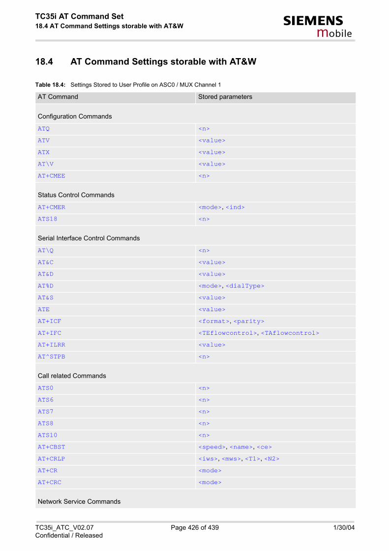
TC35i AT Command Set18.4 AT Command Settings storable with AT&W s
mobile
18.4 AT Command Settings storable with AT&W
Table 18.4: Settings Stored to User Profile on ASC0 / MUX Channel 1
AT Command Stored parameters
Configuration Commands
ATQ <n>
ATV <value>
ATX <value>
AT\V <value>
AT+CMEE <n>
Status Control Commands
AT+CMER <mode>, <ind>
ATS18 <n>
Serial Interface Control Commands
AT\Q <n>
AT&C <value>
AT&D <value>
AT%D <mode>, <dialType>
AT&S <value>
ATE <value>
AT+ICF <format>, <parity>
AT+IFC <TEflowcontrol>, <TAflowcontrol>
AT+ILRR <value>
AT^STPB <n>
Call related Commands
ATS0 <n>
ATS6 <n>
ATS7 <n>
ATS8 <n>
ATS10 <n>
AT+CBST <speed>, <name>, <ce>
AT+CRLP <iws>, <mws>, <T1>, <N2>
AT+CR <mode>
AT+CRC <mode>
Network Service Commands
TC35i_ATC_V02.07 Page 426 of 439 1/30/04Confidential / Released

TC35i AT Command Set18.4 AT Command Settings storable with AT&W s
mobile
Table 18.5: Settings Stored to User Profile on MUX Channels 2 and 3
AT+COPS <format>
AT+CREG <n>
Supplementary Service Commands
AT^SACM <n>
AT+CLIP <n>
FAX Commands
AT+FCLASS <n>
Short Message Service (SMS) Commands
AT+CMGF <mode>
AT+CNMI <mode>, <mt>, <bm>, <ds>, <bfr>
AT+CSDH <show>
AT^SMGO <n>
SIM related Commands
AT^SCKS <mode>
AT^SSET <n>
Miscellaneous Commands
ATS3 <n>
ATS4 <n>
ATS5 <n>
AT Command Stored parameters
Configuration Commands
ATQ <n>
ATV <value>
ATX <value>
AT+CMEE <n>
Status Control Commands
AT+CMER <mode>, <ind>
Serial Interface Control Commands
AT\Q <n>
AT Command Stored parameters
TC35i_ATC_V02.07 Page 427 of 439 1/30/04Confidential / Released

TC35i AT Command Set18.4 AT Command Settings storable with AT&W s
mobile
AT&C <value>
AT&D <value>
AT%D <mode>, <dialType>
AT&S <value>
ATE <value>
AT+ICF <format>, <parity>
AT+IFC <TEflowcontrol>, <TAflowcontrol>
Call related Commands
ATS0 <n>
AT+CRC <mode>
Network Service Commands
AT+COPS <format>
AT+CREG <n>
Supplementary Service Commands
AT^SACM <n>
AT+CLIP <n>
Short Message Service (SMS) Commands
AT+CMGF <mode>
AT+CNMI <mode>, <mt>, <bm>, <ds>, <bfr>
AT+CSDH <show>
AT^SMGO <n>
SIM related Commands
AT^SCKS <mode>
AT^SSET <n>
Miscellaneous Commands
ATS3 <n>
ATS4 <n>
ATS5 <n>
AT Command Stored parameters
TC35i_ATC_V02.07 Page 428 of 439 1/30/04Confidential / Released

TC35i AT Command Set18.5 Factory Default Settings Restorable with AT&F s
mobile
18.5 Factory Default Settings Restorable with AT&F
Table 18.6: Factory Default Settings Restorable with AT&F
AT Command Factory Defaults
Configuration Commands
ATQ <n>=0
ATV <value>=1
ATX <value>=4
AT\V <value>=1
AT+CFUN <fun>=1
AT+CMEE <n>=0
AT+CSCS <chset>="GSM"
AT^SM20 <CallMode>=1, <CmgwMode>=1
Status Control Commands
AT+CMER <mode>=0, <keyp>=0, <disp>=0, <ind>=0, <bfr>=0
ATS18 <n>=0
Serial Interface Control Commands
AT\Q <n>=0
AT&C <value>=1
AT&D <value>=2
AT%D <mode>=0, <dialType>=" "
AT&S <value>=0
ATE <value>=1
AT+ILRR <value>=0
AT^STPB <n>=0
Call related Commands
ATD><mem><n> <mem>="SM"
ATS0 <n>=000
ATS6 <n>=000
ATS7 <n>=060
ATS10 <n>=002
AT+CBST <speed>=7, <name>=0, <ce>=1
AT+CRLP <iws>=61, <mws>=61, <T1>=78, <N2>=6
AT+CR <mode>=0
AT+CRC <mode>=0
TC35i_ATC_V02.07 Page 429 of 439 1/30/04Confidential / Released

TC35i AT Command Set18.5 Factory Default Settings Restorable with AT&F s
mobile
Network Service Commands
AT+COPS <format>=0
AT+CREG <n>=0
AT^SALS <view>=0
Supplementary Service Commands
AT^SACM <n>=0
AT+CLIP <n>=0
AT+CSSN <n>=0, <m>=0
AT+CUSD <n>=0
FAX Commands
AT+FCLASS <n>=0
Short Message Service (SMS) Commands
AT+CMGF <mode>=0
AT+CNMI <mode>=0, <mt>=0, <bm>=0, <ds>=0, <bfr>=1
AT+CSDH <show>=0
AT+CSMP <fo>=17, <vp>=167, <dcs>=0, <pid>=0
AT^SMGO <n>=0
AT^SSCONF <ra>=0, <ff>=0
AT^SSDA <da>=0
AT^SSMSS <seq>=0
SIM related Commands
AT^SCKS <mode>=0
AT^SSET <n>=0
Phonebook Commands
AT+CPBS <storage>="SM"
AT^SPBD <storage>="SM"
AT^SPBS <internal-counter>=0
Audio Commands
AT+VTD <duration>=1
Hardware related Commands
AT^SCTM <n>=0, <p>=0
AT Command Factory Defaults
TC35i_ATC_V02.07 Page 430 of 439 1/30/04Confidential / Released

TC35i AT Command Set18.5 Factory Default Settings Restorable with AT&F s
mobile
Miscellaneous Commands
ATS3 <n>=013
ATS4 <n>=010
ATS5 <n>=008
AT Command Factory Defaults
TC35i_ATC_V02.07 Page 431 of 439 1/30/04Confidential / Released

TC35i AT Command Set18.6 Summary of Unsolicited Result Codes (URC) s
mobile
18.6 Summary of Unsolicited Result Codes (URC)
Table 18.7: Summary of Unsolicited Result Codes (URC)
AT Command URC
Configuration Commands
AT^SMSO ^SHUTDOWN
AT^SCFG ^SCFG: : "AutoExec", <AutoExecState>, <AutoExecType>, <AutoExecIndex>, <AutoExecMode>, <AutoExecATC>
Status Control Commands
AT+CMER +CIEV: <indDescr>, <indValue>
AT+CRC +CRING: <type>
Network Service Commands
AT+CREG +CREG: <stat>
AT+CREG +CREG: <stat>[, <lac>, <ci>]
AT^SALS view: <line>
Supplementary Service Commands
AT^SACM +CCCM: <ccm>
AT+CCWA +CCWA: <calling number>, <type of number>, <class>, , <CLI validity>
AT+CCWA ^SCWA
AT+CLIP +CLIP: <number>, <type>, , , , <CLI validity>
AT+CLIP +CLIP: <number>, <type>
AT+CSSN +CSSI: <code 1>
AT+CSSN +CSSU: <code 2>
AT+CUSD +CUSD: <m>[<str>[<dcs>]]
Short Message Service (SMS) Commands
AT+CNMI +CMTI: <mem3>, <index>
AT+CNMI +CMT: <length><CR><LF><pdu>
AT+CNMI +CMT: <oa>, <scts>[, <tooa>, <fo>, <pid>, <dcs>, <sca>, <tosca>, <length>]<CR><LF><data>
AT+CNMI +CBM: <length><CR><LF><pdu>
AT+CNMI +CBM: <sn>, <mid>, <dcs>, <page>, <pages><CR><LF><data>
AT+CNMI +CDS: <length><CR><LF><pdu>
AT+CNMI +CDS: <fo>, <mr>[, <ra>][, <tora>], <scts>, <dt>, <st>
AT+CNMI +CDSI: <mem3>, <index>
AT^SMGO ^SMGO: <mode>
TC35i_ATC_V02.07 Page 432 of 439 1/30/04Confidential / Released

TC35i AT Command Set18.6 Summary of Unsolicited Result Codes (URC) s
mobile
SIM related Commands
AT^SCKS ^SCKS: <SimStatus>
AT^SSET ^SSIM READY
SIM Application Toolkit (SAT) Commands
^SSTN ^SSTN: <cmdType>
^SSTN ^SSTN: <cmdTerminateValue>
^SSTN ^SSTN: 254
^SSTN ^SSTN: 255
Hardware related Commands
AT+CALA +CALA: <text>
AT^SBC ^SBC: Undervoltage
AT^SBC ^SBC: Overvoltage warning
AT^SBC ^SBC: Overvoltage shutdown
AT^SCTM ^SCTM_A: <m>
AT^SCTM ^SCTM_B: <m>
AT Command URC
TC35i_ATC_V02.07 Page 433 of 439 1/30/04Confidential / Released
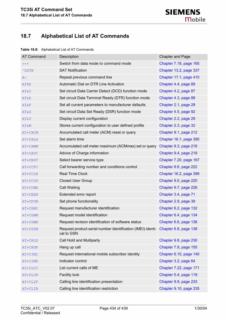
TC35i AT Command Set18.7 Alphabetical List of AT Commands s
mobile
18.7 Alphabetical List of AT Commands
Table 18.8: Alphabetical List of AT Commands
AT Command Description Chapter and Page
+++ Switch from data mode to command mode Chapter 7.18, page 165
^SSTN SAT Notification Chapter 13.2, page 337
A/ Repeat previous command line Chapter 17.1, page 410
AT%D Automatic Dial on DTR Line Activation Chapter 4.4, page 89
AT&C Set circuit Data Carrier Detect (DCD) function mode Chapter 4.2, page 87
AT&D Set circuit Data Terminal Ready (DTR) function mode Chapter 4.3, page 88
AT&F Set all current parameters to manufacturer defaults Chapter 2.1, page 28
AT&S Set circuit Data Set Ready (DSR) function mode Chapter 4.5, page 92
AT&V Display current configuration Chapter 2.2, page 29
AT&W Stores current configuration to user defined profile Chapter 2.3, page 32
AT+CACM Accumulated call meter (ACM) reset or query Chapter 9.1, page 212
AT+CALA Set alarm time Chapter 16.1, page 395
AT+CAMM Accumulated call meter maximum (ACMmax) set or query Chapter 9.3, page 216
AT+CAOC Advice of Charge information Chapter 9.4, page 218
AT+CBST Select bearer service type Chapter 7.20, page 167
AT+CCFC Call forwarding number and conditions control Chapter 9.6, page 222
AT+CCLK Real Time Clock Chapter 16.2, page 399
AT+CCUG Closed User Group Chapter 9.5, page 220
AT+CCWA Call Waiting Chapter 9.7, page 226
AT+CEER Extended error report Chapter 3.4, page 71
AT+CFUN Set phone functionality Chapter 2.9, page 39
AT+CGMI Request manufacturer identification Chapter 6.2, page 132
AT+CGMM Request model identification Chapter 6.4, page 134
AT+CGMR Request revision identification of software status Chapter 6.6, page 136
AT+CGSN Request product serial number identification (IMEI) identi-cal to GSN
Chapter 6.8, page 138
AT+CHLD Call Hold and Multiparty Chapter 9.8, page 230
AT+CHUP Hang up call Chapter 7.9, page 155
AT+CIMI Request international mobile subscriber identity Chapter 6.10, page 140
AT+CIND Indicator control Chapter 3.2, page 64
AT+CLCC List current calls of ME Chapter 7.22, page 171
AT+CLCK Facility lock Chapter 5.4, page 119
AT+CLIP Calling line identification presentation Chapter 9.9, page 233
AT+CLIR Calling line identification restriction Chapter 9.10, page 235
TC35i_ATC_V02.07 Page 434 of 439 1/30/04Confidential / Released

TC35i AT Command Set18.7 Alphabetical List of AT Commands s
mobile
AT+CLVL Loudspeaker volume level Chapter 15.4, page 367
AT+CMEE Report mobile equipment error Chapter 2.12, page 46
AT+CMER Mobile Equipment Event Reporting Chapter 3.1, page 61
AT+CMGC Send an SMS command Chapter 11.2, page 279
AT+CMGD Delete SMS message Chapter 11.3, page 280
AT+CMGF Select SMS message format Chapter 11.4, page 281
AT+CMGL List SMS messages from preferred store Chapter 11.5, page 282
AT+CMGR Read SMS messages Chapter 11.6, page 284
AT+CMGS Send SMS message Chapter 11.7, page 286
AT+CMGW Write SMS messages to memory Chapter 11.8, page 288
AT+CMSS Send SMS messages from storage Chapter 11.9, page 290
AT+CMUT Mute control Chapter 15.5, page 369
AT+CMUX Enter multiplex mode Chapter 4.11, page 103
AT+CNMA New SMS message acknowledge to ME/TE, only phase 2+
Chapter 11.10, page 291
AT+CNMI New SMS message indications Chapter 11.11, page 293
AT+COPN Read operator names Chapter 8.1, page 184
AT+COPS Operator selection Chapter 8.2, page 185
AT+CPAS Mobile equipment activity status Chapter 3.6, page 84
AT+CPBR Read from Phonebook Chapter 14.2, page 344
AT+CPBS Select phonebook memory storage Chapter 14.3, page 347
AT+CPBW Write into Phonebook Chapter 14.4, page 349
AT+CPIN Enter PIN Chapter 5.1, page 109
AT+CPIN2 Enter PIN2 Chapter 5.2, page 113
AT+CPMS Preferred SMS message storage Chapter 11.12, page 297
AT+CPUC Price per unit and currency table Chapter 9.11, page 237
AT+CPWD Change Password Chapter 5.6, page 126
AT+CR Service reporting control Chapter 7.23, page 174
AT+CRC Set Cellular Result Codes for incoming call indication Chapter 7.24, page 176
AT+CREG Network registration Chapter 8.3, page 187
AT+CRLP Select radio link protocol param. for orig. non-transparent data call
Chapter 7.21, page 169
AT+CRSM Restricted SIM Access Chapter 12.1, page 326
AT+CSCA SMS service centre address Chapter 11.13, page 300
AT+CSCB Select Cell Broadcast Message Indication Chapter 11.14, page 301
AT+CSCS Select TE character set Chapter 2.13, page 51
AT+CSDH Show SMS text mode parameters Chapter 11.15, page 303
AT Command Description Chapter and Page
TC35i_ATC_V02.07 Page 435 of 439 1/30/04Confidential / Released

TC35i AT Command Set18.7 Alphabetical List of AT Commands s
mobile
AT+CSMP Set SMS text mode parameters Chapter 11.16, page 304
AT+CSMS Select Message Service Chapter 11.17, page 306
AT+CSNS Single Numbering Scheme Chapter 7.25, page 178
AT+CSQ Signal quality Chapter 8.4, page 190
AT+CSSN Supplementary service notifications Chapter 9.12, page 239
AT+CUSD Supplementary service notifications Chapter 9.13, page 241
AT+CXXCID Display card ID Chapter 12.5, page 334
AT+FBADLIN Bad Line Treshold Chapter 10.2, page 246
AT+FBADMUL Error Threshold Multiplier Chapter 10.3, page 247
AT+FBOR Query data bit order Chapter 10.4, page 248
AT+FCIG Query or set the Local polling id Chapter 10.5, page 249
AT+FCLASS Fax: Select, read or test service class Chapter 10.6, page 250
AT+FCQ Copy Quality Checking Chapter 10.7, page 252
AT+FCR Capability to receive Chapter 10.8, page 253
AT+FDCC Query or set capabilities Chapter 10.9, page 254
AT+FDFFC Data Compression Format Conversion Chapter 10.10, page 255
AT+FDIS Query or set session parameters Chapter 10.11, page 256
AT+FDR Begin or continue phase C data reception Chapter 10.12, page 257
AT+FDT Data Transmission Chapter 10.13, page 258
AT+FET End a page or document Chapter 10.14, page 259
AT+FK Kill operation, orderly FAX abort Chapter 10.15, page 260
AT+FLID Query or set the Local Id setting capabilities Chapter 10.16, page 261
AT+FMDL identify Product Model Chapter 10.17, page 262
AT+FMFR Request Manufacturer Identification Chapter 10.18, page 263
AT+FOPT Set bit order independently Chapter 10.19, page 264
AT+FPHCTO DTE Phase C Response Timeout Chapter 10.20, page 265
AT+FREV Identify Product Revision Chapter 10.21, page 266
AT+FRH Receive Data Using HDLC Framing Chapter 10.22, page 267
AT+FRM Receive Data Chapter 10.23, page 268
AT+FRS Receive Silence Chapter 10.24, page 269
AT+FTH Transmit Data Using HDLC Framing Chapter 10.25, page 270
AT+FTM Transmit Data Chapter 10.26, page 271
AT+FTS Stop Transmission and Wait Chapter 10.27, page 272
AT+FVRFC Vertical resolution format conversion Chapter 10.28, page 273
AT+GCAP Request complete TA capabilities list Chapter 2.11, page 45
AT+GMI Request manufacturer identification Chapter 6.3, page 133
AT+GMM Request TA model identification Chapter 6.5, page 135
AT Command Description Chapter and Page
TC35i_ATC_V02.07 Page 436 of 439 1/30/04Confidential / Released

TC35i AT Command Set18.7 Alphabetical List of AT Commands s
mobile
AT+GMR Request TA revision identification of software status Chapter 6.7, page 137
AT+GSN Request TA serial number identification(IMEI) Chapter 6.9, page 139
AT+ICF Serial Interface Character Framing Chapter 4.7, page 94
AT+IFC Set Flow Control separately for data directions Chapter 4.8, page 96
AT+ILRR Set TE-TA local rate reporting Chapter 4.9, page 98
AT+IPR Set fixed local rate Chapter 4.10, page 100
AT+VTD Tone duration Chapter 15.6, page 370
AT+VTS DTMF and tone generation Chapter 15.7, page 371
AT+WS46 Select wireless network Chapter 3.7, page 85
AT\Q Flowcontrol Chapter 4.1, page 86
AT\V Set CONNECT result code format Chapter 2.7, page 37
AT^MONI Monitor idle mode and dedicated mode Chapter 8.7, page 199
AT^MONP Monitor neighbour cells Chapter 8.8, page 203
AT^SACM Advice of charge and query of ACM and ACMmax Chapter 9.2, page 214
AT^SAIC Audio Interface Configuration Chapter 15.8, page 373
AT^SALS Alternate Line Service Chapter 8.9, page 205
AT^SBC Battery charging / discharging and charge control Chapter 16.3, page 400
AT^SBV Battery/Supply Voltage Chapter 16.4, page 403
AT^SCFG Extended Configuration Settings Chapter 2.14, page 53
AT^SCID Display SIM card identification number Chapter 12.4, page 333
AT^SCKS Query SIM and Chip Card Holder Status Chapter 12.2, page 329
AT^SCML List Concatenated SMS messages from preferred store Chapter 11.18, page 308
AT^SCMR Read concatenated SMS messages Chapter 11.19, page 310
AT^SCMS Send concatenated SMS messages Chapter 11.20, page 312
AT^SCMW Write concatenated SMS messages to memory Chapter 11.21, page 313
AT^SCNI List Call Number Information Chapter 7.26, page 180
AT^SCTM Set critical operating temperature presentation mode or query temperature
Chapter 16.5, page 404
AT^SDLD Delete the 'last number redial' memory Chapter 14.9, page 363
AT^SHOM Display Homezone Chapter 8.10, page 207
AT^SHUP Hang up call(s) indicating a specific GSM04.08 release cause
Chapter 7.10, page 156
AT^SIND Extended Indicator Control Chapter 3.3, page 68
AT^SLCD Display Last Call Duration Chapter 7.27, page 182
AT^SLCK Facility lock Chapter 5.5, page 125
AT^SLMS List SMS Memory Storage Chapter 11.22, page 314
AT^SM20 Set M20 compatibility mode Chapter 2.15, page 59
AT Command Description Chapter and Page
TC35i_ATC_V02.07 Page 437 of 439 1/30/04Confidential / Released

TC35i AT Command Set18.7 Alphabetical List of AT Commands s
mobile
AT^SMGL List SMS messages from preferred store without setting status to REC READ
Chapter 11.23, page 316
AT^SMGO Set or query SMS overflow presentation mode or query SMS overflow
Chapter 11.24, page 318
AT^SMGR Read SMS message without setting status to REC READ Chapter 11.25, page 320
AT^SMONC Cell Monitoring Chapter 8.5, page 192
AT^SMOND Selective Cell Monitoring Chapter 8.6, page 194
AT^SMSO Switch off mobile station Chapter 2.10, page 44
AT^SNFA Set or query of microphone attenuation Chapter 15.9, page 375
AT^SNFD Set audio parameters to manufacturer default values Chapter 15.10, page 377
AT^SNFI Set microphone path parameters Chapter 15.11, page 378
AT^SNFM Mute microphone Chapter 15.12, page 380
AT^SNFO Set audio output (= loudspeaker path) parameter Chapter 15.13, page 382
AT^SNFPT Set progress tones Chapter 15.14, page 384
AT^SNFS Select audio hardware set Chapter 15.15, page 385
AT^SNFV Set loudspeaker volume Chapter 15.16, page 389
AT^SNFW Write audio setting in non-volatile store Chapter 15.17, page 391
AT^SPBC Search the first entry in the sorted telephone book Chapter 14.5, page 352
AT^SPBD Purge phonebook memory storage Chapter 14.6, page 354
AT^SPBG Read current Phonebook entries Chapter 14.7, page 356
AT^SPBS Step through the selected phonebook alphabetically Chapter 14.8, page 359
AT^SPIC Display PIN counter Chapter 5.3, page 116
AT^SPLM Read the PLMN list Chapter 8.11, page 208
AT^SPLR Read entry from the preferred operators list Chapter 8.12, page 209
AT^SPLW Write an entry to the preferred operators list Chapter 8.13, page 211
AT^SPWD Change Password Chapter 5.7, page 130
AT^SRTC Ring tone configuration Chapter 15.18, page 392
AT^SSCONF SMS Configuration Chapter 11.26, page 321
AT^SSDA Set SMS Display Availability Chapter 11.27, page 323
AT^SSET Indicate SIM data ready Chapter 12.3, page 331
AT^SSMSS Set Short Message Storage Sequence Chapter 11.28, page 325
AT^SSTA SAT Interface Activation Chapter 13.1, page 335
AT^SSTGI SAT Get Information Chapter 13.3, page 339
AT^SSTR SAT Response Chapter 13.4, page 341
AT^SSYNC Configure SYNC Pin Chapter 16.6, page 407
AT^STCD Display Total Call Duration Chapter 7.28, page 183
AT^STPB Transmit Parity Bit (for 7E1 and 7O1 only) Chapter 4.12, page 107
AT Command Description Chapter and Page
TC35i_ATC_V02.07 Page 438 of 439 1/30/04Confidential / Released

TC35i AT Command Set18.7 Alphabetical List of AT Commands s
mobile
ATA Answer a call Chapter 7.1, page 141
ATD Mobile originated call to dial a number Chapter 7.2, page 143
ATD><mem><n> Originate call to phone number in memory Chapter 7.3, page 146
ATD><n> Originate call to phone number selected from active mem-ory
Chapter 7.4, page 148
ATD><str> Originate call to phone number in memory with corre-sponding field
Chapter 7.5, page 150
ATDI Mobile originated call to dialable ISDN number <n> Chapter 7.6, page 152
ATDL Redial last telephone number used Chapter 7.7, page 153
ATE Enable command echo Chapter 4.6, page 93
ATH Disconnect existing connection Chapter 7.8, page 154
ATI Display product identification information Chapter 6.1, page 131
ATL Set monitor speaker loudness Chapter 15.2, page 365
ATM Set monitor speaker mode Chapter 15.3, page 366
ATO Switch from command mode to data mode Chapter 7.17, page 164
ATP Select pulse dialing Chapter 7.16, page 163
ATQ Set result code presentation mode Chapter 2.4, page 33
ATS0 Set number of rings before automatically answering the call
Chapter 7.11, page 158
ATS10 Set disconnect delay after indicating the absence of data carrier
Chapter 7.15, page 162
ATS18 Extended call release report Chapter 3.5, page 82
ATS3 Write command line termination character Chapter 17.2, page 411
ATS4 Set response formatting character Chapter 17.3, page 412
ATS5 Write command line editing character Chapter 17.4, page 413
ATS6 Set pause before blind dialing Chapter 7.12, page 159
ATS7 Set number of seconds to wait for connection completion Chapter 7.13, page 160
ATS8 Set number of seconds to wait for comma dialing modifier Chapter 7.14, page 161
ATT Select tone dialing Chapter 7.19, page 166
ATV Set result code format mode Chapter 2.5, page 34
ATX Set CONNECT result code format and call monitoring Chapter 2.6, page 36
ATZ Set all current parameters to user defined profile Chapter 2.8, page 38
AT Command Description Chapter and Page
TC35i_ATC_V02.07 Page 439 of 439 1/30/04Confidential / Released


![AT Reference Guide - Multi-Tech Systems, Inc.€¦ · DE910- Series AT commands reference guide – AT commands [...]](https://static.fdocuments.net/doc/165x107/6062516d02f817666972114c/at-reference-guide-multi-tech-systems-inc-de910-series-at-commands-reference.jpg)