
TC3500/TC3700 Series Tire Changer Operation Instructions TC3700... · 2019-12-13 · Low Profile...
57
Copyright 1998 - 2011 Hunter Engineering Company OPERATION INSTRUCTIONS Form 4352-T, 11-08c Supersedes Form 4352-T, 11-08 TC3500/TC3700 Series Tire Changer TC3500 / TC3500-SS / TC3510 / TC3700
Transcript of TC3500/TC3700 Series Tire Changer Operation Instructions TC3700... · 2019-12-13 · Low Profile...

Copyright 1998 - 2011 Hunter Engineering Company
OPERATION INSTRUCTIONS Form 4352-T, 11-08c
Supersedes Form 4352-T, 11-08
TC3500/TC3700 Series Tire Changer
TC3500 / TC3500-SS / TC3510 / TC3700

OWNER INFORMATION
Model Number _____________________________________________________________________
Serial Number _____________________________________________________________________
Date Installed ______________________________________________________________________
Service and Parts Representative ______________________________________________________
Phone Number _____________________________________________________________________
Sales Representative ________________________________________________________________
Phone Number _____________________________________________________________________
Concept and Procedure Explanation
Safety Precautions Trained Declined
Warning and Caution Labels
Bead Roller
Maintenance and Performance Checks Trained Declined
Air Pressure and Volume Check
Checking Arm Calibration to Rims
Rollers Parallel to Rim/Reference Gauge
Checking Angle of Rollers to Center Support
Adjustment and Filling of Oilers
Oil Type/Lubrication Fittings
Mounting Head and Rubber Pad Inspection (on TC3500-SS models)
Internal Clamping (TC3500-SS & TC3510 Only) Trained Declined
Rubber Pad Positioning
Conical Rims/Use of Rim Securing Device
Steel Jaw Use
External Clamping (TC3500-SS & TC3510 Only) Trained Declined
Rubber Jaw Positioning
Clamp Without Center Support
TC3700 Wheel Clamping Trained Declined
Standard Wheel
Reverse Drop Center Wheel
Column Adjustment
Bead Loosening Trained Declined
Standard Wheels
Low Profile Wheels
Cylindrical Wheels
Drop Center Identification and Tire Lubrication
Side Shovel Operation (on TC3500-SS, TC3510 & TC3700 models)
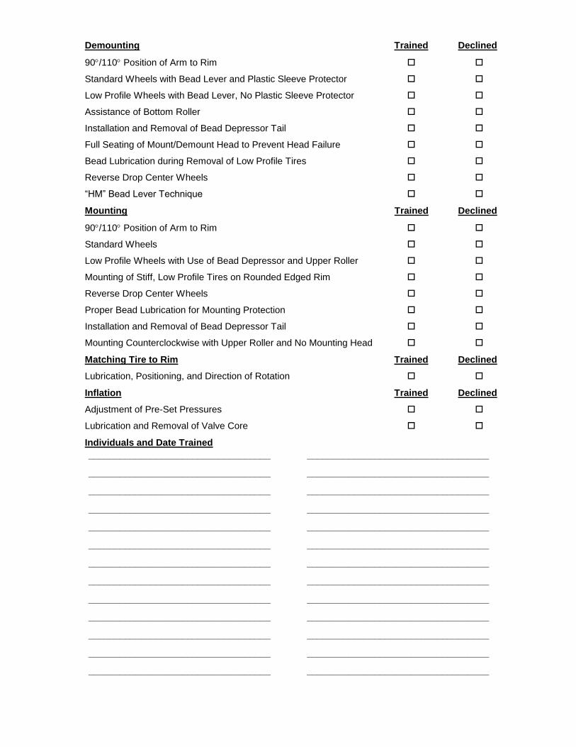
Demounting Trained Declined
90/110 Position of Arm to Rim
Standard Wheels with Bead Lever and Plastic Sleeve Protector
Low Profile Wheels with Bead Lever, No Plastic Sleeve Protector
Assistance of Bottom Roller
Installation and Removal of Bead Depressor Tail
Full Seating of Mount/Demount Head to Prevent Head Failure
Bead Lubrication during Removal of Low Profile Tires
Reverse Drop Center Wheels
“HM” Bead Lever Technique
Mounting Trained Declined
90/110 Position of Arm to Rim
Standard Wheels
Low Profile Wheels with Use of Bead Depressor and Upper Roller
Mounting of Stiff, Low Profile Tires on Rounded Edged Rim
Reverse Drop Center Wheels
Proper Bead Lubrication for Mounting Protection
Installation and Removal of Bead Depressor Tail
Mounting Counterclockwise with Upper Roller and No Mounting Head
Matching Tire to Rim Trained Declined
Lubrication, Positioning, and Direction of Rotation
Inflation Trained Declined
Adjustment of Pre-Set Pressures
Lubrication and Removal of Valve Core
Individuals and Date Trained
___________________________________ ___________________________________
___________________________________ ___________________________________
___________________________________ ___________________________________
___________________________________ ___________________________________
___________________________________ ___________________________________
___________________________________ ___________________________________
___________________________________ ___________________________________
___________________________________ ___________________________________
___________________________________ ___________________________________
___________________________________ ___________________________________
___________________________________ ___________________________________
___________________________________ ___________________________________
___________________________________ ___________________________________


TC3500/TC3700 Series Tire Changer Operation Instructions Contents i
CONTENTS
1. GETTING STARTED ....................................................................................... 7 1.1 Introduction ............................................................................................................. 7 1.2 For Your Safety ....................................................................................................... 7
Hazard Definitions .................................................................................................. 7 IMPORTANT SAFETY INSTRUCTIONS ............................................................... 8 TC3500 Tire Changer-Decal Placement ................................................................ 9 TC3710 Tire Changer-Decal Placement .............................................................. 11
1.3 Wheel Clamping Pedal (TC3500-SS/TC3510) ..................................................... 12 1.4 Tire Bead Loosening / Wheel Rotation Pedal (TC3500-SS) ................................ 12 1.5 Tire Bead Loosening Pedal (TC3510/TC3700) .................................................... 13 1.6 Wheel Rotation Pedal ........................................................................................... 13 1.7 Air Inflation Pedal .................................................................................................. 13 1.8 Inflator and Pressure Limiter ................................................................................ 13 1.9 Command Unit ...................................................................................................... 14 1.10 Equipment Components ..................................................................................... 15
TC3500 ................................................................................................................ 15 TC3500-SS .......................................................................................................... 16 TC3510 ................................................................................................................ 17 TC3700 ................................................................................................................ 18
2. BASIC PROCEDURES ................................................................................. 19 2.1 Side Shovel Bead Loosening (TC3500-SS/3510/3700 Models) ........................... 19 2.2 Placing Wheel on TC3500-SS/TC3510 ................................................................ 19
Clamping the Wheel from Inside of Rim .............................................................. 20 Clamping the Wheel from Outside of Rim ........................................................... 22 Clamping Reverse Drop Center Wheels .............................................................. 23
2.3 Placing Wheel on TC3700 .................................................................................... 23 Column Adjustment .............................................................................................. 23 Center Support Height Adjustment ...................................................................... 24 Standard Wheels ................................................................................................. 24 Reverse Drop Center Wheels .............................................................................. 26
2.4 Bead Loosening Standard Rim and Tire .............................................................. 27 2.5 Demounting Standard Tires from Rim .................................................................. 28 2.6 Mounting Standard Tire to Rim ............................................................................. 30
Precautionary Notes ............................................................................................. 31 2.7 Tire Inflation .......................................................................................................... 31
TC3500 & TC3500-SS Models:............................................................................ 32 TC3510/TC3700 Models: ..................................................................................... 32
2.8 Removal of Wheel from TC3500-SS/TC3700 ...................................................... 34 2.9 Removal of Wheel from TC3700 .......................................................................... 34
3. ADVANCED PROCEDURES ........................................................................ 35 3.1 Advanced Bead Loosening Procedures ............................................................... 35
Bead Loosening Soft Sidewall, Tall Profile Tires ................................................. 35 Bead Loosening Tough, Low Profile Tires ........................................................... 36 Bead Loosening “AH” Wheels .............................................................................. 36
3.2 Advanced Demounting Procedures ...................................................................... 38 Using “HM” Bead Lever and Sleeve Protector ..................................................... 38 Using Bead Depressor “Tail” and Bottom Roller to Demount Upper Bead without Sleeve Protector ................................................................................................... 38 Using Force Multiplier, RP6-G1000A23 (Optional on TC3510) ........................... 42 Demounting Lower Bead without Sleeve Protector .............................................. 42

ii Contents TC3500/TC3700 Series Tire Changer Operation Instructions
Cylindrical Rims/Bead Loosening and Demounting Lower Bead ......................... 43 3.3 Advanced Mounting Procedures ........................................................................... 44
Mechanical Bead Pusher, RP6-2413 ................................................................... 44 Mounting of Stiff Sidewall, Low Profile Tires ........................................................ 45 Removal of Bead Depressor “Tail” ....................................................................... 47 Mounting Low Profile Tires on Rounded Edged Rims ......................................... 47
3.4 Mounting Stiff, Low Profile Tires on Rounded Edged Rims Only Using Rollers ... 48 3.5 Matching/Optimizing of Tire to Rim ...................................................................... 50 3.6 Optional Steel Mount/Demount Head Assembly (RP6-2654) ............................... 50
4. MAINTENANCE AND CALIBRATION .......................................................... 51 4.1 Maintenance Schedule ......................................................................................... 51 4.2 Maintenance Replacement Parts ......................................................................... 52 4.3 Calibrating and Adjusting the Position of the Column........................................... 52 4.4 Checking and Adjusting the Bead Rollers ............................................................ 53 4.5 Checking and Adjusting the Position of the Bead Breaker Arm ........................... 53
5. GLOSSARY .................................................................................................. 55 5.1 Rim Diagram ......................................................................................................... 55 5.2 Illustration of AH2 Rim (Asymmetrical Humps) “Bead Locking System” .............. 56 5.3 Illustrations of Various Rim Designs ..................................................................... 57
TC3500/TC3700 Series Tire Changer Operation Instructions Getting Started 7
1. GETTING STARTED
1.1 Introduction
This manual provides operation instructions and information required to maintain the TC3500/TC3700 series tire changer. An advanced operation section has been provided in “Advanced Procedures.”
“References”
This manual assumes that you are already familiar with the basics of tire changing. The first section provides the basic information to operate the TC3500/TC3700. The following sections contain detailed information about equipment, procedures, and maintenance. “Italics” are used to refer to specific parts of this manual that provide additional information or explanation. For example, Refer to “Equipment Components,” page 15. These references should be read for additional information to the instructions being presented.
The owner of the TC3500/TC3700 is solely responsible for arranging technical training. The TC3500/TC3700 is to be operated only by a qualified trained technician. Maintaining records of personnel trained is solely the responsibility of the owner or management.
1.2 For Your Safety
Hazard Definitions
Watch for these symbols:
CAUTION: Hazards or unsafe practices, which could result in minor personal injury, or product or property damage.
WARNING: Hazards or unsafe practices, which could result in
severe personal injury or death.
DANGER: Immediate hazards, which will result in severe personal
injury or death.
These symbols identify situations that could be detrimental to your safety and/or cause equipment damage.
8 Getting Started TC3500/TC3700 Series Tire Changer Operation Instructions
IMPORTANT SAFETY INSTRUCTIONS
NOTE: Operators of this equipment should review the Hunter Training video before use. A certification test is also available.
Read and follow all caution and warning labels affixed to equipment and tools.
Read and understand all instructions before operating this machine.
Misuse of this equipment can cause personal injury and shorten the life of the TC3500/TC3700.
To prevent accidents or damage to the TC3500/TC3700, use only Hunter recommended procedures and accessories.
Wear OSHA approved eye protection while operating the TC3500/TC3700.
Wear non-slip safety footwear when operating the TC3500/TC3700.
Do not wear jewelry or loose clothing when operating theTC3500/TC3700.
Wear proper back support when lifting or removing wheel from the TC3500/TC3700.
WARNING: Keep hands and clothing clear of moving parts. Keep
hands clear of upper roller when bead loosening or
rotating clamped wheel. Do not lean or reach over tire
when inflating.
Never stand on theTC3500/TC3700.
WARNING: Do not exceed these pressure limitations:
SUPPLY LINE PRESSURE (from compressor) 220 PSI.
OPERATING PRESSURE (gauge on regulator) 145 PSI.
BEAD SEATING PRESSURE (gauge on hose) 40 PSI.
WARNING: Never mount a tire to a rim that is not the same diameter
(e.g., 16 1/2 inch tire mounting on a 16 inch rim).
DANGER: Activate air inflation ring only when seating bead.
CAUTION: Do not hose down or power wash electric tire changers.
Bleed air pressure from system before disconnecting supply line or other pneumatic components. Air is stored in a reservoir for operation of the inflation ring. Air pressure can be bled from the system by pulling up on the knob located on top of the regulator,
and then turning it counterclockwise.
Do not activate the air inflation ring/blast inflation hose if the tire is not properly clamped.
Do not operate TC3500/TC3700 with worn rubber or plastic parts.

TC3500/TC3700 Series Tire Changer Operation Instructions Getting Started 9
Wheels equipped with low tire pressure sensors or special tire and rim design may require certain procedures. Consult manufacturer’s service manuals.
Service and maintain machine regularly as outlined in “Maintenance and Calibration,” on page 51. For further information contact:
Hunter Engineering Company
11250 Hunter Drive
Bridgeton, Missouri 63044
1-800-448-6848
http://www.hunter.com
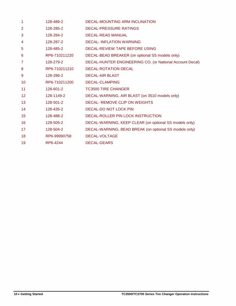
TC3500 Tire Changer-Decal Placement
TC3510 Shown
10 Getting Started TC3500/TC3700 Series Tire Changer Operation Instructions
1 128-489-2 DECAL-MOUNTING ARM INCLINATION
2 128-285-2 DECAL-PRESSURE RATINGS
3 128-284-2 DECAL-READ MANUAL
4 128-287-2 DECAL- INFLATION WARNING
5 128-485-2 DECAL-REVIEW TAPE BEFORE USING
6 RP6-710211220 DECAL-BEAD BREAKER (on optional SS models only)
7 128-279-2 DECAL-HUNTER ENGINEERING CO. (or National Account Decal)
8 RP6-710211210 DECAL-ROTATION DECAL
9 128-286-2 DECAL-AIR BLAST
10 RP6-710211200 DECAL-CLAMPING
11 128-601-2 TC3500 TIRE CHANGER
12 128-1149-2 DECAL-WARNING, AIR BLAST (on 3510 models only)
13 128-501-2 DECAL- REMOVE CLIP ON WEIGHTS
14 128-435-2 DECAL-DO NOT LOCK PIN
15 128-488-2 DECAL-ROLLER PIN LOCK INSTRUCTION
16 128-505-2 DECAL-WARNING, KEEP CLEAR (on optional SS models only)
17 128-504-2 DECAL-WARNING, BEAD BREAK (on optional SS models only)
18 RP6-99990758 DECAL-VOLTAGE
19 RP6-4244 DECAL-GEARS
TC3500/TC3700 Series Tire Changer Operation Instructions Getting Started 11
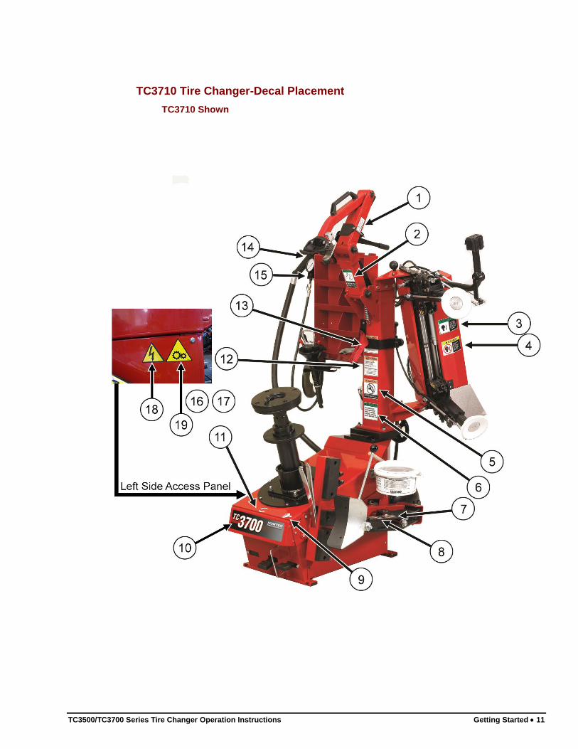
TC3710 Tire Changer-Decal Placement
TC3710 Shown
12 Getting Started TC3500/TC3700 Series Tire Changer Operation Instructions
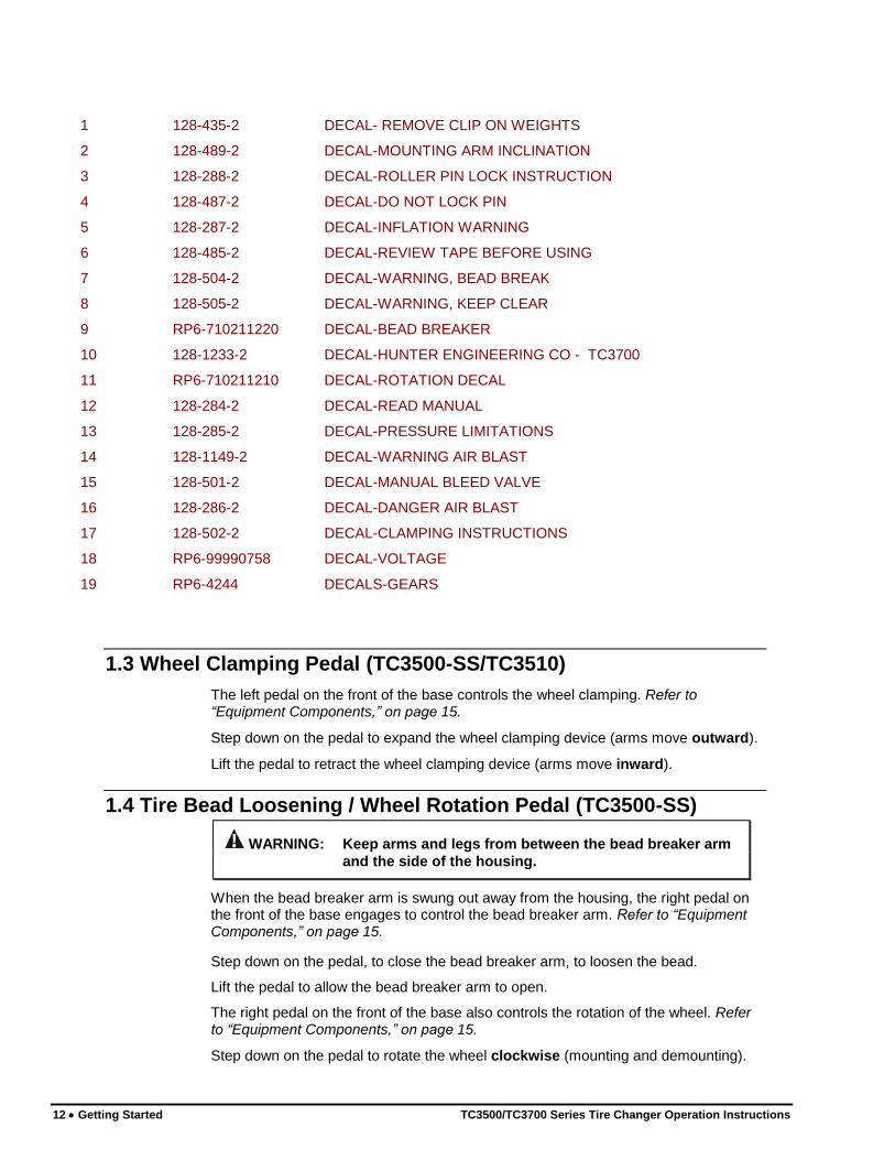
1 128-435-2 DECAL- REMOVE CLIP ON WEIGHTS
2 128-489-2 DECAL-MOUNTING ARM INCLINATION
3 128-288-2 DECAL-ROLLER PIN LOCK INSTRUCTION
4 128-487-2 DECAL-DO NOT LOCK PIN
5 128-287-2 DECAL-INFLATION WARNING
6 128-485-2 DECAL-REVIEW TAPE BEFORE USING
7 128-504-2 DECAL-WARNING, BEAD BREAK
8 128-505-2 DECAL-WARNING, KEEP CLEAR
9 RP6-710211220 DECAL-BEAD BREAKER
10 128-1233-2 DECAL-HUNTER ENGINEERING CO - TC3700
11 RP6-710211210 DECAL-ROTATION DECAL
12 128-284-2 DECAL-READ MANUAL
13 128-285-2 DECAL-PRESSURE LIMITATIONS
14 128-1149-2 DECAL-WARNING AIR BLAST
15 128-501-2 DECAL-MANUAL BLEED VALVE
16 128-286-2 DECAL-DANGER AIR BLAST
17 128-502-2 DECAL-CLAMPING INSTRUCTIONS
18 RP6-99990758 DECAL-VOLTAGE
19 RP6-4244 DECALS-GEARS
1.3 Wheel Clamping Pedal (TC3500-SS/TC3510)
The left pedal on the front of the base controls the wheel clamping. Refer to “Equipment Components,” on page 15.
Step down on the pedal to expand the wheel clamping device (arms move outward).
Lift the pedal to retract the wheel clamping device (arms move inward).
1.4 Tire Bead Loosening / Wheel Rotation Pedal (TC3500-SS)
WARNING: Keep arms and legs from between the bead breaker arm
and the side of the housing.
When the bead breaker arm is swung out away from the housing, the right pedal on the front of the base engages to control the bead breaker arm. Refer to “Equipment Components,” on page 15.
Step down on the pedal, to close the bead breaker arm, to loosen the bead.
Lift the pedal to allow the bead breaker arm to open.
The right pedal on the front of the base also controls the rotation of the wheel. Refer to “Equipment Components,” on page 15.
Step down on the pedal to rotate the wheel clockwise (mounting and demounting).

TC3500/TC3700 Series Tire Changer Operation Instructions Getting Started 13
Lift the pedal to rotate the wheel counterclockwise (bead loosening).
1.5 Tire Bead Loosening Pedal (TC3510/TC3700)
WARNING: Keep arms and legs from between the bead breaker arm
and the side of the housing.
The right pedal on the front of the base controls the side shovel. Refer to “Equipment Components,” on page 15.
Step down on the pedal, to close the bead breaker arm, to loosen the bead.
Release the pedal to allow the bead breaker arm to open.
1.6 Wheel Rotation Pedal
The right pedal on the TC3500 and TC3500-SS, the middle pedal on the TC3510, or the left pedal on the TC3700, on the front of the base controls the rotation of the wheel. Refer to “Equipment Components,” on page 15.
Step down on the pedal to rotate the wheel clockwise (mounting and demounting).
Lift the pedal to rotate the wheel counterclockwise (bead loosening and matching).
CAUTION: Keep hands clear of wheel, tire, and rollers during bead loosening.
1.7 Air Inflation Pedal
The pedal on the left side of the base is a two-stage design. Refer to “Equipment Components,” on page 15. The pedal controls the air going to the inflation hose and the dual air inflation ring.
CAUTION: Keep hands clear of wheel during sealing and seating of bead.
When operating air inflator, stand to the left side of the base. Do not stand in front of the TC3500/TC3700 while operating the air inflator.
Step down partially on the pedal to inflate tires through inflator hose.
Step down completely on the pedal to activate the air inflator ring (blast inflator nozzle on TC3510/TC3700) to seal tire beads.
The TC3500 and TC3500-SS feature a dual air inflation ring. When the diverter valve is pushed in, air will be directed through the inner ring. When the diverter valve is pulled out, air will be directed through the outer ring. Due to the wide variety of wheel and tire combinations, determining which rings works best for any particular wheel and tire combination will be by trial and error.
1.8 Inflator and Pressure Limiter
As a safety device, the pressure limiter prevents the operator from using excessive air pressure to seat the tire bead during tire inflation. Bead seating pressure should never exceed 40 psi. If tires being mounted require more than 40 psi for inflation pressure, the tire/wheel assembly should be removed from the tire changer, placed in an inflation cage, and inflated per manufacturer’s instructions.
While inflating the tire, the pressure gauge will read zero until the inflation pedal is released. At that time, the gauge will give the correct air pressure reading in the tire.
14 Getting Started TC3500/TC3700 Series Tire Changer Operation Instructions
1.9 Command Unit
The command unit governs all the movements necessary for complete bead roller operation. Refer to “Equipment Components,” on page 15.
The command unit is used to position the bead roller into the working position.
For proper operation of the command unit, place your hand over controller with index finger and middle finger over lever buttons. Push and pull the command unit to bring the rollers to the correct rim diameter.
The rim diameter that the bead rollers are set to is indicated on the scale of the handle support. The scale is only a reference. All rims differ in flange design.
The command unit has two pneumatic lever buttons:
Left button controls the upper bead roller arm assembly.
Right button controls the lower bead roller arm assembly.
Each button has three positions:
In first position, bead roller arms are retracted.
In second position, bead roller with air pressure lightly contacts the sidewall of the tire. The bead roller stays in this position until the button is depressed or retracted.
In third position, the bead roller applies hydraulic pressure to push the bead of the tire inward.
TC3500/TC3700 Series Tire Changer Operation Instructions Getting Started 15
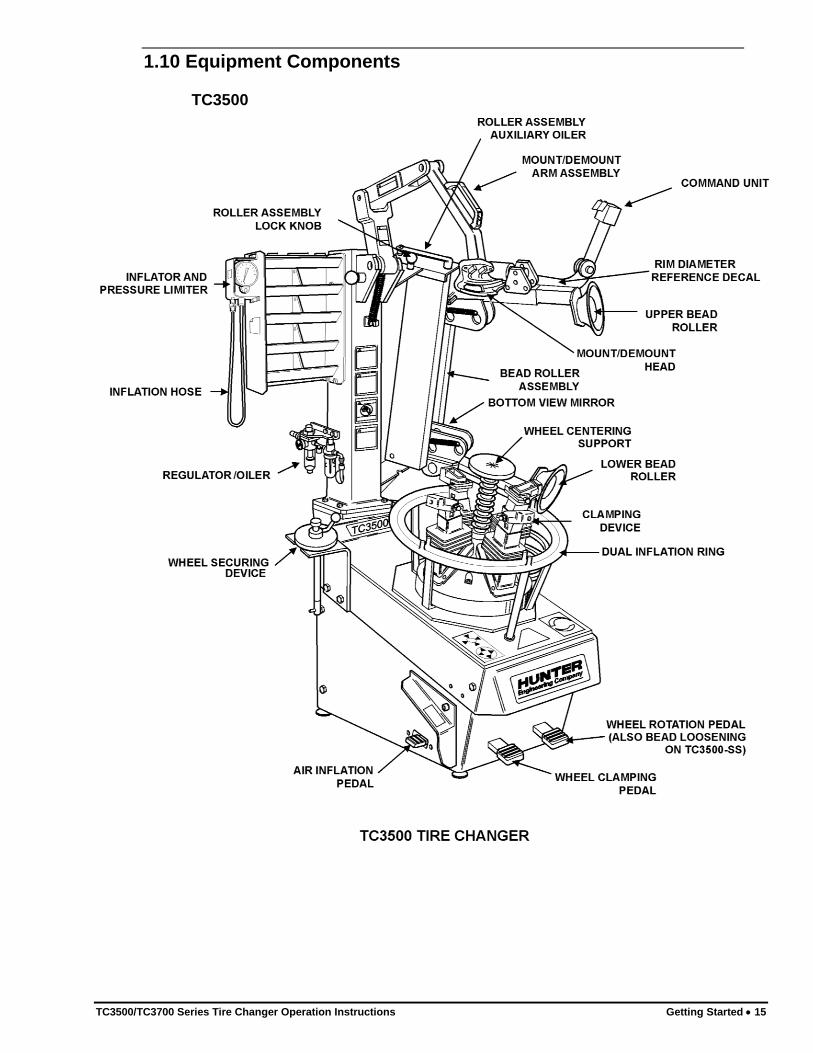
1.10 Equipment Components
TC3500

16 Getting Started TC3500/TC3700 Series Tire Changer Operation Instructions
TC3500-SS

TC3500/TC3700 Series Tire Changer Operation Instructions Getting Started 17
TC3510

18 Getting Started TC3500/TC3700 Series Tire Changer Operation Instructions
TC3700

TC3500/TC3700 Series Tire Changer Operation Instructions Basic Procedures 19
2. BASIC PROCEDURES
2.1 Side Shovel Bead Loosening (TC3500-SS/3510/3700 Models)
For bead loosening with rollers, refer to “Bead Loosening Standard Rim and Tire,” page 27.
Remove valve stem core and deflate tire completely.
WARNING: All air pressure inside the tire must be removed before
proceeding. Never attempt to loosen the bead until all air
is removed from the tire. Failure to remove all air from
tire may result in injury to operator, or damage to
equipment, tire, or wheel.
Remove all weights from the rim to protect the rim and to extend life of the mount/demount head.
Swing the bead breaker arm out and away from the housing.
Position the wheel against the side of the TC3500-SS/TC3510, between the bead breaker arm and the housing.
Swing the bead breaker arm toward the tire and position the blade two to three inches from the edge of the rim on the sidewall of the tire.
Step down on the right pedal. The bead breaker arm will be pulled toward the TC3500-SS/TC3510 to loosen the bead.
Lift and hold the right pedal up to disengage the bead breaker arm and then swing the arm to the open position. Once the arm has been swung to the open position, release the pedal.
If the bead has not completely loosened, rotate the wheel and repeat the bead loosening procedure at a different area on the tire.
Turn the wheel and loosen the opposite bead using the same procedure.
2.2 Placing Wheel on TC3500-SS/TC3510
The “tulip arm clamping” design is truly exclusive in its versatility and ability to grip wheels without damaging the surface finish.
Remove valve stem core and deflate tire completely (if not done previously).
WARNING: All air pressure inside the tire must be removed before
proceeding. Failure to remove all air from tire may result
in injury to operator or damage to equipment, tire, or
wheel.

20 Basic Procedures TC3500/TC3700 Series Tire Changer Operation Instructions
Remove all weights from the rim to protect the rim and extend life of mount/demount head (if not done previously).
Identify and recognize special wheel combinations such as Reverse Drop Center, AH2, and “Run-Flat” Extended Mobility Tires (EMT).
Identify the inner locations on the rim where the rubber pads of the clamping arms will come in contact in a parallel manner.
Clamping the Wheel from Inside of Rim
If servicing wheels larger than 20 inches in diameter, insert one adaptor, RP6-G1000A17, into each of the tulip arms.
TULIP ARM
ADAPTOR, RP6-6494
Verify that removable rubber coated jaws are not installed in clamping arms.
Lift the clamping (left) pedal to retract the clamping device.
NOTE: Periodically clean and degrease the rubber pads to remove dirt and debris before placing the wheel on the TC3500.
Place the wheel onto the spring-loaded, wheel-centering device.
Push down on the wheel to locate the desired area to which the rubber pads will be applied. Hold the wheel at this location until properly clamped.
Step down on the clamping pedal until the wheel is completely clamped by the rubber pads.
Verify that the entire face of the rubber pad contacts the rim. If the rubber pad is partially pushed against a sharp corner or radius on a rim, the clamping force will cause uneven pressure and eventually “chunk” the pads.
The amount of pressure being applied by the rubber pads to the rim can be increased or decreased by depressing or lifting the clamping pedal. Apply only enough pressure to keep the rim from rotating or coming loose during tire demounting/mounting. Weak rims (e.g. wire wheels, etc.) can be lightly clamped by applying minimal pressure.

TC3500/TC3700 Series Tire Changer Operation Instructions Basic Procedures 21
Verify that the wheel has been properly clamped and centered.
NOTE: On conical shaped rims, always clamp the rim at a position parallel to the feet to prevent slippage. If the rim clamping area is oily or wet, clean the backside of the rim or install the steel clamping jaws, RP6-2252, on the rubber pads to increase rim gripping ability or use the wheel securing device. Refer to “Installation of Optional Wheel Securing Device,” on page 21 or to “Installation of Steel Jaws,” on page 22.
Installation of Optional Wheel Securing Device
The wheel securing device, RP6-1485, may be used if clamping conical internal rim shapes, wet or oily rims, run-flat or stiff sidewall tires. The primary purpose of this
device is to prevent the rim from popping up during clamping. It is not to be used to
hold the wheel during bead loosening procedures.
Position the wheel securing device through the center hole of the rim until it has been inserted into the wheel centering support.
Insert the locking pin of wheel securing device into the center support nut by rotating
clockwise.
PLATE
LOCKING PIN
LOCKING RING
WHEEL SECURING DEVICE
Position plate and lock into place by rotating locking ring clockwise.
If lock pin will not engage, loosen clamping arms and reposition pin.

22 Basic Procedures TC3500/TC3700 Series Tire Changer Operation Instructions
CAUTION: The wheel securing device is not to be used as a safety related hold-down tool.
Installation of Steel Jaws
The steel clamping jaws, RP6-2252, may be used if the rim clamping area is oily or wet. Install the jaws onto the rubber pads to increase rim gripping ability.
Place a steel jaw onto a rubber pad of a centering arm.
Push the steel jaw completely onto the rubber pad.
Hand-tighten the bolt located on each side of the steel jaw securing it to the centering arm.
Repeat above steps to install remaining steel jaws.
CAUTION: Steel jaws may damage the finish of the inside rim surface during use.
Clamping the Wheel from Outside of Rim
If servicing wheels larger than 22 inches in diameter, insert one adaptor, RP6-6494, into each of the tulip arms.
Install removable rubber coated jaws into clamping arms by sliding the lower prongs beneath the bolt that attaches the arm stop to the clamping arms.
Step down on the clamping pedal to expand the clamping device.
Rotate the arms to the 4 and 7 o’clock positions.
Place the wheel onto the two jaws at 4 and 7 o’clock positions.
Push down on the wheel to position the wheel onto two of the four jaws on the clamping device.
Lift the clamping (left) pedal until the rim is completely clamped by the jaws.
NOTE: Always verify all four arms are clamping rim before applying pressure to prevent possible failure.
Remove rubber coated jaws when finished with external clamping.
TC3500/TC3700 Series Tire Changer Operation Instructions Basic Procedures 23
Clamping Reverse Drop Center Wheels
HINT: Identify reverse drop center wheels while you are loosening the bead of the tire. This will help you properly identify the proper procedure to use before demounting the tire.
Wheels with a reversed offset drop center must be mounted on the tire changer upside down to remove the tire from the rim without damage.
Remove the wheel centering support before inverting wheel on clamps as follows:
Using a 36mm or 1 7/16 inch open end wrench, loosen the base of the wheel centering support.
With bead lever, pry up on the center support spring to allow extra width to insert open end wrench.
Rotate the wheel centering support counterclockwise until it is free from the TC3500.
Lift the wheel centering support, removing it from the TC3500.
Store support in accessory brackets on left side of base.
Re-install wheel centering support after completing the tire changing procedure.
2.3 Placing Wheel on TC3700
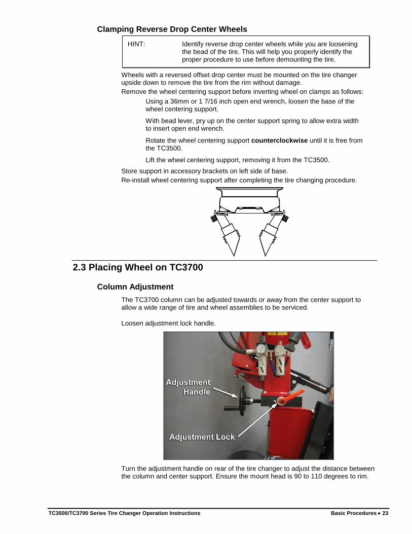
Column Adjustment
The TC3700 column can be adjusted towards or away from the center support to allow a wide range of tire and wheel assemblies to be serviced.
Loosen adjustment lock handle.
Turn the adjustment handle on rear of the tire changer to adjust the distance between the column and center support. Ensure the mount head is 90 to 110 degrees to rim.
24 Basic Procedures TC3500/TC3700 Series Tire Changer Operation Instructions
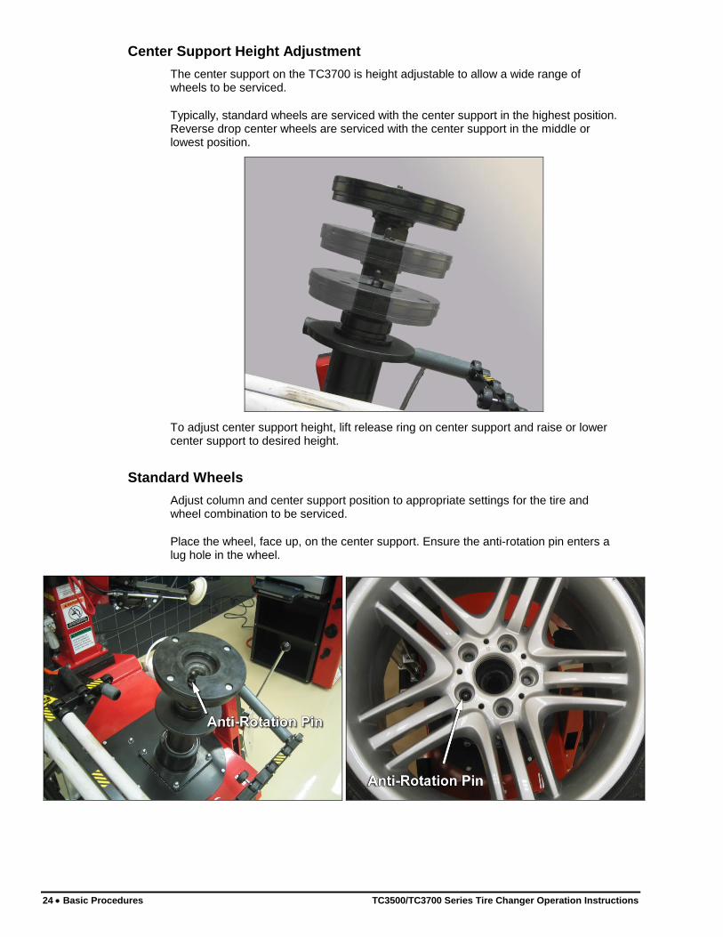
Center Support Height Adjustment
The center support on the TC3700 is height adjustable to allow a wide range of wheels to be serviced.
Typically, standard wheels are serviced with the center support in the highest position. Reverse drop center wheels are serviced with the center support in the middle or lowest position.
To adjust center support height, lift release ring on center support and raise or lower center support to desired height.
Standard Wheels
Adjust column and center support position to appropriate settings for the tire and wheel combination to be serviced.
Place the wheel, face up, on the center support. Ensure the anti-rotation pin enters a lug hole in the wheel.
TC3500/TC3700 Series Tire Changer Operation Instructions Basic Procedures 25
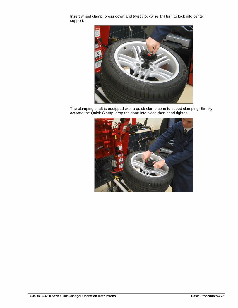
Insert wheel clamp, press down and twist clockwise 1/4 turn to lock into center support.
The clamping shaft is equipped with a quick clamp cone to speed clamping. Simply activate the Quick Clamp, drop the cone into place then hand tighten.

26 Basic Procedures TC3500/TC3700 Series Tire Changer Operation Instructions
Reverse Drop Center Wheels
Place anti-rotation pin protector and wheel protector pad on center support
Place wheel, face-down, on center support ensuring anti-rotation pin inserts one lug hole.
Insert wheel clamp, press down and twist clockwise 1/4 turn to lock into center support.
TC3500/TC3700 Series Tire Changer Operation Instructions Basic Procedures 27
The clamping shaft is equipped with a quick clamp cone to speed clamping. Simply activate the Quick Clamp, drop the cone into place then hand tighten.
2.4 Bead Loosening Standard Rim and Tire
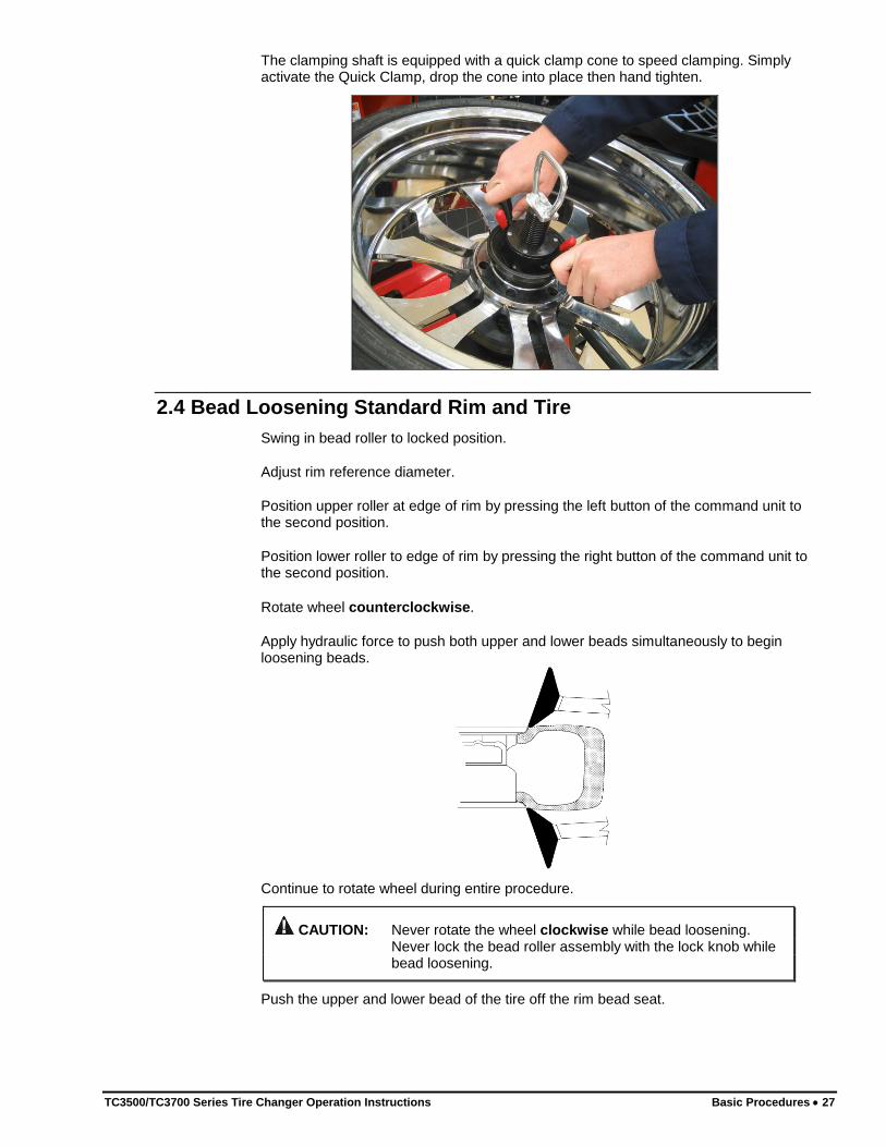
Swing in bead roller to locked position.
Adjust rim reference diameter.
Position upper roller at edge of rim by pressing the left button of the command unit to the second position.
Position lower roller to edge of rim by pressing the right button of the command unit to the second position.
Rotate wheel counterclockwise.
Apply hydraulic force to push both upper and lower beads simultaneously to begin loosening beads.
Continue to rotate wheel during entire procedure.
CAUTION: Never rotate the wheel clockwise while bead loosening. Never lock the bead roller assembly with the lock knob while bead loosening.
Push the upper and lower bead of the tire off the rim bead seat.
28 Basic Procedures TC3500/TC3700 Series Tire Changer Operation Instructions
CAUTION: Never place hands near the rollers while applying force and rotating tire. Hands could be pulled between the roller and tire causing injury.
Lubricate the lower bead and rim by inserting brush of lubricant into wheel just behind the roller.
Lubricate the upper bead and rim as above.
Retract rollers.
Swing the bead roller assembly away to the stored position.
For additional information on special wheels, refer to “Advanced Bead Loosening Procedures.”
2.5 Demounting Standard Tires from Rim
NOTE: For rims that have a clearcoat finish, clean the mount/demount head to remove dirt and debris before demounting the tire from the rim.
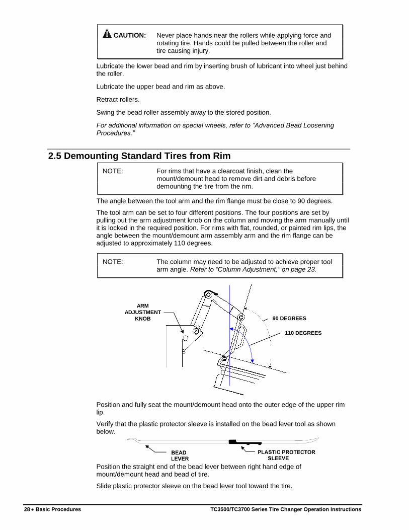
The angle between the tool arm and the rim flange must be close to 90 degrees.
The tool arm can be set to four different positions. The four positions are set by pulling out the arm adjustment knob on the column and moving the arm manually until it is locked in the required position. For rims with flat, rounded, or painted rim lips, the angle between the mount/demount arm assembly arm and the rim flange can be adjusted to approximately 110 degrees.
NOTE: The column may need to be adjusted to achieve proper tool arm angle. Refer to “Column Adjustment,” on page 23.
90 DEGREES
ARM
ADJUSTMENT
KNOB
110 DEGREES
Position and fully seat the mount/demount head onto the outer edge of the upper rim lip.
Verify that the plastic protector sleeve is installed on the bead lever tool as shown below.
Position the straight end of the bead lever between right hand edge of mount/demount head and bead of tire.
Slide plastic protector sleeve on the bead lever tool toward the tire.

TC3500/TC3700 Series Tire Changer Operation Instructions Basic Procedures 29
The mount/demount head should be positioned between the humps of the plastic protective sleeve.
Push down on the tire sidewall at the 6 o’clock position. On very stiff tires, use the Bead Depressor “Tail” to slip the sidewall into the drop center of the rim. Refer to “Using Bead Depressor “Tail” and Bottom Roller to Demount Upper Bead without Sleeve Protector.”
IMPORTANT: To prevent the plastic protective sleeve and mount/demount head from breaking during demounting, the mount/demount head must be fully seated on the outer edge of the upper rim lip before prying bead lever back for demounting.
Using the bead lever tool, lift the tire bead over the end of the head.
The bead lever tool must be pulled down parallel to the rim to prevent the possibility of breaking the plastic sleeve protector.
Rotate wheel clockwise until the entire bead is lifted from the rim.
Lift tire and repeat this procedure for lower bead.
HINT: If lower bead becomes re-seated on rim, push lower bead
roller up against lower bead while rotating counterclockwise to re-loosen.
Swing the mount/demount arm assembly up and away from the wheel.
Remove tire from rim.
For additional information on demounting special wheels, refer to “Advanced Mounting Procedures,” on page 44.
30 Basic Procedures TC3500/TC3700 Series Tire Changer Operation Instructions
2.6 Mounting Standard Tire to Rim
Always be aware of this “checklist” when mounting tires to ensure proper service.
There are four basic steps when mounting a tire to a rim:
Position the bead on top of the left lip of mount/demount head.
Position the bead under the right lip of the mount/demount head.
Lock the rim to the tire.
Slip the bead into the drop center.
These four basic steps to mounting do not necessarily follow the same sequence, however all four steps need to be performed to mount a tire to a rim.
Mount a standard tire to rim as follows:
Lubricate inside and outside of both beads of the tire to be mounted with supplied mounting paste.
Position tire on top of the rim and tilt tire forward toward column.
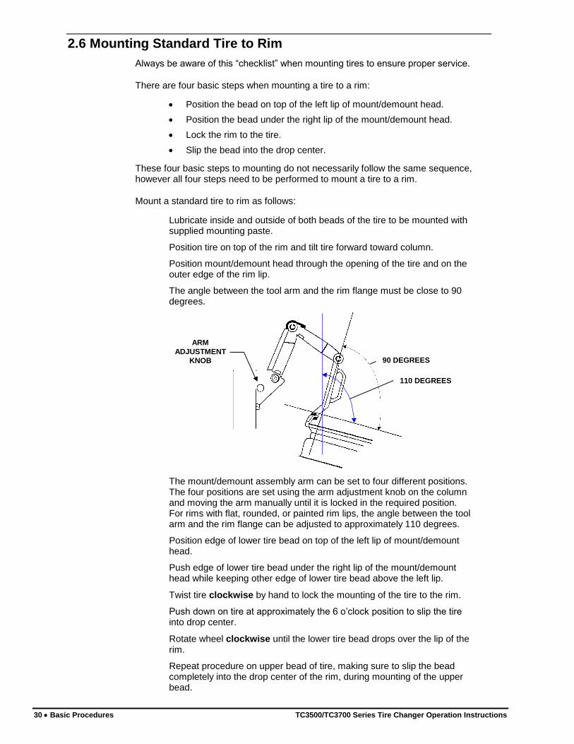
Position mount/demount head through the opening of the tire and on the outer edge of the rim lip.
The angle between the tool arm and the rim flange must be close to 90 degrees.
90 DEGREES
ARM
ADJUSTMENT
KNOB
110 DEGREES
The mount/demount assembly arm can be set to four different positions. The four positions are set using the arm adjustment knob on the column and moving the arm manually until it is locked in the required position. For rims with flat, rounded, or painted rim lips, the angle between the tool arm and the rim flange can be adjusted to approximately 110 degrees.
Position edge of lower tire bead on top of the left lip of mount/demount head.
Push edge of lower tire bead under the right lip of the mount/demount head while keeping other edge of lower tire bead above the left lip.
Twist tire clockwise by hand to lock the mounting of the tire to the rim.
Push down on tire at approximately the 6 o’clock position to slip the tire into drop center.
Rotate wheel clockwise until the lower tire bead drops over the lip of the rim.
Repeat procedure on upper bead of tire, making sure to slip the bead completely into the drop center of the rim, during mounting of the upper bead.

TC3500/TC3700 Series Tire Changer Operation Instructions Basic Procedures 31
NOTE: If the tire bead does not have sufficient lubrication and the tire fails to slip into drop center during mounting, the mount/demount head may fail before damage to tire bead takes place.
For additional information on special wheels, refer to “Advanced Mounting Procedures,” on page 44.
Precautionary Notes
When basic procedures are not followed, sharp angled wheel flanges increase potential damage to tires during mounting. Be sure the tire bead is placed on top of the mounting head. If the tire is incorrectly pushed onto the rim by the side of the mounting head, it may become “trapped” and increase mounting stress to the tire bead.
BEAD CORRECTLY PLACED ON TOP OF
MOUNTING HEAD
TIRE IS INCORRECTLY PUSHED ON BY
MOUNTING HEAD
Insufficient lubrication and failure to place tire into drop center during mounting may also cause the mount/demount head to fail prematurely.
2.7 Tire Inflation
Verify that the wheel has been properly clamped and centered.
WARNING: Never attempt to inflate a tire when the wheel is clamped
from the outside. Always reclamp the wheel from the
inside before inflating.
Remove the valve stem core from valve stem. Removing the valve stem core will allow the tire to inflate faster and the bead to seat easier.
Connect inflator hose to valve stem.
NOTE: To increase the effectiveness of inflation ring or blast inflation hose, always liberally lubricate the outer edge of the tire sidewall and pull up on the tire while twisting to seal the bead.
32 Basic Procedures TC3500/TC3700 Series Tire Changer Operation Instructions
TC3500 & TC3500-SS Models:
Step down completely on the air inflation pedal to release a high-pressure air blast through nozzles on the air inflation ring to assist in seating the beads of the tire.
Step down completely on the air inflation pedal to release a high-pressure air blast through the bead blast hose to assist in seating the beads of the tire.
Step down partially on the air inflation pedal to inflate tire and seat the beads.
WARNING: Do not exceed 40 PSI when seating the beads of a tire.
After beads have been seated, disconnect inflation hose and reinstall valve stem core previously removed. Then connect inflation hose and inflate tire to the required pressure.
If tire is over inflated, air may be removed from the tire by pressing the manual air release button located below the air pressure gauge.
Disconnect inflator hose from valve stem.
TC3510/TC3700 Models:
Verify that the wheel has been properly clamped and centered.
Remove the valve stem core from the valve stem. Removing the valve stem core will allow the bead to seat easier and the tire to inflate faster.
Connect inflator hose to valve stem.
NOTE: To increase the effectiveness of the air blast inflator, always liberally lubricate the outer edge of the tire sidewall and pull up on the tire, while twisting to seal the bead.
TC3500/TC3700 Series Tire Changer Operation Instructions Basic Procedures 33
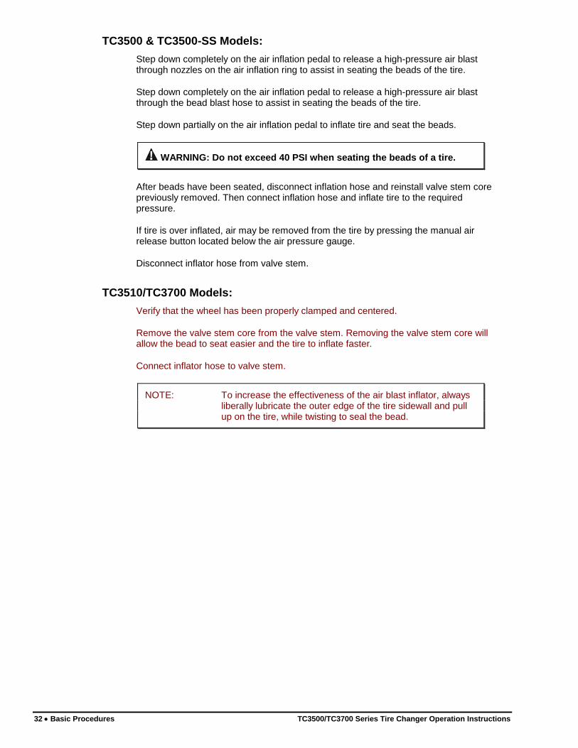
Press the bead blaster hose on the wheel rim as shown below. Ensure the hose head is pressed in.
NOTE: The nozzle should be horizontal for optimal performance.
CORRECT
INCORRECT
NOZZLE IS
HORIZONTAL
INCORRECT
NOZZLE IS NOT
HORIZONTAL
NOZZLE IS NOT
HORIZONTAL
Incorrect Correct
Step down completely on the air inflation pedal to release a high-pressure air blast through the bead blast hose to assist in seating the beads of the tire.
Step down partially on the air inflation pedal to inflate tire and seat the beads.
WARNING: Do not exceed 40 PSI when seating the beads of a tire.
After beads have been seated, disconnect inflation hose and reinstall valve stem core previously removed. Then connect inflation hose and inflate tire to the required pressure.
34 Basic Procedures TC3500/TC3700 Series Tire Changer Operation Instructions
If tire is over inflated, air may be removed from the tire by pressing the manual air release button located below the air pressure gauge.
Disconnect inflator hose from valve stem.
2.8 Removal of Wheel from TC3500-SS/TC3700
Remove wheel-securing device, if installed.
For rims clamped on inside, lift the clamping pedal to release the rim from the clamping device.
For rims clamped on outside, step down on the clamping pedal to release the rim from the clamping device.
2.9 Removal of Wheel from TC3700
Loosen clamping cone.
Press down and turn counter-clockwise to unlock clamp from center support. Remove wheel clamp.
Remove wheel from center support.
If applicable, remove anti-rotation pin protector and wheel protector pad from center support.

TC3500/TC3700 Series Tire Changer Operation Instructions Advanced Procedures 35
3. ADVANCED PROCEDURES
The capabilities of the TC3500 and TC3700 series tire changers allow the user to utilize numerous advanced procedures on a variety of rims and tires. For the operator to take advantage of these features, this section explains in detail what additional steps can be taken.
3.1 Advanced Bead Loosening Procedures
Bead Loosening Soft Sidewall, Tall Profile Tires
Swing the bead roller assembly in toward the column to the working position (against the stop).
Set rim diameter.
WARNING: Never place hands near the rollers while applying force
and rotating wheel.
Bring the upper bead roller down until it contacts the tire at the edge of the rim.
Lock upper roller into the side of the tire.
Bring the lower bead roller up until it contacts the tire.
Lock the lower roller into the side of the tire.
Continue to rotate wheel during the entire loosening procedure.
CAUTION: Never rotate the wheel clockwise while bead loosening. Never lock the bead roller assembly with the lock knob while bead loosening.
Leaving no more than 5 psi in the tire may help to stiffen the sidewall and loosen the bead.
Use multiple rotations to loosen the bead, while slowly increasing roller pressure. Let the roller work the bead.
Push the lower bead of the tire off the rim bead seat while rotating tire.
Fully lubricate the lower bead and rim by inserting brush with lubricant into rim, just behind the roller.
Retract lower roller.
Push the upper bead of the tire off the rim bead seat while rotating tire.
Lubricate upper bead, rim bead seat, rim balcony, and drop center.
Retract upper roller.
Swing the bead roller assembly away to the resting position.

36 Advanced Procedures TC3500/TC3700 Series Tire Changer Operation Instructions
Bead Loosening Tough, Low Profile Tires
Swing the bead roller assembly in toward the column to the working position (against the stop).
Set rim diameter.
WARNING: Never place hands near the rollers while applying force
and rotating wheel.
Bring the upper bead roller down until it contacts the tire at the edge of the rim.
Lock upper roller into the side of the tire by pushing the upper roller down while
rotating wheel counterclockwise so it is approximately 1/4 inch below rim edge.
Bring the lower bead roller up until it contacts the tire.
Lock the lower roller into the side of the tire.
Continue to rotate wheel during the entire loosening procedure.
CAUTION: Never rotate the wheel clockwise while bead loosening. Never lock the bead roller assembly with the lock knob while bead loosening.
Push the lower bead of the tire off the rim bead seat while rotating tire.
Fully lubricate the lower bead and rim by inserting brush with lubricant into rim, just behind the roller.
Retract lower roller.
Push the upper bead of the tire off the rim bead seat while rotating tire.
Lubricate upper bead, rim bead seat, rim balcony, and drop center.
Retract upper roller.
Swing the bead roller assembly away to the resting position.
Bead Loosening “AH” Wheels
NOTE: The following illustrations show a TC3500 series tire changer. The procedures are similar on a TC3700, only the wheel clamping differs. Refer to appropriate sections for specific clamping instructions.
(e.g. BMW M3, M5, some Porsche, Range Rover, Lancia, etc.)
“AH” wheels may be identified by looking on the rim for an “AH” code cast in the rim size designation (e.g. 71/2J X17AH2.) Refer to “Illustration of AH2 Rim (Asymmetrical Humps) “Bead Locking System.”
TC3500/TC3700 Series Tire Changer Operation Instructions Advanced Procedures 37
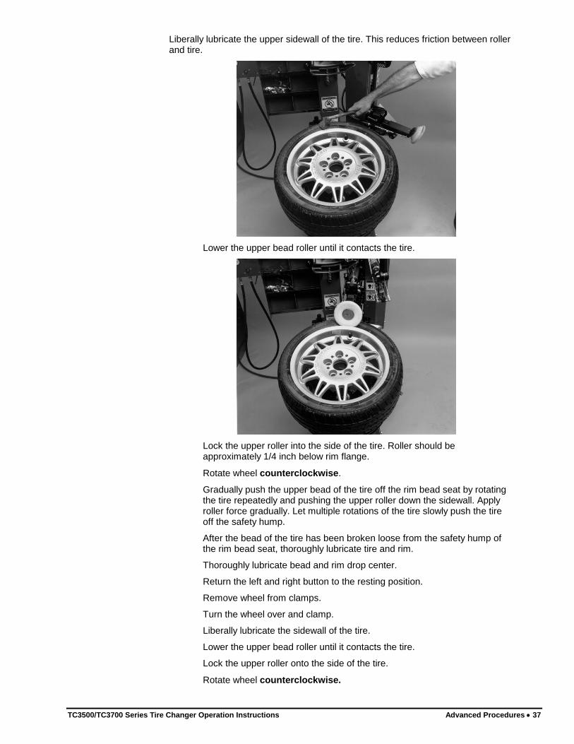
Liberally lubricate the upper sidewall of the tire. This reduces friction between roller and tire.
Lower the upper bead roller until it contacts the tire.
Lock the upper roller into the side of the tire. Roller should be approximately 1/4 inch below rim flange.
Rotate wheel counterclockwise.
Gradually push the upper bead of the tire off the rim bead seat by rotating the tire repeatedly and pushing the upper roller down the sidewall. Apply roller force gradually. Let multiple rotations of the tire slowly push the tire off the safety hump.
After the bead of the tire has been broken loose from the safety hump of the rim bead seat, thoroughly lubricate tire and rim.
Thoroughly lubricate bead and rim drop center.
Return the left and right button to the resting position.
Remove wheel from clamps.
Turn the wheel over and clamp.
Liberally lubricate the sidewall of the tire.
Lower the upper bead roller until it contacts the tire.
Lock the upper roller onto the side of the tire.
Rotate wheel counterclockwise.
38 Advanced Procedures TC3500/TC3700 Series Tire Changer Operation Instructions
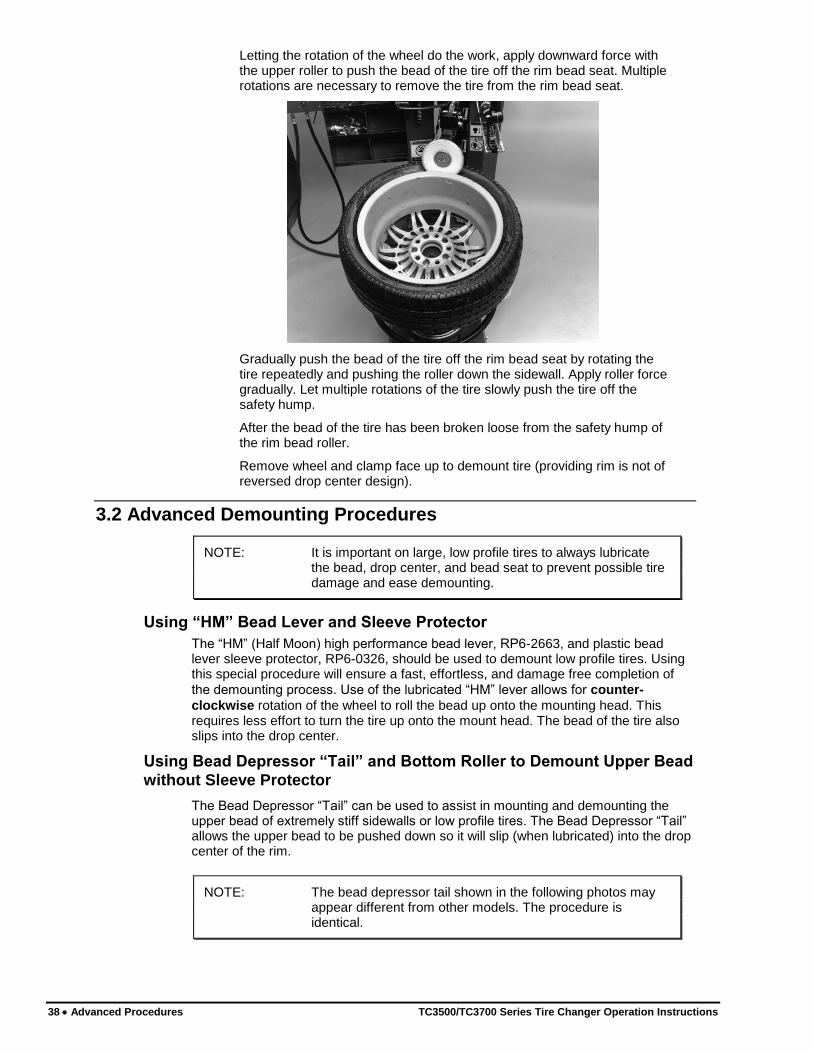
Letting the rotation of the wheel do the work, apply downward force with the upper roller to push the bead of the tire off the rim bead seat. Multiple rotations are necessary to remove the tire from the rim bead seat.
Gradually push the bead of the tire off the rim bead seat by rotating the tire repeatedly and pushing the roller down the sidewall. Apply roller force gradually. Let multiple rotations of the tire slowly push the tire off the safety hump.
After the bead of the tire has been broken loose from the safety hump of the rim bead roller.
Remove wheel and clamp face up to demount tire (providing rim is not of reversed drop center design).
3.2 Advanced Demounting Procedures
NOTE: It is important on large, low profile tires to always lubricate the bead, drop center, and bead seat to prevent possible tire damage and ease demounting.
Using “HM” Bead Lever and Sleeve Protector
The “HM” (Half Moon) high performance bead lever, RP6-2663, and plastic bead lever sleeve protector, RP6-0326, should be used to demount low profile tires. Using this special procedure will ensure a fast, effortless, and damage free completion of
the demounting process. Use of the lubricated “HM” lever allows for counter-
clockwise rotation of the wheel to roll the bead up onto the mounting head. This requires less effort to turn the tire up onto the mount head. The bead of the tire also slips into the drop center.
Using Bead Depressor “Tail” and Bottom Roller to Demount Upper Bead
without Sleeve Protector
The Bead Depressor “Tail” can be used to assist in mounting and demounting the upper bead of extremely stiff sidewalls or low profile tires. The Bead Depressor “Tail” allows the upper bead to be pushed down so it will slip (when lubricated) into the drop center of the rim.
NOTE: The bead depressor tail shown in the following photos may appear different from other models. The procedure is identical.

TC3500/TC3700 Series Tire Changer Operation Instructions Advanced Procedures 39
Demounting:
Swing the bead roller assembly in toward the unit to the working position (against the stop). Lock pin into this position.
Lubricate the upper bead and the entrance of the drop center, while rotating the wheel
counterclockwise and using the upper bead roller to push down on the bead.
Lock the bead roller fixation knob.
Rotate the wheel clockwise until the valve stem is at the 1 o'clock position.
Lubricate and push the bead depressor post through the center hole of the rim until it has been inserted into the spring centering system.
HINT: If the post will not insert into the center hole, the wheel support is depressed too far down. Release the clamping jaws and reposition the arms to allow for less compression of the support and try again.
Push the sidewall down with upper roller to allow the insertion of the block on the arm.

40 Advanced Procedures TC3500/TC3700 Series Tire Changer Operation Instructions
Slide the horizontal arm of the tail so the fixed block is positioned into the rim flange as shown below.
Rotate wheel clockwise and position each of the attached blocks of the bead depressor onto the rim as shown. Each block should be positioned as far away from the next block as the cord will allow.
For rims that have an extra deep drop center, position each of the following attached blocks under the rim lip as shown below.
Rotate the wheel clockwise until the Bead Depressor “Tail” is installed between the 3 o'clock and 9 o'clock positions.
Position mount/demount arm assembly onto the outer edge of the upper rim lip.
Liberally lubricate bead lever tool on both top and bottom.

TC3500/TC3700 Series Tire Changer Operation Instructions Advanced Procedures 41
Use the upper roller to aid in the lever insertion, if necessary. Position bead lever tool between right-hand edge of mount/demount head and the bead of the tire.
Pull back on bead lever tool repeatedly to force tire forward, and slip the backside of the depressed “Tail” area into the drop center.
Position bottom roller and push on the lower bead of the tire.
NOTE: The mount/demount head must be fully seated on the outer edge of the upper rim lip before prying bead lever back for demounting.
Partially lift the tire bead over the right-hand end of the head.
Push bottom roller up again to fully bring tire bead over head.
Rotate the wheel counterclockwise approximately 1/2 inch to unfurl tire bead onto the bead lever.
Slide the bead lever tool out from between the mount/demount head and the bead of the tire. The bead of the tire must remain over the right-hand end of the head.
Rotate wheel clockwise until the entire bead is lifted from the rim. Remove the Bead Depressor “Tail” from the rim while rotating. Refer to “Removal of Bead Depressor Tail,” on page 47.
Retract the lower roller to the resting position.
42 Advanced Procedures TC3500/TC3700 Series Tire Changer Operation Instructions
Using Force Multiplier, RP6-G1000A23 (Optional on TC3510)
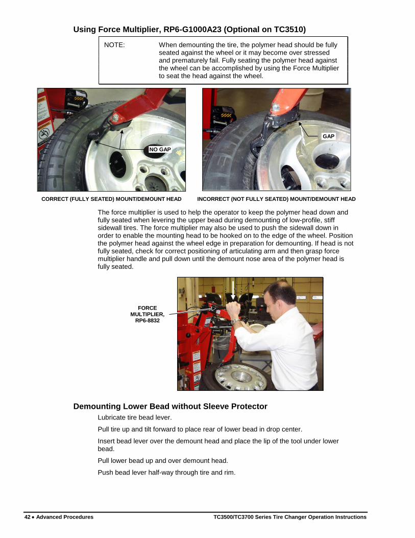
NOTE: When demounting the tire, the polymer head should be fully seated against the wheel or it may become over stressed and prematurely fail. Fully seating the polymer head against the wheel can be accomplished by using the Force Multiplier to seat the head against the wheel.
NO GAP
GAP
CORRECT (FULLY SEATED) MOUNT/DEMOUNT HEAD INCORRECT (NOT FULLY SEATED) MOUNT/DEMOUNT HEAD
The force multiplier is used to help the operator to keep the polymer head down and fully seated when levering the upper bead during demounting of low-profile, stiff sidewall tires. The force multiplier may also be used to push the sidewall down in order to enable the mounting head to be hooked on to the edge of the wheel. Position the polymer head against the wheel edge in preparation for demounting. If head is not fully seated, check for correct positioning of articulating arm and then grasp force multiplier handle and pull down until the demount nose area of the polymer head is fully seated.
FORCE MULTIPLIER,
RP6-8832
Demounting Lower Bead without Sleeve Protector
Lubricate tire bead lever.
Pull tire up and tilt forward to place rear of lower bead in drop center.
Insert bead lever over the demount head and place the lip of the tool under lower bead.
Pull lower bead up and over demount head.
Push bead lever half-way through tire and rim.
TC3500/TC3700 Series Tire Changer Operation Instructions Advanced Procedures 43
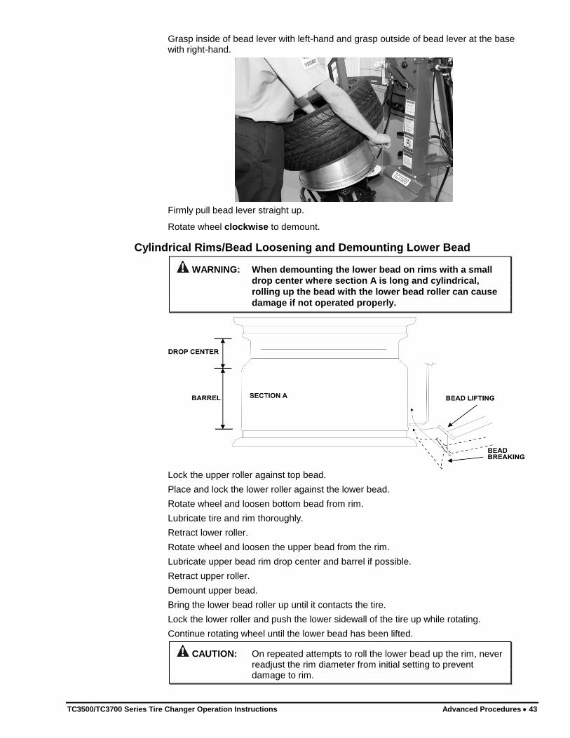
Grasp inside of bead lever with left-hand and grasp outside of bead lever at the base with right-hand.
Firmly pull bead lever straight up.
Rotate wheel clockwise to demount.
Cylindrical Rims/Bead Loosening and Demounting Lower Bead
WARNING: When demounting the lower bead on rims with a small
drop center where section A is long and cylindrical,
rolling up the bead with the lower bead roller can cause
damage if not operated properly.
Lock the upper roller against top bead.
Place and lock the lower roller against the lower bead.
Rotate wheel and loosen bottom bead from rim.
Lubricate tire and rim thoroughly.
Retract lower roller.
Rotate wheel and loosen the upper bead from the rim.
Lubricate upper bead rim drop center and barrel if possible.
Retract upper roller.
Demount upper bead.
Bring the lower bead roller up until it contacts the tire.
Lock the lower roller and push the lower sidewall of the tire up while rotating.
Continue rotating wheel until the lower bead has been lifted.
CAUTION: On repeated attempts to roll the lower bead up the rim, never readjust the rim diameter from initial setting to prevent damage to rim.

44 Advanced Procedures TC3500/TC3700 Series Tire Changer Operation Instructions
3.3 Advanced Mounting Procedures
Always be aware of this “checklist” when mounting tires to ensure proper service.
There are four steps when mounting a tire to a rim:
Position the bead on top of the left lip of mount/demount head.
Position the bead under the right lip of the mount/demount head.
Lock the rim to the tire.
Slip the bead into the drop center.
These four basic steps to mounting do not necessarily follow the same sequence, however all four steps need to be performed to properly mount a tire to a rim.
Mechanical Bead Pusher, RP6-2413
The Mechanical Bead Pusher is used for pushing the upper bead below the right hand area of the mount head, keeping the tire in the proper location during mounting of stiff, low profile tires.
To use:
Mount the bottom bead of the tire onto the wheel. Position the upper bead of the tire on the upper left side of the mounting head. Rotate and lock the mechanical bead pusher into the "IN USE" position with the tire sidewall passing below the locked mechanical bead pusher roller. The locked roller of the bead pusher will keep the tire bead and sidewall below the right side of the mounting head.
To store:
Unlock and rotate the mechanical bead pusher into the “STORED” position.
TC3500/TC3700 Series Tire Changer Operation Instructions Advanced Procedures 45
Mounting of Stiff Sidewall, Low Profile Tires
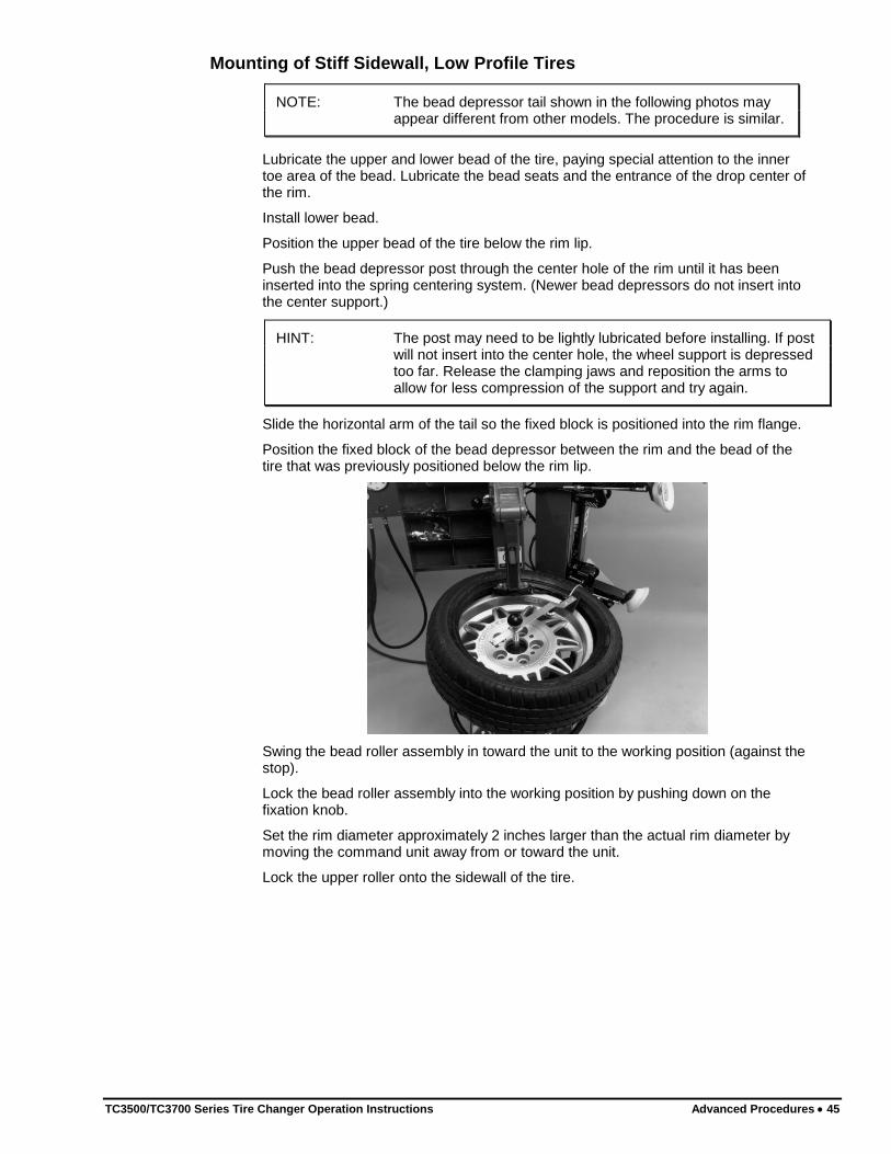
NOTE: The bead depressor tail shown in the following photos may appear different from other models. The procedure is similar.
Lubricate the upper and lower bead of the tire, paying special attention to the inner toe area of the bead. Lubricate the bead seats and the entrance of the drop center of the rim.
Install lower bead.
Position the upper bead of the tire below the rim lip.
Push the bead depressor post through the center hole of the rim until it has been inserted into the spring centering system. (Newer bead depressors do not insert into the center support.)
HINT: The post may need to be lightly lubricated before installing. If post will not insert into the center hole, the wheel support is depressed too far. Release the clamping jaws and reposition the arms to allow for less compression of the support and try again.
Slide the horizontal arm of the tail so the fixed block is positioned into the rim flange.
Position the fixed block of the bead depressor between the rim and the bead of the tire that was previously positioned below the rim lip.
Swing the bead roller assembly in toward the unit to the working position (against the stop).
Lock the bead roller assembly into the working position by pushing down on the fixation knob.
Set the rim diameter approximately 2 inches larger than the actual rim diameter by moving the command unit away from or toward the unit.
Lock the upper roller onto the sidewall of the tire.

46 Advanced Procedures TC3500/TC3700 Series Tire Changer Operation Instructions
Position the bead of the tire under the right side of the mount head.
Rotate the wheel clockwise and position each of the attached blocks of the bead depressor onto the rim as shown below. Each block should be positioned as far away from the next block as the cord will allow.
Rotate the wheel clockwise until the upper bead of the tire is completely installed. To prevent rim from spinning inside the tire, grasp tire at location shown below and pull tire along with rim during rotation.
Remove Bead Depressor “Tail” from rim.
TC3500/TC3700 Series Tire Changer Operation Instructions Advanced Procedures 47
Removal of Bead Depressor “Tail”
CAUTION: Never forcefully pull bead depressor “tail” out of tire after installation to avoid damage to tool and/or rim.
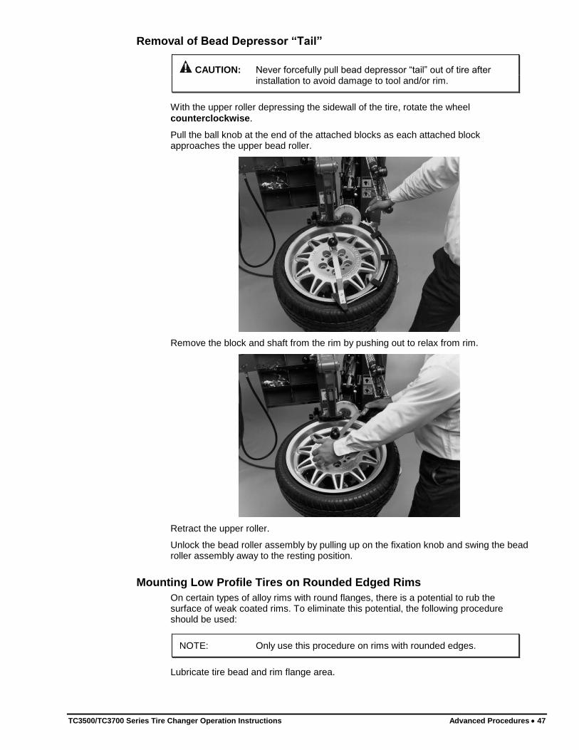
With the upper roller depressing the sidewall of the tire, rotate the wheel
counterclockwise.
Pull the ball knob at the end of the attached blocks as each attached block approaches the upper bead roller.
Remove the block and shaft from the rim by pushing out to relax from rim.
Retract the upper roller.
Unlock the bead roller assembly by pulling up on the fixation knob and swing the bead roller assembly away to the resting position.
Mounting Low Profile Tires on Rounded Edged Rims
On certain types of alloy rims with round flanges, there is a potential to rub the surface of weak coated rims. To eliminate this potential, the following procedure should be used:
NOTE: Only use this procedure on rims with rounded edges.
Lubricate tire bead and rim flange area.

48 Advanced Procedures TC3500/TC3700 Series Tire Changer Operation Instructions
Adjust articulating arm back to the #4 position.
Push upper roller down against tire to ensure the mounting head is secured by the upper roller. This will prevent the mounting head from popping up when the tire is fully mounted.
Push on the bead while rotating wheel clockwise instead of going over the top of the mounting head.
Lock the rim to the tire by hand, or by using the bead lever or bead depressor “tail.”
Slip the bead into the drop center.
Rotate wheel clockwise to mount tire.
3.4 Mounting Stiff, Low Profile Tires on Rounded Edged Rims Only
Using Rollers
CAUTION: This special case procedure does not perform properly on all tires. Tires of the same size, but of different makes react differently to this method. Attempt first tire slowly to determine compatibility of this procedure with application.
Mount lower bead as normal.
Move roller assembly into work position.
Lower the upper roller against the upper bead approximately 1/2 inch away from the rim edge.
Grasp and support tire at the 6 o’clock position.

TC3500/TC3700 Series Tire Changer Operation Instructions Advanced Procedures 49
Lower the upper roller and push bead down slightly so it is below the balcony of the drop center.
Lock the tire to the rim by grasping the tire with a cross-handed grip.
Rotate the wheel counterclockwise and press down hard on the tire at the 6 o’clock position to guide tire into the drop center.
Continue mounting by rotating the wheel counterclockwise until upper bead is mounted.
Retract upper roller and swing bead roller assembly away to prepare for inflation.
HINT: Use of bead depressor (without inserting tail) may assist in locking tire to rim during mounting.

50 Advanced Procedures TC3500/TC3700 Series Tire Changer Operation Instructions
3.5 Matching/Optimizing of Tire to Rim
Matching/Optimizing allows positioning of the rim to the tire for proper mounting to minimize vibrations. This procedure must be done with both beads fully loosened and well lubricated.
Match/Optimize the rim to the tire as follows:
Set the rim diameter approximately 1 to 2 inches larger than the actual rim diameter.
Bring the lower bead roller up until it contacts the tire.
Bring the upper bead roller down until it contacts the tire.
Rotate wheel counterclockwise and continue rotating for next three steps.
Lock upper roller and push in on sidewall of the tire until upper bead is in drop center of rim.
Lock lower roller and push in on sidewall of the tire until rim and tire are rotating at two different speeds.
NOTE: For reverse drop center rims, reverse the previous two procedures:
Lock lower roller and push in on sidewall of tire until bead is in drop center.
Lock upper roller and push in on sidewall of tire until rim and tire are rotating at two different speeds.
Continue rotating the tire and rim at different speeds until the rim spins inside the tire and the mark on the tire is positioned where needed in reference to the rim.
Once matching has occurred, retract arms and inflate.
3.6 Optional Steel Mount/Demount Head Assembly (RP6-2654)
Use standard procedures for mounting and demounting.
The optional steel mount/demount head assembly is to be used for mounting or
demounting tires from steel rims only. DO NOT use the steel mount/demount head assembly on alloy rims, it could damage the finish.

TC3500/TC3700 Series Tire Changer Operation Instructions Maintenance and Calibration 51
4. MAINTENANCE AND
CALIBRATION
CAUTION: Do not hose down or power wash electric tire changers.
4.1 Maintenance Schedule
Proper care and maintenance are necessary to ensure that the tire changer operates properly. Proper care will also ensure that rims and tires are not damaged during the mount/demount process.
Maintenance Schedule Perform the Following Maintenance
Daily Drain condensation from pressure regulator reservoir by pressing in on the fitting located on the bottom of the regulator.
Check for worn or damaged rubber and nylon components that should be replaced to prevent damage from occurring. Replace worn parts as needed (rubber pads and blocks, claw protectors, lever protector sleeve and mount/demount head).
Check proper operation of tire inflation safety limiter.
Clean all areas that contact rims or tires to prevent possible scratching to rim.
Weekly Clean the tire changer with shop towels or a vacuum
cleaner. Do not clean with or use compressed air,
which can blast dirt between moving parts. Do not use cleaning solvents to clean pressure regulator/oiler.
Periodically Refill the pressure regulator/oiler using only Hunter
Lubri-oil as needed. Petroleum-based oils should
never be used in the oiler and may void all
warranties.
Adjust the screw on top of the column mounted oiler to release one drop of oil every four revolutions. Adjust bead roller mounted oiler to release one drop of oil for every seven complete arm positioning strokes.
Lubricate oil fittings as shown on decal on side of storage tray.
Check for loose bolts and tighten per specifications.
52 Maintenance and Calibration TC3500/TC3700 Series Tire Changer Operation Instructions
4.2 Maintenance Replacement Parts QTY NAME NUMBER
1 Safety Goggles 179-15-2
1 Brush RP6-1506
1 Mounting Paste RP6-3784
1 Steel Jaw Cover (Set Of 4) RP6-2252
1 Mount/Demount Head 221-675-2
1 “HM” Bead Lever RP6-G1000A11
1 Bead Lever Protector Sleeve RP6-0326
1 Rubber Bonded External Clamping Jaw RP6-8659
4.3 Calibrating and Adjusting the Position of the Column
Check the column position as follows:
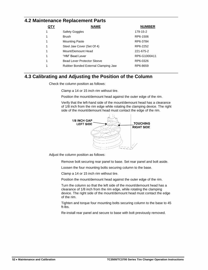
Clamp a 14 or 15 inch rim without tire.
Position the mount/demount head against the outer edge of the rim.
Verify that the left-hand side of the mount/demount head has a clearance of 1/8 inch from the rim edge while rotating the clamping device. The right side of the mount/demount head must contact the edge of the rim.
Adjust the column position as follows:
Remove bolt securing rear panel to base. Set rear panel and bolt aside.
Loosen the four mounting bolts securing column to the base.
Clamp a 14 or 15 inch rim without tire.
Position the mount/demount head against the outer edge of the rim.
Turn the column so that the left side of the mount/demount head has a clearance of 1/8 inch from the rim edge, while rotating the clamping device. The right side of the mount/demount head must contact the edge of the rim.
Tighten and torque four mounting bolts securing column to the base to 45 ft-lbs.
Re-install rear panel and secure to base with bolt previously removed.

TC3500/TC3700 Series Tire Changer Operation Instructions Maintenance and Calibration 53
4.4 Checking and Adjusting the Bead Rollers
Check to ensure bead rollers operate in line with each other as follows:
Position the bead roller assembly into its working position.
Clamp a 14 or 15 inch rim without tire, from the outside of the rim with rubber jaws.
Set the rim diameter indicator to the diameter of the mounted rim.
Rotate the wheel so that the lower roller arm will not contact the tulip arm.
Lower the upper bead arm so the roller just passes the outboard flange of the rim by 1/8 of an inch.
Return the upper arm to the resting position.
Raise the lower arm and note if there is any difference in distance when the roller is passing the lower rim edge. The lower bead roller should pass the inboard flange of the rim at same position as the upper roller setting.
Adjust rollers as follows:
Loosen both nuts that lock the lower bead roller arm adjustment cable.
Pull or push the cable until the lower roller is passing the inboard flange at the same distance as the upper roller.
Tighten both nuts to lock the lower bead roller arm adjustment cable.
Move the bead roller command handle a couple of times forward and backward.
Verify that the bead rollers operate in line with each other and adjust as needed.
4.5 Checking and Adjusting the Position of the Bead Breaker Arm
Verify that the position of the bead breaker arm is slightly to the right of the centerline of the wheel.
If bead breaker arm needs to be repositioned, loosen the two stop bolts of the roller assembly and position as needed.


TC3500/TC3700 Series Tire Changer Operation Instructions Glossary 55
5. GLOSSARY
5.1 Rim Diagram

56 Glossary TC3500/TC3700 Series Tire Changer Operation Instructions
5.2 Illustration of AH2 Rim (Asymmetrical Humps)
“Bead Locking System”
TC3500/TC3700 Series Tire Changer Operation Instructions Glossary 57
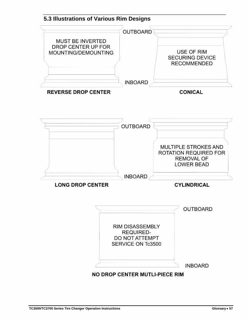
5.3 Illustrations of Various Rim Designs