Tbs Discovery Manual
30
TBS DISCOVERY Quadrotor Durable and crash resistant multirotor optimized for dynamic FPV flight Revision 2013-08-12 The TBS DISCOVERY quadcopter is a durable and crash resistant multirotor optimized for dynamic FPV flight. By implementing the wiring into the frame, the copter is easy to build and outperforms similar quads in terms of FPV range and video link quality. It is perfect for all looking at a durable and highly integrated FPV solution. The DJI Flame Wheel arms as predetermined breaking point protect your electronics and are easily replaceable in the field. The TBS DISCOVERY comes as two main boards (top and bottom) and optional Flame Wheel arms with accessories. It transforms the popular F450 (Flame Wheel) into a spider quadrotor. The GoPro and FPV camera mount is placed ideally for "no-prop-in-view" pictures. The optional TBS CORE can be placed directly onto the frame or we can install it for you. Features ● TBS CORE pre-wired incl. sockets for Plug&Play VTx and FPV camera installation ● 50A Current Sensor installed on the board, built for the TBS CORE or similar OSDs ● GoPro and FPV camera mounts ● Power Distribution Board (PDB) ● Traces and pads for clean R/C receiver to Flight Controller wiring ● RSSI trace to the TBS CORE 1
-
Upload
fiemsabyasachi -
Category
Documents
-
view
145 -
download
2
Transcript of Tbs Discovery Manual

TBS DISCOVERY QuadrotorDurable and crash resistant multirotor optimized fordynamic FPV flight
Revision 2013-08-12
The TBS DISCOVERY quadcopter is a durable and crash resistant
multirotor optimized for dynamic FPV flight. By implementing the wiring
into the frame, the copter is easy to build and outperforms similar quads in
terms of FPV range and video link quality. It is perfect for all looking at a
durable and highly integrated FPV solution. The DJI Flame Wheel arms as
predetermined breaking point protect your electronics and are easily replaceable in the field.
The TBS DISCOVERY comes as two main boards (top and bottom) and optional Flame Wheel arms with
accessories. It transforms the popular F450 (Flame Wheel) into a spider quadrotor. The GoPro and FPV
camera mount is placed ideally for "no-prop-in-view" pictures. The optional TBS CORE can be placed
directly onto the frame or we can install it for you.
Features
● TBS CORE pre-wired incl. sockets for Plug&Play VTx and FPV camera installation
● 50A Current Sensor installed on the board, built for the TBS CORE or similar OSDs
● GoPro and FPV camera mounts
● Power Distribution Board (PDB)
● Traces and pads for clean R/C receiver to Flight Controller wiring
● RSSI trace to the TBS CORE
1

Before we begin
Thank you for buying a TBS product! The TBS DISCOVERY is a new multirotor aircraft from Team
BlackSheep (TBS) and features the best design practices available on the market to date, providing great
flying stability and incredible FPV characteristics.
Please read this manual carefully before assembling and flying your new TBS DISCOVERY quadrotor.
Keep this manual for future reference regarding tuning and maintenance.
Disclaimer
Our request to you; the aircraft may not be used to infringe on people's right to privacy. We have
designed a toy with mind blowing capabilities. It is your responsibility to use it reasonably and
according to your experience level. Use common sense. Fly safe. You are on your own. TBS has no
liability for use of this aircraft.
● Locate an appropriate flying location
● Obtain the assistance of an experienced pilot
● Practice safe and responsible operation
● Always be aware of the rotating blades
● Prevent moisture
● Keep away from heat or excessive amounts of sunlight
2

Specifications
Type: Asymmetric spider quadrotor
Airframe: Reinforced black fiberglass (top RF transparent, bottom PDB)
Battery: 3S (11.1V) 5000 to 6000mAh or 4S (14.8V) 2500 to 4500mAh LiPo pack
Propellers: 9x5-inch or 10x5-inch (2xCW, 2xCCW)
Motor: 2212 or 2216 class, 700-900kV, 150-220W, 16x19 mm mount pattern
Speed controllers: 18 to 30A 400Hz Multirotor ESCs
Receiver: 5 channels or more
Flight controller: Standard quadcopter controller with optional GPS module
Current sensor (on-board): v1.1 100A, v1.2 and later 50A
Center of Gravity: 15mm in front of Center of Thrust mark
Duration: 8 to 15min (dependent on drive train and battery system)
Distance: up to 5km range (and return)
Altitude: up to 2km / 6000ft
All-up-weight: 1400 to 2000g
Required tools
● Hex screwdrivers (M2.5 and M3)
● Soldering iron (50 to 100W recommended)
● Solder (multicore flux)
● Propeller balancer (recommended)
3

Parts list
Before building your TBS DISCOVERY, make sure the following items are included in your kit.
1x Top frame plate 1x Bottom frame plate 1x Pilot camera mount plate
8x Red aluminum spacers 32x M3x6mm hex fitting screwsfor spacers and motors
24x M2.5x4mm hex frame armscrews
2x Pin headers for R/C (3x8rows, 2.54mm pitch)
2x Pin header rows for TBSCORE (2mm pitch)
2x VTx and camera picoblademolex cables
Required parts
To get in the air the following equipment and parts are needed for assembly.
4x DJI Flame Wheel arms 4x 400Hz Multirotor SpeedController 18-30A
4x 750 to 900kV brushlessmotors (incl. prop adaptor andmounting screws)
4
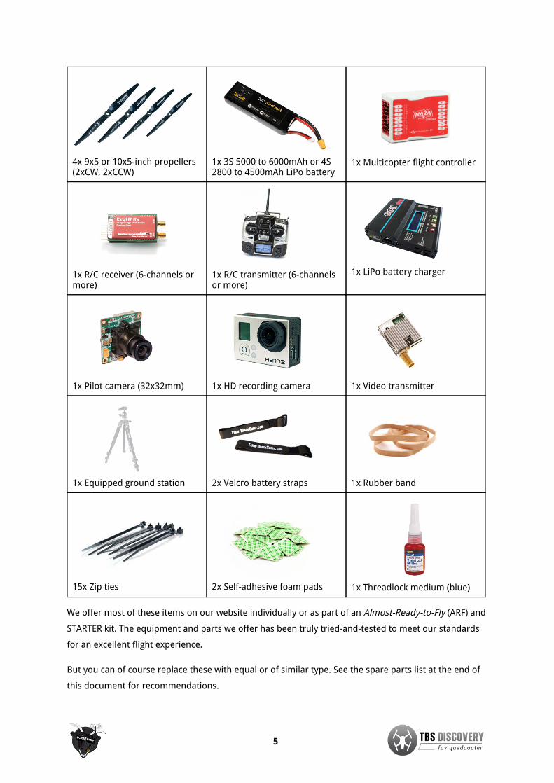
4x 9x5 or 10x5-inch propellers(2xCW, 2xCCW)
1x 3S 5000 to 6000mAh or 4S2800 to 4500mAh LiPo battery
1x Multicopter flight controller
1x R/C receiver (6-channels ormore)
1x R/C transmitter (6-channelsor more)
1x LiPo battery charger
1x Pilot camera (32x32mm) 1x HD recording camera 1x Video transmitter
1x Equipped ground station 2x Velcro battery straps 1x Rubber band
15x Zip ties 2x Self-adhesive foam pads 1x Threadlock medium (blue)
We offer most of these items on our website individually or as part of an Almost-Ready-to-Fly (ARF) and
STARTER kit. The equipment and parts we offer has been truly tried-and-tested to meet our standards
for an excellent flight experience.
But you can of course replace these with equal or of similar type. See the spare parts list at the end of
this document for recommendations.
5

Frequency choice
Frequency choice depends on the ranges you want to fly. Using 5.8GHz video is an ideal frequency if
you don't plan on flying far away from yourself or behind objects. It is compatible with 2.4GHz remote
controls.
Using 2.4GHz video (TBS video frequency of choice) will give you nearly unlimited range and far
superior link quality, but you can not use your 2.4GHz remote control on the same quad because of
limited separation (it is no problem for our R/C buddies to fly with 2.4GHz remote controls next to you
though!). You will need an EzUHF or any other UHF control system available on the market.
1.2GHz works very well in urban environments where the 2.4GHz band is completely polluted.
By using the same connector type across all transmission frequencies, the TBS eco-system allows quick
and effortless switching between the frequencies.
Typical ranges (based on customer feedback) with omnidirectional antennas:
● Lawmate 2.4GHz 500mW - 4km
● TBS 5.8GHz 25mW - 400m
● TBS 5.8GHz 200mW - 1.4km
● Boscam/Foxtech/HobbyKing 5.8GHz 500mW - do NOT buy, bad design!
● Boscam/Foxtech/HobbyKing 5.8GHz 400mW - 2.5km
● ImmersionRC 5.8GHz 600mW - 1.5km
More range can be achieved by using higher gain (directional) antennas. With the 11dBi TBS Yagi on
500mW Lawmate 2.4GHz gear, 10km of range is no problem at all. The battery normally only lasts for
8km of flight (4km and return.)
6

Choosing the right setup
If you are just getting into the hobby and you have absolutely nothing, consider the following
components to buy. Use these suggested setups as a “shopping list” if you are just getting started. Any
existing gear you already own (e.g. remote controls, chargers, batteries) can be used with the TBS
DISCOVERY.
These setups, with the exception of the Camera Tripod and the Remote Control, are available from
Team BlackSheep. Remote controls can be purchased at your local hobby shop, camera tripods are
available from big electronics wholesalers or Ebay.
TBS DISCOVERY setup for short range flights
● Expected flight time: 8-12 min
● Approximate cost: US$ 1’600 - US$ 2’000
● Experience level: Beginner to Expert
● Ideal for: Parks, R/C clubs, front lawns
R/C transmitter/receiver: Graupner MX-12 2.4GHz radio with bundled receiver (GR-6)or Futaba 8FG / 7C 2.4GHz radio with included receiver (R6208SB /R617FS)
Quadrotor equipment: 4x DJI Flame Wheel F450 arms4x TBS DISCOVERY 30A 5V SBEC speed controllers4x TBS 750kV brushless motors4x Graupner E-Prop 10x5-inch propellers1x DJI NAZA-M flight controller (optional GPS add-on)
Battery: TBS 4S (14.8V) 3300mAh 35C Lipo pack
Battery charger: Graupner Ultramat 14S (premium) or TBS B6AC 80W (budget)
FPV transmitter: TBS ROOKIE BOSCAM 5.8GHz 200mW video transmitter
FPV receiver: TBS RC508 5.8GHz video receiver or Dominator 5.8GHz module
FPV pilot camera: TBS 59 or TBS 69 FPV camera
FPV goggles: FatShark Dominator video glasses
HD camera: GoPro HD Hero 3 - Black edition
Ground station accessories: TBS 3S 5000mAh Ground Station LipoCamera Tripod to mount your gear (e.g. Cullmann Primax 150)
7

TBS DISCOVERY setup for long range flights
● Expected flight time: 8-12 min
● Cost range: US$ 2’000 - US$ 2’800
● Experience level: Expert
● Ideal for: Long, wide open fields, plains, coastlines and valleys or urban flying
R/C transmitter/receiver: Futaba 8FG / 7C or Graupner MX-12 radio+ EzUHF 433MHz transmitter module and SRH-771 UHF antenna+ EzUHF Lite 8-channel 433MHz receiver
Quadrotor equipment: 4x DJI Flame Wheel F450 arms4x TBS DISCOVERY 30A 5V SBEC speed controllers4x TBS 900kV brushless motors4x Graupner E-Prop 9x5-inch propellers1x DJI NAZA-M flight controller (optional GPS add-on)
Battery: TBS 4S (14.8V) 4500mAh 35C Lipo pack
Battery charger: Graupner Ultramat 14S (premium) or TBS B6AC 80W (budget)
FPV transmitter: Lawmate 2.4GHz 500mW Video Tx (stock or tuned)
FPV receiver: Lawmate 2.4GHz Video Rx (stock or tuned) with 11dBi Yagi
FPV pilot camera: TBS 59 or TBS 69 FPV camera
FPV goggles: FatShark Dominator video glasses
HD camera: GoPro HD Hero 3 Black edition
Ground station accessories: TBS 3S 5000mAh Ground Station LipoCamera Tripod to mount your gear (e.g. Cullmann Primax 150)
8

Frame assembly
Begin by assembling the base of the frame and soldering the speed controller, battery lead and flight
controller to the bottom power distribution board (PDB). In addition to the following assembly
instructions, we have a professionally produced “How To”-video on our website showing the assembly
and electronics installation.
A more detailed image of the frame assembly is available at the end of the document.
Bottom plate
Power distribution
● Start by cutting the power pigtail to 12cm and attaching a suitable battery connector (e.g.
Deans/XT60.) Pre-tin (add solder to) the battery pads, speed controller pads, auxiliary power
pads (for flight controller power), speed controller power leads and the battery pigtail.
● Solder the battery pigtail to the positive (red) and negative (black) pads located on the back-left
side. Do the same for the speed controllers; solder the speed controller power leads to the
positive and negative pads located next to the four frame arm screw holes on both sides.
● Pick one of the auxiliary available power pads to use for the flight controller and/or voltage
regulator(s). We recommend the pads on the middle-left side.
9

Spacers
● Next, add the red spacers (posts) to the bottom frame plate using the supplied M3x5mm hex
screws. Add a drop of medium threadlock to keep the frame secure.
● There are three spacer positions in the battery compartment to make it easy to balance (CG) the
frame. The middle spacer position is great for 4S 3300-3700mAh packs, while the most forward
position is great for 4S 4000-4500mAh packs.
Frame arms
● Install the frame arms on the four designated locations, feed the speed controller wires
between the bottom two frame arm ‘legs’.
● Optionally, solder the TBS CORE pin headers and main unit to the designated area. Use a piece
of tape to hold the headers in place while applying solder.
● If you want to install the TBS CORE Tin Shield, only solder the four corners for easy removal
later on. Align the single hole on the shield with the corresponding configuration button on the
TBS CORE.
Optional: Use different colored frame arms for the front and back pair to make it easier to identifythe orientation of the quadcopter in the air.
10

Top plate
R/C control signal headers
● To get a clean R/C receiver to flight controller wiring, it is recommended to use the traces
routed on the top plate. There are 8 traces to support up to equally many PWM (Pulse Width
Modulation) channels. When using a PPM (Pulse Position Modulation) compatible receiver and
flight controller, only 1 trace is used.
● Solder the supplied pin headers to the 8x3-pads. Install the first header on the R/C receiver
side (back) with the pins pointing up and the second header with the pins pointing down
(towards the bottom plate/flight controller.) Use tape to keep the header in place while
applying solder.
● When using the RSSI (Received Signal Strength Indication) signal from a compatible R/C
receiver, use one of the eight channels pins to supply the signal (via a cable) to the designated
RSSI header on the bottom plate (which is connected directly to the TBS CORE). Or connect the
output to your OSD system of choice.
11
Electronics installation
The electronics installation is split into two sections; one for the R/C equipment and the second for the
FPV gear. We recommend finishing and dry-testing the R/C system before moving on to the FPV section
to simplify troubleshooting. A detailed overview diagram of the electronics installation is available in the
end of this document.
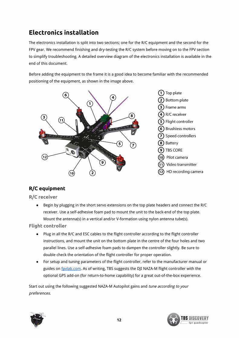
Before adding the equipment to the frame it is a good idea to become familiar with the recommended
positioning of the equipment, as shown in the image above.
R/C equipment
R/C receiver
● Begin by plugging in the short servo extensions on the top plate headers and connect the R/C
receiver. Use a self-adhesive foam pad to mount the unit to the back-end of the top plate.
Mount the antenna(s) in a vertical and/or V-formation using nylon antenna tube(s).
Flight controller
● Plug in all the R/C and ESC cables to the flight controller according to the flight controller
instructions, and mount the unit on the bottom plate in the centre of the four holes and two
parallel lines. Use a self-adhesive foam pads to dampen the controller slightly. Be sure to
double check the orientation of the flight controller for proper operation.
● For setup and tuning parameters of the flight controller, refer to the manufacturer manual or
guides on fpvlab.com. As of writing, TBS suggests the DJI NAZA-M flight controller with the
optional GPS add-on (for return-to-home capability) for a great out-of-the-box experience.
Start out using the following suggested NAZA-M Autopilot gains and tune according to your
preferences.
12

Setup Gain Pitch Roll Yaw Vertical
TBS 750KV 10x5 4S3300mAh 30A Basic/manual 134% 109% 93% 198%
Attitude 183% 143%
TBS 900KV 9x5 4S3300mAh 30A Basic/manual 166% 135% 131% 179%
Attitude 188% 176%
Other drivetrain setups (generally) Basic/manual 150% 140% 120% 110%
Attitude 140% 140%
Note: The pitch axis gain will in most cases be greater than the roll axis gain because of the inherentasymmetric design and weight distribution on the frame.
Motors
● Mount the brushless motors to the frame arms using standard M3x8mm hex screws supplied
with most brushless motors. Apply a small drop of medium threadlock to a secure the motors.
Feed the motor wires through the frame arm comb-pattern to minimize clutter.
● Plug in the bullet-connectors to the speed controllers. Swap any two wires to change the
direction of rotation. See the image below for the most commonly used setup (e.g. NAZA-M,
OpenPilot controllers are vertically mirrored).
Speed controllers
● With the frame arms mounted, use the zip ties to mount the speed controllers to the underside
of the arms. Avoid putting tension or stress on the motor- or speed controller-cables. Use a
self-adhesive pad to mount any BEC or control unit to the underside of the back-left speed
controller (e.g. NAZA VU-unit.)
13

● Calibrate the throttle range for each ESC individually (except for DJI and TBS BULLETPROOF
ESCs) by connecting the ESC directly to the throttle channel on the receiver and setting the
throttle stick high on power-on and then low until a confirmation beep is heard (motors
attached). The ESC has to be connected directly to the R/C receiver for this procedure to work.
TBS is offering a handy calibration cable for this purpose. The TBS BULLETPROOF ESCs come
pre-calibrated and do not need to be re-configured.
● One important note for ESCs that do not carry the “OPTO” label or are not TBS BULLETPROOF
designs, is that only one of the four ESCs should provide BEC 5V power to the flight controller.
The middle red wire on the end connector should be disconnected on three of the ESCs. If the
flight controller is providing power (e.g. NAZA-M VU-unit), all ESC BECs should be disconnected.
The reason for this is to avoid voltage oscillations caused by erroneous voltage-regulator
feedback.
Propellers
● Before adding the propellers it is a good idea to be sure they are balanced, as mentioned later
on. To avert any chance of injury, leave the propellers off until the flight controller configuration
has been completed.
● The only recommended propeller installation method is to use a precisely manufacturer prop
adaptors (never prop-saver with o-ring). The layering should be as follows; prop adaptor,
propeller, washer and (lock) nut. You can skip any bell screw as it may add unnecessary
vibrations.
● The TBS 750kV and 900kV motors have a 5mm prop shaft. This is compatible with Graupner
9x5-inch propellers. For Graupner 10x5-inch propellers you will need aluminium 8mm-to-5mm
reduction spacers available separately.
● Try to match the motor and propeller to suit your particular need. For extended flight time try to
achieve optimal efficiency. For a agile-flight get a responsive combination. Our general
recommendations are listed in the table below.
Motor type Propeller Flight characteristic
TBS 750kV brushless motor 9x5-inch Graupner type locked in
10x5-inch Graupner type long flight time
TBS 900kV brushless motor 9x5-inch Graupner type super responsive, locked in
10x5-inch Graupner type long flight time
DJI 920kV brushless motor 10x5-inch Graupner type long flight time
14

FPV gear
The FPV gear is designed to be installed on the front section of the frame to achieve as much separation
between the R/C- and FPV-radio environment as possible. Keep in mind that the former is listening
while the latter is broadcasting. The quieter the receiving conditions are, the better range and reliability
will be.
At the heart of this system sits the (optional) TBS CORE which provides a rudimentary OSD and clean
power distribution to the camera and video transmitter, regardless of input voltage. The frame already
includes a current sensor (50A) that works together with the TBS CORE to show current consumption
during flight.
Power supply
● To eliminate noise from causing problems on the FPV-side of the system, use a properly filtered
power supply. Any type will work but the TBS CORE is made to provide selectable 5V and/or 12V
to the video transmitter and camera regardless of input voltage (2S to 10S). It can supply video
transmitters with up to 1W (with minor airflow at 1W) of emitted power (EIRP) and a standard
FPV camera.
● If you are planning to fly with UHF, we highly recommend the Tin Shield to isolate the CORE
nicely from the rest of the electronics on board.
● Configure the CORE according to the required voltage for the FPV gear; pads marked VTX and
CAM can be configured to either 12V (0.65A max.) or 5V (2A max.). Solder a bridge between the
middle pad to either side for 12V or 5V. Do not solder all three pads.
Pilot camera
● Use the supplied camera plate to mount the pilot camera. The mounting pattern is designed to
be compatible with most standard 32x32 mm board cameras. You might need to break-away
excessive board support. Either use two zip ties or four M2x15mm screws and nuts to mount
the camera (use threadlock). Plug in the cable connector for the camera and insert the tabs on
the top and bottom of the camera frame in the corresponding routed gaps on the frame.
Changing the camera in the field is easy; just unclip the top tab.
● Next, decide whether you can use the supplied wires and connector socket on the bottom
plate, or connect the camera and video transmitter via the solder pads. The supplied picoblade
molex wires are designed to work with the TBS GREENHORN, TBS ROOKIE, Lawmate
transmitters, and TBS59/TBS69/TBS CHIPCHIP cameras. You can of course modify and solder
the wires to suit your specific need.
15

Video transmitter
● Put the video transmitter close to the front on the top plate. Use zip ties and/or self-adhesive
foam pads to fit the transmitter. TBS offers a custom made mounting bracket for easy vertical
install over the front-right frame arm.
● To avoid possible video interference, be sure to use a foam or gel pad between the frame and
VTx to reduce vibrations from propagating to the unit.
OSD (On Screen Display)
● You can use an optional, but recommended, OSD add-on to get live readout on screen about
the battery voltage, current consumption, receiver signal strength, flight time, position and
home location, to name a few. For a basic feature set we recommend the TBS CORE which
provide all but the latter two data points. A full feature set will require an OSD with a GPS
module (e.g. TBS EzOSD).
● The bottom plate has a RSSI trace for TBS CORE. The RSSI input header is located on the
middle-left side, right beneath the pin header for easy connection directly from a supported
R/C receiver. All major FPV R/C system vendors support either analog or digital (PWM) RSSI
output. Please read the TBS CORE documentation to find out how to configure the OSD. The
image below outlines the header point and trace.
● The next feature is a market first and it is a on-board current sensor on the back-right side, next
to the battery connection. Coupling this with the RSSI input makes a clutter-free and clean
build.
● To take advantage of the current sensor you only need to have a TBS CORE installed at the
designated area. The TBS CORE has to be configured to 100A for v1.1 frames and 50A for v1.2
and later frames. The current sensor output is compatible with similar OSD systems.
Instructions on how to install the TBS EzOSD can be found here: bit.ly/13oXPbj.
16

● Lastly, when all the R/C and FPV gear is installed, connect any the remaining R/C or RSSI cables
to the top plate and close the frame. Use the remaining spacer and frame arm screws to secure
the frame.
Caution: When testing for shorts on the TBS CORE, you may notice that VIN2 pins are shorted. This iscompletely normal and per design. Other neighboring pins should not be shorted!
17

Mounting HD camera
GoPro HD Hero
● The GoPro HD Hero cameras is the most commonly used HD recording camera, as of writing,
and was the camera of choice during the design process of the TBS DISCOVERY.
● A little background how modern HD video cameras function; the GoPro uses a method called
rolling shutter to capture video frames, as the name suggests, it is scanning across the image
sensor horizontally to record a single image (opposite to a single snapshot of a point in time of
the entire image sensor). This can cause issues when coupled with high frequency vibrations
produced by the drivetrain on a multirotor. If the frequency is close or matches the scanning
frequency, the image sensor will capture the minute movement (resonate with the vibrations).
This will cause the video to have clearly visible wavy wobbly lines, or more commonly known as
“jello”-effect.
Vibration free footage
● To get rid of most of the “jello”-effect, it is (always) good practice to begin with eliminating the
root cause of the vibrations rather than trying to applying various dampening methods.
● The primary culprit is unbalanced propellers, followed closely by unbalanced motors.
Fortunately, balancing them is a relatively easy task. TBS is offering a Prop Balancer for this
purpose. More details on how to perform the balancing, see our support forum at fpvlab.com.
● To reduce vibrations from propagating to the GoPro, use memory foam to add a separation
layer which absorbs the energy. Use the specially designed TBS Loveseat or cut two large pieces
which will cover the bottom and back of the GoPro. Secure the camera to the frame using two
thin rubber bands.
Consider using the GoPro settings in the tables below for “no-prop-in-view” and even less “jello”
footage.
GoPro HD Hero1:
Video format: NTSC to get 30fps
Video resolution: 1080p 30fps (medium angle) for 10x5-inch props
720p 30fps (wide angle) for 9x5-inch props
GoPro HD Hero2:
Video format: NTSC to get 30fps
Video resolution: 1080p 30fps high quality video
Video angle: Medium (127 degrees) for 10x5-inch props
Wide (170 degrees) for 9x5-inch props
18

GoPro HD Hero3:
Video format: NTSC to get 30/60fps
Video resolution: 1080p 60fps less chance of “jello”
Video angle: Medium (127 degrees) for 10x5-inch props
Wide (170 degrees, padding neededbehind camera)
for 9x5-inch props
19
Center of Gravity optimization
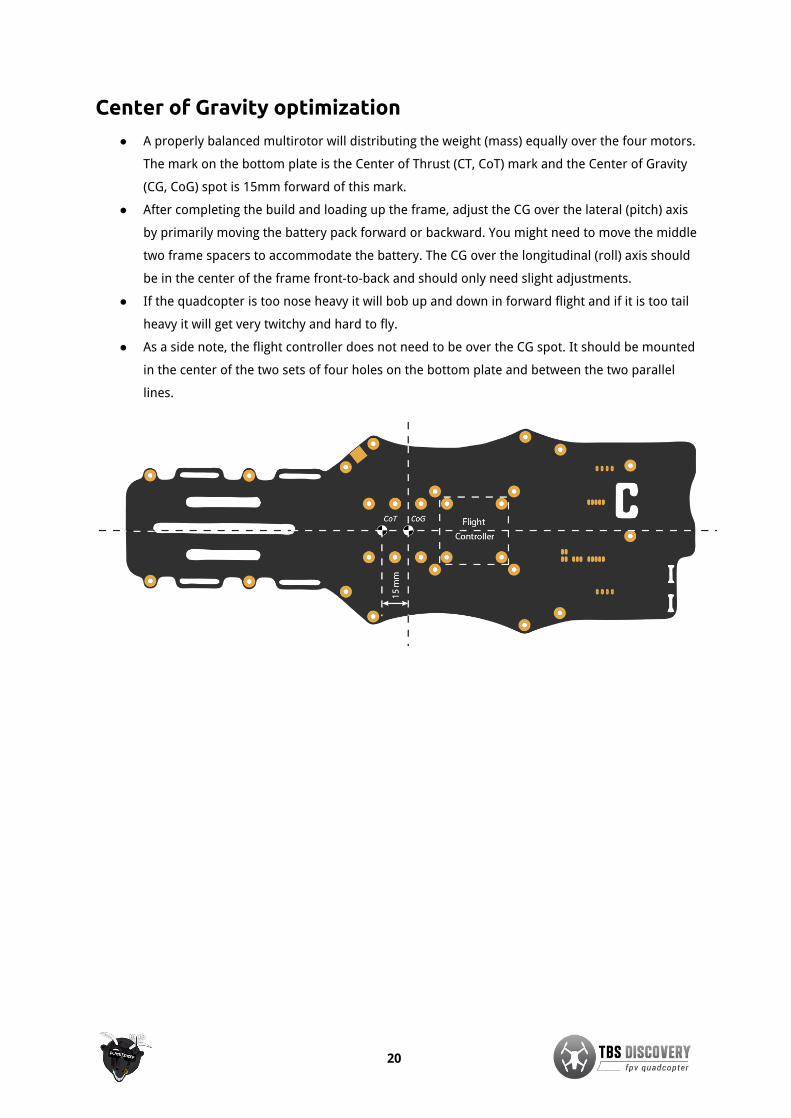
● A properly balanced multirotor will distributing the weight (mass) equally over the four motors.
The mark on the bottom plate is the Center of Thrust (CT, CoT) mark and the Center of Gravity
(CG, CoG) spot is 15mm forward of this mark.
● After completing the build and loading up the frame, adjust the CG over the lateral (pitch) axis
by primarily moving the battery pack forward or backward. You might need to move the middle
two frame spacers to accommodate the battery. The CG over the longitudinal (roll) axis should
be in the center of the frame front-to-back and should only need slight adjustments.
● If the quadcopter is too nose heavy it will bob up and down in forward flight and if it is too tail
heavy it will get very twitchy and hard to fly.
● As a side note, the flight controller does not need to be over the CG spot. It should be mounted
in the center of the two sets of four holes on the bottom plate and between the two parallel
lines.
20

Good practices
We have compiled a list of all of the things that have been tried and tested in countless environments
and situations by TBS crew and other experienced FPV pilots.
Follow these simple rules, even if rumors on the internet suggest otherwise, and you will have success
in FPV.
● Start with the bare essentials and add equipment one step at a time, after each new equipment
was added to proper range- and stress tests.
● Do not fly with a video system that is capable of outperforming your R/C system in terms of
range.
● Do not fly with a R/C frequency higher than the video frequency (e.g. 2.4GHz R/C, 900MHz
video).
● Monitor the vitals of your plane (R/C link and battery). Flying with a digital R/C link without RSSI
is dangerous.
● Do not use 2.4GHz R/C unless you fly well within its range limits, in noise-free environments and
always within LOS. Since this is most likely never the case, it is recommended to not use 2.4GHz
R/C systems for longer range FPV.
● Do not fly at the limits of video, if you see noise in your picture, turn around and buy a
higher-gain receiver antenna before going out further.
● Shielded wires or twisted cables only, anything else picks up RF noise and can cause problems.
● When using powerful R/C transmitters, make sure your ground station equipment is properly
shielded.
● Adding Return-To-Home (RTH) to an unreliable system does not increase the chances of getting
your plane back. Work on making your system reliable without RTH first, then add RTH as an
additional safety measure if you must.
● Avoid powering the VTx directly from battery, step-up or step-down the voltage and provide a
constant level of power to your VTx. Make sure your VTx runs until your battery dies.
● Do not power your camera directly unless it works along the complete voltage range of your
battery. Step-up or step-down the voltage and provide a constant level of power to your
camera. Make sure your camera runs until your battery dies.
● A single battery system is safer than using two dedicated batteries for R/C and FPV. Two
batteries in parallel even further mitigate sources of failure.
● For maximum video range and “law compatibility”, use 2.4GHz video with high-gain antennas.
● When flying with R/C buddies that fly on 2.4GHz, or when flying in cities, it is perfectly possible
to use 2.4GHz video provided you stick to the channels that do not lie in their band (CH5 to CH8
for Lawmate systems, available from TBS).
● Do not use diversity video receivers as a replacement for pointing your antennas, diversity
should be used to mitigate polarization issues.
21

● Improving the antenna gain on the receiver end is better than increasing the output power
(except in RF-noisy areas). More tx power causes more issues with RF on your plane. 500mW is
plenty of power!
● Try to achieve as much separation of the VTx and R/C receiver as possible to lower the RF noise
floor and EMI interference.
● Do not buy the cheapest equipment unless it is proven to work reliably (e.g. parts falling off,
multitudes of bug fix firmware updates, community hacks and mods are a good indicator of
poor quality and something you do NOT want to buy for a safe system). Do due diligence and
some research before sending your aircraft skyward.
22

Troubleshooting
● Issue: Horizontal lines in pilot video downlink
Solution: If there are lines in the video during flight that disappear as soon as you land, your
video transmitter is exposed to too much vibrations. Memory foam in conjunction with the
Flame Wheel VTx mount will take out the vibrations in an instant and give you crystal-clear
video.
● Issue: Motor(s) doesn’t start
Solution: It is probably a lazy start syndrome, some information on that is available here:
bit.ly/15wNLk4. You should calibrate your ESC throttle endpoints, details on how to perform
this: bit.ly/110deyX. We have a calibration cable available which speeds up the process. Please
remember to remove the props before doing that.
● Issue: Got a TBS CORE and no OSD or only voltage
Solution: The TBS CORE needs to be enabled. This is done by soldering a bridge on the
"ENABLE" pads at the face of the TBS CORE. If you only see voltage, you need to configure the
CORE for the right current sensor and for current consumption display. The manual tells you all
about that.
● Issue: Want to use backup battery for TBS CORE
Solution: A backup battery can be soldered to the two pads marked VIN2/GND but in reality it is
not really advisable; if the main battery is dead the quad will fall to the ground regardless (a
wing can glide to a safe landing). Additionally, since the VIN2 pads are shorted on the bottom
plate, you may not connect the pin headers for VIN2 and use a backup battery system.
23

Recommended parts
Below is a list of compatible R/C and FPV gear for the TBS Discovery quadrotor. This will hopefully make
it easier to pick up spare parts and upgrades.
Power sets
TBS 750kV Motor / ESC Combo
A very sweet Motor/ESC combination which
offers great value. This is the system that was
flown in most TBS DISCOVERY videos due to its
long flight times (10-12mins on 4S 3.3Ah).
● 4x TBS BULLETPROOF 30A ESC (flashedwith SimonK Firmware)
● 4x TBS 750kV Motor with M5 propmount hubs
TBS 900kV Motor / ESC Combo
For the more sophisticated, agile-flight loving
pilot or for those requiring
super-vibration-resistant and high quality
motors.
● 4x TBS BULLETPROOF 30A ESC (flashedwith SimonK Firmware)
● 4x TBS 900kV Motor with M5 propmount hubs
Individual parts
Motors
● TBS 900KV or Tiger Motors MT2216-10/11 900KV brushless motor (5mm shaft)
● TBS 750KV or RCTimer A2830-14 750KV brushless motor
● DJI 2212 920KV brushless motor (8mm shaft)
● Sunnysky 2216-12 800KV brushless motor
Speed controllers
● TBS 30A Multicopter SimonK firmware speed controller
● DJI OPTO 30A no-BEC speed controller
● Tiger Motors 18A BEC speed controller
● HobbyKing F-20A or F-30A BEC programmable ESC with SimonK firmware
24

Flight controller
● DJI NAZA-M with optional GPS
● OpenPilot CopterControl 3D
R/C Transmitter/Receiver
● Futaba 8FG / 7C with included receiver R6208SB / R617FS
● Graupner MX-12 radio with included GR-6 receiver
● ImmersionRC EzUHF 8ch Diversity receiver
● ImmersionRC EzUHF 8ch Lite receiver
Propellers
● Graupner E-Prop 9x5-inch propellers
● Graupner E-Prop 10x5-inch propellers
● GemFan E-Propeller 10x5 Carbon Fiber propellers
● RCTimer Carbon Fiber 9x5-inch propellers
● RCTimer Carbon Fiber 10x5-inch propellers
Battery
● TBS 4S 4500mAh 30C or KyPOM KT4500/35-4S Lipo pack
● TBS 4S 3300mAh 30C or KyPOM KT3300/35-4S Lipo pack
● Gens Ace 4S 3300mAh 25C Lipo pack
● Zippy Compact 4S 4000mAh 25C Lipo pack
● Turnigy nano-tech 4S 3300mAh 35C Lipo pack
FPV transmitter
● Lawmate TM-240500-LM 2.4GHz 500mW transmitter
● TBS ROOKIE 5.8GHz 200mW transmitter
● TBS GREENHORN 5.8GHz 25mW transmitter
● BosCam TS-353 5.8GHz 400mW transmitter
● ImmersionRC 5.8ghz 600mW A/V transmitter
FPV camera
● TBS69 or TBS59 FPV camera
● Security Camera 2000 PZ0420 or CMQ1993X (IR blocked) 600TVL camera
25

Spare parts
You can either get spare parts directly from us (team-blacksheep.com) or from one of our distributors
and retailers near you.
Our ever-growing list of retailers is published on the left at team-blacksheep.com/shop.
26

Appendix
● Frame assembly diagram
● Electronics installation diagram
● Center of Gravity diagram
Special thanks to DJI Innovations for making this quadrotor possible.
Manual written and designed by ivc.no in cooperation with TBS.
27

1
1
2
2
3
3
4
4
5
5
6
6
7
7
8
8
A A
B B
C C
D D
E E
F F
SHEET 1 OF 1
DRAWN
CHECKED
QA
MFG
APPROVED
TBS Associates Inc 31.07.2013
DWG NO
tbs_discovery_pro_frame
TITLE
SIZE
A2SCALE
REV

Battery
Video transmitter
FPV camera
CH1CH2CH3CH4CH5CH6CH7CH8
RC receiver
Speed controller
Speed controller
GoPro camera
Motor - CW
Motor - CCWMotor - CW Speed controller
Motor - CCW Speed controllerFlight controller
(Optional)
GPS
1 2
3 4
5 6
7 8
8 7 6 5 4 3 2 1
VTX
_PW
RV
TX_G
ND
VTX
_VID
VTX
_AU
D
CA
M_P
WR
CA
M_G
ND
CA
M_V
IDA
UD
_IN
+
-- + --
+
--
+
--
Top frame
Bottom frame
TBS DISCOVERYS + -
S +
-
Battery
+
BEC regulator
DJI
RSSIG
ND
by ivc.no/tbsdiscovery - 08.2013
Curr. sensor
+ --
+ --
+--
+--
VTX
TBS
CORE
CA
M
VIN
2
RSSI
Enab
le
OSD
12V
5V
CAM
V+ GN
DVi
deo
AudL
AudR
GN
DVi
nCu
rr. s
ens
V+G
ND
Vide
oAu
dLAu
dR
12V
5V
ESCs with 5V BEC, disconnect RED wireESCs without 5V BEC, leave RED wire
CoT CoG
Electronics installation
(For channel setup, refer to the manufacurer’s manual)
(For flight controller setup, refer to the manufacurer’s manual)
RSSI signal
NAZA

Median
Median
Cent
er o
f Gra
vity
Cente
r of T
hrust
by ivc.no/tbsdiscovery - 02. 2013
Center of Gravity diagram