Tau to Rhapsody Diagrams Mapping - IBM · 4.5. Composite Structure diagrams Tau Rhapsody Comment /...
25
1 Tau to Rhapsody Diagrams Mapping 1. Overview .......................................................................................................................................................................................................................................................... 2 2. Some general limitations .................................................................................................................................................................................................................................. 2 3. All diagrams ..................................................................................................................................................................................................................................................... 2 4. Static diagrams ................................................................................................................................................................................................................................................. 3 4.1. Class diagram .......................................................................................................................................................................................................................................... 3 4.2. Component diagram ................................................................................................................................................................................................................................ 8 4.3. Deployment Diagram .............................................................................................................................................................................................................................. 9 4.4. Package diagram .................................................................................................................................................................................................................................... 10 4.5. Composite Structure diagrams ............................................................................................................................................................................................................... 11 4.6. Object Diagram ..................................................................................................................................................................................................................................... 12 5. Dynamic diagrams.......................................................................................................................................................................................................................................... 13 5.1. Use Case diagram .................................................................................................................................................................................................................................. 13 5.2. Sequence diagram .................................................................................................................................................................................................................................. 15 5.3. Activity diagram .................................................................................................................................................................................................................................... 18 5.4. Interaction Overview ............................................................................................................................................................................................................................. 21 5.5. State Machine diagram .......................................................................................................................................................................................................................... 22
-
Upload
vuongkhuong -
Category
Documents
-
view
223 -
download
0
Transcript of Tau to Rhapsody Diagrams Mapping - IBM · 4.5. Composite Structure diagrams Tau Rhapsody Comment /...
1
Tau to Rhapsody Diagrams Mapping
1. Overview .......................................................................................................................................................................................................................................................... 2
2. Some general limitations .................................................................................................................................................................................................................................. 2
3. All diagrams ..................................................................................................................................................................................................................................................... 2
4. Static diagrams ................................................................................................................................................................................................................................................. 3
4.1. Class diagram .......................................................................................................................................................................................................................................... 3 4.2. Component diagram ................................................................................................................................................................................................................................ 8 4.3. Deployment Diagram .............................................................................................................................................................................................................................. 9 4.4. Package diagram .................................................................................................................................................................................................................................... 10 4.5. Composite Structure diagrams ............................................................................................................................................................................................................... 11 4.6. Object Diagram ..................................................................................................................................................................................................................................... 12
5. Dynamic diagrams .......................................................................................................................................................................................................................................... 13
5.1. Use Case diagram .................................................................................................................................................................................................................................. 13 5.2. Sequence diagram .................................................................................................................................................................................................................................. 15 5.3. Activity diagram .................................................................................................................................................................................................................................... 18 5.4. Interaction Overview ............................................................................................................................................................................................................................. 21 5.5. State Machine diagram .......................................................................................................................................................................................................................... 22
2
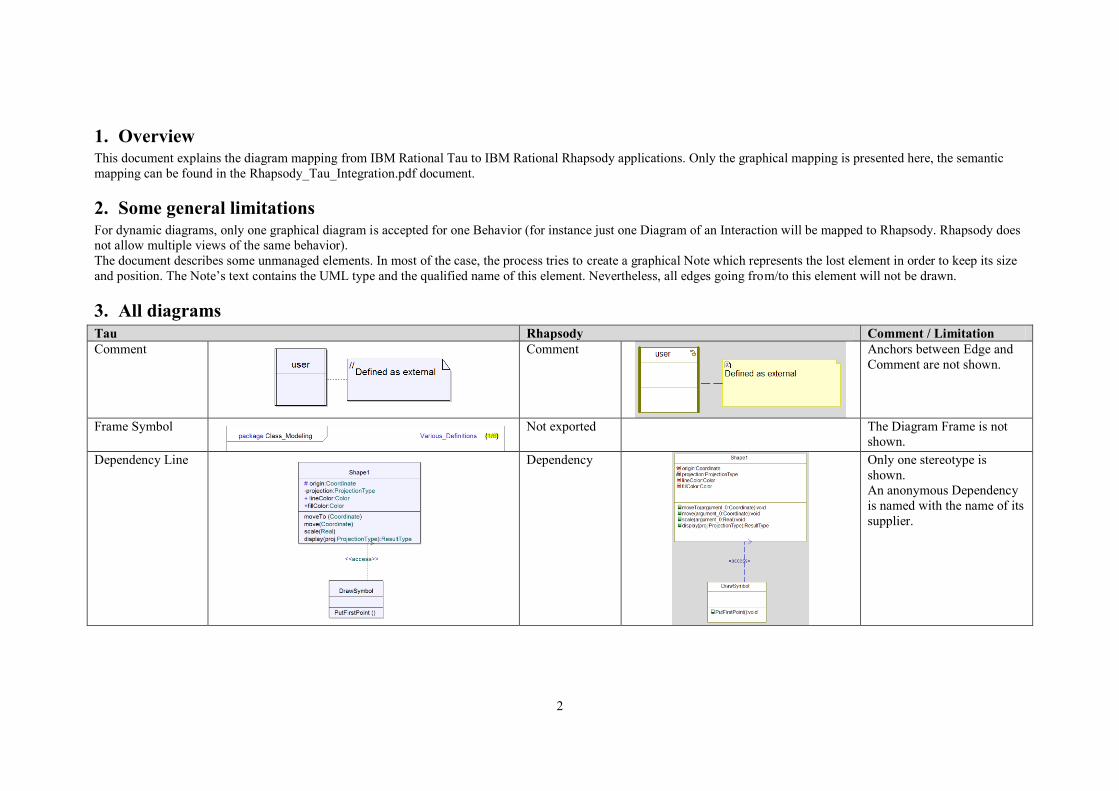
1. Overview This document explains the diagram mapping from IBM Rational Tau to IBM Rational Rhapsody applications. Only the graphical mapping is presented here, the semantic
mapping can be found in the Rhapsody_Tau_Integration.pdf document.
2. Some general limitations For dynamic diagrams, only one graphical diagram is accepted for one Behavior (for instance just one Diagram of an Interaction will be mapped to Rhapsody. Rhapsody does
not allow multiple views of the same behavior).
The document describes some unmanaged elements. In most of the case, the process tries to create a graphical Note which represents the lost element in order to keep its size
and position. The Note’s text contains the UML type and the qualified name of this element. Nevertheless, all edges going from/to this element will not be drawn.
3. All diagrams
Tau Rhapsody Comment / Limitation
Comment
Comment
Anchors between Edge and
Comment are not shown.
Frame Symbol
Not exported
The Diagram Frame is not
shown.
Dependency Line
Dependency
Only one stereotype is
shown.
An anonymous Dependency
is named with the name of its
supplier.

3
4. Static diagrams
4.1. Class diagram
Tau Rhapsody Comment / Limitation
Class Diagram (in
Package)
Object Model
Diagram
Class Diagram
(not in Package)
Structure Diagram
Class Symbol
Class
Abstract feature (italic name)
is not shown.
Interface Symbol
Interface
See Class Symbol in Class
diagram.
4
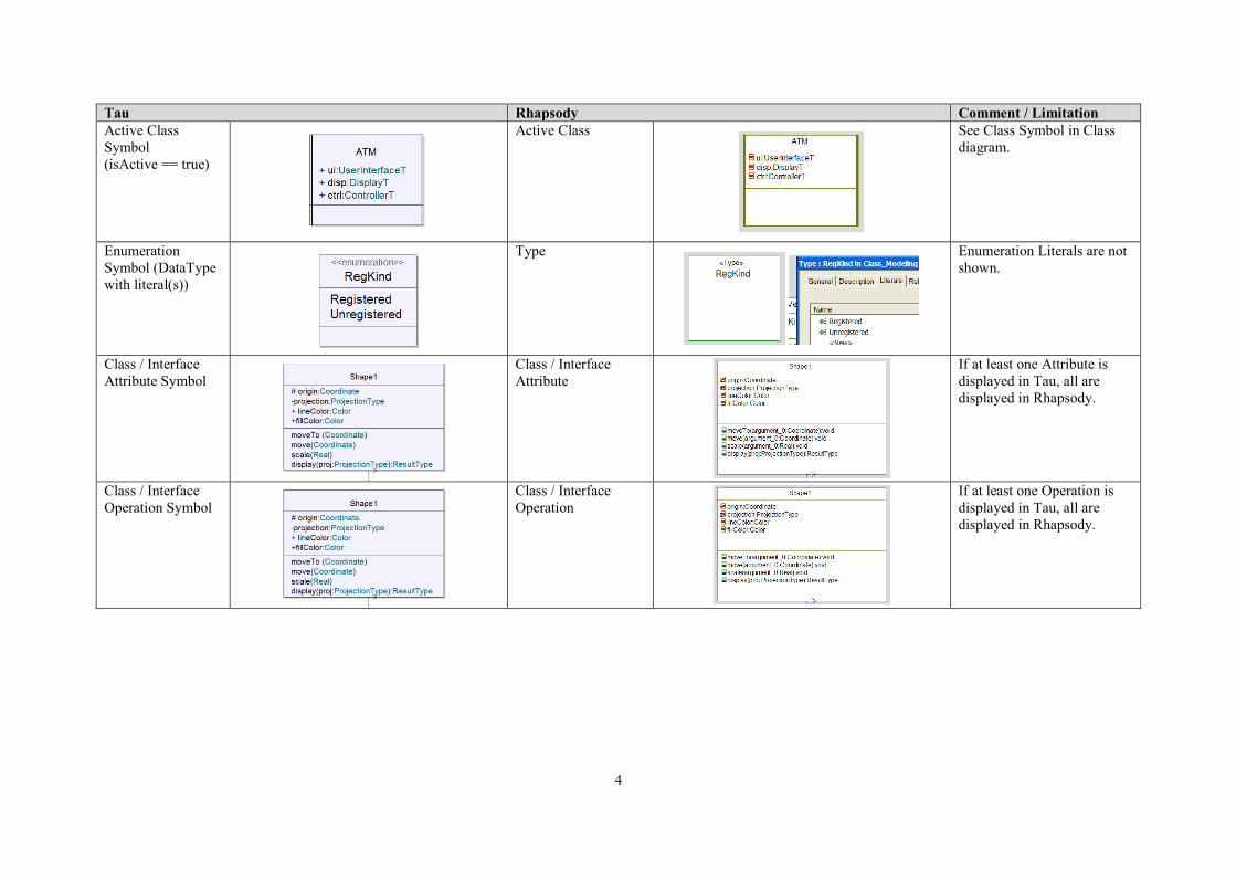
Tau Rhapsody Comment / Limitation
Active Class
Symbol
(isActive == true)
Active Class
See Class Symbol in Class
diagram.
Enumeration
Symbol (DataType
with literal(s))
Type
Enumeration Literals are not
shown.
Class / Interface
Attribute Symbol
Class / Interface
Attribute
If at least one Attribute is
displayed in Tau, all are
displayed in Rhapsody.
Class / Interface
Operation Symbol
Class / Interface
Operation
If at least one Operation is
displayed in Tau, all are
displayed in Rhapsody.
5
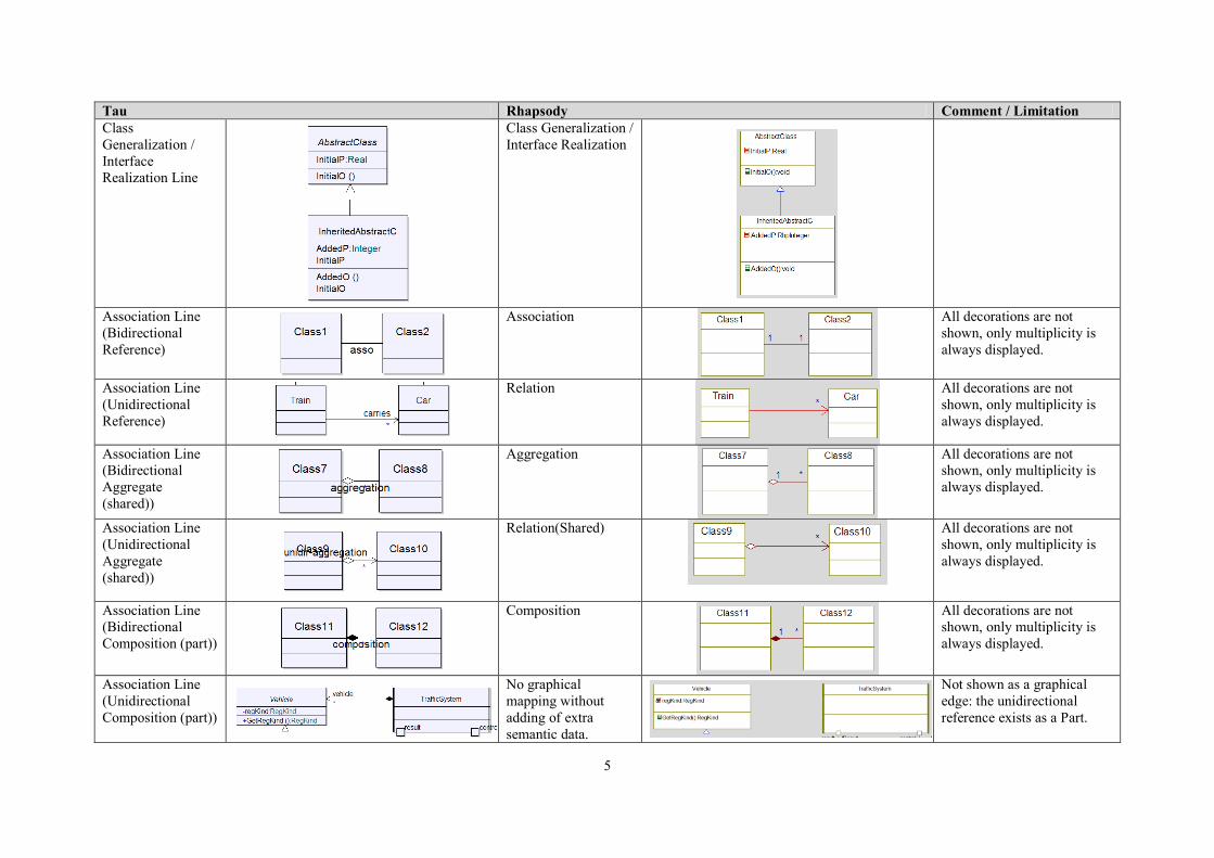
Tau Rhapsody Comment / Limitation
Class
Generalization /
Interface
Realization Line
Class Generalization /
Interface Realization
Association Line
(Bidirectional
Reference)
Association
All decorations are not
shown, only multiplicity is
always displayed.
Association Line
(Unidirectional
Reference)
Relation
All decorations are not
shown, only multiplicity is
always displayed.
Association Line
(Bidirectional
Aggregate
(shared))
Aggregation
All decorations are not
shown, only multiplicity is
always displayed.
Association Line
(Unidirectional
Aggregate
(shared))
Relation(Shared)
All decorations are not
shown, only multiplicity is
always displayed.
Association Line
(Bidirectional
Composition (part))
Composition
All decorations are not
shown, only multiplicity is
always displayed.
Association Line
(Unidirectional
Composition (part))
No graphical
mapping without
adding of extra
semantic data.
Not shown as a graphical
edge: the unidirectional
reference exists as a Part.
6
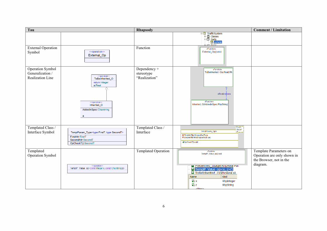
Tau Rhapsody Comment / Limitation
External Operation
Symbol
Function
Operation Symbol
Generalization /
Realization Line
Dependency +
stereotype
“Realization”
Templated Class /
Interface Symbol
Templated Class /
Interface
Templated
Operation Symbol
Templated Operation
Template Parameters on
Operation are only shown in
the Browser, not in the
diagram.
7
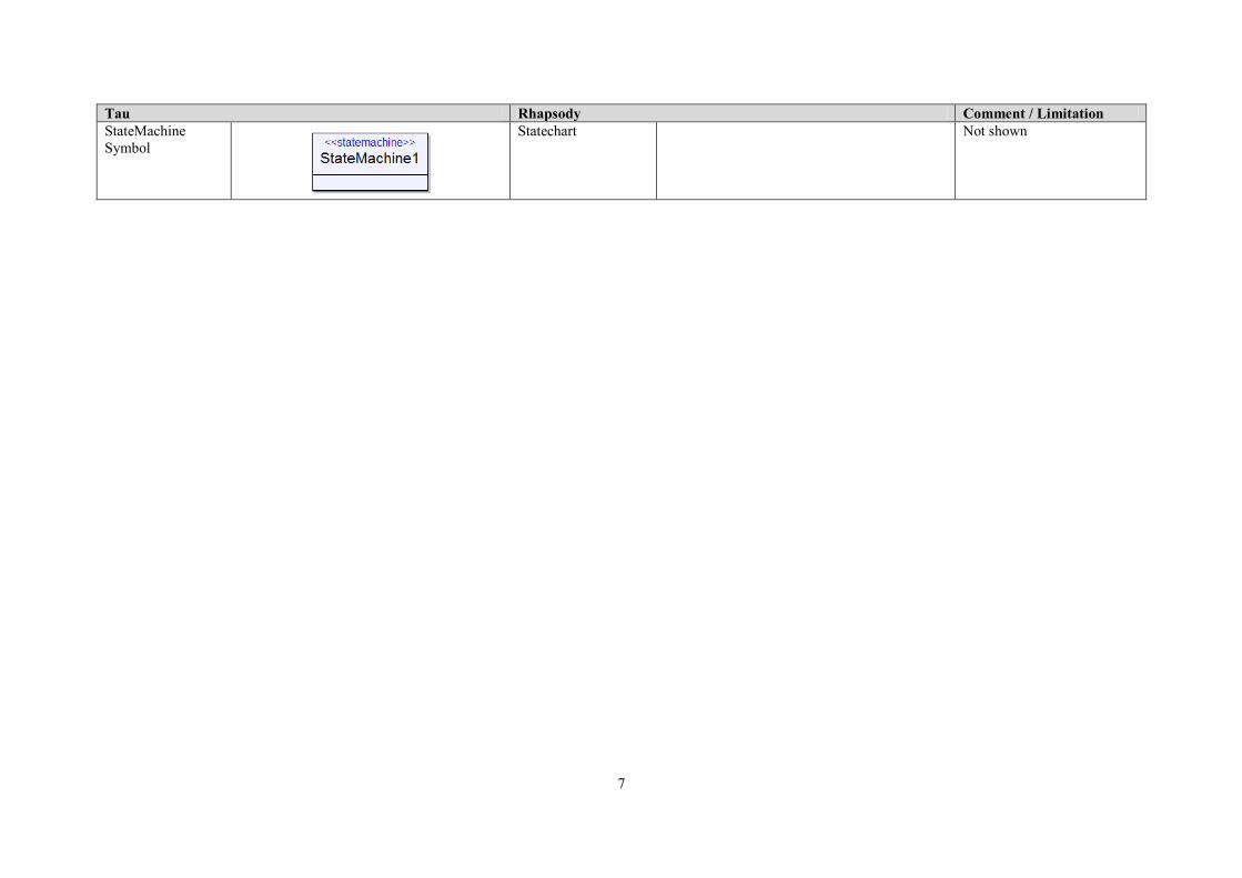
Tau Rhapsody Comment / Limitation
StateMachine
Symbol
Statechart
Not shown

8
4.2. Component diagram
Tau Rhapsody Comment / Limitation
Component Diagram
Component
Diagram
Component Symbol
Component
(Class with Port(s))
Port Symbol
Port
Required / Realized
Interface Symbol
Required / Provided
Interface
In Rhapsody, Required /
Provided Interface Symbols
are not shown in Component
diagram.

9
4.3. Deployment Diagram
Tau Rhapsody Comment / Limitation
Deployment Diagram
Object Model
Diagram
Artifact Symbol
File
Node Symbol
Class + “Node”
Stereotype
Deployment Specification
Symbol
Class
Execution Environment
Symbol
Class +
“ExecutionEnviron
ment” Stereotype
10
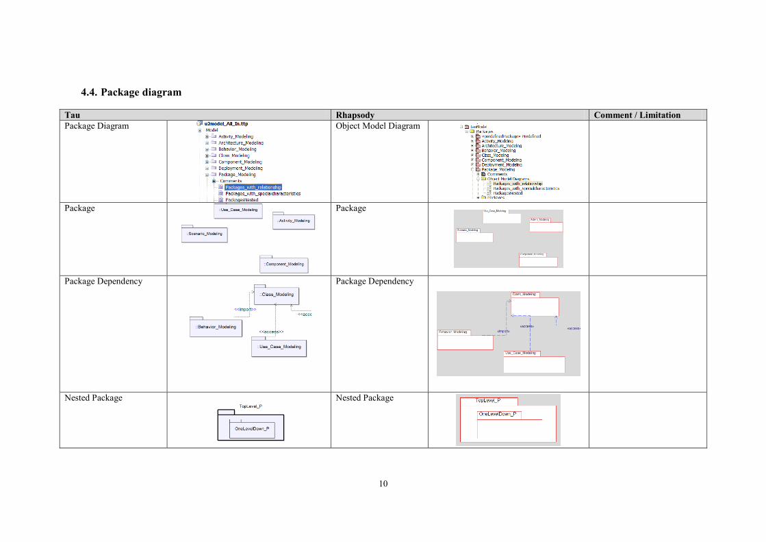
4.4. Package diagram
Tau Rhapsody Comment / Limitation
Package Diagram
Object Model Diagram
Package
Package
Package Dependency
Package Dependency
Nested Package
Nested Package
11
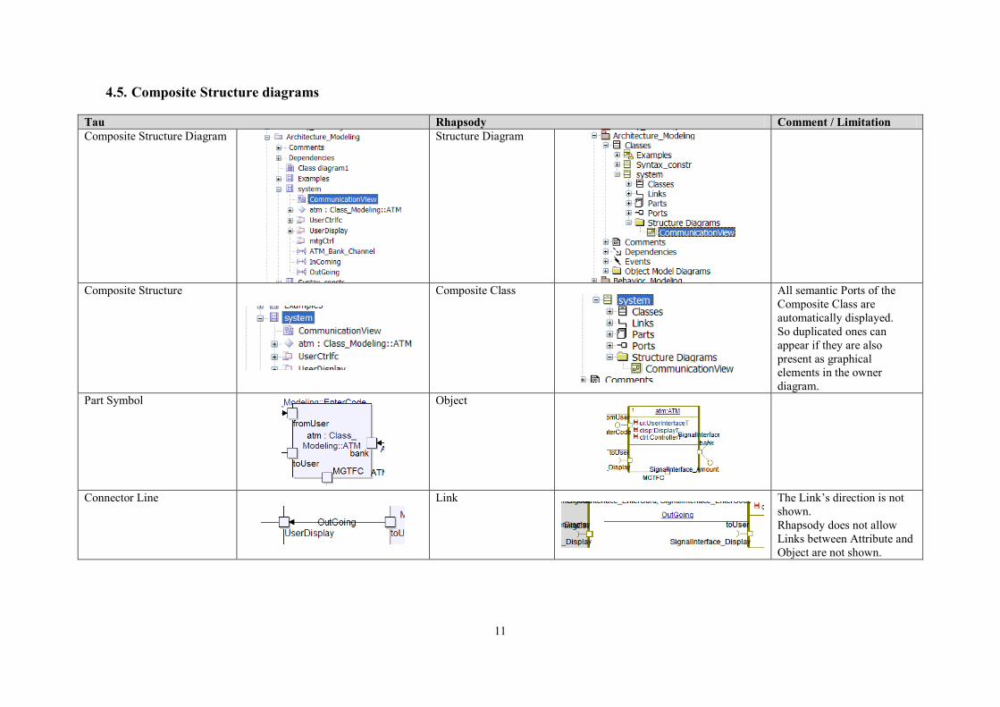
4.5. Composite Structure diagrams
Tau Rhapsody Comment / Limitation
Composite Structure Diagram
Structure Diagram
Composite Structure
Composite Class
All semantic Ports of the
Composite Class are
automatically displayed.
So duplicated ones can
appear if they are also
present as graphical
elements in the owner
diagram.
Part Symbol
Object
Connector Line
Link
The Link’s direction is not
shown.
Rhapsody does not allow
Links between Attribute and
Object are not shown.
12
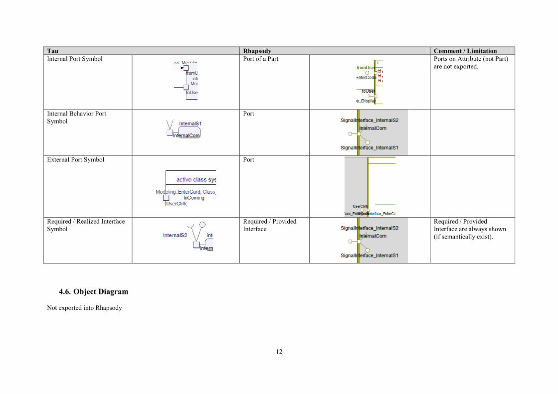
Tau Rhapsody Comment / Limitation
Internal Port Symbol
Port of a Part
Ports on Attribute (not Part)
are not exported.
Internal Behavior Port
Symbol
Port
External Port Symbol
Port
Required / Realized Interface
Symbol
Required / Provided
Interface
Required / Provided
Interface are always shown
(if semantically exist).
4.6. Object Diagram
Not exported into Rhapsody
13
5. Dynamic diagrams
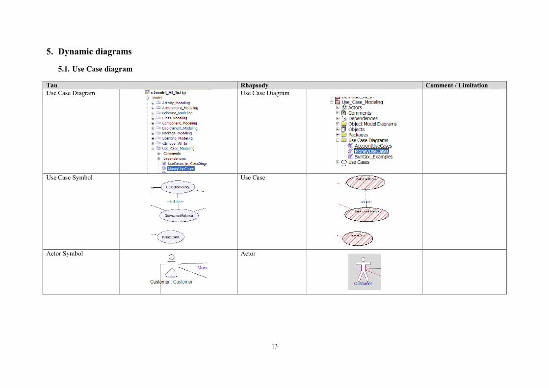
5.1. Use Case diagram
Tau Rhapsody Comment / Limitation
Use Case Diagram
Use Case Diagram
Use Case Symbol
Use Case
Actor Symbol
Actor
14
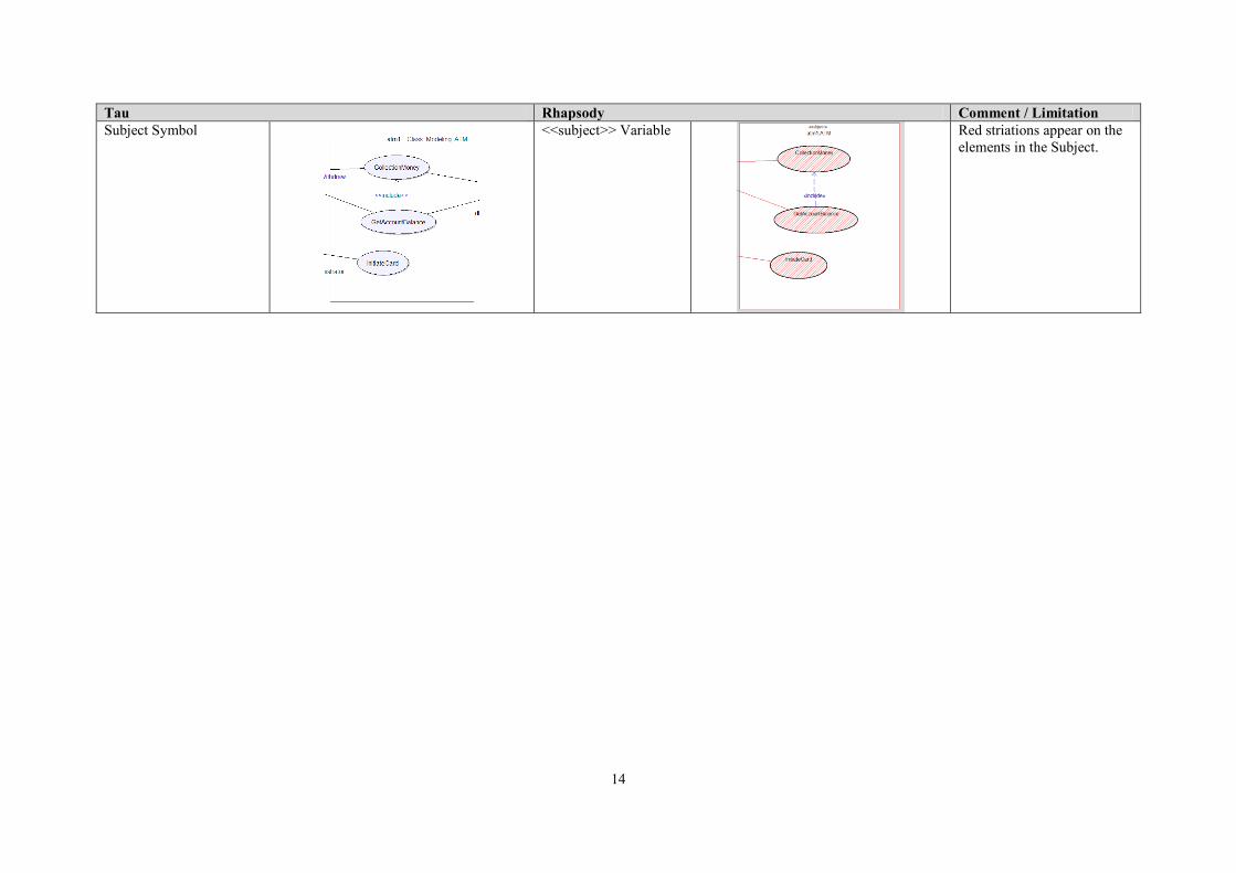
Tau Rhapsody Comment / Limitation
Subject Symbol
<<subject>> Variable
Red striations appear on the
elements in the Subject.
15
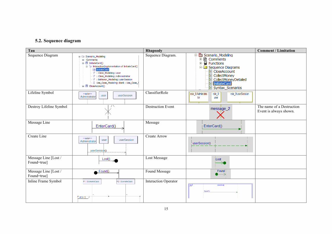
5.2. Sequence diagram
Tau Rhapsody Comment / Limitation
Sequence Diagram
Sequence Diagram.
Lifeline Symbol
ClassifierRole
Destroy Lifeline Symbol
Destruction Event
The name of a Destruction
Event is always shown.
Message Line
Message
Create Line
Create Arrow
Message Line [Lost /
Found=true]
Lost Message
Message Line [Lost /
Found=true]
Found Message
Inline Frame Symbol
Interaction Operator

16
Tau Rhapsody Comment / Limitation
Reference Symbol
InteractionOccurrence
Method Call Line
Message
Method Reply Line
Reply Message
Method Suspension
Symbol
Execution Occurrence
Method Activation
Symbol
Execution Occurrence
Action Symbol
ConditionMark
State Symbol
ConditionMark
Continuation Symbol
Not exported
Shown as an empty box.
17
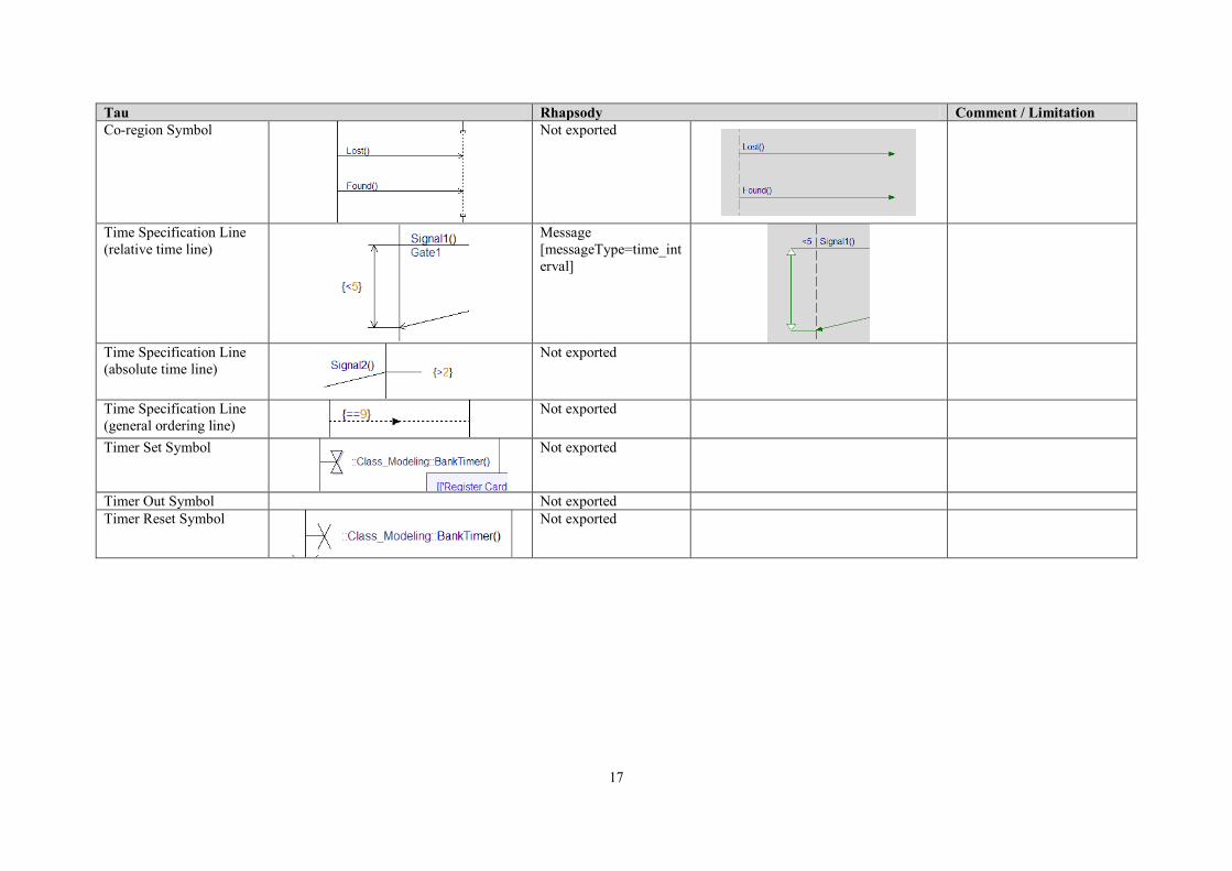
Tau Rhapsody Comment / Limitation
Co-region Symbol
Not exported
Time Specification Line
(relative time line)
Message
[messageType=time_int
erval]
Time Specification Line
(absolute time line)
Not exported
Time Specification Line
(general ordering line)
Not exported
Timer Set Symbol
Not exported
Timer Out Symbol Not exported
Timer Reset Symbol
Not exported
18
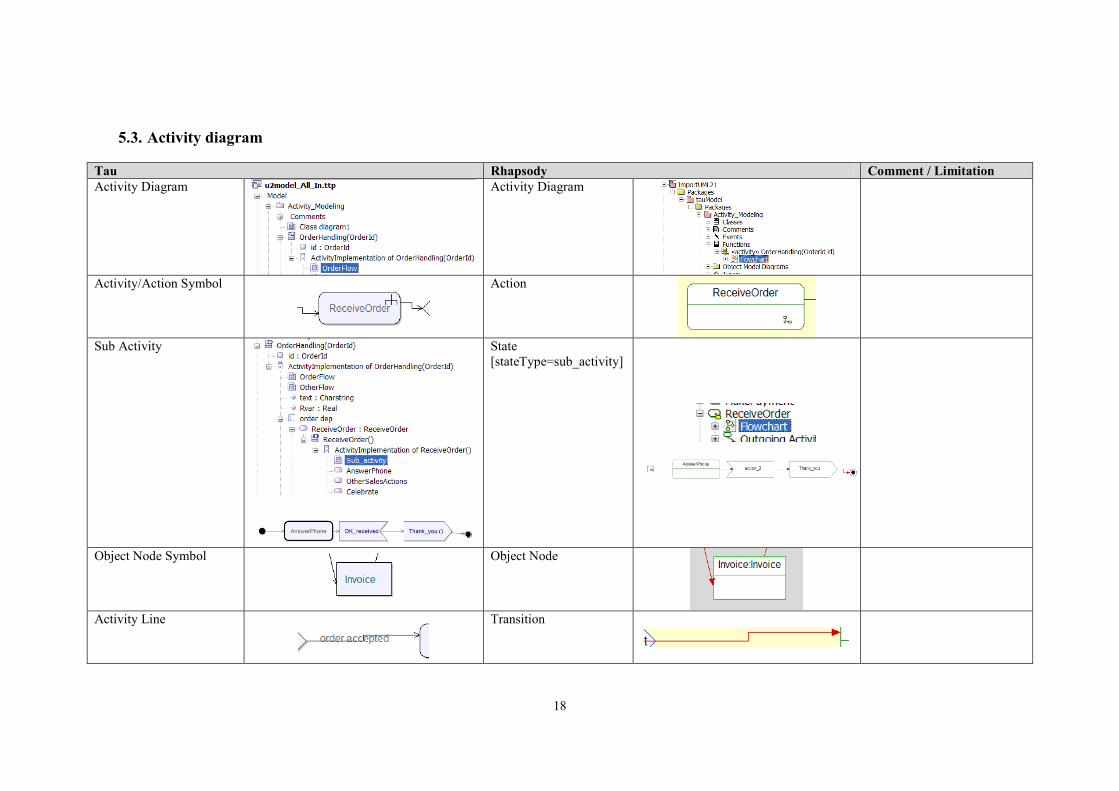
5.3. Activity diagram
Tau Rhapsody Comment / Limitation
Activity Diagram
Activity Diagram
Activity/Action Symbol
Action
Sub Activity
State
[stateType=sub_activity]
Object Node Symbol
Object Node
Activity Line
Transition

19
Tau Rhapsody Comment / Limitation
Initial Node Symbol
Default Transition
An InitialNode cannot be
drawn without its outgoing
transition.
Only one Default Transition
can be shown.
Default Transitions are not
shown into a SubActivity
Activity Final Symbol
Termination State
Flow Final Symbol
Termination State
Send Signal Symbol
Send Signal Action
Accept Event Symbol
Accept Event Action
Decision/Merge Symbol
Condition Connector
Transitions are shown in the
foreground of the condition.
Fork/Join Symbol
Fork/Join Sync Bar
A Fork/Join Sync Bar is
shown horizontally only.
Connector Symbol
Junction Connector
20
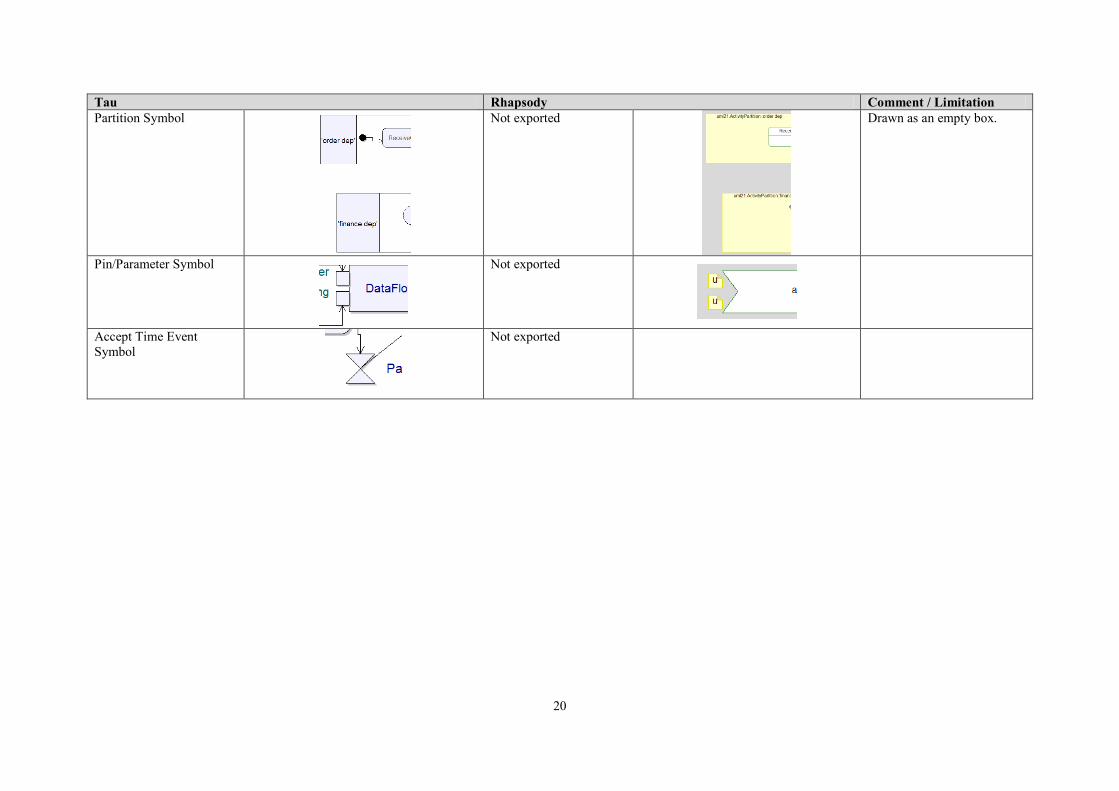
Tau Rhapsody Comment / Limitation
Partition Symbol
Not exported
Drawn as an empty box.
Pin/Parameter Symbol
Not exported
Accept Time Event
Symbol
Not exported

21
5.4. Interaction Overview
Tau Rhapsody Comment / Limitation
Interaction Overview
Activity Diagram
See ActivityDiagrams
ReferenceSymbol
CallOperation

22
5.5. State Machine diagram
Tau Rhapsody Comment / Limitation
StatechartDiagram
Statechart Diagram.
State Symbol
State
State with via clause
State with a Sub
Machine
Sub Machine
Sub Statechart
Default Transitions are not
shown into a Sub Statechart.
Simple Transition Symbol
Transition
Triggered Transition
Triggered Transition
Triggers are always shown.
23
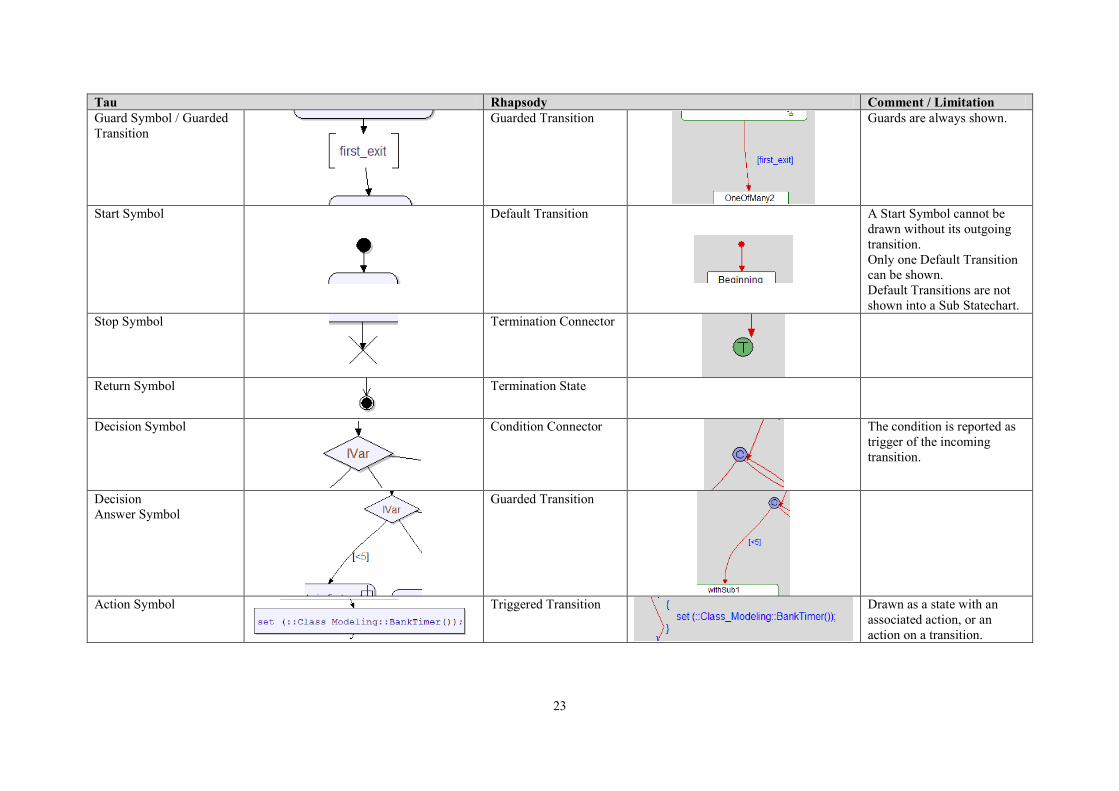
Tau Rhapsody Comment / Limitation
Guard Symbol / Guarded
Transition
Guarded Transition
Guards are always shown.
Start Symbol
Default Transition
A Start Symbol cannot be
drawn without its outgoing
transition.
Only one Default Transition
can be shown.
Default Transitions are not
shown into a Sub Statechart.
Stop Symbol
Termination Connector
Return Symbol
Termination State
Decision Symbol
Condition Connector
The condition is reported as
trigger of the incoming
transition.
Decision
Answer Symbol
Guarded Transition
Action Symbol
Triggered Transition
Drawn as a state with an
associated action, or an
action on a transition.

24
Tau Rhapsody Comment / Limitation
Multi State (State with
Asterisk State)
<<multiState>> State
The asterisk means all states
of the diagram.
Excluded Multi State
(State with Asterisk State,
including list of not
included States)
<<multiState>> State
The asterisk before
parenthesis means all states
of the diagram, excepting the
ones in the parenthesis.
Included Multi State
(State with State List)
<<multiState>> State
Signal Sending Symbol +
2 Flow Lines
Triggered Transition
Signal Receipt Symbol +
2 Flow Lines
Triggered Transition
History Symbol
History Connector
History State
History Connector
Junction Symbol
Not exported
25
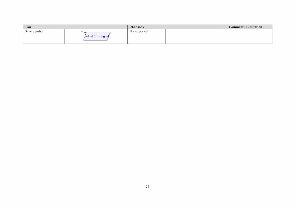
Tau Rhapsody Comment / Limitation
Save Symbol
Not exported