Task 4.3 - simulation lifecycle and data management · Simulation Lifecycle and Data Management...
28
RESEARCH REPORT VTT-R-03500-15 SIMPRO Simulation Lifecycle and Data Management (Case Studies) Authors: Romain Sibois, Timo Avikainen and Ali Muhammad Confidentiality: Public
Transcript of Task 4.3 - simulation lifecycle and data management · Simulation Lifecycle and Data Management...

RESEARCH REPORT VTT-R-03500-15
SIMPRO
Simulation Lifecycle and Data Management (Case Studies)
Authors: Romain Sibois, Timo Avikainen and Ali Muhammad
Confidentiality: Public


RESEARCH REPORT VTT-R-03500-15
3 (28)
Report’s title
Simulation Lifecycle and Data Management (Case Studies) Customer, contact person, address Order reference
Tekes/Matti Säynätjoki
Kyllikinportti 2, P.O. Box 69, FI-00101 Helsinki, FINLAND
Tekes: 40204/12
Project name Project number/Short name
Computational methods in mechanical engineering product
development
100553/SIMPRO
Author(s) Pages
Romain Sibois, Timo Avikainen and Ali Muhammad 28 Keywords Report identification code
modelling, simulation, data management, PLM, SLM VTT-R-03500-15 Summary
The activities in task 4.3 are the continuation of SIMPRO VTT subproject tasks 4.1 and 4.2. In task 4.1, the challenges regarding the use of simulation during product development were identified. The task 4.2 was dedicated to identify the potential solutions for the problems faced by the design engineers during the modelling and simulation phase of the product de-velopment and design process. The objectives of task 4.3 were to implement and test the identified Simulation Lifecycle Management (SLM) solutions for data exchange between simulation tools.
This report describes the research work carried out in task 4.3. During this task the accessi-bility and exchange of data among teams and between tools were studied by using the se-lected case studies. The case studies were defined together with the industrial partners of the SIMPRO project to ensure the industrial relevance of the results. The implementation of the case studies was done in ANSYS EKM (from ANSYS) and Simulia (from Dassault Systémes) which are commercially available SLM solutions. The research work shows that modern SLM tools can be used by industry to implement an improved product development and lifecycle data management process. However, such implementation is yet far from seamless. Integra-tion of proprietary design and simulation tools remains a major challenge and implementation of processes requires significant expertise. Additionally, the high price of the tools and con-tinuous dependence on the SLM tool vendors for the integration of new tools remains a bot-tleneck. These can be considered significant barriers for SMEs to employ SLM tools for im-proving their product development processes.
Confidentiality Public
Tampere 11.11.2015 Written by
Romain Sibois, Research Scientist
Reviewed by
Juha Kortelainen, Research Team Leader
Accepted by
Johannes Hyrynen, Technology Manager
VTT’s contact address
VTT Technical Research Centre of Finland, P.O. Box 1000, 02044, VTT, FINLAND
Distribution (customer and VTT)
Tekes/ Matti Säynätjoki, 1 original VTT/archive, 1 original
The use of the name of the VTT Technical Research Centre of Finland (VTT) in advertising or publication in part of
this report is only permissible with written authorisation from the VTT Technical Research Centre of Finland.

RESEARCH REPORT VTT-R-03500-15
4 (28)
Contents
Contents ................................................................................................................................. 4
Acronyms ............................................................................................................................... 5
1. Introduction ....................................................................................................................... 6
1.1 About the SIMPRO project ........................................................................................ 6
2. Objectives ......................................................................................................................... 7
3. Case study – Data exchange between simulations ........................................................... 8
3.1 Definition .................................................................................................................. 8 3.2 Case study implementation ....................................................................................... 9
4. Case study – Exchange of large data between locations ................................................ 15
4.1 Definition ................................................................................................................ 16 4.2 Case study implementation ..................................................................................... 17
5. Case study – Integration of Abaqus model to ANSYS EKM ............................................ 21
5.1 Abaqus test model .................................................................................................. 21 5.2 Case study implementation ..................................................................................... 21
6. Conclusions .................................................................................................................... 23
7. Bibliography .................................................................................................................... 24
Appendix A: Report generated by the Abaqus Report Generator ......................................... 25

RESEARCH REPORT VTT-R-03500-15
5 (28)
Acronyms
CAD Computer Aided Design
CAE Computer Aided Engineering
DMU Digital Mock-Up
FEA Finite Element Analysis
FEM Finite Element Method
JTA Joint Tolerance Analysis
MBS Multi-Body Simulation
PDM Product Data Management
PLM Product Lifecycle Management
SDM Simulation Data Management
SLM Simulation Lifecycle Management
SyS System Simulation

RESEARCH REPORT VTT-R-03500-15
6 (28)
1. Introduction
Today industries are required to provide new products with innovative and powerful features at accelerated pace. The integration of functionalities from various disciplines is a major source of innovation. Therefore products with multiple technologies need to be designed, verified and validated against multitude of requirements before being mass-produced and operated. This increased complexity of products is bringing new challenges during the devel-opment phase. The use of digital tools is considered to be an essential solution during the design process and it is increasingly becoming common. However, development of complex products with minimum or no physical prototypes requires ever increasing use of digital tools resulting in higher complexity of the design processes. It is particularly true within the mecha-tronic industry, where the current trend is going towards the simulation-based product devel-opment, where simulations become a central part of the design process.
However to realize the simulation-based product development process in practice, many technological challenges need to be overcome. The most obvious challenge is that the digital world is not the real world, and thus involves many uncertainties which have to be taken into account when designing and simulating the developed product. Additionally, increased com-plexity in product design exponentially increases the complexity of the design process and thus the demands on verification and validation [1]. New methods and new digital tools are constantly needed to be developed in order to deal with complex simulations and for evaluat-ing the simulation results.
Decision making process has become the crucial aspect of a product development and de-sign evolution. Relevant information including simulation results and uncertainties shall be available to make the right decision and to develop the system further. Therefore, flawless management of design and simulation data is essential when the requirements are validated in the digital world and it is currently a major research trend [2].
Simulation Lifecycle Management (SLM) tools allow the seamless combination of design and simulation tools within the same formalised process and thus reduce the risk of errors during the design process. SLM mainly focuses on the virtual world of the product lifecycle and manages simulations in a narrow collaboration with the Product Lifecycle Management (PLM) and integrates the capabilities of the simulation data management (SDM). SLM offers a clearer visibility for simulation data, and enables engineers and scientists to collaborate on a same simulation platform. SLM compliments SDM and PLM by associating behavioural simulation data and processes to the digital mock-ups. It is at the core of simulation-driven design where analyses become a fundamental part of product development. By managing the simulation process, SLM ensures: what will be done, when, by whom, and where results will be stored and archived. As a result SLM transforms simulation from a specialty operation to an enterprise product development process.
1.1 About the SIMPRO project
Computational methods in mechanical engineering product development – SIMPRO is a jointly funded Tekes (the Finnish Funding Agency for Technology and Innovation) research project that focuses on the application of computational methods in the product development of mechanical systems and products. The project has the following points of view to the top-ic: 1) high-performance computing in mechanical engineering, 2) optimisation, design studies and analyses, 3) requirement- and customer-based product development, and 4) modelling and results data management. The SIMPRO project is categorised by Tekes as public re-search networked with companies.

RESEARCH REPORT VTT-R-03500-15
7 (28)
2. Objectives
The background of this SIMPRO VTT subproject task 4.3 consists of the reports written un-der the task 4.1 [3] and task 4.2 [4]. The literature review in task 4.1 defined the current prac-tices in the industry and particular needs of the Finnish industry. The task 4.2 was aimed to identify the industrial needs and highlight potential solutions for modelling and simulation data management.
The research work in task 4.3 Utilisation of simulation over the product lifecycle was aimed to study commercial SLM solutions which can support the simulation based product develop-ment process. The tools were provided by the SIMPRO project partners for the evaluation during the project:
- Dassault Systèmes – Simulia
- ANSYS – ANSYS EKM (Engineering Knowledge Management)
The case studies were used for the evaluation of these SLM solutions. The case studies were defined together with the industrial partners of the SIMPRO project to ensure the indus-trial relevance of the results. The research work was aimed to answer some key questions for a better understanding of the major issues currently faced in the Finnish industry concern-ing simulation data management. To illustrate the research work, case studies were used to combine the multidisciplinary simulations along with the processes and simulation tools that are commercially available.
Following research objectives were selected on the basis of discussions with the SIMPRO industrial partners:
identify the industrially relevant case studies,
implement the case studies with commercially available tools,
study the accessibility and exchange of data among teams and between the selected tools and
identify the practical limitations faced by engineers while using the tools.

RESEARCH REPORT VTT-R-03500-15
8 (28)
3. Case study – Data exchange between simulations
Nowadays multi-disciplinary simulations are extensively used especially during the product design process. Combining for instance MBS with virtual reality is common in certain engi-neering domains. This leads to difficulties in transferring data between tools from different disciplines, due to the lack of standardisation of data formats. Compatibility between software applications is an important feature, from the common office tool to very specific simulation software applications. Usually the stakeholders are from different fields and a wide range of software applications is in use.
3.1 Definition
The aim of the case study was to automate a common simulation process (Figure 1) that involved various commonly used tools, from Computer Aided Design (CAD) software applica-tions to knowledge management. This process was implemented in the ANSYS Workbench and ANSYS EKM. The case study required the seamless data exchange between various modelling and simulation tools during the design process of a complex system. The process accounts for the reporting phase by assuring the continuity and the transfer of data through data and simulation management tools.
Figure 1. Roadmap of the suggested simulation process.
The simulation process starts by listing requirements of the case study. The requirements are used by the engineer to create the model using CAD software (in this case SolidWorks). The boundary conditions to carry out the Finite Element Analysis (FEA) are listed in an Excel file, which are directly used as an input for FEA tools (in this case ANSYS). The results are compiled in an automatically generated report in Microsoft Word.
During the implementation several other characteristics of the ANSYS EKM where highlight-ed. Such as compatibility of the SLM system with CAD software applications, integration of simulation software applications (Abaqus, ANSYS and Matlab), traceability of the simulation data during the design process and data exchange between ANSYS modules and external tools.
To conduct the case study a CAD model of pendulum shown in Figure 2 was used. The pen-dulum was designed with the SolidWorks CAD application. Connectors which form the data integration links between ANSYS EKM and the different simulation and reporting tools were developed and implemented in order to automate the simulation process.

RESEARCH REPORT VTT-R-03500-15
9 (28)
Figure 2. CAD model of the Pendulum.
3.2 Case study implementation
The case study was implemented into ANSYS EKM in collaboration with an EDRMedeso expert. The ANSYS Workbench was used as the graphical user interface while ANSYS EKM played the role of the data repository.
Figure 3 shows the global view of the implementation. The global environment consisted of three main working interfaces: the workbench project was built on the ANSYS Workbench, ANSYS EKM repository stored and linked the related files as well as the connectors to the external application. ANSYS EKM was also connected to external Product Data and Lifecy-cle management system where 3D CAD models were stored.
Figure 3. Implementation of the case study 1 in ANSYS EKM.
The simulation process was built under the Workbench project (Figure 4). The CAD model of Figure 2 in the case study consisted of a single assembly consisting of five parts. Each part had its own properties such as mass, dimensions, material and other data attributed to it. Boundary conditions and initial data were located in an Excel file under which parameters

RESEARCH REPORT VTT-R-03500-15
10 (28)
were listed and used as the input parameters in the ANSYS Workbench. The Excel add-in was originally included in the ANSYS Workbench so the integration was straightforward.
Figure 4. ANSYS Workbench user interface.
RESEARCH REPORT VTT-R-03500-15
11 (28)
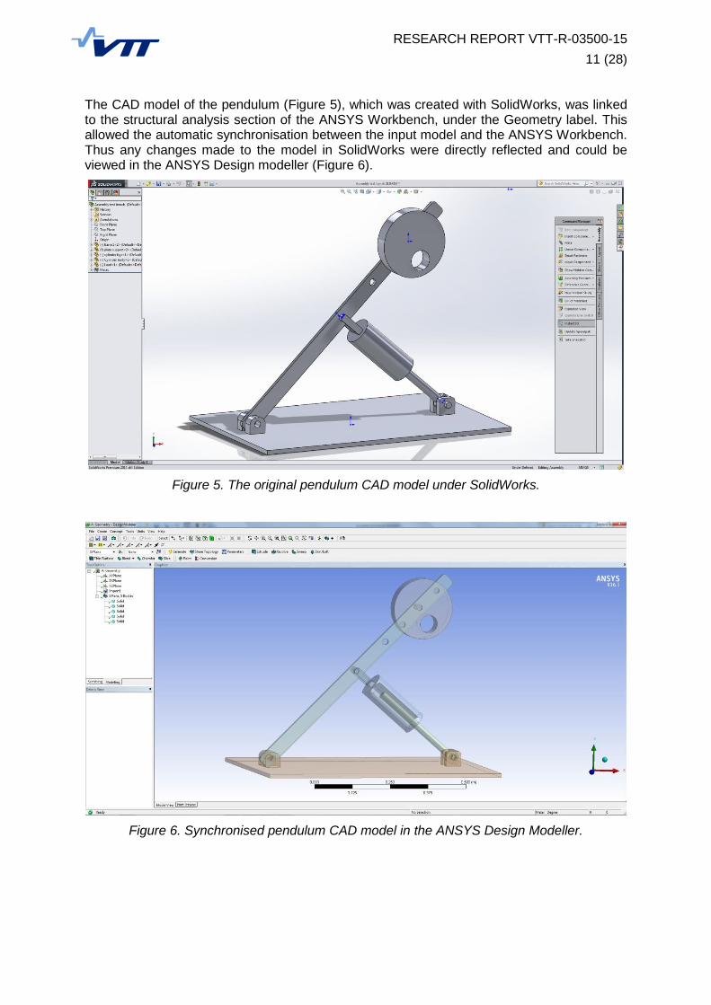
The CAD model of the pendulum (Figure 5), which was created with SolidWorks, was linked to the structural analysis section of the ANSYS Workbench, under the Geometry label. This allowed the automatic synchronisation between the input model and the ANSYS Workbench. Thus any changes made to the model in SolidWorks were directly reflected and could be viewed in the ANSYS Design modeller (Figure 6).
Figure 5. The original pendulum CAD model under SolidWorks.
Figure 6. Synchronised pendulum CAD model in the ANSYS Design Modeller.

RESEARCH REPORT VTT-R-03500-15
12 (28)
The ‘Setup’ label in the ANSYS Workbench corresponded to the ANSYS Mechanical module where static simulation can be applied to the model. A FEM mesh was assigned to the different components of the assembly, thus loads and contraints could be applied and finaly the simulation result could be computed (Figure 7).
Figure 7. Example of a static simulation.
The parameters of the simulations, such as forces, loads or material properties, were listed in an Excel file in order to be used as the inputs for the simulation. In the same way, simulation results could be used as the input for updating the Excel file data. The list of parameters (Figure 8), built in the ANSYS Workbench, was used as the inputs for the different simula-tions planned in the simulation process.
Figure 8. List of input and outputs parameters.
The parameter set was linked to the simulation connectors (Figure 9). Therefore, the results of one simulation could be used an input for the next simulation. The Excel file could be used as calculator, so new values can be computed to become input for the next simulation. The process could be used iteratively to improve the design until the requirements were met. For each design iteration, the results were automatically stored in the Microsoft Word document creating a report of the design process.

RESEARCH REPORT VTT-R-03500-15
13 (28)
Figure 9. A parameter set linked to each connector.
ANSYS EKM allowed dynamic recording of sequence of actions invoked by user from the user interface. The actions were recorded in a Journal Script which was a scripting file and could be accessed and edited from the EKM repository (see Figure 10). The EKM Repository (Figure 10) is the database containing all the files and data related to the simulation process. The data view in the repository provided a one-to-one correspondence to the simulation pro-cess in the ANSYS Workbench. The application modules of the simulation process in AN-SYS Workbench are linked to EKM Repository via connectors.
Figure 10. Overall view of EKM Repository.
The entire design process was defined as an application (named as “Custom Application” in Figure 10) in the EKM Repository. The application used the automatically and/or user de-fined script, CAD files extracted from PDM/PLM tool and the simulation workflow defined in the ANSYS Workbench as inputs. The outputs of the simulations were stored back in the

RESEARCH REPORT VTT-R-03500-15
14 (28)
repository as data files and reports. The application could perform a cycle of automated simulation processes using a different range of user defined parameters. A series of simula-tions were compiled and submitted to the “Job Queue” where they executed automatically by the Remote Solve Manager (RSM). As a result, the simulation process could be entirely au-tomated, and as many simulations as needed could be computed using different parameters. The ANSYS EKM repository stores, traces and controls the accessibility of the input files as well as the output files. Finally, the simulation report could be produced and customised un-der the Project folder in the ANSYS EKM repository (Figure 11). The user could access the simulation data and reports once an entire batch of simulations was finished and could de-cide to reiterate the current design phase or move to the next phase of product design.
Figure 11. View of automatic report generated with ANSYS EKM.
ANSYS EKM offers the possibility to configure the automatically generated simulation pro-cess reports. The process, simulation inputs and outputs, and other parameters could be collected in the report. Simulation results could be added in the forms of graphs, tables, pic-tures, etc. The automatically generated report shown in Figure 11 contains the VTT’s logo in the header along with the snapshot of a FEA. A Python script was used to specify the data which was to be extracted from the set of simulations and included in the report. Hence the reports could be highly customised but this required knowledge about Python scripting.
The results provided by this study were presented as a workshop for the industrial partners in order to share the information and knowledge gained in this task. It was the most suitable way to raise more awareness and bring specific answers to the question that are faced by the industry.

RESEARCH REPORT VTT-R-03500-15
15 (28)
4. Case study – Exchange of large data between locations
The second case study consisted of studying the management of large simulation files that are nowadays common in the engineering field. Figure 12 shows some of the challenges faced during the product lifecycle, from the early design phase to the manufacturing and decomissioning phase.
Figure 12. Challenges in simulation data management.
With more computational capacity at the disposal of design engineers, it is becoming possible to conduct highly complex, multidisciplinary and accurate simulations. This has the advantage of closing the gap between the real products and their digital models. More requirements can be validated with less uncertainity in the digital world, thus increasing the confindence of engineers in the product design. However, these accurate simulations also brings the challenge of growing file sizes and needed storage capacity. With multidisciplinary and distributed teams, transfering the data from one computer to another and from one specialist to another becomes a bottleneck. The experince from the industry shows that the increasing network bandwidth has not been able to catch up with the demand.
Besides a large amount of data the compatibility of the data with the simulation tools over long time span has been a considerable drawback. The time span between the early design phases to the decommissioning phase can be a few decades for system with large investment. On the other hand, fast development in Information and Communication Technologies (ICT) are driving the ever changing data management technologies and new software technologies. This missmatch in the development pace creates a problem when older data becomes incompatible with the software tools and thus cannot be used when needed. For instance, after discussions with the engineers from the ship industry it appears that data produced during the product design phase is sometimes not usable or even reada-ble a few years later during the commercialisation phase, due to new and changed software applications. This means that, in some cases, the product lifecycle data management loop may not be closed by connecting customer feedback to the design process.

RESEARCH REPORT VTT-R-03500-15
16 (28)
4.1 Definition
Systems engineering is an interdisciplinary process approach to manage product development of especially complex products and to ensure to meet the curstomer needs and performance objectives based on the product requirements. All the involved disciplines are integrated in the process and a structured development process is needed from the concept phase to the production phase and further to the operation phase. An SLM platform (Figure 13) is one of the solutions that enables the concurrent engineering method to coordinate the multi-discipline activities spread into different teams in the company.
Figure 13. The System Engineering approach from Dassault Systèmes point of view.
In the second case study, we were provided with three Abaqus Output DataBase (ODB) files generated during an industrial product development. The files’ names and sizes are shown in Figure 14. The smallet file was about 50 GB, the intermediate file was about 220 GB, and the largest file was about 1 TB. The SIMULIA from Dassault Systèmes was used to perform the second case study.
Figure 14. The three ODB files of different size.
The objectives of this case study was to evaluate the capability for the product lifecycle management (PLM) tool ENOVIA to handle big files. ENOVIA is used as a collaborative platform for the Simulation Lifecycle Management (SLM) tool SIMULIA that manages simulation data and knowledge. This case study aimed at answering the following questions:
- How effortless data can be transfer from one team to another, from one location to another?
- How easy it is to access the simulation results?
- How demanding it is to build a connector in SIMULIA SLM to handle odb files?
- How straightforward it is to build a simulation process and automate it?

RESEARCH REPORT VTT-R-03500-15
17 (28)
4.2 Case study implementation
The SIMULIA SLM tool is integrated within the Dassault Systémes ENOVIA PLM platform. The implementation of the case study started by managing the requirements using the ENOVIA platform. The platform facilitated the complete management of requirements lifecycle from the initial scripting of high level requirements to lowest level requirements needed for product manufacturing. Therefore the requirements traceability was ensured back to the original customer needs. The requirments could be automatically imported from the most common documentation formats, such PDF and Microsoft Office applications (Figure 15).
Figure 15. Connector with Microsoft Office applications.
The SLM tool is built as a collaborative platform, that allows different analysts, teams or departments of a company to work on the same design and engineering data. It also enables to work on different phases of the project such as requirement definition, functional or logical definition or verification phase (Figure 16).
Figure 16. Inter-discipline collaborating approach.
After studying how the tool is functioning, the simulation activity process presented in the Figure 17 was implemented using the Dassault System SLM tools (ENOVIA/SIMULIA). The focus was on the data management features that allowed the traceability of the simulation data, CAD files and reports.
Figure 17. Simulation process for the case study 2.

RESEARCH REPORT VTT-R-03500-15
18 (28)
The simulation process consisted of starting from the requirements imported in SIMULIA and linked to the CAD model (Figure 18). A list of parameters created under Microsoft Excel or a simple text file were used as input parameters for performing the simulation activity under Abaqus. Finally a report could be generated to publish the results and the simulation process itself.
Figure 18. Requirements management feature in Enovia.
The SIMULIA’s SLM tool enabled the data traceability and versioning of documents and oth-er files greatly facilitating the decision-making process. The SLM traceability feature offered the possibility to visually review the status as well as the relationship of simulation activities. It enabled to track data and changes throughout the process. An impact graph was produced and updated all along the design process (Figure 19).
Figure 19. An example of the traceability and impact graph.
The approach of Dassault Systémes is to combine the PDM/PLM and SLM tools in one global toolbox/platform. This has the advantage to concentrate all the data, information and knowledge of an enterprise in one place. The platform is equiped with SLM Querie powerful search tool to find any document, process, activity, template or connector previously created anywhere in the company. It gives the possibility to search by e.g. types, attributes, names, owner, dates, and modification date (Figure 20).
Figure 20. SLM Queries to locate Engineering data.

RESEARCH REPORT VTT-R-03500-15
19 (28)
Data and files are subjected to accessibility policies of the project. The roles of design engineers (who can modify the file, how can the file be modified) in the project are defined by the project leader for instance such as SLM administrator. As per defined roles, certain operations such as Modify, Delete, Execute, Lock/unlock, Promote/Demote etc. can be allowed or restricted for desing engineers (Figure 21).
Figure 21. Roles and Policies.
The SIMULIA communicates with external applications via connectors. A connector is a short script in the form of classic Disk Operating System (DOS) commands to call and execute applications. For the case study the connector was developed for Abaqus application (Figure 22). The connector executed the external application from SLM on execution hosts. The sim-ulation activity rule was defined and exported to the connector in order to execute the appli-cation. Then the import rules ware defined to extract the simulation data and to use it as the input for the next simulation activity.
Figure 22. Creating Abaqus connector.
The Abaqus connector was tested using large Abaqus simulation files. The visualisation of the 50 GB simulation file in Abaqus is shown in Figure 23. Some simulation results stored in the 50 GB file are shown in Figure 24.

RESEARCH REPORT VTT-R-03500-15
20 (28)
Figure 23. Visualisation of the smallest ODB file in Abaqus CAE.
Figure 24. Visualisation of simulation results of the smallest ODB file in Abaqus CAE.
The process automation activity is a very promising feature, however, it still requires quite large amount of efforts for the implementation. Creating connectors is not an easy task and some applications are very challenging to implement. However, when the implementation is made possible, the entire simulation process is executed and the progress can be monitored and design decisions can be made (Figure 25).
Figure 25. Decision making process.
As a summary, the SIMULIA SLM tool offers the possibility to ease the CAD/CAE data sharing among the teams since it includes PDM and PLM systems. It also offers an efficient way of searching, updating and re-using simulation data. Versioning, data traceability and decision making processes are very useful features for a large team spread worldwide and the collaborating platform is simply accessible using a web browser with centralised database. Developing connectors for multiple simulation tools from different providers is possible, however development may require significant inside knowledge not only on SIMULIA but also on external applications. In many cases, this knowledge is proprietary and may not be available for the users. Dassault Systèmes offers trainings, material and support, however, the high license and service cost is a bottleneck especially for SMEs.

RESEARCH REPORT VTT-R-03500-15
21 (28)
5. Case study – Integration of Abaqus model to ANSYS EKM
ANSYS EKM (Engineering Knowledge Management) system works well inside the ANSYS ecosystem as e.g with the ANSYS Workbench. However, many simulation specialists require to use third party software applications outside of the ANSYS environment, such as SIMULIA’s Abaqus or Nastran from MSC Software or Siemens PLM Software. The integration of a third party computational software with the relevant data and the management of the computational models is an essential requirement for many product development processes in the industry. In this study, the integration of a simple Abaqus FEM model into ANSYS EKM data management system was tested. The objective was to understand how the python scripts can be implemented and how the automatic reporting of the system works.
5.1 Abaqus test model
The test model consisted of a simplified engine base frame. The model was relatively small (including 1416 linear S4 type shell elements and 1281 nodes) in terms of the required computing resources but was suitable for the case study. The used Abaqus CAE model of the engine base frame and one calculated natural mode (vertical bending) from the ODB file are presented in Figure 26.
Figure 26. Simplified genset base frame and the first vertical bending mode.
5.2 Case study implementation
As the starting point, ANSYS EKM automatically extracted the metadata from an Abaqus ODB file after the file was uploaded to the EKM repository or a new file was created and generated a simulation report in the HTML format. The generated report was not be a separate EKM object but was instead a child object of the uploaded CAE file. As a result it was not directly accessible in the user interface except for display, copying, and downloading purposes.
During the study all the related Abaqus files of the test model (CAE, INP, ODB, DAT) were successfully uploaded to the data folder of the ANSYS EKM repository. In addition, the Abaqus XML file was also uploaded to the repository which was mainly targeted to be used with the Simulia Co-simulation Engine. These Abaqus files could be opened directly from ANSYS EKM. However, opening of ODB and CAE files also launched the Abaqus software with the corresponding license. The displayed results in the report should be visible as a single HTML page under the “Simulation Details Report” tab. However, the ODB results could not be viewed in the EKM report mode. No corresponding problem appeared with the content of the Abaqus INP and DAT files.
The Abaqus software was used as an external application in ANSYS EKM under Administration module. The automatic extraction of the simulation details failed due to the

RESEARCH REPORT VTT-R-03500-15
22 (28)
lack of the required extra license “CAE Interface for Abaqus”. This extra licensed feature was not available during the study.
Since problems were noted when trying to display the Abaqus metadata and simulation details report based on the Abaqus ODB results, a new approach was tested. The target was to run a Python script which creates the HTML simulation report by using the Abaqus reporting tool. This Python script could be run in Windows via the command line interface or in the Abaqus command window. As an example, a simple report of the visualised results created in Abaqus CAE is presented in Appendix 1. The content of the report could be managed in an input script or manually in the Abaqus CAE interface.
The noticed problems were listed and sent to EDRMedeso, which provides the ANSYS supporting services in the Northern Europe. They clarified that an extra license of “CAE Interface for Abaqus” is needed. ANSYS EKM is shipped with an extractor for Abaqus but this is an extra licensed feature.

RESEARCH REPORT VTT-R-03500-15
23 (28)
6. Conclusions
The use of digital design and simulation tools has been identified as a key area for faster and reliable development of better products. However, due to the lack of data management and integration tools, simulations are often used in industry with little or no interaction between the design tools. Simulation lifecycle management (SLM) tools allow the seamless combination of design and simulation tools within the same formalised process and can reduce the risk of design errors early in the design, and enable the utilisation of design data in later stages of product lifecycle.
During this task of the SIMPRO VTT subproject, several industrially relevant case studies were conducted using two state of the art commercially available tools. The first case study consisted of performing a simulation process that involved a widely and frequently used CAD software applications and a knowledge management tool. This process was implemented in the ANSYS Workbench and ANSYS EKM. The second case study consisted of studying the management of large simulation files that are nowadays very common in the engineering field. An Abaqus ODB file of 1 Tera Bytes with simulation results was used for the case study in the Dassault Systèmes SIMULIA environment. The third case study is focused on to test how Abaqus data can be stored in the ANSYS EKM data management system and extracted.
The case studies show that the modern SLM tools can be used by industry to implement an improved product development and lifecycle data management process. SLM compliments SDM and PLM by associating behavioral simulation data and processes to the digital model of the product. It can enable the simulation-driven design as the analysis becomes a fundamental part of product development. The use of SLM tools transforms the simulation from a special process to an enterprise product development process. It can be a powerful tool to manage the simulation processes: What will be done, when, by whom, where results will be stored and archived, etc.
The SLM plays an important role while enterprises need to deal with multidisciplinary products and simulations. Data, information and knowledge are centralised on the same collaboration platform. The traceability is performed and extracted data are linked to their original sources. The computing system is part of the platform to ensure the accessibility control of the entire design process. Simulation processes and assessment activities are formalised and enable to close the loop between the validation assessment and the requirements.
However, the case studies also pointed out that practical implementation of SLM solutions is yet far from seamless. The integration of proprietary design and simulation tools remains a major challenge and the implementation of processes requires significant expertise. Additionally, the price of the tools and continuous and high dependence on the SLM tool vendors is a significant bottleneck, particularly for SMEs.

RESEARCH REPORT VTT-R-03500-15
24 (28)
7. Bibliography
[1] Oberkampft, W. L. and Trucano, T. G. Verification and validation benchmarks. Sandia National Laboratories. Albuquerque : s.n., 2007.
[2] Design verification and validation in product lifecycle. Maropoulos, P. G. and Ceglarek, D. 1, s.l. : Elsevier, 2010, CIRP Annals - Manufacturing Technology, Vol. 59, pp. 740-759.
[3] Sibois, R. and Muhammad, A. State of the art in modelling and simulation. Systems Engineering, VTT Technical Research Centre of Finland Oy. Tampere : s.n., 2015. p. 20.
[4] Sibois, Romain and Muhammad, Ali. Simulation Lifecycle and Data Management. Systems Engineering, VTT Technical Research Centre of Finland. Tampere : s.n., 2015. p. 22.

RESEARCH REPORT VTT-R-03500-15
25 (28)
Appendix A: Report generated by the Abaqus Report Generator
Overview
This report was generated by user on 2015-07-09 10:09:49 FLE Daylight Time from output database file C:/Temp/ekm/TESTI/Test_frame.odb. The information included in this report reflects the options selected in the HTML Report Gen-erator plug-in when the report was generated. Therefore, the report does not necessarily include the entire model and results data available in the output database (ODB) file. In addi-tion, this report may include information in 3D XML format; to view the 3D XML content properly, you must use Internet Explorer as your browser. Basic Model Information
User's name
Output database C:/Temp/ekm/TESTI/Test_frame.odb
Time created Wed Jan 09 15:26:07 FLE Standard Time 2013
Solver Abaqus/Standard 6.12-1
Precision SINGLE_PRECISION
Work directory C:/Temp/ekm/TESTI
HTML directory C:/Temp/ekm/TESTI/htmlReport
Image directory C:/Temp/ekm/TESTI/htmlReport\images
2. Assembly Information
Table 2.1 Instance Table
Instance Name Color # Elements # Nodes Element type (# elements)
PART-1-1
1416 1281 S4 : (1416),

RESEARCH REPORT VTT-R-03500-15
26 (28)
Element Details
S4 : 4-node doubly curved general-purpose shell, finite membrane strains
3. Material Information
Table 3.1 Material Color Table
Material Color
GENERIC_ISOTROPIC_STEEL
Table 3.2 Elastic Behaviour
Material de-
pendencies
moduli noCom-pression
noTension
temperature-Dependency
type
GENER-IC_ISOTROPIC_S
TEEL 0
LONG_TERM
OFF OFF OFF ISO-
TROP-IC
Table 3.3 Elastic Table
Material Young's modulus Poisson's ratio Temp
GENERIC_ISOTROPIC_STEEL 2.068e+11 0.29
Table 3.4 Density Table
Material Density Temperature
GENERIC_ISOTROPIC_STEEL 7820.0 #
Table 3.5 Thermal Conductivity Table
Material Thermal conductivity Temperature
GENERIC_ISOTROPIC_STEEL 45.0 #
4. Step Information
Table 4.1 Step Information
# Step Name Procedure Step Time Total Time Nlgeom
1 Modes FREQUENCY 0.000 0.000 OFF

RESEARCH REPORT VTT-R-03500-15
27 (28)
5. Data Diagnostics Information
Table 5.1 Job time (currently unavaila-ble)
System time 0.1
User time 2.1
Wallclock time 2.0
Table 5.2 Numerical problem sum-mary
Number of zero pivots 0
Number of numerical singularities 0
Number of negative eigenvalues 0
Converged zero pivots OFF
Converged numerical singularities OFF
Converged negative eigenvalues OFF
Table 5.3 Step Data
Step Modes
Perturbation ON
Characteristic element length 2.5000E-01
Increments completed 0
Minimum time increment 0.0
Step time completed 0.0
Analysis type Standard
Maximum time increment 1e+18
Initial time increment 1e-36
Riks OFF
Matrix solver DIRECT_SOLVER
Time Period 1e-36
Stabilization OFF
Maximum number of increments 100
Unsymmetric Solver OFF

RESEARCH REPORT VTT-R-03500-15
28 (28)
Stabilization Factor 0.0
Number of contact diagnostics 0
6. Results
7. File Summary
To transfer this report, following files and directories must be copied:
htmlReport\image htmlReport\additionalImages htmlReport\additionalFiles htmlReport\abaqus.css htmlReport\htmlReport.html