
Target ISO Cleanliness Codes
5
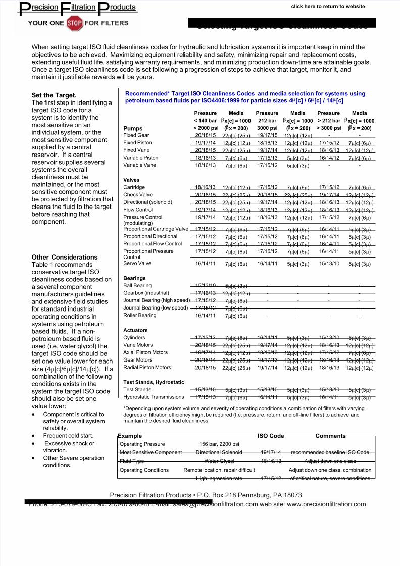
Set the Target. The first step in identifying a target ISO code for a system is to identify the most sensitive on an individual system, or the most sensitive component supplied by a central reservoir. If a central reservoir supplies several systems the overall cleanliness must be maintained, or the most sensitive component must be protected by filtration that cleans the fluid to the target before reaching that component. Selecting Target ISO Cleanliness Codes When setting target ISO fluid cleanliness codes for hydraulic and lubrication systems it is important keep in mind the objectives to be achieved. Maximizing equipment rel iability and safety, mini mizing repair and replacement costs, extending useful fluid life, satisfying warranty requirements, and minimizing production down-time are attainable goals. Once a target ISO cleanliness code is set following a progression of steps to achieve that target, monitor it, and maintain it justifiable rewards will be yours. Pressure Media Pressure Media Pressure Media < 140 bar x[c] = 1000 212 bar x[c] = 1000 > 212 bar x[c] = 1000 Pumps < 2000 psi ( x = 200) 3000 psi ( x = 200) > 3000 psi ( x = 200) Fixed Gear 20/18/15 22µ[c] (25µ) 19/17/15 12µ[c] (12µ) - - Fixed Piston 19/17/14 12µ[c] (12µ) 18/16/13 12µ[c] (12µ) 17/15/12 7µ[c] (6µ) Fixed Vane 20/18/15 22µ[c] (25µ) 19/17/14 12µ[c] (12µ) 18/16/13 12µ[c] (12µ) Variable Piston 18/16/13 7µ[c] (6µ) 17/15/13 5µ[c] (3µ) 16/14/12 7µ[c] (6µ) Variable Vane 18/16/13 7µ[c] (6µ) 17/15/12 5µ[c] (3µ) - - Valves Cartridge 18/16/13 12µ[c] (12µ) 17/15/12 7µ[c] (6µ) 17/15/12 7µ[c] (6µ) Check Valve 20/18/15 22µ[c] (25µ) 20/18/15 22µ[c] (25µ) 19/17/14 12µ[c] (12µ) Directional (solenoid) 20/18/15 22µ[c] (25µ) 19/17/14 12µ[c] (12µ) 18/16/13 12µ[c] (12µ) Flow Control 19/17/14 12µ[c] (12µ) 18/16/13 12µ[c] (12µ) 18/16/13 12µ[c] (12µ) Pressure Control (modulating) 19/17/14 12µ[c] (12µ) 18/16/13 12µ[c] (12µ) 17/15/12 7µ[c] (6µ) Proportional Cartridge Valve 17/15/12 7µ[c] (6µ) 17/15/12 7µ[c] (6µ) 16/14/11 5µ[c] (3µ) Proportional Directional 17/15/12 7µ[c] (6µ) 17/15/12 7µ[c] (6µ) 16/14/11 5µ[c] (3µ) Proportional Flow Control 17/15/12 7µ[c] (6µ) 17/15/12 7µ[c] (6µ) 16/14/11 5µ[c] (3µ) Proportional Pressure Control 17/15/12 7µ[c] (6µ) 17/15/12 7µ[c] (6µ) 16/14/11 5µ[c] (3µ) Servo Valve 16/14/11 7µ[c] (6µ) 16/14/11 5µ[c] (3µ) 15/13/10 5µ[c] (3µ) Bearings Ball Bearing 15/13/10 5µ[c] (3µ) - - - - Gearbox (industrial) 17/16/13 12µ[c] (12µ) - - - - Journal Bearing (high speed) 17/15/12 7µ[c] (6µ) - - - - Journal Bearing (low speed) 17/15/12 7µ[c] (6µ) - - - - Roller Bearing 16/14/11 7µ[c] (6µ) - - - - Actuators Cylinders 17/15/12 7µ[c] (6µ) 16/14/11 5µ[c] (3µ) 15/13/10 5µ[c] (3µ) Vane Motors 20/18/15 22µ[c] (25µ) 19/17/14 12µ[c] (12µ) 18/16/13 12µ[c] (12µ) Axial Piston Mo tors 19/17/14 12µ[c] (12µ) 18/16/13 12µ[c] (12µ) 17/15/12 7µ[c] (6µ) Gear Motors 20/18/14 22µ[c] (25µ) 19/17/13 12µ[c] (12µ) 18/16/13 12µ[c] (12µ) Radial Piston Motors 20/18/15 22µ[c] (25µ) 19/17/14 12µ[c] (12µ) 18/16/13 12µ[c] (12µ) Test Stands, Hydrostatic Test Stands 15/13/10 5µ[c] (3µ) 15/13/10 5µ[c] (3µ) 15/13/10 5µ[c] (3µ) Hydrostatic Transmissions 17/15/13 7µ[c] (6µ) 16/14/11 5µ[c] (3µ) 16/14/11 5µ[c] (3µ) Recommended* Target IS O Cleanliness Codes and media selection for sy stems using petroleum based fluids per ISO4406:1999 for particle sizes 4 [c] / 6 [c] / 14 [c] Other Considerations Table 1 recommends conservative target ISO cleanliness codes based on a several component manufacturers guidelines and extensive field studies for standard industrial operating conditions in systems using petroleum based flui ds. If a non- petroleum based fluid is used (i.e. water glycol) the target ISO code should be set one value lower for each size (4µ[c]/6µ[c]/14µ[c]). If a combination of the following conditions exists in the system the target ISO code should also be set one value lower: • Component is critical to safety or overall system reliability. • Frequent cold start. • Excessive shock or vibration. • Other Severe operation conditions. Example ISO Code Comments Operating Pressure 156 bar, 2200 psi Most Sensitive Component Directional Solenoid 19/17/14 recommended baseline ISO Code Fluid Type Water Glycol 18/16/13 Adjust down one class Operating Conditions Remote location, repair difficult Adjust down one class, combination High ingression rate 17/15/12 of critical nature, severe conditions *Depending upon system volume and severity of operating conditions a combination of filters with varying degrees of filtration efficiency might be required (I.e. pressure, return, and off-line filters) to achieve and maintain the desired fluid cleanliness. click here to return to website Precision Filtration Products • P.O. Box 218 Pennsburg, PA 18073 Phone: 215-679-6645 Fax: 215-679-6648 E-mail: sales@precisionfiltrati on.com web site: www.precisionf iltration.com
-
Upload
raghavendra-deshpande -
Category
Documents
-
view
243 -
download
0
Transcript of Target ISO Cleanliness Codes
7/27/2019 Target ISO Cleanliness Codes
http://slidepdf.com/reader/full/target-iso-cleanliness-codes 1/4
Set the Target.The first step in identifying atarget ISO code for asystem is to identify themost sensitive on anindividual system, or themost sensitive componentsupplied by a centralreservoir. If a centralreservoir supplies severalsystems the overallcleanliness must bemaintained, or the mostsensitive component must
be protected by filtration thatcleans the fluid to the targetbefore reaching thatcomponent.
Selecting Target ISO Cleanliness Codes
When setting target ISO fluid cleanliness codes for hydraulic and lubrication systems it is important keep in mind theobjectives to be achieved. Maximizing equipment reliability and safety, minimizing repair and replacement costs,extending useful fluid life, satisfying warranty requirements, and minimizing production down-time are attainable goals.Once a target ISO cleanliness code is set following a progression of steps to achieve that target, monitor it, andmaintain it justifiable rewards will be yours.
Pressure Media Pressure Media Pressure Media
< 140 bar βx[c] = 1000 212 bar βx[c] = 1000 > 212 bar βx[c] = 1000
Pumps < 2000 psi (βx = 200) 3000 psi (βx = 200) > 3000 psi (βx = 200)
Fixed Gear 20/18/15 22µ[c] (25µ) 19/17/15 12µ[c] (12µ) - -
Fixed Piston 19/17/14 12µ[c] (12µ) 18/16/13 12µ[c] (12µ) 17/15/12 7µ[c] (6µ)
Fixed Vane 20/18/15 22µ[c] (25µ) 19/17/14 12µ[c] (12µ) 18/16/13 12µ[c] (12µ)
Variable Piston 18/16/13 7µ[c] (6µ) 17/15/13 5µ[c] (3µ) 16/14/12 7µ[c] (6µ)
Variable Vane 18/16/13 7µ[c] (6µ) 17/15/12 5µ[c] (3µ) - -
Valves
Cartridge 18/16/13 12µ[c] (12µ) 17/15/12 7µ[c] (6µ) 17/15/12 7µ[c] (6µ)
Check Valve 20/18/15 22µ[c] (25µ) 20/18/15 22µ[c] (25µ) 19/17/14 12µ[c] (12µ)
Directional (solenoid) 20/18/15 22µ[c] (25µ) 19/17/14 12µ[c] (12µ) 18/16/13 12µ[c] (12µ) Flow Control 19/17/14 12µ[c] (12µ) 18/16/13 12µ[c] (12µ) 18/16/13 12µ[c] (12µ)
Pressure Control(modulating)
19/17/14 12µ[c] (12µ) 18/16/13 12µ[c] (12µ) 17/15/12 7µ[c] (6µ)
Proportional Cartridge Valve 17/15/12 7µ[c] (6µ) 17/15/12 7µ[c] (6µ) 16/14/11 5µ[c] (3µ)
Proportional Directional 17/15/12 7µ[c] (6µ) 17/15/12 7µ[c] (6µ) 16/14/11 5µ[c] (3µ)
Proportional Flow Control 17/15/12 7µ[c] (6µ) 17/15/12 7µ[c] (6µ) 16/14/11 5µ[c] (3µ)
Proportional PressureControl
17/15/12 7µ[c] (6µ) 17/15/12 7µ[c] (6µ) 16/14/11 5µ[c] (3µ)
Servo Valve 16/14/11 7µ[c] (6µ) 16/14/11 5µ[c] (3µ) 15/13/10 5µ[c] (3µ)
Bearings
Ball Bearing 15/13/10 5µ[c] (3µ) - - - -
Gearbox (industrial) 17/16/13 12µ[c] (12µ) - - - -
Journal Bearing (high speed) 17/15/12 7µ[c] (6µ) - - - -
Journal Bearing (low speed) 17/15/12 7µ[c] (6µ) - - - -
Roller Bearing 16/14/11 7µ[c] (6µ) - - - -
Actuators
Cylinders 17/15/12 7µ[c] (6µ) 16/14/11 5µ[c] (3µ) 15/13/10 5µ[c] (3µ)
Vane Motors 20/18/15 22µ[c] (25µ) 19/17/14 12µ[c] (12µ) 18/16/13 12µ[c] (12µ)
Axial Piston Motors 19/17/14 12µ[c] (12µ) 18/16/13 12µ[c] (12µ) 17/15/12 7µ[c] (6µ)
Gear Motors 20/18/14 22µ[c] (25µ) 19/17/13 12µ[c] (12µ) 18/16/13 12µ[c] (12µ)
Radial Piston Motors 20/18/15 22µ[c] (25µ) 19/17/14 12µ[c] (12µ) 18/16/13 12µ[c] (12µ)
Test Stands, Hydrostatic
Test Stands 15/13/10 5µ[c] (3µ) 15/13/10 5µ[c] (3µ) 15/13/10 5µ[c] (3µ)
Hydrostatic Transmissions 17/15/13 7µ[c] (6µ) 16/14/11 5µ[c] (3µ) 16/14/11 5µ[c] (3µ)
Recommended* Target ISO Cleanliness Codes and media selection for systems using
petroleum based fluids per ISO4406:1999 for particle sizes 4µ[c] / 6µ[c] / 14µ[c]
Other ConsiderationsTable 1 recommendsconservative target ISOcleanliness codes based ona several componentmanufacturers guidelinesand extensive field studiesfor standard industrialoperating conditions insystems using petroleumbased fluids. If a non-petroleum based fluid isused (i.e. water glycol) thetarget ISO code should beset one value lower for each
size (4µ[c]/6µ[c]/14µ[c]). If acombination of the followingconditions exists in thesystem the target ISO code
should also be set onevalue lower:
• Component is critical to
safety or overall systemreliability.
• Frequent cold start.
• Excessive shock or
vibration.
• Other Severe operationconditions.
Example ISO Code Comments
Operating Pressure 156 bar, 2200 psi
Most Sensitive Component Directional Solenoid 19/17/14 recommended baseline ISO Code
Fluid Type Water Glycol 18/16/13 Adjust down one class
Operating Conditions Remote location, repair difficult Adjust down one class, combination
High ingression rate 17/15/12 of critical nature, severe conditions
*Depending upon system volume and severity of operating conditions a combination of filters with varyingdegrees of filtration efficiency might be required (I.e. pressure, return, and off-line filters) to achieve andmaintain the desired fluid cleanliness.
click here to return to website
Precision Filtration Products • P.O. Box 218 Pennsburg, PA 18073Phone: 215-679-6645 Fax: 215-679-6648 E-mail: [email protected] web site: www.precisionfiltration.com
7/27/2019 Target ISO Cleanliness Codes
http://slidepdf.com/reader/full/target-iso-cleanliness-codes 2/4
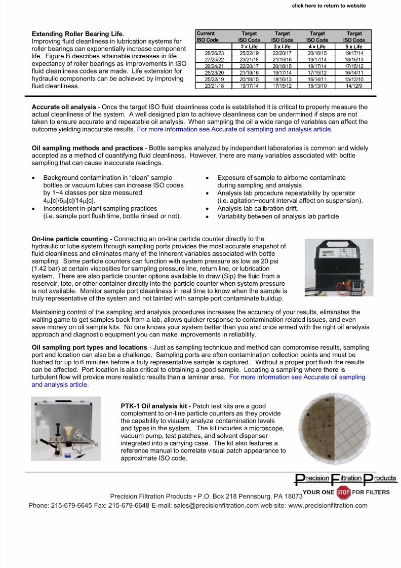
Current Target Target Target Target
ISO Code ISO Code ISO Code ISO Code ISO Code
2 x Life 3 x Life 4 x Life 5 x Life
28/26/23 25/22/19 22/20/17 20/18/15 19/17/14
27/25/22 23/21/18 21/19/16 19/17/14 18/16/13
26/24/21 22/20/17 20/18/15 19/17/14 17/15/12
25/23/20 21/19/16 19/17/14 17/15/12 16/14/11
25/22/19 20/18/15 18/16/13 16/14/11 15/13/10
23/21/18 19/17/14 17/15/12 15/13/10 14/12/9
Accurate oil analysis - Once the target ISO fluid cleanliness code is established it is critical to properly measure theactual cleanliness of the system. A well designed plan to achieve cleanliness can be undermined if steps are nottaken to ensure accurate and repeatable oil analysis. When sampling the oil a wide range of variables can affect theoutcome yielding inaccurate results. For more information see Accurate oil sampling and analysis article.
Extending Roller Bearing Life.Improving fluid cleanliness in lubrication systems for roller bearings can exponentially increase componentlife. Figure B describes attainable increases in lifeexpectancy of roller bearings as improvements in ISOfluid cleanliness codes are made. Life extension for hydraulic components can be achieved by improvingfluid cleanliness.
Oil sampling methods and practices - Bottle samples analyzed by independent laboratories is common and widelyaccepted as a method of quantifying fluid cleanliness. However, there are many variables associated with bottlesampling that can cause inaccurate readings.
• Background contamination in “clean” samplebottles or vacuum tubes can increase ISO codesby 1~4 classes per size measured,
4µ[c]/6µ[c]/14µ[c].• Inconsistent in-plant sampling practices
(i.e. sample port flush time, bottle rinsed or not).
• Exposure of sample to airborne contaminateduring sampling and analysis
• Analysis lab procedure repeatability by operator
(i.e. agitation~count interval affect on suspension).• Analysis lab calibration drift.
• Variability between oil analysis lab particle
Oil sampling port types and locations - Just as sampling technique and method can compromise results, samplingport and location can also be a challenge. Sampling ports are often contamination collection points and must beflushed for up to 6 minutes before a truly representative sample is captured. Without a proper port flush the resultscan be affected. Port location is also critical to obtaining a good sample. Locating a sampling where there isturbulent flow will provide more realistic results than a laminar area. For more information see Accurate oil samplingand analysis article.
On-line particle counting - Connecting an on-line particle counter directly to thehydraulic or lube system through sampling ports provides the most accurate snapshot of fluid cleanliness and eliminates many of the inherent variables associated with bottlesampling. Some particle counters can function with system pressure as low as 20 psi(1.42 bar) at certain viscosities for sampling pressure line, return line, or lubricationsystem. There are also particle counter options available to draw (Sip) the fluid from areservoir, tote, or other container directly into the particle counter when system pressureis not available. Monitor sample port cleanliness in real time to know when the sample is
truly representative of the system and not tainted with sample port contaminate buildup.
Maintaining control of the sampling and analysis procedures increases the accuracy of your results, eliminates thewaiting game to get samples back from a lab, allows quicker response to contamination related issues, and evensave money on oil sample kits. No one knows your system better than you and once armed with the right oil analysisapproach and diagnostic equipment you can make improvements in reliability.
PTK-1 Oil analysis kit - Patch test kits are a goodcomplement to on-line particle counters as they providethe capability to visually analyze contamination levelsand types in the system. The kit includes a microscope,vacuum pump, test patches, and solvent dispenser integrated into a carrying case. The kit also features areference manual to correlate visual patch appearance toapproximate ISO code.
click here to return to website
Precision Filtration Products • P.O. Box 218 Pennsburg, PA 18073Phone: 215-679-6645 Fax: 215-679-6648 E-mail: [email protected] web site: www.precisionfiltration.com
7/27/2019 Target ISO Cleanliness Codes
http://slidepdf.com/reader/full/target-iso-cleanliness-codes 3/4
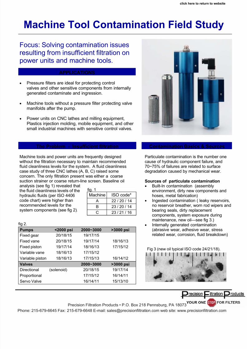
• Pressure filters are ideal for protecting controlvalves and other sensitive components from internallygenerated contaminate and ingression.
• Machine tools without a pressure filter protecting valvemanifolds after the pump.
• Power units on CNC lathes and milling equipment,
Plastics injection molding, mobile equipment, and other small industrial machines with sensitive control valves.
Focus: Solving contamination issuesresulting from insufficient filtration on
power units and machine tools.
Machine Tool Contamination Field Study
The Problem - Insufficient filtration
APPLICATIONS
Machine tools and power units are frequently designedwithout the filtration necessary to maintain recommendedfluid cleanliness levels for the system. A fluid cleanlinesscase study of three CNC lathes (A, B, C) raised someconcern. The only filtration present was either a coarsesuction strainer or coarse return-line screen. Baseline oilanalysis (see fig 1) revealed thatthe fluid cleanliness levels of thehydraulic fluids (per ISO 4406code chart) were higher thanrecommended levels for thesystem components (see fig 2).
fig. 1
Machine ISO code*
A 22 / 20 / 14
B 23 / 20 / 14
C 23 / 21 / 16
fig 2.
Pumps <2000 psi 2000~3000 >3000 psi
Fixed gear 20/18/15 19/17/15
Fixed vane 20/18/15 19/17/14 18/16/13
Fixed piston 19/17/14 18/16/13 17/15/12
Variable vane 18/16/13 17/15/12
Variable piston 18/16/13 17/15/13 16/14/12
Valves 2000~3000 >3000 psi
Directional (solenoid) 20/18/15 19/17/14
Proportional 17/15/12 16/14/11
Servo Valve 16/14/11 15/13/10
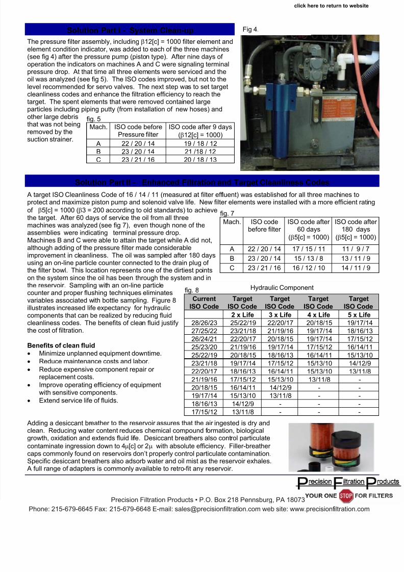
Contamination Basics & Sources Particulate contamination is the number onecause of hydraulic component failure, and70~75% of failures are related to surfacedegradation caused by mechanical wear.
Sources of particulate contamination• Built-In contamination (assembly
environment, dirty new components andhoses, metal fabrication)
• Ingested contamination ( leaky reservoirs,no reservoir breather, worn rod wipers andbearing seals, dirty replacementcomponents, system exposure duringmaintenance, new oil—see fig 3.)
• Internally generated contamination(abrasive wear, adhesive wear, stressrelated wear, corrosion, fluid breakdown)
Fig 3 (new oil typical ISO code 24/21/18).
click here to return to website
Precision Filtration Products • P.O. Box 218 Pennsburg, PA 18073Phone: 215-679-6645 Fax: 215-679-6648 E-mail: [email protected] web site: www.precisionfiltration.com
7/27/2019 Target ISO Cleanliness Codes
http://slidepdf.com/reader/full/target-iso-cleanliness-codes 4/4
Solution Part I - System Clean-up
The pressure filter assembly, including β12[c] = 1000 filter element andelement condition indicator, was added to each of the three machines(see fig 4) after the pressure pump (piston type). After nine days of operation the indicators on machines A and C were signaling terminalpressure drop. At that time all three elements were serviced and theoil was analyzed (see fig 5). The ISO codes improved, but not to thelevel recommended for servo valves. The next step was to set targetcleanliness codes and enhance the filtration efficiency to reach the
target. The spent elements that were removed contained largeparticles including piping putty (from installation of new hoses) andother large debristhat was not beingremoved by thesuction strainer.
fig. 5
Mach. ISO code beforePressure filter
ISO code after 9 days
(β12[c] = 1000)
A 22 / 20 / 14 19 / 18 / 12
B 23 / 20 / 14 21 /18 / 12
C 23 / 21 / 16 20 / 18 / 13
A target ISO Cleanliness Code of 16 / 14 / 11 (measured at filter effluent) was established for all three machines to
protect and maximize piston pump and solenoid valve life. New filter elements were installed with a more efficient ratingof β5[c] = 1000 (β3 = 200 according to old standards) to achievethe target. After 60 days of service the oil from all threemachines was analyzed (see fig 7), even though none of theassemblies were indicating terminal pressure drop.Machines B and C were able to attain the target while A did not,although adding of the pressure filter made considerableimprovement in cleanliness. The oil was sampled after 180 daysusing an on-line particle counter connected to the drain plug of the filter bowl. This location represents one of the dirtiest pointson the system since the oil has been through the system and inthe reservoir. Sampling with an on-line particlecounter and proper flushing techniques eliminates
variables associated with bottle sampling. Figure 8illustrates increased life expectancy for hydrauliccomponents that can be realized by reducing fluidcleanliness codes. The benefits of clean fluid justifythe cost of filtration.
Benefits of clean fluid
• Minimize unplanned equipment downtime.
• Reduce maintenance costs and labor.
• Reduce expensive component repair or replacement costs.
• Improve operating efficiency of equipmentwith sensitive components.
• Extend service life of fluids.
Adding a desiccant breather to the reservoir assures that the air ingested is dry andclean. Reducing water content reduces chemical compound formation, biologicalgrowth, oxidation and extends fluid life. Desiccant breathers also control particulate
contaminate ingression down to 4µ[c] or 2µ with absolute efficiency. Filler-breather caps commonly found on reservoirs don’t properly control particulate contamination.Specific desiccant breathers also adsorb water and oil mist as the reservoir exhales.
A full range of adapters is commonly available to retro-fit any reservoir.
Solution Part II - Enhanced Filtration and Target Cleanliness Codes
fig. 7
Mach. ISO codebefore filter
ISO code after 60 days
(β5[c] = 1000)
ISO code after 180 days
(β5[c] = 1000)
A 22 / 20 / 14 17 / 15 / 11 11 / 9 / 7
B 23 / 20 / 14 15 / 13 / 8 13 / 11 / 9
C 23 / 21 / 16 16 / 12 / 10 14 / 11 / 9
fig. 8
Current Target Target Target TargetISO Code ISO Code ISO Code ISO Code ISO Code
2 x Life 3 x Life 4 x Life 5 x Life
28/26/23 25/22/19 22/20/17 20/18/15 19/17/14
27/25/22 23/21/18 21/19/16 19/17/14 18/16/13
26/24/21 22/20/17 20/18/15 19/17/14 17/15/12
25/23/20 21/19/16 19/17/14 17/15/12 16/14/11
25/22/19 20/18/15 18/16/13 16/14/11 15/13/10
23/21/18 19/17/14 17/15/12 15/13/10 14/12/9
22/20/17 18/16/13 16/14/11 15/13/10 13/11/8
21/19/16 17/15/12 15/13/10 13/11/8 -
20/18/15 16/14/11 14/12/9 - -
19/17/14 15/13/10 13/11/8 - -
18/16/13 14/12/9 - - -
17/15/12 13/11/8 - - -
Fig 4.
Hydraulic Component
click here to return to website
Precision Filtration Products • P.O. Box 218 Pennsburg, PA 18073Phone: 215-679-6645 Fax: 215-679-6648 E-mail: [email protected] web site: www.precisionfiltration.com


