Target definition (margin selection) for radiotherapy (IMRT
13
1 Target definition (margin selection) for radiotherapy (IMRT) James Balter, Ph.D. University of Michigan Department of Radiation Oncology DISCLAIMER • Member, Scientific Advisory Board, Calypso Medical Issues of margin selection • Key uncertainties exist in: – Defining tumor extent – Appreciating the range and impact of geometric variation Defining the Target • Proper CTV definition remains one of the most open (target-rich?) research areas in conformal radiotherapy/IMRT • Lots of tools (PET, MRI/S, CT,US,…), but little truth • Proper consideration of patient models helps minimize error in GTV definition CTV definition references are scarce Most definitive summary: Cancer / Radiotherapie Volume 5, Issue 5, Pages 471-719 (October 2001) Volume tumoral macroscopique (GTV) et volume–cible anatomoclinique (CTV) en radiothérapie G. Kantor 1 , J. J. Mazeron 2 , F. Mornex 3 and P. Maingon 4 One minor difficulty: Ce numéro spécial de Cancer/Radiothérapie constitue une première mise au point francophone sur la définition du volume tumoral macroscopique (GTV) et du volume–cible anatomoclinique (CTV) pour les principales localisations tumorales prises en charge en radiothérapie externe et en curiethérapie. Les rapports ICRU 50 et plus récemment 62 individualisent d'une part les volumes qui relèvent de la maladie (GTV et CTV) ….
Transcript of Target definition (margin selection) for radiotherapy (IMRT
1
Target definition (margin selection) for radiotherapy (IMRT)
James Balter, Ph.D.University of Michigan
Department of Radiation Oncology
DISCLAIMER
• Member, Scientific Advisory Board, Calypso Medical
Issues of margin selection
• Key uncertainties exist in:– Defining tumor extent– Appreciating the range and impact of geometric
variation
Defining the Target
• Proper CTV definition remains one of the most open (target-rich?) research areas in conformal radiotherapy/IMRT
• Lots of tools (PET, MRI/S, CT,US,…), but little truth
• Proper consideration of patient models helps minimize error in GTV definition
CTV definition references are scarce
Most definitive summary:
Cancer / Radiotherapie Volume 5, Issue 5, Pages 471-719 (October 2001)
Volume tumoral macroscopique (GTV) et volume–cible anatomoclinique (CTV) en radiothérapie G. Kantor1, J. J. Mazeron2, F. Mornex3 and P. Maingon4
One minor difficulty:Ce numéro spécial de Cancer/Radiothérapie constitue une première mise au point francophone sur ladéfinition du volume tumoral macroscopique (GTV) etdu volume–cible anatomoclinique (CTV) pour lesprincipales localisations tumorales prises en charge enradiothérapie externe et en curiethérapie. Les rapports ICRU 50 et plus récemment 62 individualisent d'unepart les volumes qui relèvent de la maladie (GTV et CTV) ….
2
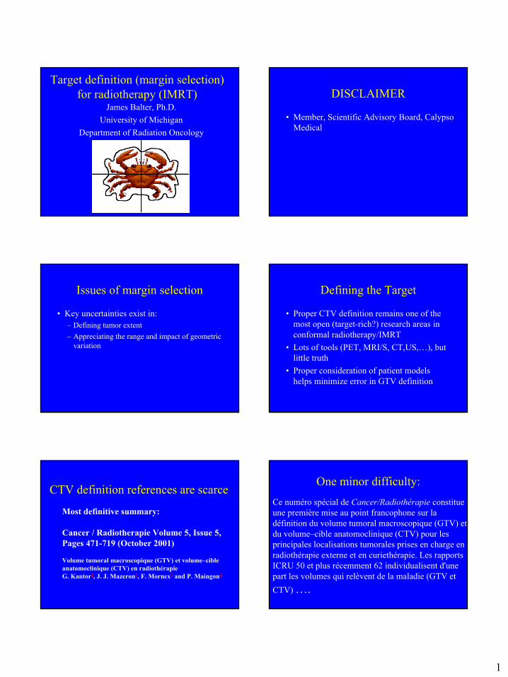
CTV definition – a dynamic field• Significant research effort in imaging will
impact CTV definition• To date, however, little is understood about
combining information from PET, MRI, MRS,…
• Pathologists are always right!
The “process” of radiotherapyEstablish Patient Model
(imaging, volume definitions, margins)
Define plan directives(target dose, normal tissue constraints,…)
Develop a treatment plan(optimization or forward planning)
Plan implementation(data transfer, DRRs, scripting,…)
Treatment verification
Scope of the problem
• Proper patient setup remains an important element of the radiotherapy QA process
• Unrecognized positioning errors are a clear point of target coverage failure for conformal radiotherapy
• Excessive margins to ensure target coverage increase risk to normal tissues
• IMRT makes these problems more acute
Patient models for optimization
• Patient modeling and/or dose calculation during IMRT planning should consider the range of possible representations of the patient expected to be realized during treatment
• Treatment verification strategies that minimize and characterize residual movement help make this problem tractable
Modeling the moving patient• A single, free breathing CT scan may be a poor
representation of the patient at any state• Example model improvements:
– Single (liver) breath-held CT at exhale, with margin for inhale
– Inhale and exhale breath held scans with free breathing (20 mA) scan for DRR (lung)
– ABC-aided CT scans– “slow” scanning – rotation times approximating a 4
second breathing cycle– “4D” CT
0
0.2
0.4
0.6
0.8
1
1.2
1.4
1.6
1.8
2
2.2
0.0 0.1 0.2 0.3 0.4 0.5 0.6 0.7 0.8 0.9 1.0
Bias towards exhale (liver)• Population-measured time course of breathing
indicates more time spent near the the exhale state (Lujan ’99)
Exhale
Inhale
Time Weight
Relative Time
Bre
athi
ng P
ositi
on [c
m]
3
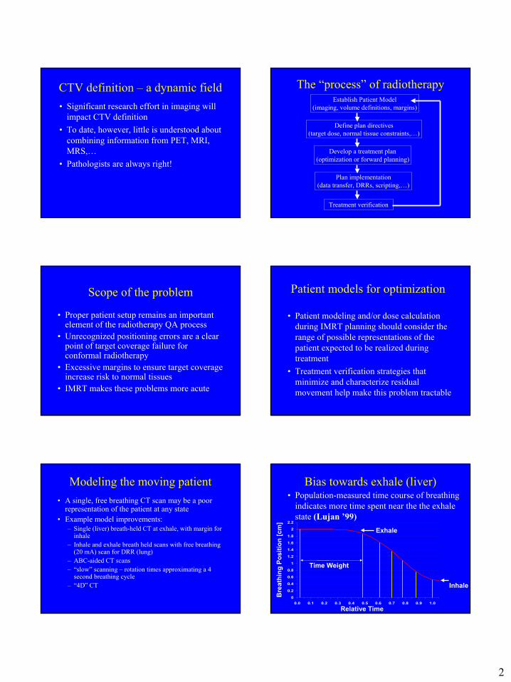
Lung “triple scan”Exhale Inhale
Free breathing (20 mA,1 or 3 mm)
Tumor definition
• “Moving GTV” constructed by compositing inhale, exhale GTV structures (with connection for space traversed if needed)
• Resulting target different from free-breathing CT and standard margins
Green – PTV from inhale,exhaleWhite – PTV from free-breathing CT + 1 cm
4D CT (movie from Dan Low, Wash. U.)
ICRU Report 62: Prescribing, Recording and Reporting Photon Beam Therapy
(Supplement to ICRU Report 50)
André Wambersie (*) and Torsten Landberg (**)
(*) Université Catholique de Louvain, CliniquesUniversitaires St-Luc, 1200 Brussels, Belgium
(**) Universitetssjukhuset, 205 02 Malmö, Sweden
ICRU 62 definitions
• GTV, CTV, PTV still exist• New definitions
– ITV (internal target volume) – expansion of CTV for internal (e.g. breathing) movement
– OR (organ at risk)– PRV (planning organ at risk volume) –
expansion of OR for movement (problematic!)
4
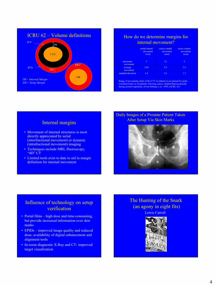
ICRU 62 – Volume definitions
CTV
IMITV
PTV
OR
PRVSM
IM = Internal MarginSM = Setup Margin
How do we determine margins for internal movement?
Range of movements (mm) of the CTV in relation to an internal fix-point (vertebral body) in 20 patients with lung cancer, studied fluoroscopically during normal respiration. (From Ekberg et al., 1998.) (ICRU 62)
1.32.61.4standard deviation
2.43.92.04average movement
5125maximum movement
dorso-ventral movement
(mm)
cranio-caudal movement
(mm)
medio-lateral movement
(mm)
Internal margins
• Movement of internal structures is most directly appreciated by serial (interfractional movement) or dynamic (intrafractional movement) imaging
• Techniques include MRI, fluoroscopy, “4D” CT
• Limited tools exist to date to aid in margin definition for internal movement
Daily Images of a Prostate Patient Taken After Setup Via Skin Marks
Influence of technology on setup verification
• Portal films – high dose and time-consuming, but provide increased information over skin marks
• EPIDs – improved image quality and reduced dose; availability of digital enhancement and alignment tools
• In-room diagnostic X-Ray and CT- improved target visualization
The Hunting of the Snark(an agony in eight fits)
Lewis Carroll
5
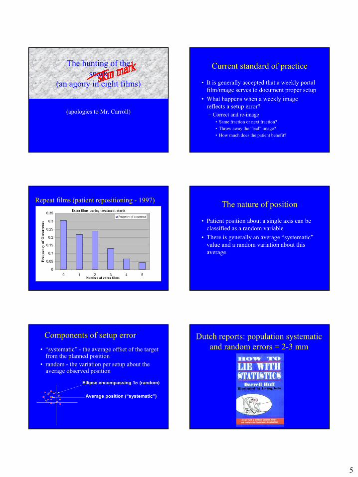
The hunting of the snark
(an agony in eight films)
(apologies to Mr. Carroll)
Current standard of practice
• It is generally accepted that a weekly portal film/image serves to document proper setup
• What happens when a weekly image reflects a setup error?– Correct and re-image
• Same fraction or next fraction?• Throw away the “bad” image?• How much does the patient benefit?
Repeat films (patient repositioning - 1997)Extra films during treatment starts
0
0.05
0.1
0.15
0.2
0.25
0.3
0.35
0 1 2 3 4 5Number of extra films
Fre
quen
cy o
f O
ccur
renc
e
Frequency of occurrence
The nature of position
• Patient position about a single axis can be classified as a random variable
• There is generally an average “systematic” value and a random variation about this average
Components of setup error• “systematic” - the average offset of the target
from the planned position• random - the variation per setup about the
average observed position
Ellipse encompassing 1σ (random)
Average position (“systematic”)
Dutch reports: population systematic and random errors = 2-3 mm
6
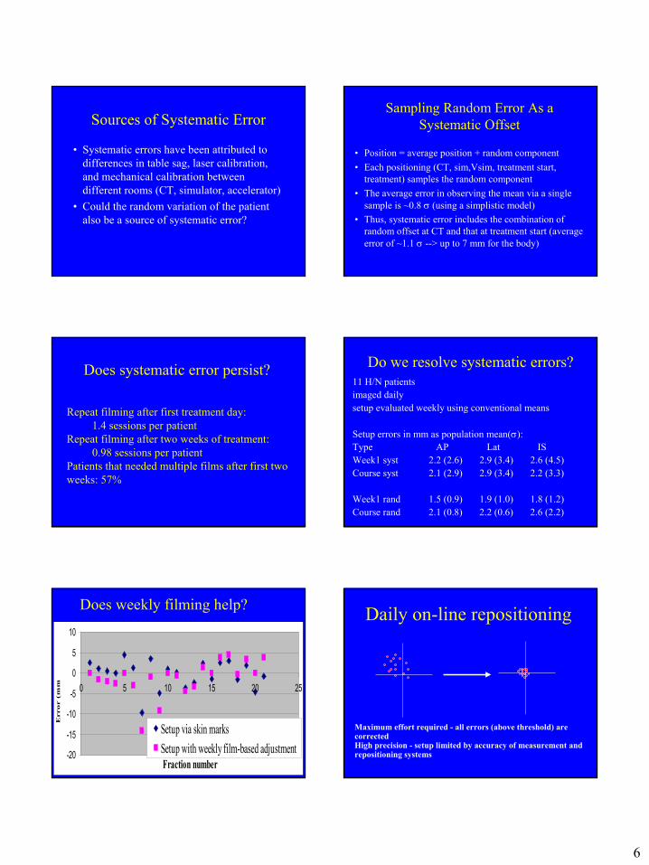
Sources of Systematic Error
• Systematic errors have been attributed to differences in table sag, laser calibration, and mechanical calibration between different rooms (CT, simulator, accelerator)
• Could the random variation of the patient also be a source of systematic error?
Sampling Random Error As a Systematic Offset
• Position = average position + random component• Each positioning (CT, sim,Vsim, treatment start,
treatment) samples the random component• The average error in observing the mean via a single
sample is ~0.8 σ (using a simplistic model)• Thus, systematic error includes the combination of
random offset at CT and that at treatment start (average error of ~1.1 σ --> up to 7 mm for the body)
Does systematic error persist?
Repeat filming after first treatment day: 1.4 sessions per patient
Repeat filming after two weeks of treatment: 0.98 sessions per patient
Patients that needed multiple films after first two weeks: 57%
Do we resolve systematic errors?11 H/N patientsimaged dailysetup evaluated weekly using conventional means
Setup errors in mm as population mean(σ):Type AP Lat ISWeek1 syst 2.2 (2.6) 2.9 (3.4) 2.6 (4.5)Course syst 2.1 (2.9) 2.9 (3.4) 2.2 (3.3)
Week1 rand 1.5 (0.9) 1.9 (1.0) 1.8 (1.2)Course rand 2.1 (0.8) 2.2 (0.6) 2.6 (2.2)
Does weekly filming help?
-20
-15
-10
-5
0
5
10
0 5 10 15 20 25
Fraction number
Error (
mm
Setup via skin marksSetup with weekly film-based adjustment
Daily on-line repositioning
Maximum effort required - all errors (above threshold) are correctedHigh precision - setup limited by accuracy of measurement and repositioning systems
7
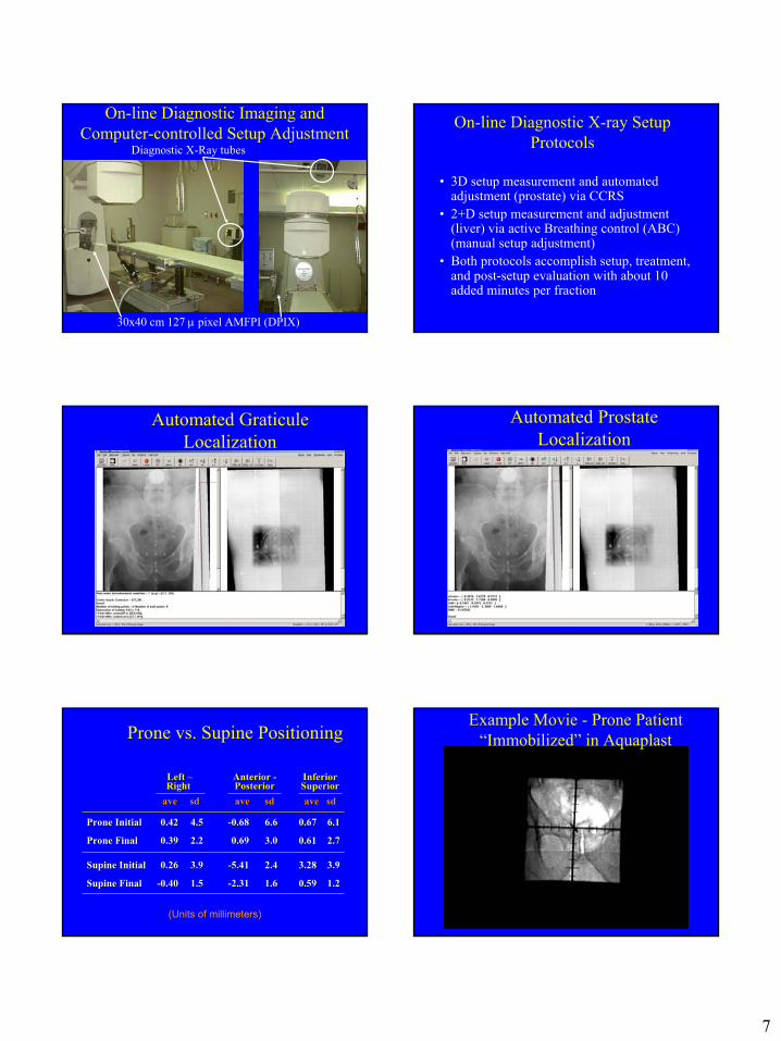
On-line Diagnostic Imaging and Computer-controlled Setup Adjustment
30x40 cm 127 µ pixel AMFPI (DPIX)
Diagnostic X-Ray tubes
On-line Diagnostic X-ray Setup Protocols
• 3D setup measurement and automated adjustment (prostate) via CCRS
• 2+D setup measurement and adjustment (liver) via active Breathing control (ABC) (manual setup adjustment)
• Both protocols accomplish setup, treatment, and post-setup evaluation with about 10 added minutes per fraction
Automated GraticuleLocalization
Automated Prostate Localization
Prone vs. Supine Positioning
Left Left ––RightRight
ave ave sdsd
Anterior Anterior --PosteriorPosteriorave ave sdsd
Inferior Inferior SuperiorSuperiorave sdave sd
Prone InitialProne Initial 0.420.42 4.54.5 --0.680.68 6.66.6 0.670.67 6.16.1
Prone FinalProne Final 0.390.39 2.22.2 0.690.69 3.03.0 0.610.61 2.72.7
Supine InitialSupine Initial 0.260.26 3.93.9 --5.415.41 2.42.4 3.283.28 3.93.9
Supine FinalSupine Final --0.400.40 1.51.5 --2.312.31 1.61.6 0.590.59 1.21.2
(Units of millimeters)
Example Movie - Prone Patient “Immobilized” in Aquaplast
8
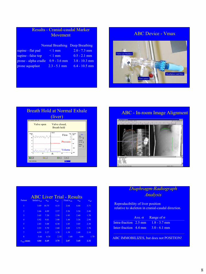
Results - Cranial-caudal Marker Movement
Normal Breathing Deep Breathingsupine - flat pad < 1 mm 2.0 - 7.3 mmsupine - false top < 1 mm 0.5 - 2.1 mmprone - alpha cradle 0.9 - 3.6 mm 3.8 - 10.3 mmprone aquaplast 2.3 - 5.1 mm 6.4 - 10.5 mm
ABC Device - Vmax
Mouthpiece and filter
Flow sensor
Valve (air bladder)
Breath Hold at Normal Exhale (liver)
Pressure
Volume
Flow
Valve closed,Breath held
Valve open
ABC - In-room Image Alignment
ABC Liver Trial - Results1 3.69 10.75 4.15 2.64 4.44 3.71
2 3.46 4.09 2.57 2.56 3.54 2.48
3 3.65 7.20 2.50 1.95 2.40 1.70
4 5.92 9.01 3.90 1.44 3.36 2.90
5 2.83 5.08 8.30 1.85 3.03 2.30
6 2.53 5.79 2.80 2.89 3.73 1.70
7 4.59 5.27 3.70 1.59 2.48 2.10
σavg (mm) 4.04 6.69 3.75 2.07 3.45 2.32
Patient Initial σLR σIS σAP Final σLR σIS σAP
8 5.66 6.34 2.10 1.68 4.66 1.70
Reproducibility of liver positionrelative to skeleton in cranial-caudal direction.
Ave. σ Range of σIntra-fraction 2.5 mm 1.8 - 3.7 mmInter-fraction 4.4 mm 3.0 - 6.1 mm
ABC IMMOBILIZES, but does not POSITION!
Diaphragm-Radiograph Analysis
Diaphragm-Radiograph Analysis
9
GATING – a word of caution
• The relationship between external markers and the tumor is inferred
• Investigators (Ford, Mageras, Vedam, Murphy) have demonstrated phase shifts between external signals and internal movement
• Some form of image-based verification is essential for gated radiotherapy
Modern EPIDS have sufficient quality for online setup adjustment
What is the true benefit of daily online adjustment?
• Van Herk determined population based margins:margin required ≅ 2.5 Σ + 0.7 σΣ – population modeled systematic errorσ – population modeled random error
Systematic error influences margin far more than random variations
Studies by other investigators support this general finding
What is the benefit of online daily repositioning?
• Except in cases of individuals with very large random variations or close proximity to critical structures, the majority of benefit in margin reduction comes not from reduction of random error, but in fact from minimization of the systematic component of setup offset
• This may be more efficiently achieved via offline or adaptive techniques of assessing setup
Off-line Observation and Systematic Error Correction
Minimum treatment delay -off-line evaluationVariable precision - limited by the random component of setup
pre-adjustmentpost-adjustment
Example of Offline correction• ~2/3 of all patients now treated at UM use offline measurement for setup correction• Setup corrected on fraction 1, followed by offline measurement through day 4 and
adjustment on day 5• Results show residual systematic errors that are removed/reduced on day 5:
Σ (Maximum) “systematic” error observed Site: lateral Anterior-Posterior Cranial-CaudalPelvis 3.1 (10.1) mm 2.5 (5.7) mm 2.6 (8.0) mmChest 3.3 (10.2) mm 3.8 (10.3) mm 3.7 (9.1) mmAbdomen 2.9 (6.9) mm 2.6 (5.8) mm 3.9 (19.1) mmH/N 2.5 (7.4) mm 2.5 (6.5) mm 3.0 (9.4) mm
These numbers are the actual positions that would have been treated without observation, and unlikely to be reduced significantly byweekly films
10
Random variationsσ (Max) (mm) (observed “random” variations)
Site: lateral Anterior-Posterior Cranial-Caudal
Pelvis 2.6 (6.2) 2.4 (6.3) 2.7 (7.0)Chest 3.0 (7.9) 2.6 (7.0) 3.4 (11.8)Abdomen 2.5 (9.1) 3.1 (9.1) 3.1 (12.4)H/N 2.1 (8.4) 2.2 (8.6) 2.7 (5.8)
Note: Measurements are from a limited number of observations per patient
Adaptive Radiation therapy (ART)•Described by Yan (Beaumont)•Typical ART implementation:
•Initiate treatment with large fields and frequent observation•Predict average offset and mean•Adjust after a few observations and reduce margin, frequency of observation•increase margin and frequency of observation if surprised by an outlier•NOTE: Given sufficiently large daily variation, Adaptive modeling selects a subset of patients for on-line localization
Adaptive Model - Example
-20.00
-15.00
-10.00
-5.00
0.00
5.00
10.00
15.00
1 2 3 4 5 6 7 8 9 10 11 12 13 14 15 16 17 18 19 20 21 22
Valu
e (m
m)
1meanst devE(m)E(s)
Advantages of ART• Potential to customize treatment to the
individual patient• Reduces the number of wasted
observations• Rapidly resolves systematic offsets
Tradeoffs
• Advantage - far higher confidence in daily positioning
• “disadvantage” - Portal images will be a more honest representation of daily setup, and thus fewer “perfect” images will be recorded
Further Obstacles to ART
• Cost – The change in paradigm requires considerations of billing / reimbursement
• Education – The concepts related to adaptive radiotherapy significantly differ from traditional training
• Infrastructure – The effort for evaluation of setup shifts away from the linac and physician workroom
11
Impact of Setup Variation
“Static” plan:Prescription doseCovers PTV
Systematic error:Shifts dose distribution(CTV still covered)
Random error:Blurs doses (highdose volumes reduce, lower dose volumes increase)
CTV
PTV
Prescription dose
Lower dose
PTV, PRV, and Setup Variations
Margins are not problematic
CTV
PTV Scriptdose
Lower dose
OAR
PRV
Overlapping margins force complicated tradeoffs in Optimization!
OAR
PRV
PTV
CTV
Accounting for Random Errors in Dose Calculations
• Convolve with a (Gaussian) kernel (Mageras, Lujan, Keall,…)
• Robust plan optimization (e.g. MIGA – Vineberg)
* =Original dose distribution
PositionDistributionkernel
Convolved dose distribution
Planning With Inclusion of Variations
CTVPTV95% dose60% dose
Traditional plan:PTV based on 0.7-1.5 σ
Plan designed with doseconvolved for setup errors
Delivered Liver Dose - Result
0
20
40
60
80
100
120
0 20 40 60 80 100 120
% dose
% v
olu
Original planTreatment with large random variationsTreatment with small random variations
12
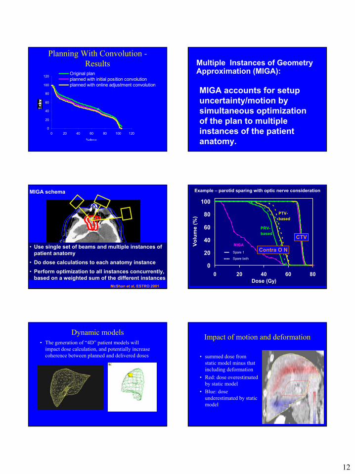
Planning With Convolution -Results
0
20
40
60
80
100
120
0 20 40 60 80 100 120
% do s e
Original planplanned with initial position convolutionplanned with online adjustment convolution
n
Multiple Instances of Geometry Approximation (MIGA):
MIGA accounts for setup uncertainty/motion by simultaneous optimization of the plan to multiple instances of the patient anatomy.
MIGA schema
• Use single set of beams and multiple instances of patient anatomy
• Do dose calculations to each anatomy instance • Perform optimization to all instances concurrently,
based on a weighted sum of the different instancesMcShan et al, ESTRO 2001
0
20
40
60
80
100
0 20 40 60 80Dose (Gy)
Volu
me
(%)
MIGA
PRV-based
PTV-based
Spare 1
Spare both
Contra O N
CTV
Example – parotid sparing with optic nerve consideration
Dynamic models• The generation of “4D” patient models will
impact dose calculation, and potentially increase coherence between planned and delivered doses
Impact of motion and deformation
• summed dose from static model minus that including deformation
• Red: dose overestimated by static model
• Blue: dose underestimated by static model
13
ICRU – dose reporting
• Level 1 – ICRU “reference point”, PTV minimum and maximum doses
• Level 2 – full 3D calculations with heterogeneity, report PTV, PRV, … volumes and dose distributions (e.g. RTOG)
• Level 3 – Currently undefined methods for dose reporting (e.g., BNCT, IMRT)
Dose prescription and reporting
• ICRU 62 requires a reference point that is in the PTV and furthermore in a region of low dose gradient
• While potentially achievable in conformable radiotherapy, IMRT via fluence optimization presents significant difficulty
• Even if the 3D dose distribution provides a homogeneous dose region, it is likely that the individual beams project steep dose gradients through the reference location
Dose reporting for organs at risk
• As shown, the delivered dose to normal tissue adjacent to the tumor may vary significantly from that planned
• Neither PRV nor OR dose volume histograms are clearly representative of expected risk (especially for parallel organs)
Summary• Margins are a difficult problem for IMRT• Given that the CTV is properly defined, treatment
planning to ensure CTV coverage can be facilitated by:- Patient modeling to reduce artifacts or unrealistic patient
models- Treatment verification strategies that understand the
patient-specific nature of setup variation- Modern developments will provide a framework to
better understand the impact of movement and setup variation to facilitate robust treatment planning