tardir/tiffs/a373403 - DTIC
58
AFRL-IF-RS-TR-1999-257 Final Technical Report January 2000 EMMA, AN EVOLUTION MEMORY MANAGEMENT ASSISTANT CoGen Tex, Inc. Sponsored by Defense Advanced Research Projects Agency DARPA Order No. D893 APPROVED FOR PUBLIC RELEASE; DISTRIBUTION UNLIMITED. The views and conclusions contained in this document are those of the authors and should not be interpreted as necessarily representing the official policies, either expressed or implied, of the Defense Advanced Research Projects Agency or the U.S. Government. 20000214 060 AIR FORCE RESEARCH LABORATORY INFORMATION DIRECTORATE ROME RESEARCH SITE ROME, NEW YORK jyjlC QUALITY DBfiPECTBD 1
Transcript of tardir/tiffs/a373403 - DTIC
AFRL-IF-RS-TR-1999-257 Final Technical Report January 2000
EMMA, AN EVOLUTION MEMORY MANAGEMENT ASSISTANT
CoGen Tex, Inc.
Sponsored by Defense Advanced Research Projects Agency DARPA Order No. D893
APPROVED FOR PUBLIC RELEASE; DISTRIBUTION UNLIMITED.
The views and conclusions contained in this document are those of the authors and should not be interpreted as necessarily representing the official policies, either expressed or implied, of the Defense Advanced Research Projects Agency or the U.S. Government.
20000214 060 AIR FORCE RESEARCH LABORATORY
INFORMATION DIRECTORATE ROME RESEARCH SITE
ROME, NEW YORK
jyjlC QUALITY DBfiPECTBD 1

This report has been reviewed by the Air Force Research Laboratory, Information Directorate, Public Affairs Office (IFOIPA) and is releasable to the National Technical Information Service (NTIS). At NTIS it will be releasable to the general public, including foreign nations.
AFRL-IF-RS-TR-1999-257 has been reviewed and is approved for publication.
APPROVED: %Lff\A 0 /Uiorti DEBORAH A. CERINO Project Engineer
FOR THE DIRECTOR:
NORTHRUP FOWLER Technical Advisor Information Technology Division
If your address has changed or if you wish to be removed from the Air Force Research Laboratory Rome Research Site mailing list, or if the addressee is no longer employed by your organization, please notify AFRL/IFTD, 525 Brooks Road, Rome, NY 13441-4505. This will assist us in maintaining a current mailing list.
Do not return copies of this report unless contractual obligations or notices on a specific document require that it be returned.
EMMA, AN EVOLUTION MEMORY MANAGEMENT ASSISTANT
Daryl McCullough Tanya Korelsky
Contractor: CoGen Tex, Inc. Contract Number: F30602-96-C-0220 Effective Date of Contract: 27 June 1996 Contract Expiration Date: 30 November 1999 Program Code Number: 6E20 Short Title of Work: EMMA, An Evolution Memory Management
Assistant Period of Work Covered: Jun 96 - Nov 99
Principal Investigator: Daryl McCullough Phone: (607) 266-0363
AFRL Project Engineer: Deborah A. Cerino Phone: (315)330-1445
APPROVED FOR PUBLIC RELEASE; DISTRIBUTION UNLIMITED.
This research was supported by the Defense Advanced Research Projects Agency of the Department of Defense and was monitored by Deborah A. Cerino, AFRL/IFTD, 525 Brooks Road, Rome, NY.

REPORT DOCUMENTATION PAGE Form Approved OMB No. 0704-0188
Public reporting burden for this collection of information is estimated to average 1 hour per response, including the time for reviewing instructions, searching existing data sources, gathering and maintaining the data needed, and completing and reviewing the collection of information. Send comments regarding this burden estimate or any other aspect of this collection of information, including suggestions for reducing this burden, to Washington Headquarters Services, Directorate for Information Operations and Reports, 1215 Jefferson Davis Highway, Suite 1204, Arlington, VA 22202-4302, and to the Office of Management and Budget, Paperwork Reduction Project (0704-0188), Washington, DC 20503.
1. AGENCY USE ONLY (Leave blank! 2. REPORT DATE
JANUARY 2000 3. REPORT TYPE AND DATES COVERED
FINAL Jun96-Nov99 4. TITLE AND SUBTITLE
EMMA, AN EVOLUTION MEMORY MANAGEMENT ASSISTANT
6. AUTHOR(S)
Daryl McCullough and Tanya Korelsky
5. FUNDING NUMBERS
C - F30602-96-C-0220 PE - 62301E, 63728F PR- D893 TA- 01 WU-01
7. PERFORMING ORGANIZATION NAME(S) AND ADDRESS(ES)
CoGen Tex, Inc. Village Green Suite 2 840 Hanshaw Road Ithaca New York 14850-1589
8. PERFORMING ORGANIZATION REPORT NUMBER
N/A
9. SPONSORING/MONITORING AGENCY NAME(S) AND ADDRESS(ES)
Defense Advanced Research Projects Agency Air Force Research Laboratory/IFTD 3701 North Fairfax Drive 525 Brooks Road Arlington VA 22203-1714 Rome New York 13441-4505
10. SPONSORING/MONITORING AGENCY REPORT NUMBER
AFRL-IF-RS-TR-1999-257
11. SUPPLEMENTARY NOTES
Air Force Research Laboratory Project Engineer: Deborah Cerino/IFTD/ (315) 330-1445
12a. DISTRIBUTION AVAILABILITY STATEMENT
APPROVED FOR PUBLIC RELEASE; DISTRIBUTION UNLIMITED. 12b. DISTRIBUTION CODE
13. ABSTRACT {Maximum 200 words!
This report summarizes the research accomplished and the resulting software tool, Evolution Memory Management Assistant (EMMA), which was developed during the contract period. The goal of EMMA is to manage information used in software development throughout a system's life cycle. EMMA differs from current project management tools in that it manages not only the system requirements that developers must satisfy, but also the context in which the developers develop the system. This contextual information includes assumptions about the operating environment and user behavior, and it supports explicit planning of software evolution. EMMA also relates system development tasks to technical issues to help ensure that all members of the project are informed about the consequence of development decisions. EMMA keeps track of dependencies among system components and also the reasons (rationale) for dependencies. Thus, EMMA is flexible in considering contingencies and alternative approaches to building a system.
14. SUBJECT TERMS
Project Management, Requirements Management 15. NUMBER OF PAGES
64 16. PRICE CODE
17. SECURITY CLASSIFICATION OF REPORT
UNCLASSIFIED
18. SECURITY CLASSIFICATION OF THIS PAGE
UNCLASSIFIED
19. SECURITY CLASSIFICATION OF ABSTRACT
UNCLASSIFIED
20. LIMITATION OF ABSTRACT
UL Standard Form 298 (Rev. 2-89) (EG) Prescribed by ANSI Std. 238.18 Designed using Perform Pro, WHS/DIOR, Oct 94

Table of Contents
INTRODUCTION 3
What is EMMA? 3
EMMA in Action 3
Initial Development 3 Maintenance 8
What Problems Does EMMA Address? 1°
How Does EMMA Represent Design Information? 1"
Features of EMMA * 1
Comparison of EMMA with Other Tools and Methodologies H EMMA and Design-by-Contract U EMMA and other information management tools 12
Conclusions and Recommendations for Future Work 17 Recommendations for Future Work 18
THE EMMA METAMODEL FOR SYSTEM EVOLUTION 20
Properties and Context 20
Goals and Solutions 22 Why Alternative Solutions? 23
Dependencies 23
Releases 24
Collaboration: Goal Owners and Contractors 25 Negotiation and Discussion among Collaborators 26
Consistency and Completeness 28 Consistency and Completeness Problems 28
BIBLIOGRAPHY 29

APPENDIX: EMMA PAGES AND COMMANDS 31
EMMA Title Page 31
Login Screen 31
Workspace Page 31 Creating a New Workspace 32 Operations on an Existing Workspace 32 Miscellaneous 33
Left Frame 33 Hide/Show Solutions 34 Lower Left 35
Right Frame 36
Tabs 37
Details Page 37 Alternatives/Subgoals Page 42 Properties Page 43 Context Page 49 Status Page 49
List of Figures
Figure 1: EMMA Solution Structure for "Status Reporter" 6 Figure 2: Completeness/Consistency Report for one property of Status Reporter 7 Figure 3: Release Report for "Status Viewer" 8 Figure 4: Analysis of Progress Reports 9

Introduction
What is EMMA?
EMMA is an innovative tool that lets developers collaboratively explore, select, and document alternative solutions to the problem of evolving a complex system to meet changing requirements.
In order to make well-informed decisions about the evolution of a system through its sequence of releases, managers need access to information about interdependencies among the requirements, constraints and for different parts of the system. EMMA provides a web-based interface for recording, managing, and disseminating this information.
EMMA in Action
In this section, we describe a scenario in which EMMA is used. To simplify things, we describe the requirements negotiation process as taking place among a single group of developers in the initial stages of a project.
Initial Development
Debbie has an idea for making a useful tool: a program that automatically generates status reports from project management data. At this stage, it is just the germ of an idea; Debbie doesn't know what the requirements ought to be, or what resources will be needed to build it, or what sorts of report format should be used, or what sort of data format the project data will be in. But, she knows enough to get started in EMMA:
• She creates a new EMMA workspace for recording development information about the system.
• She calls the top (and only) node "Status Reporter". The top node of an EMMA workspace represents the entire system to be built, while lower-level nodes represent components ofthat system.

• She makes herself the owner of this node. That means that she is the only one allowed to modify the requirements for the system as a whole.
On the properties page, she enters one item: "Automatically generates progress reports from project management data". The properties of the top node represent requirements of the system as a whole.
Before Debbie can go any further with her idea, there are many questions that need to be answered and issues to address:
1. What format will the reports be in?
2. What data format will the project data be in?
3. What technology will be used to generate the reports?
4. What platform will the report generator run on?
5. etc.
At this point, Debbie calls a brainstorming meeting of all her developers to discuss the project.
Fred suggests that, rather than developing text generation technology from scratch, they should use the Company X text generation framework. Debbie agrees, but to be a little more general, she puts "text generation framework" into the context of the top goal. The context represents assumptions as well as resources used in building the system.
Ted proposes that a quick prototype could be implemented in WordBasic using MailMerge (a simple programmable database that interoperates with MS Word) as a stand-in for a project management database. The first prototype might just use fill-in- the-blank templates to create the reports, rather than real text generation. Debbie makes Ted a contractor for the top node. (The contractors for a node are those team members that will work on implementing the system or component corresponding to that node). Underneath the top node, Ted creates a solution called "Word-based Solution". (A solution is a particular approach to building a system or system component by dividing system requirements among lower level components. Each solution will have several subgoals underneath representing these components.) On the properties page, Ted adds new properties, "Word-compatible reports" and "Able to incorporate free text in Word format". On the context page, Ted adds the resources "MS Word", "WordBasic", and "MailMerge". Ted gives the solution the following subgoals:
1. MailMerge database
2. Report templates
3. GUI Interface
4. WordBasic macros
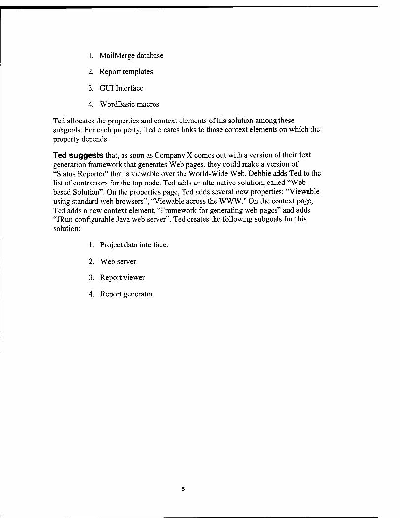
Ted allocates the properties and context elements of his solution among these subgoals. For each property, Ted creates links to those context elements on which the property depends.
Ted suggests that, as soon as Company X comes out with a version of their text generation framework that generates Web pages, they could make a version of "Status Reporter" that is viewable over the World-Wide Web. Debbie adds Ted to the list of contractors for the top node. Ted adds an alternative solution, called "Web- based Solution". On the properties page, Ted adds several new properties: "Viewable using standard web browsers", "Viewable across the WWW." On the context page, Ted adds a new context element, "Framework for generating web pages" and adds "JRun configurable Java web server". Ted creates the following subgoals for this solution:
1. Project data interface.
2. Web server
3. Report viewer
4. Report generator

Ted then allocates the properties and context elements of her solution among these subgoals. For each property, Ted creates links to those context elements on which the property depends.At this point, the EMMA solution structure for "Status Reporter" looks like Figure 1.
^ EMMA - Netscape
0e £<Ä üiew fio £omnuricatof Help
BEE
■jj. ^^
$•;*; Web-based Solution j-@ Project Data Interface j-© Web server ;■■■© Report viewer L© Report generator
B- S Word-based Solution !••■© MailMerge Database [•■•© Report templates !•■■© GUI Interface *•■■© WordSasic macros
Hide Solutions • Workspaces Releases • Undo • Redo • He
. A. <ä EMMA Saving: on. Workspace: Persic« I of Status
Reporter.
| Status Reporter
Parent Solution , Active Solution
Details Alternatives Properties | Context Status
Name Status Reporter
Owner Debbie
Contractors • Greta • Fred • Ted
Type Application
Description Generates status reports from project data.
Parent Solution (none) —
Releases • 1.0
4 0
'RBhl [Document Done
Figure 1: EMMA Solution Structure for "Status Reporter''
Debbie adds a sequence of releases and tentatively assigns properties and context elements to releases. The first release will have the properties "Generate status reports from project data", "Word-compatible reports" and "Able to incorporate free text in Word format". The second release will have the properties "Generate status reports from project data", "Viewable using standard web browsers", and "Viewable across the WWW." On the context page, Debbie assigns context elements to releases to reflect when they will likely become available.
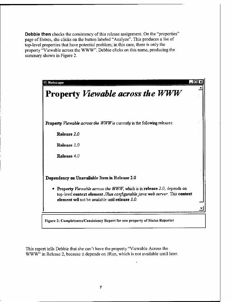
Debbie then checks the consistency of this release assignment. On the "properties' page of EMMA, she clicks on the button labeled "Analyze". This produces a list of top-level properties that have potential problem; in this case, there is only the property "Viewable across the WWW". Debbie clicks on this name, producing the summary shown in Figure 2.
i£r Netscape HEB
Property Viewable across the WWW
Property Viewable across the WWW is currently in the following releases:
Release 2.0
Release 3.0
Release 4.0
Dependency on Unavailable Item in Release 2.0
• Property Viewable across the WWW, which is in release 2.0, depends on top-level context element JBun configurable Java web server. This context element will not be available until release 3.0.
d Figure 2: Completeness/Consistency Report for one property of Status Reporter
This report tells Debbie that she can't have the property "Viewable Across the WWW" in Release 2, because it depends on JRun, which is not available until later.

To correct this problem, Debbie moves the property "Viewable Across the WWW" to release 3.
Finally, Debbie generates a summary of the release plan. The results are shown in Figure 3.
'- Release Report for Goal "Status Repoitet - Netscape
Release Report for Q| Status Reporter
Releases
1.0
2.0
3.0
New Objects in Release
(F> 'Word-compatible reports
(P) Able to incorporate free text in 'Word format
(F) Generate status reports from project data
(G) Status Reporter
(St Web-based Solution (active)
(Gt Project Data Interface
(G) Report generator
(S) Word-based Solution
(G) MaflMerge Database
(G) Report templates
(O) GUI Interface
(G) WordBasic macros
(P) Viewable using standard web browsers
(P) Viewable across the WWW
(G) Web server
(G) Report viewer
(O JRun configurable Java web server
Figure 3: Release Report for "Status Viewer"
Objects Removed from Release
(S) Word-based Solution
Release Description
Zi
Maintenance Later, development on status reporter has reached the maintenance phase. The Word based prototype has been built, and feedback was gathered. The feedback was used to

come up with new requirements (entered as properties) for the commercial, Web- based release:
• The first Web version of Status Reporter works off of ASCII data files representing the project data. A planned later version will work off of a database API instead.
• Besides status reports, which only describe the current state of the project, Debbie wants to be able to also generate progress reports, which compare the state of the project on two different months.
Debbie tentatively plans to implement progress reports in release 3.0, and to make release 4.0 database compatible. She makes these release assignments in EMMA and clicks on Analyze. The results are shown in figure 4. There is a problem in release 3.0 because progress reports depend on Project History, which is only available in the database compatible version. For this reason, Debbie decides to postpone progress reports until release 4.0 (or she could implement database compatibility earlier).
|^ Netscape HHD
Property Progress Reports A
Property Progress Reports is currently in the following releases:
Release 3.0
Release 4.0
Dependency on Unavailable Item in Release 3.0
• Property Progress Reports, which is in release 3.0, depends on property Project History Data of solution Database Compatible Interface. This solution will not be available until release 4.0.
zl
Figure 4: Analysis of Progress Reports

What Problems Does EMMA Address?
EMMA provides a combination of features that is unique among tools to support software engineering. EMMA provides a convenient structure that explicitly records the following types of information.
1. The properties that a system (or component) must fulfill and the context under which it is to be developed. This way of organizing system requirements is critical for being able to plan for the evolution of a complex system.
2. The planned sequence of releases of a system, and the information about what system properties and context elements will be available in what releases.
3. The alternative solutions considered for each system component.
These features together provide information management to support the development and evolution of a complex system. They allow for reasoning about interdependencies of subsystems and about what each member of the development team is expecting from the others. EMMA supports developers in thinking in terms of system evolution rather than the separate activities of system development and system maintenance. By explicitly representing alternatives and future releases, developers have a convenient way to record their thoughts about why they made the design decisions they made and what future circumstances would cause them to revise those decisions.
How Does EMMA Represent Design Information?
10

Design evolution information in EMMA is organized around five interrelated concepts:
• Functional requirements;
• Context: assumptions, resources and design constraints under which those requirements are to be achieved;
• Development goals, which cluster related requirements and the associated context information;
• Solutions, which are software engineering approaches to meeting those goals;
• Evolutionary Change, which may alter requirements, context, goals or solutions.
Features of EMMA
EMMA uses a Java/HTML-based hypertext interface, for easy deployment in any environment that supports standard web browsers. It also uses CoGenTex's advanced presentation generation technology to automatically generate various hypertext reports and web pages. Information entered into EMMA can include links to external documents, such as requirements or specifications created using other tools.
Comparison of EMMA with Other Tools and Methodologies
EMMA and Design-by-Contract EMMA's approach to system development by partitioning into components, each of which must satisfy certain requirements, is similar to the idea of "Design by Contract" [Meyers]. An EMMA solution structure can be thought of as a contract for building a solution and also for future evolution ofthat solution. However, Design by Contract as it is usually interpreted does not provide any mechanism for discussion and negotiation about the nature of the contract; it is a purely top-down development. The EMMA metamodel is unique in providing for exceptions, which allow for "contract negotiation" in which bottom-up influences can affect the final design for a system.
Each goal in an EMMA solution structure represents functionality that the contractor promises to provide (by building a solution). The context associated with a goal represents commitments made by the goal owner (which can reflect functionality provided by other contractors, or guarantees about the users or operating environment). This view of system development is compatible with (but not limited to) the concept of required and provided interfaces for components [Euclid, TRP,
11

CBSE]. The provided interface describes the external behavior the component must satisfy, while the required interface describes the demands the component makes on (or services required of) other components. The EMMA notion of exceptions is broader than the usual notion of required interfaces, however. Exceptions allow a component to make demands not only on other components, but also on users and on the environment. Thus in an iterative development model, some of the high-level goals for the system may ultimately reflect the needs of particular components. This is important for system developers to know, since evolutionary changes may modify or eliminate components and thus make some system requirements obsolete.
EMMA and other information management tools
The goal of EMMA is to manage information used in software development throughout a system's life cycle. EMMA differs from other tools in several respects: (1) EMMA manages not only the system requirements that developers must satisfy, but also the context in which the developers develop the system. This contextual information includes assumptions about the operating environment and user behavior of the fielded system, and also assumptions about externally supplied products (tools, infrastructure, etc.). (2) EMMA supports explicit planning of software evolution. Following the release-based software development model, EMMA allows developers to plan for several future versions of a system at once, so that the system can be built not only to satisfy current requirements, but also to anticipate future requirements. (3) EMMA supports communication among all the members of the development team, including project managers, software designers and software developers. (4) EMMA relates system development tasks to technical issues, to help make sure that all members of the project are informed about the consequences of development decisions.
EMMA has some similarities with three broad types of tools: (1) Project and process management tools, (2) Requirements management tools, and (3) Configuration management tools.
Project Management Tools
Like project management tools such as Microsoft Project, EMMA partitions work on a project into a number of smaller parts, and allocate each part to one or more members of the development team. Also like project management tools, EMMA keeps track of the dependencies among parts of a large project. However, in project management tools, the emphasis is on scheduling and resource allocation for tasks, while in EMMA the emphasis is on assumptions and requirements for system components. In project management tools, there is no convenient way to connect the various tasks with system components, and there is no way to automatically
12
determine functional dependencies among tasks; these dependencies must be inserted by hand. On the other hand, EMMA keeps track of dependencies among system components in terms of the properties and assumptions declared for each component. In this way, EMMA has a more detailed understanding not only of dependencies, but also the reasons (rationale) for dependencies. EMMA thus is more flexible in considering contingencies and alternative approaches to building a system. Because EMMA is not concerned with scheduling or with resource allocation, its functionality is complementary to that of a project management tool.
Requirements management tools
Requirements management tools such as Requisite Pro share with EMMA the concern with system requirements and collaborative information management among participants on a project. Requisite Pro supports team-based requirements management. It allows project team members to prioritize, sort, and assign responsibilities for requirements. It also provides dependencies among requirements, which can be used to trace the relationships among parts of a project (or even among different projects) and supports the computation of the impact of a change of requirements. Finally, like EMMA, Requisite Pro supports the recording of requirements changes, including who made the change, at what time, and why. While much of the functionality of Requisite Pro is similar to that of EMMA, EMMA's notion of a solution structure provides a framework for reasoning about requirements and the components built to satisfy them. Also, EMMA's notion of a sequence of releases provides a temporal dimension for reasoning about requirements that is missing in pure requirements management tools. In these ways, EMMA provides more structure on which to hang requirements and reason about them.
DOORS
DOORS [DOORS] is a requirements traceability tool which provides extensive support for managing shared structured data. Its data model is very general: information is organized into modules, each of which is a hierarchical collection of objects. Each object has a number of attributes, and structured links to other related objects. DOORS provides a convenient "drag and drop" interface for quickly making links between objects. It also provides a wealth of different options for importing and exporting structured data—as Word documents, Microsoft Project data, HTML, etc.
DOORS provides a very flexible and useful framework for collaborative recording and modifying requirements data. Unlike EMMA, DOORS does not assume any particular metamodel. Although this greatly increases the flexibility of using DOORS, it eliminates the possibility of any automated heuristic support in maintaining
13
consistency, or checking for completeness. Such automated support would have to be implemented as third-party "critic" programs that worked off of DOORS data.
One interesting possibility for future work on EMMA would be to reimplement EMMA
using DOORS. This would amount to defining a set of module types, object types, attributes and link types that would be meaningful to EMMA, and then writing all the EMMA analysis tools as various critics on the DOORS structure. Although DOORS doesn't provide any type checks or other consistency checks on its structures, it would be possible to write a report generator that created reports on problems found with a solution structure represented in DOORS.
The only thing that may be difficult to do using DOORS would be to provide interactive support for making a sensible solution structure. Of course, it can all be done after-the-fact via critics on DOORS export files. Many of the EMMA concepts are completely missing in DOORS, such as the notion of a "release", and the distinction between properties and context. But that's to be expected, since it is really a generic tool for managing shared structured data.
Another possibility would be to just keep the EMMA Java code as it is, and work on import/export from DOORS. We could probably make it so that solution structures could be created/edited in either tool.
IBIS/REMAP Whereas DOORS and RequisitePro are intended to capture structural aspects of requirements, another type of requirements management tools are for recording and managing discussions, which provide the reasoning behind design decisions. IBIS (Issue Based Information Systems) [IBIS] is a model for representing discussions such as those that a group might have prior to making a decision about a course of action. IBIS sorts the information about how such a discussion progressed into several categories of discussion objects:
1. Issue. An issue is usually a question that needs to be answered, such as "How shall we accomplish such-and-such? " Such questions are the starting points for discussions.
2. Position. A position is a proposed answer to a question, or a proposed approach to addressing an issue. For example, if the issue is "How shall we get a system with such-and-such properties?" there may be two main alternative positions: (1) "Build it" and (2) "Buy it."
3. Argument An argument is a reason for supporting or objecting to a position. For example, the position called "Buy it" may have a supporting argument "It is quicker" and may have an objecting argument "No current products have a flexible enough interface."
14

A problem with IBIS is that discussions can grow to be enormously complicated, and there is no support for relating the discussions to decisions that have been actually made in the development of a system. Partly this is because IBIS was intended to be a general model for representing discussions, and was not created with software engineering specifically in mind. REMAP (Representation and Maintenance of Process knowledge) [REMAP] is an extension to IBIS that adds new types of objects and relationships specifically to support the software development process. In addition to the objects supported by IBIS, REMAP also provides the following additional ones:
4. Requirement By introducing requirements, REMAP helps to focus discussions towards the ultimate objectives for the project.
5. Decision. While IBIS simply records the alternative positions, REMAP provides more history information about a project by also recording decisions made.
6. Constraint. REMAP explicitly records the constraints that design decisions place on the artifacts being developed.
7. Design Object REMAP also explicitly represents the system design artifacts that are at issue in discussions.
8. Assumption. REMAP makes explicit the assumptions behind arguments.
Relationship with EMMA: REMAP captures some of the same kind of information as the EMMA metamodel. In particular, REMAP is like EMMA in attempting to relate design objects to the assumptions under which those objects were designed. The main focus of REMAP is to record the reasons for deciding among alternative design artifacts. However, in REMAP the relationship between assumptions and design artifacts is indirect: Assumptions are related to arguments, which are related to decisions, which affect design artifacts. EMMA more directly records assumptions as they are relevant to a solution. In contrast to IBIS and REMAP, EMMA structures system information not around issues to be addressed, but around the goals for the system and its components. EMMA also specifically addresses evolution. We believe that this will provide a tighter structure to the information and will allow a more efficient use of the information in future evolution.
One promising approach is to combine REMAP with EMMA. EMMA would provide the overall structure that would serve to focus system information around particular system development goals. REMAP could then be for discussions leading to a decision among alternative plans in the EMMA solution structure.
15

WinWin IBIS and REMAP take discussions to be about objective, factual issues. In contrast, the WinWin model [WinWin], also funded by EDCS, recognizes that different stakeholders may have different objectives for a project and different views about what is relevant and what is important. WinWin makes the idea of negotiations among multiple stakeholders explicit in the model. The objective of a WinWin discussion is to find a set of win conditions that are acceptable to all of the diverse participants in a project.
We will not attempt to describe the WinWin model in detail, but instead will summarize the key points that are relevant for EMMA:
By keeping track of the sources for requirements (Which stakeholders demanded which requirements? To what extent were the requirements a compromise between different objectives?) WinWin can help future maintainers to understand the issues involved in system evolution. The objectives of the different stakeholders can be revisited at a later time to see if the reasons for the original development decisions still apply.
WinWin explicitly records when requirements are "scoped out" because of lack of resources or because of conflict with other requirements. System requirements that have temporarily been put to the side are good candidates for possible directions of evolution directions for the system.
EMMA has several features in common with WinWin. In particular, both systems support collaboration, recording of goals and assumptions, and recording possible directions for system evolution. However, these two systems are appropriate at different stages of a system's life cycle. WinWin is most appropriate during the initial negotiation of requirements among customers, end-users, and developers. Unlike WinWin, EMMA assumes that the developers are, in some sense, all on the "same team" and are trying to accomplish the same ultimate goals. EMMA is therefore more suited for goal-directed development after the initial requirements have stabilized and in planning for future evolution.
Configuration Management Tools
Finally, configuration management tools such as StarTeam provide functionality that is in some ways similar to that of EMMA. Like EMMA, StarTeam is a collaborative information management tool. It keeps track of differences between versions of a software product. It supports future releases indirectly, by tracking the handling of change requests. Like EMMA, StarTeam supports distributed projects. However, the emphasis of StarTeam is mainly on configuration management, and annotating versions of a software product with information about how it differs from earlier
16

versions (and why the changes were made). In contrast with EMMA, StarTeam is not concerned with planning future evolution of a system, but is instead concerned with documenting past evolution.
Conclusions and Recommendations for Future Work
The idea behind the use of EMMA to support software evolution is that when an evolutionary step occurs, it will always be initiated by some change of properties or context at some level of the solution structure. EMMA can help in understanding the impact of such a change by tracing through the dependency relationships to discover what subgoals are affected by the change. The tracing can be used in the reverse direction, as well, to find out what high-level goals depend on what components of the system solution. This makes analysis of the impact of changes much more focussed.
EMMA is designed to support system development and evolution in the following ways:
• It supports structured, goal-directed communication about system development. EMMA provides a framework for recording information about the expectations and responsibilities of all members of the development team.
EMMA presents information about the status of a development project, tailored for each subsystem or component. This status information includes incompleteness (in terms of requirements implemented) as well as inconsistencies of the dependency or release information.
EMMA provides evolution assistance in several ways:
1. It provides a mechanism for a developer to anticipate future changes in requirements, assumptions and resources, and record a plan for responding to these changes. These recorded anticipations can provide a valuable head-start for future system developers charged with responding to such changes.
2. It allows for high-level requirements or assumptions to be changed to take into account problems encountered in implementation. A developer who runs into problems in fulfilling a goal can request changes in the requirements for that goal. EMMA provides a structure for recording the reasons for such changes and provides support for propagating such changes throughout the system.
17

3. It supports release planning by providing an analysis of the completeness and consistency of a system, on a release-by-release basis. EMMA does this by tracing the chain of dependencies of features for each release to see if a property depends on a resource that is not available for the release or on a low-level property that will not be implemented for that release.
Recommendations for Future Work
Currently, EMMA exists as a research prototype. For it to be made into a useful, commercial-quality tool, there are several design, feature, and implementation changes that should be made.
Database implementation First, EMMA currently stores all information in an ASCII file format. Although this choice was convenient for rapid implementation of the prototype, it is not a viable long-term solution. Eventually, EMMA should be reimplemented using a fast, robust, database. This would have many advantages, because many of the EMMA operations that are now slow and fragile could be implemented using standard database operations. These include: (1) copying all or part of a solution structure, (2) maintaining links among properties, (3) maintaining history information and making backups, (4) multiuser operations.
Multi-Threaded Server and Improved Multi-user Capabilities The current implementation of EMMA only allows one user to access an EMMA
solution structure at a time. This limitation would be unacceptable in a big project involving a large number of developers. For this reason, the EMMA Data Manager needs to be rewritten so that several users can access EMMA at the same time. Also, the access control that is currently used by EMMA is not very robust, and easily circumvented. A more secure form of access control should replace it.
The implementation of a more sophisticated multi-threaded/multi-user version of EMMA depends on the multi-use policy that is to be enforced. For this reason, development along these lines needs to take place using extensive feedback from user groups.
Improved Reports Although EMMA currently generates a number of different types of reports about the state of the EMMA solution structure, these reports could certainly be improved greatly, to make them more focussed and more informative. As with the multi-user capability, the exact type of reports to be generated should be decided with extensive feedback from user groups.
18

Automated Support for Creating and Modifying Solution Structures The usability of EMMA would be greatly improved with more sophisticated ways to create and modify complex solution structures. The exact type of operations that should be supported would depend on the needs of user groups. This feature would also depend on the type of operations provided by the database implementation.
More Flexible Solution Structures and Releases Although the EMMA metamodel is very general, there are still serious limitations that may need to be overcome in a commercial-quality product. Some new features that would likely prove useful in the development of a complex system are:
1. Ability to create subreleases. EMMA'S current notion of a "release" is a delivery of the entire system. For a complex system, there will also be subreleases, which are different versions of components or subsystems. EMMA needs the ability to declare subreleases and specify how they combine to make releases of the system as a whole.
2. Structure sharing. Currently EMMA does not allow alternative solutions to share subgoals. It is possible to copy a goal from one solution and paste it into the other, but once that is done, changes to the original are not reflected in the copy.
3. Parallel solution development. Currently, EMMA has a linear notion of a system's releases. At any time, there is a notion of the "current release". A more general approach would be to allow multiple, ongoing versions of a system to be represented in EMMA at the same time. For example, there could be Macintosh and Windows versions of a software system which would evolve in parallel.
These changes to EMMA would make it into a unique and very powerful tool for managing the evolution of complex software systems.
19

The EMMA Metamodel for System Evolution EMMA was designed to support the collaborative development and evolution of complex systems. EMMA manages the collection "evolution memory" for a software system, which contains information about the context in which design decisions were made, including plans for future system evolution. Software developers have the opportunity both to draw from this memory to understand the reasons for past decisions and the consequences of evolutionary changes, and to add to it, to make their own insights available for future system evolution.
EMMA'S approach to supporting software evolution is to let the developers' goals for software evolution drive the way design knowledge is acquired and presented. EMMA
supports the communication and management of information about the goals and plans for system development by providing a structured interface for recording this information, and a collection of tools for analyzing the consequences of changing requirements. This chapter describes the metamodel for system evolution supported by EMMA.
Properties and Context
In designing a new system, developers need to keep in mind two different kinds of information:
1. properties of the desired system: what functionality the users of the system (where the "users" might not be human; they might be other systems) can expect the system to provide, and
2. contextual information: assumptions about users, other systems, computational infrastructure and operating environment on which the system can rely.
20

Typically, a system's requirements combine both types of information, but very oftei. much of the background information about the expected behavior of users and the properties of the operating environment is left implicit. The lack of documentation of implicit assumptions makes it very difficult to uncover the impact when this kind of information changes.
EMMA uses the term property to mean any feature or attribute that a system or system component should have when it is implemented. The assumptions, resources, and definitions of terms used in implementing the system or component are collected in the context. EMMA is unique among requirements management tools in clearly making the distinction between properties and context.
The EMMA metamodel thus explicitly distinguishes between functional requirements for the system (which become "properties") and the context within which the system is developed. The context consists of background information that is needed to understand a system's functional requirements, including:
• the definitions of terms used in the requirements,
• assumptions about the domain, users and the operational environment, and
• properties of other systems with which the system being built must interact.
The context provides a framework within which the solution is to be constructed, and describes the system's role within that framework.
In the EMMA metamodel, the context associated with a goal will include the answers to the following sorts of questions (not intended to be exhaustive):
• What sort of users will be operating the system, and what kind of training will they have?
• How many users will operate the system simultaneously?
• Into what sort of operating environment will the system be placed?
• What resources (COTS products, tools, etc.) will be used with the system being developed?
• What are the properties of those resources on which we can we rely?
• What are the meanings of the terms used in the requirements documents?
21

In understanding the design of a system, this kind of context information is as important as the functional requirements that the system must meet. This is especially true for system evolution. When putting a system into a new environment, it is crucial to understand what assumptions the original developers made about the operating environment. If some of these assumptions are no longer valid, then the system will likely need to be redesigned. EMMA'S ability to trace the assumptions to the specific system components that rely on them can greatly improve the efficiency of responding to system changes.
Goals and Solutions
The organizing principle behind EMMA'S metamodel for system development is that to reason about system evolution, it is necessary to understand in detail the goal for a system and the solution constructed to address those goals.
A goal for EMMA is a collection of properties and context elements that together describe a kind of development contract. The contractor agrees to build a system or system component satisfying the properties for that goal, if the client provides all the resources appearing in the context and insures that all the assumptions appearing in the goal's context are true.
A solution in the EMMA metamodel is a software engineering approach to satisfying some development goal. A solution may either be atomic or composite. An atomic solution is created by explicitly providing a reference to an existing implementation satisfying the goal (e.g., a COTS tool or component from a library). A composite solution describes a way of creating a system by partitioning system responsibilities among system elements. For example, a solution for building a complex system might involve partitioning the system into user interface, data structures, and algorithms, each with a corresponding goal with its own requirements to fulfill.
Goals occurring at different levels of the solution structure will have different associated contexts. The context for a component of a system will include information not only about external systems and users, but also about other components with which it must interact.
The collection of goals and solutions associated with a system to be built will be referred to as a solution structure. Figure 1 below shows a sample solution structure. Mathematically, it is a tree structure, in which every node of the tree represents a goal or solution. Every solution structure starts with a top-level goal node, representing the requirements for the system to be built. In Figure 1, the goal is to build a system called "Status Reporter". Underneath the top goal is one or more solutions, representing alternative approaches to implementing that system. In this example, there are two solutions: "Web-based Solution and "Word-based Solution". For each solution there may be one or more subgoals, representing components, or subsystems.
22

In the case of "Web-based Solution", there are four subgoals: "Project Data Interface", "Web Server", "Report viewer", and "Report Generator". Different solutions will in general have different subgoals. Each subgoal may in turn have one or more solutions underneath. An EMMA solution structure thus alternates solutions ("or" branches representing implementation choices) and goals ("and" branches representing decomposition into subsystems) until at the bottom are atomic solutions, representing already implemented components, utilities, tools, algorithms, etc.
Why Alternative Solutions? Because potentially there can be a number of alternative solutions at every level, this can mean that much of an EMMA solution structure represents possibilities that are not relevant for a particular implementation of a system. So why then is it important to represent all these other possibilities? The reason is that there is never just one implementation of any useful system. There is always a succession of releases and versions, each of which differs from the last in large or small ways. These changes from release to release are made to reflect new requirements from the customer or user, or to fix problems discovered in earlier versions of the system, or to take into account changes in infrastructure or hardware.
By explicitly representing alternatives, EMMA provides a place to record the reasoning behind the original choice of approaches at ever level of the design. When a future requirement or change of context forces the developers to revisit those original design decisions, this reasoning can be checked to see to what extent it still applies. Of course, good documentation does this, in an informal way, but EMMA
makes good documentation practice more reliable by tying the reasoning for choices to the properties and context changes maintained in the solution structure. EMMA is unique among tools for software engineering in its support for alternatives in the context of system evolution.
Dependencies
EMMA provides a structured way for recording, maintaining and analyzing the dependencies among properties and context elements. The EMMA metamodel supports the following types of dependencies:
1. A property of a subgoal may contribute to a property of its parent solution. For example, a system solution may have a property, "User friendliness". This solution may have a subgoal "User Interface" with a property "Intuitive graphical interface" which contributes to the property "User friendliness". EMMA records this as a "contributesto" link from the low- level property to the high-level property.
23

2. Similarly, a property of a solution may contribute to a corresponding property of its parent goal.
3. A property of a subgoal may also contribute to a context element of a sibling goal. For example, a solution may have subgoals "User Interface" and "Tree Algorithms". "Tree Algorithms" might provide a particular algorithm, "tree balancing algorithm" which is used by the "User Interface" for automated layout. Thus "tree balancing algorithm" would be a property of "Tree Algorithms" and would be a context element of "User Interface". EMMA records this as a "contributesto" link from the property to the context element.
4. A property of a goal may depend on a context element ofthat goal. This is extremely important for planning releases. Not only does a component as a whole depend on particular assumptions or resources, but also each property of a component may depend on those context elements. This fine- grained dependencies allow "What If?" type reasoning about releases: If we drop or add this feature, what savings or cost in terms of required resources would result? EMMA records this as a "dependson" link from the property to the context element.
5. A context element of a goal or solution may depend on the context element of the parent node. Context elements represent resources and assumptions provided or insured by means external to the node. In EMMA,
these context elements flow from a high-level node down to the lower level nodes in which they are used. This is recorded as a "dependson" link from the low-level context element to the parent context element.
The above rules describe the "single step" dependencies in EMMA. By chaining these atomic dependencies, EMMA can compute longer-range dependencies relating properties and context elements throughout the solution structure. This network of dependencies in EMMA provides an opportunity for automated support in tracing requirements or assumptions to the system components in which the requirements are implemented or the assumptions are used.
Releases
To provide for the changes of a system's requirements and implementation during its lifetime, the EMMA metamodel has a concept of a release. A release is a "slice" through a solution structure, picking out
• a subset of the properties and context elements that are relevant for a particular version of a system,
24

•
a subset of the subgoals that are relevant and,
(when there is more than one solution to a goal), which solution is to be "active" for that version.
In release-based software evolution, a release represents incremental progress towards the "ultimate" system; typically, the first release will only be a demonstration of key concepts, while later releases will gradually introduce more desired features, some of which will require design changes in order to be incorporated. EMMA is unique among tools supporting requirements management in explicitly representing the progression of requirements throughout a planned sequence of releases.
Developing a sequence of releases is not simply a matter of adding more and more features from a pre-existing list. Once a release is completed and given to users, there will be feedback about desired new features, as well as bugs to fix. There will also be unanticipated changes to available tools and infrastructure on which future releases will depend. The EMMA solution structure assists in managing these changes of release plans by tracking dependencies among properties and context for all system goals.
The network of dependencies among properties and context elements in a solution structure allows EMMA to automatically compute a release assignment for low-level properties and context elements using release assignments for properties and context elements of the top goal.
Collaboration: Goal Owners and Contractors
Another aspect of software development supported by EMMA'S metamodel is collaboration. In developing a solution to meet some high-level goal, developers proceed by factoring each goal into smaller subgoals. Developers working on different subgoals must coordinate their actions. To facilitate this coordination, the EMMA metamodel has a notion of the owners and contractors for goals. The owner of a goal is responsible for that goal and any solution developed to achieve it. A contractor for a goal is a developer who is working towards achieving the goal. Only a goal owner may change the requirements associated with the goal, but a contractor for a goal is able to create, modify, and act on a solution for achieving the goal.
The context and properties associated with each node represents the details of a contract between two groups of people. For the top goal, the properties represent the functionality that the developers are promising to build, while the context represents necessary conditions that the owner of the top goal (representing the customer) will guarantee.
25

At lower levels of the solution structure, context and properties represent contracts, as well, but they may represent contracts between developers as well as with the customer. The context of a lower-level goal represents not only resources and assumptions that will be guaranteed by the customer, but also those that will be guaranteed by other members of the development team (those working on other goals). Likewise, the properties of a lower-level goal represent not only functionality required by the customer, but also functionality required by fellow developers. If one component provides some functionality that is used by another component, that functionality will appear in the "properties" of the goal for the first component, and in the "context" of the second component. EMMA thus provides structured collaboration by supporting the recording and analysis of the web of obligations among members of a development team.
Negotiation and Discussion among Collaborators There are two main models for collaboration that are commonly used:
1. Top-down models, in which the requirements are established at the top-level, and carried out at lower levels, and
2. Peer-to-peer models, in which all participants are treated as equals.
The main problem with a pure top-down approach is that it lacks flexibility; if the original partitioning of the tasks turns out to be inappropriate, it can be very difficult to change it. On the other hand, pure peer-to-peer collaboration can become very unstructured and unwieldy; it is difficult to keep focused on the ultimate goals for the project as a whole.
In the EMMA metamodel, we adopted the structure of the top-down approach, but at the same time we took steps to address its inflexibility:
• The hierarchy in the EMMA metamodel is a hierarchy of goals, not a hierarchy of workers or of tasks. The metamodel does not prescribe any order for carrying out tasks, and it does not specify who may or may not work on various tasks. A developer may simultaneously be working on several goals at once, and the owner for one goal may be a contractor for another. Also, tasks performed in order to accomplish goals can occur in whatever order is specified by the organization's policies or process methodology. The EMMA solution structure provides a way of organizing the results of the development tasks without prescribing how those tasks are done.
• EMMA explicitly supports evolution of the goals for a system.
26

EMMA supports "bottom-up" as well as top-down influences on a system's design. Often the final requirements for a system or for a component of a system are arrived at only after a period of negotiation and discussion. A goal owner asks, "Can you give me this?" and the contractor responds, "No, but I can give you this similar thing that will do just as well in most cases." The EMMA metamodel is designed to support such communication and record it, so that this crucial information about how requirements evolved will be available to support future reasoning. EMMA'S feedback mechanism provides this support.
• EMMA'S metamodel allows for the possibility that a particular proposed solution may not satisfy all the requirements of its associated goal; it may lack some desired properties, or it may require additional context elements1.
We believe that it is important that such conflicts be explicitly recorded, rather than swept under the rug, because discrepancies between the expectations of clients and what the developer considers realistic can be an important clue to the evolution of the system. One approach to resolving a conflict is by using releases. Early releases might implement only a subset of the desired functionality of the system, while later releases might incorporate additional functionality when the additional resources required by the developer become available. Another way to resolve conflicts is by switching to a different solution. In this case, the conflict becomes the reason for choosing one solution over another, which again is important for evolution: if changes of requirements or context in the future resolves the original conflict, then the choice of solutions can be revisited in a future release.
Feedback
As described earlier, the properties and context of a goal of an EMMA solution structure represent a sort of contract:
The developer agrees to build a system (or component) satisfying the properties, under the assumption that all assumptions appearing in the context are true, and that all the resources appearing in the context are available.
Additional context elements means that the proposed solution requires more resources than provided in the goal, or that it requires additional assumptions, which makes it less general.
27

Often it happens that in the course of implementing a component, a developer may discover reasons to revise the associated contract. This could be in the form of a problem with the original requirements: perhaps the developer requires more resources than expected to build his component. Perhaps the developer finds that some inessential system is much more difficult to implement than originally thought. Another reason for revising the contract might be because the developer has discovered an unforeseen opportunity: Perhaps he believes that his component can easily be made more general than planned, or perhaps he finds that it can be implemented using fewer resources.
EMMA provides for the possibility that the contractors for any goal may provide feedback about the contract (properties plus context) for that goal. The contractor makes his proposed change (which is recorded in the solution owned by that contractor). The owner of the goal may then either accept the change (propagating the change upwards to make it "official") or offer a new counter-proposal. EMMA
provides an opportunity to record such changes and the reasons behind them, so that these decisions can be revisited in the future should circumstances change.
Consistency and Completeness Although the long-term benefit of the EMMA solution structure is that it supports the system's evolution, an important short-term benefit is that the solution structure keeps track of consistency and completeness of a solution.
Consistency and Completeness Problems EMMA uses the network of dependencies among properties and context elements throughout the solution structure to assess the status of the implementation of the system. In particular, EMMA checks for the following potential problems in the solution structure (something that must be resolved among the collaborators)
1. Unavailable dependency: A property occurring in some release depends on a property or context element that is not available until a later release (or which has not been assigned to any release yet).
2. Unaccounted for dependency: A property occurring in some release depends on an unaccounted for context element. A context element in EMMA must have an origin; either it is created as a property of some goal, or else it enters the solution structure at the top goal (representing resources and assumptions guaranteed by the customer). An unaccounted for context element represents something that is required by some goal but which nobody is providing.
28
3. Unimplemented property: A property occurring in some release may not be completely implemented. A property is only implemented if it can be traced down (through dependency links) to some atomic solution, representing an implemented component.
4. Circular dependency: A property occurring in a release may depend on another property or context element in a circular way. That means that the chain of dependencies connecting the two has a loop.
As described earlier, the EMMA metamodel views such conflicts as important clues for future evolution, as well as indicating a problem in a particular release.
Bibliography
CBSE. Ning, J. Q., Miriyala, K., and Kozaczynski, W., "An Architecture-driven, Business-specific, and Component-based Approach to Software Engineering," Proceedings of the 3rd International Conference on Software Reusability, Rio de Janeiro, Brazil, November 1994.
DOORS. QSS, Inc. http://www.qssinc.com
Euclid. B. W. Lampson, J. J. Horning, R. L. London, J. G. Mitchell, and G. L. Popek. "Report on the Programming Language Euclid," ACMSIGPLANNotices, 12(2), February 1977.
Familiar. Dean Allemang and Sidney Bailin, "Concept of Operations for FAMILIAR", draft technical report, March 1997.
Ibis. J. Conklin and M. Begeman, "gIBIS: a hypertext tool for exploratory policy discussion," ACM Transactions on Office Information Systems, Vol. 6, pp. 303-331, October, 1988.
Meyers. Meyer, B., "Applying 'Design by Contract'," IEEE Computer, October 1992.
Remap. Balasubramaniam Ramesh and Vasant Dhar, "Supporting Systems Development by Capturing Deliberations During Requirements Engineering," IEEE Transactions on Software Engineering, Vol. 18, No. 6, June 1992.
29
TRP. Jin W. Chang and Colin T. Scott, "TRP Support Environment (TSE)," International Workshop on CSCW and the Web, 1996.
WinWinMmgjxme Lee. "Foundations of The Winwin Requirements Negotiation System." Technical Report TR-96-501, USC Center for Software Engineering, University of Southern California, University Park, Los Angeles, April 1996.
30

Appendix: EMMA Pages and Commands
EMMA Title Page
This page, in the right frame when you start up EMMA doesn't do much, except that
(1) clicking on the CoGenTex logo will open a window to the CoGenTex home page, and
(2) clicking on the name of the version will toggle the version between "Release Planning Version" and "Mission Planning Version". The difference between these two versions is mostly differences in terminology. For instance, points in time are called "releases" for release planning, but are called "phases" in the mission-planning version.
Login Screen
This page has a line for entering a user name. The name entered becomes the "current user". (This version of EMMA only supports one user at a time.) The current user may only edit nodes for which he is the owner or for which there is no owner. The current user may only create new nodes as children of a node for which he is a contractor.
If there is already a current user, then EMMA will forbid a second user from using EMMA until the first user logs off.
There is a special user name, Administrator, which is able to edit any and all information, and can log on at any time.
After logging in, the Workspace Page is loaded.
Workspace Page
This page is for doing operations on EMMA workspaces: creating, deleting, duplicating, renaming, and importing from other tools, and exporting to other tools.
31

Creating a New Workspace
New Workspace Click this button in order to create a new EMMA workspace. You will be prompted to enter the name of the new workspace. Afterwards, the new workspace will be in list of workspaces, and you may load it using "Loadv
Import Click this button to import a WinWin taxonomy file into EMMA. A file dialog appears to allow you to select a WinWin file. The translation operation creates a new workspace using the data from the WinWin file. As with "New Workspace", the new workspace appears in the list of workspaces, and may be loaded using "Load".
Operations on an Existing Workspace
For these operations, you must first select a workspace name appearing in the list in the middle of the page. Each workspace has a corresponding file for persistent storage in the directory "Workspaces", a subdirectory of the main EMMA directory.
Load Click this button to load an existing workspace2.
Export Click this button to translate an EMMA workspace into a Microsoft Project mpx file. A dialog will ask you for a name to give the translated .mpx file. The translated file is
2 Note: EMMA has an auto-save feature, so that every change made to a workspace is automatically saved to the corresponding workspace file. In some cases, such as example workspaces, this could pose a problem, because a user might want to "play" with a workspace without worrying about messing it up for the next person. For this reason, we have a special case of the "Load" operation that deals with example files. If the name of the workspace ends with the string "example", then loading it will first cause a copy to be made (See Duplicate). All changes to the workspace are then made to the copy, not to the original.
32
saved to the main EMMA directory. This file can then be loaded into Microsoft Project, or viewed with CoGenTex' "ProjectReporter" viewer.
Duplicate Click this button to create a copy of an existing EMMA workspace. The name of the copy is the same as the name of the original workspace, with the string "Version n of added at the beginning. The number "n" is chosen so that the name is unique.
Rename Click this button to change the name of an existing EMMA workspace.
Delete Click this button to delete an existing EMMA workspace.
Miscellaneous
Help Click "Help" to view this file.
LogOff Click this to log off and allow another user access to EMMA. If a workspace is currently loaded, then you will be given an opportunity to describe the changes you made to the workspace.
View Notes This button only appears if there is a workspace loaded. Clicking on this button allows you to view the notes on changes to the workspace made by previous users.
Left Frame This page is for giving a global view of an EMMA workspace. In the upper left, there is a Java applet (the TOC Applet) that shows a graphical presentation of the EMMA
solution structure for the current workspace. In the lower left are various links for global operations, and two lines of status information. If the option ""Show Solutions" is selected, then the solution structure shows a Goal node at the top, representing the system to be built. Underneath the top node is a number of Solution nodes, representing alternative approaches for implementing the top goal. Underneath each solution node is a number of Goal nodes, representing the decomposition of the system into components (or subsystems) for that solution. Each of these goals may in
33

turn have a number of alternative solutions under them, which may have still more subgoals, etc.
If the option "Hide Solutions" is selected, then the Java applet in the upper left will show only a hierarchical decomposition of the system into components and subcomponents. In this display mode, only goals appearing in active solutions are shown.
TOC Applet
The TOC (table of contents) Applet is the graphical tree structure shown in the upper left of the EMMA window. The following operations are provided by the applet:
Go to a Node
Clicking on a node in the tree will cause EMMA to display information about that node in the right frame of the EMMA window.
Expand/Collapse a Node To the left of each node is a symbol, either "+" or "-". The "+" symbol is displayed to indicate that the node has been "collapsed", meaning that children ofthat node are not displayed. The "-" symbol is displayed to indicate that the node has been "expanded", meaning that children ofthat node are displayed. Clicking on "+" or "-" toggles between the two different display modes for that node.
Hide/Show Solutions Underneath the TOC Applet is a link called either "Hide Solutions" or "Show Solutions". Clicking on the link toggles between the two different modes. In "Hide Solutions" mode, the TOC applet shows only goal nodes, not solution nodes. Furthermore, only the goals of the active solution are shown.
34
Lower Left In the lower left are a collection of links that can be clicked to perform global operations on the EMMA workspace. These are:
• "Hide/Show Solutions", which toggles the TOC Applet between the mode in which only goals are shown, and a mode in which both goals and solutions are shown,
• "Undo", which undoes the last change,
• "Redo", which redoes the last undo,
• "Workspaces", which brings up the page for workspace operations, and "Releases" (called "Phases" in the Mission Planning Version), which gives information about the releases for the top goal of the EMMA solution structure. At the very bottom of the left frame, there are two items of status information: The first item shows whether autosaving is off or on, and the second item shows the current workspace. If there is no workspace loaded, this second item will not appear. To change the autosaving mode, or to change the current workspace, click on "Workspaces".
Undo Clicking on this link causes the last change to the EMMA workspace to be undone. Every time a change is made to the current EMMA workspace, a backup is made of the last saved workspace, and then the current workspace is saved. Clicking Undo will reload the last backup workspace.
Redo
Clicking on this link redoes the last change that had been undone.
Workspaces
Clicking on this link causes the "Select Workspace" page to appear in the right frame. Click on this link to log off, to view notes about the current workspace, to switch to a different workspace or to perform other workspace related activities.
Releases (or Phases)
35

Clicking this link displays a summary of release information for the top goal. This information includes (1) what releases are planned for this node, (2) what properties will be included in each release, and (3) what context elements will be assumed for each release.
Right Frame In the right frame of the EMMA window, there is information and operations that are specific to a given node. This node will be the node highlighted by the TOC Applet on the left.
Parent Solution/Parent Goal Click this link to navigate to the parent node from the current node. It causes the parent of the current node to be highlighted in the applet on the left, and causes information about the parent to appear on the right. This link is not present for the top goal. If the currently selected node is a goal (other than the top goal), then this link says "Parent Solution". If the currently selected node is a solution, then this link says "Parent Goal".
Active Solution This link is only present if the currently selected node is a goal. Clicking on this link navigates to the active solution of the currently selected node. If there is no active solution, it creates a new solution first.
Extended Context This link is not present for the top goal. Clicking this link for any other node displays a report giving the context for that node. In the case of a Solution, the extended context tells (1) What properties of subgoals contribute to each property of the solution. (2) What context elements of the solution contribute to each property of the solution. (3) What context elements of the solution are used by properties of subgoals. In the case of a Goal, the extended context tells (1) What properties of sibling goals rely on each property of this goal. (2) What properties of sibling goals contribute to each property of this goal. (3) What properties of the parent solution rely on each
36
property of this goal. (4) What context elements of the parent solution contribute pnrh nrrvnprtv nf this anal
to each property of this goal
In general, the extended context gives the relationships among a node and its neighboring nodes: what does it rely on from neighbors, and what does it provide that neighbors rely on.
Make Active
This link is only present for inactive solution nodes. Clicking this link causes the current solution to become the active solution for its parent goal.
Tabs
There are five "tabs" associated with a node: (1) "Details, (2) "Alternatives/Subgoals", (3) "Properties", (4) "Context", and (5) "Status". Clicking on any tab causes the corresponding page to be displayed.
Details Page Clicking on the "Details" tab in the right frame causes the Details page to be displayed. The details page has assorted information about the currently selected node: "Name", "Owner", "Contractors", "Type", "Description", "Parent Node", "Releases". In each of these cases, to edit the corresponding information, click on the name of the field. Below we describe these fields in more detail, and also editing forms for this information.
Name Clicking on the word "Name" causes a form for modifying the name of the node.
37
Owner The owner of a node is the person responsible for maintaining that node. Any changes to the node (its properties, its context elements, its releases) should only be done by the owner (or someone acting in his or her behalf).
Click on the word "Owner" to bring up a form for selecting a person. Click on the name of the owner to cause information about that person to be displayed.
Person Information Form Clicking on the name of a person appearing in the "Owner" field or "Contractors" field on the Details page causes a form to appear with information about that person. A person has three types of information associated with him/her: (1) A name. (2) A description, and (3) A URL (email address or web page). To edit any of these fields, just click on the name of the field.
Select Person Form This form displays a list of all people assigned to the current EMMA workspace. To select a person (to assign the owner for a node or to add a contractor for a node), just highlight the name of the person, and then click on the "Select" button. To add a new person to the workspace, click on the "New" button, and a form will appear for entering the name of the new person. This new person will then be added to the list, and you may select this person. To remove a person from the workspace, select the name of the person and then click "Delete".
Contractors The contractors for a node are the people responsible for creating children for that node. A contractor for a goal node is allowed to create a solution for that goal. A contractor for a solution node is allowed to create a subgoal for that solution.
Typically, the top goal will be owned by the person responsible for the system being built (a technical manager, for example). The set of contractors for the top goal may often consist of only one person, the person responsible for designing the system. This person will typically be the only contractor for the top goal, and will be the owner of the active solution under the top goal. This top-level designer will typically create the subgoals for his or her solution, and for each subgoal will assign as
38

contractor the person who will be responsible for implementing that subgoal. Thus, a typical owner/contractor specification for a solution structure will be:
• Top goal: Owner = technical manager, Contractor = system architect
• Active solution: Owner = system architect, Contractor = system architect
• Subgoal: Owner = system architect, Contractor = subsystem designer
This typical usage follows the pattern that there is only one contractor for each node, and the contractor for one node is the owner of the children nodes. Also, typically the owner of a solution is also the owner of all of its subgoals. EMMA does not enforce this typical usage, however.
Clicking on the word "Contractors" causes a form to appear for selecting the contractors for a node. Clicking on the name of any contractor appearing in the list on the Details page will cause information about that person to be displayed.
Edit Contractors Form This form shows a list of all contractors assigned to the current node. There are buttons for the operations "Insert" (add a new contractor) and "Delete" (remove an existing contractor).
If you click the button "Insert", then a "Select Person" form appears, listing all personnel associated with the current workspace. This allows you to select a person to add to the list of contractors.
If you click the button "Delete", the currently selected person will be removed from the list of contractors for the current node (but not from the list of personnel associated with the workspace).
Type The type of a node is a string that characterizes what sort of object must be produced to achieve the goal. EMMA does not constrain the set of possible types for a node, but typical values might include "application", "utility function", "documentation", "design", etc. To edit the type field, just click on the word "Type".
39

Description The description field on the Details page is for informal descriptions of the current node. In the case of a goal, the description will typically be about the requirements (or constraints) for the object (or objects) that is to be built to satisfy that goal. In the case of a solution, the description typically will be about the approach used to satisfy the goal. To edit the description field, just click on the word "Description".
Parent Goal/Solution Click on the name of the parent goal or solution to navigate to that node. (This has the same effect as clicking the link "Parent Goal" or "Parent Solution" at the top of the right frame.)
Release (or Phases) Click on the word "Releases" (or "Phases") to edit the list of releases associated with the current node. If a node is associated with a release, that means that the node must be completed for that release. (Or at least some subset of the functionality must be completed; the exact functionality that must be finished for the release is described on the "Properties and "Context" pages).
Click on the name of a release in order to view and edit information about that release.
Release Assignment Form This form shows a table of all releases defined for the current workspace, with a check box indicating whether the current node will be included in that release. Clicking on a check box for a release will toggle it between checked (the node will be included in that release) and unchecked (it will not be included in that release). Clicking on "New Release" will cause a form to appear for adding a new release to the workspace as a whole. Clicking on "OK" dismisses the Release Assignment Form. Clicking on the name of any release causes an information page about that release to appear.
40

Release Information Page The release information page contains the following information: (1) The name of the release. (2) A description ofthat release (usually, this description will contain an informal description of the functionality that will be available for that release). (3) A URL pointing to a web page describing the release in more detail. Click on the name of a field in order to edit it.
At the bottom of Release Information Page are two buttons: Close, which dismisses the page, and Analyze. Clicking on Analyze causes an automatic analysis to be peformed in order to determine potential problems with the release.
Release (Phase) Analysis Page The results of a release analysis are displayed as a table, listing all the properties associated with the release. For each problem, this table indicates whether there is a problem with implementing this property in this release. Clicking on the name of a property displays the problems associated with that property.
The sorts of problems that can be associated with implementing a property for a given release are:
• Dependency on unavailable property or context element. This means that the property depends on some other property that will not be implemented in time for the given release.
• Dependency on unaccounted for property or context element. This means that the property depends on some other property which is not currently planned to be implemented anywhere, or it depends on a context element that has no origin. For example, if a property depends on some utility function, then that utility function should have an origin; either it should be implemented in some other part of the solution structure, or else it should be an input to the project (in that case, the utility function should appear in the context of the top goal). If neither is the case, then the utility function is considered "unaccounted for".
41

• Circular dependency. In this case, a property depends on some other property or context element that depends on itself in a vicious circle.
Alternatives/Subgoals Page This tab is called "Alternatives" if the current node is a goal, and "Subgoals" if the current node is a solution. This page contains the following information: (1) The list of children nodes (called "Alternatives" for goal nodes or "Subgoals" for solution nodes), and (2) A rationale. If the current node is a goal, one of the children will be marked as the active solution.
Alternatives/Subgoals To add or delete a child, click on the word "Alternatives" or "Subgoals". This causes an "Edit Chidren Form" to appear.
Click on the name of any child on the Alternatives/Subgoals Page to navigate to that node.
Rationale The "Rationale" field may be edited by clicking on the word "Rationale". In the case of a goal, the rationale describes the reason for choosing the active solution among alternative solutions. In the case of a solution, the rationale describes the reasoning behind decomposing the current solution into its subgoals; it describes informally how the subgoals might work together to implement the requirements for the solution (as described in the "Properties"and "Context" pages).
Edit Children Form This form shows the list of all children associated with a node. There are six buttons for operations involving this list:
(1) Insert: Click this to create a new child. A form will pop up to ask for the name of the new child node.
(2) Delete: To delete a child, first select it, and then click the Delete button.
42

(3) Copy: To copy a child, first select it, and then click the Copy button. This copy is available for pasting into the children list of any compatible node (you can only paste a goal into the children list of a solution, and vice-versa).
(4) Paste: To paste a copied node, just click the Paste button. This adds the copied node to the list of children (if the type is compatible).
(5) Derive: Click this button to ask EMMA to attempt to derive a first "cut" at the set of children
(6) Done. This dismisses the Edit Children Form.
If the current node is a goal, then the Derive button will create a solution that has (as a default) the same properties and context elements as that goal. If the current node is a solution, then this button will create as many subgoals as there are property groupings as that solution.
For example, suppose that the current solution has the following properties: (1) GUI Interface, with subproperties (1.1) Tree widget for navigation, and (1.2) Mouse- driven operation, and (2) Database services, with subproperties (2.1) Sort by type of object and (2.2) Version control. Then clicking on "Derive" will produce two subgoals, (1) "GUI Interface" with properties "Tree widget for navigation" and "Mouse-driven operation", and (2) "Database services" with properties "Sort by type of object" and "Version control".
This heuristic was added because it is often the case that the architecture of a system will approximately mirror the structure of the features that the system must have.
Properties Page The properties page describes the requirements that the current node must satisfy. Requirements can include both objects to be produced, and features of those objects. (In the typical case, there will be one node for each system component. In that case, the properties page will list the features that the component will have, including functional and nonfunctional properties. However, some nodes may represent a collection of related objects; for example, there might be a node called "Utilities". In this case, the properties page would list exactly what utilities are included, and what features each utility will have.)
43
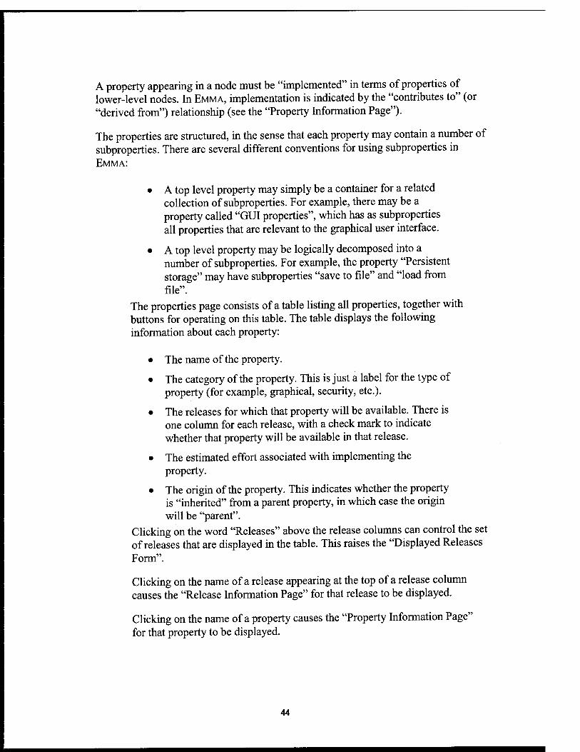
A property appearing in a node must be "implemented" in terms of properties of lower-level nodes. In EMMA, implementation is indicated by the "contributes to" (or "derived from") relationship (see the "Property Information Page").
The properties are structured, in the sense that each property may contain a number of subproperties. There are several different conventions for using subproperties in EMMA:
• A top level property may simply be a container for a related collection of subproperties. For example, there may be a property called "GUI properties", which has as subproperties all properties that are relevant to the graphical user interface.
• A top level property may be logically decomposed into a number of subproperties. For example, the property "Persistent storage" may have subproperties "save to file" and "load from file".
The properties page consists of a table listing all properties, together with buttons for operating on this table. The table displays the following information about each property:
• The name of the property.
• The category of the property. This is just a label for the type of property (for example, graphical, security, etc.).
• The releases for which that property will be available. There is one column for each release, with a check mark to indicate whether that property will be available in that release.
• The estimated effort associated with implementing the property.
• The origin of the property. This indicates whether the property is "inherited" from a parent property, in which case the origin will be "parent".
Clicking on the word "Releases" above the release columns can control the set of releases that are displayed in the table. This raises the "Displayed Releases Form".
Clicking on the name of a release appearing at the top of a release column causes the "Release Information Page" for that release to be displayed.
Clicking on the name of a property causes the "Property Information Page" for that property to be displayed.
44

At the bottom of the Properties page are a number of buttons for performing various operations: "Release/Phase Report" "New Property", "Derive Property", "Assign to Releases/Phases", "Assign for What If, "Paste Property", and "Help".
Displayed Releases Form To get to this page, click on the word "Releases" at the top of the release columns on the "Properties Page" or "Context Page". This form shows a table of all releases for the current node. Beside each release is a checkbox. If this is checked, then the release will be shown on the Properties Page, and if it is unchecked then the release will not be shown. This is convenient in cases where there is a large number of releases, and one would like to concentrate on some small subset of them (typically, the current release and the next couple of future releases).
Property Information Page This page displays information about a specific property or context element. To get to this page, click on the name of a property on the Properties Page or the name of a context element on the Context Page.
This page has the following information:
• The name of the property
• The estimated effort for implementing the property.
• The category of the property.
• The parent property (if the property is a subproperty).
• The description of the property.
• The justification for changes to the property. This field is relevant if the property is inherited from a higher-level node but has since been modified. In this case, the justification field explains the reason for the modification.
• What property (or context element) the current property (or context element) was derived from.
• What properties (or context elements) the current property (or context element) depends on.
• What properties (or context elements) the current property (or context element) contributes to.
45
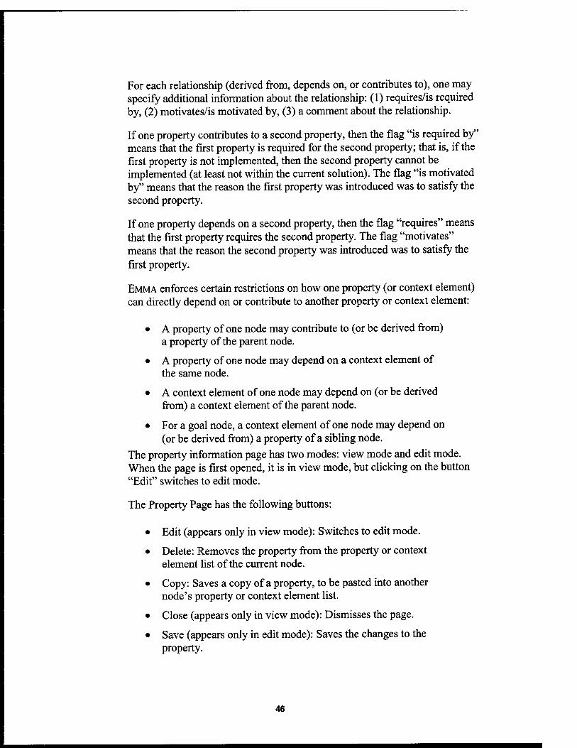
For each relationship (derived from, depends on, or contributes to), one may specify additional information about the relationship: (1) requires/is required by, (2) motivates/is motivated by, (3) a comment about the relationship.
If one property contributes to a second property, then the flag "is required by" means that the first property is required for the second property; that is, if the first property is not implemented, then the second property cannot be implemented (at least not within the current solution). The flag "is motivated by" means that the reason the fust property was introduced was to satisfy the second property.
If one property depends on a second property, then the flag "requires" means that the first property requires the second property. The flag "motivates" means that the reason the second property was introduced was to satisfy the first property.
EMMA enforces certain restrictions on how one property (or context element) can directly depend on or contribute to another property or context element:
• A property of one node may contribute to (or be derived from) a property of the parent node.
• A property of one node may depend on a context element of the same node.
• A context element of one node may depend on (or be derived from) a context element of the parent node.
• For a goal node, a context element of one node may depend on (or be derived from) a property of a sibling node.
The property information page has two modes: view mode and edit mode. When the page is first opened, it is in view mode, but clicking on the button "Edit" switches to edit mode.
The Property Page has the following buttons:
• Edit (appears only in view mode): Switches to edit mode.
• Delete: Removes the property from the property or context element list of the current node.
• Copy: Saves a copy of a property, to be pasted into another node's property or context element list.
• Close (appears only in view mode): Dismisses the page.
• Save (appears only in edit mode): Saves the changes to the property.
46
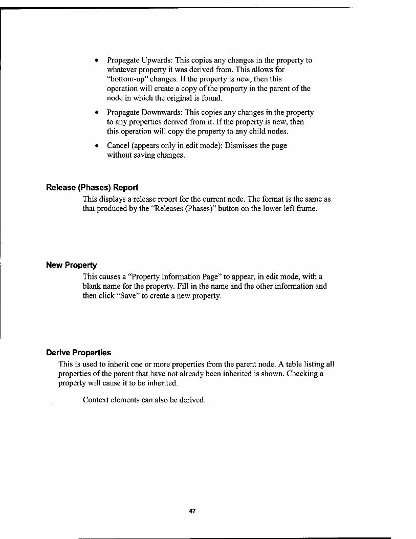
• Propagate Upwards: This copies any changes in the property to whatever property it was derived from. This allows for "bottom-up" changes. If the property is new, then this operation will create a copy of the property in the parent of the node in which the original is found.
• Propagate Downwards: This copies any changes in the property to any properties derived from it. If the property is new, then this operation will copy the property to any child nodes.
• Cancel (appears only in edit mode): Dismisses the page without saving changes.
Release (Phases) Report This displays a release report for the current node. The format is the same as that produced by the "Releases (Phases)" button on the lower left frame.
New Property This causes a "Property Information Page" to appear, in edit mode, with a blank name for the property. Fill in the name and the other information and then click "Save" to create a new property.
Derive Properties This is used to inherit one or more properties from the parent node. A table listing all properties of the parent that have not already been inherited is shown. Checking a property will cause it to be inherited.
Context elements can also be derived.
47

Assign to Releases This saves the changes to release assignments. To assign a property to a release, click on the cell in the row for that property and for the column for that release. This causes a check mark to appear. To unassign a property, just click on a check mark to remove it.
Assign for What If This button performs a provisional assignment of properties to releases for the purpose of analysis of the consequences of changing the release assignments.
Analysis This button is currently only available for the top goal. Clicking this button causes a completeness-consistency analysis of the current assignment of releases. If the assignment of releases is done provisionally, using "Assign for What If, this is called a "What If?" analysis, because it is possible to explore the consequences of a hypothetical change: moving a feature up to an earlier release, or pushing it back to a later release. This analysis is essentially the same as the analysis of a single release ("Release Analysis Page"), except that it includes information about all releases relevant to the current node.
Paste Property EMMA allows properties to be copied, and pasted as well as nodes. Clicking on the name of the property on the Properties page, and then clicking the Copy button copies a property. After a property has been copied, it can be pasted into the properties list or context element list of any node by going to the appropriate page and clicking the Paste Property button.
Help Brings up help for the Properties Page.
48

Context Page The context page has the same structure as the "Properties Page". While the Properties Page for a node describes what will be provided when the node is implemented (what functionality, what features, what nonfunctional properties), the Context Page details what the implementation of the node depends on. The sorts of things that can appear in the context page are:
• Definitions of terms used in requirements.
• Assumptions about the environment, or about user behavior, or about the behavior of other components.
•
•
Resources used in the implementation of the node which are produced elsewhere.
Assumed properties of other nodes.
A context element should generally have an origin. The origin of a context element can be external (that is the case for context elements of the top node), or it can be a higher-level node, or it can be a sibling node. If a context element has no origin, then EMMA considers that a potential sign of an inconsistency or incompleteness.
While a property for a node may only be derived from a property of the parent node, a context element can be derived from either the context of the parent node or from a property of a sibling node.
Status Page This page shows potential problems with a node, including incompleteness and discrepancies between the properties and context of a solution and the properties and context of its parent goal. The status page reports the following problems:
• Properties in a goal that are missing in the corresponding active solution. These represent unimplemented system features, and may either reflect incompleteness of the solution, or else a discrepancy that must be resolved through negotiation.
• Extra context elements present in a solution. Again, this discrepancy needs to be resolved through negotiation.
• Properties or context elements appearing in a solution that are different (in description, or name) than the corresponding item in the parent goal. This can
49

either represent a changed requirement that has not yet been taken into account in the implementation of the solution, or it can represent a discrepancy that needs to be resolved through negotiation.
Properties or context elements without release assignments.
Properties or context elements without dependencies. This is a likely indicator that a link has been forgotten.
Properties or context elements that make no contribution. This either indicates that link has been forgotten, or that the property or context element plays no role in the system being built (and so can be eliminated).
No properties associated with the node. This probably indicates an incompleteness of the EMMA solution structure for that node.
No context elements associated with the node. Again, this probably indicates incompleteness.
Descendents with warnings. This just lists all children nodes (and grandchildren, etc.) that have warnings associated, so that it is not necessary to search through the entire solution structure to find all the potential problems.
50

DISTRIBUTION LIST
addresses number of copies
DEBORAH A. CERINO 20 AFRL/IFTD 525 BROOKS ROAD ROME NY 13441-4505
DARYL MCCULLOU5H COGENTEX, INC. VILLAGE GREEN, SUITE 2 840 HANSHAW ROAD ITHACA/ NY 14850-1589
AFRL/IFOIL TECHNICAL LIBRARY 26 ELECTRONIC PKY ROME NY 13441-4514
ATTENTION: DTIC-OCC DEFENSE TECHNICAL INFO CENTER 8725 JOHN J. KINGMAN ROAD, STE 0944 FT. 8ELV0IR, VA 22060-6218
DEFENSE ADVANCED RESEARCH PROJECTS AGENCY 3701 NORTH FAIRFAX DRIVE ARLINGTON VA 22203-1714
ATTN: NAN PFRIMMER IIT RESEARCH INSTITUTE 201 MILL ST. ROME, NY 13440
AFIT ACADEMIC LIBRARY AFIT/LDR, 2950 P.STREET AREA 6, BLDG 642 WRIGHT-PATTERSON AFS OH 45433-7765
AFRL/HESC-TDC 2698 G STREET, 8LDG 190 WRIGHT-PATTERSON AF8 OH 45433-7604
DL-1

ATTN: SMDC IM PL US ARMY SPACE ft MISSILE DEF CMD P.O. BOX 1500 HUNTSVILLE AL 35807-3801
COMMANDER* CODE 4TL000D TECHNICAL LIBRARY, NAMC-WD 1 ADMINISTRATION CIRCLE CHINA LAKE CA 93555-6100
CDR, US ARMY AVIATION S MISSILE CMD REDSTONE SCIENTIFIC INFORMATION CTP ATTN: AMSAM-RD-08-R, (DOCUMENTS) REDSTONE ARSENAL AL 35898-5000
REPORT LIBRARY MS P364 LOS ALAMOS NATIONAL LABORATORY LOS ALAMOS NM 87545
ATTN: DEBORAH HART AVIATION BRANCH SVC 122.10 F0810A, RM 931 300 INDEPENDENCE AVE# SU WASHINGTON DC 20591
AFIWC/MSY 102 HALL BLVD, STE 315 SAN ANTONIO TX 78243-7016
ATTN: KAROLA M. YOURISON SOFTWARE ENGINEERING INSTITUTE 4500 FIFTH AVENUE PITTS3URGH PA 15213
USAF/AIR FORCE RESEARCH LABORATORY AFRL/VSOSA(LIBRARY-flLDG 1103) 5 WRIGHT DRIVE HANSCOM AF3 MA 01731-3004
ATTN: EILEEN LADUKE/D460 MITRE CORPORATION 202 BURLINGTON RD BEDFORD MA 01730
DL-2

OUSD(P)/0TSA/OUTO 1 ATTN: PATRICK 6- SULLIVAN, JR. 400 ARMY NAVY DRIVE SUITE 300 ARLINGTON VA 22202
AFRL/IFT 1 525 BROOKS ROAD ROME, NY 13441-4505
AFRL/IFT« 1 525 BROOKS ROAD ROME, NY 13441-4505
CENTRIC ENGINEERING SYSTEM, INC. 1 624 EAST EVELYN AVENUE SUNNYVALE, CA 94086-6488
FLUENT INCORPORATED 1 500 DAVIS STREET, SUITE 600 EVANSTON, IL 60201
THE MACNEAL-SCHWENDLER CORPORATION 1 815 COLORADO BOULEVARD LOS ANGELES, CA 90041-1777
MOLECULAR SIMULATIONS, INC. 1 9865 SCRANTON ROAD SAN DIEGO, CA 92121-3752
CENTRIC ENGINEERING SYSTEM, INC. 1 624 EAST EVELYN AVENUE SUNNYVALE, CA 94086-6488
«U.S. GOVERNMENT PR,NT,NG OFFICE: 2000-510-079-81227
DL-3

MISSION OF
ÄFRL/INFORMÄTIONDIRECTORATE (IF)
The advancement and application of information systems science and
technology for aerospace command and control and its transition to air,
space, and ground systems to meet customer needs in the areas of Global
Awareness, Dynamic Planning and Execution, and Global Information
Exchange is the focus of this AFRL organization. The directorate's areas
of investigation include a broad spectrum of information and fusion,
communication, collaborative environment and modeling and simulation,
defensive information warfare, and intelligent information systems
technologies.