TAPPING PRODUCTS & ADVANCED SOLUTIONS - … Catalog.pdfINNOVATION I PERFORMANCE I QUALITY TAPPING...
76
INNOVATION I PERFORMANCE I QUALITY TAPPING PRODUCTS & ADVANCED SOLUTIONS www.bilzusa.com we hold our promise
Transcript of TAPPING PRODUCTS & ADVANCED SOLUTIONS - … Catalog.pdfINNOVATION I PERFORMANCE I QUALITY TAPPING...

I N N O V A T I O N I P E R F O R M A N C E I Q U A L I T Y
TAPPING PRODUCTS & ADVANCED SOLUTIONS
www.bilzusa.com
we hold our promise

2 www.bilzusa.com
we hold our promise
The Foundation. For over 90 years, Bilz has been a leading supplier of tool holders, tapping technology and
shrink fit systems. The main reason for this success is our people. Bilz has over 350 experienced and
motivated individuals working every day to improve and enhance the products we offer. Our goal is to
improve your manufacturing processes with a complete set of solutions that are efficient and dependable.
As a result, we have become an innovative and trusted partner to companies around the world in industries
including aerospace, automotive, die mold & machining, medical equipment and power generation.

3www.bilzusa.com
Dear Reader,
As everyone knows, money is made at the “cutting edge”. The productivity of this cutting edge influences
the total costs of cutting processes, while its share of total manufacturing costs amounts to only 4–6%.
Most production and cutting experts will agree with these statements.
What is required to fully profit from the performance of the cutting edge
and increase tool life? This catalog will support you in selecting the
optimal clamping tools for your “cutting edges”.
Our long experience as a traditional family-run company helps
us to develop products you can rely on . BIlz has compiled
a comprehensive product range in this catalog. Many
improvements have been included.
“Always better” is not just a slogan for us. It is a promise,
our commitment to quality. We and our products keep
our promises. In addition to this product range we can
offer you various custom-designed solutions.
Please talk to us about new solutions for your applications.
Many people react, we act.
On behalf of the whole Bilz Team,

4 www.bilzusa.comwww.bilzusa.com4
For decades, Bilz has been the global leader in tapping technol-ogy. Quality engineered and well designed, Bilz tap holders are the industry standard.
Special features like length compensation (tension/compres-sion), quick change, parallel �oat, internal coolant or external coolant are incorporated in many different combinations in our chucks.
ADVANTAGES• Faster Tool Set-ups• Increased Tap Life• Improved Thread Quality• Faster Tool Changes
APPLICATIONS• Tapping and thread forming on all possible applications with many different machine spindle connections.
TAPPING
Minimum Quantity Lubricant (MQL) technology provides unmatched ef�ciency in coolant delivery. The system delivers coolant immediately upon start-up with consistent pressure, and the optimized sealed design provides a leak-free coolant stream.
Reduced coolant usage and coolant handling leads to a safer workplace, lower maintenance costs, and a smaller impact on the environment. MQL is available inShrink Fit holders and Synchro Chuck holders.
ADVANTAGES• More ef�cient coolant consumption• Environmentally friendly• Up to 100% increase in tool life• Reduce coolant costs up to 19%
APPLICATIONS• Perfect for any application where safer and more-ef�cient coolant usage is desired. Speci�c industries include Aerospace, Automotive, Die & Mold, Medical Equipment and more.
The finest shrink fit holders available. Precise manufacturing and our exclusive “counter bore” technology optimize the advan-tages of using shrink �t tooling. Combine the Bilz ThermoGrip holders with the Bilz ThermoGrip machines and you have the ultimate shrink �t system.
Bilz holders offer the best part�nish quality, longer tool life, and higher feed rates and speeds. All of this is accomplished due to micrometer accuracy in runout, high cutting tool rigidity and extremely high clamping forces.
TOOL OPTIONS• Standard chucks• Slimline chucks• Heavy duty (thick walled) chucks• JetSleeve• TER shrink-fit collets
APPLICATIONS• Milling, drilling and reaming• Milling and reaming on driven tooling• Micro milling applications
INDUCTIONSHRINK-FIT SYSTEM
(MQL) MINIMUMQUANTITY LUBRICANT
Our CNC Holder line providesoptions for all industry-standardsizes and con�gurations for colletchucks, end mill holders, shell millholders, hi-power milling chucks, and face mill holders.
Each product represents thelatest technology, and re�ectsour commitment to quality and innovation. We also support our products with unmatched appli-cation expertise and customer service.
ADVANTAGES• Latest tool holding technology• Extensive product line• Strong, high-quality products• Very accurate and durable
APPLICATIONS• CNC holders are used in a variety of industries including Aerospace, Automotive, Die & Mold, Medical Equipment and more.
CNC HOLDERS FLOATING HOLDERS
Bilz Floating Holders enable the serial production of perfectly aligned reamed bores with the automatic centering of the reamer after every cycle, protecting the reamer from any side forces.
Our Floating Holders can be usedhorizontally or vertically and canbe delivered with internal coolantsupply and integrated lengthadjustment.
ADVANTAGES• Axial float without play• Maintenance free• Adjustable centering• High coolant pressure
APPLICATIONS• Using reamer tools where the machining spindle and the bore in the workpiece are not 100% aligned.• Used in transfer lines, lathes and custom machinery
Our Specialty Holders representa unique set of products that offercost-effective capabilities you won’t �nd from any other manu-facturer. In fact, nearly all SpecialHolders can demonstrate a substantial cost savings when compared to other methods.
ADVANTAGES• Expand your capabilities• Make your spindle more productive• Meet unique customer requirements• Open a new range of potential
APPLICATIONS• Specialty tool holders can be used to help machine unique profiles, provide critical part ID and marking, and even set and drive studs.
SPECIALTOOL HOLDERS
BILZ—FIT FOR THE FUTURE BILZ—FIT FOR THE FUTUREBILZ—FIT FOR THE FUTURE

5www.bilzusa.comwww.bilzusa.com 5
For decades, Bilz has been the global leader in tapping technol-ogy. Quality engineered and well designed, Bilz tap holders are the industry standard.
Special features like length compensation (tension/compres-sion), quick change, parallel �oat, internal coolant or external coolant are incorporated in many different combinations in our chucks.
ADVANTAGES• Faster Tool Set-ups• Increased Tap Life• Improved Thread Quality• Faster Tool Changes
APPLICATIONS• Tapping and thread forming on all possible applications with many different machine spindle connections.
TAPPING
Minimum Quantity Lubricant (MQL) technology provides unmatched ef�ciency in coolant delivery. The system delivers coolant immediately upon start-up with consistent pressure, and the optimized sealed design provides a leak-free coolant stream.
Reduced coolant usage and coolant handling leads to a safer workplace, lower maintenance costs, and a smaller impact on the environment. MQL is available inShrink Fit holders and Synchro Chuck holders.
ADVANTAGES• More ef�cient coolant consumption• Environmentally friendly• Up to 100% increase in tool life• Reduce coolant costs up to 19%
APPLICATIONS• Perfect for any application where safer and more-ef�cient coolant usage is desired. Speci�c industries include Aerospace, Automotive, Die & Mold, Medical Equipment and more.
The finest shrink fit holders available. Precise manufacturing and our exclusive “counter bore” technology optimize the advan-tages of using shrink �t tooling. Combine the Bilz ThermoGrip holders with the Bilz ThermoGrip machines and you have the ultimate shrink �t system.
Bilz holders offer the best part�nish quality, longer tool life, and higher feed rates and speeds. All of this is accomplished due to micrometer accuracy in runout, high cutting tool rigidity and extremely high clamping forces.
TOOL OPTIONS• Standard chucks• Slimline chucks• Heavy duty (thick walled) chucks• JetSleeve• TER shrink-fit collets
APPLICATIONS• Milling, drilling and reaming• Milling and reaming on driven tooling• Micro milling applications
INDUCTIONSHRINK-FIT SYSTEM
(MQL) MINIMUMQUANTITY LUBRICANT
Our CNC Holder line providesoptions for all industry-standardsizes and con�gurations for colletchucks, end mill holders, shell millholders, hi-power milling chucks, and face mill holders.
Each product represents thelatest technology, and re�ectsour commitment to quality and innovation. We also support our products with unmatched appli-cation expertise and customer service.
ADVANTAGES• Latest tool holding technology• Extensive product line• Strong, high-quality products• Very accurate and durable
APPLICATIONS• CNC holders are used in a variety of industries including Aerospace, Automotive, Die & Mold, Medical Equipment and more.
CNC HOLDERS FLOATING HOLDERS
Bilz Floating Holders enable the serial production of perfectly aligned reamed bores with the automatic centering of the reamer after every cycle, protecting the reamer from any side forces.
Our Floating Holders can be usedhorizontally or vertically and canbe delivered with internal coolantsupply and integrated lengthadjustment.
ADVANTAGES• Axial float without play• Maintenance free• Adjustable centering• High coolant pressure
APPLICATIONS• Using reamer tools where the machining spindle and the bore in the workpiece are not 100% aligned.• Used in transfer lines, lathes and custom machinery
Our Specialty Holders representa unique set of products that offercost-effective capabilities you won’t �nd from any other manu-facturer. In fact, nearly all SpecialHolders can demonstrate a substantial cost savings when compared to other methods.
ADVANTAGES• Expand your capabilities• Make your spindle more productive• Meet unique customer requirements• Open a new range of potential
APPLICATIONS• Specialty tool holders can be used to help machine unique profiles, provide critical part ID and marking, and even set and drive studs.
SPECIALTOOL HOLDERS
BILZ—FIT FOR THE FUTURE BILZ—FIT FOR THE FUTUREBILZ—FIT FOR THE FUTURE

6 www.bilzusa.com
Bilz is the global leader in precision quick-change tapping systems for CNC machine tools, offering a broad range of choices with full tension/compression compensation as well as self-reversing tapping attachments. Bilz CNC tapping solutions covers a full-range of applications from rigid tapping, where the Synchro Chuck offers improved tool life and thread quality, through high-speed tapping at speeds up to 4,000 RPM using a tool-changer compatible gear attachment (GNCK) with integral reversing capability. Bilz tapping systems are available in all commonly used machine tool spindle styles including HSK, V-Flange style (BT or CAT), DIN (SK or AD) and various straight shank configurations.
Rigid Tapping Holders – Synchro Chuck
•ForrigidtappingonCNCmachinetools•Compensatesforsynchronizationerrorsto extend tap life and to improve thread quality•Forhigh-speedsteelandcarbidetaps•Precisioncolletwithcoolantthrough tool options
Rigid Tapping Holders – WF
•Basicquick-changetapholders for use on CNC machine tools with rigid feed capability•Variousshankoptionsavailable,integral
(ACME, B-taper, Morse taper, HSK, straight, and TR) and modular (CAT, MAS-BT)
•Thru-coolantupto50bar/725psi
Compensating Tapping Holders – WFLC & WFLK
•Lengthcompensatingquick-changeholdersavailablewithtension-onlyortension/compression feature that compensates for differences between spindle speed, feed rate, and tap pitch.•Uniqueballplacementforsuperiorlengthcompensation•Availableintegral“hard-start”mechanismadjustscuttingpressuretoensurepositivestart of tapping cycle•Variousshankoptionsavailable,integral(ACME,B-taper,Morsetaper,HSK,straight,andTR)
and modular (CAT, MAS-BT)•Thru-coolantto50bar/750psiavailable(WFLC-IKP)
Self-Reversing Tapping Attachments GNCN and GNCK
•Tappingattachmentwithintegralreversinggear•Tappingspeedsupto4,000RPM•ForCNCmachineswithautomatictoolchangers•Thru-coolantto50bar/750psi(GNCK)
QUICK-CHANGE TAPPING SYSTEMS FOR CNC MACHINES

7www.bilzusa.com
Positve Drive Length-Adjustable – WEN
•Length-adjustable,non-torquedesignallowstaplengthtobepreset•Excellentforclose-centerapplications•Suitableforusewiththru-coolantorcoolant-aroundtaps(KP-option)•Availableinextendedlengths,andwithoptionalthru-coolant
Torque-Control – WES
•Integraltorqueclutchpreventstapbreakage•Left-handtapclutchesavailable•Suitableforusewiththru-coolantorcoolant-aroundtaps(KP-option)
Torque-Control Length-Adjustable – WESN
•Length-adjustabledesignallowstaplengthtobepreset•Integral,adjustabletorqueclutchpreventstapbreakage•Suitableforusewiththru-coolantorcoolant-aroundtaps(KP-option)•Availableinextendedlengths,andwithoptionalthru-coolant
Thru-Coolant Collet Type – WE IKP-ESX
•Idealforcarbidetapsandthru-coolanttappingapplications•Availableinsingle-angle(ER)-16,-20,-25,-32and-40colletsizes
Reducing Adapter – WRE
•Allowstheuseofsmallerseriesadaptersinlargertappingchucks•Reducedcostforsmallersizetapping
Bilz modular, quick-change tap adapters provide the ultimate in machining flexibility. They are available in a full-range of sizes, styles, and configurations to handle virtually any application requirement on manual, CNC, or special machine tools at any volume level. Bilz offers solid, length-adjustable, close-center, and thru-coolant capable tap adapters in all standard configurations meeting ANSI, DIN, ISO, and JIS specifications. Bilz tap adapters are precision manufactured to ensure long tap life as well as optimum performance and low life-cycle cost.
Positive Drive – WE
•Basicnon-torquequick-changetapadapter•Suitableforusewiththru-coolantorcoolant-aroundtaps(KP-style)•Interchangeablewithotherbrandsoftapadapters
QUICK-CHANGE TAP ADAPTERS

8 www.bilzusa.com
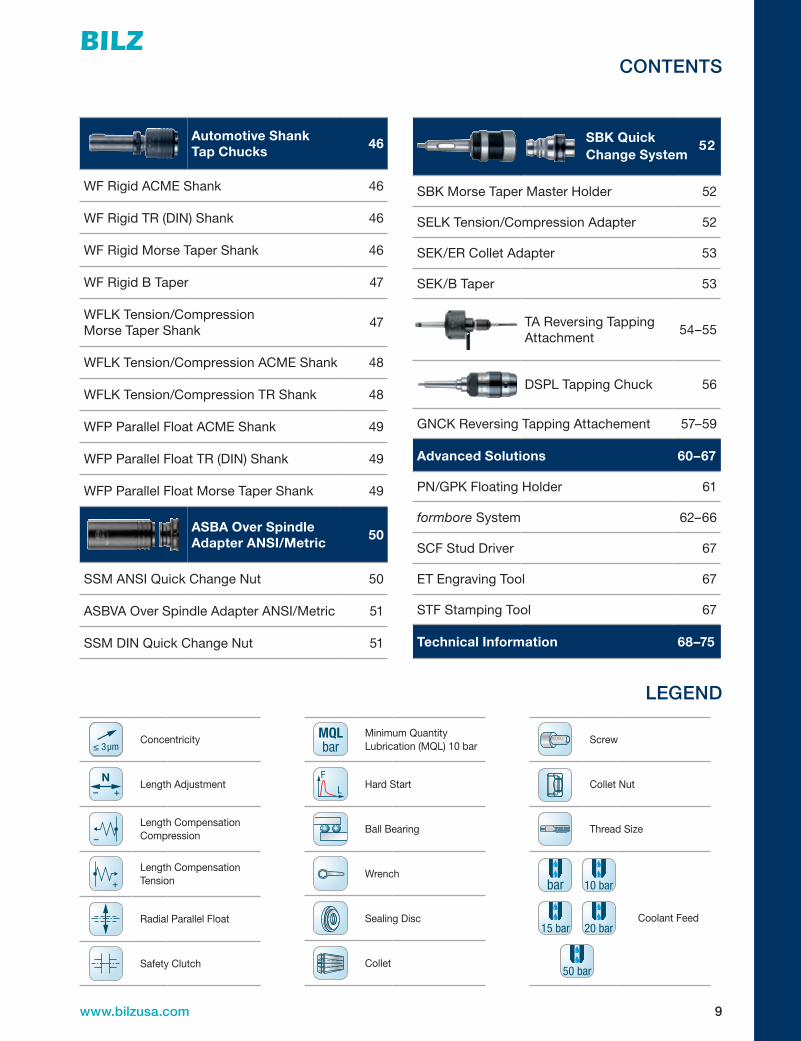
CONTENTS
Legend 9
Synchro Chuck Introduction
10–11
Synchro Chuck HSK Shank 12–13
Synchro Chuck Straight Shank 14
Synchro Chuck V-Flange 14
ER-GB Square Drive Tap Collets 15–16
DS/ER Seal Discs 17
ER Collet Nuts 18
ER Wrenches 19
Synchro Chuck Accessories 20–21
MQL Overview 22–23
Quick Change Tapping Systems Introduction
24–25
WF Rigid CAT V-Flange Coolant Through 26
WF Rigid BT Flange Coolant Through 26
WF Rigid Straight Shank Coolant Through 27
WFLKTension/CompressionCATV-Flange 28
WFLKTensionOnlyCATV-Flange 28
WFLKTension/CompressionBTFlange 29
WFLKTensionOnlyBTFlange 29
WFLKTension/Compression Straight Shank
30
WFLKTensionOnlyStraightShank 30
WFLCTension/Compression Straight Shank Coolant Through
30
WFP Parallel Float CAT V-Flange 31
WFP Parallel Float BT Flange 31
WFP Parallel Float Straight Shank 31
WFLCTension/CompressionHSKShank 32
WFLCTensionOnlyHSKShank 32
WFLCTension/CompressionHSKShankCoolant Through
33
WFLCTensionOnlyHSKShank Coolant Through
33
WE/WER ANSI Adapter
34
WE/WER-KP ANSI Slotted Adapter 35
WE/WE-KP DIN Adapter 36
Tap Shank and Square Dimensional Chart 37
WES/WESR ANSI Torque Control Adapter
38
WES DIN Torque Control Adapter 39
WEN/WEN-KP ANSI AdjustableLengthAdapter
40
WE/WEN-KPDINAdjustableLengthAdapter
41
WEN/WEN-KP/ WEN-IKP Extended LengthAdapter
42
WE-ER Collet Adapter 43
WEK Extended Range Adapter 43
WESK Extended Range Torque Control Adapter
43
WRE Reducing Adapter 43
ER Single Angle Collets 44–45
9www.bilzusa.com
CONTENTS
LEGEND
≤ 3μmConcentricity
– +
NLengthAdjustment
–
LengthCompensationCompression
+
LengthCompensationTension
Radial Parallel Float
Safety Clutch
MQLbar
Minimum Quantity Lubrication(MQL)10bar
F
L Hard Start
Ball Bearing
Wrench
Sealing Disc
Collet
Screw
Collet Nut
Thread Size
bar 10 bar
15 bar 20 bar
50 bar
Coolant Feed
Automotive Shank Tap Chucks
46
WF Rigid ACME Shank 46
WF Rigid TR (DIN) Shank 46
WF Rigid Morse Taper Shank 46
WF Rigid B Taper 47
WFLKTension/Compression Morse Taper Shank
47
WFLKTension/CompressionACMEShank 48
WFLKTension/CompressionTRShank 48
WFP Parallel Float ACME Shank 49
WFP Parallel Float TR (DIN) Shank 49
WFP Parallel Float Morse Taper Shank 49
ASBA Over Spindle Adapter ANSI/Metric
50
SSM ANSI Quick Change Nut 50
ASBVA Over Spindle Adapter ANSI/Metric 51
SSM DIN Quick Change Nut 51
SBK Quick
52
Change System
SBK Morse Taper Master Holder 52
SELKTension/CompressionAdapter 52
SEK/ER Collet Adapter 53
SEK/B Taper 53
TA Reversing Tapping Attachment
54–55
DSPLTappingChuck 56
GNCK Reversing Tapping Attachement 57–59
Advanced Solutions 60–67
PN/GPK Floating Holder 61
formbore System 62–66
SCF Stud Driver 67
ET Engraving Tool 67
STF Stamping Tool 67
Technical Information 68–75

10 www.bilzusa.com
SY
NC
HR
O C
HU
CK
SQ
UIC
K C
HA
NG
E TA
PP
ING
SP
EC
IALT
Y P
RO
DU
CT
ST
EC
HN
ICA
L
SYNCHRO CHUCKS
V I E WT H EW E B S I T E
INCREASE TAP TOOL LIFE AND IMPROVE THREAD FORM QUALITY
The Bilz Synchro Chuck was originally developed for tapping applications in automotive engine manufacturing.
Today, all manufacturing with tapping operations can bene�t by using the Synchro Chuck. The features and
design of this product—“Elastomer Damping” and “Precision Pin” construction, allow for excellent tap thread
form in synchronized tapping applications. If you are tapping holes
on CNC equipment, you will want to add the Bilz Synchro Chuck
to your tool clamping system.
Maximize your tap life and maximize your thread
quality with the Synchro chuck.
10 www.bilzusa.com

11www.bilzusa.com
TE
CH
NIC
AL
SP
EC
IALT
Y P
RO
DU
CT
SQ
UIC
K C
HA
NG
E T
AP
PIN
GS
YN
CH
RO
CH
UC
KS
SCK | Synchro Chuck
Market demands have triggered the development ofthenewdesignBILZsynchrochucks.Lengthpre-setting of the tap position can be completed from both sides of the chuck, the minimum quantity lubrication has been optimized and comes with an absolute leak free sealing system.
The tension and compression length compensation, (+/–0.15mm)incombinationwithradialdampeningeffect compensates small synchronisation errors and torque peaks. Through this defined application com-pensation the user achieves reduced tap flank wear in combination with considerably less cutting loads which in turn increases tap life thread quality.
The “Elastomer” dampening elements are form-secure, they are also resistant to all coolant substances used in today’s machining centers.
Features:• Minimumcompensationontension/compression• SCK1+2,+/–0.15mm;SCK3,+/–0.8mm;
SCK4,+/–1.5mm
Advantages:•Reductionofthepressureonthethreadflanks•Compensationofthesynchronisationerror•Dampingoflengthadjustmentscrew—nodamage
of screw or tap
Benefits:•Higherlifetimeofthetaps•Lessnumberoftoolsrequired•Reducedriskoftapbreakage•Betterthreadquality
Application: Tapping and roll forming on machines with synchronised feed (speed/feed synchronisation)
Machine Type: Machining centers, CNC turning and special purpose machines with synchronised feed for the tapping operation

12 www.bilzusa.com
SY
NC
HR
O C
HU
CK
SQ
UIC
K C
HA
NG
E TA
PP
ING
SP
EC
IALT
Y P
RO
DU
CT
ST
EC
HN
ICA
L
SCK | Synchro Chucks
SCK/HSK-ESX
SAP No. Designation
Tap Size Comp
Dimensions (mm)Collet Seald1 d2 d3 d L l1 l2
Coolant Through, 1-Channel MQL5010567 SCK1-95.5/HSK-A63-ESX20-BL M4-M12 +/-0.15 4-12 34 34 63 95.5 69.5 37.5 ER20-GB DS/ER20
5013409 SCK1-160/HSK-A63-ESX20-BL M4-M12 +/-0.15 4-12 34 34 63 160 134 37.5 ER20-GB DS/ER20
5012119 SCK1-102/HSK-A100-ESX20-BL M4-M12 +/-0.15 4-12 34 34 100 102 73 37.5 ER20-GB DS/ER20
5011981 SCK2-109/HSK-A63-ESX32-BL M4-M20 +/-0.15 4-20 50 50 63 109 83 43.5 ER32-GB DS/ER32
5012062 SCK2-115.5/HSK-A100-ESX32-BL M4-M20 +/-0.15 4-20 50 50 100 115.5 86.5 43.5 ER32-GB DS/ER32
5017524 SCK3-146.5/HSK-A63-ESX40-BL M10-M30 +/-0.8 10-22 63 58.5 63 146.5 120.5 50.3 ER40-GB DS/ER40
5017526 SCK3-138/HSK-A100-ESX40-BL M10-M30 +/-0.8 10-22 100 58.5 100 138 109 50.3 ER40-GB DS/ER40
Seepage15and16forGBTapColletsSeepage17forSealDisc
SCK/HSK-ESX
SAP No. Designation
Tap Size Comp
Dimensions (mm)Collet Seald1 d2 d3 d L l1 l2
2-Channel MQL5011971 SCK1-B-95.5/HSK-A63-ESX20-GN M4-M12 +/-0.15 4-12 34 34 63 95.5 69.5 37.5 ER20-GB DS/ER20
5024976 SCK1-B-160/HSK-A63-ESX20-GN M4-M12 +/-0.15 4-12 34 34 63 160 134 37.5 ER20-GB DS/ER20
5012122 SCK1-B-102/HSK-A100-ESX20-GN M4-M12 +/-0.15 4-12 34 34 100 102 73 37.5 ER20-GB DS/ER20
5011987 SCK2-B-109/HSK-A63-ESX32-GN M4-M20 +/-0.15 4-20 50 50 63 109 83 43.5 ER32-GB DS/ER32
5012067 SCK2-B-115.5/HSK-A100-ESX32-GN M4-M20 +/-0.15 4-20 50 50 100 115.5 86.5 43.5 ER32-GB DS/ER32
5052547 SCK3-B-146.5/HSK-A63-ESX40-GN M10-M30 +/-0.8 10-22 63 58.5 63 146.5 120.5 50.3 ER40-GB DS/ER40
5016680 SCK3-B-138/HSK-A100-ESX40-GN M10-M30 +/-0.8 10-22 100 58.5 100 138 109 50.3 ER40-GB DS/ER40
Seepage15and16forGBTapColletsSeepage17forSealDisc
l
dd 1
1
d2
l2
d3
l
dd 1
1
d2
l2
d3
DIN69893A – + 50 bar – +
N
DIN69893A – +
MQL10 bar – +
N

13www.bilzusa.com
TE
CH
NIC
AL
SP
EC
IALT
Y P
RO
DU
CT
SQ
UIC
K C
HA
NG
E T
AP
PIN
GS
YN
CH
RO
CH
UC
KS
SCK | Synchro Chucks
DIN69893A – + 50 bar – +
N
SCK/HSK-BZ
SAP No. Designation
Tap Size Comp
Dimensions (mm)Collet Seald1 d2 d3 d l l1 l2
2-Channel MQL5022432 SCK1-B-86/HSK-A63-BZ18-GN M3.5-M14 +/-0.15 4.0-10.0 25 34 63 86 60 28 BZ18 DS/ER20
5024981 SCK1-B-92.5/HSK-A100-BZ18-GN M3.5-M14 +/-0.15 4.0-10.0 25 34 100 92.5 63.5 28 BZ18 DS/ER20
5024893 SCK2-B-104/HSK-A63-BZ25-GN M10-M20 +/-0.15 10.0-18.0 34 50 63 104 78 38.5 BZ25 DS/ER25
5024894 SCK2-B-110.5/HSK-A100-BZ25-GN M10-M20 +/-0.15 10.0-18.0 34 50 100 110.5 81.5 38.5 BZ25 DS/ER25
Seepage15and16forGBTapColletsSeepage17forSealDisc
d
l1
l
l2
d2d1
sealed nut BM…-IK
d3
DIN69893A – +
MQL10 bar – +
N
d
l1
l
l2
d2d1
sealed nut BM…-IK
d3

14 www.bilzusa.com
SY
NC
HR
O C
HU
CK
SQ
UIC
K C
HA
NG
E TA
PP
ING
SP
EC
IALT
Y P
RO
DU
CT
ST
EC
HN
ICA
L
SCK | Synchro Chucks
SCK Straight Shank – Coolant Through
SAP No. Designation
Tap Size Comp
Dimensions (mm)Collet Seald1 d2 d3 d l l1
Metric Shank5023361 SCK1-73/W20-ESX20-BL M4-M12 +/-0.15 4-12 34 34 20 73 57 ER20-GB DS/ER20
5012220 SCK1-73/W25-ESX20-BL M4-M12 +/-0.15 4-12 34 34 25 73 57 ER20-GB DS/ER20
5012283 SCK1-73/MS25-ESX20-BL* M4-M12 +/-0.15 4-12 34 34 25 73 57 ER20-GB DS/ER20
5012276 SCK2-87.5/W25-ESX32-BL M4-M20 +/-0.15 4-20 50 50 25 87.5 57 ER32-GB DS/ER32
5012284 SCK2-87.5/MS25-ESX32-BL* M4-M20 +/-0.15 4-20 50 50 25 87.5 57 ER32-GB DS/ER32
5017528 SCK3-113.5/W32-ESX40-BL M10-M30 +/-0.8 10-22.0 63 58.5 32 113.5 61 ER40-GB DS/ER40
Inch Shank5020050 SCK1-73/M25.4-ESX20-BL M4-M12 +/-0.15 4.5-11.2 34 34 25.4 73 57 ER20-GB DS/ER20
5013247 SCK2-87.5/M25.4-ESX32-BL M4-M20 +/-0.15 4.5-18 50 50 25.4 87.5 57 ER32-GB DS/ER32
Seepage15and16forGBTapColletsSeepage17forSealDisc
Holders for Straight Shank Synchro Chucks
SAP No. Catalog No. Description
Dimensions (mm)d1 d2 l1 l
12934216 12934216 CAT40w/1Bore 1.0 45 68.5 1.375
12934218 12934218 CAT50w/1Bore 1.0 70 84.5 1.375
12934219 12934219 CAT50w/1.5Bore 1.5 70 84.5 1.375
12934221 12934221 BT40w/1Bore 1.0 45 68.5 1.062
12934223 12934223 BT50w/1Bore 1.0 70 84.5 1.875
12934880 12934880 BT50w/1.5Bore 1.5 70 84.5 1.875
99831412 WA25/A126/B40* DIN-40Taper25mmBore 25mm 50 54.0 1.378
98831533 WA25/A126/B50* DIN-50Taper25mmBore 25mm 70 54.0 1.378
*Forcoolantthrutheflange,usewithMS25shanktools.
l1 l
d d1 d2
l2
d3
DIN1835B+E – + 50 bar – +
N
ød2
ød1
l
l1

15www.bilzusa.com
TE
CH
NIC
AL
SP
EC
IALT
Y P
RO
DU
CT
SQ
UIC
K C
HA
NG
E T
AP
PIN
GS
YN
CH
RO
CH
UC
KS
ER-GB | Collets
ER-GB – Inch
Shankd
(inch)
Square SW
(inch)l2
(mm)Pipe Tap
Catalog No.
ER 11-GB ER 16-GB ER 20-GB ER 25-GB ER 32-GB ER 40-GB0.141 0.110 18 1411.03585 1416.03585
0.168 0.131 18 1416.04275 1420.04275 1425.04275 1432.04275
0.194 0.152 18 1416.04935 1420.04935 1425.04935 1432.04935
0.22 0.165 18 1416.05595 1420.05595 1425.05595 1432.05595
0.255 0.191 18 1416.06485 1420.06485 1425.06485 1432.06485 1440.06485
0.318 0.238 22 1416.08085 1420.08085 1425.08085 1432.08085 1440.08085
0.323 0.242 22 1420.08215 1425.08215 1432.08215 1440.08215
0.367 0.275 22 1420.09325 1425.09325 1432.09325 1440.09325
0.381 0.286 22 1420.09685 1425.09685 1432.09685 1440.09685
0.429 0.322 25 1425.10905 1432.10905 1440.10905
0.437 0.328 25 3 1425.11104 1432.11104 1440.11104
0.48 0.360 25 1425.12195 1432.12195 1440.12195
0.542 0.406 25 1432.13775 1440.13775
0.562 0.421 25 3 1432.14274 1440.14274
0.59 0.442 25 1432.14995 1440.14995
0.652 0.489 25 1432.16565 1440.16565
0.687 0.515 25 3 1440.17454
0.697 0.523 25 1440.17705
0.70 0.531 25 3 1440.17784
0.76 0.570 25 1440.19305
0.80 0.600 28 1440.20325
l2
d
SW
/ SQ

16 www.bilzusa.com
SY
NC
HR
O C
HU
CK
SQ
UIC
K C
HA
NG
E TA
PP
ING
SP
EC
IALT
Y P
RO
DU
CT
ST
EC
HN
ICA
L
ER-GB – Metric
Shankd
(inch)
Square SW
(inch)l2
(mm) STD
Catalog No.
ER 11-GB ER 16-GB ER 20-GB ER 25-GB ER 32-GB ER 40-GB2.8 2.1 12 DIN 1411.02800
3.5 2.7 14 DIN 1411.03500
4 3 14 DIN 1411.04000
4 3.15/3.2 18 ISO, JIS 1416.04002 1420.04002 1425.04002 1432.04002
4.5 3.4 18 DIN 1411.04500 1416.04500 1420.04500 1425.04500 1432.04500
5 4 18 ISO, JIS 1416.05002 1420.05002 1425.05002 1432.05002
5.5 4.3 18 DIN 1416.05500 1420.05500 1425.05500 1432.05500
5.5 4.5 18 JIS 1416.05501 1420.05501 1425.05501 1432.05501
6 4.5 18 JIS 1416.06001 1420.06001 1425.06001 1432.06001 1440.06001
6 4.9 18 DIN 1411.06000 1416.06000 1420.06000 1425.06000 1432.06000 1440.06000
6.2 5 18 JIS 1416.06201 1420.06201 1425.06201 1432.06201 1440.06201
6.3 5 18 ISO 1416.06302 1420.06302 1425.06302 1432.06302 1440.06302
7 5.5 18 DIN, JIS 1416.07000 1420.07000 1425.07000 1432.07000 1440.07000
7.1 5.6 18 ISO 1416.07102 1420.07102 1425.07102 1432.07102 1440.07102
8 6.2/6.3 22 DIN, ISO 1416.08000 1420.08000 1425.08000 1432.08000 1440.08000
8.5 6.5 22 JIS 1416.08501 1420.08501 1425.08501 1432.08501 1440.08501
9 7.0/7.1 22 DIN, ISO 1416.09000 1420.09000 1425.09000 1432.09000 1440.09000
10 8 25 DIN, ISO 1420.10000 1425.10000 1432.10000 1440.10000
10.5 8 25 JIS 1420.10501 1425.10501 1432.10501 1440.10501
11 9 25 DIN 1420.11000 1425.11000 1432.11000 1440.11000
11.2 9 25 ISO 1420.11202 1425.11202 1432.11202 1440.11202
12 9 25 DIN 1425.12000 1432.12000 1440.12000
12.5 10 25 ISO, JIS 1425.12502 1432.12502 1440.12502
14 11.0/11.2 25DIN, ISO,
JIS1425.14000 1432.14000 1440.14000
15 12 25 JIS 1425.15001 1432.15001 1440.15001
16 12 25 DIN 1425.16000 1432.16000 1440.16000
17 13 25 JIS 1432.17001 1440.17001
18 14.0/14.5 25 DIN, ISO 1432.18000 1440.18000
20 16 28 DIN, ISO 1432.20000 1440.20000
22 18 28 DIN 1440.22000
ER-GB | Collets
l2
d
SW
/ SQ

17www.bilzusa.com
TE
CH
NIC
AL
SP
EC
IALT
Y P
RO
DU
CT
SQ
UIC
K C
HA
NG
E T
AP
PIN
GS
YN
CH
RO
CH
UC
KS
Sealing Discs
Sealing Capacity (mm) (inch) (inch)
Catalog No.DS/ER 16 DS/ER 20 DS/ER 25 DS/ER 32
3.00...2.50 0.1181...0.0984 3916.00300 3920.00300 3925.00300 3932.00300
3.50...3.00 0.1378...0.1181 1/8 3916.00350 3920.00350 3925.00350 3932.00350
4.00...3.50 0.1575...0.1378 5/32 3916.00400 3920.00400 3925.00400 3932.00400
4.50...4.00 0.1772...0.1575 3916.00450 3920.00450 3925.00450 3932.00450
5.00...4.50 0.1969...0.1772 3/16 3916.00500 3920.00500 3925.00500 3932.00500
5.50...5.00 0.2165...0.1969 3916.00550 3920.00550 3925.00550 3932.00550
6.00...5.50 0.2362...0.216 57/32 3916.00600 3920.00600 3925.00600 3932.00600
6.50...6.00 0.2559...0.2362 21/4 3916.00650 3920.00650 3925.00650 3932.00650
7.00...6.50 0.2756...0.2559 3916.00700 3920.00700 3925.00700 3932.00700
7.50...7.00 0.2953...0.2756 9/32 3916.00750 3920.00750 3925.00750 3932.00750
8.00...7.50 0.3150...0.2953 5/16 3916.00800 3920.00800 3925.00800 3932.00800
8.50...8.00 0.3347...0.3150 3916.00850 3920.00850 3925.00850 3932.00850
9.00...8.50 0.3543...0.3347 11/32 3916.00900 3920.00900 3925.00900 3932.00900
9.50...9.00 0.3740...0.3543 3/8 3916.00950 3920.00950 3925.00950 3932.00950
10.00...9.50 0.3937...0.3740 3916.01000 3920.01000 3925.01000 3932.01000
10.50...10.00 0.4134...0.3937 3/32 3920.01050 3925.01050 3932.01050
11.00...10.50 0.4330...0.4134 3920.01100 3925.01100 3932.01100
11.50...11.00 0.4528...0.4330 7/16 3920.01150 3925.01150 3932.01150
12.00...11.50 0.4724...0.4528 15/32 3920.01200 3925.01200 3932.01200
12.50...12.00 0.4921...0.4724 3920.01250 3925.01250 3932.01250
13.00...12.50 0.5118...0.4921 1/2 3920.01300 3925.01300 3932.01300
13.50...13.00 0.5315...0.5118 17/32 3925.01350 3932.01350
14.00...13.50 0.5512...0.5315 3925.01400 3932.01400
14.50...14.00 0.5709...0.5512 9/16 3925.01450 3932.01450
15.00...14.50 0.5905...0.5709 3925.01500 3932.01500
15.50...15.00 0.6102...0.5905 19/32 3925.01550 3932.01550
16.00...15.50 0.6300...0.6102 5/8 3925.01600 3932.01600
16.50...16.00 0.6496...0.6300 3932.01650
17.00...16.50 0.6693...0.6496 21/32 3932.01700
17.50...17.00 0.6890...0.6693 11/16 3932.01750
18.00...17.50 0.7087...0.6890 3932.01800
18.50...18.00 0.7284...0.7087 23/32 3932.01850
19.00...18.50 0.7480...0.7284 3932.01900
19.50...19.00 0.7677...0.7480 3/4 3932.01950
20.00...19.50 0.7874...0.7677 25/32 3932.02000
Sealing Disks
d
ØA

18 www.bilzusa.com
SY
NC
HR
O C
HU
CK
SQ
UIC
K C
HA
NG
E TA
PP
ING
SP
EC
IALT
Y P
RO
DU
CT
ST
EC
HN
ICA
L
Collet Nuts
Type Catalog No.Dimensions (mm)
d l j l1 l2 FigureNon-Coolant Style
Hi-Q/ER11 3411.00000 19 11.3 M14x.75 4.9...6.6 – B
Hi-Q/ER16 3416.00000 28 17.5 M22x1.5 7.0...10.5 – B
Hi-Q/ER20 3420.00000 34 19 M25x1.5 8.0...11.5 – B
Hi-Q/ER25 3425.00000 42 20 M32x1.5 8.5...12.0 – A
Hi-Q/ER32 3432.00000 50 22.5 M40x1.5 9.5...13.0 – A
Coolant StyleHi-Q/ERC16 3416.20000 28 22.5 M22x1.5 12.0...15.5 5 B
Hi-Q/ERC20 3420.20000 34 24 M25x1.5 13.0...16.5 5 B
Hi-Q/ERC25 3425.20000 42 25 M32x1.5 13.5...17.0 5 A
Hi-Q/ERC32 3432.20000 50 27.5 M40x1.5 14.5...18.0 5 A
Collet Nuts
l
j Ødj Ød
lFig. A Fig. B l
j Ødj Ød
l

19www.bilzusa.com
TE
CH
NIC
AL
SP
EC
IALT
Y P
RO
DU
CT
SQ
UIC
K C
HA
NG
E T
AP
PIN
GS
YN
CH
RO
CH
UC
KS
Torque Wrenches
Type Catalog No. (Nm)Range (ft-lbs)
l1 (mm)
l1 (inch)
Micro 7150.05050 5...50 3.7...37 335 13.2
Small 8020.08060 8...60 5.9...44 300 11.8
Medium 8020.20100 20...100 14.8...73.8 340 13.4
Large 8020.60300 60...300 44.3...221 545 21.5
Matching Wrench Heads
Wrench Heads Catalog No. Size
Dimensions (mm)
a bHi-Q/
ERHi-Q/ERC CM/ER
TYPE A-EA-E16 7151.16000 ER16 50 62 3
A-E20 7151.20000 ER20 55 62 3
A-E25 7151.25000 ER25 65 72 3 3
A-E32 7151.32000 ER32 75 72 3 3
A-E 40 7151.40000 ER 40 90 82 3 3
A-E50 7151.50000 ER50 110 93 3
HEX TYPE A-E11P 7152.11010 ER11 32 61 3 3
A-E16P 7152.16010 ER16 44 71 3 3
A-E20P 7152.20010 ER20 52 81 3 3
ER Collet Accessories
a
a
I
bb
a
TYPE GSTYPE E
Ø 16 l
a
b
Ø 16
Ø 16
b
a
a
b
Ø 16
Spanners
Spanners Part No. Sizea
(mm)b
(mm) Hi-Q/ER Hi-Q/ERC Hi-Q/ERBHi-Q/ERBC CM/ER
TYPE EE16 7111.16000 ER16 50.0 160 ✓
E20 7111.20000 ER20 55.0 180 ✓
E25 7111.25000 ER25 65.0 210 ✓ ✓ ✓ ✓
E32 7111.32000 ER32 75.0 250 ✓ ✓ ✓ ✓
E 40 7111.40000 ER 40 90.0 290 ✓ ✓ ✓ ✓
E50 7111.50000 ER50 110.0 350 ✓ ✓
TYPE GSGS17 7112.11000 ER11 17.0 95 ✓ ✓
GS25 7112.16000 ER16 25.0 144 ✓ ✓ ✓ ✓
GS30 7112.20000 ER20 30.0 172 ✓ ✓ ✓ ✓

20 www.bilzusa.com
SY
NC
HR
O C
HU
CK
SQ
UIC
K C
HA
NG
E TA
PP
ING
SP
EC
IALT
Y P
RO
DU
CT
ST
EC
HN
ICA
L
SCK | Length Adjusting Screws for Coolant and MQL
N = Adjustment
l2 = Insert depth
Ø = Shank diameter
n = Drive square
N
Ø
n
Sealed setting screw
Collet ❶
Sealing disc❷❸
❸SCK110B-4.5x3.4 5047555
SCK110B-5x4 5010618
SCK110B-6x4.9 5010622
SCK110B-7x5.5 5010623
SCK110B-8x6.2 5010626
SCK110B-9x7 5010628
SCK110B-10x8 5010646
SCK110C-11x9 5010649
❸SCK210B-9x7 5010674
SCK210B-10x8 5010679
SCK210B-11x9 5010680
SCK210B-11x9 5010680
SCK210B-14x11 5010682
SCK210B-16x12 5010683
SCK310B-10x8 5016699
SCK310B-11x9 5016701
❸SCK310B-11x9 5016701
SCK310B-14x11 5016702
SCK310B-16x12 5016703
SCK310B-18x14.5 5016704
SCK310B-20x16 5016705
SCK310B-22x18 5016706
N = Adjustment
l2 = Insert depth
Ø = Shank diameter
n = Drive square
N Collet❶
Ø
90°
nSealed setting screw❸ ❷
Sealing disc
Cone Screw
❸SCK110C-4.5x3.4 5013780
SCK110C-5x4 5013781
SCK110C-6x4.9 5012783
SCK110C-7x5.5 5012792
SCK110C-8x6.2 5012793
SCK110C-9x7 5012796
SCK110C-10x8 5012809
SCK110C-11x9 5013782
SCK210C-6x4.9 5013824
❸SCK210C-7x5.5 5013825
SCK210C-8x6.2 5013826
SCK210C-9x7 5012864
SCK210C-10x8 5012868
SCK210C-11x9 5012869
SCK210C-11x9 5012869
SCK210C-14x11 5012870
SCK210C-16x12 5012871
SCK210C-18x14.5 5013789
❸SCK310C-10x8 5016661
SCK310C-11x9 5016662
SCK310C-11x9 5016662
SCK310C-14x11 5016663
SCK310C-16x12 5016664
SCK310C-18x14.5 5016665
SCK310C-20x16 5016666
SCK310C-22x18 5016667
Flat Screw
50 bar – +
N

21www.bilzusa.com
TE
CH
NIC
AL
SP
EC
IALT
Y P
RO
DU
CT
SQ
UIC
K C
HA
NG
E T
AP
PIN
GS
YN
CH
RO
CH
UC
KS
SPE-BZK | Clamping Unit
SPE-BZ Clamping Unit
Clamping Unit BZ Version C consisting of:
Designation/ SAP No. SCK.../BZ... L2 NØ x n ❶ ❷ ❸
SPE4.5x3.4C-BZ18
SCK1/BZ18
4.5x3.4 27 2BZK18C-4.5x3.4 DS/ER20-4.5 SCK110C-BZ18-4.5x3.4
5025987 5025978 6948386 5025981SPE5x4C-BZ18
5.0x4.0 28
3
BZK18C-5x4 DS/ER20-5 SCK110C-BZ18-5x45025986 5025977 6953236 5025980SPE6x4.9C-BZ18
6.0x4.9 29BZK18C-6x4.9 DS/ER20-6 SCK110C-BZ18-6x4.9
5012926 5012934 6943901 5012939SPE7x5.5C-BZ18
7.0x5.5 29BZK18C-7x5.5 DS/ER20-7 SCK110C-BZ18-7x5.5
5012927 5012935 6950178 5012940SPE8x6.2C-BZ18
8.0x6.2 30BZK18C-8x6.2 DS/ER20-8 SCK110C-BZ18-8x6.2
5012928 5012936 6946991 5012941SPE9x7C-BZ18
9.0x7.0 31BZK18C-9x7 DS/ER20-9 SCK110C-BZ18-9x7
5012929 5012937 6947339 5012942SPE10x8C-BZ18
10.0x8.0 32BZK18C-10x8 DS/ER20-10 SCK110C-BZ18-10x8
5012930 5012938 6931347 5012943SPE11x9C-BZ18
11.0x9.0 33BZK18C-11x9 DS/ER20-11 SCK110C-BZ18-11x9
5026031 5026027 6944294 5026028SPE9x7C-BZ25
SCK2/BZ25
9.0x7.0 40
3
BZK25C-9x7 DS/ER25-9 SCK210C-BZ25-9x75029319 5029318 6941679 5029317SPE10x8C-BZ25
10.0x8.0 41BZK25C-10x8 DS/ER25-10 SCK210C-BZ25-10x8
5029322 5029328 6943423 5029340SPE11x9C-BZ25
11.0x9.042
BZK25C-11x9 DS/ER25-11 SCK210C-BZ25-11x95029323 5029329 6943534 5029341SPE12x9C-BZ25
12.0x9.0BZK25C-12x9 DS/ER25-12 SCK210C-BZ25-11x9
5029324 5029330 6943424 5029341SPE14x11C-BZ25
14.0x11.0 44BZK25C-14x11 DS/ER25-14 SCK210C-BZ25-14x11
5029325 5029331 6943342 5029343SPE16x12C-BZ25
16.0x12.045
BZK25C-16x12 DS/ER25-16 SCK210C-BZ25-16x125029326 5029332 6943422 5029344SPE18x14.5C-BZ25*
18.0x14.5BZK25C-18x14.5 DS/BZ25-18 SCK210C-BZ25-18x14.5
5029327 5029333 9088550 5029345
*forlightmachiningonly;max90Nm
N = Adjustment
l2 = Insert depth
Ø = Shank diameter
n = Drive square
50 bar – +
N
N Collet incl. sealed setting screw
❶
Sealed setting screw n
Ø
Sealing disc❷❸

22 www.bilzusa.com
SY
NC
HR
O C
HU
CK
SQ
UIC
K C
HA
NG
E TA
PP
ING
SP
EC
IALT
Y P
RO
DU
CT
ST
EC
HN
ICA
L
MQL and Clamping Tools
OnlythesmallestamountsoflubricationareusedinconnectionwithMQLclampingtools—theapplicationrevolvesaroundcorrectdeliveryofcoolanttothecuttingedgewithoutanydropinpressure.TheMQLcompliantclampingtoolplaysadecisiveroleaspartoftheMQLdeliverysystem.
Future-proof technology by acquiring the HORKUS license.
MQLstandsoutduetoanenormouslyreducedconsumption of lubricants in use compared to conventional wet machining.
There are two basic challenges for the clamping tool:
a ) Optimized leak-proofing for a leak-free aerosol stream with no fine mist of aerosol droplets, no build up of moisture in the clamping chuck.
b) Lubricationdeliveryfromtheveryfirstmomentfor a flawless aerosol flow without any drop in pressure to the cutting edge.
ThenewMQLgenerationfromBilzfullymeetsthese requirements.
Optimized leak-proofing of our synchro chucks is unique on the market and is patented.

23www.bilzusa.com
TE
CH
NIC
AL
SP
EC
IALT
Y P
RO
DU
CT
SQ
UIC
K C
HA
NG
E T
AP
PIN
GS
YN
CH
RO
CH
UC
KS
UE-HSK Overview Coolant Unit SCK
UE1HSK Form A
UE2HSK Form AC
UE3HSK Form A
automatic tool changeIKandMQL1channelsystem
manual tool changeIKandMQL1and2channelsystem
automatic tool changeMQL2channelsystem
Designation SAP No. Designation SAP No. Designation SAP No.
UE1/HSK32 5040137 UE2/HSK32AC 5026724
UE1/HSK40 5023928 UE2/HSK40AC 5023961 UE3/HSK40 5023934
UE1/HSK50 5023933 UE2/HSK50AC 5023060 UE3/HSK50 5023935
UE1/HSK63 5004090 UE2/HSK63AC 5021993 UE3/HSK63 5004093
UE1/HSK80 5003462 UE2/HSK80AC 5023939 UE3/HSK80 5023937
UE1/HSK100 5012117 UE2/HSK100AC 5023940 UE3/HSK100 5012068
SCK... / HSK-A ... Synchro Chuck Clamping unit
UE1-HSK... withBILZBZcollet(SPE-BZ)
UE2-HSK...
UE3-HSK... withER/ESX-GBcollet(SPE-ESX)

24 www.bilzusa.com
SY
NC
HR
O C
HU
CK
SQ
UIC
K C
HA
NG
E TA
PP
ING
SP
EC
IALT
Y P
RO
DU
CT
ST
EC
HN
ICA
L
QUICK CHANGE TAPPING
V I E WT H EW E B S I T E
Bilz is the original developer and patent holder for this globally accepted and widely used product. For over 50
years, Bilz has been the leader the in the marketplace with this smart solution for high quality tap clamping for
most tapping applications.
By using the combination of Bilz tapping adaptors and Bilz quick change tapping chucks, tool changing times
can be minimized. On transfer lines and special application machines, where down time costs are high, these
ef�ciencies represent signi�cant savings. CNC machines can also realize the bene�ts of reduce setup time and
tool change time with the Bilz Quick Change tapping system.
The adaptors are designed for optimum ef�ciency. Removal
and replacement in the chuck is rapid and the location
and locking of the tap in the adaptor is simple
and effective.
24 www.bilzusa.com

25www.bilzusa.com
TE
CH
NIC
AL
SP
EC
IALT
Y P
RO
DU
CT
SQ
UIC
K C
HA
NG
E T
AP
PIN
GS
YN
CH
RO
CH
UC
KS
Quick Change Tapping
Quick Change Adaptors for Tapping and Thread Forming
By using the combination of Bilz tapping adaptors and Bilz quick change tapping chucks, tool changing times can be minimized. On transfer lines and special applica-tion machines where down time costs are high, these efficiencies represent significant savings. The adap-tors are designed for optimum efficiency. Removal and replacement in the chuck is rapid and the location and locking of the tap in the adaptor is simple and effective.
In all cases the drive of the tap is realized by the square. The tap shank is held in position by a quick locking mech-anism. Adaptors with length adjustment are available for setting off the machine, extended length adaptors are available for areas of difficult access, adjustable safety clutch adaptor, to prevent tap breakage. In all cases, a dedicated adaptor is required for each combination of tap shank and square.
Adaptors for other applications, such as those for accept-ing collets, and dies for external threads or for increased shank diameters, and reducing adapters complete this product family.

26 www.bilzusa.com
SY
NC
HR
O C
HU
CK
SQ
UIC
K C
HA
NG
E TA
PP
ING
SP
EC
IALT
Y P
RO
DU
CT
ST
EC
HN
ICA
L
WF | Quick Change Rigid Tap Chucks
WF – CAT V-Flange
Catalog No. Description
Shank (d1)
Coolant Fed
DimensionsSize (d2)
Inch Tap Range
Metric Tap Range
Pipe Tap Range d l
117011 WF1IKPM/CAT40 CAT40 YES 1 #0-9/16 M3-M12 1/8 1.26 2.92
117012 WF1IKPM/CAT50 CAT50 YES 1 #0-9/16 M3-M12 1/8 1.26 2.92
117021 WF2IKPM/CAT40 CAT40 YES 2 1/4-7/8 M8-M20 1/8-1/2 1.97 3.50
117022 WF2IKPM/CAT50 CAT50 YES 2 1/4-7/8 M8-M20 1/8-1/2 1.97 3.50
117032 WF3IKPM/CAT50 CAT50 YES 3 13/16-1-3/8 M14-M33 1/2-1" 2.81 4.81
Note:CoolantThru@50BAR/725PSI
WF – BT
Catalog No. Description
Shank (d1)
Coolant Fed
DimensionsSize (d2)
Inch Tap Range
Metric Tap Range
Pipe Tap Range d l
11700532 WF1/BT30 BT30 NO 1 #0-9/16 M3-M12 1/8 1.26 2.44
117014 WF1IKPM/BT40 BT40 YES 1 #0-9/16 M3-M12 1/8 1.26 2.60
117015 WF1IKPM/BT50 BT50 YES 1 #0-9/16 M3-M12 1/8 1.26 3.33
117024 WF2IKPM/BT40 BT40 YES 2 1/4-7/8 M8-M20 1/8-1/2 1.97 3.19
117025 WF2IKPM/BT50 BT50 YES 2 1/4-7/8 M8-M20 1/8-1/2 1.97 4.00
117035 WF3IKPM/BT50 BT50 YES 3 13/16-1-3/8 M14-M33 1/2-1" 2.81 5.31
Note:CoolantThru@50BAR/725PSI
50 bar
d1L
øDød2
d1L
øDød2

27www.bilzusa.com
TE
CH
NIC
AL
SP
EC
IALT
Y P
RO
DU
CT
SQ
UIC
K C
HA
NG
E T
AP
PIN
GS
YN
CH
RO
CH
UC
KS
WF – Straight Shank
Catalog No. Description
Shank d1
Coolant Fed
DimensionsAdapter
Size d2
Inch Tap Range
Metric Tap
RangePipe Tap Range d l
Inch Shank11700623 WF1IKPM/3/4 0.75 YES 1 #0-9/16 M3-M12 1/8 1.26 1.53
11700624 WF1IKPM/1 1.0 YES 1 #0-9/16 M3-M12 1/8 1.26 1.53
11700625 WF2IKPM/1 1.0 YES 2 1/4-7/8 M8-M20 1/8-1/2 1.97 2.13
11700626 WF3IKPM/1.5 1.5 YES 3 13/16-1-3/8 M14-M33 1/2-1" 2.81 3.44
Metric Shank11700702 WF1IKPMS/25 25MM YES 1 #0-9/16 M3-M12 1/8 1.26 1.53
11700703 WF2IKPMS/25 25MM YES 2 1/4-7/8 M8-M20 1/8-1/2 1.97 2.13
11700704 WF3IKPMS/32 32MM YES 3 13/16-1-3/8 M14-M33 1/2-1" 2.81 3.44
Note:CoolantThru@50BAR/725PSI
V-Flange Toolholder Modular
SAP No.
Catalog No. Description
Dimensionsd1 d2 l1 l
12934216 12934216 CAT40w/1Bore 1.0 45 68.5 1.375
12934218 12934218 CAT50w/1Bore 1.0 70 84.5 1.375
12934219 12934219 CAT50w/1.5Bore 1.5 70 84.5 1.375
12934221 12934221 BT40w/1Bore 1.0 45 68.5 1.062
12934223 12934223 BT50w/1Bore 1.0 70 84.5 1.875
12934880 12934880 BT50w/1.5Bore 1.5 70 84.5 1.875
99831412 *WA25/A126/B40 40Taper25mmBore 25mm 50 54 1.378
98831533 *WA25/A126/B50 50Taper25mmBore 25mm 70 54 1.378
*Forcoolantthrutheflange,usewithMS25shanktools.
WF | Quick Change Rigid Tap Chucks
ød2
ød1
l
l1
50 bar
L
øDød2
ød1

28 www.bilzusa.com
SY
NC
HR
O C
HU
CK
SQ
UIC
K C
HA
NG
E TA
PP
ING
SP
EC
IALT
Y P
RO
DU
CT
ST
EC
HN
ICA
L
WFLK – CAT V-Flange
Catalog No. Description
Shank (d1)
Coolant Fed
DimensionsAdapter
Size (d2)
Inch Tap Range
Metric Tap
RangePipe Tap Range
Comp. (inch)
Tension (inch) D L
Tension & Compression Chucks 100001 WFLK013BM/CAT40 CAT40 NO 0 #0-5/16 M3-M10 NA 0.26 0.26 1.02 2.96
100003 WFLK013BM/CAT50 CAT50 NO 0 #0-5/16 M3-M10 NA 0.30 0.30 1.02 2.96
100011 WFLK115BM/CAT40 CAT40 NO 1 #0-9/16 M3-M12 1/8 0.30 0.30 1.42 2.96
100013 WFLK115BM/CAT50 CAT50 NO 1 #0-9/16 M3-M12 1/8 0.49 0.49 1.42 2.96
100021 WFLK225BM/CAT40 CAT40 NO 2 1/4-7/8 M8-M20 1/8-1/2 0.49 0.49 2.09 3.86
100023 WFLK225BM/CAT50 CAT50 NO 2 1/4-7/8 M8-M20 1/8-1/2 0.79 0.79 2.09 3.86
100030 WFLK340BM/CAT50 CAT50 NO 3 13/16-1-3/8 M14-M33 1/2-1" 0.79 0.79 3.07 5.16
100040 WFLK445BM/CAT50 CAT50 NO 4 1"-1-7/8 M22-M45 3/4-1-7/8 0.89 0.89 6.41 5.79
Tension Only Chucks
100011-0WFLK115-0BM/CAT40
CAT40 NO 1 #0-9/16 M3-M12 1/8 0 0.59 1.417 2.66
100013-0WFLK115-0BM/CAT50
CAT50 NO 1 #0-9/16 M3-M12 1/8 0 0.59 1.417 2.66
100021-0WFLK225-0BM/CAT40
CAT40 NO 2 1/4-7/8 M8-M20 1/8-1/2 0 0.98 2.087 3.37
100023-0WFLK225-0BM/CAT50
CAT50 NO 2 1/4-7/8 M8-M20 1/8-1/2 0 0.98 2.087 3.37
100030-0WFLK340-0BM/CAT50
CAT50 NO 3 13/16-1-3/8 M14-M33 1/2-1" 0 1.38 3.071 4.37
ød2
øD
L
d1
WFLK | Quick Change Tension & Compression Chucks
+ –

29www.bilzusa.com
TE
CH
NIC
AL
SP
EC
IALT
Y P
RO
DU
CT
SQ
UIC
K C
HA
NG
E T
AP
PIN
GS
YN
CH
RO
CH
UC
KS
WFLK – BT Flange
Catalog No. Description
Shank (d1)
Coolant Fed
DimensionsAdapter
Size (d2)
Inch Tap Range
Metric Tap
RangePipe Tap Range
Comp. (inch)
Tension (inch) D L
Tension & Compression Chucks 100005 WFLK013BM/BT40 BT40 NO 0 #0-5/16 M3-M10 NA 0.26 0.26 1.024 2.65
100007 WFLK013BM/BT50 BT50 NO 0 #0-5/16 M3-M10 NA 0.30 0.30 1.024 3.46
12418146 WFLK115B/BT30 BT30 NO 1 #0-9/16 M3-M12 1/8 0.30 0.30 1.417 2.60
100015 WFLK115BM/BT40 BT40 NO 1 #0-9/16 M3-M12 1/8 0.30 0.30 1.417 2.65
100017 WFLK115BM/BT50 BT50 NO 1 #0-9/16 M3-M12 1/8 0.49 0.49 1.417 3.46
100024 WFLK225BM/BT40 BT40 NO 2 1/4-7/8 M8-M20 1/8-1/2 0.49 0.49 2.087 3.55
100026 WFLK225BM/BT50 BT50 NO 2 1/4-7/8 M8-M20 1/8-1/2 0.79 0.79 2.087 4.36
100032 WFLK340BM/BT50 BT50 NO 3 13/16-1-3/8 M14-M33 1/2-1" 0.79 0.79 3.071 5.66
100042 WFLK445BM/BT50 BT50 NO 4 1"-1-7/8 M22-M45 3/4-1-7/8 0.89 0.89 6.41 6.29
Tension Only Chucks 100015-0 WFLK115-0BM/BT40 BT40 NO 1 #0-9/16 M3-M12 1/8 0 0.59 1.417 2.36
100017-0 WFLK115-0BM/BT50 BT50 NO 1 #0-9/16 M3-M12 1/8 0 0.59 1.417 3.16
100024-0 WFLK225-0BM/BT40 BT40 NO 2 1/4-7/8 M8-M20 1/8-1/2 0 0.98 2.087 3.06
100026-0 WFLK225-0BM/BT50 BT50 NO 2 1/4-7/8 M8-M20 1/8-1/2 0 0.98 2.087 3.87
100032-0 WFLK340-0BM/BT50 BT50 NO 3 13/16-1-3/8 M14-M33 1/2-1" 0 1.38 3.071 4.87
WFLK | Quick Change Tension & Compression Chucks
+ –
ød2
øD
L
d1

30 www.bilzusa.com
SY
NC
HR
O C
HU
CK
SQ
UIC
K C
HA
NG
E TA
PP
ING
SP
EC
IALT
Y P
RO
DU
CT
ST
EC
HN
ICA
L
WFLK – Straight Shank – Non-Coolant
Catalog No. Description
Shank (d1)
Coolant Fed
DimensionsAdapter
Size (d2)
Inch Tap Range
Metric Tap
RangePipe Tap Range
Comp. (inch)
Tension (inch) D L
Tension & Compression Chucks12008082 WFLK013BM/1 1.0 NO 0 #0-5/16 M3-M10 NA 0.26 0.26 1.024 1.58
12018209 WFLK115BM/3/4 0.75 NO 1 #0-9/16 M3-M12 1/8 0.3 0.3 1.417 1.58
12018298 WFLK115BM/1 1.0 NO 1 #0-9/16 M3-M12 1/8 0.3 0.3 1.417 1.58
12028377 WFLK225BM/1 1.0 NO 2 1/4-7/8 M8-M20 1/8-1/2 0.49 0.49 2.087 2.48
12038247 WFLK340BM/1.5 1.5 NO 3 13/16-1-3/8 M14-M33 1/2-1" 0.79 0.79 3.071 3.78
12048164 WFLK445BM/1.5 1.5 NO 4 1"-1-7/8 M22-M45 3/4-1-7/8 0.89 0.89 3.78 4.41
Tension Only Chucks12018486 WFLK115-0BM/1 1.0 NO 1 #0-9/16 M3-M12 1/8 0.3 0.3 1.417 1.29
12028429 WFLK225-0BM/1 1.0 NO 2 1/4-7/8 M8-M20 1/8-1/2 0.49 0.49 2.087 1.99
12038353 WFLK340-0BM/1.5 1.5 NO 3 13/16-1-3/8 M14-M33 1/2-1" 0.79 0.79 3.071 3.09
WFLC – Straight Shank – Coolant Through
Catalog No. Description
Shank (d1)
Coolant Fed
DimensionsAdapter
Size (d2)
Inch Tap Range
Metric Tap
RangePipe Tap Range
Comp. (inch)
Tension (inch) D L
Tension & Compression Chucks38218003 WFLC115IKPM/1 1.0 YES 1 #0-9/16 M3-M12 1/8 0.3 0.3 1.417 2.441
38228002 WFLC220IKPM/1 1.0 YES 2 1/4-7/8 M8-M20 1/8-1/2 0.49 0.49 2.087 3.858
38038027 WFLC335IKPM/1.5 1.5 YES 3 13/16-1-3/8 M14-M33 1/2-1" 0.79 0.79 3.071 5.787
38248002 WFLC440IKPM/1.5 1.5 YES 4 1-1-7/8 M22-M45 3/4-1-7/8 0.89 0.89 3.78 4.41
38218002 WFLC115-IKP/MS25 25MM YES 1 #0-9/16 M3-M12 1/8 7.5 7.5 39 62
38228001 WFLC220-IKP/MS25 25MM YES 2 1/4-7/8 M8-M20 1/8-1/2 10 10 60 98
38238001 WFLC335-IKP/MS32 32MM YES 3 13/16-1-3/8 M14-M33 1/2-1" 17.5 17.5 86 147
WFLK | Quick Change Tension & Compression Chucks
ød2
øD
L
ød1
L
øDød2
ød1
+ –

31www.bilzusa.com
TE
CH
NIC
AL
SP
EC
IALT
Y P
RO
DU
CT
SQ
UIC
K C
HA
NG
E T
AP
PIN
GS
YN
CH
RO
CH
UC
KS
WFP – CAT V-Flange
Catalog No. Description
Shank (d1)
Coolant Fed
DimensionsAdapter
Size (d2)
Inch Tap Range
Metric Tap
RangePipe Tap Range Float D L
112111 WFP1M/CAT40 CAT40 NO 1 #0-9/16 M3-M12 1/8 0.02 1.26 3.66
112112 WFP1M/CAT50 CAT50 NO 1 #0-9/16 M3-M12 1/8 0.02 1.26 3.66
112221 WFP2M/CAT40 CAT40 NO 2 1/4-7/8 M8-M20 1/8-1/2 0.04 1.97 4.69
112222 WFP2M/CAT50 CAT50 NO 2 1/4-7/8 M8-M20 1/8-1/2 0.04 1.97 4.69
WFP – BT
Catalog No. Description
Shank (d1)
Coolant Fed
DimensionsAdapter
Size (d2)
Inch Tap Range
Metric Tap
RangePipe Tap Range Float D L
112114 WFP1M/BT40 BT40 NO 1 #0-9/16 M3-M12 1/8 0.02 1.26 3.34
112115 WFP1M/BT50 BT50 NO 1 #0-9/16 M3-M12 1/8 0.02 1.26 4.16
112224 WFP2M/BT40 BT40 NO 2 1/4-7/8 M8-M20 1/8-1/2 0.04 1.97 4.37
112225 WFP2M/BT50 BT50 NO 2 1/4-7/8 M8-M20 1/8-1/2 0.04 1.97 5.19
WFP – Straight Shank
Catalog No. Description
Shank (d1)
Coolant Fed
DimensionsAdapter
Size (d2)
Inch Tap Range
Metric Tap
RangePipe Tap Range Float D L
11212540 WFP1M/1" 1.0 NO 1 #0-9/16 M3-M12 1/8 0.02 1.26 2.28
11222540 WFP2M/1" 1.0 NO 2 1/4-7/8 M8-M20 1/8-1/2 0.04 1.97 3.31
WFP | Quick Change Floating Tap Chucks
L
ød2
øD
d1
d1
L
ød2
øD
L
ød2
øDød1

32 www.bilzusa.com
SY
NC
HR
O C
HU
CK
SQ
UIC
K C
HA
NG
E TA
PP
ING
SP
EC
IALT
Y P
RO
DU
CT
ST
EC
HN
ICA
L
WFLC – HSK-A – Non-Coolant
SAP No.
Catalog No. Designation
Adapter Size
Dimensions (mm)
Tap RangeLength
Compensation
d d2 lMetric Inch Pipe Comp. Tens.Tension & Compression 6728133 38018200 WFLC115/HSK-A50 1 M3-M14 #0-9/16 1/8 7.5 7.5 39.0 19.0 72.0
6727989 38018053 WFLC115/HSK-A63 1 M3-M14 #0-9/16 1/8 7.5 7.5 39.0 19.0 72.0
6728062 38018128 WFLC115/HSK-A80 1 M3-M14 #0-9/16 1/8 7.5 7.5 39.0 19.0 75.0
6728020 38018084 WFLC115/HSK-A100 1 M3-M14 #0-9/16 1/8 7.5 7.5 39.0 19.0 80.0
6728386 38028174 WFLC220/HSK-A50 2 M8-M24 5/16-7/8 1/4-1/2 10.0 10.0 60.0 31.0 110.0
6728293 38028075 WFLC220/HSK-A63 2 M8-M24 5/16-7/8 1/4-1/2 10.0 10.0 60.0 31.0 110.0
6728335 38028117 WFLC220/HSK-A80 2 M8-M24 5/16-7/8 1/4-1/2 10.0 10.0 60.0 31.0 95.0
6728286 38028068 WFLC220/HSK-A100 2 M8-M24 5/16-7/8 1/4-1/2 10.0 10.0 60.0 31.0 100.0
6728463 38038029 WFLC335/HSK-A63 3 M14-M36 13/16-1-3/8 3/8-1" 17.5 17.5 86.0 48.0 141.0
6728469 38038036 WFLC335/HSK-A100 3 M14-M36 13/16-1-3/8 3/8-1" 17.5 17.5 86.0 48.0 144.0
Tension Only 6728083 38018149 WFLC115-0/HSK-A50 1 M3-M14 #0-9/16 1/8 0.0 12.5 39.0 19.0 64.5
6728015 38018079 WFLC115-0/HSK-A63 1 M3-M14 #0-9/16 1/8 0.0 12.5 39.0 19.0 64.5
6728157 38018225 WFLC115-0/HSK-A80 1 M3-M14 #0-9/16 1/8 0.0 12.5 39.0 19.0 67.5
6728078 38018144 WFLC115-0/HSK-A100 1 M3-M14 #0-9/16 1/8 0.0 12.5 39.0 19.0 72.5
6728292 38028074 WFLC220-0/HSK-A63 2 M8-M24 5/16-7/8 1/4-1/2 0.0 16.5 60.0 31.0 100.0
6728403 38028192 WFLC220-0/HSK-A80 2 M8-M24 5/16-7/8 1/4-1/2 0.0 16.5 60.0 31.0 85.0
6728284 38028066 WFLC220-0/HSK-A100 2 M8-M24 5/16-7/8 1/4-1/2 0.0 16.5 60.0 31.0 90.0
6728474 38038041 WFLC335-0/HSK-A63 3 M14-M36 13/16-1-3/8 3/8-1" 0.0 35.0 86.0 48.0 123.5
6728533 38038105 WFLC335-0/HSK-A100 3 M14-M36 13/16-1-3/8 3/8-1" 0.0 35.0 86.0 48.0 126.5
HSK-A32andA40alsoavalableNOTE:AllWFLCchucksavailableinHSK-Cversion
WFLC | Quick Change Tension & Compression Chucks
l
d2 d
DIN69893A – +
F
L

33www.bilzusa.com
TE
CH
NIC
AL
SP
EC
IALT
Y P
RO
DU
CT
SQ
UIC
K C
HA
NG
E T
AP
PIN
GS
YN
CH
RO
CH
UC
KS
WFLC-IK – HSK-A – Coolant Through
SAP No.Catalog
No. DesignationAdapter
Size
Dimensions (mm)
Tap RangeLength
Compensation
d d2 lMetric Inch Pipe Comp. Tens.Tension & Compression 6728134 38018201 WFLC115-IK/HSK-A50 1 M3-M14 #0-9/16 1/8 7.5 7.5 39.0 19.0 103.0
6728134 38018201 WFLC115-IK/HSK-A63 1 M3-M14 #0-9/16 1/8 7.5 7.5 39.0 19.0 105.0
6728129 38018195 WFLC115-IK/HSK-A80 1 M3-M14 #0-9/16 1/8 7.5 7.5 39.0 19.0 110.0
6728026 38018090 WFLC115-IK/HSK-A100 1 M3-M14 #0-9/16 1/8 7.5 7.5 39.0 19.0 112.0
6728342 38028124 WFLC220-IK/HSK-A50 2 M8-M24 5/16-7/8 1/4-1/2 10.0 10.0 60.0 31.0 140.0
6728256 38028037 WFLC220-IK/HSK-A63 2 M8-M24 5/16-7/8 1/4-1/2 10.0 10.0 60.0 31.0 140.0
6728385 38028173 WFLC220-IK/HSK-A80 2 M8-M24 5/16-7/8 1/4-1/2 10.0 10.0 60.0 31.0 142.0
6728294 38028076 WFLC220-IK/HSK-A100 2 M8-M24 5/16-7/8 1/4-1/2 10.0 10.0 60.0 31.0 144.0
6728526 38038098 WFLC335-IK/HSK-A63 3 M14-M36 13/16-1-3/8 3/8-1" 17.5 17.5 86.0 48.0 203.0
6728477 38038046 WFLC335-IK/HSK-A100 3 M14-M36 13/16-1-3/8 3/8-1" 17.5 17.5 86.0 48.0 210.0
Tension Only 6728067 38018133 WFLC115-0-IK/HSK-A50 1 M3-M14 #0-9/16 1/8 0.0 15.0 39.0 19.0 95.5
6728001 38018065 WFLC115-0-IK/HSK-A63 1 M3-M14 #0-9/16 1/8 0.0 15.0 39.0 19.0 97.5
6728121 38018187 WFLC115-0-IK/HSK-A80 1 M3-M14 #0-9/16 1/8 0.0 15.0 39.0 19.0 102.5
6728068 38018134 WFLC115-0-IK/HSK-A100 1 M3-M14 #0-9/16 1/8 0.0 15.0 39.0 19.0 104.5
6728339 38028121 WFLC220-0-IK/HSK-A50 2 M8-M24 5/16-7/8 1/4-1/2 0.0 20.0 60.0 31.0 130.0
6728282 38028064 WFLC220-0-IK/HSK-A63 2 M8-M24 5/16-7/8 1/4-1/2 0.0 20.0 60.0 31.0 130.0
6728282 38028064 WFLC220-0-IK/HSK-A80 2 M8-M24 5/16-7/8 1/4-1/2 0.0 20.0 60.0 31.0 132.0
6728285 38028067 WFLC220-0-IK/HSK-A100 2 M8-M24 5/16-7/8 1/4-1/2 0.0 20.0 60.0 31.0 134.0
6728512 38038084 WFLC335-0-IK/HSK-A63 3 M14-M36 13/16-1-3/8 3/8-1" 0.0 35.0 86.0 48.0 185.5
6728525 38038097 WFLC335-0-IK/HSK-A80 3 M14-M36 13/16-1-3/8 3/8-1" 0.0 35.0 86.0 48.0 190.5
6728535 38038107 WFLC335-0-IK/HSK-A100 3 M14-M36 13/16-1-3/8 3/8-1" 0.0 35.0 86.0 48.0 192.5
HSK-A32andA40alsoavalableNOTE:AllWFLCchucksavailableinHSK-Cversion
WFLC | Quick Change Tension & Compression Chucks
l
d2 dIK d1
DIN69893A – + 50 bar
F
L
34 www.bilzusa.com
SY
NC
HR
O C
HU
CK
SQ
UIC
K C
HA
NG
E TA
PP
ING
SP
EC
IALT
Y P
RO
DU
CT
ST
EC
HN
ICA
L
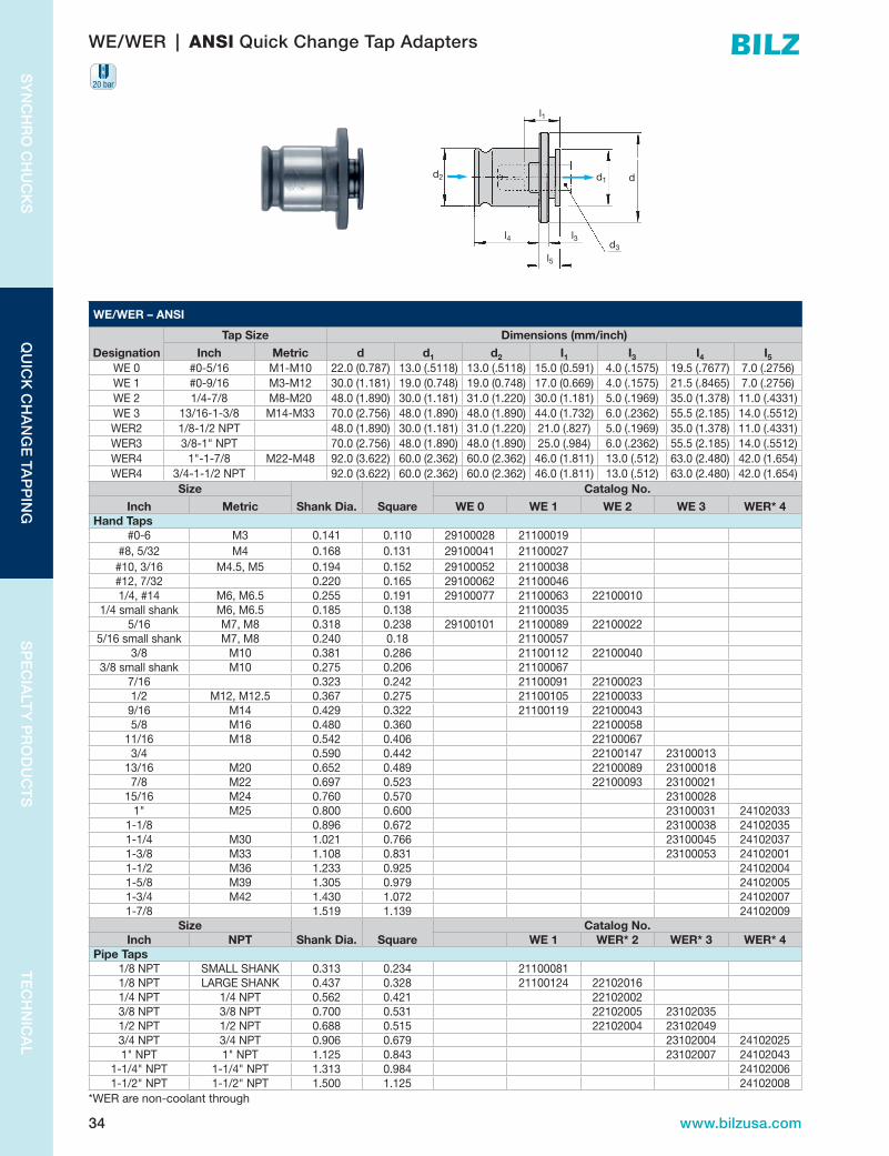
WE/WER – ANSI
Designation
Tap Size Dimensions (mm/inch)
Inch Metric d d1 d2 I1 I3 I4 I5WE 0 #0-5/16 M1-M10 22.0(0.787) 13.0(.5118) 13.0(.5118) 15.0(0.591) 4.0(.1575) 19.5(.7677) 7.0(.2756)WE1 #0-9/16 M3-M12 30.0(1.181) 19.0(0.748) 19.0(0.748) 17.0(0.669) 4.0(.1575) 21.5(.8465) 7.0(.2756)WE2 1/4-7/8 M8-M20 48.0(1.890) 30.0(1.181) 31.0(1.220) 30.0(1.181) 5.0(.1969) 35.0(1.378) 11.0(.4331)WE3 13/16-1-3/8 M14-M33 70.0(2.756) 48.0(1.890) 48.0(1.890) 44.0(1.732) 6.0(.2362) 55.5(2.185) 14.0(.5512)WER2 1/8-1/2NPT 48.0(1.890) 30.0(1.181) 31.0(1.220) 21.0(.827) 5.0(.1969) 35.0(1.378) 11.0(.4331)WER3 3/8-1"NPT 70.0(2.756) 48.0(1.890) 48.0(1.890) 25.0(.984) 6.0(.2362) 55.5(2.185) 14.0(.5512)WER4 1"-1-7/8 M22-M48 92.0(3.622) 60.0(2.362) 60.0(2.362) 46.0(1.811) 13.0(.512) 63.0(2.480) 42.0(1.654)WER4 3/4-1-1/2NPT 92.0(3.622) 60.0(2.362) 60.0(2.362) 46.0(1.811) 13.0(.512) 63.0(2.480) 42.0(1.654)
Size
Shank Dia. Square
Catalog No.
Inch Metric WE 0 WE 1 WE 2 WE 3 WER* 4Hand Taps
#0-6 M3 0.141 0.110 29100028 21100019#8,5/32 M4 0.168 0.131 29100041 21100027#10,3/16 M4.5,M5 0.194 0.152 29100052 21100038#12,7/32 0.220 0.165 29100062 211000461/4,#14 M6,M6.5 0.255 0.191 29100077 21100063 22100010
1/4smallshank M6,M6.5 0.185 0.138 211000355/16 M7,M8 0.318 0.238 29100101 21100089 22100022
5/16smallshank M7,M8 0.240 0.18 211000573/8 M10 0.381 0.286 21100112 22100040
3/8smallshank M10 0.275 0.206 211000677/16 0.323 0.242 21100091 221000231/2 M12,M12.5 0.367 0.275 21100105 221000339/16 M14 0.429 0.322 21100119 221000435/8 M16 0.480 0.360 22100058
11/16 M18 0.542 0.406 221000673/4 0.590 0.442 22100147 23100013
13/16 M20 0.652 0.489 22100089 231000187/8 M22 0.697 0.523 22100093 23100021
15/16 M24 0.760 0.570 231000281" M25 0.800 0.600 23100031 24102033
1-1/8 0.896 0.672 23100038 241020351-1/4 M30 1.021 0.766 23100045 241020371-3/8 M33 1.108 0.831 23100053 241020011-1/2 M36 1.233 0.925 241020041-5/8 M39 1.305 0.979 241020051-3/4 M42 1.430 1.072 241020071-7/8 1.519 1.139 24102009
SizeShank Dia. Square
Catalog No.Inch NPT WE 1 WER* 2 WER* 3 WER* 4
Pipe Taps1/8NPT SMALLSHANK 0.313 0.234 211000811/8NPT LARGESHANK 0.437 0.328 21100124 221020161/4NPT 1/4NPT 0.562 0.421 221020023/8NPT 3/8NPT 0.700 0.531 22102005 231020351/2NPT 1/2NPT 0.688 0.515 22102004 231020493/4NPT 3/4NPT 0.906 0.679 23102004 241020251"NPT 1"NPT 1.125 0.843 23102007 24102043
1-1/4"NPT 1-1/4"NPT 1.313 0.984 241020061-1/2"NPT 1-1/2"NPT 1.500 1.125 24102008
*WERarenon-coolantthrough
WE/WER | ANSI Quick Change Tap Adapters
l4
d
l3
l1
l5
d1d2
d3
20 bar

35www.bilzusa.com
TE
CH
NIC
AL
SP
EC
IALT
Y P
RO
DU
CT
SQ
UIC
K C
HA
NG
E T
AP
PIN
GS
YN
CH
RO
CH
UC
KS
SY
NC
HR
O C
HU
CK
S
WE KP – ANSI
Tap Size Dimensions (mm/inch)
Designation Inch Metric d d1 d2 I1 I3 I4 I5WE1KP #0-9/16 M3-M12 30.0(1.181) 19.0(0.748) 19.0(0.748) 17.0(0.669) 4.0(.1575) 21.5(.8465) 7.0(.2756)
WE2KP 1/4-7/8 M8-M20 48.0(1.890) 30.0(1.181) 31.0(1.220) 30.0(1.181) 5.0(.1969) 35.0(1.378) 11.0(.4331)
WE3KP 13/16-1-3/8 M14-M33 70.0(2.756) 48.0(1.890) 48.0(1.890) 44.0(1.732) 6.0(.2362) 55.5(2.185) 14.0(.5512)
WER2KP 1/8-1/2NPT 48.0(1.890) 30.0(1.181) 31.0(1.220) 21.0(.827) 5.0(.1969) 35.0(1.378) 11.0(.4331)
WER3KP 3/8-1"NPT 70.0(2.756) 48.0(1.890) 48.0(1.890) 25.0(.984) 6.0(.2362) 55.5(2.185) 14.0(.5512)Size
Shank Dia. Square
Catalog No.
Inch Metric WE 1 KP WE 2 KP WE 3 KPHand Taps
#0-6 M3 0.141 0.110 21184032
#8,5/32 M4 0.168 0.131 21184031
#10,3/16 M4.5,M5 0.194 0.152 21184029
#12,7/32 #12 0.220 0.165 21184036
1/4,#14 M6,M6.5 0.255 0.191 21184019
5/16 M7,M8 0.318 0.238 21184020 22167430
3/8 M10 0.381 0.286 21184021 22167424
7/16 0.323 0.242 21184022 22167433
1/2 M12,M12.5 0.367 0.275 21184023 22167418
9/16 M14 0.429 0.322 22167428
5/8 M16 0.480 0.360 22167419
11/16 M18 0.542 0.406 22167438
3/4 0.590 0.442 22167420
13/16 M20 0.652 0.489 22167436 23156430
7/8 M22 0.697 0.523 22167434 23156419
15/16 M24 0.760 0.570 23156429
1" M25 0.800 0.600 23156420
1-1/8 0.896 0.672 23156436
1-1/4 M30 1.021 0.766 23156434
1-3/8 M33 1.108 0.831 23156430
SizeShank Dia. Square
Catalog No.Inch NPT WE 1 KP WER 2 KP WER 3 KP
Pipe Taps1/8NPT SMALLSHANK 0.3125 0.234 21184035
1/8NPT LARGESHANK 0.437 0.328 21184030
1/4NPT 1/4NPT 0.562 0.421 22185402
3/8NPT 3/8NPT 0.7 0.531 22185405 23157435
1/2NPT 1/2NPT 0.6875 0.515 22185404 23157436
3/4NPT 3/4NPT 0.906 0.679 23157404
1"NPT 1"NPT 1.125 0.843 23157407
WE KP (Slotted) | ANSI Quick Change Tap Adapters
d1
d3l5
l3l4
l1
dd2
20 bar
36 www.bilzusa.com
SY
NC
HR
O C
HU
CK
SQ
UIC
K C
HA
NG
E TA
PP
ING
SP
EC
IALT
Y P
RO
DU
CT
ST
EC
HN
ICA
L
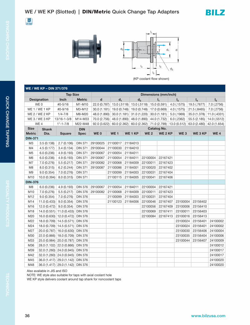
WE / WE KP – DIN 371/376
Tap Size Dimensions (mm/inch)
Designation Inch Metric d d1 d2 I1 I3 I4 I5WE 0 #0-5/16 M1-M10 22.0(0.787) 13.0(.5118) 13.0(.5118) 15.0(0.591) 4.0(.1575) 19.5(.7677) 7.0(.2756)
WE1/WE1KP #0-9/16 M3-M12 30.0(1.181) 19.0(0.748) 19.0(0.748) 17.0(0.669) 4.0(.1575) 21.5(.8465) 7.0(.2756)
WE2/WE2KP 1/4-7/8 M8-M20 48.0(1.890) 30.0(1.181) 31.0(1.220) 30.0(1.181) 5.0(.1969) 35.0(1.378) 11.0(.4331)
WE3/WE3KP 13/16-1-3/8 M14-M33 70.0(2.756) 48.0(1.890) 48.0(1.890) 44.0(1.732) 6.0(.2362) 55.5(2.185) 14.0(.5512)
WE 4 1"-1-7/8 M22-M48 92.0(3.622) 60.0(2.362) 60.0(2.362) 71.0(2.799) 13.0(0.512) 63.0(2.480) 42.0(1.654)
WE / WE KP (Slotted) | DIN/Metric Quick Change Tap Adapters
Size Shank Dia. Square
DIN Spec
Catalog No.
Metric WE 0 WE 1 WE 1 KP WE 2 WE 2 KP WE 3 WE 3 KP WE 4DIN-371M3 3.5(0.138) 2.7(0.106) DIN371 29100025 21100017 21184013
M4 4.5(0.177) 3.4(0.134) DIN371 29100044 21100030 21184010
M5 6.0(0.236) 4.9(0.193) DIN371 29100067 21100054 21184011
M6 6.0(0.236) 4.9(0.193) DIN371 29100067 21100054 21184011 22100004 22167421
M7 7.0(0.276) 5.5(0.217) DIN371 29100082 21100068 21184009 22100011 22167423
M8 8.0(0.315) 6.2(0.244) DIN371 29100087 21100086 21184001 22100020 22167402
M9 9.0(0.354) 7.0(0.276) DIN371 21100099 21184003 22100031 22167404
M10 10.0(0.394) 8.0(0.315) DIN371 21100115 21184005 22100041 22167406
DIN-376M8 6.0(0.236) 4.9(0.193) DIN376 29100067 21100054 21184011 22100004 22167421
M10 7.0(0.276) 5.5(0.217) DIN376 29100082 21100068 21184009 22100011 22167423
M12 9.0(0.354) 7.0(0.276) DIN376 21100099 21184003 22100031 22167404
M14 11.0(0.433) 9.0(0.354) DIN376 21100123 21184006 22100046 22167407 23100004 23156402
M16 12.0(0.472) 9.0(0.354) DIN376 22100056 22167409 23100006 23156410
M18 14.0(0.551) 11.0(0.433) DIN376 22100069 22167411 23100011 23156403
M20 16.0(0.630) 12.0(0.472) DIN376 22100084 22167413 23100016 23156413
M22 18.0(0.709) 14.5(0.571) DIN376 23100024 23156401 24100002
M24 18.0(0.709) 14.5(0.571) DIN376 23100024 23156401 24100002
M27 20.0(0.787) 16.0(0.630) DIN376 23100030 23156406 24100004
M30 22.0(0.866) 18.0(0.709) DIN376 23100035 23156404 24100006
M33 25.0(0.984) 20.0(0.787) DIN376 23100044 23156407 24100009
M36 28.0(1.102) 22.0(0.866) DIN376 24100012
M39 32.0(1.260) 24.0(0.945) DIN376 24100017
M42 32.0(1.260) 24.0(0.945) DIN376 24100017
M45 36.0(1.417) 29.0(1.142) DIN376 24100020
M48 36.0(1.417) 29.0(1.142) DIN376 24100020
Also available in JIS and ISONOTE: WE style also suitable for taps with axial coolant holeWE KP style delivers coolant around tap shank for noncoolant taps
l4
d
l3
l1
l5
d1d2
d3
20 bar
(KP coolant flow shown)

37www.bilzusa.com
TE
CH
NIC
AL
SP
EC
IALT
Y P
RO
DU
CT
SQ
UIC
K C
HA
NG
E T
AP
PIN
GS
YN
CH
RO
CH
UC
KS
Square & Shank Dimensions
ANSI Shank Metric Shank
metric thread, ANSI shank Tap #
fract. Dia
inch shank
dia.inch
squaredia
[mm]square [mm]
inch snank
dia.inch
squaredia
[mm]square [mm]
DIN352 hand tap
shortDIN353
inch
DIN371 strong shank
DIN376 DIN374 normal +fine
DIN2182 normal
inch
DIN2183 out of range inch ISO 529 JIS
JIS inch
M1.6 0 0.141 0.110 3.58 2.79 0.098 0.083 2.5 2.1 M1 M1 M3.5 1/16" 1/16"M1.8 1 0.141 0.110 3.58 2.79 0.098 0.083 2.5 2.1 M1.1 M1.1
M2,M2.2 2 0.141 0.110 3.58 2.79 0.098 0.083 2.5 2.1 M1.2 M1.2M2.5 3 0.141 0.110 3.58 2.79 0.098 0.083 2.5 2.1 M1.4 M1.4
4 0.141 0.110 3.58 2.79 0.098 0.083 2.5 2.1 M1.6 M1.6M3,M3.15 5 1/8" 0.141 0.110 3.58 2.79 0.098 0.083 2.5 2.1 M1.8 M1.8
M3.5 6 0.141 0.110 3.58 2.79 0.110 0.083 2.8 2.1 M2 M2 M4 3/32" 5/32"7 0.168 0.130 4.26 3.3 0.110 0.083 2.8 2.1 M2.2 M2.2
M4 8 5/32" 0.168 0.130 4.26 3.3 0.110 0.083 2.8 2.1 M2.5 M2.59 0.194 0.152 4.93 3.86 0.110 0.088 2.8 2.24 M2.5
M5 10 3/16" 0.194 0.152 4.93 3.86 0.118 0.098 3 2.5 M2.5 #312 7/32" 0.220 0.165 5.59 4.19 0.124 0.098 3.15 2.5 #8
M6,M6.3 14 1/4" 0.247 0.185 6.27 4.7 0.124 0.110 3.15 2.8 #416 0.273 0.205 6.93 5.2 0.138 0.106 3.5 2.7 M3 M3 M5 1/8"18 0.299 0.225 7.59 5.71 0.140 0.110 3.55 2.8 #620 0.325 0.244 8.25 6.2 0.157 0.118 4 3 M3.5 M3.5#6 7/32"
5/32" 0.160 0.122 4.06 3.1 0.157 0.126 4 3.2 M3 #5,#63/16" 0.192 0.149 4.88 3.78 0.177 0.134 4.5 3.4 M4 M4 M6 5/32" 1/4"7/32" 0.223 0.167 5.66 4.24 0.197 0.157 5 4 #10 M4,M5 #8
1/4" 0.255 0.191 6.48 4.85 0.217 0.177 5.5 4.5 M5,M5.5 #10
9/32" 0.286 0.214 7.26 5.44 0.220 0.177 5.6 4.5 #12M7,M8 5/16" 0.318 0.238 8.08 6.05 0.236 0.177 6 4.5 M6 1/4"-20
11/32" 0.349 0.262 8.86 6.65 0.236 0.193 6 4.9 M5 M5M10 3/8" 0.381 0.286 9.68 7.26 0.236 0.193 6 4.9 M6,M8 M6 M8
13/32" 0.323 0.242 8.20 6.15 0.240 0.197 6.1 5 M6
7/16" 0.323 0.242 8.20 6.15 0.244 0.197 6.2 5 M8,M7 5/16"-18
15/32" 0.354 0.265 8.99 6.73 0.248 0.197 6.3 5 1/4"-20
M12,M12.5 1/2" 0.367 0.275 9.32 6.99 0.276 0.217 7 5.5 M10 G1/8" M10 1/4" 3/8" M10,M9
17/32" 0.398 0.298 10.11 7.57 0.315 0.236 8 6 M11 1/8"M14 9/16" 0.429 0.322 10.90 8.18 0.315 0.244 8 6.2 M8 5/16" 7/16"
19/32" 0.460 0.345 11.68 8.76 0.315 0.248 8 6.3 5/16"-18
M16 5/8" 0.480 0.360 12.19 9.14 0.335 0.256 8.5 6.5 M1221/32" 0.511 0.383 12.98 9.73 0.354 0.276 9 7 M12 3/8" 1/2" M12
M18 11/16" 0.542 0.406 13.77 10.31 0.394 0.315 10 8 M10
23/32" 0.573 0.430 14.55 10.92 0.413 0.315 10.5 8 M14,M15
3/4" 0.590 0.442 14.99 11.23 0.433 0.354 11 9 M14 G1/4" M14 9/16" 1/4"
25/32" 0.621 0.466 15.77 11.84 0.472 0.354 12 9 M16 G3/8" M16 5/8" M14,M15
M20 13/16" 0.652 0.489 16.56 12.42 0.492 0.394 12.5 10 M16 M1627/32" 0.684 0.513 17.37 13.03 0.512 0.394 13 10 M17
M22 7/8" 0.697 0.523 17.70 13.28 0.551 0.433 14 11 M18 M18 11/16" M18 3/8"0.551 0.441 14 11.2 M18
M24 15/16" 0.760 0.570 19.30 14.48 0.591 0.472 15 12 M20M25 1" 0.800 0.600 20.32 15.24 0.630 0.472 16 12 M20 G1/2" M20 13/16"M27 1-1/16" 0.862 0.646 21.89 16.41 0.669 0.512 17 13 M22
1-1/8" 0.896 0.672 22.76 17.07 0.709 0.551 18 14 1/2"M30 1-3/16" 0.959 0.719 24.36 18.26 0.709 0.571 18 14.5 M22 G5/8" M22 7/8"
1-1/4" 1.021 0.766 25.93 19.46 0.709 0.571 18 14.5 M24 M24 15/16"
M33 1-5/16" 1.084 0.813 27.53 20.65 0.748 0.591 19 15 M24,M25
1/2"NPT
1-3/8" 1.108 0.831 28.14 21.11 0.787 0.591 20 15 M27,M26
M36 1-7/16" 1.171 0.878 29.74 22.3 0.787 0.630 20 16 M27 G3/4" M27 1"1-1/2" 1.233 0.925 31.32 23.5 0.827 0.669 21 17 M28
M39 1-5/8" 1.305 0.979 33.15 24.87 0.866 0.669 22 17 M28M42 1-3/4" 1.430 1.072 36.32 27.23 0.866 0.709 22 18 M30 G7/8" M30 1-1/8"
1-7/8" 1.519 1.139 38.58 28.93 0.906 0.669 23 17 M30 3/4"M48 2" 1.644 1.233 41.76 31.32 0.945 0.748 24 19 M32 3/4"NPT
Pulley Taps0.984 0.748 25 19 M330.984 0.787 25 20 M33 G1" M33 1-1/4"
M6 1/4" 0.255 0.191 6.48 4.85 1.024 0.827 26 21 M35,M34 1"
M8 5/16" 0.318 0.238 8.08 6.04 1.102 0.827 28 21 M36,M38 1"NPT
M10 3/8" 0.381 0.286 9.68 7.26 1.102 0.866 28 22 M36 G1-1/8" M36 1-3/8"7/16" 0.444 0.333 11.28 8.46 1.102 0.882 28 22.4
1/2" 0.504 0.380 12.80 9.65 1.181 0.906 30 23 M39,M40
5/8" 0.633 0.475 16.08 12.06 1.260 0.945 32 24 M39 G1-1/4" M39 1-1/2"3/4" 0.756 0.569 19.20 14.45 1.260 0.945 32 24 M42 G1-1/4" M42 1-5/8"
Pipe Taps1.260 1.024 32 26 M42 1-1/4"1.378 1.024 35 26 M45 1-3/8"
1/8"SS 0.313 0.234 7.94 5.94 1.417 1.142 36 29 M45 G1-3/8" M45 1-3/4"1/8"LS 0.437 0.328 11.11 8.33 1.417 1.142 36 29 M48 G1-1/2" M48 1-7/8"1/4" 0.563 0.421 14.29 10.69 1.417 1.142 36 29 G1-3/4"3/8" 0.700 0.531 17.78 13.49 1.417 1.142 36 29 G2"1/2" 0.687 0.515 17.46 13.08 1.496 1.142 38 29 M48 1-1/2"5/8" 0.813 0.594 20.64 15.09 1.575 1.260 40 32 M52 G2-1/4" M52 2"3/4" 0.906 0.679 23.02 17.25 1.772 1.378 45 35 M56 G2-1/2" M56 2-1/4"7/8" 1.094 0.812 27.78 20.62 1.772 1.378 45 35 M60 M60 2-1/2"1" 1.125 0.843 28.57 21.41 1.969 1.535 50 39 M64 G2-3/4" M64 2-1/2"
1-1/4" 1.313 0.984 33.34 24.99 1.969 1.535 50 39 G3"1-3/8" 1.108 0.831 28.14 21.11 2.205 1.732 56 44 M68 G3-1/4" M68 2-3/4"1-1/2" 1.500 1.125 38.10 28.57 2.205 1.732 56 44 3"

38 www.bilzusa.com
SY
NC
HR
O C
HU
CK
SQ
UIC
K C
HA
NG
E TA
PP
ING
SP
EC
IALT
Y P
RO
DU
CT
ST
EC
HN
ICA
L
WES / WESR | ANSI Torque Control Quick Change Tap Adapters
WES / WESR – ANSI
Tap Size Dimensions (mm/inch)
Designation Inch Metric d d1 d2 I1 I3 I4 I5WES 0B #0-5/16 M1-M10 23.0(0.906) 13.0(.5118) 13.0(.5118) 15.0(0.591) 20.0(.7874) 19.5(.7677) 21.0(0.827)WES1B #0-9/16 M3-M12 32.0(1.259) 19.0(0.748) 19.0(0.748) 17.0(0.669) 25.0(.9843) 21.5(.8465) 25.0(0.984)WES2B 1/4-7/8 M8-M20 50.0(1.969) 30.0(1.181) 31.0(1.220) 30.0(1.181) 31.0(1.220) 35.0(1.378) 34.0(1.339)WES3B 13/16-1-3/8 M14-M33 72.0(2.835) 48.0(1.890) 48.0(1.890) 44.0(1.732) 41.0(1.614) 55.5(2.185) 45.0(1.772)WESR2B 1/8-1/2NPT 50.0(1.969) 30.0(1.181) 31.0(1.220) 21.0(0.827) 31.0(1.220) 35.0(1.378) 34.0(1.339)WESR3B 3/8-1"NPT 72.0(2.835) 48.0(1.890) 48.0(1.890) 25.0(0.984) 41.0(1.614) 55.5(2.185) 45.0(1.772)WESR 4B 1"-1-7/8 M22-M48 95.0(3.740) 60.0(2.362) 60.0(2.362) 46.0(1.811) 61.0(2.402) 63.0(2.480) 68.0(2.677)WESR 4B 3/4-1-1/2NPT 95.0(3.740) 60.0(2.362) 60.0(2.362) 46.0(1.811) 61.0(2.402) 63.0(2.480) 68.0(2.677)
Size Shank Dia. Square
Catalog No.Inch Metric WES 0 WES 1 WES 2 WES 3 WESR* 4B
Hand Taps#0-6 M3 0.141 0.11 29200028 21200019
#8,5/32 M4 0.168 0.131 29200041 21200027#10,3/16 M4.5,M5 0.194 0.152 29200052 21200038#12,7/32 #12 0.22 0.165 29200062 21200046#14,1/4 M6,M6.5 0.255 0.191 29200077 21200063 222000105/16 M7,M8 0.318 0.238 29200101 21200089 222000223/8 M10 0.381 0.286 21200112 222000407/16 7/16 0.323 0.242 21200091 222000231/2 M12,M12.5 0.367 0.275 21200105 222000339/16 M14 0.429 0.322 21200119 222000435/8 M16 0.48 0.36 22200058
11/16 M18 0.542 0.406 222000673/4 3/4 0.59 0.442 22200147 23200040
13/16 M20 0.652 0.489 22200089 232000187/8 M22 0.697 0.523 22200093 23200021
15/16 M24 0.76 0.57 232000281" M25 0.8 0.6 23200031 24602033
1-1/8 0.896 0.672 23200038 246020351-1/4 1.021 0.766 23200045 246020371-3/8 1.108 0.831 23200053 246020011-1/2 1.233 0.925 246020041-5/8 1.305 0.979 246020051-3/4 1.430 1.072 246020071-7/8 1.519 1.139 24602009
Size Shank Dia. Square
Catalog No.Inch Metric WES 0 WES 1 WESR* 2 WESR* 3 WESR* 4B
Pipe Taps1/8NPT SMALLSHANK 0.3125 0.234 212000811/8NPT LARGESHANK 0.437 0.328 21200124 222000481/4NPT 1/4NPT 0.562 0.421 226020023/8NPT 3/8NPT 0.7 0.531 22602005 236020351/2NPT 1/2NPT 0.6875 0.515 22602004 236020363/4NPT 3/4NPT 0.906 0.679 23602004 246020251"NPT 1"NPT 1.125 0.843 23602007 24602043
1-1/4NPT 1-1/4NPT 1.313 0.984 246020061-1/2NPT 1-1/2NPT 1.500 1.125 24602008
NOTE: WES style also suitable for taps with axial coolant hole. *WESRarenon-coolantthrough
d1
d3l5
l3l4
l1
dd2
20 bar

39www.bilzusa.com
TE
CH
NIC
AL
SP
EC
IALT
Y P
RO
DU
CT
SQ
UIC
K C
HA
NG
E T
AP
PIN
GS
YN
CH
RO
CH
UC
KS
WES | DIN/Metric Torque Control Quick Change Tap Adapters
WES – DIN 371/376
Tap Size Dimensions (mm/inch)
Designation Inch Metric d d1 d2 I1 I3 I4 I5WES 0B #0-5/16 M1-M10 23.0(0.906) 13.0(0.5118) 13.0(0.5118) 15.0(0.591) 20.0(0.7874) 19.5(0.7677) 21.0(0.827)
WES1B #0-9/16 M3-M12 32.0(1.259) 19.0(0.748) 19.0(0.748) 17.0(0.669) 25.0(0.9843) 21.5(0.8465) 25.0(0.984)
WES2B 1/4-7/8 M8-M20 50.0(1.969) 30.0(1.181) 31.0(1.220) 30.0(1.181) 31.0(1.220) 35.0(1.378) 34.0(1.339)
WES3B 13/16-1-3/8 M14-M33 72.0(2.835) 48.0(1.890) 48.0(1.890) 44.0(1.732) 41.0(1.614) 55.5(2.185) 45.0(1.772)
WES 4B 1"-1-7/8 M22-M48 95.0(3.740) 60.0(2.362) 60.0(2.362) 71.0(2.795) 61.0(2.402) 63.0(2.480) 68.0(2.677)Size Shank
Dia. SquareDIN
Spec
Catalog No.
Metric WES 0 WES 1 WES 2 WES 3 WES 4DIN-371
M3 3.5(0.138) 2.7(0.106) DIN371 29201025 21200017
M4 4.5(0.177) 3.4(0.134) DIN371 29201044 21200030
M5 6.0(0.236) 4.9(0.193) DIN371 29201067 21201054
M6 6.0(0.236) 4.9(0.193) DIN371 29202067 21202054 22201004
M7 7.0(0.276) 5.5(0.217) DIN371 29201082 21201068 22201011
M8 8.0(0.315) 6.2(0.244) DIN371 29201087 21201086 22201020
M9 9.0(0.354) 7.0(0.276) DIN371 21201099 22201031
M10 10.0(0.394) 8.0(0.315) DIN371 21201115 22201041
DIN-376M8 6.0(0.236) 4.9(0.193) DIN376 29201067 21203054 22202004
M10 7.0(0.276) 5.5(0.217) DIN376 29201082 21201068 22201011
M12 9.0(0.354) 7.0(0.276) DIN376 21201099 22201031
M14 11.0(0.433) 9.0(0.354) DIN376 21201123 22201046 23201004
M16 12.0(0.472) 9.0(0.354) DIN376 22201056 23201006
M18 14.0(0.551) 11.0(0.433) DIN376 22201069 23201011
M20 16.0(0.630) 12.0(0.472) DIN376 22201084 23201016
M22 18.0(0.7087) 14.5(0.5709) DIN376 22201097 23201024 24201002
M24 18.0(0.7087) 14.5(0.5709) DIN376 22202097 23202024 24202002
M27 20.0(0.7874) 16.0(0.6299) DIN376 23201030 24600004
M30 22.0(0.8661) 18.0(0.7087) DIN376 23201035 24600006
M33 25.0(0.9843) 20.0(0.7874) DIN376 23201044 24600009
M36 28.0(1.102) 22.0(0.866) DIN376 24600012
M39 32.0(1.260) 24.0(0.945) DIN376 24201017
M42 32.0(1.260) 24.0(0.945) DIN376 24202017
M45 36.0(1.417) 29.0(1.142) DIN376 24201020
M48 36.0(1.417) 29.0(1.142) DIN376 24202020
Also available in JIS and ISONOTE: WES style also suitable for taps with axial coolant hole.
d1
d3l5
l3l4
l1
dd2
20 bar

40 www.bilzusa.com
SY
NC
HR
O C
HU
CK
SQ
UIC
K C
HA
NG
E TA
PP
ING
SP
EC
IALT
Y P
RO
DU
CT
ST
EC
HN
ICA
L
WEN / WEN KP – ANSI
Tap Size Dimensions (mm/inch)
Designation Inch d d1 d2 I1 I3 I4 I5 N N (KP)WEN 0 #0-5/16 22.0(0.787) 13.0(.5118) 13.0(.5118) 15.0(0.591) 4.0(.1575) 19.5(.7677) 29.0(1.142) 8.0(.3150) NA
WEN1/WEN1KP #0-9/16 30.0(1.181) 19.0(0.748) 19.0(0.748) 17.0(0.669) 4.0(.1575) 21.5(.8465) 34.0(1.339) 10.0(.3937) 6.5(0.256)
WEN2/WEN2KP 1/4-7/8 48.0(1.890) 30.0(1.181) 31.0(1.220) 30.0(1.181) 5.0(.1969) 35.0(1.378) 60.0(2.362) 15.0(.5906) 10.0(0.551)
WEN3/WEN3KP 13/16-1-3/8 70.0(2.756) 48.0(1.890) 48.0(1.890) 44.0(1.732) 6.0(.2362) 55.5(2.185) 83.0(3.267) 25.0(.9843) 25.0(.9843)
WENR2/WENRKP 1/8-1/2NPT 48.0(1.890) 30.0(1.181) 31.0(1.220) 30.0(0.827) 5.0(.1969) 35.0(1.378) 60.0(2.362) 15.0(.5906) 10.0(0.551)
WENR3 3/8-1"NPT 70.0(2.756) 48.0(1.890) 48.0(1.890) 44.0(0.984) 6.0(.2362) 55.5(2.185) 83.0(3.267) 25.0(.9843) 25.0(.9843)
Size Shank Dia. Square
Catalog No.
Inch Metric WEN 0 WEN 1 WEN 1 KP WEN 2 WEN 2 KP WEN 3Hand Taps
#0-6 M3 0.141 0.11 29300028 21300019 21369432
#8,5/32 M4 0.168 0.131 29300041 21300027 21369431
#10,3/16 M4.5,M5 0.194 0.152 29300052 21300038 21369429
#12,7/32 0.220 0.165 29300062 21300046 21369036
1/4,#14 M6,M6.5 0.255 0.191 29300077 21300063 21369419 22300010
5/16 M7,M8 0.318 0.238 29300101 21300089 21369420 22300022 22367430
3/8 M10 0.381 0.286 21300112 21369421 22300040 22367424
7/16 0.323 0.242 21300091 21369422 22300023 22367433
1/2 M12,M12.5 0.367 0.275 21300105 21369423 22300033 22367418
9/16 M14 0.429 0.322 21300119 21369424 22300043 22367428
5/8 M16 0.480 0.36 22300058 22367419
11/16 M18 0.542 0.406 22300067 22367438
3/4 0.590 0.442 22300147 22367420
13/16 M20 0.652 0.489 22300089 22367436 23300018
39636 M22 0.697 0.523 22300093 22367434 23300021
15/16 M24 0.760 0.57 23300028
1" M25 0.800 0.6 23300031
1-1/8 0.896 0.672 23300038
1-1/4 M30 1.021 0.766 23300045
1-3/8 M33 1.108 0.831 23300053Size
Shank Dia. SquareCatalog No.
Inch Metric WEN 1 WEN 1 KP WENR* 2 WENR 2 KP WENR* 3Pipe Taps
1/8NPT SMALLSHANK 0.3125 0.234 21300081 21369430
1/8NPT LARGESHANK 0.437 0.328 21300124 21369435 22302016
1/4NPT 1/4NPT 0.562 0.421 22302002
3/8NPT 3/8NPT 0.700 0.531 22302005 23302035
1/2NPT 1/2NPT 0.688 0.515 22302004 22302804 23302049
3/4NPT 3/4NPT 0.906 0.679 23302004
1"NPT 1"NPT 1.125 0.843 23302007
NOTE: WEN also suitable for taps with axial coolant holeWEN KP style delivers coolant around tap shank for non-coolant taps*WENRarenon-coolantthrough
l4
d
l3
l1
l5
d1d2
d3
NN (IKP)
20 bar
(KP coolant flow shown)
WEN / WEN KP (Slotted) | ANSI Quick Change Adjustable Length Tap Adapters

41www.bilzusa.com
TE
CH
NIC
AL
SP
EC
IALT
Y P
RO
DU
CT
SQ
UIC
K C
HA
NG
E T
AP
PIN
GS
YN
CH
RO
CH
UC
KS
WEN / WEN KP – DIN 371/376
Tap Size Dimensions (mm/inch)
Designation Metric d d1 d2 I1 I3 I4 I5 N N (KP)WEN 0 M1-M10 22.0(0.787) 13.0(.5118) 13.0(.5118) 15.0(0.591) 4.0(.1575) 19.5(.7677) 7.0(.2756) 8.0(.3150) NA
WEN1/WEN1KP M3-M12 30.0(1.181) 19.0(0.748) 19.0(0.748) 17.0(0.669) 4.0(.1575) 21.5(.8465) 7.0(.2756) 10.0(.3937) 6.5(0.256)
WEN2/WEN2KP M8-M20 48.0(1.890) 30.0(1.181) 31.0(1.220) 30.0(1.181) 5.0(.1969) 35.0(1.378) 11.0(.4331) 15.0(.5906) 10.0(0.551)
WEN3 M14-M33 70.0(2.756) 48.0(1.890) 48.0(1.890) 44.0(1.732) 6.0(.2362) 55.5(2.185) 14.0(.5512) 25.0(.9843) 25.0(.9843)
Size Shank Dia. Square
DIN Spec
Catalog No.
Metric WEN 0 WEN 1 WEN 1 KP WEN 2 WEN 2 KP WEN 3Hand Taps
M3 3.5(0.138) 2.7(0.106) DIN371 29300025 21300017
M4 4.5(0.177) 3.4(0.134) DIN371 29300044 21300030
M5 6.0(0.236) 4.9(0.193) DIN371 29300067 21300054 21369411 22300004
M6 6.0(0.236) 4.9(0.193) DIN371 29300067 21300054 21369411 22300004 22367021
M7 7.0(0.276) 5.5(0.217) DIN371 29300082 21300068 21369409 22300011 22367023
M8 8.0(0.315) 6.2(0.244) DIN371 29300087 21300086 21369401 22300020 22367002
M9 9.0(0.354) 7.0(0.276) DIN371 21300099 21369403 22300031 22367004
M10 10.0(0.394) 8.0(0.315) DIN371 21300115 21369405 22300041 22367406
Pipe TapsM8 6.0(0.236) 4.9(0.193) DIN376 29300067 21300054 21369411 22300004 22367021
M10 7.0(0.276) 5.5(0.217) DIN376 29300082 21300068 21369409 22300011 22367023
M12 9.0(0.354) 7.0(0.276) DIN376 21300099 21369403 22300031 22367004
M14 11.0(0.433) 9.0(0.354) DIN376 21300123 21369406 22300046 22367407 23300004
M16 12.0(0.472) 9.0(0.354) DIN376 22300056 22367009 23300006
M18 14.0(0.551) 11.0(0.433) DIN376 22300069 22367411 23300011
M20 16.0(0.630) 12.0(0.472) DIN376 22300084 22367013 23300016
M22 18.0(0.709) 14.5(0.571) DIN376 22300097 22367016 23300024
M24 18.0(0.709) 14.5(0.571) DIN376 22300097 22367016 23300024
M27 20.0(0.787) 16.0(0.630) DIN376 23300030
M30 22.0(0.866) 18.0(0.709) DIN376 23300035
M33 25.0(0.984) 20.0(0.787) DIN376 23300044
NOTE: WEN also suitable for taps with axial coolant holeWEN KP style delivers coolant around tap shank for non-coolant taps
l4
d
l3
l1
l5
d1d2
d3
NN (IKP)
20 bar
(KP coolant flow shown)
WEN / WEN KP (Slotted) | DIN/Metric Quick Change Adjustable Length Tap Adapters

42 www.bilzusa.com
SY
NC
HR
O C
HU
CK
SQ
UIC
K C
HA
NG
E TA
PP
ING
SP
EC
IALT
Y P
RO
DU
CT
ST
EC
HN
ICA
L
WEN | Quick Change Adjustable Length Tap Adapters
d1
d3l 5
l 3l 4
l 1 N
dd2
WEN-V – Extended Length Adjustable Adapters
– +
N
Designation d3 d d1 d2 I1 I3 I4 I5WEN0-… M1–M10 2.5-7.2 0 8 22 13 13 15 4 19.5 40 50 60 70 80 90 100 110 120WEN1-… M3–M12 3.5-11.3 1 10 30 19 19 17 4 21.5 40 50 60 70 80 90 100 110 120 130 140WEN2-… M8–M20 7.0-18 2 15 48 31 31 30 5 35 70 80 90 100 110 120 130 140 150 160WEN3-… M14–M33 11-28 3 25 70 48 48 44 6 55.5 100 120 140 160 180WEN40-… M6–M18 6.0-14 40 15 40 25 26 30 5 32 60 70 80 90 100 110 120 130 140 150
ExamplefororderingWEN1-80thentapsize
WEN-V-KP – Extended Length Adjustable Adapters
– +
N
Designation d3 d d1 d2 I1 I3 I4 I5WEN1-KP… M3–M12 3.5-11.3 1 6.5 30 19 19 17 4 21.5 40 50 60 70 80 90 100 110 120 130 140WEN2-KP… M8–M20 7.0-18 2 14 48 30 31 30 5 35 70 80 90 100 110 120 130 140 150 160WEN3-KP… M14–M33 11-28 3 25 70 48 48 44 6 55.5 100 120 140 160 180
ExamplefororderingWEN2-KP-120thentapsize
WEN-V-IKP – Extended Length Adjustable Adapters – Coolant Through
– +
N
Designation d3 d d1 d2 I1 I3 I4 I5WEN1-IKP… M3-M12 3.5-11.3 1 6.5 30 19 19 17 4 21.5 40 50 60 70 80 90 100 110 120 130 140WEN2-IKP… M8-M20 7.0-18 2 14 48 30 31 30 5 35 70 80 90 100 110 120 130 140 150 160WEN3-IKP… M14-M33 11-28 3 25 70 48 48 44 6 55.5 100 120 140 160 180
ExamplefororderingWEN1-IKP-60thentapsize
d1
d3l5
l3l4
l1 N
dd2
d1
d3l5l3l4
l1 N
dd2
– +
N
20 bar – +
N
20 bar – +
N

43www.bilzusa.com
TE
CH
NIC
AL
SP
EC
IALT
Y P
RO
DU
CT
SQ
UIC
K C
HA
NG
E T
AP
PIN
GS
YN
CH
RO
CH
UC
KS
Specialty | Quick Change Adapters
ER Collet – Quick Change Adapters
Catalog No. Designation Series
Range Seal Disc
Dimensions (mm) Collet NutInch Metric d2 l
21116000WE1-IKP/ESX16GB
ER16 #8-5/16 M4-M10 DS/ER16 28 28 ER16*
21120000WE1-IKP/ESX20GB
ER20 #8-1/2 M4-M12 DS/ER20 34 38 ER20*
22125000WE2-IKP/ESX25GB
ER25 #8-3/4 M4-M16 DS/ER25 42 37 ER25*
22132000WE2-IKP/ESX32GB
ER32 #8-13/16 M4-M20 DS/ER32 50 40 ER32*
Can be used with square drive tap collets or cylindrical colletsNOTE: All are designed for through coolant*See page 18
WEK – Extened Range Adapters
Catalog No. Designation Size
Dimensions (inch) Dimensions (mm)
Tap Shank Square d d1 l1 l3 l4
21101004WEK1 5/8
1 0.480 0.360 30 19 13 4 21.5
22101007WEK2 15/16
2 0.760 0.570 48 31 20 5 35
22101003WEK21"
2 0.800 0.600 48 31 20 5 35
23101005WEK31-1/2"
3 1.233 0.925 70 48 36 6 55.5
24158001WEKR4
2"4 1.644 1.233 92 60 50 21 63
NOTE: For light machining only
WESK – Extended Range Shank with Torque Clutch
Catalog No. Designation Size
Dimensions (inch) Dimensions (mm)
Tap Shank Square d d1 l1 l3 l4
21601004WESK1B
5/81 0.480 0.360 32 19 27.5 25 21.5
22601007WESK2B15/16
2 0.760 0.570 50 31 32.5 31 35
22601003WESK2B
1"2 0.800 0.600 50 31 32.5 31 35
23601005WESK3B1-1/2"
3 1.233 0.925 72 48 40 41 55.5
24601011WESK4 B
2"4 1.644 1.233 95 60 54 61 63
NOTE: For light machining only
WRE – Reducing Adapters
Catalog No. Designation
Size Dimensions (mm)
OD ID d d1 l1 l3 l422132911 WRE2/1 2 1 48 19 31 5 35
23132911 WRE3/1 3 1 70 19 48 6 55.5
23132912 WRE3/2 3 2 70 31 48 6 55.5
24132912 WRE4/2 4 2 92 31 60 13 63
24132913 WRE4/3 4 3 92 48 60 13 63
50 bar
20 bar
20 bar
20 bar

44 www.bilzusa.com
SY
NC
HR
O C
HU
CK
SQ
UIC
K C
HA
NG
E TA
PP
ING
SP
EC
IALT
Y P
RO
DU
CT
ST
EC
HN
ICA
L
ER Single Angle Collets
Catalog No. Description1111.01000 ER111.0mm1111.01001 ER11-UP1.0mm1111.01500 ER111.5mm1111.01501 ER11-UP1.5mm1111.01592 ER111/161111.02000 ER112.0mm1111.02001 ER11-UP2.0mm1111.02382 ER113/321111.02500 ER112.5mm1111.02501 ER11-UP2.5mm1111.03000 ER113.0mm1111.03001 ER11-UP3.0mm1111.03182 ER111/81111.03183 ER11-UP1/81111.03500 ER113.5mm1111.03501 ER11-UP3.5mm1111.03972 ER115/321111.04000 ER114.0mm1111.04001 ER11-UP4.0mm1111.04500 ER114.5mm1111.04501 ER11-UP4.5mm1111.04762 ER113/161111.04763 ER11-UP3/161111.05000 ER115.0mm1111.05001 ER11-UP5.0mm1111.05500 ER115.5mm1111.05501 ER11-UP5.5mm1111.05562 ER117/321111.06000 ER116.0mm1111.06001 ER11-UP6.0mm1111.06352 ER111/41111.06353 ER11-UP1/41111.06500 ER116.5mm1111.06501 ER11-UP6.5mm1111.07000 ER117.0mm1111.07001 ER11-UP7.0mm1116.01000 ER161.0mm1116.01001 ER16-UP1.0mm1116.01500 ER161.5mm1116.01501 ER16-UP1.5mm1116.01592 ER161/161116.01593 ER16-UP1/161116.02000 ER162.0mm1116.02001 ER16-UP2.0mm1116.02382 ER163/321116.02383 ER16-UP3/321116.02500 ER162.5mm1116.02501 ER16-UP2.5mm1116.03000 ER163.0mm1116.03001 ER16-UP3.0mm1116.03182 ER161/81116.03183 ER16-UP1/81116.03500 ER163.5mm1116.03501 ER16-UP3.5mm1116.03972 ER165/321116.03973 ER16-UP5/321116.04000 ER164.0mm
Catalog No. Description1116.04001 ER16-UP4.0mm1116.04500 ER164.5mm1116.04501 ER16-UP4.5mm1116.04762 ER163/161116.04763 ER16-UP3/161116.05000 ER165.0mm1116.05001 ER16-UP5.0mm1116.05500 ER165.5mm1116.05501 ER16-UP5.5mm1116.05562 ER167/321116.05563 ER16-UP7/321116.06000 ER166.0mm1116.06001 ER16-UP6.0mm1116.06352 ER161/41116.06353 ER16-UP1/41116.06500 ER166.5mm1116.06501 ER16-UP6.5mm1116.07000 ER167.0mm1116.07001 ER16-UP7.0mm1116.07142 ER169/321116.07143 ER16-UP9/321116.07500 ER167.5mm1116.07501 ER16-UP7.5mm1116.07942 ER165/161116.07943 ER16-UP5/161116.08000 ER168.0mm1116.08001 ER16-UP8.0mm1116.08500 ER168.5mm1116.08501 ER16-UP8.5mm1116.08732 ER1611/321116.08733 ER16-UP11/321116.09000 ER169.0mm1116.09001 ER16-UP9.0mm1116.09500 ER169.5mm1116.09501 ER16-UP9.5mm1116.09532 ER163/81116.09533 ER16-UP3/81116.10000 ER1610.0mm1116.10001 ER16-UP10.0mm1116.10322 ER1613/321116.10323 ER16-UP13/321120.01000 ER201.0mm1120.01001 ER20-UP1.0mm1120.01500 ER201.5mm1120.01501 ER20-UP1.5mm1120.02000 ER202.0mm1120.02001 ER20-UP2.0mm1120.02500 ER202.5mm1120.02501 ER20-UP2.5mm1120.03000 ER203.0mm1120.03001 ER20-UP3.0mm1120.03182 ER201/81120.03183 ER20-UP1/81120.03500 ER203.5mm1120.03501 ER20-UP3.5mm1120.04000 ER204.0mm1120.04001 ER20-UP4.0mm
Catalog No. Description1120.04500 ER204.5mm1120.04501 ER20-UP4.5mm1120.04762 ER203/161120.04763 ER20-UP3/161120.05000 ER205.0mm1120.05001 ER20-UP5.0mm1120.05500 ER205.5mm1120.05501 ER20-UP5.5mm1120.06000 ER206.0mm1120.06001 ER20-UP6.0mm1120.06352 ER201/41120.06353 ER20-UP1/41120.06500 ER206.5mm1120.06501 ER20-UP6.5mm1120.07000 ER207.0mm1120.07001 ER20-UP7.0mm1120.07500 ER207.5mm1120.07501 ER20-UP7.5mm1120.07942 ER205/161120.07943 ER20-UP5/161120.08000 ER208.0mm1120.08001 ER20-UP8.0mm1120.08500 ER208.5mm1120.08501 ER20-UP8.5mm1120.09000 ER209.0mm1120.09001 ER20-UP9.0mm1120.09500 ER209.5mm1120.09501 ER20-UP9.5mm1120.09532 ER203/81120.09533 ER20-UP3/81120.10000 ER2010.0mm1120.10001 ER20-UP10.0mm1120.10500 ER2010.5mm1120.10501 ER20-UP10.5mm1120.11000 ER2011.0mm1120.11001 ER20-UP11.0mm1120.11112 ER207/161120.11113 ER20-UP7/161120.11500 ER2011.5mm1120.11501 ER20-UP11.5mm1120.12000 ER2012.0mm1120.12001 ER20-UP12.0mm1120.12500 ER2012.5mm1120.12501 ER20-UP12.5mm1120.12702 ER201/21120.12703 ER20-UP1/21120.13000 ER2013.0mm1120.13001 ER20-UP13.0mm1125.01000 ER251.0mm1125.01001 ER25-UP1.0mm1125.01500 ER251.5mm1125.01501 ER25-UP1.5mm1125.02000 ER252.0mm1125.02001 ER25-UP2.0mm1125.02500 ER252.5mm1125.02501 ER25-UP2.5mm1125.03000 ER253.0mm
ER Single Angle Collets

45www.bilzusa.com
TE
CH
NIC
AL
SP
EC
IALT
Y P
RO
DU
CT
SQ
UIC
K C
HA
NG
E T
AP
PIN
GS
YN
CH
RO
CH
UC
KS
ER Single Angle Collets
Catalog No. Description1125.03001 ER25-UP3.0mm1125.03182 ER251/81125.03183 ER25-UP1/81125.03500 ER253.5mm1125.03501 ER25-UP3.5mm1125.04000 ER254.0mm1125.04001 ER25-UP4.0mm1125.04500 ER254.5mm1125.04501 ER25-UP4.5mm1125.04762 ER253/161125.04763 ER25-UP3/161125.05000 ER255.0mm1125.05001 ER25-UP5.0mm1125.05500 ER255.5mm1125.05501 ER25-UP5.5mm1125.06000 ER256.0mm1125.06001 ER25-UP6mm1125.06352 ER251/41125.06353 ER25-UP1/41125.06500 ER256.5mm1125.06501 ER25-UP6.5mm1125.07000 ER257.0mm1125.07001 ER25-UP7.0mm1125.07500 ER257.5mm1125.07501 ER25-UP7.5mm1125.07942 ER255/161125.07943 ER25-UP5/161125.08000 ER258.0mm1125.08001 ER25-UP8mm1125.08500 ER258.5mm1125.08501 ER25-UP8.5mm1125.09000 ER259.0mm1125.09001 ER25-UP9mm1125.09500 ER259.5mm1125.09501 ER25-UP9.5mm1125.09532 ER253/81125.09533 ER25-UP3/81125.10000 ER2510.0mm1125.10001 ER25-UP10.0mm1125.10500 ER2510.5mm1125.10501 ER25-UP10.5mm1125.11000 ER2511.0mm1125.11001 ER25-UP11.0mm1125.11112 ER257/161125.11113 ER25-UP7/161125.11500 ER2511.5mm1125.11501 ER25-UP11.5mm1125.12000 ER2512.0mm1125.12001 ER25-UP12.0mm1125.12500 ER2512.5mm1125.12501 ER25-UP12.5mm1125.12702 ER251/21125.12703 ER25-UP1/21125.13000 ER2513.0mm1125.13001 ER25-UP13.0mm1125.13500 ER2513.5mm1125.13501 ER25-UP13.5mm
Catalog No. Description1125.14000 ER2514.0mm1125.14001 ER25-UP14.0mm1125.14292 ER259/161125.14293 ER25-UP9/161125.14500 ER2514.5mm1125.14501 ER25-UP14.5mm1125.15000 ER2515.0mm1125.15001 ER25-UP15.0mm1125.15500 ER2515.5mm1125.15501 ER25-UP15.5mm1125.15882 ER255/81125.15883 ER25-UP5/81125.16000 ER2516.0mm1125.16001 ER25-UP16.0mm1132.02000 ER322.0mm1132.02001 ER32-UP2.0mm1132.02500 ER322.5mm1132.02501 ER32-UP2.5mm1132.03000 ER323.0mm1132.03001 ER32-UP3.0mm1132.03182 ER321/81132.03183 ER32-UP1/81132.03500 ER323.5mm1132.03501 ER32-UP3.5mm1132.04000 ER324.0mm1132.04001 ER32-UP4.0mm1132.04500 ER324.5mm1132.04501 ER32-UP4.5mm1132.04762 ER323/161132.04763 ER32-UP3/161132.05000 ER325.0mm1132.05001 ER32-UP5.0mm1132.05500 ER325.5mm1132.05501 ER32-UP5.5mm1132.06000 ER326.0mm1132.06001 ER32-UP6.0mm1132.06352 ER321/41132.06353 ER32-UP1/41132.06500 ER326.5mm1132.06501 ER32-UP6.5mm1132.07000 ER327.0mm1132.07001 ER32-UP7.0mm1132.07500 ER327.5mm1132.07501 ER32-UP7.5mm1132.07942 ER325/161132.07943 ER32-UP5/161132.08000 ER328.0mm1132.08001 ER32-UP8.0mm1132.08500 ER328.5mm1132.08501 ER32-UP8.5mm1132.09000 ER329.0mm1132.09001 ER32-UP9.0mm1132.09500 ER329.5mm1132.09501 ER32-UP9.5mm1132.09532 ER323/81132.09533 ER32-UP3/81132.10000 ER3210.0mm
Catalog No. Description1132.10001 ER32-UP10.0mm1132.10500 ER3210.5mm1132.10501 ER32-UP10.5mm1132.11000 ER3211.0mm1132.11001 ER32-UP11.0mm1132.11112 ER327/161132.11113 ER32-UP7/161132.11500 ER3211.5mm1132.11501 ER32-UP11.5mm1132.12000 ER3212.0mm1132.12001 ER32-UP12.0mm1132.12500 ER3212.5mm1132.12501 ER32-UP12.5mm1132.12702 ER321/21132.12703 ER32-UP1/21132.13000 ER3213.0mm1132.13001 ER32-UP13.0mm1132.13500 ER3213.5mm1132.13501 ER32-UP13.5mm1132.14000 ER3214.0mm1132.14001 ER32-UP14.0mm1132.14292 ER329/161132.14293 ER32-UP9/161132.14500 ER3214.5mm1132.14501 ER32-UP14.5mm1132.15000 ER3215.0mm1132.15001 ER32-UP15.0mm1132.15500 ER3215.5mm1132.15501 ER32-UP15.5mm1132.15882 ER325/81132.15883 ER32-UP5/81132.16000 ER3216.0mm1132.16001 ER32-UP16.0mm1132.16500 ER3216.5mm1132.16501 ER32-UP16.5mm1132.17000 ER3217.0mm1132.17001 ER32-UP17.0mm1132.17462 ER3211/161132.17463 ER32-UP11/161132.17500 ER3217.5mm1132.17501 ER32-UP17.5mm1132.18000 ER3218.0mm1132.18001 ER32-UP18.0mm1132.18500 ER3218.5mm1132.18501 ER32-UP18.5mm1132.19000 ER3219.0mm1132.19001 ER32-UP19.0mm1132.19052 ER323/41132.19053 ER32-UP3/41132.19500 ER3219.5mm1132.19501 ER32-UP19.5mm1132.20000 ER3220.0mm1132.20001 ER32-UP20.0mm1132.20642 ER3213/161132.20643 ER32-UP13/16
ER Single Angle Collets

46 www.bilzusa.com
SY
NC
HR
O C
HU
CK
SQ
UIC
K C
HA
NG
E TA
PP
ING
SP
EC
IALT
Y P
RO
DU
CT
ST
EC
HN
ICA
L
WF | Quick Change Rigid Tapping Chuck
WF – ACME
SAP No.
Catalog No. Designation
Adapter Size
Tap Range Dimensions (inch)
Metric Inch Pipe l d d2
6708480 11310016 WF1/5/8 1 M3-M12 #0-9/16 1/8 1.890 1.260 0.748
6708482 11310018 WF1/3/4 1 M3-M12 #0-9/16 1/8 1.890 1.260 0.748
6708481 11310017 WF1/7/8 1 M3-M12 #0-9/16 1/8 1.890 1.260 0.748
6708483 11310020 WF1/1-1/16 1 M3-M12 #0-9/16 1/8 1.890 1.260 0.748
6708523 11320020 WF2/1-1/16 2 M8-M20 5/16-7/8 1/4-1/2 2.559 1.969 1.220
6708524 11320021 WF2/1-3/8 2 M8-M20 5/16-7/8 1/4-1/2 2.559 1.969 1.220
6708556 11330021 WF3/1-3/8 3 M14-M33 13/16-1-3/8 3/8-1" 3.700 2.835 1.890
WF – Morse Taper
SAP No.
Catalog No. Designation
Adapter Size
Tap Range Dimensions (mm)
Metric Inch Pipe l d d2
11300024 11300024 WF0/MT1 0 M1-M10 #0-1/4 – 39 23 13
6708486 11310025 WF1/MT2 1 M3-M12 #0-9/16 1/8 44 32 19
6708526 11320028 WF2/MT3 2 M8-M20 5/16-7/8 1/4-1/2 61 50 31
6708558 11330028 WF3/MT3 3 M14-M33 13/16-1-3/8 3/8-1" 90 72 48
6708559 11330031 WF3/MT4 3 M14-M33 13/16-1-3/8 3/8-1" 91 72 48
WF – TR
SAP No.
Catalog No. Designation
Adapter Size
Tap Range Dimensions (mm)
Metric Inch Pipe l d d2
6708463 11300001 WF0/TR16 0 M1-M10 #0-1/4 – 45 23 13
6708464 11300003 WF0/TR20 0 M1-M10 #0-1/4 – 45 23 13
6708477 11310001 WF1/TR16 1 M3-M12 #0-9/16 1/8 49 32 19
6708478 11310003 WF1/TR20 1 M3-M12 #0-9/16 1/8 49 32 19
6708479 11310006 WF1/TR28 1 M3-M12 #0-9/16 1/8 49 32 19
6708519 11320003 WF2/TR20 2 M8-M20 5/16-7/8 1/4-1/2 66 50 31
6708520 11320006 WF2/TR28 2 M8-M20 5/16-7/8 1/4-1/2 66 50 31
6708521 11320009 WF2/TR36 2 M8-M20 5/16-7/8 1/4-1/2 68 50 31
6708550 11330006 WF3/TR28 3 M14-M33 13/16-1-3/8 3/8-1" 95 72 48
6708553 11330009 WF3/TR36 3 M14-M33 13/16-1-3/8 3/8-1" 97 72 48
d2 d
l
d2 d
l
DIN6327
DIN228B

47www.bilzusa.com
TE
CH
NIC
AL
SP
EC
IALT
Y P
RO
DU
CT
SQ
UIC
K C
HA
NG
E T
AP
PIN
GS
YN
CH
RO
CH
UC
KS
WF | Quick Change Rigid Tapping Chuck
WFLK B | Quick Change Tension & Compression Chucks
WF – B Taper
SAP No.
Catalog No. Designation
Adapter Size
Tap Range Dimensions (mm)
Metric Inch Pipe l d d2
6708470 11300041 WF0/B12 0 M1-M10 #0-1/4 – 55 23 13
6708491 11310041 WF1/B12 1 M3-M12 #0-9/16 1/8 59 32 19
6708492 11310042 WF1/B16 1 M3-M12 #0-9/16 1/8 65 32 19
6708528 11320042 WF2/B16 2 M8-M20 5/16-7/8 1/4-1/2 84 50 31
6708529 11320043 WF2/B18 2 M8-M20 5/16-7/8 1/4-1/2 92 50 31
d2 d
l
WFLK B – Morse Taper
SAP No.
Catalog No. Designation
Adapter Size
Tap Range Length Compensation Dimensions (mm)
Metric Inch Pipe Comp. Tens. l d d2
6710070 12400125WFLK013B/
MT20 M1-M10 #0-1/4 - 6.5mm 6.5mm 45.0 26.0 13.0
6710082 12410125WFLK115B/
MT21 M3-M12 #0-9/16 1/8 7.5mm 7.5mm 47.0 36.0 19.0
6710084 12410128WFLK115B/
MT31 M3-M12 #0-9/16 1/8 7.5mm 7.5mm 47.0 36.0 19.0
6710097 12420128WFLK225B/
MT32 M8-M20 5/16-7/8 1/4-1/2 12.5mm 12.5mm 71.0 53.0 31.0
6710099 12420131WFLK225B/
MT 42 M8-M20 5/16-7/8 1/4-1/2 12.5mm 12.5mm 72.0 53.0 31.0
6710111 12430131WFLK340B/
MT 43 M14-M33 13/16-1-3/8 3/8-1" 20.0mm 20.0mm 114.0 75.0 48.0
6710123 12440134WFLK445B/
MT54 M22-M48 1-3/8-1-3/4 3/4-1-1/2 22.5mm 22.5mm 116.5 93.0 60.0
d2 d
l
DIN238
DIN228B – +

48 www.bilzusa.com
SY
NC
HR
O C
HU
CK
SQ
UIC
K C
HA
NG
E TA
PP
ING
SP
EC
IALT
Y P
RO
DU
CT
ST
EC
HN
ICA
L
WFLK B | Quick Change Tension & Compression Chucks
– +
WFLK B – ACME
SAP No.
Catalog No. Designation
Adapter Size
Dimensions (inch)
Tap RangeLength
Compensation
d d2 lMetric Inch Pipe Comp. Tens.Tension & Compression 6710065 12400016 WFLK013B/5/8 0 M1-M10 #0-1/4 – 0.260 0.260 1.024 0.512 1.870
6710066 12400018 WFLK013B/3/4 0 M1-M10 #0-1/4 – 0.260 0.260 1.024 0.512 1.870
6710073 12410018 WFLK115B/3/4 1 M3-M12 #0-9/16 1/8 0.300 0.300 1.417 0.748 1.969
6710072 12410017 WFLK115B/7/8 1 M3-M12 #0-9/16 1/8 0.300 0.300 1.417 0.748 1.969
6710075 12410020 WFLK115B/1-1/16 1 M3-M12 #0-9/16 1/8 0.300 0.300 1.417 0.748 1.969
6710090 12420020 WFLK225B/1-1/16 2 M8-M20 5/16-7/8 1/4-1/2 0.490 0.490 2.087 1.220 2.913
6710091 12420021 WFLK225B/1-3/8 2 M8-M20 5/16-7/8 1/4-1/2 0.490 0.490 2.087 1.220 2.913
6710106 12430021 WFLK340B/1-3/8 3 M14-M33 13/16-1-3/8 3/8-1" 0.790 0.790 3.071 1.890 4.213
Tension Only 6709066 12008119 WFLK013-0B/5/8 0 M1-M10 #0-1/4 – 0.000 0.520 1.024 0.512 1.870
6709065 12008118 WFLK013-0B/3/4 0 M1-M10 #0-1/4 – 0.000 0.520 1.024 0.512 1.870
6709340 12018485 WFLK115-0B/3/4 1 M3-M12 #0-9/16 1/8 0.000 0.600 1.417 0.748 1.969
6709346 12018491 WFLK115-0B/7/8 1 M3-M12 #0-9/16 1/8 0.000 0.600 1.417 0.748 1.969
6709339 12018484 WFLK115-0B/1-1/16 1 M3-M12 #0-9/16 1/8 0.000 0.600 1.417 0.748 1.969
6709644 12028558 WFLK225-0B/1-1/16 2 M8-M20 5/16-7/8 1/4-1/2 0.000 0.980 2.087 1.220 2.913
6709645 12028559 WFLK225B-0/1-3/8 2 M8-M20 5/16-7/8 1/4-1/2 0.000 0.980 2.087 1.220 2.913
6709809 12038359 WFLK340B-0/1-3/8 3 M14-M33 13/16-1-3/8 3/8-1" 0.000 1.580 3.071 1.890 4.213
WFLK B – TR
SAP No.
Catalog No. Designation
Adapter Size
Dimensions (mm)
Tap RangeLength
Compensation
d d2 lMetric Inch Pipe Comp. Tens.6710068 12400101 WFLK013B/TR16 0 M1-M10 #0-1/4 – 6.5 6.5 26.0 13.0 50.0
6710069 12400103 WFLK013B/TR20 0 M1-M10 #0-1/4 – 6.5 6.5 26.0 13.0 50.0
6710078 12410101 WFLK115B/TR16 1 M3-M12 #0-9/16 1/8 7.5 7.5 36.0 19.0 52.0
6710079 12410103 WFLK115B/TR20 1 M3-M12 #0-9/16 1/8 7.5 7.5 36.0 19.0 52.0
6710080 12410106 WFLK115B/TR28 1 M3-M12 #0-9/16 1/8 7.5 7.5 36.0 19.0 52.0
6710095 12420106 WFLK225B/TR28 2 M8-M20 5/16-7/8 1/4-1/2 12.5 12.5 53.0 31.0 76.0
6710096 12420109 WFLK225B/TR36 2 M8-M20 5/16-7/8 1/4-1/2 12.5 12.5 53.0 31.0 78.0
6710108 12430106 WFLK340B/TR28 3 M14-M33 13/16-1-3/8 3/8-1" 20.0 20.0 75.0 48.0 109.0
6710109 12430109 WFLK340B/TR36 3 M14-M33 13/16-1-3/8 3/8-1" 20.0 20.0 75.0 48.0 111.0
Tension Only Avaiable
d2 d
l
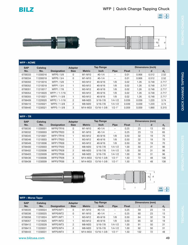
49www.bilzusa.com
TE
CH
NIC
AL
SP
EC
IALT
Y P
RO
DU
CT
SQ
UIC
K C
HA
NG
E T
AP
PIN
GS
YN
CH
RO
CH
UC
KS
WFP – Morse Taper
SAP No.
Catalog No. Designation
Adapter Size
Tap Range Dimensions (mm)
Metric Inch Pipe Float l d d2
6708335 11200024 WFP0/MT1 0 M1-M10 #0-1/4 – 0.25 59 23 13
6708336 11200025 WFP0/MT2 0 M1-M10 #0-1/4 – 0.25 60 23 13
6708356 11210024 WFP1/MT1 1 M3-M12 #0-9/16 1/8 0.50 64 32 19
6708357 11210025 WFP1/MT2 1 M3-M12 #0-9/16 1/8 0.50 65 32 19
6708412 11220028 WFP2/MT3 2 M8-M20 5/16-7/8 1/4-1/2 1.00 91 50 31
6708413 11220031 WFP2/MT4 2 M8-M20 5/16-7/8 1/4-1/2 1.00 92 50 31
6708443 11230031 WFP3/MT4 3 M14-M33 13/16-1-3/8 1/2-1" 1.50 132 72 48
d2 d
l DIN228B
WFP | Quick Change Tapping Chuck
WFP – ACME
SAP No.
Catalog No. Designation
Adapter Size
Tap Range Dimensions (inch)
Metric Inch Pipe Float l d d2
6708333 11200016 WFP0/5/8 0 M1-M10 #0-1/4 – 0.01 0.906 0.512 2.52
6708334 11200018 WFP0/3/4 0 M1-M10 #0-1/4 – 0.01 0.906 0.512 2.52
6708350 11210016 WFP1/5/8 1 M3-M12 #0-9/16 1/8 0.02 1.26 0.748 2.717
6708352 11210018 WFP1/3/4 1 M3-M12 #0-9/16 1/8 0.02 1.26 0.748 2.717
6708351 11210017 WFP1/7/8 1 M3-M12 #0-9/16 1/8 0.02 1.26 0.748 2.717
6708354 11210020 WFP1/1-1/16 1 M3-M12 #0-9/16 1/8 0.02 1.26 0.748 2.717
6708355 11210021 WFP1/1-3/8 1 M3-M12 #0-9/16 1/8 0.02 1.26 0.748 2.717
6708409 11220020 WFP2/1-1/16 2 M8-M20 5/16-7/8 1/4-1/2 0.039 0.039 1.220 3.74
6708410 11220021 WFP2/1-3/8 2 M8-M20 5/16-7/8 1/4-1/2 0.039 0.039 1.220 3.74
6708440 11230021 WFP3/1-3/8 3 M14-M33 13/16-1-3/8 1/2-1" 0.059 0.059 1.890 5.315
WFP – TR
SAP No.
Catalog No. Designation
Adapter Size
Tap Range Dimensions (mm)
Metric Inch Pipe Float l d d2
6708330 11200001 WFP0/TR16 0 M1-M10 #0-1/4 – 0.25 23 13 65
6708332 11200003 WFP0/TR20 0 M1-M10 #0-1/4 – 0.25 23 13 65
6708345 11210001 WFP1/TR16 1 M3-M12 #0-9/16 1/8 0.50 32 19 70
6708346 11210003 WFP1/TR20 1 M3-M12 #0-9/16 1/8 0.50 32 19 70
6708349 11210006 WFP1/TR28 1 M3-M12 #0-9/16 1/8 0.50 32 19 70
6708400 11220003 WFP2/TR20 2 M8-M20 5/16-7/8 1/4-1/2 1.00 50 31 96
6708402 11220006 WFP2/TR28 2 M8-M20 5/16-7/8 1/4-1/2 1.00 50 31 96
6708403 11220009 WFP2/TR36 2 M8-M20 5/16-7/8 1/4-1/2 1.00 50 31 96
6708436 11230006 WFP3/TR28 3 M14-M33 13/16-1-3/8 1/2-1" 1.50 72 48 136
6708438 11230009 WFP3/TR36 3 M14-M33 13/16-1-3/8 1/2-1" 1.50 72 48 138
DIN6327
l
dd2

50 www.bilzusa.com
SY
NC
HR
O C
HU
CK
SQ
UIC
K C
HA
NG
E TA
PP
ING
SP
EC
IALT
Y P
RO
DU
CT
ST
EC
HN
ICA
L
ASBA | Over Spindle Adapter
ASBA – Inch
SAP No.
Catalog No. Designation Nut Size
Dimensions (inch)
d1
adj. adaptors d d3 g (UNF) l l1 l2
6724485 33001010 ASBA.500" SSM.500" 0.500 1/2"-16 0.945 0.735 1/4-28 1.25 2.46 0.354
6724501 33003002 ASBA.625" SSM.625" 0.625 5/8"-16 1.181 0.985 5/16-24 1.25 2.58 0.374
6724502 33003003 ASBA.750" SSM.750" 0.750 3/4"-12 1.496 1.235 5/16-24 1.25 2.72 0.433
6724503 33003004 ASBA.875" SSM.875" 0.875 7/8"-12 1.654 1.360 5/16-24 1.56 3.19 0.472
6724514 33005010 ASBA1.000" SSM1.000" 1.000 1"-12 1.811 1.484 5/16-24 1.56 3.23 0.472
6724504 33003006 ASBA1.063" SSM1.063" 1.063 1-1/16"-12 1.929 1.510 5/16-24 1.56 3.27 0.472
6724505 33003007 ASBA1.375" SSM1.375" 1.375 1-3/8"-12 2.362 1.985 5/16-24 1.81 3.94 0.630
ASBA – Metric
SAP No.
Catalog No. Designation Nut Size
Dimensions (mm)
d1
Screw No. d d3 g l l1 l2
6724515 33012010 ASBA12 SSM12 12 BN138-62 24 20 M5 22 52 9
6724523 33016010 ASBA16 SSM16 16 BN138-25 30 25 M6 34 67 9.5
6724540 33020010 ASBA20 SSM20 20 BN138-25 38 32 M6 34 72 11
6724561 33025010 ASBA25 SSM25 25 BN138-4 45 37 M8 38 79 12
6724573 33028010 ASBA28 SSM28 28 BN138-4 48 40 M8 38 81 12
6724605 33036010 ASBA36 SSM36 36 BN138-5 60 50 M8 45 100 16
g
l±0,2 l2+0,02
d1 d-0,2
l1Spindle head
d3f7
SSM | Quick Change Adjusting Nut
SSM – Inch
SAP No.
Catalog No. Designation
Dimensions (inch)
ACME d d2 l2 l36724493 33002001 SSM.500" 1/2"-16 0.846 0.645 0.354 0.354
6724494 33002002 SSM.625" 5/8"-16 1.023 0.783 0.374 0.354
6724495 33002003 SSM.750" 3/4"-12 1.299 1.000 0.433 0.354
6724496 33002004 SSM.875" 7/8"-12 1.456 1.137 0.472 0.393
6724497 33002005 SSM1.000" 1"-12 1.574 1.256 0.472 0.393
6724498 33002006 SSM1.063" 1-1/16"-12 1.653 1.334 0.473 0.393
6724499 33002007 SSM1.375" 1-3/8"-12 2.126 1.708 0.629 0.393
6724500 33002008 SSM1.875" 1-7/8"-12 2.824 2.279 0.787 0.551
d2 d
l2
l3Contacting chuck

51www.bilzusa.com
TE
CH
NIC
AL
SP
EC
IALT
Y P
RO
DU
CT
SQ
UIC
K C
HA
NG
E T
AP
PIN
GS
YN
CH
RO
CH
UC
KS
ASBVA | Over Spindle Adapter
ASBVA – Inch
SAP No.
Catalog No. Designation Nut Size
Dimensions (inch)
d1 Screw No. d d3 g (UNF) l l1 l26724506 33004002 ASBVA.625" SSM.625" 0.625 BN138-65 1.102 0.985 Nr10-32 0.315 1.181 0.394
6724507 33004003 ASBVA.750" SSM.750" 0.750 BN138-65 1.338 1.235 Nr10-32 0.315 1.181 0.433
6724508 33004004 ASBVA.875" SSM.875" 0.875 BN138-65 1.535 1.360 Nr10-32 0.315 1.260 0.472
6724510 33004006 ASBVA1.062" SSM1.062" 1.062 BN138-30 1.732 1.610 1/4-28 0.315 1.260 0.472
6724511 33004007 ASBVA1.375" SSM1.375" 1.375 BN138-31 2.244 1.985 1/4-28 0.354 1.535 0.630
ASBVA – Metric
SAP No.
Catalog No. Designation Nut Size
Dimensions (mm)
d1 Screw No. d d3 g (UNF) l l1 l26724533 33016051 ASBVA16 SSM16 16 BN138-11 27 25 M5 8 30 9.5
6724553 33020051 ASBVA20 SSM20 20 BN138-11 34 32 M5 8 30 11
6724568 33025051 ASBVA25 SSM25 25 BN138-2 41 37 M6 8 32 12
6724587 33028051 ASBVA28 SSM28 28 BN138-25 44 40 M6 8 32 12
6724602 33032051 ASBVA32 SSM32 32 BN138-2 49 45 M6 9 39 13.5
6724618 33036051 ASBVA36 SSM36 36 BN138-2 55 50 M6 9 39 16
6724632 33048051 ASBVA48 SSM48 48 BN138-5 73 67 M8 11 51 20
l2 + 0,02
d-0,02
l ± 0,2
g
d 3
l130°
Spindle head
d1 d4 g6
BN
d2 d
l2
l3Contacting chuck
SSM | Quick Change Adjusting Nut
SSM – Metric
SAP No.
Catalog No. Designation
Dimensions (mm)
TR d d2 l2 l36805012 33012020 SSM12 12 22 16.4 9.0 9
6805016 33016020 SSM16 16 26 19.9 9.5 9
6805020 33020020 SSM20 20 33 25.4 11.0 9
6805025 33025020 SSM25 25 40 31.9 12.0 10
6805028 33028020 SSM28 28 42 33.9 12.0 10
6805032 33032020 SSM32 32 47 37.9 13.5 10
6805036 33036020 SSM36 36 54 43.4 16.0 10
6805048 33048020 SSM48 48 72 57.9 20.0 14

52 www.bilzusa.com
SY
NC
HR
O C
HU
CK
SQ
UIC
K C
HA
NG
E TA
PP
ING
SP
EC
IALT
Y P
RO
DU
CT
ST
EC
HN
ICA
L
SBK | Quick Change System
SBK – Morse Taper Shank
SAP No.
Catalog No. Designation
Dimensions (inch)
Size d l26723619 30120002 SBK2/MT2 2 1.968 2.952
6723620 30120003 SBK2/MT3 2 1.968 2.952
6723648 30130003 SBK3/MT3 3 2.362 3.464
6723649 30130004 SBK3/MT4 3 2.362 3.503
6723668 30140004 SBK4/MT4 4 2.834 4.015
6723669 30140005 SBK4/MT5 4 2.834 4.015
d
l
APPLICATION: For drilling, counterboring, chamfering, reaming and tapping operations on drilling radial drilling machines and NC machines.
FEATURES: Quick change system with automatic locking of the adaptor in the chuck. Tool changes can be made with rotating spindle. Minimum movement when changing tools. High concentricity of the adaptor in the chuck is achieved by the axially and radially free-of-play location of the adaptor taper. Can be applied vertically and horizontally. For right and left hand rotation.
SELK | Quick Change Adaptor
SELK – Tap Chuck
SAP No.
Catalog No. Designation
Dimensions (inch)
Adap. Size Tap Range Chuck Size Tension Compression d l26723643 30125001 SELK2/1 1 #0-9/16" 2 0.295 0.295 1.417 1.653
6723644 30125002 SELK2/2 2 5/16"-7/8" 2 0.492 0.492 2.086 2.834
6723662 30135002 SELK3/2 2 5/16"-7/8" 3 0.492 0.492 2.086 2.598
6723663 30135003 SELK3/3 3 13/16"-1-3/8" 3 0.787 0.787 3.070 4.960
6723693 30145003 SELK4/3 3 13/16"-1-3/8" 3 0.787 0.787 3.070 4.763
6723694 30145004 SELK4/4 4 1"-1-7/8" 4 0.885 0.885 3.779 5.314
l2
d1

53www.bilzusa.com
TE
CH
NIC
AL
SP
EC
IALT
Y P
RO
DU
CT
SQ
UIC
K C
HA
NG
E T
AP
PIN
GS
YN
CH
RO
CH
UC
KS
SEK | Quick Change Adaptor
SEK – ER
SAP No.
Catalog No. Designation
Dimensions (mm)
ER Size ER Range l2 (min/max) d d2 l6723783 30190204 SEK2/ESX16 ER16 1mm-10mm 21/43 32 42 40
6723640 30121053 SEK2/ESX20 ER20 1mm-13mm 22/47 34 42 46
6723744 30190140 SEK3/ESX25 ER25 2mm-16mm 24/51 42 50 52
6723790 30190215 SEK3/ESX32 ER32 3mm-20mm 29/56 50 50 53
6723780 30190196 SEK3/ESX40 ER 40 4mm-26mm 35/62 63 60 73
6723686 30141053 SEK4/ESX40 ER 40 4mm-26mm 35/62 63 60 70
SEK – Morse Tap Adapter
SAP No.
Catalog No. Designation
Dimensions (inch)
Size d1 l26723630 30121001 SEK2/MT1 2 1.653 0.708
6723631 30121002 SEK2/MT2 2 1.653 1.200
6723653 30131001 SEK3/MT1 3 1.968 0.807
6723654 30131002 SEK3/MT2 3 1.968 0.807
6723655 30131003 SEK3/MT3 3 1.968 1.515
6723675 30141002 SEK4/MT2 4 2.362 1.318
6723676 30141003 SEK4/MT3 4 2.362 1.318
6723677 30141004 SEK4/MT4 4 2.362 2.834
SEK – B
SAP No.
Catalog No. Designation
Dimensions (inch)
Size d1
6723632 30121012 SEK2/B12 2 1.653
6723633 30121015 SEK2/B16 2 1.653
6723657 30131016 SEK3/B16 3 1.968
6723680 30141016 SEK4/B16 4 2.362
d1
l1
l2
l 2
d1
l2
d1B

54 www.bilzusa.com
SY
NC
HR
O C
HU
CK
SQ
UIC
K C
HA
NG
E TA
PP
ING
SP
EC
IALT
Y P
RO
DU
CT
ST
EC
HN
ICA
L
This self reversing tapping attachment is designed for use on drilling machines which have only manual feed facilities and which do not have a reversible spindle.
The tool design is simple, effective, and is virtually mainte-nance free. The unit is fitted into the machine spindle by virtue of its morse taper shank, with the stop arm located against the column of the drilling machine to ensure effective and positive action. The design of the units is such that it can be used for either right or left handed tapping operations.
The unit automatically changes direction when the manual feed is reversed.
The unit accepts both Bilz WE and WES tap adaptors.
The use of WES tap adaptors prevents tap breakage in bottoming hole tapping applications.
Application:The tapping attachment is designed for use on vertical drilling machines.
Operation:Before operation, the stop arm should be located in the tapped hole on the main body of the tapping attachment and screwed into position. The other end of the stop arm should then be in contact with either the main pillar of the drilling machine or an appropriate stop device mounted on the machine, the purpose of this is to prevent the tapping attachment from rotating. On the way out use approximately double feed rate.
Maintenance: The tapping attachment is maintenance free.
Safety Precautions:The stop arm must not be held in the hand and a safe distance between the operator and the machine should be greater than the length of the stop arm.•Max.RPMforTA12is1200perminute•Max.RPMforTA20is500perminute•ThetappingrangeforTA12isM3-M12•ThetappingrangeforTA20isM8-M20.•Quickchangeadaptorswithsafetyclutchmustbeused
when tapping blind holes.
Risk of injury to the operator if the above precautions are not followed!
TA | Tapping Attachment | Quick Change System

55www.bilzusa.com
TE
CH
NIC
AL
SP
EC
IALT
Y P
RO
DU
CT
SQ
UIC
K C
HA
NG
E T
AP
PIN
GS
YN
CH
RO
CH
UC
KS
TA | Tapping Attachment | Quick Change System
Shanks
SAP No. Designation
02002700 MT-2SHANK7/8-20
02002800 MT-3SHANK7/8-20
02002900 MT-4SHANK7/8-20
02003200 1/2"DIASHANK7/8-20
02003300 5/8"DIASHANK7/8-20
02003400 3/4"DIASHANK7/8-20
02003500 7/8"DIASHANK7/8-20
02005500 R-8SHANK7/8-20
02006100 1"DIASHANK7/8-20
02012000 NMTB30SHANK7/8-20
02012100 NMTB40SHANK7/8-20
TA / MK-WF – Inch
SAP No. Designation
Max RPM
Dimensions (inch/mm)
b l l1 d d1 d2– + i
6802342 TA127/8-20-WF1 1#4-1/2" M3-M12
1200.236
6 mm4.724
120mm2.362
60 mm3.15080mm
1.26032mm
.74819mm
0 12.5 1.73
6802343 TA207/8-20-WF2 25/16-3/4" M8-M20
500.3158mm
5.905150mm
3.38686mm
3.937100mm
1.96950mm
1.22031mm
0 16.5 1.88
i = gear ratio for return cycle
d2 d
l
d1
bl1
Self feed
Stop arm
DIN228B – +

56 www.bilzusa.com
SY
NC
HR
O C
HU
CK
SQ
UIC
K C
HA
NG
E TA
PP
ING
SP
EC
IALT
Y P
RO
DU
CT
ST
EC
HN
ICA
L
DSPL | Tapping Chuck
DSPL-MT – Inch
SAP No. Designation
Dimensions (inch)
Keysl l1 Metric Taps Pipe Float
Length Comp.
d d1Comp. Tens.10121202 DSPL12/MT2
5.314
0.708-0x.787 M3-M12 #6-1/2 1/8 0.039 0.393 0.787 2.283 2.086 DSPLK1210121203 DSPL12/MT3
10600057 DSPL12/SS3/45.125
10600043 DSPL12/SS1
10201203 DSPL20/MT3 6.692
0.905-1.102 M8-M20 1/8-3/4 1/8-1/4 0.058 0.393 0.787 3.267 2.992 DSPLK2010201204 DSPL20/MT4 6.732
10600070 DSPL20/SS16.417
10600024 DSPL20/SS1-1/4
10301204 DSPL30/MT49.133
0.984-1.338 M14-M30 5/8-1-1/8 1/4-1/2 0.078 0.393 1.181 4.173 4.173 DSPLK3010301205 DSPL30/MT5
10600025 DSPL30/SS1-1/4 8.740
10421205 DSPL42/MT5 10.590
1.614-1.889 M18-M42 3/4-1-5/8 1/2-1" 0.078 0.393 1.181 4.921 4.724 DSPLK4010421006 DSPL42/MT6 10.668
10600026 DSPL42/SS1-1/2 10.245
d1
l
l1K
M12
M10
M 8
d 2Ød
DIN228B – +

57www.bilzusa.com
TE
CH
NIC
AL
SP
EC
IALT
Y P
RO
DU
CT
SQ
UIC
K C
HA
NG
E T
AP
PIN
GS
YN
CH
RO
CH
UC
KS
High Performance Tapping Attachments with Integrated Reversing Gear
BILZtappingattachmentsareofmodulardesignand can therefore meet the specific requirements of individual machines. They can be used on machining centres with automatic tool changers and on special purpose machines.
Because of the integrated maintenance free reversing gear, changes in direction of the machine spindle are unnecessary.
The length compensation on extension, with a ball release system which operates when in reverse, guaranteesthreaddepthsof60.15mmuptoaspeedof 4000 rpm. The GNCK tapping unit with coolant feed, canfacilitatepressuresuptoamaximumof50 bar.
Precision collets ensure that the tap is securely clamped, and additional square drivers can be utilised where high torque is being generated, for example, when thread forming.
The torque support locks the unit relative to the spindle, thus making automatic tool changing possible. When tool changing takes place, the locking mechanism releases the torque support and allows the tool changing operation to be effected.
Because of the use of the reversing gears, high tapping speeds are possible resulting in significantly shorter cycle times compared to conventional tapping.
Extended spindle lengths upon on request.
GNCN-GNCK Tapping Attachment
Designation Ø dnmaxrpm
Pmaxbar B E d1 d2 h l l1 l2 l3
GNC6-MMS ESX12 M3-M6 3-7 4000 10 4 6 19 70 27 – – 106 13/21
GNC12-MMS ESX16 M4-M12 3-10 2500 10 5 9 28 87 37 – – 119 25/45
GNC20-MMS ESX25 M12-M20 7.1-16 1500 10 8 10 42 100 45 187 175 142 29/42
GNCN6C-ESX12/ ESX12 M3-M6 3-7 4000 – 3.5 6.5 19 70 27 132 125 106 13/21
GNCK6C-ESX12/ ESX12 M3-M6 3-7 4000 50 3.5 6.5 19 70 27 132 125 106 13/21
GNCN12C-ESX16/ ESX16 M4-M12 3-10 2500 – 5 9 28 87 37 153 143 119 25/45
GNCK12C-ESX16/ ESX16 M4-M12 3-10 2500 50 5 9 28 87 37 153 143 119 25/45
GNCN20C-ESX25/ ESX25 M12-M20 7.1-16 1500 – 8 10 42 100 45 187 175 142 29/42
GNCK20C-ESX25/ ESX25 M12-M20 7.1-16 1500 50 8 10 42 100 45 187 175 142 29/42
Weights For inquiries please add:
UnitGNCN/GNCK 6 C approx.1.75KGSGNCN/GNCK 12 C approx.3.10KGSGNCN/GNCK 20 C approx.5.15KGSTorque SupportDependingondesignapprox.0.5–1.0KGSShankDependingondesignapprox.0.8–3.0KGS
– machine manufacturer – machine type – serial number machine – spindle location/size – with/without coolant – thread sizeAttention! The tap must be suitable for the material and the process. Please respect the recommended speed of the tap manufacturers!
Specific machine no. Please state the exact machine model Collet ESX16-8;Driver BN1716-5;Set contents: wrench, allen key

58 www.bilzusa.com
SY
NC
HR
O C
HU
CK
SQ
UIC
K C
HA
NG
E TA
PP
ING
SP
EC
IALT
Y P
RO
DU
CT
ST
EC
HN
ICA
L
GNCN-GNCK Tapping Attachment
d2 l2
l1
l
l3
Ø d
Ø d
1
51-8
0*
h
ESX...
35
max.48
B E
Length compensation on extension
Self feed
Driver
Torque support
Toolholder
Spindle End
position
End position
Programming Example
At the starting position with a selected safety margin YB the followingequationsgive: ZV = YB+Z–0.5B ZR=Z+E+0.5B+1For tapping operations on machining centres using GNCN/GNCK, the following should be taken into account when programming the machine:• Nochangeindirectionofrotationofthemachinespindle,
as this is carried out by the GNCN/GNCK• Feed=95–98%ofthreadpitch• Nodwellingtime• Varyingcuttinggeometryofthetap• Selfspeed• Compensationonextensionafterrelease
Z =TappingdepthZV = Spindle advanceZR = Spindle returnY(A, B) = Safety marginB = Self feedE = Compensation on extension
*>80availableasspecialdesign.Attachmentswith50mmand100mmextendedspindleavailableasspecialdesign

59www.bilzusa.com
TE
CH
NIC
AL
SP
EC
IALT
Y P
RO
DU
CT
SQ
UIC
K C
HA
NG
E T
AP
PIN
GS
YN
CH
RO
CH
UC
KS
GNCN-GNCK Tapping Attachment
Designation Driver Square l3
SetGNC6-MMS I – 2.7-5 13-21 I GNCK-ESX12GNCN6C-ESX12 SAP No. SAP No. 69831955GNCK6C-ESX12 I I
SAP No. SAP No.I I
SAP No. SAP No.GNC12-MMS I BN1716-4 4 27 I GNCK-ESX16GNCN12C-ESX16 SAP No. 6930574 SAP No. 6831954GNCK12C-ESX16 I BN1716-4.5 4.5 28 I
SAP No. 6930575 SAP No.I BN1716-5 4.9-5 29 I
SAP No. 6930576 SAP No.I BN1716-5.6 5.5-5.6 29 I
SAP No. 6930577 SAP No.I BN1716-6.3 6.2-6.3 30 I
SAP No. 6930578 SAP No.I BN1716-6.5 6.5 30 I
SAP No. 6930579 SAP No.I BN1716-6.8 6.8 31 I
SAP No. 6930581 SAP No.I – 8 44 I
SAP No. – SAP No.GNC20-MMS I – <5 29 I GNCK-ESX25GNCN20C-ESX25 SAP No. SAP No. 6831956GNCK20C-ESX25 I BN1725-5.6 5-5.6 35
SAP No. 6943252 SAP No.I BN1725-6.5 6.2-6.5 36
SAP No. 6943253 SAP No.I BN1725-7.1 7.1 38 I
SAP No. 6941587 SAP No.I BN1725-8 7-8 38 I
SAP No. 6931467 SAP No.I BN1725-9 8-9 40 I
SAP No. 6943834 SAP No.I BN1725-10 9-10 40 I
SAP No. 6931468 SAP No.I BN1725-11.2 11.2 42 I
SAP No. 6943835 SAP No.I BN1725-12 11-12 42 I
SAP No. 6931469 SAP No.

60 www.bilzusa.com
SY
NC
HR
O C
HU
CK
SQ
UIC
K C
HA
NG
E TA
PP
ING
AD
VAN
CE
D S
OLU
TIO
NS
TE
CH
NIC
AL
ADVANCED SOLUTIONS
V I E WT H EW E B S I T E
Tools designed to expand machining capabilities on CNC
machining centers. Do more in a single setup with these
“advanced application tools”.
60 www.bilzusa.com

61www.bilzusa.com
TE
CH
NIC
AL
AD
VAN
CE
D S
OLU
TIO
NS
QU
ICK
CH
AN
GE
TA
PP
ING
SY
NC
HR
O C
HU
CK
S
PN-GPK Floating Holders | Advanced Solutions
Bilz Floating Holders—Highest Quality for Perfect Finish and Accuracy
Highest possible drilling quality with perfect accuracy on reaming operations can only be achieved when the clamping system does not cause any radial force on the cutting tool. The requirement regarding the tolerance zone, the surface roughness and the roundness presupposes a clamping system which compensates all inaccuracy of position occurring. In addition, the system should be without circumferential backlash. Damage to the edges of the tool is thus avoided. This is guaranteed with Bilz floating holders.

62 www.bilzusa.com
SY
NC
HR
O C
HU
CK
SQ
UIC
K C
HA
NG
E TA
PP
ING
AD
VAN
CE
D S
OLU
TIO
NS
TE
CH
NIC
AL
formbore System Tools | Advanced Solutions
For the first time you can produce a high variety of inner and outer profiles with the highest possible precision by means of simple drilling and turning processes on normal machining centres.
formbore system tools can be used on:
• millingmachines • machiningcentres • turningmachines • specialmachines
formbore system tools work independently of the machining spindle. It is not necessary to calculate and programme the synchronous coordination to the machine spindle. formbore system tools are designed for different profiles and profile sizes.
The formbore system tool can replace expensive processes such as reaming, erosion or milling. Further advantages are blind holes without residual chips and the constant accuracy due to the correction of the cutter wear. The torque support and the modular tool holders are identical to the ones used on the Bilz GNCK/GNCN tapping attachments.
Design and Mode of Operation of the formbore System Tools
formbore system tools consist of two components: cam drive and bore head. The rotating drive shaft is located in the case. The torque driven control determines the movement sequence of the bore head. The deflection of the boring bar is entirely controlled by rolling elements. formbore system tools therefore operate practically wear- and maintenance-free and make machining of most materials up to 900N/mm2 strength possible. For inside processing, a formbore is initially machined up to a maximum of 0.5 mmdiametersmallerthanthesmallestIDoftheshape. The actual form bore operation is carried out in a single process with profile adjusted speed and feed appropriate to the material being machined.
The formbore system tool is a system for a practical versatility, flexibility and time and cost saving in daily work.Letusknowyourprocessingrequirements.Youwill receive our specific tool recommendation and our offer will convince you of the advantages of the formbore system tooling.

63www.bilzusa.com
TE
CH
NIC
AL
AD
VAN
CE
D S
OLU
TIO
NS
QU
ICK
CH
AN
GE
TA
PP
ING
SY
NC
HR
O C
HU
CK
S
formbore System Tools | Advanced Solutions
formbore System Tools for Machining Centers, Milling and Drilling Machines
5
x
x
D
A
L
B
A
L
Description A mm nmax rpm Ø D mm Profile (spanner size) mmFBT1/... ≥51 1000 80 square:SQ4–14 hexagon:SQ4–21
FBT2/... ≥51 500 125 square:SQ4–22 hexagon:SQ4–38
order example:
FBT 2 / 29 . 22
22 =TypeMCH–300
29 =MachineManufacturerHeller
2 =formbore Size2
FBT = formbore Tool
formbore System Tools for Turning Machines
5
x
x
D
A
L
B
A
L
Description nmax rpm Profile (spanner size) mmFBT1/... 1000 square:SQ4–14 hexagon:SQ4–21
FBT2/... 500 square:SQ4–22 hexagon:SQ4–38
order example:
FBT 2 / 100 . 1
1 =TypeG200/V160
100 =MachineManufacturerIndex
2 =formboreSize2
FBT = formbore Tool

64 www.bilzusa.com
SY
NC
HR
O C
HU
CK
SQ
UIC
K C
HA
NG
E TA
PP
ING
AD
VAN
CE
D S
OLU
TIO
NS
TE
CH
NIC
AL
formbore System Tools | Advanced Solutions
formbore Cam Blocks
The following profiles can be produced:
Folgende Profile können hergestellt werden:The following profiles can be produced:
Bestellbeispiel:order example:
Weitere Profile auf AnfrageFurther profiles on request
Hinweis:Bitte bei Anfrage und Bestellung immer eine Zeich-nung der herzustellenden Kontur mitsenden,um die genaue Abmessung des Kurvenblockes zudefinieren. Die nachfolgenden formbore-Ausbohr-und formbore-Überdrehstähle sind auf die Konturdes Kurvenblockes ausgelegt.
7
FBK 1 04 – 0810 / 1
1 = Variante variant 1 (z.B. Eckenradius e.g. corner radius)0810 = Abmessung Vierkant= 8,10 mm measurement square= 8,10 mm04 = Vierkant square1 = Kurvenblock für formbore-Systemwerkzeug der Größe 1
= cam block for formbore system tool Size 1FBT = FormBoreKurvenblock formbore cam block
Profile Vierkant Sechskant Achtkant Fläche am Zylinder Schlüsselweite Polygon als Vorbearbeitungprofiles square hexagon octagon area at the cylinder spanner size polygon as pre-processing
Verschlüsselung04 06 08 01 02 21code
Note:Please include a drawing of the contour with all enquiriesand orders in order to define the exact measurements ofthe cam block. The following formbore bore out steels andformbore over turning steels are designed for the contourof the cam block.
order example:
FBK 1 04 – 0810 / 1
1 =Variant1(e.g.cornerradius)
0810 =Measurementsquare=8.10mm
04 = Square
1 =Camblockforformbore system toolSize1
FBT = formbore Tool
NOTE: Please include a drawing of the contour with all inquiries and orders in order to define the exact measurements of the cam block. The following formbore boring bars and formbore external turning bars are designed for the contour of the cam block.
Profiles Square Hexagon OctagonArea at the
CylinderSpanner
SizePolygon as
Pre-Processingcode 04 06 08 01 02 21
formbore Accessories for Internal Shapes
Bore out steel
Ausbohrstählebore out steel
Identifikation der formbore-Ausbohrstähleidentification of the formbore bore out steel
Die Ausbohrstähle sind auf die Geometrie des jeweiligen Kurvenblockes abgestimmt.The bore out steels are coordinated with the geometry of the respective cam block.
Schneidenträgerinsert holder
Bezeichnungdescription
ASI–26.00–07ASI–31.00–07ASI–38.00–07
Bohrstangeboring bar
Bezeichnungdescription
ASI–26/00–ABS40–44ASI–31/38–ABS40–44
ASI 12 0700 / X
X = Variante variant X (z.B. Bohrtiefe e.g. bore depth)0700 = theoretischer Bohrdurchmesser theoretical bore diameter12 = Schaftdurchmesser Ausbohrstahl shank diameter bore out steelASI = AusbohrStahl Innen bore out steel internal
Identification of the formbore boring bar
ASI 12 0700 / X
X =VariantX(e.g.boredepth)
0700=theoreticalborediameter
12 =Shankdiameterboreoutsteel
ASI = Bore out steel internal
The bore out steels are coordinated with the geometry of the respective cam block.
Insert Holder
Ausbohrstählebore out steel
Identifikation der formbore-Ausbohrstähleidentification of the formbore bore out steel
Die Ausbohrstähle sind auf die Geometrie des jeweiligen Kurvenblockes abgestimmt.The bore out steels are coordinated with the geometry of the respective cam block.
Schneidenträgerinsert holder
Bezeichnungdescription
ASI–26.00–07ASI–31.00–07ASI–38.00–07
Bohrstangeboring bar
Bezeichnungdescription
ASI–26/00–ABS40–44ASI–31/38–ABS40–44
ASI 12 0700 / X
X = Variante variant X (z.B. Bohrtiefe e.g. bore depth)0700 = theoretischer Bohrdurchmesser theoretical bore diameter12 = Schaftdurchmesser Ausbohrstahl shank diameter bore out steelASI = AusbohrStahl Innen bore out steel internal
DescriptionASI–26.00–07
ASI–31.00–07
ASI–38.00–07
Boring Bar
Ausbohrstählebore out steel
Identifikation der formbore-Ausbohrstähleidentification of the formbore bore out steel
Die Ausbohrstähle sind auf die Geometrie des jeweiligen Kurvenblockes abgestimmt.The bore out steels are coordinated with the geometry of the respective cam block.
Schneidenträgerinsert holder
Bezeichnungdescription
ASI–26.00–07ASI–31.00–07ASI–38.00–07
Bohrstangeboring bar
Bezeichnungdescription
ASI–26/00–ABS40–44ASI–31/38–ABS40–44
ASI 12 0700 / X
X = Variante variant X (z.B. Bohrtiefe e.g. bore depth)0700 = theoretischer Bohrdurchmesser theoretical bore diameter12 = Schaftdurchmesser Ausbohrstahl shank diameter bore out steelASI = AusbohrStahl Innen bore out steel internal
DescriptionASI–26/00–ABS40–44
ASI–31/38–ABS40–44

65www.bilzusa.com
TE
CH
NIC
AL
AD
VAN
CE
D S
OLU
TIO
NS
QU
ICK
CH
AN
GE
TA
PP
ING
SY
NC
HR
O C
HU
CK
S
formbore System Tools | Advanced Solutions
formbore Accessories for External Shapes
Over turning steel:
ASA 12 0700 / 1
1 = Variante variant 1 (z.B. Bohrtiefe e.g. bore depth)0700 = theoretischer Bohrdurchmesser theoretical bore diameter12 = Schaftdurchmesser Überdrehstahl shank diameter over turning steelASA = AusbohrStahlAussen over turning steel external
Überdrehstähleover turning steel
Identifikation der formbore-Überdrehstähleidentification of the formbore over turning steel
Die Überdrehstähle sind auf die Geometrie des jeweiligen Kurvenblockes abgestimmt.The bore out steels are coordinated with the geometry of the respective cam block.
Schneidenträgerinsert holder
Bezeichnungdescription
ASA–26.00–07ASA–31.00–07ASA–38.00–07
Bohrstangeboring bar
Bezeichnungdescription
ASA–26/00–ABS40–44ASA–31/38–ABS40–44
Identification of the formbore over turning steel
ASI 12 0700 / 1
1 =Variant1(e.g.boredepth)
0700=theoreticalborediameter
12 =Shankdiameteroverturningsteel
ASI = over turning steel external
The bore out steels are coordinated with the geometry of the respective cam block.
Insert Holder
Ausbohrstählebore out steel
Identifikation der formbore-Ausbohrstähleidentification of the formbore bore out steel
Die Ausbohrstähle sind auf die Geometrie des jeweiligen Kurvenblockes abgestimmt.The bore out steels are coordinated with the geometry of the respective cam block.
Schneidenträgerinsert holder
Bezeichnungdescription
ASI–26.00–07ASI–31.00–07ASI–38.00–07
Bohrstangeboring bar
Bezeichnungdescription
ASI–26/00–ABS40–44ASI–31/38–ABS40–44
ASI 12 0700 / X
X = Variante variant X (z.B. Bohrtiefe e.g. bore depth)0700 = theoretischer Bohrdurchmesser theoretical bore diameter12 = Schaftdurchmesser Ausbohrstahl shank diameter bore out steelASI = AusbohrStahl Innen bore out steel internal
DescriptionASI–26.00–07
ASI–31.00–07
ASI–38.00–07
Boring Bar
Ausbohrstählebore out steel
Identifikation der formbore-Ausbohrstähleidentification of the formbore bore out steel
Die Ausbohrstähle sind auf die Geometrie des jeweiligen Kurvenblockes abgestimmt.The bore out steels are coordinated with the geometry of the respective cam block.
Schneidenträgerinsert holder
Bezeichnungdescription
ASI–26.00–07ASI–31.00–07ASI–38.00–07
Bohrstangeboring bar
Bezeichnungdescription
ASI–26/00–ABS40–44ASI–31/38–ABS40–44
ASI 12 0700 / X
X = Variante variant X (z.B. Bohrtiefe e.g. bore depth)0700 = theoretischer Bohrdurchmesser theoretical bore diameter12 = Schaftdurchmesser Ausbohrstahl shank diameter bore out steelASI = AusbohrStahl Innen bore out steel internal
DescriptionASI–26/00–ABS40–44
ASI–31/38–ABS40–44

66 www.bilzusa.com
SY
NC
HR
O C
HU
CK
SQ
UIC
K C
HA
NG
E TA
PP
ING
AD
VAN
CE
D S
OLU
TIO
NS
TE
CH
NIC
AL
formbore System Tools | Advanced Solutions
Female Square SQ 12 mm
Material Speed Feed MachineBrass 550rpm 0.04mm/1 Turning Machine
Hexagon SQ 22 mm
Material Speed Feed MachineBrass 400 rpm 0.06mm/1 Special Machine
Note: Interrupted Cut
Keyway SQ 8 mm, depth 20 mm
Material Speed Feed MachineSteel
900N/mm2 550rpm 0.03mm/1 Turning Machine
Note: Interrupted Cut
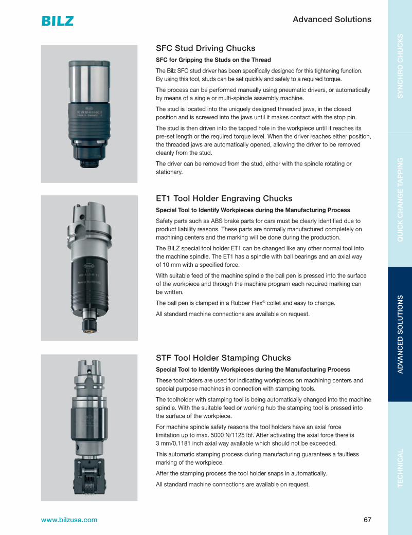
67www.bilzusa.com
TE
CH
NIC
AL
AD
VAN
CE
D S
OLU
TIO
NS
QU
ICK
CH
AN
GE
TA
PP
ING
SY
NC
HR
O C
HU
CK
S
Advanced Solutions
SFC Stud Driving ChucksSFC for Gripping the Studs on the Thread
The Bilz SFC stud driver has been specifically designed for this tightening function. By using this tool, studs can be set quickly and safely to a required torque.
The process can be performed manually using pneumatic drivers, or automatically by means of a single or multi-spindle assembly machine.
The stud is located into the uniquely designed threaded jaws, in the closed position and is screwed into the jaws until it makes contact with the stop pin.
The stud is then driven into the tapped hole in the workpiece until it reaches its pre-set length or the required torque level. When the driver reaches either position, the threaded jaws are automatically opened, allowing the driver to be removed cleanly from the stud.
The driver can be removed from the stud, either with the spindle rotating or stationary.
ET1 Tool Holder Engraving ChucksSpecial Tool to Identify Workpieces during the Manufacturing Process
Safety parts such as ABS brake parts for cars must be clearly identified due to product liability reasons. These parts are normally manufactured completely on machining centers and the marking will be done during the production.
TheBILZspecialtoolholderET1canbechangedlikeanyothernormaltoolintothemachinespindle.TheET1hasaspindlewithballbearingsandanaxialway of10mmwithaspecifiedforce.
With suitable feed of the machine spindle the ball pen is pressed into the surface of the workpiece and through the machine program each required marking can be written.
The ball pen is clamped in a Rubber Flex® collet and easy to change.
All standard machine connections are available on request.
STF Tool Holder Stamping ChucksSpecial Tool to Identify Workpieces during the Manufacturing Process
These toolholders are used for indicating workpieces on machining centers and special purpose machines in connection with stamping tools.
The toolholder with stamping tool is being automatically changed into the machine spindle. With the suitable feed or working hub the stamping tool is pressed into the surface of the workpiece.
For machine spindle safety reasons the tool holders have an axial force limitationuptomax.5000N/1125lbf.Afteractivatingtheaxialforcethereis 3mm/0.1181inchaxialwayavailablewhichshouldnotbeexceeded.
This automatic stamping process during manufacturing guarantees a faultless marking of the workpiece.
After the stamping process the tool holder snaps in automatically.
All standard machine connections are available on request.

68 www.bilzusa.com
SY
NC
HR
O C
HU
CK
SQ
UIC
K C
HA
NG
E TA
PP
ING
SP
EC
IALT
Y P
RO
DU
CT
ST
EC
HN
ICA
L
TECHNICAL
68 www.bilzusa.com
�www.lmt-bilz.com
Technische Informationen
Technical Information
F.46 www.lmt-tools.com
Anhang
Attachment
Toleranzen des Gewindeteils von Gewindebohrern;
Gewindebohrer für metrisches ISO-Gewinde
Tolerances on the threaded portion of taps;
taps for ISO metric threads
a—2
Muttergewinde Internal Thread
Toleranzlage H Position H of tolerance class
a
P
HH — 8
Au
= 0
B
asic
Pitc
h
Dia
met
erH — 8
TD
1— 2
D1 D
TD2
— 2D
2P
H — 8E
id — 2
Ei
— 2
a
H — 4
R
d2m
in
d2m
ax
d2 d dm
in
Es — 2TD2
— 2
Gewindebohrer Ta p
Toleranzfeld des Muttergewindes
Tolerance limits of the
Internal Thread
Toleranzfeld des Gewindebohrers
Tolerance limits of the tap
8H8H
7H
6H
5H
4H
8G
7G
6G
5G
4G
7G
6H
4H
6G
f = T
D2
(Qua
l. 5)
D2
Au
= 0
B
asic
Pitc
h D
iam
eter
D2
0,5t
0,3t
ALa
ge =
0,2
tªA
u
0,5t
0,3t
0,7t
0,1t
0,1t d
2T
D2
= 0
,2t
Muttergewinde
Toleranzlage H
Internal Thread
Tolerance H limits
Gewindebohrer
Toleranzlage
TapTolerance limits
Muttergewinde
Toleranzlage G
Internal Thread
Tolerance G limits
Technische Informationen
Technical Information
Technische InformationenTechnical Information
2Ø 2
0,5 x 45°
e1
e1
e2
20° ± 30
d9
0°- 35°

69www.bilzusa.com
TE
CH
NIC
AL
SP
EC
IALT
Y P
RO
DU
CT
SQ
UIC
K C
HA
NG
E T
AP
PIN
GS
YN
CH
RO
CH
UC
KS
Torque | Technical Information
Torque setting in
Nm MetricBSW
Whitworth
BSPWhitworth
Pipe
BSFWhitworth
fine
BSP taperWhitworth
Pipe tapered BA PG NPT taper UNC UNF
Torque setting in
ft/lbs0.3 M2 No.9 No.2 No.2 0.20.4 M2.5 No.8 No.3 0.30.5 M3 No.7 No.3 No.4 0.40.6 No.6 0.40.8 M3.5 1/8" No.5 No.4 No.5 0.61 No.4 No.5 No.6 0.71.2 M4 5/32" No.6 No.8 0.91.6 No.3 No.8 1.22 M5 No.2 No.10 1.52.5 3/16" No.12 1.83 3/16" No.1 No.10 1/4" 2.24 M6 7/32" 7/32" No.0 No.12 2.95 1/4" 1/4" 5/16" 3.66 G-1/8" 9/32" 1/4" 3/8" 4.38 M8 5/16" 5.810 5/16" 5/16" 7/16" 7.212 3/8" PG-7 1/2" 8.716 M10 3/8" 3/8" 1118 G-1/4" 7/16" 1/8" 9/16" 1320 PG-9 1/8" 5/8" 1422 M12 7/16" G-3/8" PG-11 7/16" 1525 1/2" PG-13.5 1828 PG-16 2032 9/16" 1/2" 3/4" 2336 M14 1/2" 2640 M16 9/16" 5/8" 9/16" 2845 11/16" PG-21 7/8" 3250 5/8" G-1/2" 1/4" 5/8" 3656 G-5/8" 1/4" 4063 M18 3/8" PG-29 4570 M20 3/4" G-3/4" 3/4" 3/8" 3/4" 1" 5080 M22 G-7/8" 13/16" PG-36 1-1/8" 5790 7/8" PG-42 1-1/4" 65100 7/8" PG-48 7/8" 1-3/8" 72110 1-1/2" 79125 M24 1" 90140 M27 1" G-1" 1" 101160 G-1-1/8" 1/2" 1/2" 115180 G-1-1/4" 1-1/8" 130200 G-1-3/8" 1-1/4" 3/4" 3/4" 1-1/8" 144220 M30 1-1/8" G-1-1/2" 159240 M33 1-1/4" G-1-3/4" 1-1/4" 173260 G-2" 1-3/8" 188280 M36 202300 G-2-1/4" 1-1/2" 216320 M39 1-5/8" 1-3/8" 231340 1-3/8" G-2-1/2" 1" 1" 245360 1-1/2" G-2-3/4" 1-1/2" 260400 G-3" 289420 M42 G-3-1/4" 303450 G-3-1/2" 1-3/4" 1-1/4" 1-1/4" 325480 M45 G-3-3/4" 347500 G-4" 2" 361560 1-5/8" 1-1/2" 1-1/2" 405630 M48 1-3/4" 1-3/4" 455710 M52 2-1/4" 2" 2" 513800 1-7/8" 2-1/2" 2" 578900 M56 2" 2-3/4" 2-1/4" 6501000 M60 2-1/2" 7231100 M64 7951250 M68 2-1/4" 2-1/2" 9041400 2-1/2" 3" 3" 2-1/2" 2-3/4" 10122000 2-3/4" 3" 14462200 3" 1591

70 www.bilzusa.com
SY
NC
HR
O C
HU
CK
SQ
UIC
K C
HA
NG
E TA
PP
ING
SP
EC
IALT
Y P
RO
DU
CT
ST
EC
HN
ICA
L
DS/ER Sealing Disc | Technical Information
ASSEMBLINGInsert the small diameter of the disk into the center of the coolant nut and apply even pressure until the disk is properly seated into the nut.
The disk must be flush with the outside of the nut and the marking on the disk must be seen inside the nut.
REMOVING To remove the disk, simply press on the outside of the disk evenly until it snaps out.
! Insert tool from the front. O-ring might be destroyed if cutting tool is inserted from the back.
! Take care when inserting the tool that you do not push back the sealing disc.

71www.bilzusa.com
TE
CH
NIC
AL
SP
EC
IALT
Y P
RO
DU
CT
SQ
UIC
K C
HA
NG
E T
AP
PIN
GS
YN
CH
RO
CH
UC
KS
Hi-Q® Clamping Nut | Technical Information
ASSEMBLING COLLETInsert groove of the collet into eccentric ring of the clamping nut at the mark on the bottom of the nut. Push collet in the direction of the arrow until it clicks in. Insert tool. Screw nut with collet onto tool holder.
REMOVING COLLETAfter the nut is unscrewed from the toolholder, press on the face of the collet while simultaneously pushing side-ways on the back of the collet opposite the mark until it disengages from the clamping nut.
! Improper assembly can permanently damage the concentricity of the collet and may result in the destruction of the clamping nut. Only mount nuts with correctly inserted collets! Never place the collet into the holder without first assembling into the nut.
To avoid any damage of the synchro chuck use key 2 ( SW ) to hold the chuck while tightening the nut.
SCK ESX
1 20 23mm
2 32 38mm3 40 46 mm
2 ( SW )
2 ( SW )

72 www.bilzusa.com
SY
NC
HR
O C
HU
CK
SQ
UIC
K C
HA
NG
E TA
PP
ING
SP
EC
IALT
Y P
RO
DU
CT
ST
EC
HN
ICA
L
WFLC Quick Change Tapping Chucks | User Manual
in combination with quick change tapping adaptors type WE... / WES...
SCOPE AND AREAS OF APPLICATION
For tapping and forming in combination with quick change adaptors on turning-, drilling-, milling machines as well as machining centres, multi spindle heads and special purpose machines.
Usedhorizontallyorverticallyandforleft-orright-handthreads.
WFLC..-..K/...versionswithinternalcoolantsupplyandhydraulic pressure-neutral length compensation are suitable forcoolantpressuresupto50bar.
WearepleasedthatyouhavedecidedonaBILZproduct.
This manual describes the proper use and handling of the product.
Read the instructions carefully before use and use the product only in the manner specified by us.
IMPORTANT INFORMATION!
To prevent damage or injury, please follow the instructions exactly.
Tool change only with standing spindle!
Do not disassemble the products and do not make any modifications. This may result in damage and malfunction!
UseonlytappingchucksandadaptorsofBILZcompany.The combination with other products may cause damage or malfunction!
The tapping chucks are maintenance-free, should there be any faults, please use do not continue using the products. PleasecontacttheTechnicalServiceofthecompanyBILZ.
Cleaning:
Periodically, we recommend to clean the chucks with a cleaning rag. This depends on the degree of contamination. Do not use any aggressive solvent.
No use of fibrous materials like e.g. cleaning wool.
Out of operation:
If the chuck is taken out of operation, note the following. Clean the chuck with a cleaning rag.
Spray or rub the chuck with a preservation oil, to prevent the formation of rust and preserve the smoothness of the chuck. Prior to storage, coolant and processing residues should be removed.
Usetheproductonlyfortherecommendedapplication ofBILZ.
IfyoudohaveanyquestionspleasecontactBILZ.
Installation and operating instructions
WFLC quick change tapping chucks
in combination with quick change tapping adaptors type WE... / WES...
...
Scope and areas of applicationFor tapping and forming in combination with quick change adaptors on turning-, drilling-, milling machines as well as machining centres, multi spindle heads and special purpose machines. Used horizontally or vertically and for left-or right-hand threads.
WFLC..-..K/... versions with internal coolant supply and hydraulic static pressure compensation are suitable for coolant pressures up to 50bar.
We are pleased that you have decided on a product.
This manual describes the proper use and handling of the product.
Read the instructions carefully before use and use the product only in the manner specified by us.
Important information!
To prevent damage or injury, please follow the instructions exactly.
Tool change only with standing spindle!
Do not disassemble the products and do not make any modifications. This may result in damage and malfunction!
Use only tapping chucks and adaptors of BILZ company. The combination with other products may cause damage or malfunction!
The tapping chucks are maintenance-free, should there be any faults, please use do not continue using the products. Please contact the Technical Service of the company BILZ.
Cleaning: Periodically, we recommend to clean the chucks with a cleaning rag. This depends on the degree of contamination. Do not use any aggressive solvent. No use of fibrous materials like e.g. cleaning wool.
Out of operation: If the chuck is taken out of operation, note the following. Clean the chuck with a cleaning rag. Spray or rub the chuck with a preservation oil, to prevent the formation of rust and preserve the smoothness of the chuck. Prior to storage, coolant and processing residues should be removed.
Use the product only for the recommended application of BILZ.
If you do have any questions please contact BILZ. www.bilz.de BILZ Werkzeugfabrik GmbH&Co.KG, 73760 Ostfildern, Vogelsangstr. 8 Fon: +49 711 34801 0; Fax: +49 711 34801 88; Mail: [email protected]
Version E1
Installation Instruction
Keep clean the tool holder location in the machine spindle.
Hold the tool safe when changing tools, so when releasing the tool, the tool does not fall into the engine room and damaging the tool and / or work piece.
Note the tool dimensions and the machine manufacturer.
Attention!
Hard start: The hard start in the chuck will cause an immediately cutting of the tap or forming tap. It is not adjustable!
Hard start:
Engaged Disengaged
The WFLC-chucks are available in all common locations like (DIN69893-HSK ,SK-DIN69871, MAS-BT, ANSI-CAT, ABS, SK-DIN2080, TR-DIN6327, VDI-DIN69880).
For customer-specific spindle designs, please contact the Technical Service of the company BILZ.
Operating Manual
The quick change feature of the WFLC-chucks with out IC is operated by the length compensation. For changing the adaptors you have to compress it completely. (see arrow ). At chucks with tension only you have to pull out the chuck on tension completely to insert the adaptors. WFLC-chucks with internal coolant supply do have a quick change mechanism independent from the length compensation to insert the adaptors. For the tool change you have to push back the black switching sleeve.
WFLC without IC switching sleeve
WES..-adaptors
WE..-adaptors WFLC with internal coolant supply
The machine feed should be up to 5% smaller then the pitch of the tap to produce threads in tolerance and good quality.
After spindle stop the over run may not be greater than the delay available pull compensation otherwise occur violence fractures of the tools. (this happens sometimes at older and / or bigger machines).
Quick change adaptors with safety clutch type WES.. you always have to combine with tapping chuck with length compensation on compression. Reason: When the safety clutch starts working the length compensation on com-pression has to take up the rest of the axial movement of the machine to avoid tap breakage while using safety clutch adaptors .
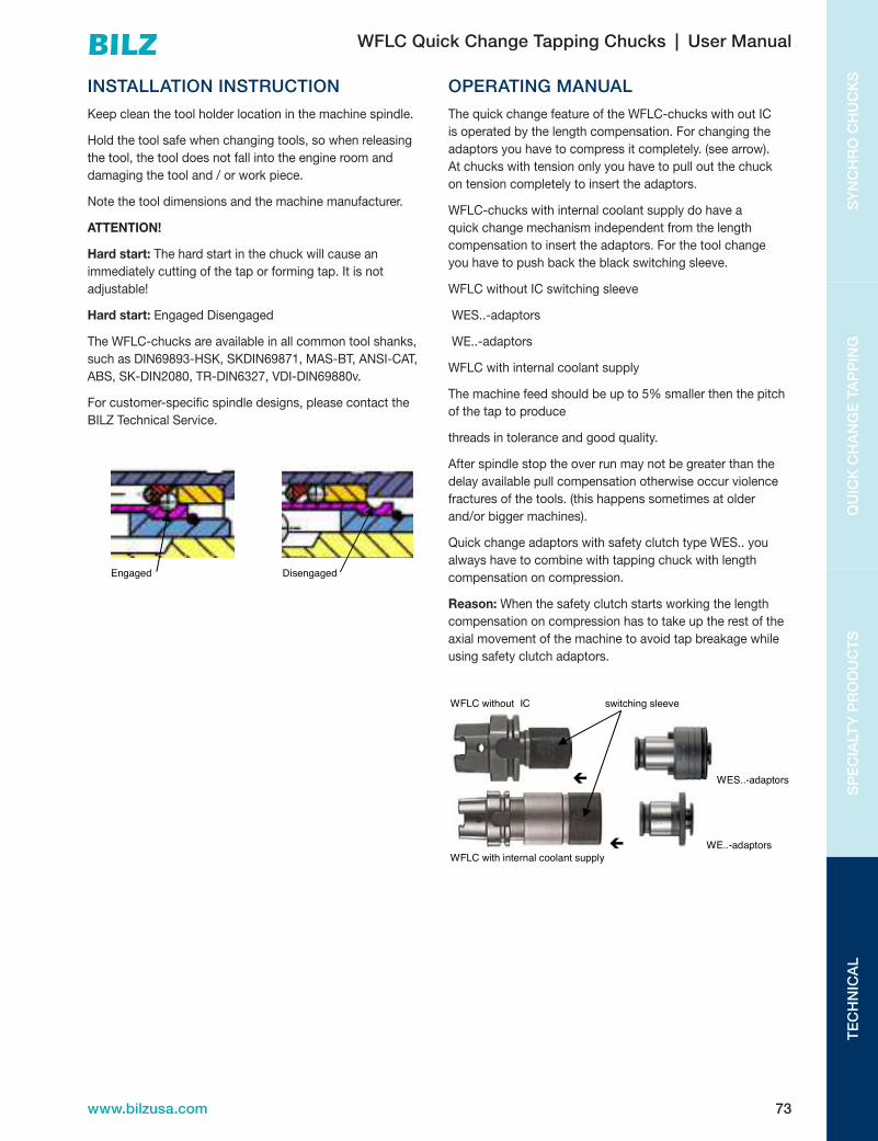
73www.bilzusa.com
TE
CH
NIC
AL
SP
EC
IALT
Y P
RO
DU
CT
SQ
UIC
K C
HA
NG
E T
AP
PIN
GS
YN
CH
RO
CH
UC
KS
WFLC Quick Change Tapping Chucks | User Manual
INSTALLATION INSTRUCTION
Keep clean the tool holder location in the machine spindle.
Hold the tool safe when changing tools, so when releasing the tool, the tool does not fall into the engine room and damaging the tool and / or work piece.
Note the tool dimensions and the machine manufacturer.
ATTENTION!
Hard start: The hard start in the chuck will cause an immediately cutting of the tap or forming tap. It is not adjustable!
Hard start: Engaged Disengaged
TheWFLC-chucksareavailableinallcommontoolshanks,suchasDIN69893-HSK,SKDIN69871,MAS-BT,ANSI-CAT,ABS,SK-DIN2080,TR-DIN6327,VDI-DIN69880v.
For customer-specific spindle designs, please contact the BILZTechnicalService.
OPERATING MANUAL
ThequickchangefeatureoftheWFLC-chuckswithoutICis operated by the length compensation. For changing the adaptors you have to compress it completely. (see arrow). At chucks with tension only you have to pull out the chuck on tension completely to insert the adaptors.
WFLC-chuckswithinternalcoolantsupplydohaveaquick change mechanism independent from the length compensation to insert the adaptors. For the tool change you have to push back the black switching sleeve.
WFLCwithoutICswitchingsleeve
WES..-adaptors
WE..-adaptors
WFLCwithinternalcoolantsupply
Themachinefeedshouldbeupto5%smallerthenthepitchof the tap to produce
threads in tolerance and good quality.
After spindle stop the over run may not be greater than the delay available pull compensation otherwise occur violence fractures of the tools. (this happens sometimes at older and/or bigger machines).
Quick change adaptors with safety clutch type WES.. you always have to combine with tapping chuck with length compensation on compression.
Reason: When the safety clutch starts working the length compensation on compression has to take up the rest of the axial movement of the machine to avoid tap breakage while using safety clutch adaptors.
Installation and operating instructions
WFLC quick change tapping chucks
in combination with quick change tapping adaptors type WE... / WES...
...
Scope and areas of applicationFor tapping and forming in combination with quick change adaptors on turning-, drilling-, milling machines as well as machining centres, multi spindle heads and special purpose machines. Used horizontally or vertically and for left-or right-hand threads.
WFLC..-..K/... versions with internal coolant supply and hydraulic static pressure compensation are suitable for coolant pressures up to 50bar.
We are pleased that you have decided on a product.
This manual describes the proper use and handling of the product.
Read the instructions carefully before use and use the product only in the manner specified by us.
Important information!
To prevent damage or injury, please follow the instructions exactly.
Tool change only with standing spindle!
Do not disassemble the products and do not make any modifications. This may result in damage and malfunction!
Use only tapping chucks and adaptors of BILZ company. The combination with other products may cause damage or malfunction!
The tapping chucks are maintenance-free, should there be any faults, please use do not continue using the products. Please contact the Technical Service of the company BILZ.
Cleaning: Periodically, we recommend to clean the chucks with a cleaning rag. This depends on the degree of contamination. Do not use any aggressive solvent. No use of fibrous materials like e.g. cleaning wool.
Out of operation: If the chuck is taken out of operation, note the following. Clean the chuck with a cleaning rag. Spray or rub the chuck with a preservation oil, to prevent the formation of rust and preserve the smoothness of the chuck. Prior to storage, coolant and processing residues should be removed.
Use the product only for the recommended application of BILZ.
If you do have any questions please contact BILZ. www.bilz.de BILZ Werkzeugfabrik GmbH&Co.KG, 73760 Ostfildern, Vogelsangstr. 8 Fon: +49 711 34801 0; Fax: +49 711 34801 88; Mail: [email protected]
Version E1
Installation Instruction
Keep clean the tool holder location in the machine spindle.
Hold the tool safe when changing tools, so when releasing the tool, the tool does not fall into the engine room and damaging the tool and / or work piece.
Note the tool dimensions and the machine manufacturer.
Attention!
Hard start: The hard start in the chuck will cause an immediately cutting of the tap or forming tap. It is not adjustable!
Hard start:
Engaged Disengaged
The WFLC-chucks are available in all common locations like (DIN69893-HSK ,SK-DIN69871, MAS-BT, ANSI-CAT, ABS, SK-DIN2080, TR-DIN6327, VDI-DIN69880).
For customer-specific spindle designs, please contact the Technical Service of the company BILZ.
Operating Manual
The quick change feature of the WFLC-chucks with out IC is operated by the length compensation. For changing the adaptors you have to compress it completely. (see arrow ). At chucks with tension only you have to pull out the chuck on tension completely to insert the adaptors. WFLC-chucks with internal coolant supply do have a quick change mechanism independent from the length compensation to insert the adaptors. For the tool change you have to push back the black switching sleeve.
WFLC without IC switching sleeve
WES..-adaptors
WE..-adaptors WFLC with internal coolant supply
The machine feed should be up to 5% smaller then the pitch of the tap to produce threads in tolerance and good quality.
After spindle stop the over run may not be greater than the delay available pull compensation otherwise occur violence fractures of the tools. (this happens sometimes at older and / or bigger machines).
Quick change adaptors with safety clutch type WES.. you always have to combine with tapping chuck with length compensation on compression. Reason: When the safety clutch starts working the length compensation on com-pression has to take up the rest of the axial movement of the machine to avoid tap breakage while using safety clutch adaptors .

74 www.bilzusa.com
SY
NC
HR
O C
HU
CK
SQ
UIC
K C
HA
NG
E TA
PP
ING
SP
EC
IALT
Y P
RO
DU
CT
ST
EC
HN
ICA
L
Tool Clamping Options and Values | Technical Information
CHARACTERISTIC END MILL HOLDER DA COLLET CHUCKS SC COLLET CHUCKS ER COLLET CHUCKS HP COLLET CHUCKS MILLING CHUCKS HYDRAULICS CHUCKS SHRINK FIT CHARACTERISTIC
PRECISION 1 1 2 3 4 4 5 5 PRECISIONToolholder precision
is based on run out or TIR from centerline on
rotation axis at the shank and cutting tool tip/edge
Lowestprecisiondueto bore tolerances,
diametrical clearance and side lock screw forces.
Lowerprecisiondue to design and gripping accuracy.
Single angle design lends itself to high gripping
strength and accuracy.
Highest single angle collet accuracy and solid carbide tool shank grip.
Highest single angle collet accuracy with close tolerance collet ID sizes
for TIR improvement
Precision achieved is based on collet accuracy
and torque value of assembled system
High TIR accuracy due system design and
manufacturing tolerances to rotational centerline
Highest TIR accuracy of all clamping systems.
Toolholder precision is based on run out or TIR from centerline on rotation axis at the shank and cutting tool tip/edge
VERSATILITY 1 3 5 5 4 4 1 1 VERSATILITYExpanse of use is based
on the capability to clamp multiple tool shank
diameters and styles
One size per tool limited to same size tool shank.
The DA (double angle) collet system has
three collet size ranges accommodating
shanksizesto3/4"maximum diameter.
SC (PG or TG) single angle collet systems
have three series sizes accommodating tool shank sizes to a maximumof1.500"diameter tool shank.
ER collet system is based on metric nominal
sizes and has a tool angle different than the SC collet system. ER collets are available in six different sizes and
can accommodate tool shanks to a maximum of 1.181"diametershank.
Same as ER collet system but with
highest TIR accuracy through a controlled
manufacturing process.
Reduction collet system designed to operate in
conjunction with the roller bearing clamping system design in the collet nut
Single size ID per tool clamping system. Accommodates a single shank size
Single size ID that accommodates a single size tool shank requiring H6orH7shanktolerance
Expanse of use is based on the capability to clamp multiple tool shank diameters and styles
TOOL CLAMPING 1 2 4 3 3 4 4 5 TOOL CLAMPINGRIGIDITY Minimal rigidity due
to set screw design clamp cutting tool shank off center.
Median tool rigidity due to limit tool shank
clamping force of DA collet design.
Best collet grip strength due to design. 3to1torquevalue
on tool shank.
Good collet grip strength due to design. 2to1torquevalue
on tool shank.
Good collet grip strength duetodesign.2to1torque value on tool
shank. Collet collapse restriction limits rigidity
Strongest gripping collet system. Gripping strength
is nearest thermal clamping strength
Good clamping rigidityfor“Z”axis
use only. Radial loads can damage internal
hydraulic sleeve design.
RIGIDITYHow rigid is the cutting
tool shank secured in the body of the holder
under cutting tool loads and RPM changes.
How rigid is the cutting tool shank secured in the body of the holder under cutting tool loads and RPM changes.
EASE OF USE 4 3 2 2 1 3 2 4 EASE OF USEEase of use is based
on the simplicity of the “clamping system”
to be assembled and disassembled with
the cutting tools.
1or2setscrewsrequired to secure tool shank in tool holder.
May assemble tool, collet and collet nut
in any sequence.
Requires collet to be inserted in collet nut
before tool shank can be inserted into collet and then into tool holder body.
Requires collet to be inserted in collet nut
before tool shank can be inserted into collet and then into tool holder body.
Requires collet to be inserted in collet nut
before tool shank can be inserted into collet
and then into tool holder body. HP ER collets have limited
collet collapse range.
Reduction collet system. Tool insertion is completed and then
pressure clamp screw is adjusted to increase
“hydraulic” camp forces surrounding the sleeve holding the tool shank.
Requires shrink fit machine to heat the tool clamping bore allowing
tool shank insertion.
Ease of use is based on the simplicity of the “clamping system” to be assembled and disassembled with the cutting tools.
RELIABILITY 3 3 3 3 4 4 4 5 RELIABILITYHow reliable is the
“clamping system” to maintain the required
optimal precision for the assembled system.
End mill holders require minimal
maintenance other than ID bore integrity.
Regular cleaning of collet surface and collet body surfaces. Care of collets is most critical.
Regular cleaning of collet surface and collet body surfaces. Care of collets is most critical.
Regular cleaning of collet surface and collet body surfaces. Care of collets is most critical.
Regular cleaning of collet surface and collet body surfaces. Care of collets is most critical.
Regular cleaning of collet surface and collet body surfaces. Care of collets is most critical.
Regular cleaning of bore required. Only solid
and cylindrical shanks with no voids can be used in this system.
No mechanical parts to wear out or
be maintained.
How reliable is the “clamping system” to maintain the required optimal precision for the assembled system.
HIGH RPM/ 1 1 2 3 4 3 4 5 HIGH RPM/TOOL BALANCE End mill holders by
design are unbalanced and unstable at
high RPM.
Lackofcolletprecisiondesign and collet nut
design makes DA system weak at high RPM.
Concentric collet and collet body design allow for moderate RPM use but collet nut design
limits high RPM usage.
Concentric collet and collet body design allow for moderate RPM use but collet nut design
limits high RPM usage.
Concentric collet and collet body design allow for moderate RPM use but collet nut design
limits high RPM usage.
Concentric collet and collet body design allow for moderate RPM use but collet nut design
limits high RPM usage.
Body design and “fluid clamping” system limits
high RPM usage.
No mechanical parts and designed for balance stability at high RPM.
TOOL BALANCEAs machining RPM
increase, tool balance is important. Value based
on ability to maintain tool balance at high RPM.
As machining RPM increase, tool balance is important. Value based on ability to maintain tool balance at high RPM.
ECONOMY/COST 5 4 4 3 2 2 5 3 ECONOMY/COSTCost or purchased
value of the tool clamping system.
Lowestcosttoolholder system.
Lowestcostcolletsystem due to lower
precision system.
Median price tool holding system but
must secure collet as well TG/PG collets price
similar to ER collets.
Median price tool holding system but
must secure collet as well TG/PG collets price
similar to ER collets.
Median price tool holding system but must secure collet. HP (PG/TG HP or ER HP) are higher cost than standard collets.
Higher cost of holder due to design and clamping system.
Most expensive tool clamping system.
Median price of tool holder but shrink fit machine needs to be purchased to support the system.
Cost or purchased value of the tool clamping system.
VALUE 1 2 2 3 4 4 3 5 VALUEValue of the productivity
and tool performance gained from the
assembled system.
While the most economical purchase, this tool style can be
the most costly due to it’s low TIR and limited
applications of tool sizes and RPM capabilities.
While this was the “original collet chuck system” it is limited in its accuracy and
rigidity. It is great for narrow clearances and
drilling applications.
This product was the 2ndgenerationofcolletsystems and is widely
used today. Its gripping strength is the highest of SC or ER collet systems. One issue still remains and that is the shank engagement required
for carbide shank tools.
The most flexible and accurate of the collet
systems that are considered “industry
standard” today. Good tool shank
gripping strength and high accuracy with
regards to TIR.
Same as the ER collet system but with higher
TIR accuracy. Much more costly collets that
standard ER style collets.
Great tool shank gripping strength and
excellent TIR accuracy. Excellent value for
large shank tools and high radial tool loads
when using heavy feed rates.Largenoselimitsclearances in pockets.
Highestaccuracyfor“Z”axis drilling. Expensive tool that usually needs
replacement every 3-5years.Limited
uses for end milling as radial lows must be
light to reduce risk of damaging holder bore.
After investment is made, this system offers all
the productivity benefits for milling, drilling, and
reaming. Most rigid, highest TIR accuracy, and best tool gripping strength of all clamping systems. Best overall value when considering tooling cost
with productivity and part accuracy achievements.
Value of the productivity and tool performance gained from the assembled system.

75www.bilzusa.com
TE
CH
NIC
AL
SP
EC
IALT
Y P
RO
DU
CT
SQ
UIC
K C
HA
NG
E T
AP
PIN
GS
YN
CH
RO
CH
UC
KS
Tool Clamping Options and Values | Technical Information
CHARACTERISTIC END MILL HOLDER DA COLLET CHUCKS SC COLLET CHUCKS ER COLLET CHUCKS HP COLLET CHUCKS MILLING CHUCKS HYDRAULICS CHUCKS SHRINK FIT CHARACTERISTIC
PRECISION 1 1 2 3 4 4 5 5 PRECISIONToolholder precision
is based on run out or TIR from centerline on
rotation axis at the shank and cutting tool tip/edge
Lowestprecisiondueto bore tolerances,
diametrical clearance and side lock screw forces.
Lowerprecisiondue to design and gripping accuracy.
Single angle design lends itself to high gripping
strength and accuracy.
Highest single angle collet accuracy and solid carbide tool shank grip.
Highest single angle collet accuracy with close tolerance collet ID sizes
for TIR improvement
Precision achieved is based on collet accuracy
and torque value of assembled system
High TIR accuracy due system design and
manufacturing tolerances to rotational centerline
Highest TIR accuracy of all clamping systems.
Toolholder precision is based on run out or TIR from centerline on rotation axis at the shank and cutting tool tip/edge
VERSATILITY 1 3 5 5 4 4 1 1 VERSATILITYExpanse of use is based
on the capability to clamp multiple tool shank
diameters and styles
One size per tool limited to same size tool shank.
The DA (double angle) collet system has
three collet size ranges accommodating
shanksizesto3/4"maximum diameter.
SC (PG or TG) single angle collet systems
have three series sizes accommodating tool shank sizes to a maximumof1.500"diameter tool shank.
ER collet system is based on metric nominal
sizes and has a tool angle different than the SC collet system. ER collets are available in six different sizes and
can accommodate tool shanks to a maximum of 1.181"diametershank.
Same as ER collet system but with
highest TIR accuracy through a controlled
manufacturing process.
Reduction collet system designed to operate in
conjunction with the roller bearing clamping system design in the collet nut
Single size ID per tool clamping system. Accommodates a single shank size
Single size ID that accommodates a single size tool shank requiring H6orH7shanktolerance
Expanse of use is based on the capability to clamp multiple tool shank diameters and styles
TOOL CLAMPING 1 2 4 3 3 4 4 5 TOOL CLAMPINGRIGIDITY Minimal rigidity due
to set screw design clamp cutting tool shank off center.
Median tool rigidity due to limit tool shank
clamping force of DA collet design.
Best collet grip strength due to design. 3to1torquevalue
on tool shank.
Good collet grip strength due to design. 2to1torquevalue
on tool shank.
Good collet grip strength duetodesign.2to1torque value on tool
shank. Collet collapse restriction limits rigidity
Strongest gripping collet system. Gripping strength
is nearest thermal clamping strength
Good clamping rigidityfor“Z”axis
use only. Radial loads can damage internal
hydraulic sleeve design.
RIGIDITYHow rigid is the cutting
tool shank secured in the body of the holder
under cutting tool loads and RPM changes.
How rigid is the cutting tool shank secured in the body of the holder under cutting tool loads and RPM changes.
EASE OF USE 4 3 2 2 1 3 2 4 EASE OF USEEase of use is based
on the simplicity of the “clamping system”
to be assembled and disassembled with
the cutting tools.
1or2setscrewsrequired to secure tool shank in tool holder.
May assemble tool, collet and collet nut
in any sequence.
Requires collet to be inserted in collet nut
before tool shank can be inserted into collet and then into tool holder body.
Requires collet to be inserted in collet nut
before tool shank can be inserted into collet and then into tool holder body.
Requires collet to be inserted in collet nut
before tool shank can be inserted into collet
and then into tool holder body. HP ER collets have limited
collet collapse range.
Reduction collet system. Tool insertion is completed and then
pressure clamp screw is adjusted to increase
“hydraulic” camp forces surrounding the sleeve holding the tool shank.
Requires shrink fit machine to heat the tool clamping bore allowing
tool shank insertion.
Ease of use is based on the simplicity of the “clamping system” to be assembled and disassembled with the cutting tools.
RELIABILITY 3 3 3 3 4 4 4 5 RELIABILITYHow reliable is the
“clamping system” to maintain the required
optimal precision for the assembled system.
End mill holders require minimal
maintenance other than ID bore integrity.
Regular cleaning of collet surface and collet body surfaces. Care of collets is most critical.
Regular cleaning of collet surface and collet body surfaces. Care of collets is most critical.
Regular cleaning of collet surface and collet body surfaces. Care of collets is most critical.
Regular cleaning of collet surface and collet body surfaces. Care of collets is most critical.
Regular cleaning of collet surface and collet body surfaces. Care of collets is most critical.
Regular cleaning of bore required. Only solid
and cylindrical shanks with no voids can be used in this system.
No mechanical parts to wear out or
be maintained.
How reliable is the “clamping system” to maintain the required optimal precision for the assembled system.
HIGH RPM/ 1 1 2 3 4 3 4 5 HIGH RPM/TOOL BALANCE End mill holders by
design are unbalanced and unstable at
high RPM.
Lackofcolletprecisiondesign and collet nut
design makes DA system weak at high RPM.
Concentric collet and collet body design allow for moderate RPM use but collet nut design
limits high RPM usage.
Concentric collet and collet body design allow for moderate RPM use but collet nut design
limits high RPM usage.
Concentric collet and collet body design allow for moderate RPM use but collet nut design
limits high RPM usage.
Concentric collet and collet body design allow for moderate RPM use but collet nut design
limits high RPM usage.
Body design and “fluid clamping” system limits
high RPM usage.
No mechanical parts and designed for balance stability at high RPM.
TOOL BALANCEAs machining RPM
increase, tool balance is important. Value based
on ability to maintain tool balance at high RPM.
As machining RPM increase, tool balance is important. Value based on ability to maintain tool balance at high RPM.
ECONOMY/COST 5 4 4 3 2 2 5 3 ECONOMY/COSTCost or purchased
value of the tool clamping system.
Lowestcosttoolholder system.
Lowestcostcolletsystem due to lower
precision system.
Median price tool holding system but
must secure collet as well TG/PG collets price
similar to ER collets.
Median price tool holding system but
must secure collet as well TG/PG collets price
similar to ER collets.
Median price tool holding system but must secure collet. HP (PG/TG HP or ER HP) are higher cost than standard collets.
Higher cost of holder due to design and clamping system.
Most expensive tool clamping system.
Median price of tool holder but shrink fit machine needs to be purchased to support the system.
Cost or purchased value of the tool clamping system.
VALUE 1 2 2 3 4 4 3 5 VALUEValue of the productivity
and tool performance gained from the
assembled system.
While the most economical purchase, this tool style can be
the most costly due to it’s low TIR and limited
applications of tool sizes and RPM capabilities.
While this was the “original collet chuck system” it is limited in its accuracy and
rigidity. It is great for narrow clearances and
drilling applications.
This product was the 2ndgenerationofcolletsystems and is widely
used today. Its gripping strength is the highest of SC or ER collet systems. One issue still remains and that is the shank engagement required
for carbide shank tools.
The most flexible and accurate of the collet
systems that are considered “industry
standard” today. Good tool shank
gripping strength and high accuracy with
regards to TIR.
Same as the ER collet system but with higher
TIR accuracy. Much more costly collets that
standard ER style collets.
Great tool shank gripping strength and
excellent TIR accuracy. Excellent value for
large shank tools and high radial tool loads
when using heavy feed rates.Largenoselimitsclearances in pockets.
Highestaccuracyfor“Z”axis drilling. Expensive tool that usually needs
replacement every 3-5years.Limited
uses for end milling as radial lows must be
light to reduce risk of damaging holder bore.
After investment is made, this system offers all
the productivity benefits for milling, drilling, and
reaming. Most rigid, highest TIR accuracy, and best tool gripping strength of all clamping systems. Best overall value when considering tooling cost
with productivity and part accuracy achievements.
Value of the productivity and tool performance gained from the assembled system.

we hold our promise
www.bi lzusa .com | 1140 N. Main Street | Lombard, IL 60148 | 847-734-9390
We’ll Take You Where You Need to Go. All of our products are “best in class” technologies that help our
customers remain competitive and profitable. We have something
thatcanhelpyoutoo!Learnmoreatwww.bilzusa.com.
The Latest Technology. The Best Quality. Extensive Product Support .We hold our promise in three important ways: First,bydeliveringthemostadvancedtoolclampingtechnologyavailable;Second,bymaintainingthehighestlevelofquality;Third,byprovidingthestrongestproduct,applicationandengineeringsupport in the industry. Let us prove it! Bilz Tool Company, Inc.
09/201
3