tapi
20
Software Reference Telephony Services 1 1TELEPHONY SERVICES August 2000
description
tapi
Transcript of tapi

1TELEPHONY
SERVICESAugust 2000
Software Reference Telephony Services 1

2 Telephony Services Software Reference
Table of Contents
Table of Contents
TELEPHONY SERVICES
A REFERENCE 5
1 Telephony Services on The BinTec router 6
1.1 Overview 6
1.2 What is POTS? 7
1.2.1 POTS Interfaces 8
1.3 What is TAPI? 12
1.3.1 Remote TAPI on the BinTec router 13
1.4 Configuring Telephony Services 15
1.4.1 Two workspaces: two telephones, one V!CAS 15
1.4.2 One workspace: one V!CAS, one telephone, one fax 19
Software Reference Telephony Services 3

Table of Contents
4 Telephony Services Software Reference

A
AREFERENCE
Software Reference Telephony Services 5

Telephony Services on The BinTec routerA
1 Telephony Services on The BinTecrouter
1.1 Overview
Telephony Service on the BinTec router means that you canconnect conventioanal analog devices (telephone, fax, mo-dem, etc.) to the BinTec router and place or receive analogcalls via any of the BinTec router’s ISDN interfaces.
This allows you to use the BinTec router as a PBX (Pri-vate Branch exchange) to:
1. Make toll-free calls internally between connectedanalog devices, or
2. Place (or receive) calls via the ISDN from connectedanalog devices.
NOTE: System software support for telephony services isincluded on all BinTec router products. However, to takeadvantage of telephony services, a CM-AB module mustbe installed.
6 Telephony Services Software Reference

What is POTS? A
This could be useful for small offices when combinedwith PCs running Remote TAPI Client software (includedon the Companion CD).
In the simple scenario shown above, the BinTec router isused to make inter-office (toll-free) calls between worksta-tions using the internal telephone numbers. In addition,both parties can simultaneously place or receive calls fromthe ISDN using their respective analog devices.
Although telephony services and the Remote TAPI go to-gether hand in hand, the rest of this chapter describes usingthe BinTec router’s POTS ports and using the BinTec routeras a Remote TAPI Server separately.
1.2 What is POTS?
In the networking field the term POTS (Plain Old Tele-phone Service) is often used to refer to the conventional an-alog telephone network or analog-based communicationsdevices. With the CM-AB module installed the BinTec rout-er has two POTS ports on it’s backplane called POTS A andPOTS B, for the attachment of such devices (analog tele-phone, FAX machine, or modem).
Sales Officer Customer Service
Pots A Pots B
ISDN
External Number = 5022Internal Number = *1
External Number = 5023Internal Number = *2
Representative
Software Reference Telephony Services 7

Telephony Services on The BinTec routerA
1.2.1 POTS Interfaces
When the CM-AB module is installed an entry in the bi-boAdmBoardTable will display the slot number where theboard is installed. On the V!CAS and the BRICK-XS Officeslot 3 is always used. Information about the devices con-nected to the POTS ports is stored in the potsIfTable. On theV!CAS the table looks as follows.
The fields of the potsIfTable have the following mean-ings.
Slot Identifies the slot the CM-AB module is installedin.
Unit Identifies the port, POTS A = Unit 0,POTS B = Unit 1.
Type Identifies the types of calls this device willaccept.Possible values include: any, telephony, fax,modem, or disable.Disable means that the device can not place oraccept calls.
These are the default entries created by the system atboot time upon detection of an installed CM-AB module.potsIfTable entries can only be removed by the system.
mybrick: > potsIfTable
inx Slot(*ro) Unit(*ro) Type(rw)
00 3 0 any
01 3 1 any
mybrick : potsIfTable>
8 Telephony Services Software Reference

What is POTS? A
Dispatching Analog Calls
The BinTec router dispatches incoming calls (from the IS-DN) according to the ISDN Call Dispatching algorithm.The dispatching algorithm distributes calls to BinTec routerservices according to the "Called Party’s Address" con-tained in the call packet and the localNumber field of the is-dnDispatchTable. Calls dispatched to the pots service(Item=pots) are given to POTS devices based on additionalinformation contained in the service indicator field of theISDN Call packet and the Type field mentioned above. Theservice indicator field simplay specifies the type (FAX,voice, data , etc.) of call.
The different call types and the services they support areas follows:
Internal Calls
Internal calls can be made between devices connected to theBinTec router’s POTS ports. This requires that each POTSdevice in the connection is assigned an internal number ).Note that these calls are dispatched according to the isd-
NOTE If the call originated from an analog device, the ISDN can’talways accurately report the call type and simply reportsthe call as being an "analog" call; the actual call may be aFAX or voice call.
potsTypeAccepts calls from
analog network ISDN devices
any analog telephony, fax, modem
telephony analog telephony
fax analog fax
modem analog modem
Software Reference Telephony Services 9

Telephony Services on The BinTec routerA
nDispatchTable; therefore it’s recommended that you as-sign internal numbers using the format "* <internalnumber>" to ensure internal and external MSNs are keptseparate. Internal numbers are assigned to devices in the is-dnDispatchTable as follows.
External CallsExternal calls can also be placed or received from POTS de-vices. External numbers are assigned to POTS devices in thesame way as for internal numbers with the exception thatthe StkNumber field must specify a "real" ISDN Stacknumber.
isdnDispatchTable POTS A POTS B
StkNumber 31
Item pots
LocalNumber <the telephone number for this device>
Bearer any
Slot <slot number for CM-AB module>
Unit 0 1
Direction both
Mode
UserName
NOTE By default the BinTec router automatically creates two dis-patch table entries upon detection of the CM-AB moduleat boot time. The default internal numbers for ports A andB are "*1" and "*2" respectively.
10 Telephony Services Software Reference

What is POTS? A
Outbound External CallsEach POTS device must have exactly one outgoingnumber for outbound external calls. This means either
1. an external number entry with the Direction fieldset to both OR
2. an external number entry with the Direction set tooutgoing .
Inbound External CallsA POTS device may be configured to respond to differ-ent external numbers by creating multiple external-number entries in the dispatch table and setting the Di-rection field to incoming .
Software Reference Telephony Services 11

Telephony Services on The BinTec routerA
1.3 What is TAPI?
TAPI (Telephony Applications Programming Interface) is aprogramming interface initially defined by Microsoft andIntel for developing Windows-based telephony applica-tions. A telephony application uses attached telephoneequipment to place, accept, or monitor calls. The MicrosoftDialer (part of Windows) is an example of a TAPI applica-tion.
TAPI actually consists of two parts.
1. The API defines how applications (like the Micro-soft Dialer) interact with the underlying operatingsystem (Windows 95 or NT).It gives applications access to Windows’ telephonyfeatures.
2. The SPI (Service Provider Interface) defines howthe operating system interacts with attached te-lephony hardware. More than one TSP (TelephoneService Provider) may be installed on the PC, eachone specifies how the OS communicates with a pat-icular piece of hardware.
12 Telephony Services Software Reference

What is TAPI? A
TAPI on Windows 95 and NT systems looks like this.
1.3.1 Remote TAPI on the BinTec router
The BinTec router can be used as a remote TAPI server,meaning that it can place, accept, and route calls from a PCon the LAN where the Remote TAPI Client is installed. Re-mote TAPI Client software for PCs is included on the Com-panion CD and is installed from the BRICKware installa-tion program.
The Remote TAPI Client forwards all TAPI requestsmade by TAPI applications to the BinTec router via a TCPstream.
TelephonyApplication
API
SPI
tapi.dll(16 bit apps)
tapi32.dll(32 bit apps)
unimdm.tsp rtc_tsp.tsp wan.tsp
TAPI
TelephonyApplication
TelephonyApplication
Both dlls areshipped with Win95 and NT. Win-dows uses the ap-propriate dll de-pending on theuser’s application(16 or 32 bit).
Hardware specific*.tsp and *.exefiles provided bythe equipmentmanufacturer.
Win
do
ws
95 /
NT
Software Reference Telephony Services 13

Telephony Services on The BinTec routerA
The BinTec router accepts TAPI client connections via it’sTAPI port.
TAPI Settings
Configuring the BinTec router as a TAPI server is straight-forward. On the BinTec router, all that is required is that theBinTec router’s TAPI port be set. This is defined in the ad-min table.
The biboAdmTapiTcpPort variable defines the TCP porton the BinTec router remote TAPI applications must con-nect to. By default the BinTec router uses TCP Port 6001.The same value must be configured on the PC running theRemote TAPI Client program.
The TAPI server can be disabled completely by settingthe TAPI port to 0.
Remote
brick.tspWin NT:
Win 95:
rtc32ui.exertc32.tsp
tapi2wsa.exertc_spi.tsp
biboAdmTapiTcpPort
TAPI ClientRemote
TAPI Server
Pots A
Pots B
TCP Stream
14 Telephony Services Software Reference

Configuring Telephony Services A
1.4 Configuring Telephony Services
Below are two example configurations showing how theBinTec router can be used as a simple PBX. The RemoteTAPI Client could be installed on the computers in these ex-amples allowing calls to be managed directly from the PC.
1.4.1 Two workspaces: two telephones, one V!CAS
Here we have two workspaces, a Sales Agent and a Cus-tomer Service Representative. Each workspace has an ana-log telephone that is connected to the BinTec router. Thesample configuration shows the entries that would bemade to the isdnDispatchTable to allow:
1. Both workspaces receive incoming ISDN callsplaced to 5021,i.e., both phones ring, the first one to pick up getsthe call.
2. Each workspace has a separate number for directcalls.
3. Internal calls can be placed between workspaces.
Sales Officer Customer Service
Pots A Pots B
ISDN
External numbers: 5021, 5022Internal number: *1
External numbers: 5021, 5023Internal number: *2
Representative
Software Reference Telephony Services 15

Telephony Services on The BinTec routerA
Step 1 Create the internal numbers by locating the entries for thePOTS A and POTS B interfaces in the isdnDispatchTable.There will be two entries that use Stack 31. You can identifythe A and B interfaces by the Slot:Unit combination. POTSA is always at Unit 0, and POTS B at Unit 1. By default,POTS A uses the internal number "*1" while POTS B uses"*2". Since the default values are what we want for our ourexample setup, we don’t need to change them.
Step 2 Create an entry for each device’s direct number.Only POTS A can answer calls to 5022; only POTS B can an-
mybrick: > isdnDispatchTableinx StkNumber(*rw) Item(*-rw) LocalNumber(rw)
LocalSubaddress(rw) Bearer(rw) Slot(rw)Unit(rw) Direction(rw) Mode(rw)UserName(rw)
00 31 pots "*1"any 3
0 both right_to_left"default"
01 31 pots "*2"any 3
1 both right_to_left"default"
mybrick : isdnDispatchTable>
16 Telephony Services Software Reference

Configuring Telephony Services A
swer calls to "5023". The first entry is for POTS A, the sec-ond POTS B.
Step 3 Create the entries for our common external number "5021."This will allow both device to receive calls placed to this
mybrick: isdnDispatchTable > StkNumber=0 Item=pots Slot=3 Unit=0 LocalNumber=5022Direction=both Mode=right_to_left UserName="default
mybrick: isdnDispatchTable > StkNumber=0 Item=pots Slot=3 Unit=1 LocalNumber=5023Direction=both Mode=right_to_left UserName="default
mybrick : isdnDispatchTable> isdnDispatchTableinx StkNumber(*rw) Item(*-rw) LocalNumber(rw)
LocalSubaddress(rw) Bearer(rw) Slot(rw)Unit(rw) Direction(rw) Mode(rw)UserName(rw)
02 0 pots "5022"any 3
0 both right_to_left"default"
03 0 pots "5023"any 3
1 both right_to_left"default"
mybrick : isdnDispatchTable>
Software Reference Telephony Services 17

Telephony Services on The BinTec routerA
number. Again, our first entry is for POTS A the second isfor POTS B.
The configuration is complete. Don’t forget to save yourchanges to a configuration file with cmd=save .
mybrick: isdnDispatchTable > StkNumber=0 Item=pots Slot=3 Unit=0 LocalNumber=5021Direction=incoming Mode=right_to_left User-
Name="default
mybrick: isdnDispatchTable > StkNumber=0 Item=pots Slot=3 Unit=1 LocalNumber=5021Direction=incoming Mode=right_to_left User-
Name="default
mybrick : isdnDispatchTable> isdnDispatchTableinx StkNumber(*rw) Item(*-rw) LocalNumber(rw)
LocalSubaddress(rw) Bearer(rw) Slot(rw)Unit(rw) Direction(rw) Mode(rw)UserName(rw)
04 0 pots "5021"any 3
0 incoming right_to_left"default"
05 0 pots "5021"any 3
1 incoming
mybrick : isdnDispatchTable>
18 Telephony Services Software Reference
Configuring Telephony Services A
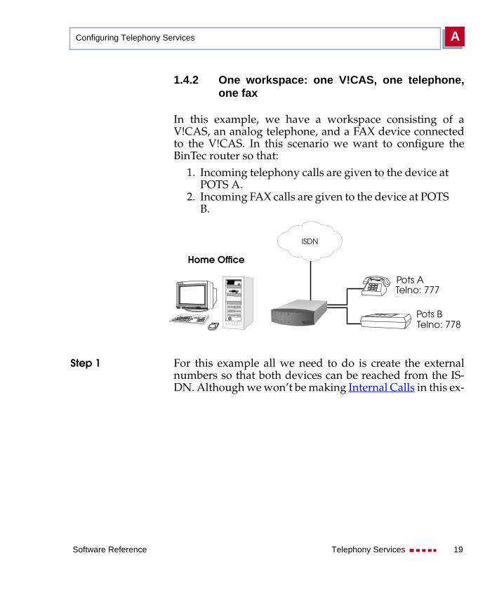
1.4.2 One workspace: one V!CAS, one telephone,one fax
In this example, we have a workspace consisting of aV!CAS, an analog telephone, and a FAX device connectedto the V!CAS. In this scenario we want to configure theBinTec router so that:
1. Incoming telephony calls are given to the device atPOTS A.
2. Incoming FAX calls are given to the device at POTSB.
Step 1 For this example all we need to do is create the externalnumbers so that both devices can be reached from the IS-DN. Although we won’t be making Internal Calls in this ex-
Pots A
Pots B
ISDN
Telno: 777
Telno: 778
Home Office
Software Reference Telephony Services 19

Telephony Services on The BinTec routerA
ample, the "Stack 31" entries will still be present in the isd-nDispatchTable.
mybrick: > isdnDispatchTableinx StkNumber(*rw) Item(*-rw) LocalNumber(rw)
LocalSubaddress(rw) Bearer(rw) Slot(rw)Unit(rw) Direction(rw)
02 0 pots "777"telephony 3
0 both
03 0 pots "778"fax 3
1 both
mybrick : isdnDispatchTable>
20 Telephony Services Software Reference