Taperloc Tech. - for pdf - Ormedic DE... · Engh Presentation, ... Place the retractable calcar...
14
taperloc ® : Spanning the generations surgical technique
-
Upload
truongminh -
Category
Documents
-
view
240 -
download
1
Transcript of Taperloc Tech. - for pdf - Ormedic DE... · Engh Presentation, ... Place the retractable calcar...

taperloc®:
Spanning the
generations
surgical technique
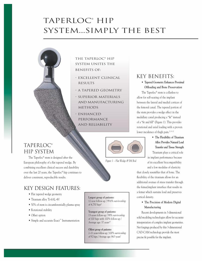
TAPERLOC® HIP SYSTEM
The Taperloc® stem is designed after the
European philosophy of a fl at tapered wedge. By
combining excellent clinical success and durability
over the last 20 years, the Taperloc® hip continues to
deliver consistent, reproducible results.
KEY DESIGN FEATURES:• Flat tapered wedge geometry
• Titanium alloy Ti-6AL-4V
• 50% of stem is circumferentially plasma spray
• Rotational stability
• Offset option
• Simple and accurate Exact™ Instrumentation
the taperloc® hip
system unites the
benefi ts of:
• excellent clinical
results
• a tapered geometry
• superior materials
and manufacturing
methods
• enhanced
performance
and reliability
taperloc® hip System...simply the best
• Tapered Geometry Enhances Proximal
Offl oading and Bone Preservation
The Taperloc® stem is collarless to
allow for self-seating of the implant
between the lateral and medial cortices of
the femoral canal. The tapered portion of
the stem provides a wedge effect in the
medullary canal producing a “fi t” instead
of a “fi t and fi ll” (Figure 1). This provides
rotational and axial loading with a proven
lower incidence of thigh pain.5, 9–11
• The Flexibility of Titanium
Alloy Provides Natural Load
Transfer and Tissue Strength
Titanium plays a critical role
in implant performance because
of its excellent biocompatibility
and a low modulus of elasticity
that closely resembles that of bone. The
fl exibility of the titanium allows for an
additional avenue of stress transfer through
the femur/implant interface that results in
a femur which sustains load and preserves
cortical density.
• The Precision of Modern Digital
Manufacturing
Recent developments in 3-dimensional
solid modeling technologies allow for accurate
interpretation of complex implant geometries.
Net forgings produced by this 3-dimensional
CAD-CAM technology provide the most
precise fi t possible for the implant.
Largest group of patients: 12-year follow-up / 99.6% survivorship of 4,750 hips6
Youngest group of patients:13-years follow-up / 98% survivorshipof 100 hips with 100% follow-up /Average age: 37 years10
Oldest group of patients:2–11 years follow-up / 100% survivorshipof 92 hips / Average age: 84.5 years7
Figure 1 – Flat Wedge & IM Rod
• Circumferential Plasma Spray Promotes
Better Initial Fixation and a More Complete Seal
Biomet’s circumferential plasma spray porous coating
is designed for optimal fi xation. The non-intercon-
nected pores act to create a seal from particulate
debris migration. This construct may reduce femoral
osteolysis and improve long-term fi xation.3, 4, 13
Biomet’s proprietary plasma spray application is
unique in that only the titanium alloy powder used
to create the coating is heated, while the implant’s
substrate is retained at near ambient temperatures.
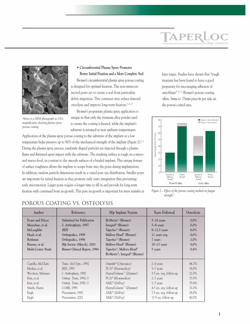
Application of the plasma spray porous coating to the substrate of the implant at a low
temperature helps preserve up to 90% of the mechanical strength of the implant (Figure 2).1, 2
During the plasma spray process, randomly shaped particles are injected through a plasma
fl ame and fl attened upon impact with the substrate. The resulting surface is rough on a micro-
and macro-level, in contrast to the smooth surfaces of a beaded implant. This unique feature
of surface roughness allows the implant to scrape bone into the pores during implantation.
In addition, random particle dimensions result in a varied pore size distribution. Smaller pores
are important for initial fi xation as they promote early osseo integration thus preventing
early micromotion. Larger pores require a longer time to fi ll in and provide for long-term
fi xation with continued bone in-growth. This pore in-growth is important for stress transfer at
1
Author Reference Hip Implant System Years Followed Osteolysis
Evans and DeLee Submitted for Publication Bi-Metric® (Biomet) 5–10 years 0.0% Mauerhan, et al. J. Arthroplasty, 1997 Integral® (Biomet) 5–8 years 0.0% McLaughlin JBJS Taperloc® (Biomet) 8–12.5 years 6.0% Head, et al. Orthopedics, 1999 Mallory-Head® (Biomet) 11 years avg. 0.0% Rothman Orthopedics, 1994 Taperloc® (Biomet) 7 years 3.0% Bourne, et al. Hip Society (March), 2001 Mallory-Head® (Biomet) 10–13 years 0.0% Multi-Center Study Biomet Clinical Report, 1994 Taperloc®, Mallory-Head® 5 years 0.4% Bi-Metric®, Integral® (Biomet) Capello, McClain Trans. Int’l Sym., 1992 Omnifi t® (Osteonics) 2–6 years 44.7% Heekin, et al. JBJS, 1993 PCA® (Howmedica) 5–7 years 18.0% Woolson, Maloney J. Arthroplasty, 1992 Harris/Galante™ (Zimmer) 3.5 yrs. avg. follow-up 22.0% Kim, et al. Orthop. Trans, 1992–3 PCA® (Howmedica) 2–7 years 37.0% Kim, et al. Orthop. Trans, 1992–3 AML® (DePuy) 2–7 years 55.8% Smith, Harris CORR, 1995 Harris/Galante™ (Zimmer) 4.5 yrs. avg. follow-up 31.0% Engh Presentation, 1992 AML® (DePuy) 7.5 yrs. avg. follow-up 28.0% Engh Presentation, 2001 AML® (DePuy) 13.9 yrs. follow-up 40.0%
POROUS COATING VS. OSTEOLYSIS
0
10
20
30
40
50
60
70
80
Sintered or Diffusion Bonded
Plasma Sprayed
Sintered or Diffusion Bonded
Plasma Sprayed
Ti and Ti Alloy Co-Cr Alloy
Fatig
ue S
treng
th (k
si) at
107 C
ycles
Range of values determinedRange of values reported
Figure 2 – Effect of the porous coating method on fatigue strength.8
Above is a SEM photograph at 100x magnifi cation showing plasma spray porous coating.
later stages. Studies have shown that “rough
titanium has been found to have a good
propensity for encouraging adhesion of
osteoblasts”.11, 12 Biomet’s porous coating
offers .5mm to .75mm press fi t per side on
the porous coated area.
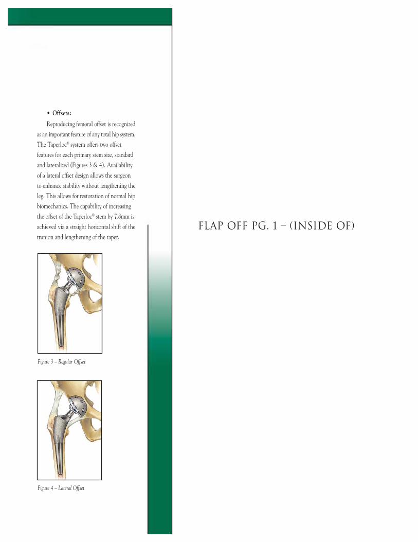
Figure 4 – Lateral Offset
Figure 3 – Regular Offset
• Offsets:
Reproducing femoral offset is recognized
as an important feature of any total hip system.
The Taperloc® system offers two offset
features for each primary stem size, standard
and lateralized (Figures 3 & 4). Availability
of a lateral offset design allows the surgeon
to enhance stability without lengthening the
leg. This allows for restoration of normal hip
biomechanics. The capability of increasing
the offset of the Taperloc® stem by 7.8mm is
achieved via a straight horizontal shift of the
trunion and lengthening of the taper.FLAP OFF PG. 1 – (INSIDE OF)
FLAP OFF PG. 1 – (BACK OF)
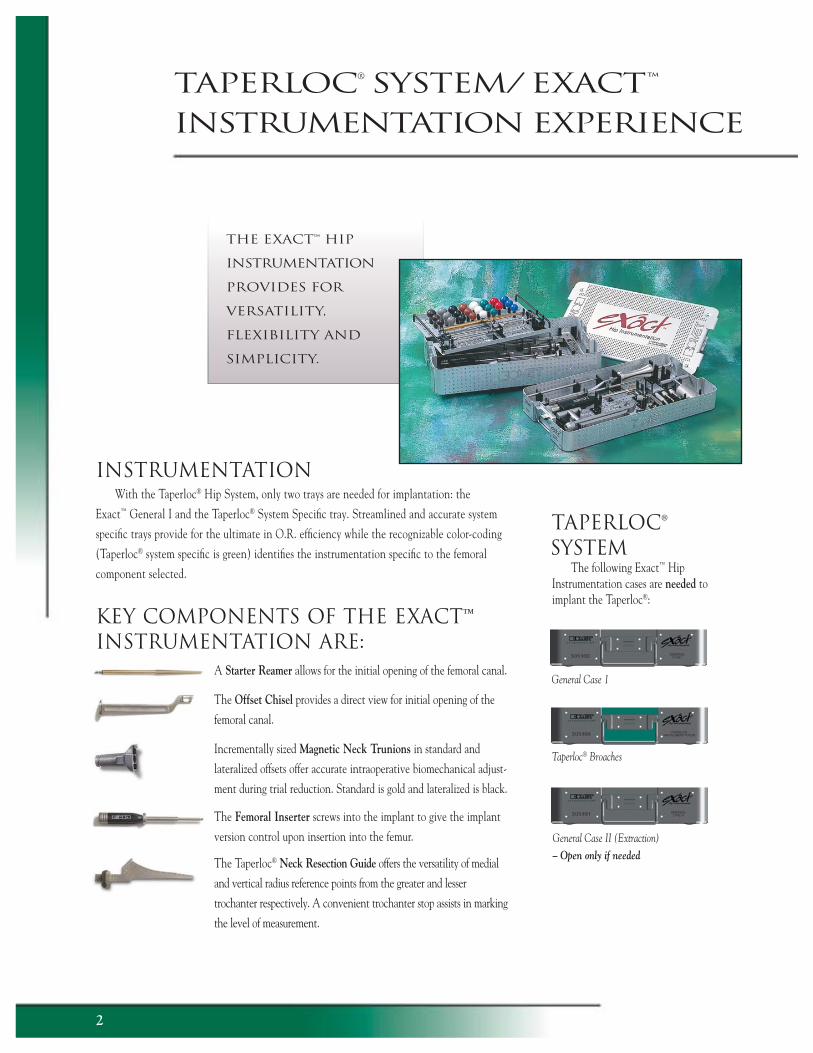
INSTRUMENTATIONWith the Taperloc® Hip System, only two trays are needed for implantation: the
Exact™ General I and the Taperloc® System Specifi c tray. Streamlined and accurate system
specifi c trays provide for the ultimate in O.R. effi ciency while the recognizable color-coding
(Taperloc® system specifi c is green) identifi es the instrumentation specifi c to the femoral
component selected.
KEY COMPONENTS OF THE EXACT™ INSTRUMENTATION ARE: A Starter Reamer allows for the initial opening of the femoral canal.
The Offset Chisel provides a direct view for initial opening of the
femoral canal.
Incrementally sized Magnetic Neck Trunions in standard and
lateralized offsets offer accurate intraoperative biomechanical adjust-
ment during trial reduction. Standard is gold and lateralized is black.
The Femoral Inserter screws into the implant to give the implant
version control upon insertion into the femur.
The Taperloc® Neck Resection Guide offers the versatility of medial
and vertical radius reference points from the greater and lesser
trochanter respectively. A convenient trochanter stop assists in marking
the level of measurement.
the exact™ hip
instrumentation
provides for
versatility,
fl exibility and
simplicity.
General Case 1
The following Exact™ Hip Instrumentation cases are needed to implant the Taperloc®:
Taperloc® Broaches
General Case II (Extraction) – Open only if needed
taperloc® System/ exact™ instrumentation experience
2
A Broach Handle provides solid engagement with a quick,
easy trigger locking mechanism that affords a clear view and a
rapid release. A large impaction plate provides
for solid driving contact.
Broaches are fully toothed to provide the effi cient
removal of cancellous bone to contour a pocket for
the implant. These newly designed broaches are
created utilizing the same data set used to produce
the implant. Included is an improved cutting tooth
pattern that is nitrided to prolong the life of the
cutting edges.
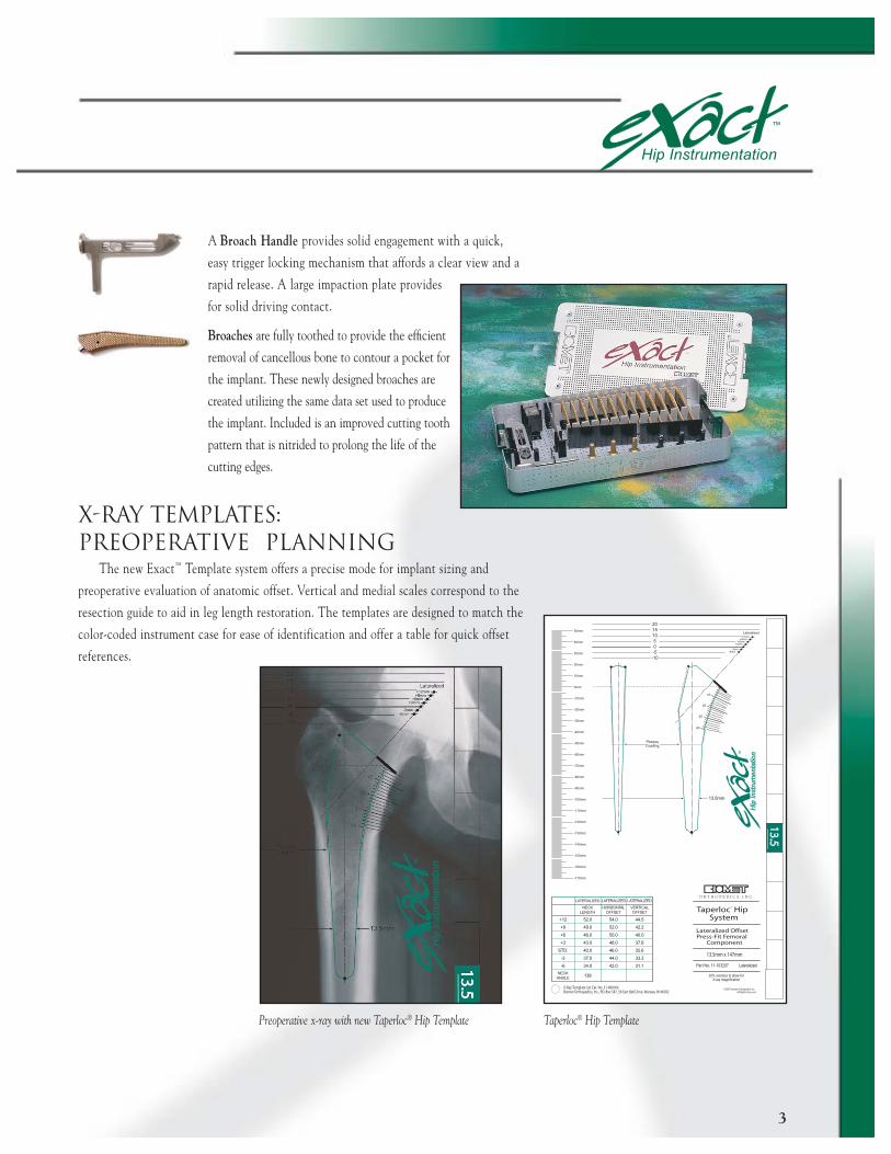
X-RAY TEMPLATES: PREOPERATIVE PLANNING
The new Exact™ Template system offers a precise mode for implant sizing and
preoperative evaluation of anatomic offset. Vertical and medial scales correspond to the
resection guide to aid in leg length restoration. The templates are designed to match the
color-coded instrument case for ease of identification and offer a table for quick offset
references.
Taperloc® Hip Template
3
Preoperative x-ray with new Taperloc® Hip Template
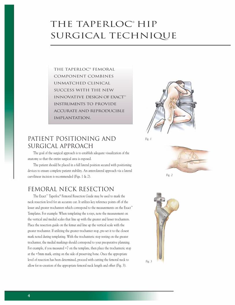
PATIENT POSITIONING AND SURGICAL APPROACH
The goal of the surgical approach is to establish adequate visualization of the
anatomy so that the entire surgical area is exposed.
The patient should be placed in a full lateral position secured with positioning
devices to ensure complete patient stability. An anterolateral approach via a lateral
curvilinear incision is recommended (Figs. 1 & 2).
FEMORAL NECK RESECTIONThe Exact™ Taperloc® Femoral Resection Guide may be used to mark the
neck resection level for an accurate cut. It utilizes key reference points off of the
lesser and greater trochanters which correspond to the measurements on the Exact™
Templates. For example: When templating the x-rays, note the measurement on
the vertical and medial scales that line up with the greater and lesser trochanters.
Place the resection guide on the femur and line up the vertical scale with the
greater trochanter. If utilizing the greater trochanter stop, pre-set it to the closest
mark noted during templating. With the trochanteric stop resting on the greater
trochanter, the medial markings should correspond to your preoperative planning.
For example, if you measured +7 on the template, then place the trochanteric stop
at the +5mm mark, erring on the side of preserving bone. Once the appropriate
level of resection has been determined, proceed with cutting the femoral neck to
allow for re-creation of the appropriate femoral neck length and offset (Fig. 3).
the taperloc® femoral
component combines
unmatched clinical
success with the new
innovative design of exact™
instruments to provide
accurate and reproducible
implantation.
Fig. 1
Fig. 3
the taperloc® hip surgical technique
4
Fig. 2
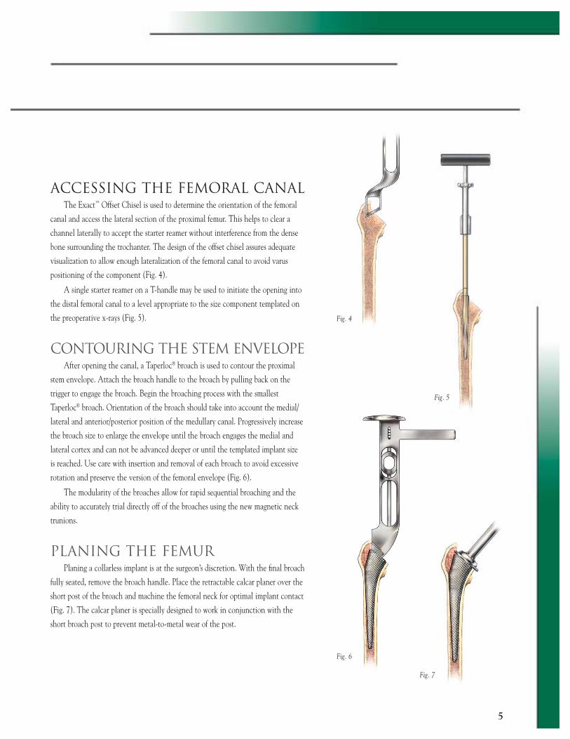
ACCESSING THE FEMORAL CANALThe Exact™ Offset Chisel is used to determine the orientation of the femoral
canal and access the lateral section of the proximal femur. This helps to clear a
channel laterally to accept the starter reamer without interference from the dense
bone surrounding the trochanter. The design of the offset chisel assures adequate
visualization to allow enough lateralization of the femoral canal to avoid varus
positioning of the component (Fig. 4).
A single starter reamer on a T-handle may be used to initiate the opening into
the distal femoral canal to a level appropriate to the size component templated on
the preoperative x-rays (Fig. 5).
CONTOURING THE STEM ENVELOPEAfter opening the canal, a Taperloc® broach is used to contour the proximal
stem envelope. Attach the broach handle to the broach by pulling back on the
trigger to engage the broach. Begin the broaching process with the smallest
Taperloc® broach. Orientation of the broach should take into account the medial/
lateral and anterior/posterior position of the medullary canal. Progressively increase
the broach size to enlarge the envelope until the broach engages the medial and
lateral cortex and can not be advanced deeper or until the templated implant size
is reached. Use care with insertion and removal of each broach to avoid excessive
rotation and preserve the version of the femoral envelope (Fig. 6).
The modularity of the broaches allow for rapid sequential broaching and the
ability to accurately trial directly off of the broaches using the new magnetic neck
trunions.
PLANING THE FEMURPlaning a collarless implant is at the surgeon’s discretion. With the fi nal broach
fully seated, remove the broach handle. Place the retractable calcar planer over the
short post of the broach and machine the femoral neck for optimal implant contact
(Fig. 7). The calcar planer is specially designed to work in conjunction with the
short broach post to prevent metal-to-metal wear of the post.
Fig. 6
5
Fig. 7
Fig. 4
Fig. 5
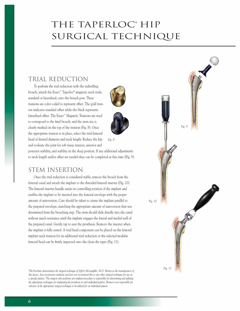
Fig. 11
TRIAL REDUCTIONTo perform the trial reduction with the indwelling
broach, attach the Exact™ Taperloc® magnetic neck trials,
standard or lateralized, onto the broach post. These
trunions are color coded to represent offset. The gold trun-
ion indicates standard offset while the black represents
lateralized offset. The Exact™ Magnetic Trunions are sized
to correspond to the fi nal broach, and the stem size is
clearly marked on the top of the trunion (Fig. 8). Once
the appropriate trunion is in place, select the trial femoral
head of desired diameter and neck length. Reduce the hip
and evaluate the joint for soft tissue tension, anterior and
posterior stability, and stability in the sleep position. If any additional adjustments
to neck length and/or offset are needed they can be completed at this time (Fig. 9).
STEM INSERTIONOnce the trial reduction is considered stable, remove the broach from the
femoral canal and attach the implant to the threaded femoral inserter (Fig. 10).
The femoral inserter handle assists in controlling rotation of the implant and
enables the implant to be inserted into the femoral envelope with the proper
amount of anteversion. Care should be taken to orient the implant parallel to
the prepared envelope, matching the appropriate amount of anteversion that was
determined from the broaching step. The stem should slide distally into the canal
without much resistance until the implant engages the lateral and medial wall of
the prepared canal. Gently tap to seat the prosthesis. Remove the inserter when
the implant is fully seated. A trial head component can be placed on the femoral
implant neck trunion for an additional trial reduction or the selected modular
femoral head can be fi rmly impacted onto the clean dry taper (Fig. 11).
Fig. 10
the taperloc® hip surgical technique
Fig. 9
Fig. 8
6
This brochure demonstrates the surgical technique of Jeffery McLaughlin, M.D. Biomet as the manufacturer of this device, does not practice medicine and does not recommend this or any other surgical technique for use on a specifi c patient. The surgeon who performs any implant procedure is responsible for determining and utilizing the appropriate techniques for implanting the prosthesis in each individual patient. Biomet is not responsible for selection of the appropriate surgical technique to be utilized for an individual patient.
7
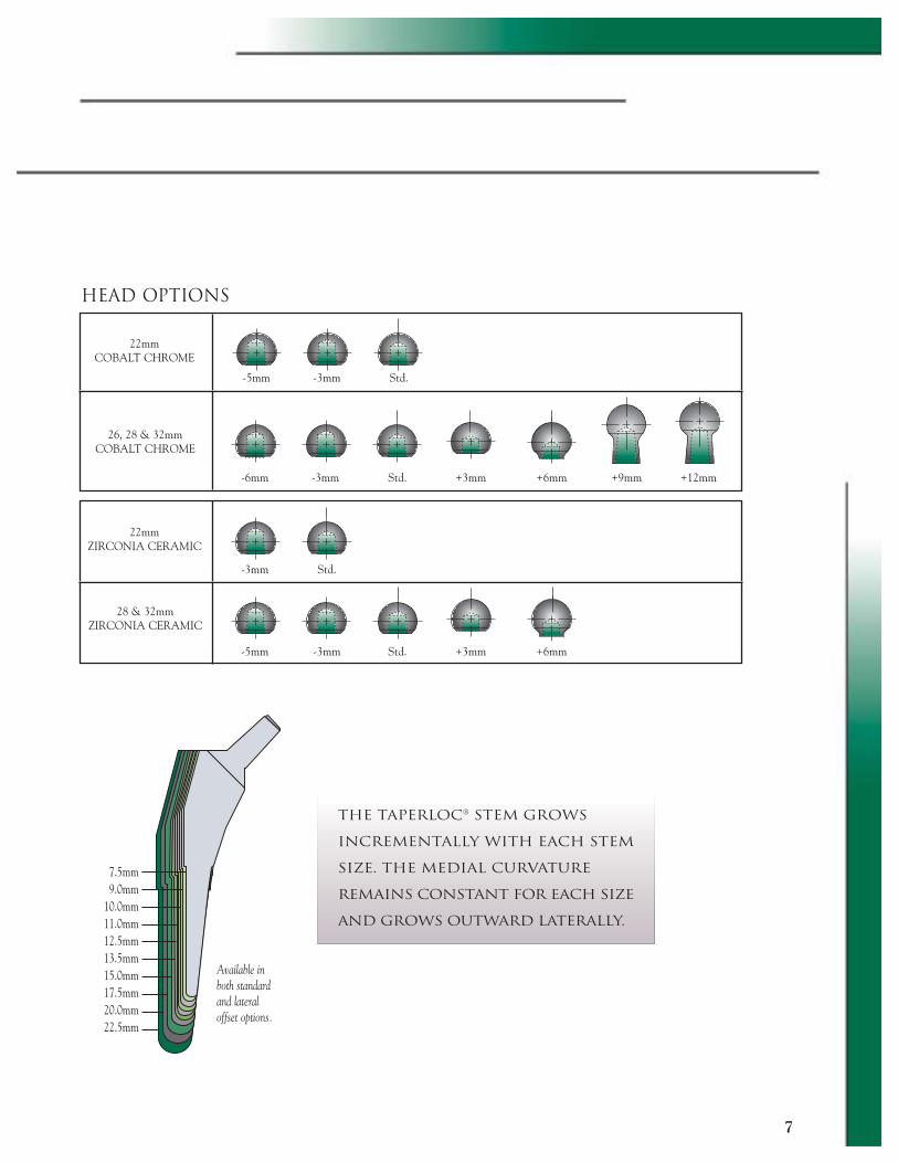
HEAD OPTIONS
-5mm -3mm Std.
-6mm -3mm Std. +3mm +6mm +9mm +12mm
-3mm Std.
-5mm -3mm Std. +3mm +6mm
Available in both standard and lateral offset options.
7.5mm9.0mm
10.0mm11.0mm12.5mm13.5mm15.0mm17.5mm20.0mm22.5mm
the taperloc® stem grows
incrementally with each stem
size. The medial curvature
remains constant for each size
and grows outward laterally.
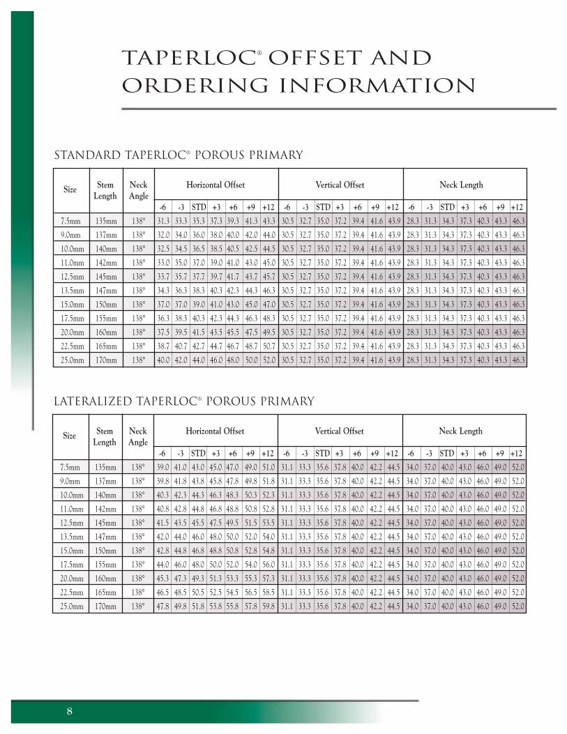
taperloc® offset and ordering information
STANDARD TAPERLOC® POROUS PRIMARY
8
LATERALIZED TAPERLOC® POROUS PRIMARY
Size Stem Neck Horizontal Offset Vertical Offset Neck Length Length Angle
-6 -3 STD +3 +6 +9 +12 -6 -3 STD +3 +6 +9 +12 -6 -3 STD +3 +6 +9 +12
7.5mm 135mm 138° 39.0 41.0 43.0 45.0 47.0 49.0 51.0 31.1 33.3 35.6 37.8 40.0 42.2 44.5 34.0 37.0 40.0 43.0 46.0 49.0 52.0
9.0mm 137mm 138° 39.8 41.8 43.8 45.8 47.8 49.8 51.8 31.1 33.3 35.6 37.8 40.0 42.2 44.5 34.0 37.0 40.0 43.0 46.0 49.0 52.0
10.0mm 140mm 138° 40.3 42.3 44.3 46.3 48.3 50.3 52.3 31.1 33.3 35.6 37.8 40.0 42.2 44.5 34.0 37.0 40.0 43.0 46.0 49.0 52.0
11.0mm 142mm 138° 40.8 42.8 44.8 46.8 48.8 50.8 52.8 31.1 33.3 35.6 37.8 40.0 42.2 44.5 34.0 37.0 40.0 43.0 46.0 49.0 52.0
12.5mm 145mm 138° 41.5 43.5 45.5 47.5 49.5 51.5 53.5 31.1 33.3 35.6 37.8 40.0 42.2 44.5 34.0 37.0 40.0 43.0 46.0 49.0 52.0
13.5mm 147mm 138° 42.0 44.0 46.0 48.0 50.0 52.0 54.0 31.1 33.3 35.6 37.8 40.0 42.2 44.5 34.0 37.0 40.0 43.0 46.0 49.0 52.0
15.0mm 150mm 138° 42.8 44.8 46.8 48.8 50.8 52.8 54.8 31.1 33.3 35.6 37.8 40.0 42.2 44.5 34.0 37.0 40.0 43.0 46.0 49.0 52.0
17.5mm 155mm 138° 44.0 46.0 48.0 50.0 52.0 54.0 56.0 31.1 33.3 35.6 37.8 40.0 42.2 44.5 34.0 37.0 40.0 43.0 46.0 49.0 52.0
20.0mm 160mm 138° 45.3 47.3 49.3 51.3 53.3 55.3 57.3 31.1 33.3 35.6 37.8 40.0 42.2 44.5 34.0 37.0 40.0 43.0 46.0 49.0 52.0
22.5mm 165mm 138° 46.5 48.5 50.5 52.5 54.5 56.5 58.5 31.1 33.3 35.6 37.8 40.0 42.2 44.5 34.0 37.0 40.0 43.0 46.0 49.0 52.0
25.0mm 170mm 138° 47.8 49.8 51.8 53.8 55.8 57.8 59.8 31.1 33.3 35.6 37.8 40.0 42.2 44.5 34.0 37.0 40.0 43.0 46.0 49.0 52.0
Size Stem Neck Horizontal Offset Vertical Offset Neck Length Length Angle
-6 -3 STD +3 +6 +9 +12 -6 -3 STD +3 +6 +9 +12 -6 -3 STD +3 +6 +9 +12
7.5mm 135mm 138° 31.3 33.3 35.3 37.3 39.3 41.3 43.3 30.5 32.7 35.0 37.2 39.4 41.6 43.9 28.3 31.3 34.3 37.3 40.3 43.3 46.3
9.0mm 137mm 138° 32.0 34.0 36.0 38.0 40.0 42.0 44.0 30.5 32.7 35.0 37.2 39.4 41.6 43.9 28.3 31.3 34.3 37.3 40.3 43.3 46.3
10.0mm 140mm 138° 32.5 34.5 36.5 38.5 40.5 42.5 44.5 30.5 32.7 35.0 37.2 39.4 41.6 43.9 28.3 31.3 34.3 37.3 40.3 43.3 46.3
11.0mm 142mm 138° 33.0 35.0 37.0 39.0 41.0 43.0 45.0 30.5 32.7 35.0 37.2 39.4 41.6 43.9 28.3 31.3 34.3 37.3 40.3 43.3 46.3
12.5mm 145mm 138° 33.7 35.7 37.7 39.7 41.7 43.7 45.7 30.5 32.7 35.0 37.2 39.4 41.6 43.9 28.3 31.3 34.3 37.3 40.3 43.3 46.3
13.5mm 147mm 138° 34.3 36.3 38.3 40.3 42.3 44.3 46.3 30.5 32.7 35.0 37.2 39.4 41.6 43.9 28.3 31.3 34.3 37.3 40.3 43.3 46.3
15.0mm 150mm 138° 37.0 37.0 39.0 41.0 43.0 45.0 47.0 30.5 32.7 35.0 37.2 39.4 41.6 43.9 28.3 31.3 34.3 37.3 40.3 43.3 46.3
17.5mm 155mm 138° 36.3 38.3 40.3 42.3 44.3 46.3 48.3 30.5 32.7 35.0 37.2 39.4 41.6 43.9 28.3 31.3 34.3 37.3 40.3 43.3 46.3
20.0mm 160mm 138° 37.5 39.5 41.5 43.5 45.5 47.5 49.5 30.5 32.7 35.0 37.2 39.4 41.6 43.9 28.3 31.3 34.3 37.3 40.3 43.3 46.3
22.5mm 165mm 138° 38.7 40.7 42.7 44.7 46.7 48.7 50.7 30.5 32.7 35.0 37.2 39.4 41.6 43.9 28.3 31.3 34.3 37.3 40.3 43.3 46.3
25.0mm 170mm 138° 40.0 42.0 44.0 46.0 48.0 50.0 52.0 30.5 32.7 35.0 37.2 39.4 41.6 43.9 28.3 31.3 34.3 37.3 40.3 43.3 46.3
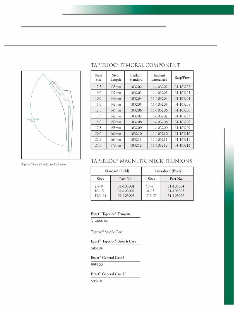
TAPERLOC® FEMORAL COMPONENT
Exact™ Taperloc® Template
31-400164
Taperloc® Specifi c Cases:
Exact™ Taperloc® Broach Case
595104
Exact™ General Case I
595100
Exact™ General Case II
595101
TAPERLOC® MAGNETIC NECK TRUNIONS
Standard (Gold) Lateralized (Black) Sizes Part No. Sizes Part No.
7.5–9 31-103001 7.5–9 31-103004 10–15 31-103002 10–15 31-103005 17.5–25 31-103003 17.5–25 31-103006
Neck Angle138.0°
Taperloc® Standard and Lateralized Stems
Stem Stem Implant Implant Rasp/Prov. Size Length Standard Lateralized
7.5 135mm 103202 11-103202 31-103202
9.0 137mm 103203 11-103203 31-103203
10.0 140mm 103204 11-103204 31-103204
11.0 142mm 103205 11-103205 31-103205
12.5 145mm 103206 11-103206 31-103206
13.5 147mm 103207 11-103207 31-103207
15.0 150mm 103208 11-103208 31-103208
17.5 155mm 103209 11-103209 31-103209
20.0 160mm 103210 11-103210 31-103210
22.5 165mm 103211 11-103211 31-103211
25.0 170mm 103212 11-103212 31-103212

P.O. Box 587, Warsaw, IN 46581-0587 • 574.267.6639 • ©2002 Biomet Orthopedics, Inc. All Rights Reservedweb site: www.biomet.com • eMail: [email protected]
Form No. Y-BMT-745/022802/K
REFERENCES
1. Bourne, R.B.; et al.: “Ingrowth Surfaces: Plasma Spray Coating to Titanium Alloy Hip Replacements.” Clin. Orthop., 298: 37–46, 1994.
2. Collier, J.P.; Head, W.C.; Koeneman, J.; et al.: Symposium: “Porous Coating Methods: The Pros and Cons.” Contemporary Orthop., 27(3): 269–296, 1993.
3. Emerson, R.H.; Sanders, R.B.; Head, W.C.; Higgins, L.: “Effect of Circumferential Plasma-spray Porous Coating on the Rate of Femoral Osteolysis After Total Hip Arthroplasty.” J. Bone Joint Surg., 81-A: 1291–8, Sept. 1990.
4. Head, W.C.: “Mallory-Head Porous Press-Fit Primary Hip Replacement.” Presented at the Tenth Annual International Symposium: New Developments in Total Joint Reconstruction, Lake Tahoe, Nevada, June 14–16, 1993.
5. Hozack, W.; Rothman, R.; Eng, K.; Mesa, J.: “Primary Cementless Hip Arthroplasty with a Titanium Plasma Sprayed Prosthesis.” CORR, 33(3): 217–225, Dec. 1996.
6. Hozack, W.: “Ten Year Experience with a Wedge-Fit Stem.” Crucial Decisions in Total Joint Replacement and Sports Medicine, Bermuda, 1998.
7. Keisu, Kjell; Orozco, F.; Sharkey, P.; et al.:“Primary Cementless Total Hip Arthroplasty inOctogenarians: Two to Eleven Year Follow-up.” J. Bone Joint Surg., 83-A: 359–363, 2001.
8. Leudeman, R.: “The Effect of a Plasma Sprayed Porous Ti-Alloy Coating on the Rotation Beam Fatigue Strength of Co-Cr-Mo Alloy.” Biomet Technical Report, 1994.
9. McLaughlin, J.R.; Lee, K.R.: “Total Hip Arthroplasty with an Uncemented Femoral Component.” J. Bone Joint Surg., 79-B: 900–907, 1997.
10. McLaughlin, J.R.: “Plasma Sprayed Porous-Coated Total Hip Arthroplasty: A 13-year Survivorship Analysis in Patients Age 50+ and Under.” Presented at the 63rd AAOS, San Francisco, 1997.
11. Sharkey, P.F.; et al.: “Initial Stability of a Collarless Wedge-Shaped Prosthesis in the Femoral Canal.” Seminars in Arthroplasty, 1(1): 87–90, July 1990.
12. Symposium: “Porous Coating Methods: The Pros and Cons.” Contemporary Orthop., 27(3): 469–296, Sept. 1993.
13. Tanzer, M.; et al.: “The Progression of Femoral Cortical Osteolysis in Association with Total Hip Arthroplasty without Cements.” J. Bone Joint Surg., 74-A: March, 1992.
Taperloc® is a registered trademark of Biomet, Inc.Exact™ is a trademark of Biomet, Inc.


![gains --Engh•h prot erb - Southington Library & Museumsouthingtonlibrary.org/PDFFiles/newspapers/1984/08_2_1984.pdf · onor of the Order. Delletier, ... reported 2.1584] more oc-curences](https://static.fdocuments.net/doc/165x107/5ac759947f8b9a5c558e9c40/gains-enghh-prot-erb-southington-library-muse-of-the-order-delletier-.jpg)