Tantalum Surface Mount Capacitors – Low ESR T495 …€¦ · Tantalum Surface Mount Capacitors...
28
© KEMET Electronics Corporation • P.O. Box 5928 • Greenville, SC 29606 • 864-963-6300 • www.kemet.com T2009_T495 • 3/20/2018 1 One world. One KEMET Benefits • Meets or exceeds EIA Standard 535BAAC • Taped and reeled per EIA 481 • High surge current capability • Optional gold-plated terminations • High ripple current capability • 100% surge current test on B, C, D, E, U, V, and X sizes • 100% steady-state accelerated aging • Capacitance values of 0.1 to 1,000 μF • Tolerances of ±10% and ±20% • Voltage rating of 2.5 – 50 VDC • Extended range values • RoHS compliant and lead-free terminations • Operating temperature range of −55°C to +125°C Overview The low ESR, surge-robust T495 is designed for demanding applications that require high surge current and high ripple current capability. The T495 builds upon the proven capabilities of our industrial grade tantalum chip capacitors to offer several advantages such as low ESR, high ripple current capability, excellent capacitance stability, and improved resistance to high in-rush currents. These benefits are achieved through a combination of proprietary design, materials, and process parameters, as well as high-stress, low impedance electrical conditioning performed prior to screening.The T495 is classified as moisture sensitivity level (MSL) 1 under J STD 020, with unlimited floorlife time at ≤ 30°C/85% RH. Tantalum Surface Mount Capacitors – Low ESR T495 Surge Robust MnO 2 Applications Typical applications include decoupling and filtering in automotive end applications, such as DC/DC converters, portable electronics, telecommunications, and control units requiring high ripple current capability. Environmental Compliance RoHS compliant (6/6) according to Directive 2002/95/EC when ordered with 100% Sn solder, Gold-plated or Non-magnetic 100% Sn solder.
Transcript of Tantalum Surface Mount Capacitors – Low ESR T495 …€¦ · Tantalum Surface Mount Capacitors...
© KEMET Electronics Corporation • P.O. Box 5928 • Greenville, SC 29606 • 864-963-6300 • www.kemet.com T2009_T495 • 3/20/2018 1One world. One KEMET
Benefits
• Meets or exceeds EIA Standard 535BAAC• Taped and reeled per EIA 481• High surge current capability• Optional gold-plated terminations• High ripple current capability• 100% surge current test on B, C, D, E, U, V, and X sizes• 100% steady-state accelerated aging• Capacitancevaluesof0.1to1,000μF• Tolerances of ±10% and ±20%• Voltage rating of 2.5 – 50 VDC• Extended range values• RoHS compliant and lead-free terminations• Operatingtemperaturerangeof−55°Cto+125°C
Overview
The low ESR, surge-robust T495 is designed for demanding applications that require high surge current and high ripple current capability. The T495 builds upon the proven capabilities of our industrial grade tantalum chip capacitors to offer several advantages such as low ESR, high ripple current capability, excellent capacitance stability, and improved resistance to high in-rush currents.
Thesebenefitsareachievedthroughacombinationofproprietary design, materials, and process parameters, as well as high-stress, low impedance electrical conditioning performedpriortoscreening.TheT495isclassifiedasmoisture sensitivity level (MSL) 1 under J STD 020, with unlimitedfloorlifetimeat≤30°C/85%RH.
Tantalum Surface Mount Capacitors – Low ESR
T495 Surge Robust MnO2
Applications
Typicalapplicationsincludedecouplingandfilteringinautomotiveendapplications,suchasDC/DCconverters,portableelectronics, telecommunications, and control units requiring high ripple current capability.
Environmental Compliance
RoHS compliant (6/6) according to Directive 2002/95/EC when ordered with 100% Sn solder, Gold-plated or Non-magnetic 100% Sn solder.
© KEMET Electronics Corporation • P.O. Box 5928 • Greenville, SC 29606 • 864-963-6300 • www.kemet.com T2009_T495 • 3/20/2018 22
Tantalum Surface Mount Capacitors – Low ESRT495 Surge Robust MnO2
K-SIM
Foradetailedanalysisofspecificpartnumbers,pleasevisitksim.kemet.comtoaccessKEMET’sK-SIMsoftware.KEMETK-SIM is designed to simulate behavior of components with respect to frequency, ambient temperature, and DC bias levels.
Ordering Information
T 495 X 107 M 010 A T E045Capacitor
Class Series Case Size
Capacitance Code(pF)
Capacitance Tolerance
Rated Voltage (VDC)
FailureRate/Design TerminationFinish ESR Packaging
(C-Spec)
T = Tantalum
Surge Robust
Low ESR
A, B, C, D, E, M, T, U, V, W, X
Firsttwodigits
represent significant
figures.Thirddigitspecifies
number of zeros.
K = ±10%M = ±20%
2R5 = 2.5 004 = 4 006 = 6.3 010 = 10 016 = 16 020 = 20 025 = 25 035 = 35 050 = 50
A = N/A T = 100% Matte tin (Sn)-platedH = Standard solder coated (SnPb 5% Pb minimum)G = Gold-plated (A, B, C, D, X only)N = Non-magnetic 100% tin (Sn)M = Non-magnetic (SnPb)
E = ESRlast three
digits specify ESRinmΩ
(45=45mΩ)
Blank = 7" reel7280 = 13" reel
Performance Characteristics
Item Performance CharacteristicsOperating Temperature −55°Cto125°C
Rated Capacitance Range 0.47–1,000µFat120Hz/25°C
Capacitance Tolerance K tolerance (10%), M tolerance (20%)
Rated Voltage Range 2.5 – 50 V
DF(120Hz) RefertoPartNumberElectricalSpecificationTable
ESR (100 kHz) RefertoPartNumberElectricalSpecificationTable
Leakage Current ≤0.01CV(µA)atratedvoltageafter5minutes
© KEMET Electronics Corporation • P.O. Box 5928 • Greenville, SC 29606 • 864-963-6300 • www.kemet.com T2009_T495 • 3/20/2018 33
Tantalum Surface Mount Capacitors – Low ESRT495 Surge Robust MnO2
Qualification
Test Condition Characteristics
Endurance 85°Catratedvoltage,2,000hours.125°Cat2/3ratedvoltage,2,000hours.
ΔC/C Within ±10% of initial value
DF Within initial limits
DCL Within 1.25 x initial limit
ESR Within initial limits
Storage Life 125°Cat0volts,2,000hours.
ΔC/C Within ±10% of initial value
DF Within initial limits
DCL Within 1.25 x initial limit
ESR Within initial limits
Thermal Shock MIL–STD–202, Method 107, Condition B, mounted, −55C°to125°C,1,000cycles.
ΔC/C Within ±5% of initial value
DF Within initial limits
DCL Within 1.25 x initial limit
ESR Within initial limits
Temperature StabilityExtreme temperature exposure at a successionofcontinuousstepsat+25°C,−55°C,+25°C,+85°C,+125°C,+25°C.
+25°C −55°C +85°C +125°C
ΔC/C IL* ±10% ±10% ±20%
DF IL IL 1.5 x IL 1.5 x IL
DCL IL N/A 10 x IL 12 x IL
Surge Voltage 85°C,1.32xratedvoltage1,000cycles(125°C,1.2xratedvoltage).
ΔC/C Within ±5% of initial value
DF Within initial limits
DCL Within initial limits
ESR Within initial limits
Mechanical Shock/Vibration
MIL–STD–202, Method 213, Condition I, 100 G peakMIL–STD–202, Method 204, Condition D, 10 Hz to 2,000 Hz, 20 G peak
ΔC/C Within ±10% of initial value
DF Within initial limits
DCL Within initial limits
*IL = Initial limit
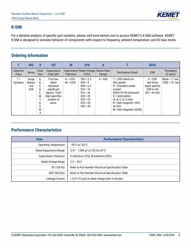
Electrical Characteristics
1
10
100
1,000
100 1,000 10,000 100,000 1,000,000 10,000,000
Capa
cita
nce
(μF)
Frequency (Hz)
T495C476M016ATE350
T495D157M016ATE085
T495X227M016ATE100
Capacitancevs.Frequency
0.01
0.1
1
10
100
100 1,000 10,000 100,000 1,000,000 10,000,000
Impe
danc
e, E
SR (O
hms)
Frequency (Hz)
T495C476M016ATE350_IMP
T495D157M016ATE085_IMP
T495X227M016ATE100_IMP
T495C476M016ATE350_ESR
T495D157M016ATE085_ESR
T495X227M016ATE100_ESR
ESRvs.Frequency
© KEMET Electronics Corporation • P.O. Box 5928 • Greenville, SC 29606 • 864-963-6300 • www.kemet.com T2009_T495 • 3/20/2018 44
Tantalum Surface Mount Capacitors – Low ESRT495 Surge Robust MnO2
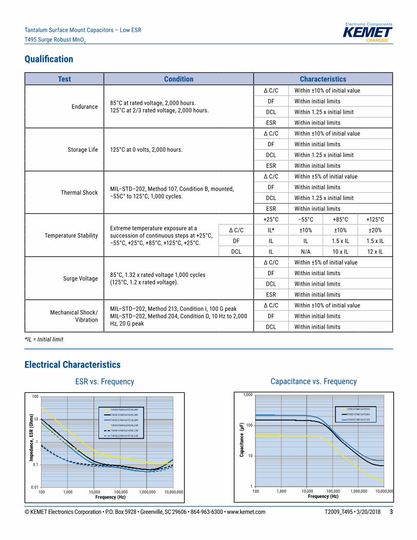
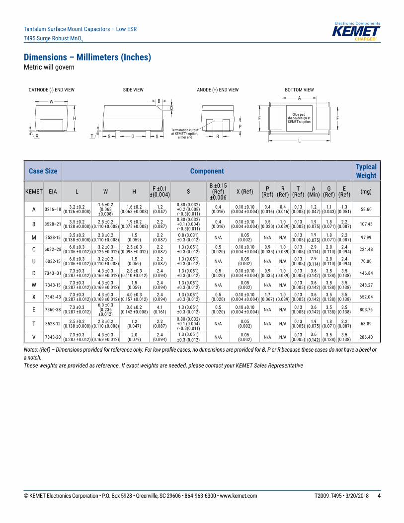
Dimensions – Millimeters (Inches)Metric will govern
H
X T
B B
G
F E
A
L R
P
SIDE VIEW ANODE (+) END VIEW BOTTOM VIEWCATHODE (-) END VIEW
W
S STermination cutout at KEMET's option,
either end
Glue pad shape/design at KEMET's option
Case Size Component Typical Weight
KEMET EIA L W H F±0.1±(0.004) S
B ±0.15 (Ref)
±0.006X (Ref) P
(Ref)R
(Ref)T
(Ref)A
(Min)G
(Ref)E
(Ref) (mg)
A 3216–18 3.2 ±0.2 (0.126 ±0.008)
1.6 ±0.2 (0.063
±0.008)1.6 ±0.2
(0.063 ±0.008)1.2
(0.047)0.80 (0.032) +0.2(0.008) /−0.3(0.011)
0.4 (0.016)
0.10 ±0.10 (0.004 ±0.004)
0.4 (0.016)
0.4 (0.016)
0.13 (0.005)
1.2 (0.047)
1.1 (0.043)
1.3 (0.051) 58.60
B 3528–21 3.5 ±0.2 (0.138 ±0.008)
2.8 ±0.2 (0.110 ±0.008)
1.9 ±0.2(0.075 ±0.008)
2.2 (0.087)
0.80 (0.032) +0.1(0.004) /−0.3(0.011)
0.4 (0.016)
0.10 ±0.10 (0.004 ±0.004)
0.5 (0.020)
1.0 (0.039)
0.13 (0.005)
1.9 (0.075)
1.8 (0.071)
2.2 (0.087) 107.45
M 3528-15 3.5 ±0.2 (0.138 ±0.008)
2.8 ±0.2 (0.110 ±0.008)
1.5 (0.059)
2.2 (0.087)
0.8 (0.031) ±0.3 (0.012) N/A 0.05
(0.002) N/A N/A 0.13 (0.005)
1.9 (0.075)
1.8 (0.071)
2.2 (0.087) 97.99
C 6032–28 6.0 ±0.3 (0.236 ±0.012)
3.2 ±0.3 (0.126 ±0.012)
2.5 ±0.3 (0.098 ±0.012)
2.2 (0.087)
1.3 (0.051) ±0.3 (0.012)
0.5 (0.020)
0.10 ±0.10 (0.004 ±0.004)
0.9 (0.035)
1.0 (0.039)
0.13 (0.005)
2.9 (0.114)
2.8 (0.110)
2.4 (0.094) 224.48
U 6032-15 6.0 ±0.3 (0.236 ±0.012)
3.2 ±0.2 (0.110 ±0.008)
1.5 (0.059)
2.2 (0.087)
1.3 (0.051) ±0.3 (0.012) N/A 0.05
(0.002) N/A N/A 0.13 (0.005)
2.9 (0.114)
2.8 (0.110)
2.4 (0.094) 70.00
D 7343–31 7.3 ±0.3 (0.287 ±0.012)
4.3 ±0.3 (0.169 ±0.012)
2.8 ±0.3(0.110 ±0.012)
2.4 (0.094)
1.3 (0.051) ±0.3 (0.012)
0.5 (0.020)
0.10 ±0.10 (0.004 ±0.004)
0.9 (0.035)
1.0 (0.039)
0.13 (0.005)
3.6 (0.142)
3.5 (0.138)
3.5 (0.138) 446.84
W 7343-15 7.3 ±0.3 (0.287 ±0.012)
4.3 ±0.3 (0.169 ±0.012)
1.5 (0.059)
2.4 (0.094)
1.3 (0.051) ±0.3 (0.012) N/A 0.05
(0.002) N/A N/A 0.13 (0.005)
3.6 (0.142)
3.5 (0.138)
3.5 (0.138) 248.27
X 7343-43 7.3 ±0.3 (0.287 ±0.012)
4.3 ±0.3 (0.169 ±0.012)
4.0 ±0.3 (0.157 ±0.012)
2.4 (0.094)
1.3 (0.051) ±0.3 (0.012)
0.5 (0.020)
0.10 ±0.10 (0.004 ±0.004)
1.7 (0.067)
1.0 (0.039)
0.13 (0.005)
3.6 (0.142)
3.5 (0.138)
3.5 (0.138) 652.04
E 7360-38 7.3 ±0.3 (0.287 ±0.012)
6.0 ±0.3 (0.236 ±0.012)
3.6 ±0.2 (0.142 ±0.008)
4.1 (0.161)
1.3 (0.051) ±0.3 (0.012)
0.5 (0.020)
0.10 ±0.10 (0.004 ±0.004) N/A N/A 0.13
(0.005)3.6
(0.142)3.5
(0.138)3.5
(0.138) 803.76
T 3528-12 3.5 ±0.2 (0.138 ±0.008)
2.8 ±0.2 (0.110 ±0.008)
1.2 (0.047)
2.2 (0.087)
0.80 (0.032) +0.1(0.004) /−0.3(0.011)
N/A 0.05 (0.002) N/A N/A 0.13
(0.005)1.9
(0.075)1.8
(0.071)2.2
(0.087) 63.89
V 7343-20 7.3 ±0.3 (0.287 ±0.012)
4.3 ±0.3 (0.169 ±0.012)
2.0 (0.079)
2.4 (0.094)
1.3 (0.051) ±0.3 (0.012) N/A 0.05
(0.002) N/A N/A 0.13 (0.005)
3.6 (0.142)
3.5 (0.138)
3.5 (0.138) 286.40
Notes: (Ref) – Dimensions provided for reference only. For low profile cases, no dimensions are provided for B, P or R because these cases do not have a bevel or a notch.These weights are provided as reference. If exact weights are needed, please contact your KEMET Sales Representative
© KEMET Electronics Corporation • P.O. Box 5928 • Greenville, SC 29606 • 864-963-6300 • www.kemet.com T2009_T495 • 3/20/2018 55
Tantalum Surface Mount Capacitors – Low ESRT495 Surge Robust MnO2
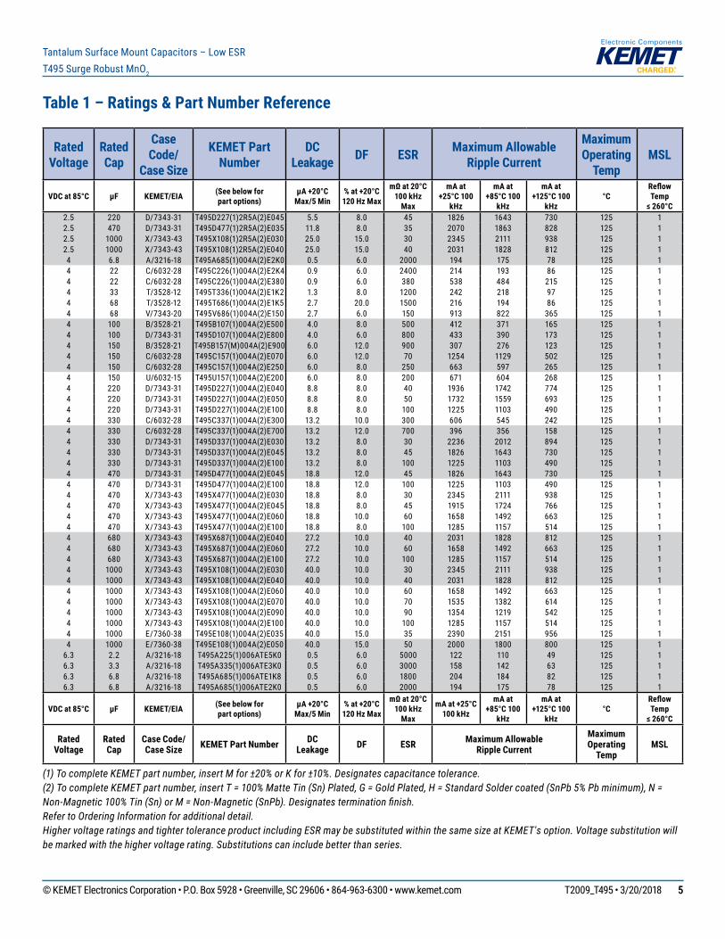
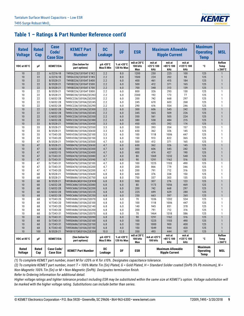
Table 1 – Ratings & Part Number Reference
(1) To complete KEMET part number, insert M for ±20% or K for ±10%. Designates capacitance tolerance.(2) To complete KEMET part number, insert T = 100% Matte Tin (Sn) Plated, G = Gold Plated, H = Standard Solder coated (SnPb 5% Pb minimum), N = Non-Magnetic 100% Tin (Sn) or M = Non-Magnetic (SnPb). Designates termination finish.Refer to Ordering Information for additional detail.Higher voltage ratings and tighter tolerance product including ESR may be substituted within the same size at KEMET's option. Voltage substitution will be marked with the higher voltage rating. Substitutions can include better than series.
Rated Voltage
Rated Cap
Case Code/
Case Size
KEMET Part Number
DC Leakage DF ESR Maximum Allowable
Ripple Current
Maximum Operating
TempMSL
VDC at 85°C µF KEMET/EIA (See below forpart options)
µA +20°CMax/5 Min
% at +20°C120 Hz Max
mΩ at 20°C100 kHz
Max
mA at +25°C 100
kHz
mA at +85°C 100
kHz
mA at +125°C 100
kHz °C
Reflow Temp
≤ 260°C2.5 220 D/7343-31 T495D227(1)2R5A(2)E045 5.5 8.0 45 1826 1643 730 125 12.5 470 D/7343-31 T495D477(1)2R5A(2)E035 11.8 8.0 35 2070 1863 828 125 12.5 1000 X/7343-43 T495X108(1)2R5A(2)E030 25.0 15.0 30 2345 2111 938 125 12.5 1000 X/7343-43 T495X108(1)2R5A(2)E040 25.0 15.0 40 2031 1828 812 125 14 6.8 A/3216-18 T495A685(1)004A(2)E2K0 0.5 6.0 2000 194 175 78 125 14 22 C/6032-28 T495C226(1)004A(2)E2K4 0.9 6.0 2400 214 193 86 125 14 22 C/6032-28 T495C226(1)004A(2)E380 0.9 6.0 380 538 484 215 125 14 33 T/3528-12 T495T336(1)004A(2)E1K2 1.3 8.0 1200 242 218 97 125 14 68 T/3528-12 T495T686(1)004A(2)E1K5 2.7 20.0 1500 216 194 86 125 14 68 V/7343-20 T495V686(1)004A(2)E150 2.7 6.0 150 913 822 365 125 14 100 B/3528-21 T495B107(1)004A(2)E500 4.0 8.0 500 412 371 165 125 14 100 D/7343-31 T495D107(1)004A(2)E800 4.0 6.0 800 433 390 173 125 14 150 B/3528-21 T495B157(M)004A(2)E900 6.0 12.0 900 307 276 123 125 14 150 C/6032-28 T495C157(1)004A(2)E070 6.0 12.0 70 1254 1129 502 125 14 150 C/6032-28 T495C157(1)004A(2)E250 6.0 8.0 250 663 597 265 125 14 150 U/6032-15 T495U157(1)004A(2)E200 6.0 8.0 200 671 604 268 125 14 220 D/7343-31 T495D227(1)004A(2)E040 8.8 8.0 40 1936 1742 774 125 14 220 D/7343-31 T495D227(1)004A(2)E050 8.8 8.0 50 1732 1559 693 125 14 220 D/7343-31 T495D227(1)004A(2)E100 8.8 8.0 100 1225 1103 490 125 14 330 C/6032-28 T495C337(1)004A(2)E300 13.2 10.0 300 606 545 242 125 14 330 C/6032-28 T495C337(1)004A(2)E700 13.2 12.0 700 396 356 158 125 14 330 D/7343-31 T495D337(1)004A(2)E030 13.2 8.0 30 2236 2012 894 125 14 330 D/7343-31 T495D337(1)004A(2)E045 13.2 8.0 45 1826 1643 730 125 14 330 D/7343-31 T495D337(1)004A(2)E100 13.2 8.0 100 1225 1103 490 125 14 470 D/7343-31 T495D477(1)004A(2)E045 18.8 12.0 45 1826 1643 730 125 14 470 D/7343-31 T495D477(1)004A(2)E100 18.8 12.0 100 1225 1103 490 125 14 470 X/7343-43 T495X477(1)004A(2)E030 18.8 8.0 30 2345 2111 938 125 14 470 X/7343-43 T495X477(1)004A(2)E045 18.8 8.0 45 1915 1724 766 125 14 470 X/7343-43 T495X477(1)004A(2)E060 18.8 10.0 60 1658 1492 663 125 14 470 X/7343-43 T495X477(1)004A(2)E100 18.8 8.0 100 1285 1157 514 125 14 680 X/7343-43 T495X687(1)004A(2)E040 27.2 10.0 40 2031 1828 812 125 14 680 X/7343-43 T495X687(1)004A(2)E060 27.2 10.0 60 1658 1492 663 125 14 680 X/7343-43 T495X687(1)004A(2)E100 27.2 10.0 100 1285 1157 514 125 14 1000 X/7343-43 T495X108(1)004A(2)E030 40.0 10.0 30 2345 2111 938 125 14 1000 X/7343-43 T495X108(1)004A(2)E040 40.0 10.0 40 2031 1828 812 125 14 1000 X/7343-43 T495X108(1)004A(2)E060 40.0 10.0 60 1658 1492 663 125 14 1000 X/7343-43 T495X108(1)004A(2)E070 40.0 10.0 70 1535 1382 614 125 14 1000 X/7343-43 T495X108(1)004A(2)E090 40.0 10.0 90 1354 1219 542 125 14 1000 X/7343-43 T495X108(1)004A(2)E100 40.0 10.0 100 1285 1157 514 125 14 1000 E/7360-38 T495E108(1)004A(2)E035 40.0 15.0 35 2390 2151 956 125 14 1000 E/7360-38 T495E108(1)004A(2)E050 40.0 15.0 50 2000 1800 800 125 1
6.3 2.2 A/3216-18 T495A225(1)006ATE5K0 0.5 6.0 5000 122 110 49 125 16.3 3.3 A/3216-18 T495A335(1)006ATE3K0 0.5 6.0 3000 158 142 63 125 16.3 6.8 A/3216-18 T495A685(1)006ATE1K8 0.5 6.0 1800 204 184 82 125 16.3 6.8 A/3216-18 T495A685(1)006ATE2K0 0.5 6.0 2000 194 175 78 125 1
VDC at 85°C µF KEMET/EIA (See below forpart options)
µA +20°CMax/5 Min
% at +20°C120 Hz Max
mΩ at 20°C100 kHz
Max
mA at +25°C 100 kHz
mA at +85°C 100
kHz
mA at +125°C 100
kHz °C
Reflow Temp
≤ 260°C
Rated Voltage
Rated Cap
Case Code/ Case Size KEMET Part Number DC
Leakage DF ESR Maximum Allowable Ripple Current
Maximum Operating
TempMSL

© KEMET Electronics Corporation • P.O. Box 5928 • Greenville, SC 29606 • 864-963-6300 • www.kemet.com T2009_T495 • 3/20/2018 66
Tantalum Surface Mount Capacitors – Low ESRT495 Surge Robust MnO2
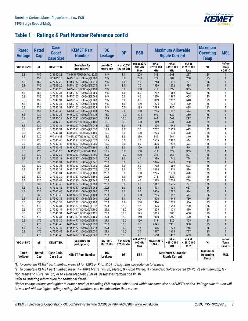
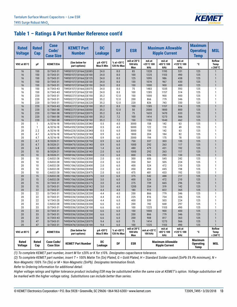
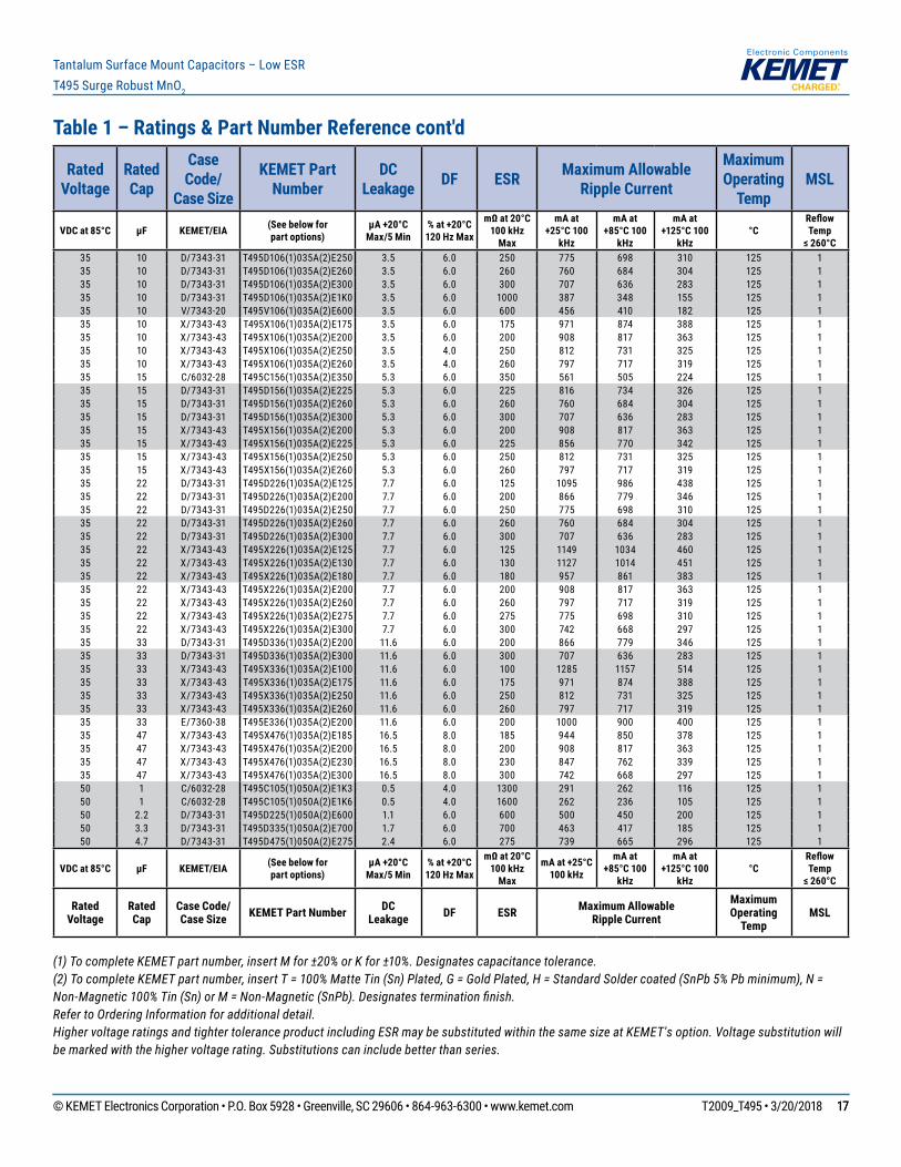
Table 1 – Ratings & Part Number Reference cont'd
(1) To complete KEMET part number, insert M for ±20% or K for ±10%. Designates capacitance tolerance.(2) To complete KEMET part number, insert T = 100% Matte Tin (Sn) Plated, G = Gold Plated, H = Standard Solder coated (SnPb 5% Pb minimum), N = Non-Magnetic 100% Tin (Sn) or M = Non-Magnetic (SnPb). Designates termination finish.Refer to Ordering Information for additional detail.Higher voltage ratings and tighter tolerance product including ESR may be substituted within the same size at KEMET's option. Voltage substitution will be marked with the higher voltage rating. Substitutions can include better than series.
Rated Voltage
Rated Cap
Case Code/
Case Size
KEMET Part Number
DC Leakage DF ESR Maximum Allowable
Ripple Current
Maximum Operating
TempMSL
VDC at 85°C µF KEMET/EIA (See below forpart options)
µA +20°CMax/5 Min
% at +20°C120 Hz Max
mΩ at 20°C100 kHz
Max
mA at +25°C 100
kHz
mA at +85°C 100
kHz
mA at +125°C 100
kHz °C
Reflow Temp
≤ 260°C6.3 6.8 A/3216-18 T495A685(1)006A(2)E4K5 0.5 6.0 4500 129 116 52 125 16.3 6.8 C/6032-28 T495C685(1)006A(2)E480 0.5 6.0 480 479 431 192 125 16.3 10 A/3216-18 T495A106(1)006A(2)E800 0.6 6.0 800 306 275 122 125 16.3 10 A/3216-18 T495A106(1)006A(2)E1K0 0.6 6.0 1000 274 247 110 125 16.3 10 A/3216-18 T495A106(1)006A(2)E1K5 0.6 6.0 1500 224 202 90 125 16.3 10 A/3216-18 T495A106(1)006A(2)E2K0 0.6 6.0 2000 194 175 78 125 16.3 10 B/3528-21 T495B106(1)006A(2)E1K0 0.6 6.0 1000 292 263 117 125 16.3 10 T/3528-12 T495T106(1)006A(2)E1K2 0.6 6.0 1200 242 218 97 125 16.3 15 A/3216-18 T495A156(1)006A(2)E2K0 0.9 6.0 2000 194 175 78 125 16.3 15 T/3528-12 T495T156(1)006A(2)E1K0 0.9 6.0 1000 265 239 106 125 16.3 22 A/3216-18 T495A226(1)006A(2)E500 1.4 6.0 500 387 348 155 125 16.3 22 A/3216-18 T495A226(1)006A(2)E900 1.4 8.0 900 289 260 116 125 16.3 22 A/3216-18 T495A226(1)006A(2)E1K5 1.4 8.0 1500 224 202 90 125 16.3 22 B/3528-21 T495B226(1)006A(2)E500 1.4 6.0 500 412 371 165 125 16.3 22 C/6032-28 T495C226(1)006A(2)E380 1.4 6.0 380 538 484 215 125 16.3 33 A/3216-18 T495A336(1)006A(2)E600 2.1 12.0 600 354 319 142 125 16.3 33 B/3528-21 T495B336(1)006A(2)E600 2.1 6.0 600 376 338 150 125 16.3 33 T/3528-12 T495T336(1)006A(2)E800 2.1 6.0 800 296 266 118 125 16.3 33 C/6032-28 T495C336(1)006A(2)E350 2.1 6.0 350 561 505 224 125 16.3 47 B/3528-21 T495B476(1)006A(2)E250 3.0 6.0 250 583 525 233 125 16.3 47 B/3528-21 T495B476(1)006A(2)E500 3.0 6.0 500 583 525 233 125 16.3 47 B/3528-21 T495B476(1)006A(2)E450 3.0 6.0 450 435 392 174 125 16.3 47 B/3528-21 T495B476(1)006A(2)E400 3.0 6.0 400 461 415 184 125 16.3 47 C/6032-28 T495C476(1)006A(2)E250 3.0 6.0 250 663 597 265 125 16.3 47 C/6032-28 T495C476(1)006A(2)E300 3.0 6.0 300 606 545 242 125 16.3 47 C/6032-28 T495C476(1)006A(2)E330 3.0 6.0 330 577 519 231 125 16.3 47 V/7343-20 T495V476(1)006A(2)E150 3.0 6.0 150 913 822 365 125 16.3 68 B/3528-21 T495B686(1)006A(2)E500 4.3 8.0 500 412 371 165 125 16.3 68 C/6032-28 T495C686(1)006A(2)E400 4.3 6.0 400 524 472 210 125 16.3 68 U/6032-15 T495U686(1)006A(2)E400 4.3 6.0 400 474 427 190 125 16.3 68 D/7343-31 T495D686(1)006A(2)E175 4.3 4.0 175 926 833 370 125 16.3 68 D/7343-31 T495D686(1)006A(2)E180 4.3 4.0 180 913 822 365 125 16.3 100 B/3528-21 T495B107(1)006A(2)E400 6.3 15.0 400 461 415 184 125 16.3 100 B/3528-21 T495B107(M)006A(2)E700 6.3 15.0 700 348 313 139 125 16.3 100 M/3528-15 T495M107(1)006A(2)E500 6.3 20.0 500 490 441 196 125 16.3 100 M/3528-15 T495M107(1)006A(2)E1K0 6.3 20.0 1000 346 311 138 125 16.3 100 C/6032-28 T495C107(1)006A(2)E075 6.3 8.0 75 1211 1090 484 125 16.3 100 C/6032-28 T495C107(1)006A(2)E150 6.3 8.0 150 856 770 342 125 16.3 100 D/7343-31 T495D107(1)006A(2)E050 6.3 6.0 50 1732 1559 693 125 16.3 100 D/7343-31 T495D107(1)006A(2)E130 6.3 6.0 130 1074 967 430 125 16.3 100 D/7343-31 T495D107(1)006A(2)E150 6.3 8.0 150 1000 900 400 125 16.3 100 D/7343-31 T495D107(1)006A(2)E800 6.3 6.0 800 433 390 173 125 16.3 100 V/7343-20 T495V107(1)006A(2)E090 6.3 8.0 90 1179 1061 472 125 16.3 100 V/7343-20 T495V107(1)006A(2)E150 6.3 8.0 150 913 822 365 125 16.3 150 C/6032-28 T495C157(1)006A(2)E050 9.5 8.0 50 1483 1335 593 125 1
VDC at 85°C µF KEMET/EIA (See below forpart options)
µA +20°CMax/5 Min
% at +20°C120 Hz Max
mΩ at 20°C100 kHz
Max
mA at +25°C 100 kHz
mA at +85°C 100
kHz
mA at +125°C 100
kHz °C
Reflow Temp
≤ 260°C
Rated Voltage
Rated Cap
Case Code/ Case Size KEMET Part Number DC
Leakage DF ESR Maximum Allowable Ripple Current
Maximum Operating
TempMSL
© KEMET Electronics Corporation • P.O. Box 5928 • Greenville, SC 29606 • 864-963-6300 • www.kemet.com T2009_T495 • 3/20/2018 77
Tantalum Surface Mount Capacitors – Low ESRT495 Surge Robust MnO2
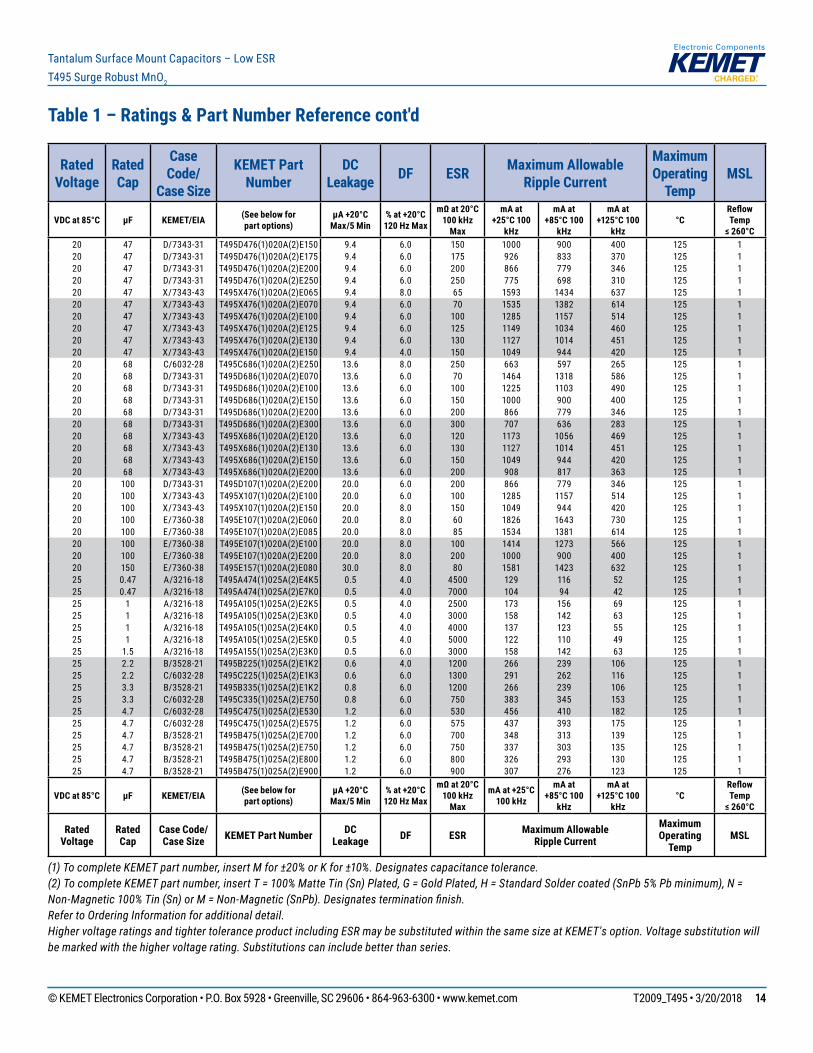
Table 1 – Ratings & Part Number Reference cont'd
(1) To complete KEMET part number, insert M for ±20% or K for ±10%. Designates capacitance tolerance.(2) To complete KEMET part number, insert T = 100% Matte Tin (Sn) Plated, G = Gold Plated, H = Standard Solder coated (SnPb 5% Pb minimum), N = Non-Magnetic 100% Tin (Sn) or M = Non-Magnetic (SnPb). Designates termination finish.Refer to Ordering Information for additional detail.Higher voltage ratings and tighter tolerance product including ESR may be substituted within the same size at KEMET's option. Voltage substitution will be marked with the higher voltage rating. Substitutions can include better than series.
Rated Voltage
Rated Cap
Case Code/
Case Size
KEMET Part Number
DC Leakage DF ESR Maximum Allowable
Ripple Current
Maximum Operating
TempMSL
VDC at 85°C µF KEMET/EIA (See below forpart options)
µA +20°CMax/5 Min
% at +20°C120 Hz Max
mΩ at 20°C100 kHz
Max
mA at +25°C 100
kHz
mA at +85°C 100
kHz
mA at +125°C 100
kHz °C
Reflow Temp
≤ 260°C6.3 150 C/6032-28 T495C157(M)006A(2)E200 9.5 8.0 200 742 668 297 125 16.3 150 U/6032-15 T495U157(1)006A(2)E200 9.5 8.0 200 671 604 268 125 16.3 150 V/7343-20 T495V157(1)006A(2)E040 9.5 8.0 40 1768 1591 707 125 16.3 150 V/7343-20 T495V157(1)006A(2)E070 9.5 8.0 70 1336 1202 534 125 16.3 150 V/7343-20 T495V157(1)006A(2)E150 9.5 8.0 150 913 822 365 125 16.3 150 D/7343-31 T495D157(1)006A(2)E050 9.5 6.0 50 1732 1559 693 125 16.3 150 D/7343-31 T495D157(1)006A(2)E065 9.5 6.0 65 1519 1367 608 125 16.3 150 D/7343-31 T495D157(1)006A(2)E080 9.5 6.0 80 1369 1232 548 125 16.3 150 D/7343-31 T495D157(1)006A(2)E100 9.5 6.0 100 1225 1103 490 125 16.3 150 D/7343-31 T495D157(1)006A(2)E125 9.5 6.0 125 1095 986 438 125 16.3 150 X/7343-43 T495X157(1)006A(2)E100 9.5 6.0 100 1285 1157 514 125 16.3 220 C/6032-28 T495C227(1)006A(2)E225 13.9 10.0 225 699 629 280 125 16.3 220 C/6032-28 T495C227(1)006A(2)E200 13.9 10.0 200 742 668 297 125 16.3 220 C/6032-28 T495C227(1)006A(2)E100 13.9 10.0 100 1049 944 420 125 16.3 220 D/7343-31 T495D227(1)006A(2)E045 13.9 8.0 45 1826 1643 730 125 16.3 220 D/7343-31 T495D227(1)006A(2)E050 13.9 8.0 50 1732 1559 693 125 16.3 220 D/7343-31 T495D227(1)006A(2)E100 13.9 8.0 100 1225 1103 490 125 16.3 220 W/7343-15 T495W227(1)006A(2)E250 13.9 8.0 250 849 764 340 125 16.3 220 X/7343-43 T495X227(1)006A(2)E070 13.9 8.0 70 1535 1382 614 125 16.3 220 X/7343-43 T495X227(1)006A(2)E080 13.9 8.0 80 1436 1292 574 125 16.3 220 X/7343-43 T495X227(1)006A(2)E100 13.9 8.0 100 1285 1157 514 125 16.3 220 V/7343-20 T495V227(1)006ATE150 13.9 8.0 150 913 822 365 125 16.3 330 C/6032-28 T495C337(1)006A(2)E200 20.8 18.0 200 742 668 297 125 16.3 330 D/7343-31 T495D337(1)006A(2)E040 20.8 8.0 40 1936 1742 774 125 16.3 330 D/7343-31 T495D337(1)006A(2)E045 20.8 8.0 45 1826 1643 730 125 16.3 330 D/7343-31 T495D337(1)006A(2)E050 20.8 8.0 50 1732 1559 693 125 16.3 330 D/7343-31 T495D337(1)006A(2)E070 20.8 8.0 70 1464 1318 586 125 16.3 330 D/7343-31 T495D337(1)006A(2)E100 20.8 8.0 100 1225 1103 490 125 16.3 330 V/7343-20 T495V337(1)006A(2)E150 20.8 8.0 150 913 822 365 125 16.3 330 X/7343-43 T495X337(1)006A(2)E045 20.8 8.0 45 1915 1724 766 125 16.3 330 X/7343-43 T495X337(1)006A(2)E050 20.8 8.0 50 1817 1635 727 125 16.3 330 X/7343-43 T495X337(1)006A(2)E065 20.8 8.0 65 1593 1434 637 125 16.3 330 X/7343-43 T495X337(1)006A(2)E080 20.8 8.0 80 1436 1292 574 125 16.3 330 X/7343-43 T495X337(1)006A(2)E100 20.8 8.0 100 1285 1157 514 125 16.3 330 E/7360-38 T495E337(1)006A(2)E060 20.8 8.0 60 1826 1643 730 125 16.3 330 E/7360-38 T495E337(1)006A(2)E100 20.8 8.0 100 1414 1273 566 125 16.3 470 D/7343-31 T495D477(1)006A(2)E045 29.6 12.0 45 1826 1643 730 125 16.3 470 D/7343-31 T495D477(1)006A(2)E100 29.6 12.0 100 1225 1103 490 125 16.3 470 D/7343-31 T495D477(1)006A(2)E125 29.6 12.0 125 1095 986 438 125 16.3 470 D/7343-31 T495D477(1)006A(2)E150 29.6 12.0 150 1000 900 400 125 16.3 470 V/7343-20 T495V477(1)006A(2)E150 29.6 15.0 150 913 822 365 125 16.3 470 X/7343-43 T495X477(1)006A(2)E030 29.6 10.0 30 2345 2111 938 125 16.3 470 X/7343-43 T495X477(1)006A(2)E045 29.6 10.0 45 1915 1724 766 125 16.3 470 X/7343-43 T495X477(1)006A(2)E050 29.6 10.0 50 1817 1635 727 125 16.3 470 X/7343-43 T495X477(1)006A(2)E060 29.6 10.0 60 1658 1492 663 125 1
VDC at 85°C µF KEMET/EIA (See below forpart options)
µA +20°CMax/5 Min
% at +20°C120 Hz Max
mΩ at 20°C100 kHz
Max
mA at +25°C 100 kHz
mA at +85°C 100
kHz
mA at +125°C 100
kHz °C
Reflow Temp
≤ 260°C
Rated Voltage
Rated Cap
Case Code/ Case Size KEMET Part Number DC
Leakage DF ESR Maximum Allowable Ripple Current
Maximum Operating
TempMSL
© KEMET Electronics Corporation • P.O. Box 5928 • Greenville, SC 29606 • 864-963-6300 • www.kemet.com T2009_T495 • 3/20/2018 88
Tantalum Surface Mount Capacitors – Low ESRT495 Surge Robust MnO2
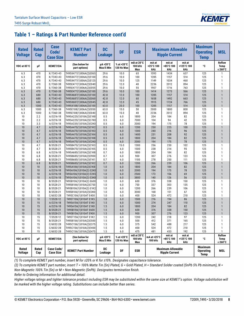
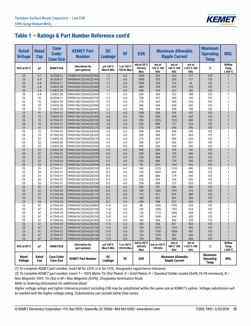
Table 1 – Ratings & Part Number Reference cont'd
(1) To complete KEMET part number, insert M for ±20% or K for ±10%. Designates capacitance tolerance.(2) To complete KEMET part number, insert T = 100% Matte Tin (Sn) Plated, G = Gold Plated, H = Standard Solder coated (SnPb 5% Pb minimum), N = Non-Magnetic 100% Tin (Sn) or M = Non-Magnetic (SnPb). Designates termination finish.Refer to Ordering Information for additional detail.Higher voltage ratings and tighter tolerance product including ESR may be substituted within the same size at KEMET's option. Voltage substitution will be marked with the higher voltage rating. Substitutions can include better than series.
Rated Voltage
Rated Cap
Case Code/
Case Size
KEMET Part Number
DC Leakage DF ESR Maximum Allowable
Ripple Current
Maximum Operating
TempMSL
VDC at 85°C µF KEMET/EIA (See below forpart options)
µA +20°CMax/5 Min
% at +20°C120 Hz Max
mΩ at 20°C100 kHz
Max
mA at +25°C 100
kHz
mA at +85°C 100
kHz
mA at +125°C 100
kHz °C
Reflow Temp
≤ 260°C6.3 470 X/7343-43 T495X477(1)006A(2)E065 29.6 10.0 65 1593 1434 637 125 16.3 470 X/7343-43 T495X477(1)006A(2)E100 29.6 10.0 100 1285 1157 514 125 16.3 470 X/7343-43 T495X477(1)006A(2)E125 29.6 10.0 125 1149 1034 460 125 16.3 470 E/7360-38 T495E477(1)006A(2)E040 29.6 12.0 40 2236 2012 894 125 16.3 470 E/7360-38 T495E477(1)006A(2)E055 29.6 10.0 55 1907 1716 763 125 16.3 470 E/7360-38 T495E477(1)006A(2)E100 29.6 10.0 100 1414 1273 566 125 16.3 680 X/7343-43 T495X687(1)006A(2)E100 42.8 12.0 100 1285 1157 514 125 16.3 680 X/7343-43 T495X687(1)006A(2)E060 42.8 12.0 60 1658 1492 663 125 16.3 680 X/7343-43 T495X687(1)006A(2)E045 42.8 12.0 45 1915 1724 766 125 16.3 1000 X/7343-43 T495X108(1)006A(2)E100 63.0 20.0 100 1285 1157 514 125 16.3 1000 E/7360-38 T495E108(1)006A(2)E050 63.0 15.0 50 2000 1800 800 125 16.3 1000 E/7360-38 T495E108(1)006A(2)E040 63.0 15.0 40 2236 2012 894 125 110 2.2 A/3216-18 T495A225(1)010A(2)E1K8 0.5 6.0 1800 204 184 82 125 110 2.2 A/3216-18 T495A225(1)010A(2)E7K0 0.5 6.0 7000 104 94 42 125 110 3.3 A/3216-18 T495A335(1)010A(2)E2K0 0.5 6.0 2000 194 175 78 125 110 4.7 A/3216-18 T495A475(1)010A(2)E1K2 0.5 6.0 1200 250 225 100 125 110 4.7 A/3216-18 T495A475(1)010A(2)E1K3 0.5 6.0 1300 240 216 96 125 110 4.7 A/3216-18 T495A475(1)010A(2)E1K4 0.5 6.0 1400 231 208 92 125 110 4.7 A/3216-18 T495A475(1)010A(2)E1K8 0.5 6.0 1800 204 184 82 125 110 4.7 A/3216-18 T495A475(1)010A(2)E2K0 0.5 6.0 2000 194 175 78 125 110 4.7 B/3528-21 T495B475(1)010A(2)E1K3 0.5 15.0 1300 256 230 102 125 110 4.7 B/3528-21 T495B475(1)010A(2)E1K5 0.5 6.0 1500 238 214 95 125 110 6.8 A/3216-18 T495A685(1)010A(2)E1K8 0.7 6.0 1800 204 184 82 125 110 6.8 B/3528-21 T495B685(1)010A(2)E900 0.7 6.0 900 307 276 123 125 110 6.8 B/3528-21 T495B685(1)010A(2)E1K1 0.7 6.0 1100 278 250 111 125 110 6.8 B/3528-21 T495B685(1)010A(2)E1K2 0.7 6.0 1200 266 239 106 125 110 10 A/3216-18 T495A106(1)010A(2)E1K8 1.0 6.0 1800 204 184 82 125 110 10 A/3216-18 T495A106(1)010A(2) E2K0 1.0 6.0 2000 194 175 78 125 110 10 A/3216-18 T495A106(1)010A(2) E2K5 1.0 6.0 2500 173 156 69 125 110 10 A/3216-18 T495A106(1)010A(2) E3K8 1.0 6.0 3800 140 126 56 125 110 10 B/3528-21 T495B106(1)010A(2) E600 1.0 6.0 600 376 338 150 125 110 10 B/3528-21 T495B106(1)010A(2)E750 1.0 6.0 750 337 303 135 125 110 10 B/3528-21 T495B106(1)010A(2) E1K2 1.0 6.0 1200 266 239 106 125 110 10 B/3528-21 T495B106(1)010A(2)E3K0 1.0 6.0 3000 168 151 67 125 110 10 C/6032-28 T495C106(1)010AT E400 1.0 6.0 400 524 472 210 125 110 10 T/3528-12 T495T106(1)010AT E1K5 1.0 6.0 1500 216 194 86 125 110 15 A/3216-18 T495A156(1)010AT E1K0 1.5 6.0 1000 274 247 110 125 110 15 A/3216-18 T495A156(1)010AT E1K8 1.5 6.0 1800 204 184 82 125 110 15 B/3528-21 T495B156(1)010AT E600 1.5 6.0 600 376 338 150 125 110 15 B/3528-21 T495B156(1)010AT E900 1.5 6.0 900 307 276 123 125 110 15 T/3528-12 T495T156(1)010AT E1K2 1.5 6.0 1200 242 218 97 125 110 15 B/3528-21 T495B156(1)010A(2)E500 1.5 6.0 500 412 371 165 125 110 15 C/6032-28 T495C156(1)010A(2)E375 1.5 6.0 375 542 488 217 125 110 15 C/6032-28 T495C156(1)010A(2)E400 1.5 6.0 400 524 472 210 125 110 15 C/6032-28 T495C156(1)010A(2)E475 1.5 6.0 475 481 433 192 125 1
VDC at 85°C µF KEMET/EIA (See below forpart options)
µA +20°CMax/5 Min
% at +20°C120 Hz Max
mΩ at 20°C100 kHz
Max
mA at +25°C 100 kHz
mA at +85°C 100
kHz
mA at +125°C 100
kHz °C
Reflow Temp
≤ 260°C
Rated Voltage
Rated Cap
Case Code/ Case Size KEMET Part Number DC
Leakage DF ESR Maximum Allowable Ripple Current
Maximum Operating
TempMSL
© KEMET Electronics Corporation • P.O. Box 5928 • Greenville, SC 29606 • 864-963-6300 • www.kemet.com T2009_T495 • 3/20/2018 99
Tantalum Surface Mount Capacitors – Low ESRT495 Surge Robust MnO2
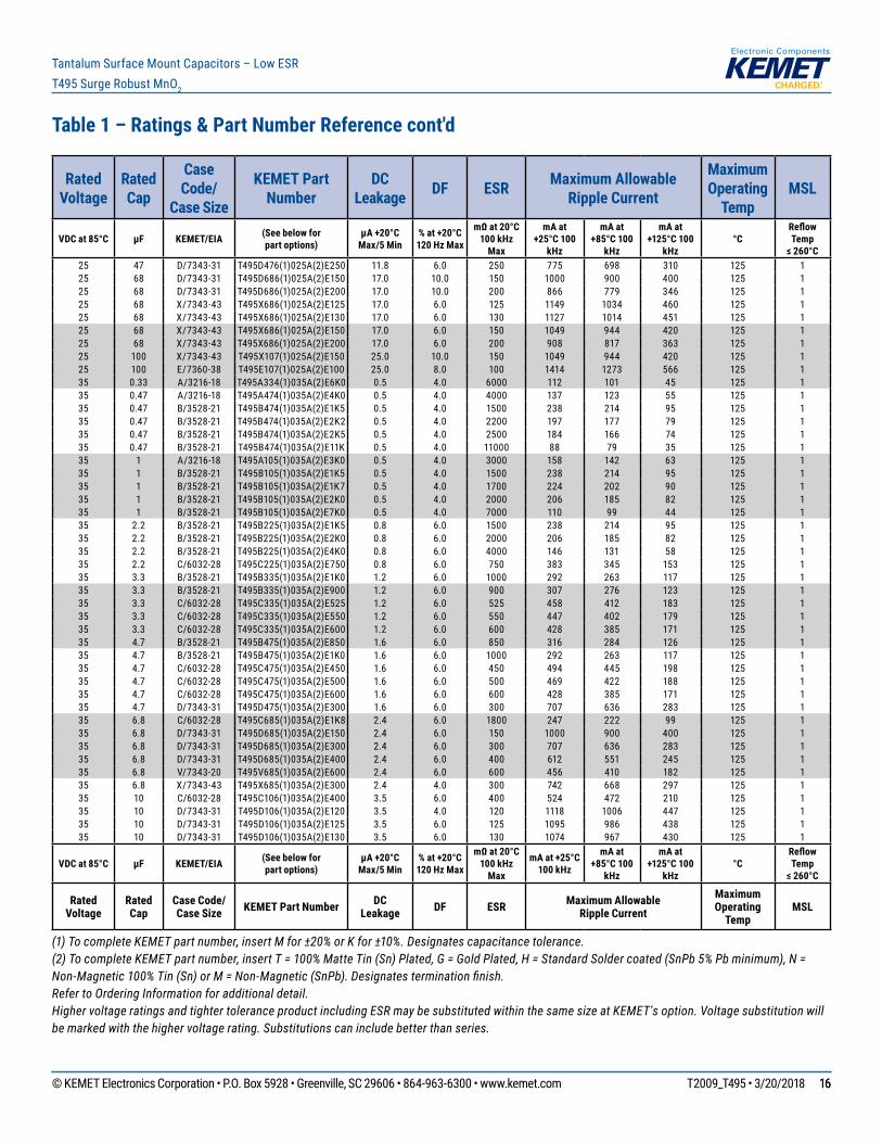
Table 1 – Ratings & Part Number Reference cont'd
(1) To complete KEMET part number, insert M for ±20% or K for ±10%. Designates capacitance tolerance.(2) To complete KEMET part number, insert T = 100% Matte Tin (Sn) Plated, G = Gold Plated, H = Standard Solder coated (SnPb 5% Pb minimum), N = Non-Magnetic 100% Tin (Sn) or M = Non-Magnetic (SnPb). Designates termination finish.Refer to Ordering Information for additional detail.Higher voltage ratings and tighter tolerance product including ESR may be substituted within the same size at KEMET's option. Voltage substitution will be marked with the higher voltage rating. Substitutions can include better than series.
Rated Voltage
Rated Cap
Case Code/
Case Size
KEMET Part Number
DC Leakage DF ESR Maximum Allowable
Ripple Current
Maximum Operating
TempMSL
VDC at 85°C µF KEMET/EIA (See below forpart options)
µA +20°CMax/5 Min
% at +20°C120 Hz Max
mΩ at 20°C100 kHz
Max
mA at +25°C 100
kHz
mA at +85°C 100
kHz
mA at +125°C 100
kHz °C
Reflow Temp
≤ 260°C10 22 A/3216-18 T495A226(1)010AT E1K2 2.2 8.0 1200 250 225 100 125 110 22 A/3216-18 T495A226(1)010AT E1K5 2.2 8.0 1500 224 202 90 125 110 22 B/3528-21 T495B226(1)010AT E400 2.2 6.0 400 461 415 184 125 110 22 B/3528-21 T495B226(1)010AT E500 2.2 6.0 500 412 371 165 125 110 22 B/3528-21 T495B226(1)010AT E700 2.2 6.0 700 348 313 139 125 110 22 B/3528-21 T495B226(1)010AT E800 2.2 6.0 800 326 293 130 125 110 22 B/3528-21 T495B226(1)010A(2)E2K3 2.2 6.0 2300 192 173 77 125 110 22 C/6032-28 T495C226(1)010A(2)E200 2.2 6.0 200 742 668 297 125 110 22 C/6032-28 T495C226(1)010A(2)E245 2.2 6.0 245 670 603 268 125 110 22 C/6032-28 T495C226(1)010A(2)E290 2.2 6.0 290 616 554 246 125 110 22 C/6032-28 T495C226(1)010A(2)E300 2.2 6.0 300 606 545 242 125 110 22 C/6032-28 T495C226(1)010A(2)E345 2.2 6.0 345 565 509 226 125 110 22 C/6032-28 T495C226(1)010A(2)E350 2.2 6.0 350 561 505 224 125 110 22 C/6032-28 T495C226(1)010A(2)E380 2.2 6.0 380 538 484 215 125 110 33 B/3528-21 T495B336(1)010A(2)E450 3.3 6.0 450 435 392 174 125 110 33 B/3528-21 T495B336(1)010A(2)E550 3.3 6.0 550 393 354 157 125 110 33 B/3528-21 T495B336(1)010A(2)E650 3.3 6.0 650 362 326 145 125 110 33 V/7343-20 T495V336(1)010A(2)E100 3.3 6.0 100 1118 1006 447 125 110 33 V/7343-20 T495V336(1)010A(2)E150 3.3 6.0 150 913 822 365 125 110 47 B/3528-21 T495B476(1)010A(2)E500 4.7 6.0 500 412 371 165 125 110 47 B/3528-21 T495B476(1)010A(2)E650 4.7 6.0 650 362 326 145 125 110 47 C/6032-28 T495C476(1)010A(2)E300 4.7 6.0 300 606 545 242 125 110 47 U/6032-15 T495U476(1)010A(2)E400 4.7 6.0 400 474 427 190 125 110 47 D/7343-31 T495D476(1)010A(2)E080 4.7 4.0 80 1369 1232 548 125 110 47 D/7343-31 T495D476(1)010A(2)E090 4.7 6.0 90 1291 1162 516 125 110 47 D/7343-31 T495D476(1)010A(2)E100 4.7 6.0 100 1225 1103 490 125 110 47 D/7343-31 T495D476(1)010A(2)E200 4.7 4.0 200 866 779 346 125 110 47 V/7343-20 T495V476(1)010A(2)E200 4.7 6.0 200 791 712 316 125 110 68 B/3528-21 T495B686(1)010A(2)E600 6.8 8.0 600 376 338 150 125 110 68 B/3528-21 T495B686(1)010A(2)E750 6.8 8.0 750 337 303 135 125 110 68 B/3528-21 T495B686(M)010A(2)E900 6.8 8.0 900 307 276 123 125 110 68 C/6032-28 T495C686(1)010A(2)E080 6.8 6.0 80 1173 1056 469 125 110 68 C/6032-28 T495C686(1)010A(2)E200 6.8 6.0 200 742 668 297 125 110 68 C/6032-28 T495C686(1)010A(2)E225 6.8 6.0 225 699 629 280 125 110 68 C/6032-28 T495C686(1)010A(2)E250 6.8 6.0 250 663 597 265 125 110 68 V/7343-20 T495V686(1)010A(2)E070 6.8 6.0 70 1336 1202 534 125 110 68 V/7343-20 T495V686(1)010A(2)E100 6.8 6.0 100 1118 1006 447 125 110 68 V/7343-20 T495V686(1)010A(2)E140 6.8 6.0 140 945 851 378 125 110 68 V/7343-20 T495V686(1)010A(2)E200 6.8 6.0 200 791 712 316 125 110 68 D/7343-31 T495D686(1)010A(2)E070 6.8 6.0 70 1464 1318 586 125 110 68 D/7343-31 T495D686(1)010A(2)E090 6.8 6.0 90 1291 1162 516 125 110 68 D/7343-31 T495D686(1)010A(2)E100 6.8 6.0 100 1225 1103 490 125 110 68 D/7343-31 T495D686(1)010A(2)E150 6.8 6.0 150 1000 900 400 125 110 68 X/7343-43 T495X686(1)010A(2)E150 6.8 4.0 150 1049 944 420 125 110 100 B/3528-21 T495B107(M)010A(2)E350 10.0 12.0 350 493 444 197 125 1
VDC at 85°C µF KEMET/EIA (See below forpart options)
µA +20°CMax/5 Min
% at +20°C120 Hz Max
mΩ at 20°C100 kHz
Max
mA at +25°C 100 kHz
mA at +85°C 100
kHz
mA at +125°C 100
kHz °C
Reflow Temp
≤ 260°C
Rated Voltage
Rated Cap
Case Code/ Case Size KEMET Part Number DC
Leakage DF ESR Maximum Allowable Ripple Current
Maximum Operating
TempMSL
© KEMET Electronics Corporation • P.O. Box 5928 • Greenville, SC 29606 • 864-963-6300 • www.kemet.com T2009_T495 • 3/20/2018 1010
Tantalum Surface Mount Capacitors – Low ESRT495 Surge Robust MnO2
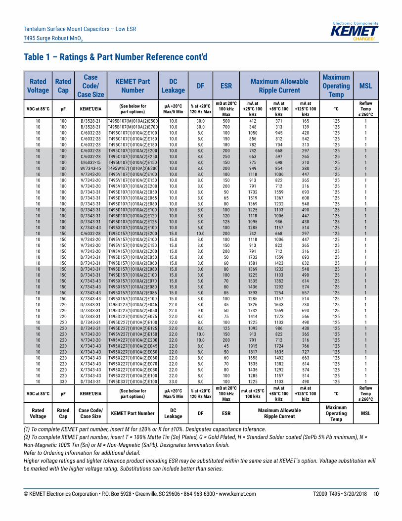
Table 1 – Ratings & Part Number Reference cont'd
(1) To complete KEMET part number, insert M for ±20% or K for ±10%. Designates capacitance tolerance.(2) To complete KEMET part number, insert T = 100% Matte Tin (Sn) Plated, G = Gold Plated, H = Standard Solder coated (SnPb 5% Pb minimum), N = Non-Magnetic 100% Tin (Sn) or M = Non-Magnetic (SnPb). Designates termination finish.Refer to Ordering Information for additional detail.Higher voltage ratings and tighter tolerance product including ESR may be substituted within the same size at KEMET's option. Voltage substitution will be marked with the higher voltage rating. Substitutions can include better than series.
Rated Voltage
Rated Cap
Case Code/
Case Size
KEMET Part Number
DC Leakage DF ESR Maximum Allowable
Ripple Current
Maximum Operating
TempMSL
VDC at 85°C µF KEMET/EIA (See below forpart options)
µA +20°CMax/5 Min
% at +20°C120 Hz Max
mΩ at 20°C100 kHz
Max
mA at +25°C 100
kHz
mA at +85°C 100
kHz
mA at +125°C 100
kHz °C
Reflow Temp
≤ 260°C10 100 B/3528-21 T495B107(M)010A(2)E500 10.0 30.0 500 412 371 165 125 110 100 B/3528-21 T495B107(M)010A(2)E700 10.0 30.0 700 348 313 139 125 110 100 C/6032-28 T495C107(1)010A(2)E100 10.0 8.0 100 1050 945 420 125 110 100 C/6032-28 T495C107(1)010A(2)E150 10.0 8.0 150 856 812 542 125 110 100 C/6032-28 T495C107(1)010A(2)E180 10.0 8.0 180 782 704 313 125 110 100 C/6032-28 T495C107(1)010A(2)E200 10.0 8.0 200 742 668 297 125 110 100 C/6032-28 T495C107(1)010A(2)E250 10.0 8.0 250 663 597 265 125 110 100 U/6032-15 T495U107(1)010A(2)E150 10.0 8.0 150 775 698 310 125 110 100 W/7343-15 T495W107(1)010A(2)E200 10.0 8.0 200 949 854 380 125 110 100 V/7343-20 T495V107(1)010A(2)E100 10.0 8.0 100 1118 1006 447 125 110 100 V/7343-20 T495V107(1)010A(2)E150 10.0 8.0 150 913 822 365 125 110 100 V/7343-20 T495V107(1)010A(2)E200 10.0 8.0 200 791 712 316 125 110 100 D/7343-31 T495D107(1)010A(2)E050 10.0 8.0 50 1732 1559 693 125 110 100 D/7343-31 T495D107(1)010A(2)E065 10.0 8.0 65 1519 1367 608 125 110 100 D/7343-31 T495D107(1)010A(2)E080 10.0 8.0 80 1369 1232 548 125 110 100 D/7343-31 T495D107(1)010A(2)E100 10.0 8.0 100 1225 1103 490 125 110 100 D/7343-31 T495D107(1)010A(2)E120 10.0 8.0 120 1118 1006 447 125 110 100 D/7343-31 T495D107(1)010A(2)E125 10.0 8.0 125 1095 986 438 125 110 100 X/7343-43 T495X107(1)010A(2)E100 10.0 6.0 100 1285 1157 514 125 110 150 C/6032-28 T495C157(1)010A(2)E200 15.0 10.0 200 742 668 297 125 110 150 V/7343-20 T495V157(1)010A(2)E100 15.0 8.0 100 1118 1006 447 125 110 150 V/7343-20 T495V157(1)010A(2)E150 15.0 8.0 150 913 822 365 125 110 150 V/7343-20 T495V157(1)010A(2)E200 15.0 8.0 200 791 712 316 125 110 150 D/7343-31 T495D157(1)010A(2)E050 15.0 8.0 50 1732 1559 693 125 110 150 D/7343-31 T495D157(1)010A(2)E060 15.0 8.0 60 1581 1423 632 125 110 150 D/7343-31 T495D157(1)010A(2)E080 15.0 8.0 80 1369 1232 548 125 110 150 D/7343-31 T495D157(1)010A(2)E100 15.0 8.0 100 1225 1103 490 125 110 150 X/7343-43 T495X157(1)010A(2)E070 15.0 8.0 70 1535 1382 614 125 110 150 X/7343-43 T495X157(1)010A(2)E080 15.0 8.0 80 1436 1292 574 125 110 150 X/7343-43 T495X157(1)010A(2)E085 15.0 8.0 85 1393 1254 557 125 110 150 X/7343-43 T495X157(1)010A(2)E100 15.0 8.0 100 1285 1157 514 125 110 220 D/7343-31 T495D227(1)010A(2)E045 22.0 8.0 45 1826 1643 730 125 110 220 D/7343-31 T495D227(1)010A(2)E050 22.0 9.0 50 1732 1559 693 125 110 220 D/7343-31 T495D227(1)010A(2)E075 22.0 8.0 75 1414 1273 566 125 110 220 D/7343-31 T495D227(1)010A(2)E100 22.0 8.0 100 1225 1103 490 125 110 220 D/7343-31 T495D227(1)010A(2)E125 22.0 8.0 125 1095 986 438 125 110 220 V/7343-20 T495V227(1)010A(2)E150 22.0 10.0 150 913 822 365 125 110 220 V/7343-20 T495V227(1)010A(2)E200 22.0 10.0 200 791 712 316 125 110 220 X/7343-43 T495X227(1)010A(2)E045 22.0 8.0 45 1915 1724 766 125 110 220 X/7343-43 T495X227(1)010A(2)E050 22.0 8.0 50 1817 1635 727 125 110 220 X/7343-43 T495X227(1)010A(2)E060 22.0 8.0 60 1658 1492 663 125 110 220 X/7343-43 T495X227(1)010A(2)E070 22.0 8.0 70 1535 1382 614 125 110 220 X/7343-43 T495X227(1)010A(2)E080 22.0 8.0 80 1436 1292 574 125 110 220 X/7343-43 T495X227(1)010A(2)E100 22.0 8.0 100 1285 1157 514 125 110 330 D/7343-31 T495D337(1)010A(2)E100 33.0 8.0 100 1225 1103 490 125 1
VDC at 85°C µF KEMET/EIA (See below forpart options)
µA +20°CMax/5 Min
% at +20°C120 Hz Max
mΩ at 20°C100 kHz
Max
mA at +25°C 100 kHz
mA at +85°C 100
kHz
mA at +125°C 100
kHz °C
Reflow Temp
≤ 260°C
Rated Voltage
Rated Cap
Case Code/ Case Size KEMET Part Number DC
Leakage DF ESR Maximum Allowable Ripple Current
Maximum Operating
TempMSL
© KEMET Electronics Corporation • P.O. Box 5928 • Greenville, SC 29606 • 864-963-6300 • www.kemet.com T2009_T495 • 3/20/2018 1111
Tantalum Surface Mount Capacitors – Low ESRT495 Surge Robust MnO2
Table 1 – Ratings & Part Number Reference cont'd
(1) To complete KEMET part number, insert M for ±20% or K for ±10%. Designates capacitance tolerance.(2) To complete KEMET part number, insert T = 100% Matte Tin (Sn) Plated, G = Gold Plated, H = Standard Solder coated (SnPb 5% Pb minimum), N = Non-Magnetic 100% Tin (Sn) or M = Non-Magnetic (SnPb). Designates termination finish.Refer to Ordering Information for additional detail.Higher voltage ratings and tighter tolerance product including ESR may be substituted within the same size at KEMET's option. Voltage substitution will be marked with the higher voltage rating. Substitutions can include better than series.
Rated Voltage
Rated Cap
Case Code/
Case Size
KEMET Part Number
DC Leakage DF ESR Maximum Allowable
Ripple Current
Maximum Operating
TempMSL
VDC at 85°C µF KEMET/EIA (See below forpart options)
µA +20°CMax/5 Min
% at +20°C120 Hz Max
mΩ at 20°C100 kHz
Max
mA at +25°C 100
kHz
mA at +85°C 100
kHz
mA at +125°C 100
kHz °C
Reflow Temp
≤ 260°C10 330 D/7343-31 T495D337(1)010A(2)E125 33.0 10.0 125 1095 986 438 125 110 330 D/7343-31 T495D337(1)010A(2)E150 33.0 10.0 150 1000 900 400 125 110 330 X/7343-43 T495X337(1)010A(2)E035 33.0 10.0 35 2171 1954 868 125 110 330 X/7343-43 T495X337(1)010A(2)E040 33.0 10.0 40 2031 1828 812 125 110 330 X/7343-43 T495X337(1)010A(2)E050 33.0 10.0 50 1817 1635 727 125 110 330 X/7343-43 T495X337(1)010A(2)E060 33.0 10.0 60 1658 1492 663 125 110 330 X/7343-43 T495X337(1)010A(2)E080 33.0 10.0 80 1436 1292 574 125 110 330 X/7343-43 T495X337(1)010A(2)E100 33.0 10.0 100 1285 1157 514 125 110 330 E/7360-38 T495E337(1)010A(2)E040 33.0 8.0 40 2236 2012 894 125 110 330 E/7360-38 T495E337(1)010A(2)E060 33.0 10.0 60 1826 1643 730 125 110 330 E/7360-38 T495E337(1)010A(2)E100 33.0 10.0 100 1414 1273 566 125 110 470 X/7343-43 T495X477(1)010A(2)E045 47.0 10.0 45 1915 1724 766 125 110 470 X/7343-43 T495X477(1)010A(2)E050 47.0 10.0 50 1817 1635 727 125 110 470 X/7343-43 T495X477(1)010A(2)E060 47.0 10.0 60 1658 1492 663 125 110 470 X/7343-43 T495X477(1)010A(2)E080 47.0 10.0 80 1436 1292 574 125 110 470 X/7343-43 T495X477(1)010A(2)E100 47.0 10.0 100 1285 1157 514 125 110 470 X/7343-43 T495X477(1)010A(2)E200 47.0 10.0 200 908 817 363 125 110 470 E/7360-38 T495E477(1)010A(2)E040 47.0 10.0 40 2236 2012 894 125 110 470 E/7360-38 T495E477(1)010A(2)E060 47.0 10.0 60 1826 1643 730 125 110 470 E/7360-38 T495E477(1)010A(2)E100 47.0 10.0 100 1414 1273 566 125 116 1.0 A/3216-18 T495A105(1)016A(2)E5K0 0.5 6.0 5000 122 110 49 125 116 1.5 A/3216-18 T495A155(1)016A(2)E5K0 0.5 6.0 5000 122 110 49 125 116 2.2 A/3216-18 T495A225(1)016A(2)E2K5 0.5 6.0 2500 173 156 69 125 116 2.2 A/3216-18 T495A225(1)016A(2)E1K8 0.5 6.0 1800 204 184 82 125 116 3.3 A/3216-18 T495A335(1)016A(2)E3K0 0.5 6.0 3000 158 142 63 125 116 3.3 B/3528-21 T495B335(1)016A(2)E2K0 0.5 6.0 2000 206 185 82 125 116 4.7 A/3216-18 T495A475(1)016A(2)E2K0 0.8 6.0 2000 194 175 78 125 116 4.7 B/3528-21 T495B475(1)016A(2)E700 0.8 6.0 700 348 313 139 125 116 4.7 B/3528-21 T495B475(1)016A(2)E800 0.8 6.0 800 326 293 130 125 116 4.7 B/3528-21 T495B475(1)016A(2)E1K0 0.8 6.0 1000 292 263 117 125 116 4.7 B/3528-21 T495B475(1)016A(2)E1K5 0.8 6.0 1500 238 214 95 125 116 6.8 B/3528-21 T495B685(1)016A(2)E1K2 1.1 6.0 1200 266 239 106 125 116 6.8 C/6032-28 T495C685(1)016A(2)E750 1.1 6.0 750 383 345 153 125 116 10 A/3216-18 T495A106(1)016A(2)E1K7 1.6 6.0 1700 210 189 84 125 116 10 B/3528-21 T495B106(1)016A(2)E500 1.6 6.0 500 412 371 165 125 116 10 B/3528-21 T495B106(1)016A(2)E650 1.6 6.0 650 362 326 145 125 116 10 B/3528-21 T495B106(1)016A(2)E800 1.6 6.0 800 326 293 130 125 116 10 B/3528-21 T495B106(1)016A(2)E2K5 1.6 6.0 2500 184 166 74 125 116 10 T/3528-12 T495T106(M)016A(2)E4K0 1.6 8.0 4000 132 119 53 125 116 15 A/3216-18 T495A156(1)016A(2)E2K5 2.4 8.0 2500 173 156 69 125 116 15 B/3528-21 T495B156(1)016A(2)E500 2.4 6.0 500 412 371 165 125 116 15 B/3528-21 T495B156(1)016A(2)E650 2.4 6.0 650 362 326 145 125 116 15 B/3528-21 T495B156(1)016A(2)E800 2.4 6.0 800 326 293 130 125 116 15 C/6032-28 T495C156(1)016A(2)E400 2.4 6.0 400 524 472 210 125 116 22 B/3528-21 T495B226(1)016A(2)E600 3.5 6.0 600 376 338 150 125 1
VDC at 85°C µF KEMET/EIA (See below forpart options)
µA +20°CMax/5 Min
% at +20°C120 Hz Max
mΩ at 20°C100 kHz
Max
mA at +25°C 100 kHz
mA at +85°C 100
kHz
mA at +125°C 100
kHz °C
Reflow Temp
≤ 260°C
Rated Voltage
Rated Cap
Case Code/ Case Size KEMET Part Number DC
Leakage DF ESR Maximum Allowable Ripple Current
Maximum Operating
TempMSL
© KEMET Electronics Corporation • P.O. Box 5928 • Greenville, SC 29606 • 864-963-6300 • www.kemet.com T2009_T495 • 3/20/2018 1212
Tantalum Surface Mount Capacitors – Low ESRT495 Surge Robust MnO2
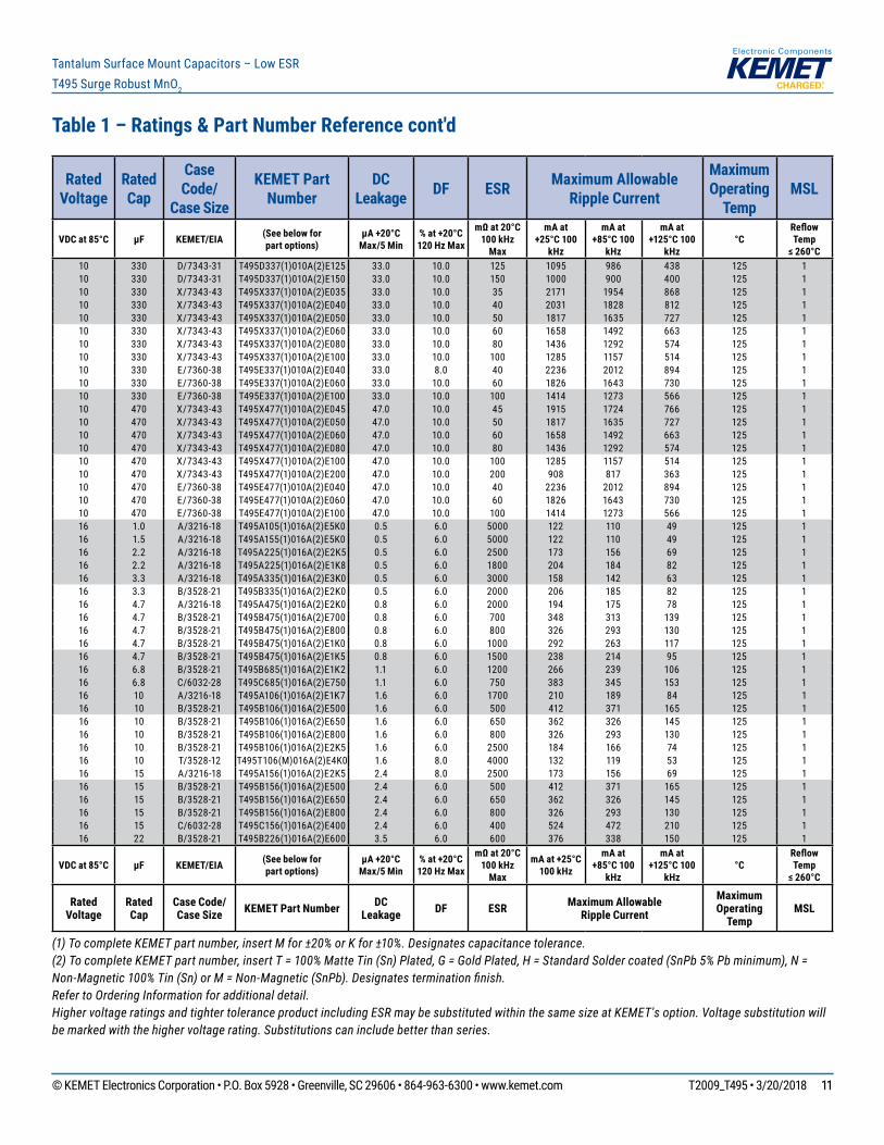
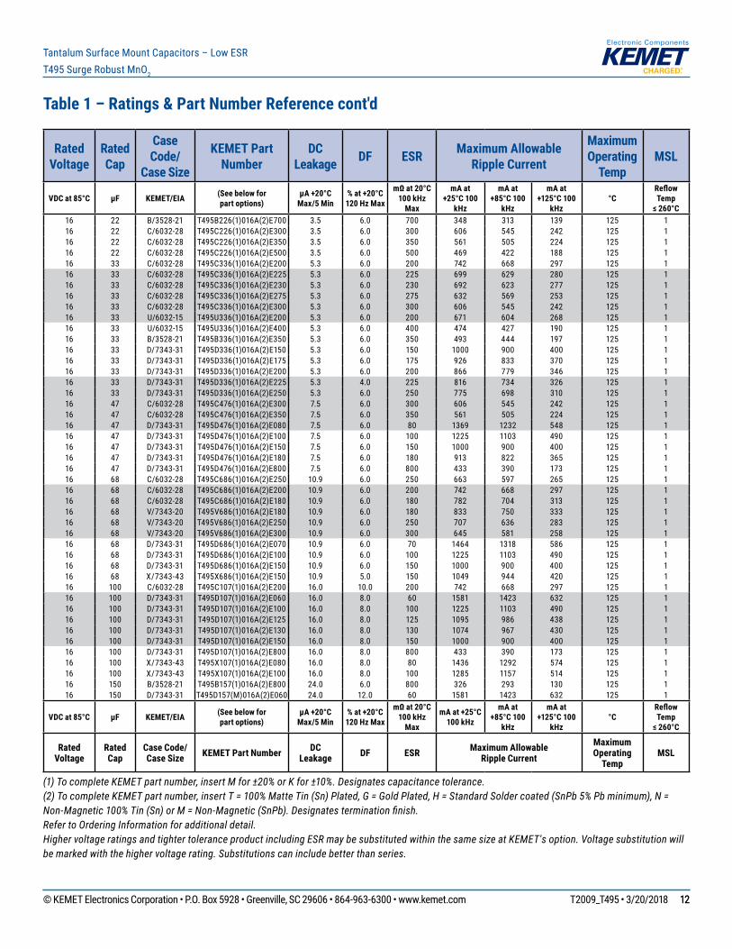
Table 1 – Ratings & Part Number Reference cont'd
(1) To complete KEMET part number, insert M for ±20% or K for ±10%. Designates capacitance tolerance.(2) To complete KEMET part number, insert T = 100% Matte Tin (Sn) Plated, G = Gold Plated, H = Standard Solder coated (SnPb 5% Pb minimum), N = Non-Magnetic 100% Tin (Sn) or M = Non-Magnetic (SnPb). Designates termination finish.Refer to Ordering Information for additional detail.Higher voltage ratings and tighter tolerance product including ESR may be substituted within the same size at KEMET's option. Voltage substitution will be marked with the higher voltage rating. Substitutions can include better than series.
Rated Voltage
Rated Cap
Case Code/
Case Size
KEMET Part Number
DC Leakage DF ESR Maximum Allowable
Ripple Current
Maximum Operating
TempMSL
VDC at 85°C µF KEMET/EIA (See below forpart options)
µA +20°CMax/5 Min
% at +20°C120 Hz Max
mΩ at 20°C100 kHz
Max
mA at +25°C 100
kHz
mA at +85°C 100
kHz
mA at +125°C 100
kHz °C
Reflow Temp
≤ 260°C16 22 B/3528-21 T495B226(1)016A(2)E700 3.5 6.0 700 348 313 139 125 116 22 C/6032-28 T495C226(1)016A(2)E300 3.5 6.0 300 606 545 242 125 116 22 C/6032-28 T495C226(1)016A(2)E350 3.5 6.0 350 561 505 224 125 116 22 C/6032-28 T495C226(1)016A(2)E500 3.5 6.0 500 469 422 188 125 116 33 C/6032-28 T495C336(1)016A(2)E200 5.3 6.0 200 742 668 297 125 116 33 C/6032-28 T495C336(1)016A(2)E225 5.3 6.0 225 699 629 280 125 116 33 C/6032-28 T495C336(1)016A(2)E230 5.3 6.0 230 692 623 277 125 116 33 C/6032-28 T495C336(1)016A(2)E275 5.3 6.0 275 632 569 253 125 116 33 C/6032-28 T495C336(1)016A(2)E300 5.3 6.0 300 606 545 242 125 116 33 U/6032-15 T495U336(1)016A(2)E200 5.3 6.0 200 671 604 268 125 116 33 U/6032-15 T495U336(1)016A(2)E400 5.3 6.0 400 474 427 190 125 116 33 B/3528-21 T495B336(1)016A(2)E350 5.3 6.0 350 493 444 197 125 116 33 D/7343-31 T495D336(1)016A(2)E150 5.3 6.0 150 1000 900 400 125 116 33 D/7343-31 T495D336(1)016A(2)E175 5.3 6.0 175 926 833 370 125 116 33 D/7343-31 T495D336(1)016A(2)E200 5.3 6.0 200 866 779 346 125 116 33 D/7343-31 T495D336(1)016A(2)E225 5.3 4.0 225 816 734 326 125 116 33 D/7343-31 T495D336(1)016A(2)E250 5.3 6.0 250 775 698 310 125 116 47 C/6032-28 T495C476(1)016A(2)E300 7.5 6.0 300 606 545 242 125 116 47 C/6032-28 T495C476(1)016A(2)E350 7.5 6.0 350 561 505 224 125 116 47 D/7343-31 T495D476(1)016A(2)E080 7.5 6.0 80 1369 1232 548 125 116 47 D/7343-31 T495D476(1)016A(2)E100 7.5 6.0 100 1225 1103 490 125 116 47 D/7343-31 T495D476(1)016A(2)E150 7.5 6.0 150 1000 900 400 125 116 47 D/7343-31 T495D476(1)016A(2)E180 7.5 6.0 180 913 822 365 125 116 47 D/7343-31 T495D476(1)016A(2)E800 7.5 6.0 800 433 390 173 125 116 68 C/6032-28 T495C686(1)016A(2)E250 10.9 6.0 250 663 597 265 125 116 68 C/6032-28 T495C686(1)016A(2)E200 10.9 6.0 200 742 668 297 125 116 68 C/6032-28 T495C686(1)016A(2)E180 10.9 6.0 180 782 704 313 125 116 68 V/7343-20 T495V686(1)016A(2)E180 10.9 6.0 180 833 750 333 125 116 68 V/7343-20 T495V686(1)016A(2)E250 10.9 6.0 250 707 636 283 125 116 68 V/7343-20 T495V686(1)016A(2)E300 10.9 6.0 300 645 581 258 125 116 68 D/7343-31 T495D686(1)016A(2)E070 10.9 6.0 70 1464 1318 586 125 116 68 D/7343-31 T495D686(1)016A(2)E100 10.9 6.0 100 1225 1103 490 125 116 68 D/7343-31 T495D686(1)016A(2)E150 10.9 6.0 150 1000 900 400 125 116 68 X/7343-43 T495X686(1)016A(2)E150 10.9 5.0 150 1049 944 420 125 116 100 C/6032-28 T495C107(1)016A(2)E200 16.0 10.0 200 742 668 297 125 116 100 D/7343-31 T495D107(1)016A(2)E060 16.0 8.0 60 1581 1423 632 125 116 100 D/7343-31 T495D107(1)016A(2)E100 16.0 8.0 100 1225 1103 490 125 116 100 D/7343-31 T495D107(1)016A(2)E125 16.0 8.0 125 1095 986 438 125 116 100 D/7343-31 T495D107(1)016A(2)E130 16.0 8.0 130 1074 967 430 125 116 100 D/7343-31 T495D107(1)016A(2)E150 16.0 8.0 150 1000 900 400 125 116 100 D/7343-31 T495D107(1)016A(2)E800 16.0 8.0 800 433 390 173 125 116 100 X/7343-43 T495X107(1)016A(2)E080 16.0 8.0 80 1436 1292 574 125 116 100 X/7343-43 T495X107(1)016A(2)E100 16.0 8.0 100 1285 1157 514 125 116 150 B/3528-21 T495B157(1)016A(2)E800 24.0 6.0 800 326 293 130 125 116 150 D/7343-31 T495D157(M)016A(2)E060 24.0 12.0 60 1581 1423 632 125 1
VDC at 85°C µF KEMET/EIA (See below forpart options)
µA +20°CMax/5 Min
% at +20°C120 Hz Max
mΩ at 20°C100 kHz
Max
mA at +25°C 100 kHz
mA at +85°C 100
kHz
mA at +125°C 100
kHz °C
Reflow Temp
≤ 260°C
Rated Voltage
Rated Cap
Case Code/ Case Size KEMET Part Number DC
Leakage DF ESR Maximum Allowable Ripple Current
Maximum Operating
TempMSL
© KEMET Electronics Corporation • P.O. Box 5928 • Greenville, SC 29606 • 864-963-6300 • www.kemet.com T2009_T495 • 3/20/2018 1313
Tantalum Surface Mount Capacitors – Low ESRT495 Surge Robust MnO2
Table 1 – Ratings & Part Number Reference cont'd
(1) To complete KEMET part number, insert M for ±20% or K for ±10%. Designates capacitance tolerance.(2) To complete KEMET part number, insert T = 100% Matte Tin (Sn) Plated, G = Gold Plated, H = Standard Solder coated (SnPb 5% Pb minimum), N = Non-Magnetic 100% Tin (Sn) or M = Non-Magnetic (SnPb). Designates termination finish.Refer to Ordering Information for additional detail.Higher voltage ratings and tighter tolerance product including ESR may be substituted within the same size at KEMET's option. Voltage substitution will be marked with the higher voltage rating. Substitutions can include better than series.
Rated Voltage
Rated Cap
Case Code/
Case Size
KEMET Part Number
DC Leakage DF ESR Maximum Allowable
Ripple Current
Maximum Operating
TempMSL
VDC at 85°C µF KEMET/EIA (See below forpart options)
µA +20°CMax/5 Min
% at +20°C120 Hz Max
mΩ at 20°C100 kHz
Max
mA at +25°C 100
kHz
mA at +85°C 100
kHz
mA at +125°C 100
kHz °C
Reflow Temp
≤ 260°C16 150 D/7343-31 T495D157(1)016A(2)E085 24.0 8.0 85 1328 1195 531 125 116 150 D/7343-31 T495D157(1)016A(2)E100 24.0 8.0 100 1225 1103 490 125 116 150 D/7343-31 T495D157(1)016A(2)E125 24.0 8.0 125 1095 986 438 125 116 150 D/7343-31 T495D157(1)016A(2)E130 24.0 8.0 130 1074 967 430 125 116 150 D/7343-31 T495D157(1)016A(2)E150 24.0 8.0 150 1000 900 400 125 116 150 X/7343-43 T495X157(1)016A(2)E075 24.0 8.0 75 1483 1335 593 125 116 150 X/7343-43 T495X157(1)016A(2)E100 24.0 8.0 100 1285 1157 514 125 116 220 D/7343-31 T495D227(1)016A(2)E150 35.2 12.0 150 1000 900 400 125 116 220 D/7343-31 T495D227(1)016A(2)E200 35.2 12.0 200 866 779 346 125 116 220 D/7343-31 T495D227(1)016A(2)E220 35.2 12.0 220 826 743 330 125 116 220 X/7343-43 T495X227(1)016A(2)E100 35.2 8.0 100 1285 1157 514 125 116 220 E/7360-38 T495E227(1)016A(2)E050 35.2 12.0 50 2000 1800 800 125 116 220 E/7360-38 T495E227(1)016A(2)E075 35.2 8.0 75 1633 1470 653 125 116 220 E/7360-38 T495E227(1)016A(2)E100 35.2 7.2 100 1414 1273 566 125 116 220 E/7360-38 T495E227(1)016A(2)E150 35.2 7.2 150 1155 1040 462 125 120 1 A/3216-18 T495A105(1)020A(2)E3K0 0.5 4.0 3000 158 142 63 125 120 1 A/3216-18 T495A105(1)020A(2)E5K0 0.5 4.0 5000 122 110 49 125 120 2.2 A/3216-18 T495A225(1)020A(2)E3K0 0.5 6.0 3000 158 142 63 125 120 4.7 A/3216-18 T495A475(1)020A(2)E1K8 0.9 6.0 1800 204 184 82 125 120 4.7 A/3216-18 T495A475(1)020A(2)E2K0 0.9 6.0 2000 194 175 78 125 120 4.7 B/3528-21 T495B475(1)020A(2)E750 0.9 6.0 750 337 303 135 125 120 4.7 B/3528-21 T495B475(1)020A(2)E1K0 0.9 6.0 1000 292 263 117 125 120 6.8 C/6032-28 T495C685(1)020A(2)E480 1.4 6.0 480 479 431 192 125 120 10 B/3528-21 T495B106(1)020A(2)E1K0 2.0 6.0 1000 292 263 117 125 120 10 B/3528-21 T495B106(1)020A(2)E800 2.0 6.0 800 326 293 130 125 120 10 C/6032-28 T495C106(1)020A(2)E300 2.0 6.0 300 606 545 242 125 120 10 C/6032-28 T495C106(1)020A(2)E350 2.0 6.0 350 561 505 224 125 120 10 C/6032-28 T495C106(1)020A(2)E400 2.0 6.0 400 524 472 210 125 120 10 C/6032-28 T495C106(1)020A(2)E450 2.0 6.0 450 494 445 198 125 120 10 C/6032-28 T495C106(1)020A(2)E475 2.0 6.0 475 481 433 192 125 120 15 C/6032-28 T495C156(1)020A(2)E375 3.0 6.0 375 542 488 217 125 120 15 C/6032-28 T495C156(1)020A(2)E400 3.0 6.0 400 524 472 210 125 120 15 D/7343-31 T495D156(1)020A(2)E275 3.0 4.0 275 739 665 296 125 120 15 D/7343-31 T495D156(1)020A(2)E1K2 3.0 4.0 1200 354 319 142 125 120 22 D/7343-31 T495D226(1)020A(2)E180 4.4 4.0 180 913 822 365 125 120 22 D/7343-31 T495D226(1)020A(2)E200 4.4 4.0 200 866 779 346 125 120 22 D/7343-31 T495D226(1)020A(2)E225 4.4 4.0 225 816 734 326 125 120 22 V/7343-20 T495V226(1)020A(2)E400 4.4 6.0 400 559 503 224 125 120 33 C/6032-28 T495C336(1)020A(2)E200 6.6 6.0 200 742 668 297 125 120 33 D/7343-31 T495D336(1)020A(2)E100 6.6 6.0 100 1225 1103 490 125 120 33 D/7343-31 T495D336(1)020A(2)E150 6.6 6.0 150 1000 900 400 125 120 33 D/7343-31 T495D336(1)020A(2)E200 6.6 6.0 200 866 779 346 125 120 33 X/7343-43 T495X336(1)020A(2)E200 6.6 6.0 200 908 817 363 125 120 47 D/7343-31 T495D476(1)020A(2)E075 9.4 6.0 75 1414 1273 566 125 120 47 D/7343-31 T495D476(1)020A(2)E100 9.4 6.0 100 1225 1103 490 125 1
VDC at 85°C µF KEMET/EIA (See below forpart options)
µA +20°CMax/5 Min
% at +20°C120 Hz Max
mΩ at 20°C100 kHz
Max
mA at +25°C 100 kHz
mA at +85°C 100
kHz
mA at +125°C 100
kHz °C
Reflow Temp
≤ 260°C
Rated Voltage
Rated Cap
Case Code/ Case Size KEMET Part Number DC
Leakage DF ESR Maximum Allowable Ripple Current
Maximum Operating
TempMSL
© KEMET Electronics Corporation • P.O. Box 5928 • Greenville, SC 29606 • 864-963-6300 • www.kemet.com T2009_T495 • 3/20/2018 1414
Tantalum Surface Mount Capacitors – Low ESRT495 Surge Robust MnO2
Table 1 – Ratings & Part Number Reference cont'd
(1) To complete KEMET part number, insert M for ±20% or K for ±10%. Designates capacitance tolerance.(2) To complete KEMET part number, insert T = 100% Matte Tin (Sn) Plated, G = Gold Plated, H = Standard Solder coated (SnPb 5% Pb minimum), N = Non-Magnetic 100% Tin (Sn) or M = Non-Magnetic (SnPb). Designates termination finish.Refer to Ordering Information for additional detail.Higher voltage ratings and tighter tolerance product including ESR may be substituted within the same size at KEMET's option. Voltage substitution will be marked with the higher voltage rating. Substitutions can include better than series.
Rated Voltage
Rated Cap
Case Code/
Case Size
KEMET Part Number
DC Leakage DF ESR Maximum Allowable
Ripple Current
Maximum Operating
TempMSL
VDC at 85°C µF KEMET/EIA (See below forpart options)
µA +20°CMax/5 Min
% at +20°C120 Hz Max
mΩ at 20°C100 kHz
Max
mA at +25°C 100
kHz
mA at +85°C 100
kHz
mA at +125°C 100
kHz °C
Reflow Temp
≤ 260°C20 47 D/7343-31 T495D476(1)020A(2)E150 9.4 6.0 150 1000 900 400 125 120 47 D/7343-31 T495D476(1)020A(2)E175 9.4 6.0 175 926 833 370 125 120 47 D/7343-31 T495D476(1)020A(2)E200 9.4 6.0 200 866 779 346 125 120 47 D/7343-31 T495D476(1)020A(2)E250 9.4 6.0 250 775 698 310 125 120 47 X/7343-43 T495X476(1)020A(2)E065 9.4 8.0 65 1593 1434 637 125 120 47 X/7343-43 T495X476(1)020A(2)E070 9.4 6.0 70 1535 1382 614 125 120 47 X/7343-43 T495X476(1)020A(2)E100 9.4 6.0 100 1285 1157 514 125 120 47 X/7343-43 T495X476(1)020A(2)E125 9.4 6.0 125 1149 1034 460 125 120 47 X/7343-43 T495X476(1)020A(2)E130 9.4 6.0 130 1127 1014 451 125 120 47 X/7343-43 T495X476(1)020A(2)E150 9.4 4.0 150 1049 944 420 125 120 68 C/6032-28 T495C686(1)020A(2)E250 13.6 8.0 250 663 597 265 125 120 68 D/7343-31 T495D686(1)020A(2)E070 13.6 6.0 70 1464 1318 586 125 120 68 D/7343-31 T495D686(1)020A(2)E100 13.6 6.0 100 1225 1103 490 125 120 68 D/7343-31 T495D686(1)020A(2)E150 13.6 6.0 150 1000 900 400 125 120 68 D/7343-31 T495D686(1)020A(2)E200 13.6 6.0 200 866 779 346 125 120 68 D/7343-31 T495D686(1)020A(2)E300 13.6 6.0 300 707 636 283 125 120 68 X/7343-43 T495X686(1)020A(2)E120 13.6 6.0 120 1173 1056 469 125 120 68 X/7343-43 T495X686(1)020A(2)E130 13.6 6.0 130 1127 1014 451 125 120 68 X/7343-43 T495X686(1)020A(2)E150 13.6 6.0 150 1049 944 420 125 120 68 X/7343-43 T495X686(1)020A(2)E200 13.6 6.0 200 908 817 363 125 120 100 D/7343-31 T495D107(1)020A(2)E200 20.0 6.0 200 866 779 346 125 120 100 X/7343-43 T495X107(1)020A(2)E100 20.0 6.0 100 1285 1157 514 125 120 100 X/7343-43 T495X107(1)020A(2)E150 20.0 8.0 150 1049 944 420 125 120 100 E/7360-38 T495E107(1)020A(2)E060 20.0 8.0 60 1826 1643 730 125 120 100 E/7360-38 T495E107(1)020A(2)E085 20.0 8.0 85 1534 1381 614 125 120 100 E/7360-38 T495E107(1)020A(2)E100 20.0 8.0 100 1414 1273 566 125 120 100 E/7360-38 T495E107(1)020A(2)E200 20.0 8.0 200 1000 900 400 125 120 150 E/7360-38 T495E157(1)020A(2)E080 30.0 8.0 80 1581 1423 632 125 125 0.47 A/3216-18 T495A474(1)025A(2)E4K5 0.5 4.0 4500 129 116 52 125 125 0.47 A/3216-18 T495A474(1)025A(2)E7K0 0.5 4.0 7000 104 94 42 125 125 1 A/3216-18 T495A105(1)025A(2)E2K5 0.5 4.0 2500 173 156 69 125 125 1 A/3216-18 T495A105(1)025A(2)E3K0 0.5 4.0 3000 158 142 63 125 125 1 A/3216-18 T495A105(1)025A(2)E4K0 0.5 4.0 4000 137 123 55 125 125 1 A/3216-18 T495A105(1)025A(2)E5K0 0.5 4.0 5000 122 110 49 125 125 1.5 A/3216-18 T495A155(1)025A(2)E3K0 0.5 6.0 3000 158 142 63 125 125 2.2 B/3528-21 T495B225(1)025A(2)E1K2 0.6 4.0 1200 266 239 106 125 125 2.2 C/6032-28 T495C225(1)025A(2)E1K3 0.6 6.0 1300 291 262 116 125 125 3.3 B/3528-21 T495B335(1)025A(2)E1K2 0.8 6.0 1200 266 239 106 125 125 3.3 C/6032-28 T495C335(1)025A(2)E750 0.8 6.0 750 383 345 153 125 125 4.7 C/6032-28 T495C475(1)025A(2)E530 1.2 6.0 530 456 410 182 125 125 4.7 C/6032-28 T495C475(1)025A(2)E575 1.2 6.0 575 437 393 175 125 125 4.7 B/3528-21 T495B475(1)025A(2)E700 1.2 6.0 700 348 313 139 125 125 4.7 B/3528-21 T495B475(1)025A(2)E750 1.2 6.0 750 337 303 135 125 125 4.7 B/3528-21 T495B475(1)025A(2)E800 1.2 6.0 800 326 293 130 125 125 4.7 B/3528-21 T495B475(1)025A(2)E900 1.2 6.0 900 307 276 123 125 1
VDC at 85°C µF KEMET/EIA (See below forpart options)
µA +20°CMax/5 Min
% at +20°C120 Hz Max
mΩ at 20°C100 kHz
Max
mA at +25°C 100 kHz
mA at +85°C 100
kHz
mA at +125°C 100
kHz °C
Reflow Temp
≤ 260°C
Rated Voltage
Rated Cap
Case Code/ Case Size KEMET Part Number DC
Leakage DF ESR Maximum Allowable Ripple Current
Maximum Operating
TempMSL
© KEMET Electronics Corporation • P.O. Box 5928 • Greenville, SC 29606 • 864-963-6300 • www.kemet.com T2009_T495 • 3/20/2018 1515
Tantalum Surface Mount Capacitors – Low ESRT495 Surge Robust MnO2
Table 1 – Ratings & Part Number Reference cont'd
(1) To complete KEMET part number, insert M for ±20% or K for ±10%. Designates capacitance tolerance.(2) To complete KEMET part number, insert T = 100% Matte Tin (Sn) Plated, G = Gold Plated, H = Standard Solder coated (SnPb 5% Pb minimum), N = Non-Magnetic 100% Tin (Sn) or M = Non-Magnetic (SnPb). Designates termination finish.Refer to Ordering Information for additional detail.Higher voltage ratings and tighter tolerance product including ESR may be substituted within the same size at KEMET's option. Voltage substitution will be marked with the higher voltage rating. Substitutions can include better than series.
Rated Voltage
Rated Cap
Case Code/
Case Size
KEMET Part Number
DC Leakage DF ESR Maximum Allowable
Ripple Current
Maximum Operating
TempMSL
VDC at 85°C µF KEMET/EIA (See below forpart options)
µA +20°CMax/5 Min
% at +20°C120 Hz Max
mΩ at 20°C100 kHz
Max
mA at +25°C 100
kHz
mA at +85°C 100
kHz
mA at +125°C 100
kHz °C
Reflow Temp
≤ 260°C25 4.7 B/3528-21 T495B475(1)025A(2)E1K0 1.2 6.0 1000 292 263 117 125 125 6.8 B/3528-21 T495B685(1)025A(2)E1K0 1.7 6.0 1000 292 263 117 125 125 6.8 B/3528-21 T495B685(1)025A(2)E1K5 1.7 6.0 1500 238 214 95 125 125 6.8 C/6032-28 T495C685(1)025A(2)E400 1.7 6.0 400 524 472 210 125 125 6.8 C/6032-28 T495C685(1)025A(2)E490 1.7 6.0 490 474 427 190 125 125 6.8 C/6032-28 T495C685(1)025A(2)E500 1.7 6.0 500 469 422 188 125 125 10 B/3528-21 T495B106(1)025A(2)E750 2.5 6.0 750 337 303 135 125 125 10 C/6032-28 T495C106(1)025A(2)E275 2.5 6.0 275 632 569 253 125 125 10 C/6032-28 T495C106(1)025A(2)E300 2.5 6.0 300 606 545 242 125 125 10 C/6032-28 T495C106(1)025A(2)E450 2.5 6.0 450 494 445 198 125 125 10 D/7343-31 T495D106(1)025A(2)E1K2 2.5 6.0 1200 354 319 142 125 125 15 C/6032-28 T495C156(1)025A(2)E300 3.8 6.0 300 606 545 242 125 125 15 D/7343-31 T495D156(1)025A(2)E100 3.8 6.0 100 1225 1103 490 125 125 15 D/7343-31 T495D156(1)025A(2)E230 3.8 4.0 230 808 727 323 125 125 15 D/7343-31 T495D156(1)025A(2)E275 3.8 6.0 275 739 665 296 125 125 15 V/7343-20 T495V156(1)025A(2)E500 3.8 6.0 500 500 450 200 125 125 15 X/7343-43 T495X156(1)025A(2)E200 3.8 4.0 200 908 817 363 125 125 22 C/6032-28 T495C226(1)025A(2)E275 5.5 6.0 275 632 569 253 125 125 22 C/6032-28 T495C226(1)025A(2)E280 5.5 6.0 280 627 564 251 125 125 22 C/6032-28 T495C226(1)025A(2)E300 5.5 8.0 300 606 545 242 125 125 22 C/6032-28 T495C226(1)025A(2)E900 5.5 6.0 900 350 315 140 125 125 22 D/7343-31 T495D226(1)025A(2)E200 5.5 6.0 200 866 779 346 125 125 22 D/7343-31 T495D226(1)025A(2)E230 5.5 6.0 230 808 727 323 125 125 22 X/7343-43 T495X226(1)025A(2)E225 5.5 4.0 225 856 770 342 125 125 33 D/7343-31 T495D336(1)025A(2)E090 8.3 6.0 90 1291 1162 516 125 125 33 D/7343-31 T495D336(1)025A(2)E100 8.3 6.0 100 1225 1103 490 125 125 33 D/7343-31 T495D336(1)025A(2)E150 8.3 6.0 150 1000 900 400 125 125 33 D/7343-31 T495D336(1)025A(2)E200 8.3 6.0 200 866 779 346 125 125 33 D/7343-31 T495D336(1)025A(2)E225 8.3 6.0 225 816 734 326 125 125 33 D/7343-31 T495D336(1)025A(2)E230 8.3 6.0 230 808 727 323 125 125 33 D/7343-31 T495D336(1)025A(2)E300 8.3 6.0 300 707 636 283 125 125 33 X/7343-43 T495X336(1)025A(2)E100 8.3 4.0 100 1285 1157 514 125 125 33 X/7343-43 T495X336(1)025A(2)E175 8.3 4.0 175 971 874 388 125 125 33 X/7343-43 T495X336(1)025A(2)E180 8.3 4.0 180 957 861 383 125 125 33 X/7343-43 T495X336(1)025A(2)E200 8.3 4.0 200 908 817 363 125 125 47 X/7343-43 T495X476(1)025A(2)E080 11.8 6.0 80 1436 1292 574 125 125 47 X/7343-43 T495X476(1)025A(2)E100 11.8 6.0 100 1285 1157 514 125 125 47 X/7343-43 T495X476(1)025A(2)E120 11.8 6.0 120 1173 1056 469 125 125 47 X/7343-43 T495X476(1)025A(2)E150 11.8 6.0 150 1049 944 420 125 125 47 X/7343-43 T495X476(1)025A(2)E185 11.8 6.0 185 944 850 378 125 125 47 X/7343-43 T495X476(1)025A(2)E200 11.8 6.0 200 908 817 363 125 125 47 D/7343-31 T495D476(1)025A(2)E100 11.8 6.0 100 1225 1103 490 125 125 47 D/7343-31 T495D476(1)025A(2)E120 11.8 6.0 120 1118 1006 447 125 125 47 D/7343-31 T495D476(1)025A(2)E130 11.8 6.0 130 1074 967 430 125 125 47 D/7343-31 T495D476(1)025A(2)E150 11.8 6.0 150 1000 900 400 125 1
VDC at 85°C µF KEMET/EIA (See below forpart options)
µA +20°CMax/5 Min
% at +20°C120 Hz Max
mΩ at 20°C100 kHz
Max
mA at +25°C 100 kHz
mA at +85°C 100
kHz
mA at +125°C 100
kHz °C
Reflow Temp
≤ 260°C
Rated Voltage
Rated Cap
Case Code/ Case Size KEMET Part Number DC
Leakage DF ESR Maximum Allowable Ripple Current
Maximum Operating
TempMSL
© KEMET Electronics Corporation • P.O. Box 5928 • Greenville, SC 29606 • 864-963-6300 • www.kemet.com T2009_T495 • 3/20/2018 1616
Tantalum Surface Mount Capacitors – Low ESRT495 Surge Robust MnO2
Rated Voltage
Rated Cap
Case Code/
Case Size
KEMET Part Number
DC Leakage DF ESR Maximum Allowable
Ripple Current
Maximum Operating
TempMSL
VDC at 85°C µF KEMET/EIA (See below forpart options)
µA +20°CMax/5 Min
% at +20°C120 Hz Max
mΩ at 20°C100 kHz
Max
mA at +25°C 100
kHz
mA at +85°C 100
kHz
mA at +125°C 100
kHz °C
Reflow Temp
≤ 260°C25 47 D/7343-31 T495D476(1)025A(2)E250 11.8 6.0 250 775 698 310 125 125 68 D/7343-31 T495D686(1)025A(2)E150 17.0 10.0 150 1000 900 400 125 125 68 D/7343-31 T495D686(1)025A(2)E200 17.0 10.0 200 866 779 346 125 125 68 X/7343-43 T495X686(1)025A(2)E125 17.0 6.0 125 1149 1034 460 125 125 68 X/7343-43 T495X686(1)025A(2)E130 17.0 6.0 130 1127 1014 451 125 125 68 X/7343-43 T495X686(1)025A(2)E150 17.0 6.0 150 1049 944 420 125 125 68 X/7343-43 T495X686(1)025A(2)E200 17.0 6.0 200 908 817 363 125 125 100 X/7343-43 T495X107(1)025A(2)E150 25.0 10.0 150 1049 944 420 125 125 100 E/7360-38 T495E107(1)025A(2)E100 25.0 8.0 100 1414 1273 566 125 135 0.33 A/3216-18 T495A334(1)035A(2)E6K0 0.5 4.0 6000 112 101 45 125 135 0.47 A/3216-18 T495A474(1)035A(2)E4K0 0.5 4.0 4000 137 123 55 125 135 0.47 B/3528-21 T495B474(1)035A(2)E1K5 0.5 4.0 1500 238 214 95 125 135 0.47 B/3528-21 T495B474(1)035A(2)E2K2 0.5 4.0 2200 197 177 79 125 135 0.47 B/3528-21 T495B474(1)035A(2)E2K5 0.5 4.0 2500 184 166 74 125 135 0.47 B/3528-21 T495B474(1)035A(2)E11K 0.5 4.0 11000 88 79 35 125 135 1 A/3216-18 T495A105(1)035A(2)E3K0 0.5 4.0 3000 158 142 63 125 135 1 B/3528-21 T495B105(1)035A(2)E1K5 0.5 4.0 1500 238 214 95 125 135 1 B/3528-21 T495B105(1)035A(2)E1K7 0.5 4.0 1700 224 202 90 125 135 1 B/3528-21 T495B105(1)035A(2)E2K0 0.5 4.0 2000 206 185 82 125 135 1 B/3528-21 T495B105(1)035A(2)E7K0 0.5 4.0 7000 110 99 44 125 135 2.2 B/3528-21 T495B225(1)035A(2)E1K5 0.8 6.0 1500 238 214 95 125 135 2.2 B/3528-21 T495B225(1)035A(2)E2K0 0.8 6.0 2000 206 185 82 125 135 2.2 B/3528-21 T495B225(1)035A(2)E4K0 0.8 6.0 4000 146 131 58 125 135 2.2 C/6032-28 T495C225(1)035A(2)E750 0.8 6.0 750 383 345 153 125 135 3.3 B/3528-21 T495B335(1)035A(2)E1K0 1.2 6.0 1000 292 263 117 125 135 3.3 B/3528-21 T495B335(1)035A(2)E900 1.2 6.0 900 307 276 123 125 135 3.3 C/6032-28 T495C335(1)035A(2)E525 1.2 6.0 525 458 412 183 125 135 3.3 C/6032-28 T495C335(1)035A(2)E550 1.2 6.0 550 447 402 179 125 135 3.3 C/6032-28 T495C335(1)035A(2)E600 1.2 6.0 600 428 385 171 125 135 4.7 B/3528-21 T495B475(1)035A(2)E850 1.6 6.0 850 316 284 126 125 135 4.7 B/3528-21 T495B475(1)035A(2)E1K0 1.6 6.0 1000 292 263 117 125 135 4.7 C/6032-28 T495C475(1)035A(2)E450 1.6 6.0 450 494 445 198 125 135 4.7 C/6032-28 T495C475(1)035A(2)E500 1.6 6.0 500 469 422 188 125 135 4.7 C/6032-28 T495C475(1)035A(2)E600 1.6 6.0 600 428 385 171 125 135 4.7 D/7343-31 T495D475(1)035A(2)E300 1.6 6.0 300 707 636 283 125 135 6.8 C/6032-28 T495C685(1)035A(2)E1K8 2.4 6.0 1800 247 222 99 125 135 6.8 D/7343-31 T495D685(1)035A(2)E150 2.4 6.0 150 1000 900 400 125 135 6.8 D/7343-31 T495D685(1)035A(2)E300 2.4 6.0 300 707 636 283 125 135 6.8 D/7343-31 T495D685(1)035A(2)E400 2.4 6.0 400 612 551 245 125 135 6.8 V/7343-20 T495V685(1)035A(2)E600 2.4 6.0 600 456 410 182 125 135 6.8 X/7343-43 T495X685(1)035A(2)E300 2.4 4.0 300 742 668 297 125 135 10 C/6032-28 T495C106(1)035A(2)E400 3.5 6.0 400 524 472 210 125 135 10 D/7343-31 T495D106(1)035A(2)E120 3.5 4.0 120 1118 1006 447 125 135 10 D/7343-31 T495D106(1)035A(2)E125 3.5 6.0 125 1095 986 438 125 135 10 D/7343-31 T495D106(1)035A(2)E130 3.5 6.0 130 1074 967 430 125 1
VDC at 85°C µF KEMET/EIA (See below forpart options)
µA +20°CMax/5 Min
% at +20°C120 Hz Max
mΩ at 20°C100 kHz
Max
mA at +25°C 100 kHz
mA at +85°C 100
kHz
mA at +125°C 100
kHz °C
Reflow Temp
≤ 260°C
Rated Voltage
Rated Cap
Case Code/ Case Size KEMET Part Number DC
Leakage DF ESR Maximum Allowable Ripple Current
Maximum Operating
TempMSL
Table 1 – Ratings & Part Number Reference cont'd
(1) To complete KEMET part number, insert M for ±20% or K for ±10%. Designates capacitance tolerance.(2) To complete KEMET part number, insert T = 100% Matte Tin (Sn) Plated, G = Gold Plated, H = Standard Solder coated (SnPb 5% Pb minimum), N = Non-Magnetic 100% Tin (Sn) or M = Non-Magnetic (SnPb). Designates termination finish.Refer to Ordering Information for additional detail.Higher voltage ratings and tighter tolerance product including ESR may be substituted within the same size at KEMET's option. Voltage substitution will be marked with the higher voltage rating. Substitutions can include better than series.
© KEMET Electronics Corporation • P.O. Box 5928 • Greenville, SC 29606 • 864-963-6300 • www.kemet.com T2009_T495 • 3/20/2018 1717
Tantalum Surface Mount Capacitors – Low ESRT495 Surge Robust MnO2
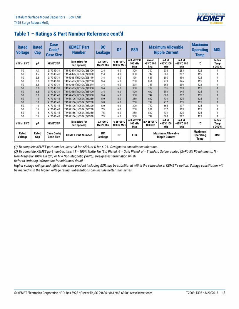
Table 1 – Ratings & Part Number Reference cont'd
(1) To complete KEMET part number, insert M for ±20% or K for ±10%. Designates capacitance tolerance.(2) To complete KEMET part number, insert T = 100% Matte Tin (Sn) Plated, G = Gold Plated, H = Standard Solder coated (SnPb 5% Pb minimum), N = Non-Magnetic 100% Tin (Sn) or M = Non-Magnetic (SnPb). Designates termination finish.Refer to Ordering Information for additional detail.Higher voltage ratings and tighter tolerance product including ESR may be substituted within the same size at KEMET's option. Voltage substitution will be marked with the higher voltage rating. Substitutions can include better than series.
Rated Voltage
Rated Cap
Case Code/
Case Size
KEMET Part Number
DC Leakage DF ESR Maximum Allowable
Ripple Current
Maximum Operating
TempMSL
VDC at 85°C µF KEMET/EIA (See below forpart options)
µA +20°CMax/5 Min
% at +20°C120 Hz Max
mΩ at 20°C100 kHz
Max
mA at +25°C 100
kHz
mA at +85°C 100
kHz
mA at +125°C 100
kHz °C
Reflow Temp
≤ 260°C35 10 D/7343-31 T495D106(1)035A(2)E250 3.5 6.0 250 775 698 310 125 135 10 D/7343-31 T495D106(1)035A(2)E260 3.5 6.0 260 760 684 304 125 135 10 D/7343-31 T495D106(1)035A(2)E300 3.5 6.0 300 707 636 283 125 135 10 D/7343-31 T495D106(1)035A(2)E1K0 3.5 6.0 1000 387 348 155 125 135 10 V/7343-20 T495V106(1)035A(2)E600 3.5 6.0 600 456 410 182 125 135 10 X/7343-43 T495X106(1)035A(2)E175 3.5 6.0 175 971 874 388 125 135 10 X/7343-43 T495X106(1)035A(2)E200 3.5 6.0 200 908 817 363 125 135 10 X/7343-43 T495X106(1)035A(2)E250 3.5 4.0 250 812 731 325 125 135 10 X/7343-43 T495X106(1)035A(2)E260 3.5 4.0 260 797 717 319 125 135 15 C/6032-28 T495C156(1)035A(2)E350 5.3 6.0 350 561 505 224 125 135 15 D/7343-31 T495D156(1)035A(2)E225 5.3 6.0 225 816 734 326 125 135 15 D/7343-31 T495D156(1)035A(2)E260 5.3 6.0 260 760 684 304 125 135 15 D/7343-31 T495D156(1)035A(2)E300 5.3 6.0 300 707 636 283 125 135 15 X/7343-43 T495X156(1)035A(2)E200 5.3 6.0 200 908 817 363 125 135 15 X/7343-43 T495X156(1)035A(2)E225 5.3 6.0 225 856 770 342 125 135 15 X/7343-43 T495X156(1)035A(2)E250 5.3 6.0 250 812 731 325 125 135 15 X/7343-43 T495X156(1)035A(2)E260 5.3 6.0 260 797 717 319 125 135 22 D/7343-31 T495D226(1)035A(2)E125 7.7 6.0 125 1095 986 438 125 135 22 D/7343-31 T495D226(1)035A(2)E200 7.7 6.0 200 866 779 346 125 135 22 D/7343-31 T495D226(1)035A(2)E250 7.7 6.0 250 775 698 310 125 135 22 D/7343-31 T495D226(1)035A(2)E260 7.7 6.0 260 760 684 304 125 135 22 D/7343-31 T495D226(1)035A(2)E300 7.7 6.0 300 707 636 283 125 135 22 X/7343-43 T495X226(1)035A(2)E125 7.7 6.0 125 1149 1034 460 125 135 22 X/7343-43 T495X226(1)035A(2)E130 7.7 6.0 130 1127 1014 451 125 135 22 X/7343-43 T495X226(1)035A(2)E180 7.7 6.0 180 957 861 383 125 135 22 X/7343-43 T495X226(1)035A(2)E200 7.7 6.0 200 908 817 363 125 135 22 X/7343-43 T495X226(1)035A(2)E260 7.7 6.0 260 797 717 319 125 135 22 X/7343-43 T495X226(1)035A(2)E275 7.7 6.0 275 775 698 310 125 135 22 X/7343-43 T495X226(1)035A(2)E300 7.7 6.0 300 742 668 297 125 135 33 D/7343-31 T495D336(1)035A(2)E200 11.6 6.0 200 866 779 346 125 135 33 D/7343-31 T495D336(1)035A(2)E300 11.6 6.0 300 707 636 283 125 135 33 X/7343-43 T495X336(1)035A(2)E100 11.6 6.0 100 1285 1157 514 125 135 33 X/7343-43 T495X336(1)035A(2)E175 11.6 6.0 175 971 874 388 125 135 33 X/7343-43 T495X336(1)035A(2)E250 11.6 6.0 250 812 731 325 125 135 33 X/7343-43 T495X336(1)035A(2)E260 11.6 6.0 260 797 717 319 125 135 33 E/7360-38 T495E336(1)035A(2)E200 11.6 6.0 200 1000 900 400 125 135 47 X/7343-43 T495X476(1)035A(2)E185 16.5 8.0 185 944 850 378 125 135 47 X/7343-43 T495X476(1)035A(2)E200 16.5 8.0 200 908 817 363 125 135 47 X/7343-43 T495X476(1)035A(2)E230 16.5 8.0 230 847 762 339 125 135 47 X/7343-43 T495X476(1)035A(2)E300 16.5 8.0 300 742 668 297 125 150 1 C/6032-28 T495C105(1)050A(2)E1K3 0.5 4.0 1300 291 262 116 125 150 1 C/6032-28 T495C105(1)050A(2)E1K6 0.5 4.0 1600 262 236 105 125 150 2.2 D/7343-31 T495D225(1)050A(2)E600 1.1 6.0 600 500 450 200 125 150 3.3 D/7343-31 T495D335(1)050A(2)E700 1.7 6.0 700 463 417 185 125 150 4.7 D/7343-31 T495D475(1)050A(2)E275 2.4 6.0 275 739 665 296 125 1
VDC at 85°C µF KEMET/EIA (See below forpart options)
µA +20°CMax/5 Min
% at +20°C120 Hz Max
mΩ at 20°C100 kHz
Max
mA at +25°C 100 kHz
mA at +85°C 100
kHz
mA at +125°C 100
kHz °C
Reflow Temp
≤ 260°C
Rated Voltage
Rated Cap
Case Code/ Case Size KEMET Part Number DC
Leakage DF ESR Maximum Allowable Ripple Current
Maximum Operating
TempMSL
© KEMET Electronics Corporation • P.O. Box 5928 • Greenville, SC 29606 • 864-963-6300 • www.kemet.com T2009_T495 • 3/20/2018 1818
Tantalum Surface Mount Capacitors – Low ESRT495 Surge Robust MnO2
Table 1 – Ratings & Part Number Reference cont'd
(1) To complete KEMET part number, insert M for ±20% or K for ±10%. Designates capacitance tolerance.(2) To complete KEMET part number, insert T = 100% Matte Tin (Sn) Plated, G = Gold Plated, H = Standard Solder coated (SnPb 5% Pb minimum), N = Non-Magnetic 100% Tin (Sn) or M = Non-Magnetic (SnPb). Designates termination finish.Refer to Ordering Information for additional detail.Higher voltage ratings and tighter tolerance product including ESR may be substituted within the same size at KEMET's option. Voltage substitution will be marked with the higher voltage rating. Substitutions can include better than series.
Rated Voltage
Rated Cap
Case Code/
Case Size
KEMET Part Number
DC Leakage DF ESR Maximum Allowable
Ripple Current
Maximum Operating
TempMSL
VDC at 85°C µF KEMET/EIA (See below forpart options)
µA +20°CMax/5 Min
% at +20°C120 Hz Max
mΩ at 20°C100 kHz
Max
mA at +25°C 100
kHz
mA at +85°C 100
kHz
mA at +125°C 100
kHz °C
Reflow Temp
≤ 260°C50 4.7 D/7343-31 T495D475(1)050A(2)E300 2.4 6.0 300 707 636 283 125 150 4.7 X/7343-43 T495X475(1)050A(2)E300 2.4 4.0 300 742 668 297 125 150 6.8 D/7343-31 T495D685(1)050A(2)E190 3.4 6.0 190 889 800 356 125 150 6.8 D/7343-31 T495D685(1)050A(2)E200 3.4 6.0 200 866 779 346 125 150 6.8 D/7343-31 T495D685(1)050A(2)E275 3.4 6.0 275 739 665 296 125 150 6.8 D/7343-31 T495D685(1)050A(2)E300 3.4 6.0 300 707 636 283 125 150 6.8 D/7343-31 T495D685(1)050A(2)E400 3.4 6.0 400 612 551 245 125 150 6.8 X/7343-43 T495X685(1)050A(2)E300 3.4 6.0 300 742 668 297 125 150 10 X/7343-43 T495X106(1)050A(2)E250 5.0 8.0 250 812 731 325 125 150 10 X/7343-43 T495X106(1)050A(2)E260 5.0 6.0 260 797 717 319 125 150 10 X/7343-43 T495X106(1)050A(2)E300 5.0 6.0 300 742 668 297 125 150 15 X/7343-43 T495X156(1)050A(2)E200 7.5 6.0 200 908 817 363 125 150 15 X/7343-43 T495X156(1)050A(2)E250 7.5 6.0 250 812 731 325 125 150 15 X/7343-43 T495X156(1)050A(2)E300 7.5 6.0 300 742 668 297 125 1
VDC at 85°C µF KEMET/EIA (See below forpart options)
µA +20°CMax/5 Min
% at +20°C120 Hz Max
mΩ at 20°C100 kHz
Max
mA at +25°C 100 kHz
mA at +85°C 100
kHz
mA at +125°C 100
kHz °C
Reflow Temp
≤ 260°C
Rated Voltage
Rated Cap
Case Code/ Case Size KEMET Part Number DC
Leakage DF ESR Maximum Allowable Ripple Current
Maximum Operating
TempMSL
© KEMET Electronics Corporation • P.O. Box 5928 • Greenville, SC 29606 • 864-963-6300 • www.kemet.com T2009_T495 • 3/20/2018 1919
Tantalum Surface Mount Capacitors – Low ESRT495 Surge Robust MnO2
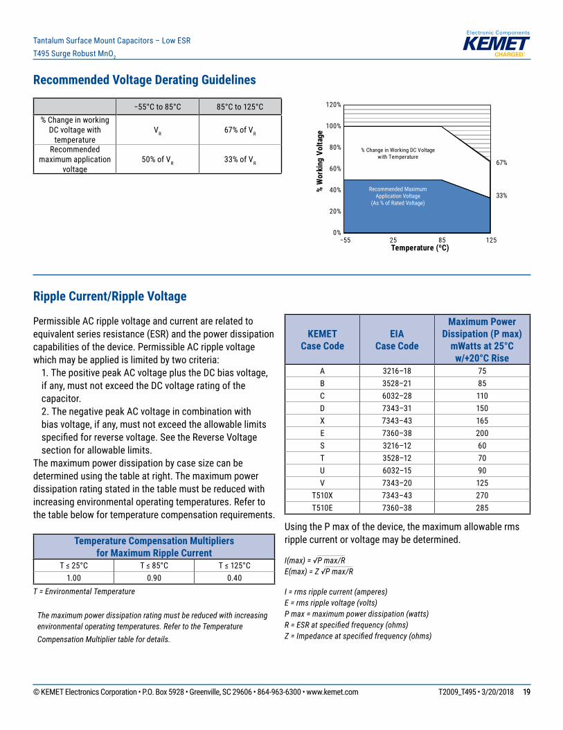
Recommended Voltage Derating Guidelines
−55°Cto85°C 85°Cto125°C% Change in working
DC voltage with temperature
VR 67% of VR
Recommended maximum application
voltage 50% of VR 33% of VR
Ripple Current/Ripple Voltage
Permissible AC ripple voltage and current are related to equivalent series resistance (ESR) and the power dissipation capabilities of the device. Permissible AC ripple voltage which may be applied is limited by two criteria: 1. The positive peak AC voltage plus the DC bias voltage,
if any, must not exceed the DC voltage rating of the capacitor.
2. The negative peak AC voltage in combination with bias voltage, if any, must not exceed the allowable limits specifiedforreversevoltage.SeetheReverseVoltagesection for allowable limits.
The maximum power dissipation by case size can be determined using the table at right. The maximum power dissipation rating stated in the table must be reduced with increasing environmental operating temperatures. Refer to the table below for temperature compensation requirements.
Temperature Compensation Multipliers for Maximum Ripple Current
T≤25°C T≤85°C T≤125°C1.00 0.90 0.40
T = Environmental Temperature
The maximum power dissipation rating must be reduced with increasing environmental operating temperatures. Refer to the Temperature Compensation Multiplier table for details.
KEMET Case Code
EIA Case Code
Maximum Power Dissipation (P max)
mWatts at 25°C w/+20°C Rise
A 3216–18 75B 3528–21 85C 6032–28 110D 7343–31 150X 7343–43 165E 7360–38 200S 3216–12 60T 3528–12 70U 6032–15 90V 7343–20 125
T510X 7343–43 270T510E 7360–38 285
Using the P max of the device, the maximum allowable rms ripple current or voltage may be determined.
I(max) = √P max/RE(max) = Z √P max/R
I = rms ripple current (amperes)E = rms ripple voltage (volts)P max = maximum power dissipation (watts)R = ESR at specified frequency (ohms)Z = Impedance at specified frequency (ohms)
0%
20%
40%
60%
80%
100%
120%
−55 25 85 125
% W
orki
ng V
olta
ge
% Change in Working DC Voltagewith Temperature
Temperature (ºC)
67%
33%Recommended Maximum
Application Voltage(As % of Rated Voltage)

© KEMET Electronics Corporation • P.O. Box 5928 • Greenville, SC 29606 • 864-963-6300 • www.kemet.com T2009_T495 • 3/20/2018 2020
Tantalum Surface Mount Capacitors – Low ESRT495 Surge Robust MnO2
Reverse Voltage
Solid tantalum capacitors are polar devices and may be permanently damaged or destroyed if connected with the wrong polarity.Thepositiveterminalisidentifiedonthecapacitorbodybyastripeplusinsomecasesabevelededge.Asmalldegree of transient reverse voltage is permissible for short periods per the table. The capacitors should not be operated continuously in reverse mode, even within these limits.
Temperature Permissible Transient Reverse Voltage25°C 15% of Rated Voltage85°C 5% of Rated Voltage125°C 1% of Rated Voltage
Table 2 – Land Dimensions/Courtyard
KEMET Metric Size Code
Density Level A: Maximum (Most) Land
Protrusion (mm)
Density Level B: Median (Nominal) Land
Protrusion (mm)
Density Level C: Minimum (Least) Land
Protrusion (mm)Case EIA W L S V1 V2 W L S V1 V2 W L S V1 V2
A 3216–18 1.35 2.20 0.62 6.02 2.80 1.23 1.80 0.82 4.92 2.30 1.13 1.42 0.98 4.06 2.04
B 3528–21 2.35 2.21 0.92 6.32 4.00 2.23 1.80 1.12 5.22 3.50 2.13 1.42 1.28 4.36 3.24
M 3528-15 2.35 2.20 0.92 6.32 4.00 2.23 1.80 1.12 5.22 3.50 2.13 1.42 1.28 4.36 3.24
C 6032–28 2.35 2.77 2.37 8.92 4.50 2.23 2.37 2.57 7.82 4.00 2.13 1.99 2.73 6.96 3.74
U 6032–15 2.35 2.77 2.37 8.92 4.50 2.23 2.37 2.57 7.82 4.00 2.13 1.99 2.73 6.96 3.74
D 7343–31 2.55 2.77 3.67 10.22 5.60 2.43 2.37 3.87 9.12 5.10 2.33 1.99 4.03 8.26 4.84
E1 7360–38 3.25 2.77 3.67 10.22 7.30 3.13 2.37 3.87 9.12 6.80 3.03 1.99 4.03 8.26 6.54
T 3528–12 2.35 2.20 0.92 6.32 4.00 2.23 1.80 1.12 5.22 3.50 2.13 1.42 1.28 4.36 3.24
V 7343–21 2.55 2.77 3.67 10.22 5.60 2.43 2.37 3.87 9.12 5.10 2.33 1.99 4.03 8.26 4.84
X1 7343–43 2.55 2.77 3.67 10.22 5.60 2.43 2.37 3.87 9.12 5.10 2.33 1.99 4.03 8.26 4.84
Density Level A: For low-density product applications. Recommended for wave solder applications and provides a wider process window for reflow solder processes. Density Level B: For products with a moderate level of component density. Provides a robust solder attachment condition for reflow solder processes.Density Level C: For high component density product applications. Before adapting the minimum land pattern variations the user should perform qualification testing based on the conditions outlined in IPC standard 7351 (IPC–7351).¹ Height of these chips may create problems in wave soldering.2 Land pattern geometry is too small for silkscreen outline.
L
S
W W
L
V1
V2
Grid Placement Courtyard
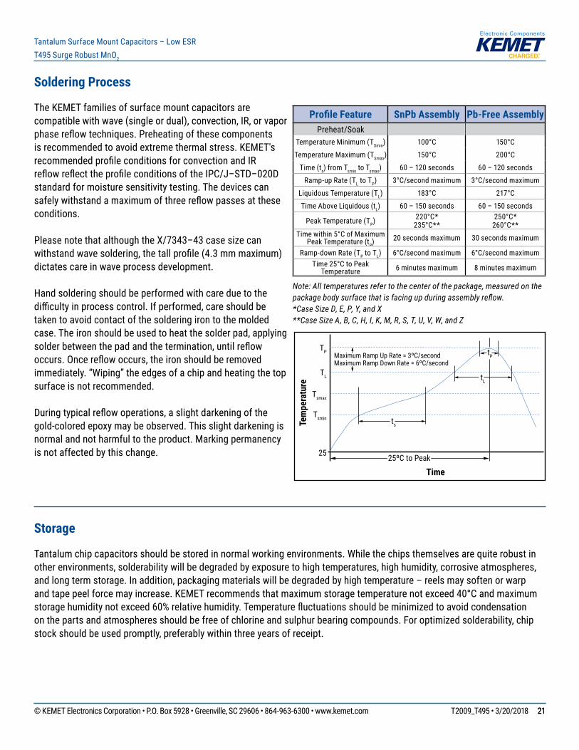
© KEMET Electronics Corporation • P.O. Box 5928 • Greenville, SC 29606 • 864-963-6300 • www.kemet.com T2009_T495 • 3/20/2018 2121
Tantalum Surface Mount Capacitors – Low ESRT495 Surge Robust MnO2
Soldering Process
The KEMET families of surface mount capacitors are compatible with wave (single or dual), convection, IR, or vapor phasereflowtechniques.Preheatingofthesecomponentsis recommended to avoid extreme thermal stress. KEMET's recommendedprofileconditionsforconvectionandIRreflowreflecttheprofileconditionsoftheIPC/J–STD–020Dstandard for moisture sensitivity testing. The devices can safelywithstandamaximumofthreereflowpassesattheseconditions.
Please note that although the X/7343–43 case size can withstandwavesoldering,thetallprofile(4.3mmmaximum)dictates care in wave process development.
Hand soldering should be performed with care due to the difficultyinprocesscontrol.Ifperformed,careshouldbetaken to avoid contact of the soldering iron to the molded case. The iron should be used to heat the solder pad, applying solderbetweenthepadandthetermination,untilreflowoccurs.Oncereflowoccurs,theironshouldberemovedimmediately. “Wiping” the edges of a chip and heating the top surface is not recommended.
Duringtypicalreflowoperations,aslightdarkeningofthegold-colored epoxy may be observed. This slight darkening is normal and not harmful to the product. Marking permanency is not affected by this change.
Profile Feature SnPb Assembly Pb-Free AssemblyPreheat/Soak
Temperature Minimum (TSmin) 100°C 150°C
Temperature Maximum (TSmax) 150°C 200°C
Time (ts) from Tsmin to Tsmax) 60 – 120 seconds 60 – 120 seconds
Ramp-up Rate (TL to TP) 3°C/secondmaximum 3°C/secondmaximum
Liquidous Temperature (TL) 183°C 217°C
Time Above Liquidous (tL) 60 – 150 seconds 60 – 150 seconds
Peak Temperature (TP) 220°C*235°C**
250°C*260°C**
Timewithin5°CofMaximum Peak Temperature (tP) 20 seconds maximum 30 seconds maximum
Ramp-down Rate (TP to TL) 6°C/secondmaximum 6°C/secondmaximumTime25°CtoPeak
Temperature 6 minutes maximum 8 minutes maximum
Note: All temperatures refer to the center of the package, measured on the package body surface that is facing up during assembly reflow. *Case Size D, E, P, Y, and X **Case Size A, B, C, H, I, K, M, R, S, T, U, V, W, and Z
Storage
Tantalum chip capacitors should be stored in normal working environments. While the chips themselves are quite robust in other environments, solderability will be degraded by exposure to high temperatures, high humidity, corrosive atmospheres, and long term storage. In addition, packaging materials will be degraded by high temperature – reels may soften or warp andtapepeelforcemayincrease.KEMETrecommendsthatmaximumstoragetemperaturenotexceed40°Candmaximumstoragehumiditynotexceed60%relativehumidity.Temperaturefluctuationsshouldbeminimizedtoavoidcondensationonthepartsandatmospheresshouldbefreeofchlorineandsulphurbearingcompounds.Foroptimizedsolderability,chipstock should be used promptly, preferably within three years of receipt.
Time
Tem
pera
ture
Tsmin
25
Tsmax
TL
TP Maximum Ramp Up Rate = 3ºC/secondMaximum Ramp Down Rate = 6ºC/second
tP
tL
ts
25ºC to Peak
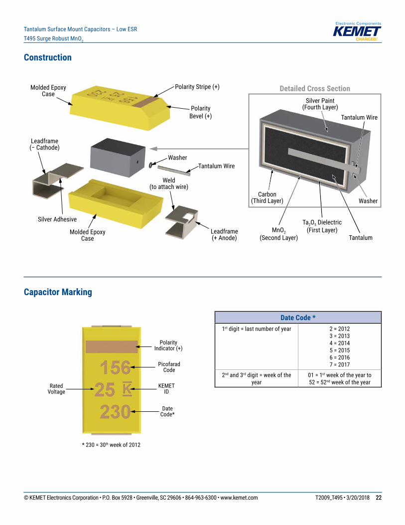
© KEMET Electronics Corporation • P.O. Box 5928 • Greenville, SC 29606 • 864-963-6300 • www.kemet.com T2009_T495 • 3/20/2018 2222
Tantalum Surface Mount Capacitors – Low ESRT495 Surge Robust MnO2
Construction
Leadframe(− Cathode)
Leadframe(+ Anode)
Tantalum Wire
Molded Epoxy Case
Molded Epoxy Case
Polarity Bevel (+)
Weld(to attach wire)
Silver Adhesive
Washer
Polarity Stripe (+) Detailed Cross Section
Tantalum Wire
Tantalum
Ta2O5 Dielectric(First Layer)
Carbon(Third Layer)
Silver Paint(Fourth Layer)
Washer
MnO2(Second Layer)
Capacitor Marking
* 230 = 30th week of 2012
Polarity Indicator (+)
Rated Voltage
Picofarad Code
KEMET ID
Date Code*
Date Code *1st digit = last number of year 2 = 2012
3 = 20134 = 20145 = 20156 = 20167 = 2017
2nd and 3rd digit = week of the year
01 = 1st week of the year to 52 = 52nd week of the year
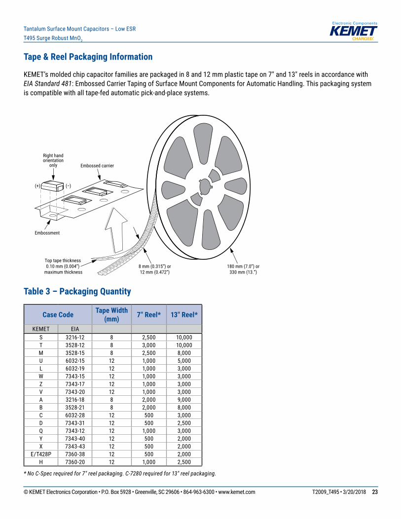
© KEMET Electronics Corporation • P.O. Box 5928 • Greenville, SC 29606 • 864-963-6300 • www.kemet.com T2009_T495 • 3/20/2018 2323
Tantalum Surface Mount Capacitors – Low ESRT495 Surge Robust MnO2
Tape & Reel Packaging Information
KEMET’smoldedchipcapacitorfamiliesarepackagedin8and12mmplastictapeon7"and13"reelsinaccordancewithEIA Standard 481: Embossed Carrier Taping of Surface Mount Components for Automatic Handling. This packaging system is compatible with all tape-fed automatic pick-and-place systems.
Embossment
8 mm (0.315”) or12 mm (0.472”)
Embossed carrier
Right handorientation
only
(+) (−)
Top tape thickness0.10 mm (0.004”)
maximum thickness180 mm (7.0”) or
330 mm (13.”)
Table 3 – Packaging Quantity
Case Code Tape Width (mm) 7" Reel* 13" Reel*
KEMET EIAS 3216-12 8 2,500 10,000T 3528-12 8 3,000 10,000M 3528-15 8 2,500 8,000U 6032-15 12 1,000 5,000L 6032-19 12 1,000 3,000W 7343-15 12 1,000 3,000Z 7343-17 12 1,000 3,000V 7343-20 12 1,000 3,000A 3216-18 8 2,000 9,000B 3528-21 8 2,000 8,000C 6032-28 12 500 3,000D 7343-31 12 500 2,500Q 7343-12 12 1,000 3,000Y 7343-40 12 500 2,000X 7343-43 12 500 2,000
E/T428P 7360-38 12 500 2,000H 7360-20 12 1,000 2,500
* No C-Spec required for 7" reel packaging. C-7280 required for 13" reel packaging.
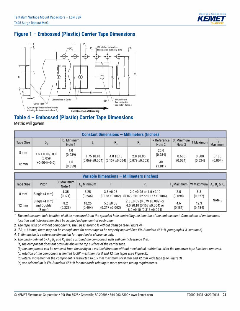
© KEMET Electronics Corporation • P.O. Box 5928 • Greenville, SC 29606 • 864-963-6300 • www.kemet.com T2009_T495 • 3/20/2018 2424
Tantalum Surface Mount Capacitors – Low ESRT495 Surge Robust MnO2
Figure 1 – Embossed (Plastic) Carrier Tape Dimensions
P0
T
F
W
Center Lines of Cavity
A0
B0
User Direction of Unreeling
Cover Tape
K0
B1 is for tape feeder reference only, including draft concentric about B0.
T2
ØD1
ØD0
B1
S1
T1
E1
E2
P1
P2
EmbossmentFor cavity size,see Note 1 Table 4
[10 pitches cumulativetolerance on tape ±0.2 mm]
Table 4 – Embossed (Plastic) Carrier Tape DimensionsMetric will govern
Constant Dimensions — Millimeters (Inches)
Tape Size D0 D1 Minimum
Note 1 E1 P0 P2 R Reference
Note 2S1 Minimum
Note 3 T Maximum T1 Maximum
8 mm 1.5+0.10/−0.0(0.059
+0.004/−0.0)
1.0 (0.039) 1.75 ±0.10
(0.069 ±0.004)4.0 ±0.10
(0.157 ±0.004)2.0 ±0.05
(0.079 ±0.002)
25.0 (0.984) 0.600
(0.024)0.600
(0.024)0.100
(0.004)12 mm 1.5
(0.059)30
(1.181)
Variable Dimensions — Millimeters (Inches)
Tape Size Pitch B1 Maximum Note 4 E2 Minimum F P1 T2 Maximum W Maximum A0, B0 & K0
8 mm Single (4 mm) 4.35 (0.171)
6.25 (0.246)
3.5 ±0.05 (0.138 ±0.002)
2.0 ±0.05 or 4.0 ±0.10(0.079 ±0.002 or 0.157 ±0.004)
2.5 (0.098)
8.3 (0.327)
Note 512 mm
Single (4 mm) and Double
(8 mm)
8.2 (0.323)
10.25 (0.404)
5.5 ±0.05 (0.217 ±0.002)
2.0 ±0.05 (0.079 ±0.002) or4.0 ±0.10 (0.157 ±0.004) or
8.0 ±0.10 (0.315 ±0.004)
4.6 (0.181)
12.3 (0.484)
1. The embossment hole location shall be measured from the sprocket hole controlling the location of the embossment. Dimensions of embossment location and hole location shall be applied independent of each other.
2. The tape, with or without components, shall pass around R without damage (see Figure 4).3. If S1 < 1.0 mm, there may not be enough area for cover tape to be properly applied (see EIA Standard 481–D, paragraph 4.3, section b).4. B1 dimension is a reference dimension for tape feeder clearance only.5. The cavity defi ned by A0, B0 and K0 shall surround the component with suffi cient clearance that: (a) the component does not protrude above the top surface of the carrier tape. (b) the component can be removed from the cavity in a vertical direction without mechanical restriction, after the top cover tape has been removed. (c) rotation of the component is limited to 20° maximum for 8 and 12 mm tapes (see Figure 2). (d) lateral movement of the component is restricted to 0.5 mm maximum for 8 mm and 12 mm wide tape (see Figure 3). (e) see Addendum in EIA Standard 481–D for standards relating to more precise taping requirements.
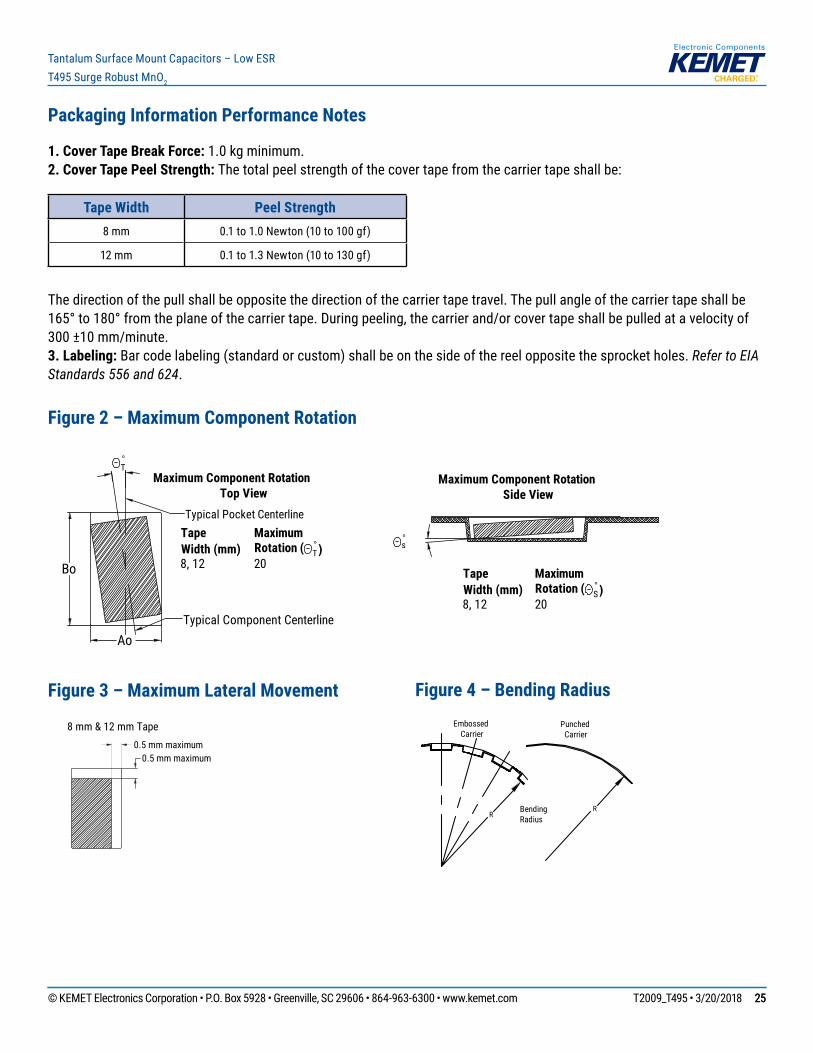
© KEMET Electronics Corporation • P.O. Box 5928 • Greenville, SC 29606 • 864-963-6300 • www.kemet.com T2009_T495 • 3/20/2018 2525
Tantalum Surface Mount Capacitors – Low ESRT495 Surge Robust MnO2
Packaging Information Performance Notes
1. Cover Tape Break Force: 1.0 kg minimum.2. Cover Tape Peel Strength: The total peel strength of the cover tape from the carrier tape shall be:
Tape Width Peel Strength8 mm 0.1 to 1.0 Newton (10 to 100 gf)
12 mm 0.1 to 1.3 Newton (10 to 130 gf)
The direction of the pull shall be opposite the direction of the carrier tape travel. The pull angle of the carrier tape shall be 165°to180°fromtheplaneofthecarriertape.Duringpeeling,thecarrierand/orcovertapeshallbepulledatavelocityof300 ±10 mm/minute.3. Labeling: Bar code labeling (standard or custom) shall be on the side of the reel opposite the sprocket holes. Refer to EIA Standards 556 and 624.
Figure 2 – Maximum Component Rotation
Ao
Bo
°T
°s
Maximum Component RotationTop View
Maximum Component RotationSide View
TapeWidth (mm)
MaximumRotation ( °
T)8, 12 20
TapeWidth (mm)
MaximumRotation (
8, 12 20 °S)
Typical Pocket Centerline
Typical Component Centerline
Figure 3 – Maximum Lateral Movement
0.5 mm maximum0.5 mm maximum
8 mm & 12 mm Tape
Figure 4 – Bending Radius
RRBending
Radius
EmbossedCarrier
PunchedCarrier
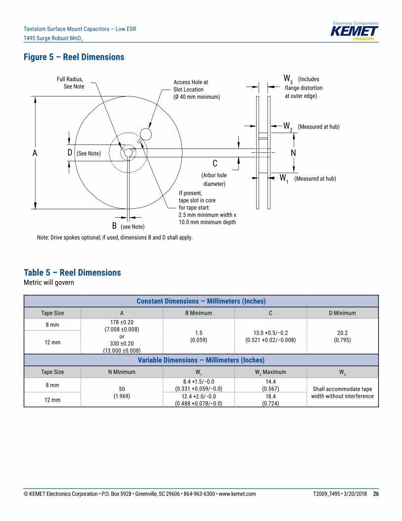
© KEMET Electronics Corporation • P.O. Box 5928 • Greenville, SC 29606 • 864-963-6300 • www.kemet.com T2009_T495 • 3/20/2018 2626
Tantalum Surface Mount Capacitors – Low ESRT495 Surge Robust MnO2
Figure 5 – Reel Dimensions
A D (See Note)
Full Radius,See Note
B (see Note)
Access Hole atSlot Location(Ø 40 mm minimum)
If present,tape slot in corefor tape start:2.5 mm minimum width x10.0 mm minimum depth
W3 (Includes flange distortion at outer edge)
W2 (Measured at hub)
W1 (Measured at hub)
C(Arbor holediameter)
Note: Drive spokes optional; if used, dimensions B and D shall apply.
N
Table 5 – Reel DimensionsMetric will govern
Constant Dimensions — Millimeters (Inches) Tape Size A B Minimum C D Minimum
8 mm 178 ±0.20 (7.008 ±0.008)
or330 ±0.20
(13.000 ±0.008)
1.5 (0.059)
13.0+0.5/−0.2(0.521+0.02/−0.008)
20.2 (0.795)12 mm
Variable Dimensions — Millimeters (Inches) Tape Size N Minimum W1 W2 Maximum W3
8 mm 50 (1.969)
8.4+1.5/−0.0(0.331+0.059/−0.0)
14.4 (0.567) Shall accommodate tape
width without interference12 mm 12.4+2.0/−0.0(0.488+0.078/−0.0)
18.4 (0.724)
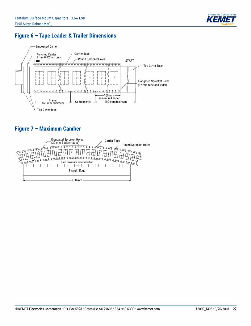
© KEMET Electronics Corporation • P.O. Box 5928 • Greenville, SC 29606 • 864-963-6300 • www.kemet.com T2009_T495 • 3/20/2018 2727
Tantalum Surface Mount Capacitors – Low ESRT495 Surge Robust MnO2
Figure 6 – Tape Leader & Trailer Dimensions
Trailer160 mm minimum
Carrier Tape
END STARTRound Sprocket Holes
Elongated Sprocket Holes(32 mm tape and wider)
Top Cover Tape
Top Cover Tape
Punched Carrier8 mm & 12 mm only
Embossed Carrier
Components
100 mm minimum Leader
400 mm minimum
Figure 7 – Maximum Camber
Carrier TapeRound Sprocket Holes
1 mm maximum, either direction
Straight Edge
250 mm
Elongated Sprocket Holes(32 mm & wider tapes)
© KEMET Electronics Corporation • P.O. Box 5928 • Greenville, SC 29606 • 864-963-6300 • www.kemet.com T2009_T495 • 3/20/2018 2828
Tantalum Surface Mount Capacitors – Low ESRT495 Surge Robust MnO2
KEMET Electronics Corporation Sales Offi ces
Foracompletelistofourglobalsalesoffices,pleasevisitwww.kemet.com/sales.
DisclaimerAllproductspecifications,statements,informationanddata(collectively,the“Information”)inthisdatasheetaresubjecttochange.Thecustomerisresponsibleforchecking and verifying the extent to which the Information contained in this publication is applicable to an order at the time the order is placed.
All Information given herein is believed to be accurate and reliable, but it is presented without guarantee, warranty, or responsibility of any kind, expressed or implied.
StatementsofsuitabilityforcertainapplicationsarebasedonKEMETElectronicsCorporation’s(“KEMET”)knowledgeoftypicaloperatingconditionsforsuchapplications,butarenotintendedtoconstitute–andKEMETspecificallydisclaims–anywarrantyconcerningsuitabilityforaspecificcustomerapplicationoruse.The Information is intended for use only by customers who have the requisite experience and capability to determine the correct products for their application. Any technicaladviceinferredfromthisInformationorotherwiseprovidedbyKEMETwithreferencetotheuseofKEMET’sproductsisgivengratis,andKEMETassumesnoobligation or liability for the advice given or results obtained.
Although KEMET designs and manufactures its products to the most stringent quality and safety standards, given the current state of the art, isolated component failures may still occur. Accordingly, customer applications which require a high degree of reliability or safety should employ suitable designs or other safeguards (suchasinstallationofprotectivecircuitryorredundancies)inordertoensurethatthefailureofanelectricalcomponentdoesnotresultinariskofpersonalinjuryorproperty damage.
Although all product–related warnings, cautions and notes must be observed, the customer should not assume that all safety measures are indicted or that other measures may not be required.
KEMET is a registered trademark of KEMET Electronics Corporation.