Tandon TM848 Specification and Schematic
19
REVISIONS )(2 DESCRIPTION Release ,----------1;,..---- PRODUCT SPECIFICATIONS MODEL NUMBERS TM848·1 AND TM848-2 EIGHT-INCH FLEXIBLE DISK DRIVES, 48 TPI SIGNATURES DR. O'BRIEN CHI( DATE 3/24 'anaon CORPORATION TITLE 1-1NQl--------+---f PRODUCT SPECIFICATIONS "01. INQl MUNRO 3/25 MODEL NUMBERS TM848: AND -2 EIGHT-INCH FLEXIBLE DISK DRIVES, 48 TPI MAJOR 8·80 MAll., SIZE CODE IDlHT NO, owe; NO. A 210069 SCAU 00 NOT SCALI owe
Transcript of Tandon TM848 Specification and Schematic

REVISIONS
)(2
DESCRIPTION
Release
,----------1;,..----
PRODUCT SPECIFICATIONS
MODEL NUMBERS TM848·1 AND TM848-2
EIGHT-INCH FLEXIBLE DISK DRIVES, 48 TPI
SIGNATURES
DR. O'BRIENCHI(
DATE
3/24 'anaonCORPORATION
~ TITLE1-1NQl--------+---f PRODUCT SPECIFICATIONS
"01. INQl MUNRO 3/25 MODEL NUMBERS TM848: AND -2t-----....;.;...;...;...;..;..:..;~--t EIGHT-INCH FLEXIBLE
DISK DRIVES, 48 TPI
MAJOR 8·80
MAll., SIZE CODE IDlHT NO, owe; NO.
A 210069SCAU 00 NOT SCALI owe

1. INTRODUCTION
Tandon Corporation's Model TM848-1 and Model TM848-2 eight-inch flexible disk drives are full-feature drivesthat may be installed in only one-half the space normally required for an eight-inch disk drive. They are compactdata storage devices that use an IBM - formatted Industry Standard eight-inch diskette.
The Model TM848·1 flexible disk drive is capable of reading and writing in single density format on a diskette,using a proprietary read/write head developed and patented by the Tandon Corporation. This disk drive has adouble density capability when a Modified Frequency Modulated (MFM) or other appropriate recording techniqueis used. The encoding and decoding of the data is done by the user's Controller. The Model TM848-2 flexible diskdrive doubles data storage capabilities by utilizing both sides of the diskette.
Track positioning is accomplished by utilizing a metal band driven by a high-speed stepper motor that provides athree (3) millisecond track-to-track step interval.
The use of a DC spindle motor, which may be optionally controlled by the host system, reduces power consumptionand heat dissipation within the disk drive.
1.1 SCOPE OF THE DOCUMENT
This product specification contains the major features, performance specifications, reliability, environmentalspecifications, mechanical specifications and mounting power requirements, interface description, and typicalelectrical interface and timing characteristics of Model TM848-1 and TM848-2 eight-inch flexible disk drives.The TM848-1 disk drive is a forty-eight (48) tracks per inch, single-sided recording device. The TM848-2 diskdrive has the same number of tracks per inch, and is a double-sided recording.
2. MAJOR FEATURES
2.1 WRITE PROTECT (STANDARD)
When a Write Protected diskette is inserted into the flexible disk drive, the write electronics are disabled.
2.2 DAISY CHAIN CAPABILITY (STANDARD)
The disk drive provides Address Selection and Gating functions necessary to daisy chain a maximum of four (4)disk drives at the user's option. The last disk drive on the daisy chain terminates the interface. The terminationsare accomplished by a resistor array plugged into a DIP socket.
2.3 INTERNAL TRIM ERASE (STANDARD)
The flexible disk drive provides the necessary control signals internally for proper trim erasure of data.
The reduced size of the disk drive enables it to occupy only one-half the mounting space required for aconventional drive.
COMPACT SIZE2.4j
II
IIII
I 2.5 DISKETTE LEVER LOCK (OPTIONAL) I'
I The diskette lever lock is controlled by the host system.I~--------~----r-------------"""-'--...----r----:-!, a PRODUCT SPECIFICATIONS . Page 2 !
a n D' n MODEL NUMBERS TM848-1 AND TM848~2 Rev.: X2 , of 14 I. " EIGHT-INCHFLEXfBLE DISK DRIVES !

2.6
2.7
2.8
3.
3.1
3.2
3.3
3.4
3.5
3.6
INDUSTRY STANDARD INTERFACE COMPATIBILITY
The disk drive is compatible with Industry Standard Controllers.
STRAPPABLE OPTIONS
Industry Standard strappable options are available (see Section 10).
ACTIVITY INDICATOR (STANDARD)
An activity indicator, located on the front panel, is automatically illuminated when the flexible disk drive is·selected.
PERFORMANCE SPECIFICATIONS
HEAD WEAR GUARANTEE
Head Wear Guarantee: 15,000 media contact hours
MEDIA AND MEDIA WEAR GUARANTEE
Media: 203.20 mm (8.0 inSh) Industry Standard DisketteWear Guarantee: 3.0 X 10 passes per track, minimum
TRACKS
Number Of Tracks: 77 for TM848-1154 for TM848-2, 77 per surface
Spacing: .529 mm (20.8 milinches)
Inside Track Radius:51.50 mm (2.03 inches), Side 0, both models49.42 mm (1.95 inches), Side 1, TM848-2 only
ACCESS TIMES
Track-To-Track: 3 millisecondsHead Settling Time: 15 millisecondsAverage Access Time, including head settling time: 91 milliseconds
DISK ROTATIONAL SPEED
Motor Start Time: 0.7 second, maximumAverage Latency, including seek and disk travel: 83 millisecondsDisk Rotational Speed: 360 RPMInstantaneous Speed Variation (ISV).: .± 1.25%
RECORDING CAPACITY AND METHOD
Flux Changes Per Inch, Inside Track:6536 FCI, Side 0, both models6816 FCI, Side 1, TM848-2 only
Transfer Rate:250K Bits per second, single density500K Bits per second, double density
'anaanPRODUCT SPECIFICATIONSMODEL NUMBERS TM848-1 AND TM848-2EIGHT-INCH FLEXIBLE DISK DRIVES
Rev. X2Page 3 .of 14

3.7
4.
4.1
4.2
4.3
4.4
4.5
5.
Unformatted Recording Capacity:0.8 MBytes per disk, single density1.6 MBytes per disk, double density
IBM Format Recording Capacity:0.6 MBytes, single density1.2 MBytes, double density
Recording Method:FM, Single DensityMFM, Double Density
ELECTROMAGNETIC CHARACTERISTICS
Tandon Corporation's Model TM848-1 and Model TM848-2 eight-inch flexible disk drives are designed tominimize electrical interference generated internally, propagated through space or on associated conductors.
RELIABILITY
ERROR RATES
Soft Read Errors: 1 in 109 bitsHard Read Errors: 1 in 1012 bitsSeek Errors: 1 in 106
MEAN TIME BEFORE FAILURE
MTBF:10,000 power-on hours
MEAN TIME TO REPAIR
MTTR: 30 minutes
PERIODIC MAINTENANCE
Typical Periodic Maintenance: Every 10,000 power-on hours (see Maintenance Schedule, OEM manual).
COMPONENT LI FE
Average Component Life: 15,000 power-on hours
ENVIRONMENTAL SPECIFICATIONS
The disk drive has been designed to meet its operational specifications under the environmental conditions listedon the next page.
'anaon PRODUCT SPECIFICATIONS Page 4MODEL NUMBERS TM848·1 AND TM848-2 Rev. X2
of 14EIGHT- INCH FLEXIBLE DISK DRIVES
lJ

5.1
,-----.---
I-
---------_.__._-_._------- ---
TEMPERATURE
I
Ii
IIII
5.2
5.3
Operating Temperature: 440 C to 460 C (400 F to 1150 F)Storage Temperature: -400 C tot1 0 C (-400 F to 1600 F)Wet Bulb Temperature: 260 C (780 F) maximum
RELATIVE HUMIDITY
Operating (Noncondensing): 20% ,-- 80%
ALTITUDE
Operating or nonoperating, altitude: From 304.8 meters (1000 feet) below sea level to 15,240 meters (50,000 feet)above sea level.
5.4 SHIPMENT
When prepared for shipment by Tandon Corporation, the eight-inch flexible disk drive will meet the requirementsof NSTA Pre-Shipment Test Procedure Project 1A.
6.
6.1
6.2
7.
7.1
MECHANICAL SPECIFICATIONS AND MOUNTING .
MECHANICAL SPECI FICATIONS
The physical dimensions of Model TM848-1 and Model TM848-2 eight-inch, flexible disk drives are:Height: 58 mm (2.30 inches)Width: 217 mill (8.55 inch_f!s)Length: 337mm (13.25 inches)Weight: 15.4 kg (7 pounds)
MOUNTING
The eight-inch, flexible disk drive may be mounted horizontally or vertically. When mounted horizontally, thecircuit board must be on top.Four 8-32nd tapped mounting holes are provided on the bottom of the disk drive, as are two 8-32nd tappedmounting holes on each side of the disk drive, for attachments to user-supplied mounting brackets (see Figure 1).While four mounting holes are provided for convenience, a three-hole mounting scheme is recommended.
Two drives may be mounted in a single, full-size drive enclosure (4.6" high), using optional mounting brackets.
..._.._........• ---, --
POWER REQUIREMENTS
DC POWER SEQUENCING
A maximum of 0.7 second is required from the time power is applied to the disk drive until a command can beaccepted.
- --.- .... -----~_.. - ------
'anaonPRODUCT SPECIFICATIONSMODEL NUMBERS TM848-1 AND TM848-2EIGHT- INCH FLEXIBLE DISK DRIVES
Rev.X2Page 5of 14
III

8.55 ±D2(217.I",m)
7.50~.o1
(190.5",",)
I,I'IIIIIIII
PCBDI'I
in-\++-+-.,..
Il~~--'-
I Itt--+-----_+_
~======================T===============::=:!==t::::=====::::::::::==::r:=::==~=l=-J:WL-..i..-----+--J..l--- 3.50~.o1 I U 1.00~.OI L____-+ (_88_.9_"'_m) 1 _--1T:(25.4. ",...) .52~.OI
_--------I3.I2.5~.OZ' (13.2m m)(330.2 mm) .20='.02
(5.0 '" "'}
:++-+-----.-I
I
I 2.D7±D2 II: f.60:tjJZ (52.7 ",m) ,
;~L.---__~-.:..,.-----------l..J..+LL.-...:....l111
~-~----B.CO±'oz -------.1-.---"-,....:.:--.80-=-.02(203.2",",) JL (25:4",,,,)
.09tD2(22mm)
FIGURE 1DR1VE OUTLINE DRAWING
TABLE 1
DC Power Connector Pin Assignment
PIN NUMBER DESCR IPTION
123
+24V dc+24V Return+5V Return
4 No connection5 +5V dc6 +5V Return
II
PRODUCT SPECIFICATIONS.
'anaon MODEL NUMBERS TM848-1 AND TM848-2 Rev.: X2Page 6
EIGHT- INCH FLEXIBLE DISK DRIVES of 14

7.2
7.3
8.
8.1
PRIMARY POWER
Standard Operation:Voltage: +24V dc ±.10%Selected Motor On: 1.2 amps typicalDeselecrect:---o:l--amp-- --typiCa1Spindle Motor: 0.5 amps typical
Voltage: +5V dc ±.5%Selected Motor On: 1.0 amp typical
DC POWER CONNECTOR
DC power is supplied to the eight-inch, flexible disk drive through a six-pin AMP connector, Part Number 1-480271-0,connected to the circuit board. The mating connector, AMP Part Number1-480270-0, utilizes AMP contactPart Number 60619-1. Pin assignments are found in Table 1.
The chassis should be connected to earth ground to ensure proper operation.
INTERFACE DESCRIPTION
The I/O is an industry-compatible interface. The connector is a 50-pin edge card connector.
All output lines are TTL compatible open collector, which are terminated in the host system. Input lines utilizeSchmitt trigger type inverters terminated with 150 ohms to +5V dc
Table 2 shows all drive interface lines and pin connections. Maximum cable length is three meters (ten feet) ofribbon or twisted pair. cable.
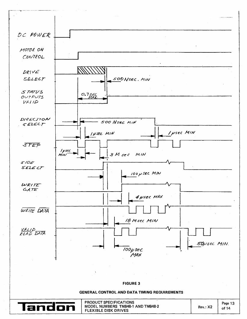
Figure 3 shows interface timing relationships for the signals discussed below (see Section 9).
INPUT (CONTROLLER-TO-DISK DRIVE) LINES
There are twelve (12) input lines, eleven (11) of which are standard and one (1) of which is a strappable feature.
There are two kinds of input signals: those multiplexed in a multiple drive system and those which are not.
The input signals not multiplexed include:
1. Motor Off Control
2. Drive Select 1
3. Drive Select 2
4. Drive Select 3
5. Drive Select 4
'anaonPRODUCT SPECIFICATIONSMODEL NUMBERS TM848-1 AND TM848-2EIGHT-INCH FLEXIBLE DISK DRIVES
Rev. X2Page 7of 14

TABLE 2
DRIVE INTERFACE LINES AND PIN CONNECTIONS
GROUND PIN NUMBER SIGNAL
2 Write Current Switch
3 4 Alternate Input/Output (I/O)
5 6 Motor Off Control
7 8 Alternate I/O
9 10 Two Sided (Strappable) (Model TM8484-2 only) I
I11 12 Disk Change (Strappable)
13 14 Side Select (Model TM848-2 only) I15 16 Activity Indicator (Str~ppable) l ,
17 18 Not used
19 20 Index
21 22 Ready
23 24 Alternate I/O
25 26 Drive Sel.ect 1 (Side Select Option, TM848-2 only)
27 28 Drive Select 2 (Side Select Option, TM848-2 only)
29 30 Drive Select 3 (Side Select Option, TM848-2 only)I
i31 32 Dtive Select 4 (Side Select Option, TM848-2 only)
II
I 33 34 Direction Select (Side Select Option, TM848-2 only)
I.35 36 Step I
I
37 38 Write Data I
39 40 Write Gate
41 42 Track 00
43 44 Write Protect
45 46 Read Data
47 48 Alternate I/O
49 50 Alternate I/O
II
'anaanPRODUCT SPECIFICATIONS Page 8MODEL NUMBERS TM848-1 AND TM848-2 Rev.:X2EIGHT-INCH FLEXIBLE DISK DRIVES of 14

The input signals to be multiplexed include:
1. Step
2. Direction Select
3. Write Gate
4. Write Data
5. Activity Indicator (Strappable)
6. Write Current Switch
7. Side Select (Model TM848·2 only)
8.1.1 MOTOR OFF CONTROL
The motor control lead is used to turn off the spindle motor. When the signal line logic level goes true (low), thedrive's spindle stops. When the Motor Off Control logic level goes false (high), the drive's spindle accelerates to aspeed of 360 RPM, and stabilizes at this speed within a maximum of 0.7 of a second.
8.1.2 DRIVE SELECT
When activated to a true (low) level, Drive Select activates the disk drive electronics, loads the Read/Write head,and readies the drive to respond to Step. Read or Write commands. Four separate input lines - . Drive Select 1,Drive Select 2, Drive Select 3, and Drive Select 4 - - are provided so up to four disk drives can be multiplexedin a system. The address of each disk drive is determined by a select shunt on the signal circuit board.
NOTES
The Drive Select line must remain stable at the logical true (low) level until.a Step, Read, or Write command iscompleted.
Only one Drive Select line can be at a logical true (low) level at a time.
8.1.3 STEP
The Step interface signal causes the Read/Write head assembly to move in the direction of motion defined by theDirection Select line. After the disk drive is selected, a true (low) pulse initiates the access motion on the trailingedge of the Step pulse.
NOTE
The time period between consecutive trailing edges of Step pulses should be no less than three (3) milliseconds.
8.1.4 DIRECTION SELECT
I The Direction Select interface signal determines the direction of motion of the Read/Write head assembly whenI . the Step line is pulsed. The ReadlWrite head assembly moves toward the center of the disk when the Direction
I a PRODUCT SPECIFICATIONSI 'an· D n MODEL NUMBERS TM848-1 AND TM848-2 Rev.:X2I . EIGHT-INCH FLEXIBLE DISK DRIVES
Page 9of 14

,----------------------------------------------------_.-"-
Select line is at the logical true (low) level and a Step pulse is issued. Conversely, the Read/Write head assemblymoves away from the center of the disk when the Direction Select line is at the logical false (high) level and aStep pulse is issued.
NOTE
To ensure correct positioning, the Direction Select line should be stable one (1) mircosecond prior to the trailingedge of the Step pulse. It should remain stable for one (1) mircosecond after the Step pulse.
The drive electronics ignore Step pulses when one of the conditions listed below exists:
1. The Write Gate signal is true (low).
2. The disk drive is not selected.
8.1.5 WRITE GATE
When this signal is in a true (low) state, the write electronics are enabled for writing data on the diskette. The readelectronics are disabled. The Write Gate signal turns on write current in the Read/Write head assembly. Data iswritten under the control of the Write Data input line and the Side Select input line. When the Write Gate line islogical one, the write electronics are disabled.
NOTES
Changes of state of the Write Gate line should occur before the first Write Data pulse.
When a write-protected diskette is installed, the write electronics are disabled.
8.1.6 WRITE DATA
The Write Data interface line is enabled by Write Gate being active. The Write Data line provides the data to bewritten on the diskette. Each transition from a logical one to a logical zero level causes the current passing throughthe Read / Write head assembly to be reversed, resulting in a data bit being written on the diskette.
8.1.7 ACTIVITY INDICATOR
This strappable feature illuminates the Activity Indicator when activated to a logical zero level.
8.1.8 WRITE CURRENT SWITCH
A logical zero (low) signal initiates the lower value of Write Current for writing on Tracks 43 through 76. Conversely,a logical one (high) signal allows use of a higher value of write current for Tracks°through 42.
8.1.9 SIDE SELECT
The side Select interface line is available only on Tandon's Model TM848-2. It defines which side of a two-sideddiskette is to be used for reading or writing. An open circuit or logical one selects the Read/Write head on theSide 0 surface of the diskette. A true (low) selects the Read/Write head on the Side 1 surface of the diskette. When I
I Sw_it_c_h_in_g_f_ro_m_o_n_e_he_a_d,...t_o_t_h_e_o_t_h_e_r,_a_lo_o_m_i_c_ro_s_e_co_n_d_d_e_la_y_i_S_re_q_u_i_re_d_b_e_f_o_re_a_nY_r_ea_d_o,...r_w_r_it_e_o_p_e_ra_t_io_n-r-ca_n ~_ be initiated.
lPRODUCT SPECIFICATIONS, a n a D n MODEL NUMBERS TM848·1 AND TM848·2 Rev.: X2 Page 10 I
. EIGHT-INCH FLEXIBLE DISK DRIVES of 14

8.2 OUTPUT (DISK DRIVE-TO-CONTROLLER) LINES
There are seven (7) output lines, five (5) of which are standard and two (2) of which are strappable features.
The standard output signals are:
1. Read Data
2. Track 00
3. Write Protect
4. Index
5. Ready
The strappable output signals are Disk Change and Two Sided, the latter of which is available only on ModelTM848-2.
8.2.1 READ DATA
The Rea-d Data line transmits data to the Controller when the disk drive is selected and not writing. It provides apUlse for each flux transition recorded and detected on the diskette by the drive electronics. Normally, this signalis a logical one level (high); it becomes a Ipgical zero level (low) for the active state. The Read Data output linegoes to a logical zero level (low) for a duration of 200 nanoseconds, ±50 nanoseconds, for each flux changerecorded on the diskette.
8.2.2 TRACK 00
When the disk drive is selected, the Track 00 interface signal indicates. to the Controller that the Read/Write headis positioned at Track 00, the outermost track. This signal remains at a logical zero level (low) until the Read/Writehead assembly is moved away from Track 00. This signal is at a logical one level (high) when the selected diskdrive's ReadlWrite head assembly is not at Track 00.
8.2.3 WRITE PROTECT
The Write Protect signal is provided to indicate to the user a Write Protected diskette is installed. This signal is alogical zero level when the diskette's write protect notch is not covered.
When the Write Protect signal is a logical one level, the write electronics are enabled and write operations can beperformed.
NOTE
Removing the WP strap and installing the NP strap allows the disk drive to write on the disk when the disk is writeprotected. Write Protect status only indicates the write protect status of the diskette, not the configuration of theWP - NP straps.
8.2.4 INDEX
The Index signal pulse is provided once each revolution of the diskette to indicate the logical beginning of a trackto the Controller.
'anaanPRODUCT SPECIFICATIONSMODEL NUMBERS TM848-1 AND TM848-2EIGHT-INCH FLEXIBLE DISK DRIVES
Rev.: X2 Page 11 lof 14

8.2.5 READY
The Ready interface signal indicates that the diskette is rotating at 360 RPM and two (2) index holes have beensensed after a diskette was inserted into the disk drive.
When a single-sided diskette is installed, Ready is active (low) if Side 0 is selected. Ready is false (high) if Side 1is selected on TM848-2. When a two-sided diskette is installed, Ready is active when either side of the diskette isselected on the TM848-2.
8.2.6 DISK CHANGE
This strappable feature provides a true How) signal to the interface when Drive Select is activated if the disk drivehas gone from a Ready to a Not Ready condition while deselected. This line is reset on the true-to-false transitionof Drive Select if this disk drive ~as gone to a Ready condition.
8.2.7 TWO SIDED
This option is available only on Tandon's Model TM848-2. This strappable feature indicates that a two-sideddiskette is installed.
9. TYPICAL ELECTRICAL INTERFACE AND TIMING CHARACTERISTICS
Lines between the Controiler and the disk drive have the following characteristics:
True = Vout +0.4V (MAX) @ lout = 48mA(maximum)
False =Vout +2.4V (MIN) (Open collector @ lout =250 uA) (maximum)
Figure 2 contains the electrical interface characteristics. Figure 3 contains the general control and data timingrequirements for Model TM848-1 and TM848-2.
+ 5V
150 OHMS
+ TRUE
r --------1: I
DRIVER
TRANSMISSION LINE
= 10 FEET
RECEIVER
74LS04 OR EQUIVALENT
+ TRUE
L'anaonFIGURE 2
ELECTRICAL INTERFACE CHARACTERISTICS
PRODUCT SPECIFICATIONSMODEL NUMBER TM848-1 AND TM848-2EIGHT-INCH FLEXIBLE DISK DRIVES
Rev.:X2Page 12of 14
-_.._._...._--~. __.-•...... _. __ ._ .._-_. '-'." .
!-'toTOe ON
C()NTfOL
DRII/£
.sE-i-E:C-r
.s TAWSOUTPUTS
VAt Ii)
SODNsec. hlN
O.7,sECMA .
~,vsec MIN
klOOp Sec
;t1AX
500 ·Nse.c M 1,41
kJi!'C MiAl --..l ~f/SU 104/11/
r----------
II~ ~5eCMAX1-------------------,
-U ~MsecMw
j
WRI72::.GAn-
.s-/De
S'£L£cr
WR./IC DATA
D/'2E0-'ON~ £Z-:C.c. r
FIGURE 3
GENERAL CONTROL AND DATA TIMING REQUIREMENTS
PRODUCT SPECIFICATIONSMODEL NUMBERS TM848·1 AND TM848·2FLEXIBLE DISK DRIVES
Rev.: X2Page 13of 14

10. STRAPPABLE OPTIONS
Table 3 contains a list of user-selectable strappable options for Model TM848-1 and TM848-2.
TABLE 3
USER-SELECTABLE STRAPPABLE OPTIONS
TRACE FROM FACTORYDESIGNATOR DESCR IPTION OPEN SHORT
DS1 - DS4 Drive address select pins DS1Z In use from Drive Select XR Ready alternate output pad
IX
I Index alternate output pad XD Alternate input in use XDC Alternate output disk change X25 Alternate output disk two-sided* X
OS Stepper power from Drive Select XOL Diskette Lever (Optional) XRR Radial Ready XRI Radial Index XW.P Inhibit write when Write Protected X1B-4B Side Select option using Drive Select * XS1 - S3 Head Select option S1,S3 52
I
*For Model TM 848-2 only
II
'anaanPRODUCT SPECI FICATIONSMODEL NUMBERS TM848-1 AND TM848-2 Rev.:X2
Page 14
EIGHT - INCH FLEXIBLE DISK DRIVES of 14

o
REVISIONS
DESCRIPTION
2
PROD. R£.LEP-.5E. E.o. 40002.
--- - - --I
IIIIIIIIII
---- -..-J
R97~~-J\AIV__-~-----__oTP J~
+24V~-m; HEADI I LOAD1.
1
: :':lOLE"-JDID
O=-~--JI/\tv--_---,!~I IR9G I . I
L_...JPIO
II
I !:J~p.,_D_LQ~Q Qr:TJ.Q.~
III
IIL _
34
5E..LE..CTIOr--JLOGIC
SIDE. 1-
5
POR+
9 UZ2"':d~"-- ::..D.:..:.\R"__+_'___
L5\4
?R.(C)
SUI:? CD POt/.-L':>04
p~ .. ... . SiPEN+
2. ··HL;=:r-----u~'oz
6
+5V+5V
1':>0R5
D~\
7
+5V
150R4
DSI ~
052 ~
DS::' 19DS", ~
+5V+5V
14
L __-l
PI\ Ir-l -'--p=0;..c::R:=--_f--_-'
e: D' /'/ II I I\CTIVIT'( II I L.E.D.
.-d+7 1
VI I I+Z4~ID: KNO'O I2 D Q 1"5"-- ---. I I LOC.K.
U2~ Z 754Co'2.. I I SOLENOIDiNU5E~Do------------------'-1 74 3 ,I I IDRE>E.I-. + ODL..Q.- ----I Q Co I-lLOFF- I U27 I I
_ _______POR_- (~'C&~t~tc.~ L_P'I2. 1 _~ _HEj:),D LOAD c:,oLENO\D DRIVE£G __
I~O M~ __=~!crl-S........02. 1..':>04
: 1'.03 2. U5 ).!1--------4~+_------1:;,~-r-I2.--..-------=14
I~
':> ~ U~:, 4e04
;,.:HL=D"'-F'-~_-_4__~HLL:.,__-.fl:;:.5------~12"Cf"L=S.-..;02.( xOS US 12-'\~=--- --l
Ht~ G:-ji\5 18"'.....- '""° .)>---...::,'O:>.I2.~--------'-.c.ot_./ (I-IEI'.O LDl>.O)
8
o
,.1
B
c
REFERENCE DESIC:tNC\T\ON~
LAST U~~D
U41 ILS I CliO IGl.2.\ IClC:.~1 I I
_'''Oe--..:..:Tu.>o:::::::",:::;::'I:.=OC=D~~
2'5
--'0 OI~I<.CH"'NGE (i:;]DC
7 !;!?cIO ~R. 07
910
+5
RI4 4:7K..
1
P.R.
+5\:~~~30
-z-....LED 2.
INDEX +15V
Jeo ;1?l 4
U25 !REN)Y+
ll/EADY-
\~E.l)Y +
DR'::>E.\"'-
IN iFF +
ll~E.OY -
P.R. (A.)
SF'lN-
oeo),:.1.........._------""19 po,
U2'5
+sv
II<.'bCD2Cr.IK 1'/0220M5P.R{A)
5P\I\I-
?OR.+
R2>5 (P.R.[~)+5V---oIV'V'--"--.....;:....:..:---e
IK..
R.~\IK..
+5
+5
+5
R71~~o
4701(,RP~
7 RP44:7K.
.....------vpD
7 !!J
+5
VDP---...;a::!.2'V2V1lG;:.~!....--4~~~=!.4'V.70~~!--.....J
RP5 RP!>
r--i.--4~+~V
INOEX 1+""" J Rfl9LED ~ 17
:~r--:-+7~+5V
INDIO'/. 2.+"'; I I R~O
LE.D T '. ')..-1.:::!.5_----.~)I ~I I
I II I
C1 ~+5V
" I I: I~
~~~~I: 2'2\(' <\I I RP2,I II II I
: I
: l Vpo
I II I
""'C:~+5VI II II RP5
~~i~ L_~ "" 5PI
CD
B
c
!=DR!!25E.5:!I..:::.:+I- O~~b------ ....
8 ~U .. C~PA.C\TOR5 A-RE:. \~ N\\C.ROFARt.l.D5 50V.
7. £l.U. INOUCT()R~ ~RE., N\ICRDt\f.NR'Y'.5:t 10%.
(0, AU. RE,5\STOR5 ARE \W Ot\t.I\5 ~ W, t. 5%.5. -0 C>- - '~:)IRf\P OPTION.
4, [J~- SIR~I?OIJT\Ot'-.\UXf\TED IN ~\-\\J\n LJ~.
., W - R,! ';)1:::["01< LlY(:\TlD I\-J ~ESISTO~ \-'~C.K RP\.
l. C>- - 01\1 PI?; UMI,ESS om~v.wl~t oPE.CIFIED.
I. -0'-\:'- -'5'iRr,p j:Y.F ~\('t\ ON c\RC.UI' ~OC\W.
APPLICATION
3
AMAGNETICS CORPORATION
landon
MODEL 545DISKE.TTE DR \ VE
E.LECTRON \C-5.
2
MAll.:FINISH:FIRST USENEXT ASSY
45678
NOTES: UNLESS OTHERWISE SPECIFIED
A

8 7 6 5 4 3 2REVISIONS
DESCRIPTION
PROD. RELE~e>E. E..a. ~ 4000Z-
B
o
c
----- --- ----I
II
I
I
I
r
I
I
II
I
II
II
IIIIIIII
_______ _ __ ..-1
WRI
IAJRZ
ROZ
RO\
/URI
UJRZ
\NT lURT W::>Y-
P9C:<.2.9 r-., UPPER
-i L.-----+---:--M.:r-:-..--t-..:;:'-I!-<:Be~:/::T£ ,I CTI I I
.F-------e-----=--f1""'" ~ R79 I ERA::'E.,- C.RZ"':' !=J~"RASEI,.--~=_u.__p:.*--.J<:"'~l\,o---r--=::.:..::.....:.=-=------~~-*------:=t<1I
754«'2. ~+-SHIELO~
I \; L - J READ/PJRIT£I HEAD AS5Y
III1 _
WRITE ELECTRON\C5
ERASE ELECTRONICS
P.R{C)
~J.CD RR.{C:) L...-+- ---'
+5V
R775.&21<.I~
+5
-- -- -- --
+12V +12.V
R5Co R5.<:lI.SLl K. 47K..1%
R5~
7/bB1%
WRT TRAt-J+
OCo
~--~C
+12.V
R403.9K..
~ U24.<:\ CR\7
oCa RSO """5V\1<.-
+12V
I;:<,.0.7~.gK;
'3 A Q I~_
SLR.
II
b-----lt---- WRrTE.-
\.URPROT-
DR':>E.L+
+5
7 •15010
V::\F §9'~~
-IS
I" '"1502.
J.;'~~E
1\1\ .'}\T.T>--~'-=-I§iiltc.~--·
IIL _
I
I
I
I
I
I
~-IIIIIII
T---
I
I
I
B
o
c
I. *" .. R£.S\'5TOR lOC~TE..O \"-1 RE.'::>\5TOR Ptl-CK RP \
APPLICATION
3
REV
B
landanMAGNETICS CORPORATION
2
fiNISH:FIRST USENEXT ASSY
45678
NOTES: UNLESS OTHERWISE SPECIFIED
A

DESCRIPTION
REVISIONS
E.O. *40002
2
PROD. RELS~
345678
D D
8
c
--lIIIIIIIIIIIIIIIIIII
RIG>!l.09K.I%
-+5V
C34lOOP/'
TP4 TPc..
~1<.'27IK.
R'ZbIK..
,p5
P.R.(A)
IKRIZ-
'K.1<..\\
tSV
-t5V
470R!lO
c~o
220)1
4701<.29
0.001C.IIO
- --,IIIIII
C-¢ ICT I I
IIII
+12.V
READ £LECTROAlIC.:5
+IZV
/-lEAD SELECTION
R591:::21<.;
tl2V
CRI5
-R==t-~CRI-4____+__-I
,--- - - -------
IIIIIIIIIIIII R5e R57
6:,5.\1:. 6.2.'51<...1% \%
I 1l'F.\TE- II :JZ'-;"'.)i'j.0*-...----<_--...
II-IIliNT
V.;J:<.TI eU5Y+
IIII ::>\OE.I-
IL _
B
c
APPLICATION
3
AlandanMAGNETICS CORPORATION
2
PIOI.
DIS TITLE'-1NQt-.....c=.,;.:r--+--I MODEL d48 LJISKETTE
ORI//E ELEel;~ON/{,6
UNLESS OTHERWISE SP£CIFI[C
DI.....StOhSAli!NINcHf.STCUIANClS:.xx :l: AHCUU\II
.xxx :l: :l: In"
~:l: .;_ AU. _ COllNDS
_ll..010
FINISH:FIRST USENEXT AS$Y
45678
NOTES; UNLESS OTHERWISE SPECIFIED
A

8 7 6 5 4 3 2REVISIONS
DESCRIPTION
o
8
c
2
+24V
CIC9
+24V
!:=T',i '0_ ,[)GbI: GoZ..o.
C~7·H I ~'_4-_=-ZHI> 20 W
I II '~>i--I : TIl ~3tG-'._-'-1 4~1)
L_J
eRG>1"I400~(TYP4PL)
+24V
+24V
+Z4V
'* RESISTOR LOCATED ltV S/)ME ,{J~SI,)TORPA (.'Go
+24 V
FINISH:FIRST USE
-1I
IP4
14 U/~(i,>.-:- ....:.I -=4~r::--'l5----4I>--- ...---..--........!.:::q /5 I I ~STEPM0TO'£
..._----<'--r--' ULt-J 2074 B 3 ~ iJJ'ND/IJ" ,
(Typ4PL)PIN~4,5,12,13 G:NO I II ,I IIIII
'1 I-,) >-j--3 STn >:~WTO.IGI+-) >+--5 tiJ/AJ1 )/ \.leT 2
L_J
APPLICATION
3
NEXT ASSY
r/2V/(sIl~
R.~7
4.7K5iTPEIIJ+
DR5EL ~
P.R.(A)
P.R.{A)
4
POR-
TPEl
PO/?-
+Z4V
U9 )=~~-----+-=-:
220~w
~'/2V
C~OKE.~~ -r::;:~~..L'. LI -&4.1<-'1"
R2.
ORS£L+
UlRITE-
L--~ •.• . .__ .__
5
LV
.=D:.:.:'/R:.:-=..+ -..- -"I-'-\5lD
r-------=540~(,-----~=.'
+24V
6
~c rJ
I
TPIO
r------- - - ------ ----+-:---1__IIIIIIIIIIIIIIII
IIIL
RP44:7K..
+5V
IIII
UJRITE
PROTeCT IDle POWER"ICONNECTOR. P7
IWIi!.~O"'- r---' r-' -tSV
+5V I I (§>--+-I--+I~» :5 •I I I I I, lo.O~1 CtJ.9, 22, 23, 25, Z9, 3~ 3~
A.7K., I~ I I ) (TYp 12PL) 42, 43.44 109,
I I [D""-:-:----1IH)'>-i-==---..-----+------....-----=.G/I/,:.::;'O
TR~CK¢ I I I(;' I I ) ce"s, 7(;,~ ~O.WI
WR\TE PROTEC'I I I I I ICTYPZPt...)SE.~oOR. I IT> I I »....,I'-'-I---<~----~-
E.,LE.-CTRON\C5 I L__ ...J L ..JC>C=F PC' POWER.,,~ . CGWNEcrOR
ONLY PAO.5
+5
RP.3470K.
I 2.
TP7
7
22K..RP2
VpD 2. Iv
RP5221<.
8
rJ'ALL 000 •PlN~ Ol\J •51C:!f.jj::l..L.
CO"l"l"-C.iOR@P-~
NOTES: UNLESS OTHERWISE SPECIFIED
.L . _
1- - - -;20- - - - - - - - - --r-, RM
ITRt\CK. 8'~ +5V
I 0 ~ I )-,I-",-~_----,IL..F.O : ): 9ITIZ.~C"~C:)~:~;-----.t5v
(/) I I
I~U~SOk, --4,>-:~...!..I_-_~--.-----~I 'I L_~
IIII P3
r--,
II t4~UJR\1E I I 150
IPRt)TECT / I J
l..E.D. ~
I: /ILUR\\E\\~) :2. +5VPROhCl : I
ISf-N:'Ok I I RP2 7 - ----- - ~~.~:~~~L_J .,., T:'OO\.u V.;.J<J "-I.::'--+-~_-J
"v.. B .-1 CCD-7 ~/. iVpo~
Z2K. 4701(.,RPZ _R~ _
A
8
o
c
8 7 6 5 4 3 2
+12VZ.
REV
REVISIONS
DESCRIPTION
SEE SHEET 1
B
D
c
Q2.0
r-'-t2.4V-----~!J__\7 >IBL\0
I I+\2V2---~2. \41-7>1 Plt-JK-.
220 I
~RI:" 131ZZO >jBLU
I II II II I
1-=- ~5~> IPUR
RI2D 41 >1GRY
ZZO I II 1
I I7 1 I
F---'--':~> I WHI
RIZ4 Go1 I2.20 >ICrRN
I II I
III II >I
YEL
I I (1".~~L COLORS.ReVtRI I TO MeTOR WIRI ..-.:\ ..I I
-~>:ORGI II II Ir-- --+----=9~>IR.ED
III
r----_--+----=~>IBR~L_J
Pc.
RI224.71<..
+12V2
+12V2.
-l-12V2
+C55
-/0;4
+12
cst>.¢, lOAf
3~O
1<129
-C53-O.022.1"f
lOOK,R\2.7
C54O.02.2;A
1..-_-+- ..:..\'-I'+N\'Z.90\
U~% .>I:.:~=------..----:.:'-L_10 _
+12V2.
ZAc..~
Q2.\
.... ,2V2.
5
ULlIM51970l..SPEED COAJTROL(SIP PACK-)
7
R.12.1)iOK.
+IOO).Jf
c<oo ,.......:E>:.L- 4..:..1---,2.
r=-~.....---__,RIZ547K..
5PINDLE.
ADJU5~J;f~T~ g~
RIICD
II<..
12V
2
MTROM+ eM \'t
f+'2VZ
T?"\JCCDI
+5V
RIOI ,OKIK.
C77RI09
O.047pfL-
U~5 ~x>-*-_....-=--l5 ")c):c..=4{-__I-- ~---~'Vif':.=----------J
R\IE>47K..
R\l74.7K.-
POR-
+5V
IR\30IK.
L5
c~T(2.2p f\JC~Z
~2151<.
RCDe5COOK..
+5V
C45 +",apt~
+12 VI('0,\14)
+SV +5V
R7l.101<..
MI;,o::..-l?-+~!---j{'
0.1 ETCHC57U~5
~99
1'50
DR 5£..\..--
Mel§>----_ ~·-'b-__-..---::::3"J~51')14:i--4l- M<J 2cr- --'
DCa
11£) MC~0 0
MC}TOR.OiT MC~
(-=OfF) v 0 0
~tv\C 40
B
0(0
L------------+--..!.l.l" »IO~,--...
+5V
D
U~5
PiLl
G~hC CSWIICH DPE~:) I I +5VD\5\~tTTE [I
LOADE.D I II I1 IZI
l_..J oCa
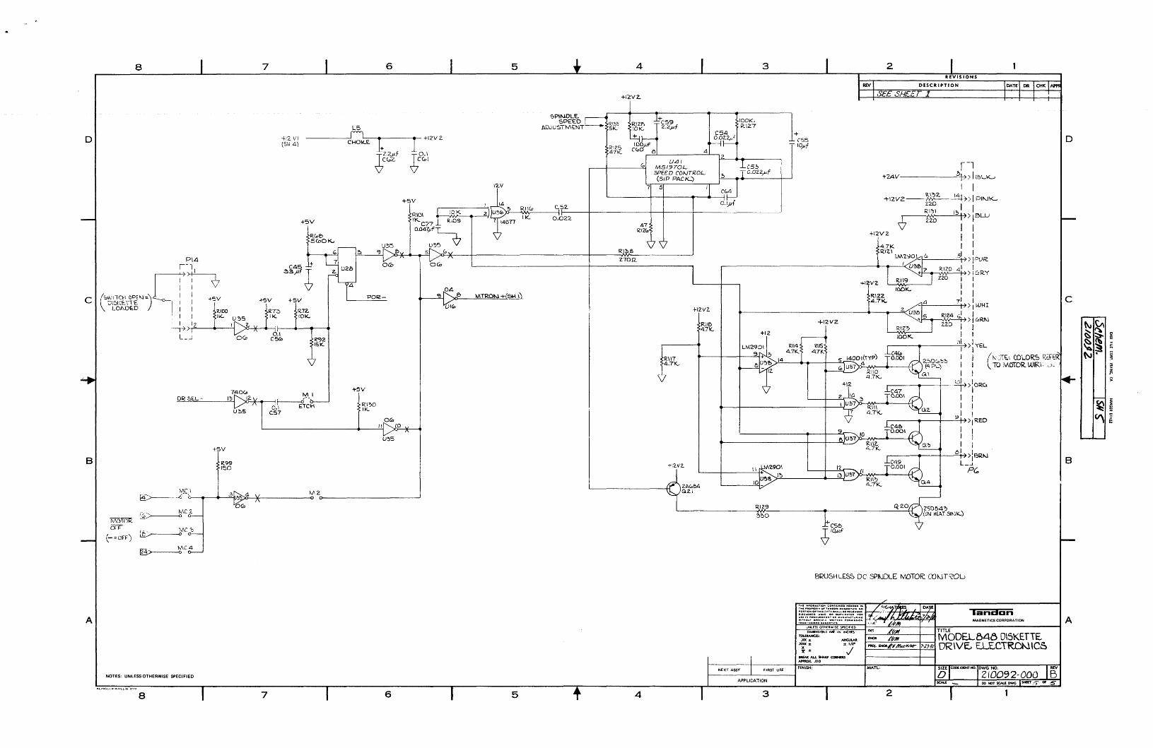
BRUSHLES~ DC SPlk.JDLE tv\OTOR:: COt-JTf?Ol.>
landonA
TOOl' 'N'C T'O.. CO'''A.'''D "'•••ON ••THC ,..0 1''1'' 0' TA"'OOH MAGNeTICI NO..0.TI0 0 .. 1'"1.0·' I. 0DllC:",OII:O ","0 Olll D"'''LIC TIO 1"01tu•• '.....OCli.... IIIOTO.....HU,. C ..U .. , .. O A
t'~~~~~~~~~~Ts:;rcs~;~';;~c;R~~~~:.:rs·~n:·CC;;·I:'iii::;-..o-.~~--=-.,@'!L_-+_-J- M_A_G_NE_T1_CS_C_OR_PO_R_AT_IO_N -IO''''''NS'OhS..,;('NINCHl$ TITLE
~~: ANCUlM I--ENQl---'=--~MODELB48 DISKETTE7: %; 1----<.!..:...:.:.:.:..:..----+7-~;}.=.t81 DR\VE., El...ECTR.O}IJ\C&IIllfAlCALL_CQltNEIlSAPPROX. .Olll
APPLICATION
3
NOTES: UNLESS OTHERWISE SPECIFIED
8 7 6 5 4
NEXT ASSY FIRST USEFINISH:
2
REV
B


![Forces and interactions - NYU Tandon School of Engineeringengineering.nyu.edu/mechatronics/DRK-12/lessons/NGSS-plus-5E/for… · reference, and specification of units.] [Assessment](https://static.fdocuments.net/doc/165x107/5f6c65922d7ea2222370bd9f/forces-and-interactions-nyu-tandon-school-of-en-reference-and-specification-of.jpg)