Tallyman Controller Installation Manual - SEITECNO TALLY MAN CONTROLLER... · The following...
43
TallyMan V1.81 on | Introduction 1 Tallyman Controller Installation Manual USO RESTRITO
Transcript of Tallyman Controller Installation Manual - SEITECNO TALLY MAN CONTROLLER... · The following...

TallyMan V1.81 on | Introduction 1
Tallyman Controller Installation Manual
USO
RES
TRIT
O

TallyMan V1.81 on | Introduction 2
Contents Introduction ............................................................................................................................................ 4
Installation .............................................................................................................................................. 5
TM1 ..................................................................................................................................................... 5
Connections .................................................................................................................................... 5
Pin out details ................................................................................................................................. 6
Default IP ....................................................................................................................................... 10
Initial setup ................................................................................................................................... 10
TM2 ................................................................................................................................................... 13
Connections .................................................................................................................................. 13
Pin out details ............................................................................................................................... 14
Default IP ....................................................................................................................................... 18
Initial setup ................................................................................................................................... 18
TM2+ ................................................................................................................................................. 21
Connections .................................................................................................................................. 21
Pin out details ............................................................................................................................... 22
Default IP ....................................................................................................................................... 28
Initial setup ................................................................................................................................... 28
TMC-1 ................................................................................................................................................ 31
Connections .................................................................................................................................. 31
Pin out details ............................................................................................................................... 32
Default IP ....................................................................................................................................... 34
Initial setup ................................................................................................................................... 34
Specification .......................................................................................................................................... 35
TM1 ................................................................................................................................................... 35
Internal Power Supply Specification .......................................................................................... 35
TM2 ................................................................................................................................................... 36
Internal Power Supply Specification .......................................................................................... 36
TM2+ ................................................................................................................................................. 38
Internal Power Supply Specification .......................................................................................... 38
TMC-1 ................................................................................................................................................ 39
Internal Power Supply Specification .......................................................................................... 39
Motherboard ................................................................................................................................. 40
CPU ................................................................................................................................................ 40
USO
RES
TRIT
O

TallyMan V1.81 on | Introduction 3
Memory ......................................................................................................................................... 40
Disk Drive (Solid state) .................................................................................................................. 40
Safety .................................................................................................................................................... 41
Installation ........................................................................................................................................ 41
Earthing/Grounding ...................................................................................................................... 41
Mounting ....................................................................................................................................... 41
Power ............................................................................................................................................ 41
Ventilation ..................................................................................................................................... 41
EC Declaration of conformity ........................................................................................................ 42
Warranty, Maintenance and Repair ..................................................................................................... 43
Failure during warranty .................................................................................................................... 43
Technical support information ......................................................................................................... 43
TSL Returns Procedure ...................................................................................................................... 43
Fault report details required ......................................................................................................... 43
Packing .......................................................................................................................................... 43
USO
RES
TRIT
O

TallyMan V1.81 on | Introduction 4
Introduction
The following document covers installation of the TSL Tallyman controllers TM1, TM2, TM2+ and
TMC-1.
The TSL tally system consists of a number of displays, either discrete modules or Multiviewers / IMD
(In-Picture-Display); controlled by a 19” 1RU remotely located TallyMan Controller.
The TallyMan Controller distributes power and provides the control for the displays. It also carries
user-defined interfaces for routing matrices, vision mixers and output drivers for cue lights and
additional tally control for cameras etc.
All operational set-ups such as the router assignments, mnemonics and tally routing are
programmed with a set-up computer running another version of TallyMan normally connected to
the Ethernet Port on the TallyMan Controller except in the case of the TMC-1 that is configured
locally.
Back to Top ^
USO
RES
TRIT
O
TallyMan V1.81 on | Installation 5
Installation
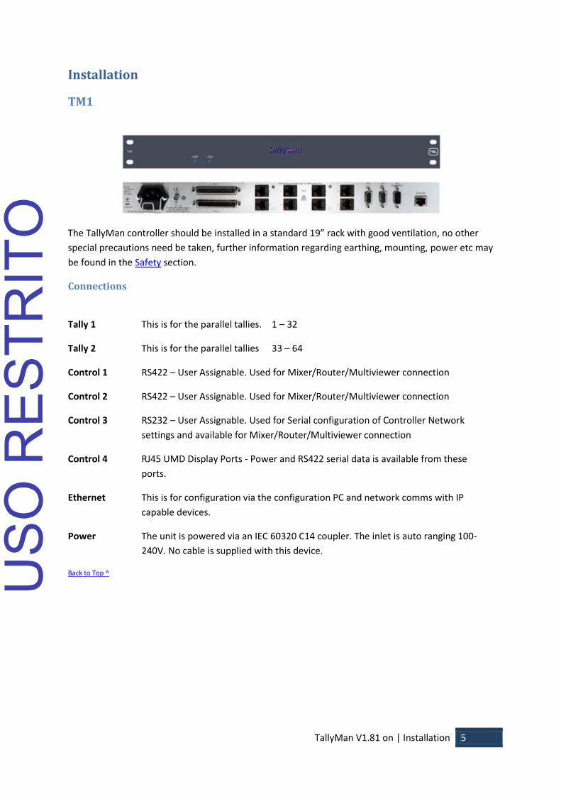
TM1
The TallyMan controller should be installed in a standard 19” rack with good ventilation, no other
special precautions need be taken, further information regarding earthing, mounting, power etc may
be found in the Safety section.
Connections
Tally 1 This is for the parallel tallies. 1 – 32
Tally 2 This is for the parallel tallies 33 – 64
Control 1 RS422 – User Assignable. Used for Mixer/Router/Multiviewer connection
Control 2 RS422 – User Assignable. Used for Mixer/Router/Multiviewer connection
Control 3 RS232 – User Assignable. Used for Serial configuration of Controller Network
settings and available for Mixer/Router/Multiviewer connection
Control 4 RJ45 UMD Display Ports - Power and RS422 serial data is available from these
ports.
Ethernet This is for configuration via the configuration PC and network comms with IP
capable devices.
Power The unit is powered via an IEC 60320 C14 coupler. The inlet is auto ranging 100-
240V. No cable is supplied with this device.
Back to Top ^ USO
RES
TRIT
O

TallyMan V1.81 on | Installation 6
Pin out details
Ethernet
The cable required to connect the TM1 controller with the configuring computer is as follows:
Signal Name RJ-45 Ethernet Pin
Numbers
Crossover Cable
Pinouts
TX + 1 3 TX - 2 6 RX + 3 1
EPWR + Power 4 4 EPWR + Power 5 5
RX - 6 2 EPWR - Power 7 7 EPWR - Power 8 8
For a hub connection, use a straight-through cable. For TallyMan Controller to Computer, use a
crossover cable
Back to Top ^
USO
RES
TRIT
O

TallyMan V1.81 on | Installation 7
Control Ports
Control ports 1 and 2 – Serial RS422
Pin Numbers Signal Pin Numbers Signal
1 0v/Chassis 6 0v
2 TX- 7 TX+
3 RX+ 8 RX-
4 0v 9 0v
5 -
Control Port 3 – Serial RS232 (Maintenance port)
Pin Numbers Signal Pin Numbers Signal
1 - 6 -
2 RX 7 RTS
3 TX 8 CTS
4 DTR 9 -
5 0v
Control Port 4 - Serial RS422 Display Ports
RJ45 DISPLAY CONNECTORS
1 0v
2 0v
3 RX-
4 TX+
5 TX-
6 RX+
7 +24v
8 +24v
The Display ports are wired pin to pin, all 8 display ports are paralleled and are addressed as port 4.
UMD displays should be distributed evenly between the eight display drive outputs on the TM1
controller. Cables to the UMDs should be screened CAT5 cable, in order to conform to European CE
requirements it is recommended that CAT5E FTP cable is used.
Back to Top ^
USO
RES
TRIT
O
TallyMan V1.81 on | Installation 8
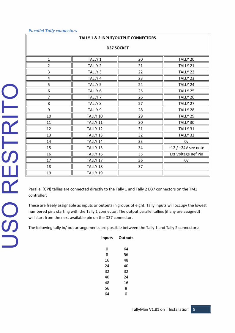
Parallel Tally connectors
TALLY 1 & 2 INPUT/OUTPUT CONNECTORS
D37 SOCKET
1 TALLY 1 20 TALLY 20
2 TALLY 2 21 TALLY 21
3 TALLY 3 22 TALLY 22
4 TALLY 4 23 TALLY 23
5 TALLY 5 24 TALLY 24
6 TALLY 6 25 TALLY 25
7 TALLY 7 26 TALLY 26
8 TALLY 8 27 TALLY 27
9 TALLY 9 28 TALLY 28
10 TALLY 10 29 TALLY 29
11 TALLY 11 30 TALLY 30
12 TALLY 12 31 TALLY 31
13 TALLY 13 32 TALLY 32
14 TALLY 14 33 0v
15 TALLY 15 34 +12 / +24V see note
below 16 TALLY 16 35 Ext Voltage Ref Pin
17 TALLY 17 36 0v
18 TALLY 18 37 -
19 TALLY 19
Parallel (GPI) tallies are connected directly to the Tally 1 and Tally 2 D37 connectors on the TM1
controller.
These are freely assignable as inputs or outputs in groups of eight. Tally inputs will occupy the lowest
numbered pins starting with the Tally 1 connector. The output parallel tallies (if any are assigned)
will start from the next available pin on the D37 connector.
The following tally in/ out arrangements are possible between the Tally 1 and Tally 2 connectors:
Inputs Outputs
0 64
8 56
16 48
24 40
32 32
40 24
48 16
56 8
64 0
USO
RES
TRIT
O
TallyMan V1.81 on | Installation 9
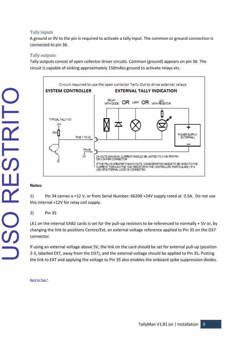
Tally inputs
A ground or 0V to the pin is required to activate a tally input. The common or ground connection is
connected to pin 36.
Tally outputs
Tally outputs consist of open collector driver circuits. Common (ground) appears on pin 36. The
circuit is capable of sinking approximately 150mAto ground to activate relays etc.
Notes:
1) Pin 34 carries a +12 V, or from Serial Number: 66200 +24V supply rated at 0.5A. Do not use
this internal +12V for relay coil supply.
2) Pin 35
LK1 on the internal EAB2 cards is set for the pull-up resistors to be referenced to normally + 5V or, by
changing the link to positions Centre/Ext, an external voltage reference applied to Pin 35 on the D37
connector.
If using an external voltage above 5V, the link on the card should be set for external pull-up (position
2-3, labelled EXT, away from the D37), and the external voltage should be applied to Pin 35. Putting
the link to EXT and applying the voltage to Pin 35 also enables the onboard spike suppression diodes.
Back to Top ^
USO
RES
TRIT
O

TallyMan V1.81 on | Installation 10
Default IP
The default IP parameters of TSL Tallyman controllers are:
IP Address: 10.0.0.220
Subnet Mask: 255.0.0.0
Connection for configuration purposes is via a PC running TallyMan, available for download from the
TSL website www.TSL.co.uk
Initial setup
Connect a PC running a terminal program (Hyper terminal/Putty/Tera Term Pro for example) to the
Maintenance Port, Port 3 on the TallyMan controller.
HyperTerminal Settings
USO
RES
TRIT
O
TallyMan V1.81 on | Installation 11
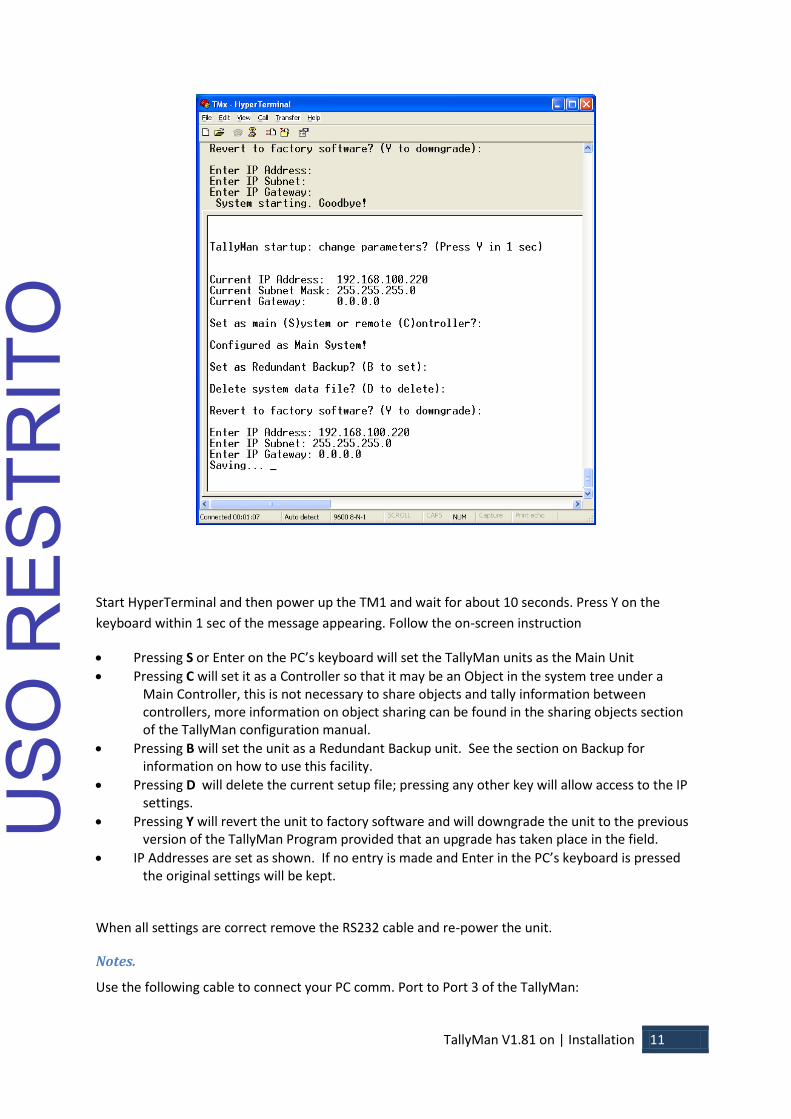
Start HyperTerminal and then power up the TM1 and wait for about 10 seconds. Press Y on the
keyboard within 1 sec of the message appearing. Follow the on-screen instruction
Pressing S or Enter on the PC’s keyboard will set the TallyMan units as the Main Unit
Pressing C will set it as a Controller so that it may be an Object in the system tree under a Main Controller, this is not necessary to share objects and tally information between controllers, more information on object sharing can be found in the sharing objects section of the TallyMan configuration manual.
Pressing B will set the unit as a Redundant Backup unit. See the section on Backup for information on how to use this facility.
Pressing D will delete the current setup file; pressing any other key will allow access to the IP settings.
Pressing Y will revert the unit to factory software and will downgrade the unit to the previous version of the TallyMan Program provided that an upgrade has taken place in the field.
IP Addresses are set as shown. If no entry is made and Enter in the PC’s keyboard is pressed the original settings will be kept.
When all settings are correct remove the RS232 cable and re-power the unit.
Notes.
Use the following cable to connect your PC comm. Port to Port 3 of the TallyMan:
USO
RES
TRIT
O

TallyMan V1.81 on | Installation 12
PC TM1 2 3
3 2
5 5
Back to Top ^
USO
RES
TRIT
O

TallyMan V1.81 on | Installation 13
TM2
The TallyMan controller should be installed in a standard 19” rack with good ventilation, no other
special precautions need be taken, further information regarding earthing, mounting, power etc may
be found in the Safety section.
Connections
Tally 1 This is for the parallel tallies. 1 – 32
Tally 2 This is for the parallel tallies 33-64
Tally 3 This is for the parallel tallies 65-96
Tally 4 This is for the parallel tallies 97-128
Control 1 RS422 – User Assignable. Used for Mixer/Router/Multiviewer connection
Control 2 RS422 – User Assignable. Used for Mixer/Router/Multiviewer connection
Control 3 RS232 – User Assignable. Used for Serial configuration of Controller Network settings
and available for Mixer/Router/Multiviewer connection
Control 4 RJ45 UMD Display Ports - Power and RS422 serial data is available from these ports.
Control 5 RS422 – User Assignable. Used for Mixer/Router/Multiviewer connection
Control 6 RS422 – User Assignable. Used for Mixer/Router/Multiviewer connection
Control 7 RS422 – User Assignable. Used for Mixer/Router/Multiviewer connection
Ethernet This is for configuration via the configuration PC and network comms with IP capable
devices.
Power The unit is powered via an IEC 60320 C14 coupler. The inlet is auto ranging 100-
240V. No cable is supplied with this device.
Back to Top ^
USO
RES
TRIT
O
TallyMan V1.81 on | Installation 14
Pin out details
Ethernet
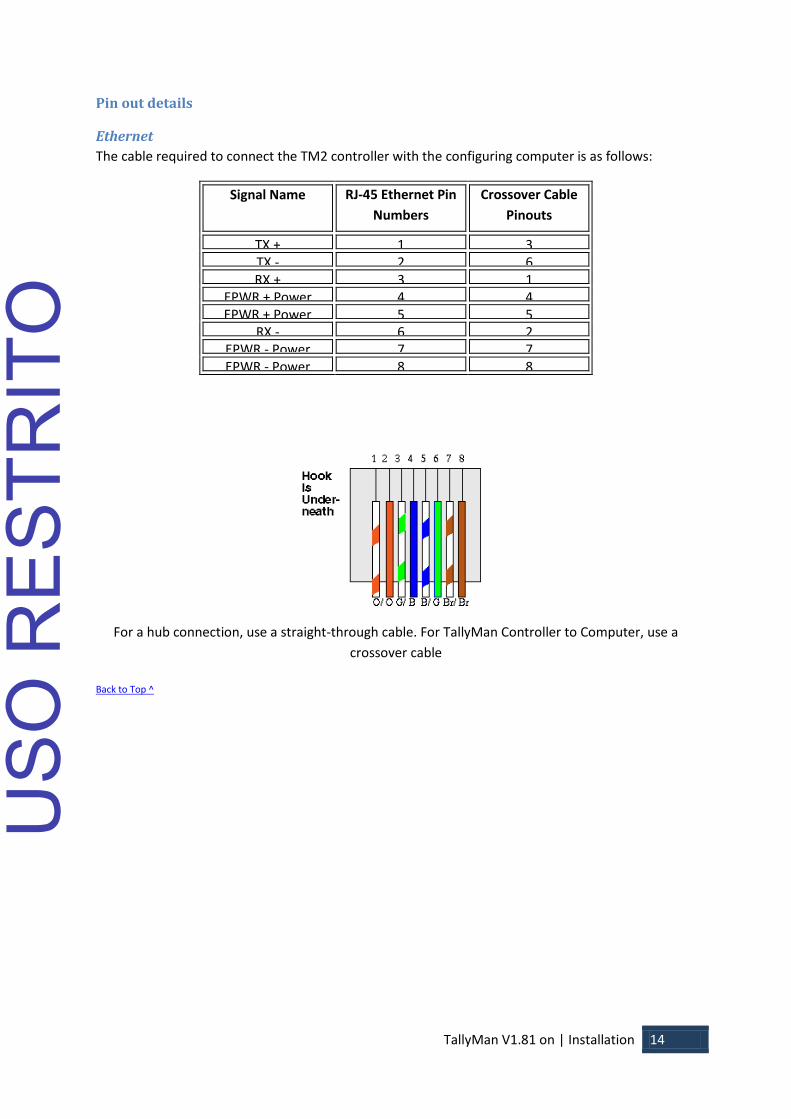
The cable required to connect the TM2 controller with the configuring computer is as follows:
Signal Name RJ-45 Ethernet Pin
Numbers
Crossover Cable
Pinouts
TX + 1 3 TX - 2 6 RX + 3 1
EPWR + Power 4 4 EPWR + Power 5 5
RX - 6 2 EPWR - Power 7 7 EPWR - Power 8 8
For a hub connection, use a straight-through cable. For TallyMan Controller to Computer, use a
crossover cable
Back to Top ^
USO
RES
TRIT
O

TallyMan V1.81 on | Installation 15
Control Ports
Control ports 1,2,5,6 & 7 – Serial RS422
Pin Numbers Signal Pin Numbers Signal
1 0v/Chassis 6 0v
2 TX- 7 TX+
3 RX+ 8 RX-
4 0v 9 0v
5 -
Control Port 3 – Serial RS232 (Maintenance port)
Pin Numbers Signal Pin Numbers Signal
1 - 6 -
2 RX 7 RTS
3 TX 8 CTS
4 DTR 9 -
5 0v
Control Port 4 - Serial RS422 Display Ports
RJ45 DISPLAY CONNECTORS
1 0v
2 0v
3 RX-
4 TX+
5 TX-
6 RX+
7 +24v
8 +24v
The Display ports are wired pin to pin, all 8 display ports are paralleled and are addressed as port 4.
UMD displays should be distributed evenly between the eight display drive outputs on the TM2
controller. Cables to the UMDs should be screened CAT5 cable, in order to conform with European
CE requirements it is recommended that CAT5E FTP cable is used
Back to Top ^
USO
RES
TRIT
O

TallyMan V1.81 on | Installation 16
Parallel Tally connectors
TALLY 1,2,3 & 4 INPUT/OUTPUT CONNECTORS
D37 SOCKET
1 TALLY 1 20 TALLY 20
2 TALLY 2 21 TALLY 21
3 TALLY 3 22 TALLY 22
4 TALLY 4 23 TALLY 23
5 TALLY 5 24 TALLY 24
6 TALLY 6 25 TALLY 25
7 TALLY 7 26 TALLY 26
8 TALLY 8 27 TALLY 27
9 TALLY 9 28 TALLY 28
10 TALLY 10 29 TALLY 29
11 TALLY 11 30 TALLY 30
12 TALLY 12 31 TALLY 31
13 TALLY 13 32 TALLY 32
14 TALLY 14 33 0v
15 TALLY 15 34 +12 / +24V see note
below 16 TALLY 16 35 Ext Voltage Ref Pin
17 TALLY 17 36 0v
18 TALLY 18 37 -
19 TALLY 19
Parallel (GPI) tallies are connected directly to the Tally 1, 2, 3 & 4 D37 connectors on the TM2
controller.
These are freely assignable as inputs or outputs in groups of eight. Tally inputs will occupy the lowest
numbered pins starting with the Tally 1 connector. The output parallel tallies (if any are assigned)
will start from the next available pin on the D37 connector.
The following tally in/out arrangements are possible between the Tally 1 and Tally 2 connectors:
Inputs Outputs
0 64
8 56
16 48
24 40
32 32
40 24
48 16
56 8
64 0
USO
RES
TRIT
O
TallyMan V1.81 on | Installation 17
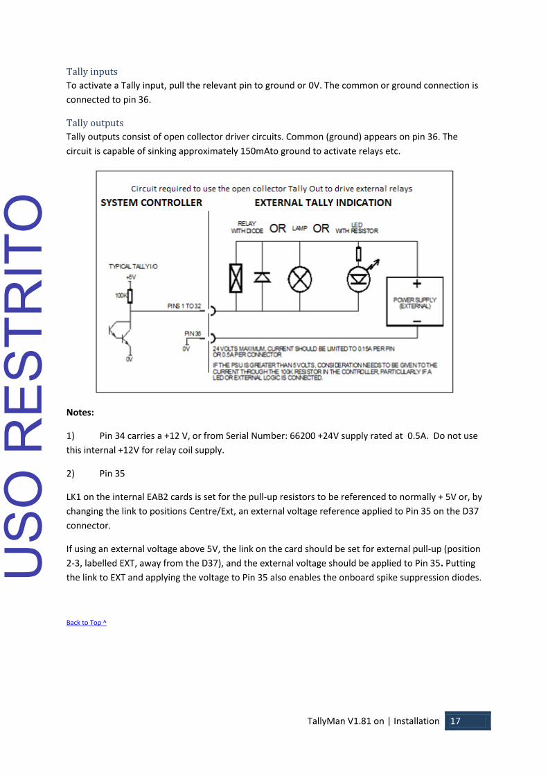
Tally inputs
To activate a Tally input, pull the relevant pin to ground or 0V. The common or ground connection is
connected to pin 36.
Tally outputs
Tally outputs consist of open collector driver circuits. Common (ground) appears on pin 36. The
circuit is capable of sinking approximately 150mAto ground to activate relays etc.
Notes:
1) Pin 34 carries a +12 V, or from Serial Number: 66200 +24V supply rated at 0.5A. Do not use
this internal +12V for relay coil supply.
2) Pin 35
LK1 on the internal EAB2 cards is set for the pull-up resistors to be referenced to normally + 5V or, by
changing the link to positions Centre/Ext, an external voltage reference applied to Pin 35 on the D37
connector.
If using an external voltage above 5V, the link on the card should be set for external pull-up (position
2-3, labelled EXT, away from the D37), and the external voltage should be applied to Pin 35. Putting
the link to EXT and applying the voltage to Pin 35 also enables the onboard spike suppression diodes.
Back to Top ^
USO
RES
TRIT
O
TallyMan V1.81 on | Installation 18
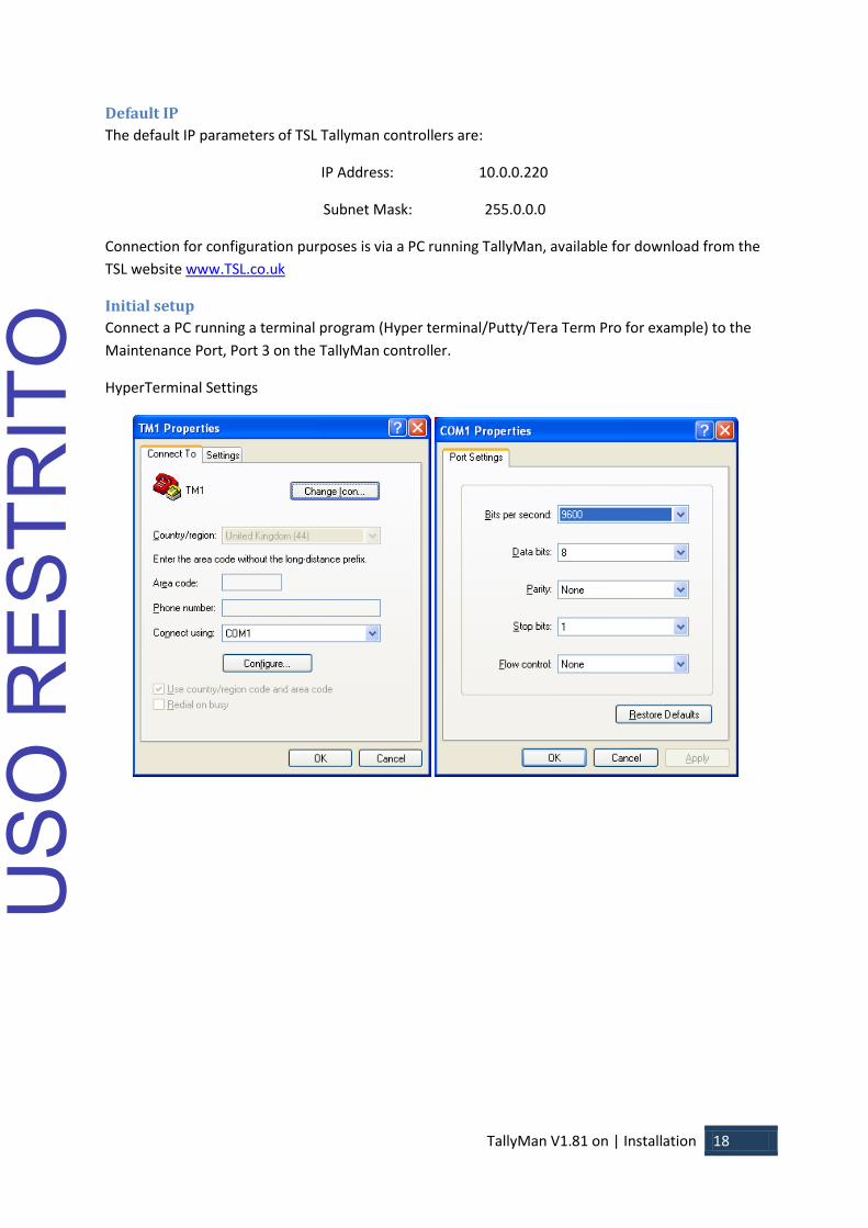
Default IP
The default IP parameters of TSL Tallyman controllers are:
IP Address: 10.0.0.220
Subnet Mask: 255.0.0.0
Connection for configuration purposes is via a PC running TallyMan, available for download from the
TSL website www.TSL.co.uk
Initial setup
Connect a PC running a terminal program (Hyper terminal/Putty/Tera Term Pro for example) to the
Maintenance Port, Port 3 on the TallyMan controller.
HyperTerminal Settings
USO
RES
TRIT
O
TallyMan V1.81 on | Installation 19
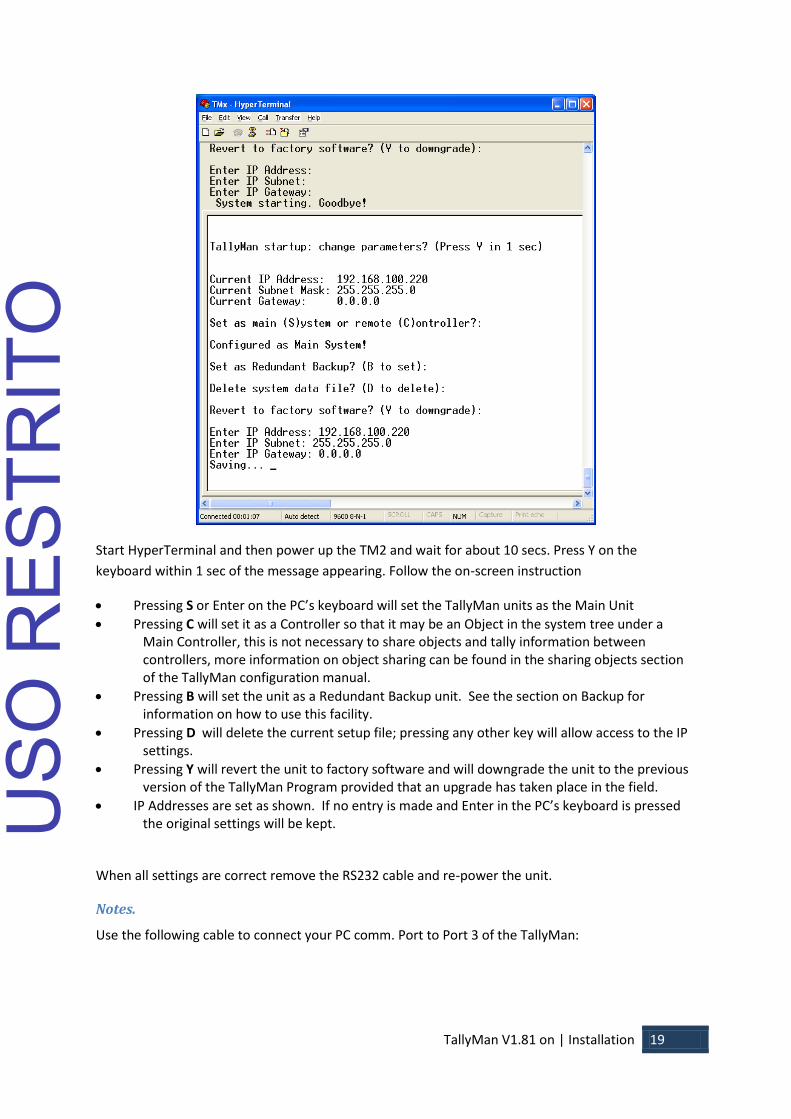
Start HyperTerminal and then power up the TM2 and wait for about 10 secs. Press Y on the
keyboard within 1 sec of the message appearing. Follow the on-screen instruction
Pressing S or Enter on the PC’s keyboard will set the TallyMan units as the Main Unit
Pressing C will set it as a Controller so that it may be an Object in the system tree under a Main Controller, this is not necessary to share objects and tally information between controllers, more information on object sharing can be found in the sharing objects section of the TallyMan configuration manual.
Pressing B will set the unit as a Redundant Backup unit. See the section on Backup for information on how to use this facility.
Pressing D will delete the current setup file; pressing any other key will allow access to the IP settings.
Pressing Y will revert the unit to factory software and will downgrade the unit to the previous version of the TallyMan Program provided that an upgrade has taken place in the field.
IP Addresses are set as shown. If no entry is made and Enter in the PC’s keyboard is pressed the original settings will be kept.
When all settings are correct remove the RS232 cable and re-power the unit.
Notes.
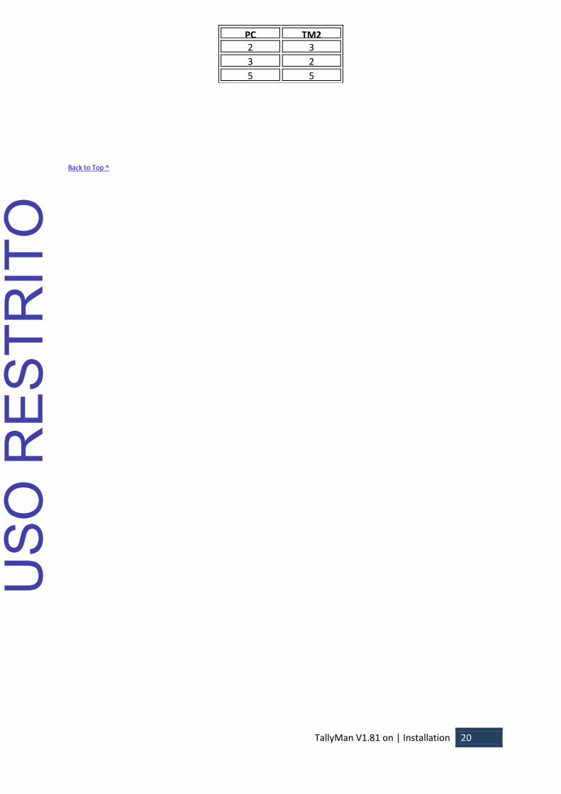
Use the following cable to connect your PC comm. Port to Port 3 of the TallyMan:
USO
RES
TRIT
O
TallyMan V1.81 on | Installation 20
Back to Top ^
PC TM2 2 3
3 2
5 5
USO
RES
TRIT
O

TallyMan V1.81 on | Installation 21
TM2+
The TallyMan controller should be installed in a standard 19” rack with good ventilation, no other
special precautions need be taken, further information regarding earthing, mounting, power etc may
be found in the Safety section.
Connections
Tally 1 This is for the parallel input tallies. 1 – 32
Tally 2 This is for the (isolated relay) parallel output tallies 1-16
Tally 3 This is for the (isolated relay) parallel output tallies 17-32
Tally 4 This is for the (isolated relay) parallel output tallies 33-48
Control 1 RS422 – User Assignable. Used for Mixer/Router/Multiviewer connection
Control 2 RS422 – User Assignable. Used for Mixer/Router/Multiviewer connection
Control 3 RS232 – User Assignable. Used for Serial configuration of Controller Network settings
and available for Mixer/Router/Multiviewer connection
Control 4 RJ45 UMD Display Ports - Power and RS422 serial data is available from these ports.
Control 5 RS422 – User Assignable. Used for Mixer/Router/Multiviewer connection
Control 6 RS422 – User Assignable. Used for Mixer/Router/Multiviewer connection
Control 7 RS422 – User Assignable. Used for Mixer/Router/Multiviewer connection
Control 8 RS422 – User Assignable. Used for Mixer/Router/Multiviewer connection
Ethernet This is for configuration via the configuration PC and network comms with IP capable
devices.
Power The unit is powered via an IEC 60320 C14 coupler. The inlet is auto ranging 100-
240V. No cable is supplied with this device.
Back to Top ^
USO
RES
TRIT
O

TallyMan V1.81 on | Installation 22
Pin out details
Ethernet
The cable required to connect the TM2+ controller with the configuring computer is as follows:
Signal Name RJ-45 Ethernet Pin
Numbers
Crossover Cable
Pinouts
TX + 1 3 TX - 2 6 RX + 3 1
EPWR + Power 4 4 EPWR + Power 5 5
RX - 6 2 EPWR - Power 7 7 EPWR - Power 8 8
For a hub connection, use a straight-through cable. For TallyMan Controller to Computer, use a
crossover cable
Back to Top ^
USO
RES
TRIT
O

TallyMan V1.81 on | Installation 23
Control Ports
Control ports 1,2,5,6, 7 & 8 – Serial RS422
Pin Numbers Signal Pin Numbers Signal
1 0v/Chassis 6 0v
2 TX- 7 TX+
3 RX+ 8 RX-
4 0v 9 0v
5 -
Control Port 3 – Serial RS232 (Maintenance port)
Pin Numbers Signal Pin Numbers Signal
1 - 6 -
2 RX 7 RTS
3 TX 8 CTS
4 DTR 9 -
5 0v
Control Port 4 - Serial RS422 Display Ports
RJ45 DISPLAY CONNECTORS
1 0v
2 0v
3 RX-
4 TX+
5 TX-
6 RX+
7 +24v
8 +24v
The Display ports are wired pin to pin, all 8 display ports are paralleled and are addressed as port 4.
UMD displays should be distributed evenly between the eight display drive outputs on the TM2+
controller. Cables to the UMDs should be screened CAT5 cable, in order to conform with European
CE requirements it is recommended that CAT5E FTP cable is used
Back to Top ^
USO
RES
TRIT
O

TallyMan V1.81 on | Installation 24
Parallel Tally connectors
Parallel (GPI) tallies are connected directly to the Tally 1, 2, 3 & 4 D37 connectors on the TM2+
controller.
Tally inputs
To activate a tally input, pull the relevant pin to ground or 0V. The common or ground connection is
connected to pin 36.
TALLY 1 INPUT CONNECTORS
D37 SOCKET
1 TALLY 1 20 TALLY 20
2 TALLY 2 21 TALLY 21
3 TALLY 3 22 TALLY 22
4 TALLY 4 23 TALLY 23
5 TALLY 5 24 TALLY 24
6 TALLY 6 25 TALLY 25
7 TALLY 7 26 TALLY 26
8 TALLY 8 27 TALLY 27
9 TALLY 9 28 TALLY 28
10 TALLY 10 29 TALLY 29
11 TALLY 11 30 TALLY 30
12 TALLY 12 31 TALLY 31
13 TALLY 13 32 TALLY 32
14 TALLY 14 33 0v
15 TALLY 15 34 +12 / +24V see note
below 16 TALLY 16 35 Ext Voltage Ref Pin
17 TALLY 17 36 0v
18 TALLY 18 37 -
19 TALLY 19
USO
RES
TRIT
O

TallyMan V1.81 on | Installation 25
Tally outputs
The Tally Outputs consist of isolated relay contact pairs. Current loading is rated at 0.5A at 125 VAC,
1A at 24 VDC, non-inductive. Common (ground) appears on Pin 36.
The example below demonstrates the circuit required for Tally 33 on the Tally 2 D37 connector, Tally
34 uses pins 3 + 4, Tally out 35 uses pins 5 + 6.
TALLY 2 OUTPUT CONNECTOR D37 SOCKET
1 TALLY 33 20 TALLY 42
2 TALLY 33 21 TALLY 43
3 TALLY 34 22 TALLY 43
4 TALLY 34 23 TALLY 44
5 TALLY 35 24 TALLY 44
6 TALLY 35 25 TALLY 45
7 TALLY 36 26 TALLY 45
8 TALLY 36 27 TALLY 46
9 TALLY 37 28 TALLY 46
10 TALLY 37 29 TALLY 47
11 TALLY 38 30 TALLY 47
12 TALLY 38 31 TALLY 48
13 TALLY 39 32 TALLY 48
14 TALLY 39 33 0v
15 TALLY 40 34 +24V
16 TALLY 40 35 Ext Voltage Ref Pin
17 TALLY 41 36 0v
18 TALLY 41 37 -
19 TALLY 42
USO
RES
TRIT
O

TallyMan V1.81 on | Installation 26
TALLY 3 OUTPUT CONNECTOR D37 SOCKET
1 TALLY 49 20 TALLY 58
2 TALLY 49 21 TALLY 59
3 TALLY 50 22 TALLY 59
4 TALLY 50 23 TALLY 60
5 TALLY 51 24 TALLY 60
6 TALLY 51 25 TALLY 61
7 TALLY 52 26 TALLY 61
8 TALLY 52 27 TALLY 62
9 TALLY 53 28 TALLY 62
10 TALLY 53 29 TALLY 63
11 TALLY 54 30 TALLY 63
12 TALLY 54 31 TALLY 64
13 TALLY 55 32 TALLY 64
14 TALLY 55 33 0v
15 TALLY 56 34 +24V
16 TALLY 56 35 Ext Voltage Ref Pin
17 TALLY 57 36 0v
18 TALLY 57 37 -
19 TALLY 58
TALLY 4 OUTPUT CONNECTOR D37 SOCKET
1 TALLY 65 20 TALLY 74
2 TALLY 65 21 TALLY 75
3 TALLY 66 22 TALLY 75
4 TALLY 66 23 TALLY 76
5 TALLY 67 24 TALLY 76
6 TALLY 67 25 TALLY 77
7 TALLY 68 26 TALLY 77
8 TALLY 68 27 TALLY 78
9 TALLY 69 28 TALLY 78
10 TALLY 69 29 TALLY 79
11 TALLY 70 30 TALLY 79
12 TALLY 70 31 TALLY 80
13 TALLY 71 32 TALLY 80
14 TALLY 71 33 0v
15 TALLY 72 34 +24V
16 TALLY 72 35 Ext Voltage Ref Pin
17 TALLY 73 36 0v
18 TALLY 73 37 -
19 TALLY 74
USO
RES
TRIT
O
TallyMan V1.81 on | Installation 27
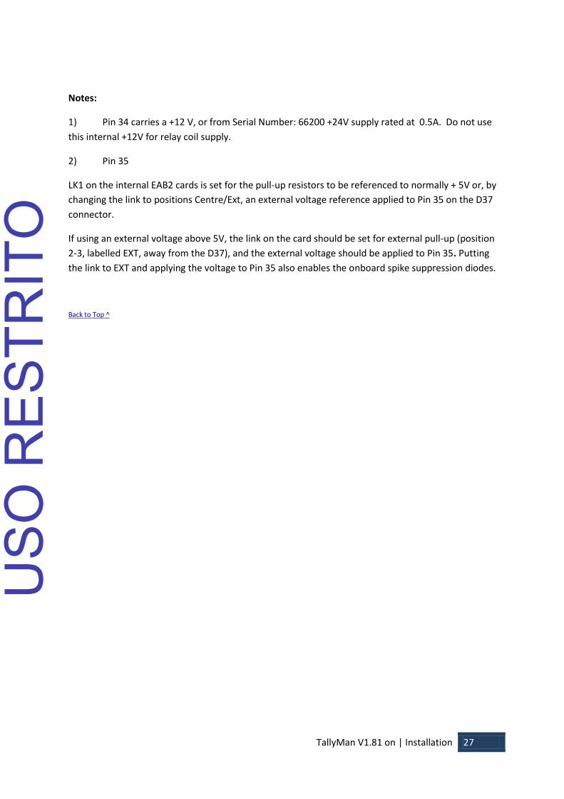
Notes:
1) Pin 34 carries a +12 V, or from Serial Number: 66200 +24V supply rated at 0.5A. Do not use
this internal +12V for relay coil supply.
2) Pin 35
LK1 on the internal EAB2 cards is set for the pull-up resistors to be referenced to normally + 5V or, by
changing the link to positions Centre/Ext, an external voltage reference applied to Pin 35 on the D37
connector.
If using an external voltage above 5V, the link on the card should be set for external pull-up (position
2-3, labelled EXT, away from the D37), and the external voltage should be applied to Pin 35. Putting
the link to EXT and applying the voltage to Pin 35 also enables the onboard spike suppression diodes.
Back to Top ^
USO
RES
TRIT
O

TallyMan V1.81 on | Installation 28
Default IP
The default IP parameters of TSL Tallyman controllers are:
IP Address: 10.0.0.220
Subnet Mask: 255.0.0.0
Connection for configuration purposes is via a PC running TallyMan, available for download from the
TSL website www.TSL.co.uk
Initial setup
Connect a PC running a terminal program (Hyper terminal/Putty/Tera Term Pro for example) to the
Maintenance Port, Port 3 on the TallyMan controller.
HyperTerminal Settings
USO
RES
TRIT
O

TallyMan V1.81 on | Installation 29
Start HyperTerminal and then power up the TM2+ and wait for about 10 secs. Press Y on the
keyboard within 1 sec of the message appearing. Follow the on-screen instruction
Pressing S or Enter on the PC’s keyboard will set the TallyMan units as the Main Unit
Pressing C will set it as a Controller so that it may be an Object in the system tree under a Main Controller, this is not necessary to share objects and tally information between controllers, more information on object sharing can be found in the sharing objects section of the TallyMan configuration manual.
Pressing B will set the unit as a Redundant Backup unit. See the section on Backup for information on how to use this facility.
Pressing D will delete the current setup file; pressing any other key will allow access to the IP settings.
Pressing Y will revert the unit to factory software and will downgrade the unit to the previous version of the TallyMan Program provided that an upgrade has taken place in the field.
IP Addresses are set as shown. If no entry is made and Enter in the PC’s keyboard is pressed the original settings will be kept.
When all settings are correct remove the RS232 cable and re-power the unit.
Notes.
Use the following cable to connect your PC comm. Port to Port 3 of the TallyMan:
USO
RES
TRIT
O

TallyMan V1.81 on | Installation 30
PC TM2+ 2 3
3 2
5 5
Back to Top ^
USO
RES
TRIT
O

TallyMan V1.81 on | Installation 31
TMC-1
The TallyMan controller should be installed in a standard 19” rack with good ventilation, no other
special precautions need be taken, further information regarding earthing, mounting, power etc may
be found in the Safety section.
Connections
Control 1 RS422 – User Assignable. Used for Mixer/Router/Multiviewer connection
Control 2 RS422 – User Assignable. Used for Mixer/Router/Multiviewer connection
Controls 3 -18 RS422 – Optional expansion cards. User Assignable. Used for
Mixer/Router/Multiviewer connection
Ethernet This is for configuration via the configuration PC and network comms with IP capable
devices.
Power The unit is powered via an IEC 60320 C14 coupler. The inlet is auto ranging 100-
240V. No cable is supplied with this device.
USO
RES
TRIT
O

TallyMan V1.81 on | Installation 32
Pin out details
Ethernet
The cable required to connect the TMC-1 controller with the configuring computer is as follows:
Signal Name RJ-45 Ethernet Pin
Numbers
Crossover Cable
Pinouts
TX + 1 3 TX - 2 6 RX + 3 1
EPWR + Power 4 4 EPWR + Power 5 5
RX - 6 2 EPWR - Power 7 7 EPWR - Power 8 8
For a hub connection, use a straight-through cable. For TallyMan Controller to Computer, use a
crossover cable
Back to Top ^
USO
RES
TRIT
O
TallyMan V1.81 on | Installation 33
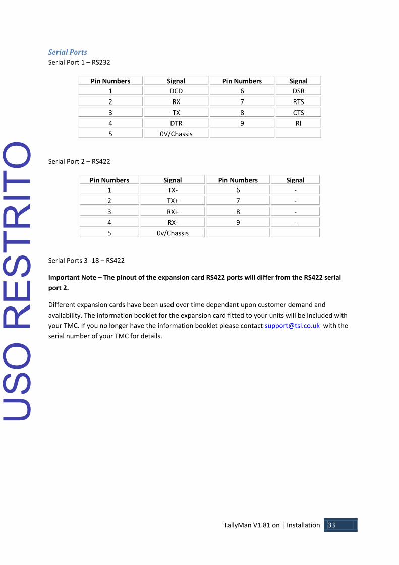
Serial Ports
Serial Port 1 – RS232
Pin Numbers Signal Pin Numbers Signal
1 DCD 6 DSR
2 RX 7 RTS
3 TX 8 CTS
4 DTR 9 RI
5 0V/Chassis
Serial Port 2 – RS422
Pin Numbers Signal Pin Numbers Signal
1 TX- 6 -
2 TX+ 7 -
3 RX+ 8 -
4 RX- 9 -
5 0v/Chassis
Serial Ports 3 -18 – RS422
Important Note – The pinout of the expansion card RS422 ports will differ from the RS422 serial
port 2.
Different expansion cards have been used over time dependant upon customer demand and
availability. The information booklet for the expansion card fitted to your units will be included with
your TMC. If you no longer have the information booklet please contact [email protected] with the
serial number of your TMC for details.
USO
RES
TRIT
O
TallyMan V1.81 on | Installation 34
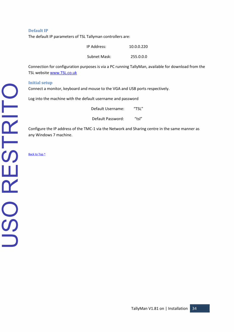
Default IP
The default IP parameters of TSL Tallyman controllers are:
IP Address: 10.0.0.220
Subnet Mask: 255.0.0.0
Connection for configuration purposes is via a PC running TallyMan, available for download from the
TSL website www.TSL.co.uk
Initial setup
Connect a monitor, keyboard and mouse to the VGA and USB ports respectively.
Log into the machine with the default username and password
Default Username: “TSL”
Default Password: “tsl”
Configure the IP address of the TMC-1 via the Network and Sharing centre in the same manner as
any Windows 7 machine.
Back to Top ^
USO
RES
TRIT
O
TallyMan V1.81 on | Specification 35
Specification
TM1
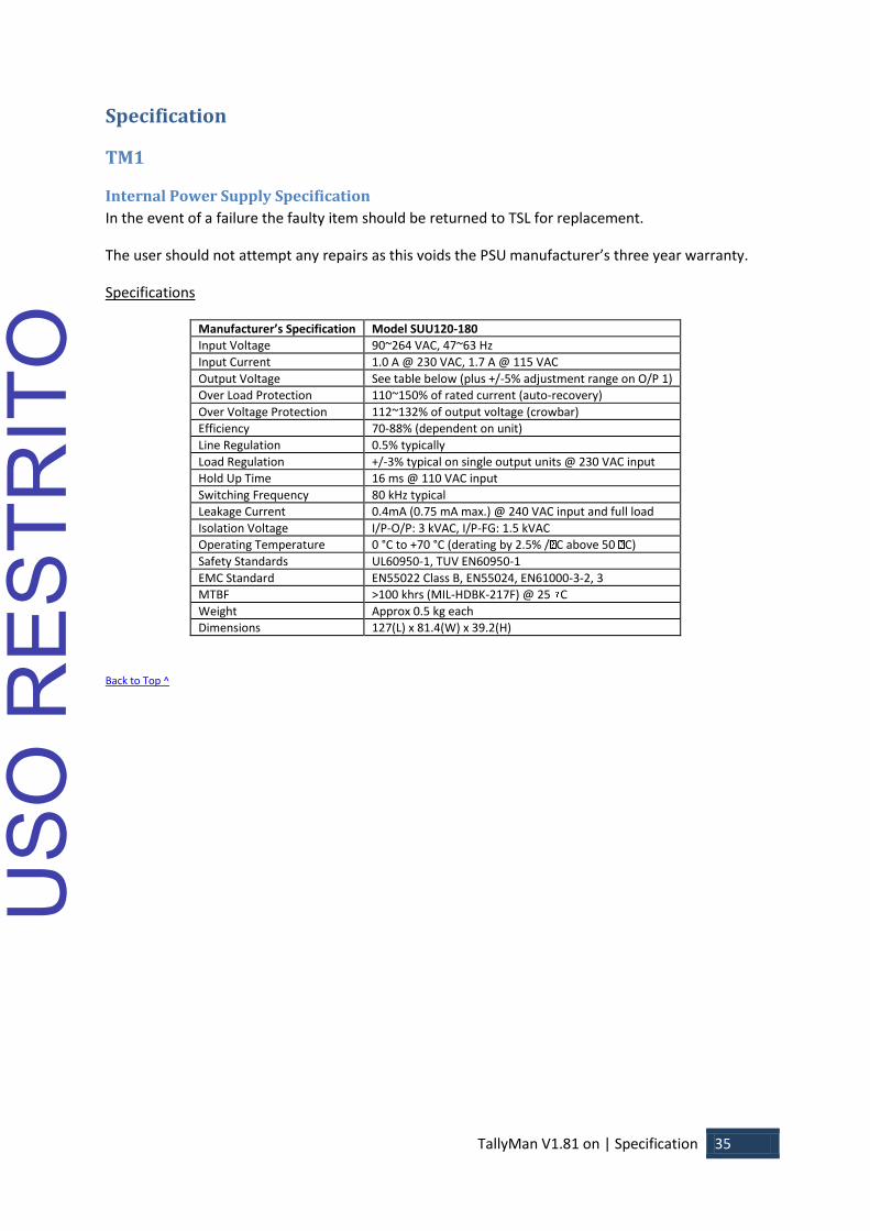
Internal Power Supply Specification
In the event of a failure the faulty item should be returned to TSL for replacement.
The user should not attempt any repairs as this voids the PSU manufacturer’s three year warranty.
Specifications
Manufacturer’s Specification Model SUU120-180
Input Voltage 90~264 VAC, 47~63 Hz
Input Current 1.0 A @ 230 VAC, 1.7 A @ 115 VAC
Output Voltage See table below (plus +/-5% adjustment range on O/P 1)
Over Load Protection 110~150% of rated current (auto-recovery)
Over Voltage Protection 112~132% of output voltage (crowbar)
Efficiency 70-88% (dependent on unit)
Line Regulation 0.5% typically
Load Regulation +/-3% typical on single output units @ 230 VAC input
Hold Up Time 16 ms @ 110 VAC input
Switching Frequency 80 kHz typical
Leakage Current 0.4mA (0.75 mA max.) @ 240 VAC input and full load
Isolation Voltage I/P-O/P: 3 kVAC, I/P-FG: 1.5 kVAC
Operating Temperature 0 °C to +70 °C (derating by 2.5% / C above 50 C)
Safety Standards UL60950-1, TUV EN60950-1
EMC Standard EN55022 Class B, EN55024, EN61000-3-2, 3
EN61000-4-2, 3, 4, 5, 6, 8, 11
MTBF >100 khrs (MIL-HDBK-217F) @ 25 C
Weight Approx 0.5 kg each
Dimensions 127(L) x 81.4(W) x 39.2(H)
Back to Top ^
USO
RES
TRIT
O
TallyMan V1.81 on | Specification 36
TM2
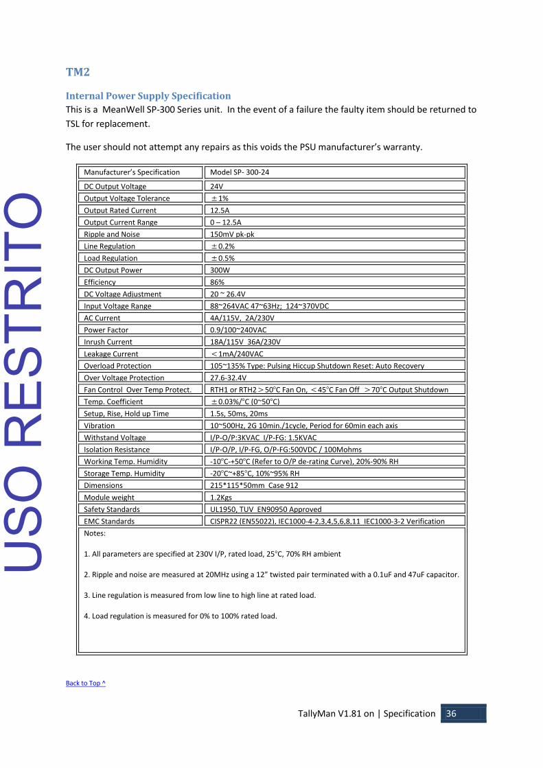
Internal Power Supply Specification
This is a MeanWell SP-300 Series unit. In the event of a failure the faulty item should be returned to
TSL for replacement.
The user should not attempt any repairs as this voids the PSU manufacturer’s warranty.
Manufacturer’s Specification Model SP- 300-24
DC Output Voltage 24V
Output Voltage Tolerance 1%
Output Rated Current 12.5A
Output Current Range 0 – 12.5A
Ripple and Noise 150mV pk-pk
Line Regulation 0.2%
Load Regulation 0.5%
DC Output Power 300W
Efficiency 86%
DC Voltage Adjustment 20 ~ 26.4V
Input Voltage Range 88~264VAC 47~63Hz; 124~370VDC
AC Current 4A/115V, 2A/230V
Power Factor 0.9/100~240VAC
Inrush Current 18A/115V 36A/230V
Leakage Current 1mA/240VAC
Overload Protection 105~135% Type: Pulsing Hiccup Shutdown Reset: Auto Recovery
Over Voltage Protection 27.6-32.4V
Fan Control Over Temp Protect. RTH1 or RTH250C Fan On, 45C Fan Off 70C Output Shutdown
Temp. Coefficient 0.03%/C (0~50C)
Setup, Rise, Hold up Time 1.5s, 50ms, 20ms
Vibration 10~500Hz, 2G 10min./1cycle, Period for 60min each axis
Withstand Voltage I/P-O/P:3KVAC I/P-FG: 1.5KVAC
O/P-FG:0.5KVAC Isolation Resistance I/P-O/P, I/P-FG, O/P-FG:500VDC / 100Mohms
Working Temp. Humidity -10C-+50C (Refer to O/P de-rating Curve), 20%-90% RH
Storage Temp. Humidity -20C~+85C, 10%~95% RH
Dimensions 215*115*50mm Case 912
Module weight 1.2Kgs
Safety Standards UL1950, TUV EN90950 Approved
EMC Standards CISPR22 (EN55022), IEC1000-4-2,3,4,5,6,8,11 IEC1000-3-2 Verification
Notes:
1. All parameters are specified at 230V I/P, rated load, 25C, 70% RH ambient
2. Ripple and noise are measured at 20MHz using a 12” twisted pair terminated with a 0.1uF and 47uF capacitor.
3. Line regulation is measured from low line to high line at rated load.
4. Load regulation is measured for 0% to 100% rated load.
Back to Top ^
USO
RES
TRIT
O

TallyMan V1.81 on | Specification 37
USO
RES
TRIT
O

TallyMan V1.81 on | Specification 38
TM2+
Internal Power Supply Specification
This is a MeanWell SP-300 Series unit. In the event of a failure the faulty item should be returned to
TSL for replacement.
The user should not attempt any repairs as this voids the PSU manufacturer’s warranty.
Manufacturer’s Specification Model SP- 300-24
DC Output Voltage 24V
Output Voltage Tolerance 1%
Output Rated Current 12.5A
Output Current Range 0 – 12.5A
Ripple and Noise 150mV pk-pk
Line Regulation 0.2%
Load Regulation 0.5%
DC Output Power 300W
Efficiency 86%
DC Voltage Adjustment 20 ~ 26.4V
Input Voltage Range 88~264VAC 47~63Hz; 124~370VDC
AC Current 4A/115V, 2A/230V
Power Factor 0.9/100~240VAC
Inrush Current 18A/115V 36A/230V
Leakage Current 1mA/240VAC
Overload Protection 105~135% Type: Pulsing Hiccup Shutdown Reset: Auto Recovery
Over Voltage Protection 27.6-32.4V
Fan Control Over Temp Protect. RTH1 or RTH250C Fan On, 45C Fan Off 70C Output Shutdown
Temp. Coefficient 0.03%/C (0~50C)
Setup, Rise, Hold up Time 1.5s, 50ms, 20ms
Vibration 10~500Hz, 2G 10min./1cycle, Period for 60min each axis
Withstand Voltage I/P-O/P:3KVAC I/P-FG: 1.5KVAC
O/P-FG:0.5KVAC Isolation Resistance I/P-O/P, I/P-FG, O/P-FG:500VDC / 100Mohms
Working Temp. Humidity -10C-+50C (Refer to O/P de-rating Curve), 20%-90% RH
Storage Temp. Humidity -20C~+85C, 10%~95% RH
Dimensions 215*115*50mm Case 912
Module weight 1.2Kgs
Safety Standards UL1950, TUV EN90950 Approved
EMC Standards CISPR22 (EN55022), IEC1000-4-2,3,4,5,6,8,11 IEC1000-3-2 Verification
Notes:
1. All parameters are specified at 230V I/P, rated load, 25C, 70% RH ambient
2. Ripple and noise are measured at 20MHz using a 12” twisted pair terminated with a 0.1uF and 47uF capacitor.
3. Line regulation is measured from low line to high line at rated load.
4. Load regulation is measured for 0% to 100% rated load.
Back to Top ^
USO
RES
TRIT
O
TallyMan V1.81 on | Specification 39
TMC-1
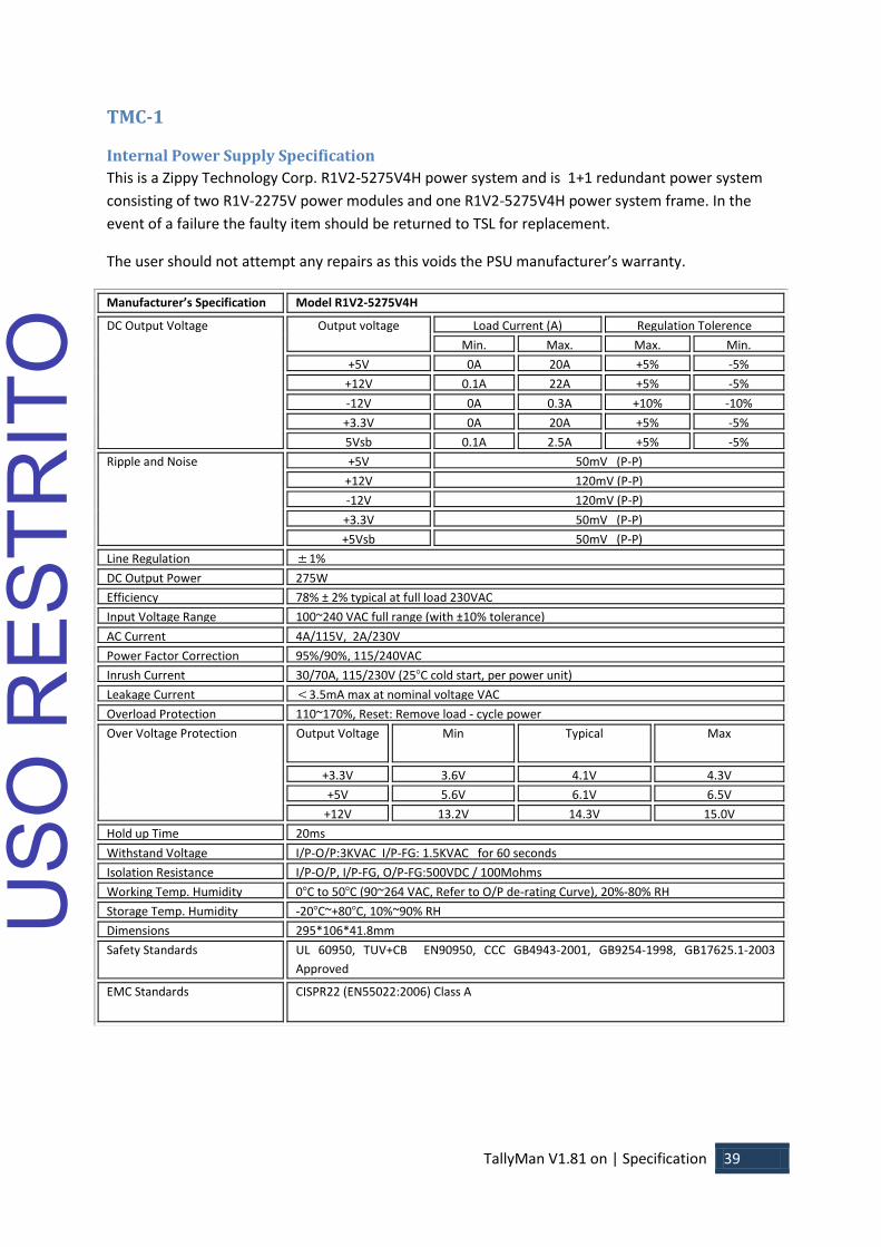
Internal Power Supply Specification
This is a Zippy Technology Corp. R1V2-5275V4H power system and is 1+1 redundant power system
consisting of two R1V-2275V power modules and one R1V2-5275V4H power system frame. In the
event of a failure the faulty item should be returned to TSL for replacement.
The user should not attempt any repairs as this voids the PSU manufacturer’s warranty.
Manufacturer’s Specification Model R1V2-5275V4H
DC Output Voltage Output voltage Load Current (A) Regulation Tolerence
Min. Max. Max. Min.
+5V 0A 20A +5% -5%
+12V 0.1A 22A +5% -5%
-12V 0A 0.3A +10% -10%
+3.3V 0A 20A +5% -5%
5Vsb 0.1A 2.5A +5% -5%
Ripple and Noise +5V 50mV (P-P)
+12V 120mV (P-P)
-12V 120mV (P-P)
+3.3V 50mV (P-P)
+5Vsb 50mV (P-P)
9 Line Regulation 1%
DC Output Power 275W
Efficiency 78% ± 2% typical at full load 230VAC
Input Voltage Range 100~240 VAC full range (with ±10% tolerance)
AC Current 4A/115V, 2A/230V
Power Factor Correction 95%/90%, 115/240VAC
Inrush Current 30/70A, 115/230V (25C cold start, per power unit)
Leakage Current 3.5mA max at nominal voltage VAC
Overload Protection 110~170%, Reset: Remove load - cycle power
Over Voltage Protection Output Voltage Min Typical Max
+3.3V 3.6V 4.1V 4.3V
+5V 5.6V 6.1V 6.5V
+12V 13.2V 14.3V 15.0V
Hold up Time 20ms
Withstand Voltage I/P-O/P:3KVAC I/P-FG: 1.5KVAC for 60 seconds
Isolation Resistance I/P-O/P, I/P-FG, O/P-FG:500VDC / 100Mohms
Working Temp. Humidity 0C to 50C (90~264 VAC, Refer to O/P de-rating Curve), 20%-80% RH
Storage Temp. Humidity -20C~+80C, 10%~90% RH
Dimensions 295*106*41.8mm
Safety Standards UL 60950, TUV+CB EN90950, CCC GB4943-2001, GB9254-1998, GB17625.1-2003
Approved
EMC Standards CISPR22 (EN55022:2006) Class A
USO
RES
TRIT
O

TallyMan V1.81 on | Specification 40
Motherboard
Supplier – Impulse Corp UK
Part number – SBC81205VGG
CPU
Part number - Intel Core 2 Duo E7400 - 2.8Ghz 3Mb Cache 1066 FSB, Dual Core Processor, 775
Socket
Memory
Specification - 2GB, DDR2 SDRAM , 240 pin DIMM, 1.8V
Supplier – Dabs
Disk Drive (Solid state)
Specification – SATA 2 SSD, 30GB
Part number for supplier – OCZSSD2-1VTX30G
Supplier – OCZ Technology
Back to Top ^
USO
RES
TRIT
O

TallyMan V1.81 on | Safety 41
Safety
Installation Unless otherwise stated TSL equipment may be installed at any angle or position within an operating temperature range of 5 ~ 25 degrees C. The RJ45 connectors are for use only with TSL UMD equipment. All TSL equipment conforms to the EC Low Voltage Directive: EC Low Voltage Directive (73/23/EEC) (OJ L76 26.3.73) (LVD). Amendment: (93/68/EEC) (OJ L220 30.8.93).
Earthing/Grounding
In all cases, the frame of the equipment should be earthed on installation. Connection to an earthed
strip running the length of the frame is ideal.
The earth pin on the IEC mains inlet connector is connected to the metal frame of the equipment, to
0 volts on the internal DC PSU and to signal ground, unless otherwise stated. All metal panels are
bonded together. Rack mounted equipment must be earthed (grounded).
Mounting
Careful consideration of the equipment location and mounting in racks must be made. In particular,
consideration must be given to the stability of free-standing racks by mounting heavy equipment low
in the rack. The rear of the unit should be supported in the rack.
Power
For pluggable equipment, the socket outlet shall be installed near the equipment and shall be easily
accessible.
Consideration must be given to the supply circuit loading and switch on/fault surges that will affect
over current protection trips and switches etc.
Check that the fuse rating is correct for the local power (mains) supply. Replacement fuses must be
of the same rating and type for continued protection against fire risk.
The equipment rating is shown on the rear panel.
No power supply cord is provided with this equipment.
Do not switch on until all connections are made.
Ventilation
Due consideration for cooling requirements must be given when mounting the equipment.
If the equipment is installed in a closed unit, consideration must be given to providing forced air
cooling in order that the maximum recommended temperature is not exceeded. Introduction 9
TallyMan V 1.7.1b on
Back to Top ^
USO
RES
TRIT
O
TallyMan V1.81 on | Safety 42
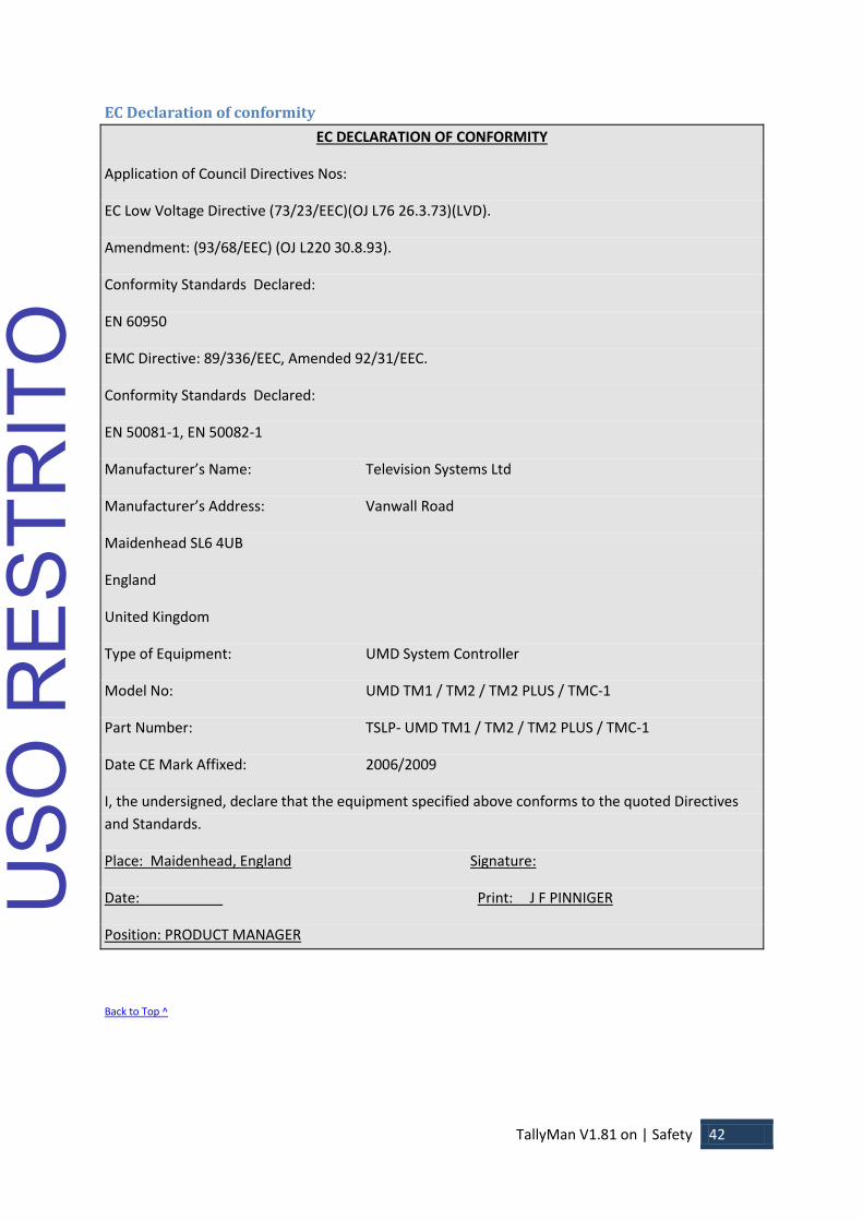
EC Declaration of conformity
EC DECLARATION OF CONFORMITY
Application of Council Directives Nos:
EC Low Voltage Directive (73/23/EEC)(OJ L76 26.3.73)(LVD).
Amendment: (93/68/EEC) (OJ L220 30.8.93).
Conformity Standards Declared:
EN 60950
EMC Directive: 89/336/EEC, Amended 92/31/EEC.
Conformity Standards Declared:
EN 50081-1, EN 50082-1
Manufacturer’s Name: Television Systems Ltd
Manufacturer’s Address: Vanwall Road
Maidenhead SL6 4UB
England
United Kingdom
Type of Equipment: UMD System Controller
Model No: UMD TM1 / TM2 / TM2 PLUS / TMC-1
Part Number: TSLP- UMD TM1 / TM2 / TM2 PLUS / TMC-1
Date CE Mark Affixed: 2006/2009
I, the undersigned, declare that the equipment specified above conforms to the quoted Directives
and Standards.
Place: Maidenhead, England Signature:
Date: Print: J F PINNIGER
Position: PRODUCT MANAGER
Back to Top ^
USO
RES
TRIT
O

TallyMan V1.81 on | Warranty, Maintenance and Repair 43
Warranty, Maintenance and Repair All TSL equipment is guaranteed for one year from the date of delivery to the customer’s premises. If
the equipment is to be stored for a significant period, please contact TSL concerning a possible
extended warranty period.
Failure during warranty If any TSL product should fail or become faulty within the warranty period, first please check the PSU
fuses.
All maintenance work must be carried out by trained and competent personnel.
Technical support information E-Mail address: [email protected]
Telephone Support Number: +44 (0) 1628 676221
If equipment has to be returned to TSL for repair or re-alignment, please observe the following:
TSL Returns Procedure Please email [email protected] or telephone +44 (0)1628 676221 and ask for Technical Support
who will assist in diagnosing the fault and will provide a Returns Number (RMA). This will enable us
to track the unit effectively and will provide some information prior to the unit arriving.
For each item, this unique Returns Number must be included with the Fault Report sent with the
unit.
A contact name and telephone number are also required with the Fault Report sent with the unit.
Fault report details required
Company:
Name:
Address:
Contact Name:
Telephone No:
Returns Number:
Symptoms of the fault (to include switch setting positions, input signals etc):
Packing
Please ensure that the unit is well packed as all mechanical damage is chargeable. TSL recommends
that you insure your equipment for transit damage.
The original packaging, when available, should always be used when returning equipment.
If returned equipment is received in a damaged condition, the damage should be reported both to
TSL and the carrier immediately.
Back to Top ^
USO
RES
TRIT
O


![Modul Aplikasi Komputer [TM2]](https://static.fdocuments.net/doc/165x107/55cf8557550346484b8cfbe9/modul-aplikasi-komputer-tm2.jpg)


![Product Overview - Cloudinaryg_center/assets/… · Product Overview 2/4-CH Modular Type, PID Control Temperature Controller [TM Series] Series TM2 TM4 Appearances & Dimensions No.](https://static.fdocuments.net/doc/165x107/600fc35735b4fa73f35e7bd0/product-overview-cloudinary-gcenterassets-product-overview-24-ch-modular.jpg)


![Modul Audit Energi [TM2]](https://static.fdocuments.net/doc/165x107/563dbb55550346aa9aac3c3b/modul-audit-energi-tm2.jpg)