TADANO ROUGH TERRAIN CRANE MODEL GR-550EXarnab.se/wp-content/uploads/2012/09/GR-550EX_EN.pdf · - 2...
SPEC. SHEET No. GR-550E-1-00214/EU-51 DATE June, 2010 (Left-hand steering) GENERAL DATA CRANE CAPACITY m 0 . 3 t a g k 0 0 0 , 5 5 BOOM 11.1 m - 42.0m , n o i t c e s - 5 DIMENSION m m 5 9 6 , 3 1 . x o r p p a h t g n e l l l a r e v O m m 5 1 3 , 3 . x o r p p a h t d i w l l a r e v O m m 0 6 8 , 3 . x o r p p a t h g i e h l l a r e v O MASS Gross vehicle mass approx. 43,690 kg -front axle approx. 23,975 kg -rear axle approx. 19,715 kg PERFORMANCE Max. traveling speed computed 20 km/h Gradeability (tan θ ) computed 153 % (at stall) *30 % * Machine should be operated within the limit of engine crankcase design (17 o : MITSUBISHI 6M60-TLU3B). Specifications are subject to change without notice. TADANO ROUGH TERRAIN CRANE MODEL : GR-550EX
Transcript of TADANO ROUGH TERRAIN CRANE MODEL GR-550EXarnab.se/wp-content/uploads/2012/09/GR-550EX_EN.pdf · - 2...

SPEC. SHEET No. GR-550E-1-00214/EU-51DATE June, 2010
(Left-hand steering)
G E N E R A L D ATA
CRANE CAPACITY m0.3tagk000,55
BOOM 11.1 m- 42.0m,noitces-5
DIMENSION
mm596,31.xorppahtgnelllarevOmm513,3.xorppahtdiwllarevOmm068,3.xorppathgiehllarevO
MASS
Gross vehicle mass approx. 43,690 kg-front axle approx. 23,975 kg-rear axle approx. 19,715 kg
PERFORMANCE
Max. traveling speed computed 20 km/hGradeability (tan θ ) computed 153 % (at stall)
*30 %
* Machine should be operated within the limit of engine crankcasedesign (17o : MITSUBISHI 6M60-TLU3B).
Specifications are subject to change without notice.
TADANO ROUGH TERRAIN CRANE
MODEL : GR-550EX

- 2 -
SPEC. SHEET No. GR-550E-1-00214/EU-51
C R A N E S P E C I F I C AT I O N S
MODEL GR-550EX
CAPACITY 55,000 kg at 3.0 m
BOOM 5-section full power partially synchronized telescoping boom of roundhexagonal box construction with 5 sheaves at boom head. Thesynchronization system consists of 2 telescope cylinders, extensioncables and retraction cables.Hydraulic cylinders fitted with holding valves.
Fully retracted length………….11.1 mFully extended length………… 42.0 mExtension speed……………….30.9 m in 128 s
JIB 5.3(tesffoelpirT.noisnetxemoobdnuoragniwsdegats-2 o/25o/45o) type.Stores alongside base boom section.Assistant cylinders for mounting and stowing.Single sheave at jib head.
Length…………………………..9.9 m and 17.7 m
SINGLE TOP (AUXILIARY Single sheave.BOOM SHEAVE) Mounted to main boom head for single line work.
ELEVATION By a double-acting hydraulic cylinder, fitted with holding valve.Boom angle………………….....-1.4o to 80.5o
Boom raising speed…………...20o to 60o in 39 s
HOIST - Main winch Variable speed type with grooved drum driven by hydraulic axial pistonmotor through winch speed reducer. Power load lowering and hoisting.Equipped with automatic brake (Neutral brake) and counterbalancevalve. Controlled independently of auxiliary winch.
Single line pull………………….54.9 kN {5,600 kgf}Single line speed………………147 m/min (at the 4th layer)Wire rope………………………. No-spin type
Diameter x length…………19 mm x 231 m

- 3 -
SPEC. SHEET No. GR-550E-1-00214/EU-51
HOIST - Variable speed type with grooved drum driven by hydraulic axial pistonAuxiliary winch motor through winch speed reducer. Power load lowering and hoisting.
Equipped with automatic brake (Neutral brake) and counterbalancevalve. Controlled independently of main winch.
Single line pull………………….54.9 kN {5,600 kgf}Single line speed………………126 m/min (at the 2nd layer)Wire rope……………………….No-spin type
Diameter x length…………19 mm x 129 m
SWING Hydraulic axial piston motor driven through planetary speed reducer.Continuous 360o full circle swing on ball bearing slew ring.Equipped with manually locked/released swing brake.
Swing speed……………………2.5 min-1 {rpm}
HYDRAULIC SYSTEM Pumps…………….. 2 variable piston pumps for telescoping, elevatingand winches.Tandem gear pump for steering, swing and optionalequipment.
Control valves……..Multiple valves actuated by pilot pressure withintegral pressure relief valves.
Circuit………………Equipped with air cooled type oil cooler.Oil pressure appears on AML display for maincircuit.
Hydraulic oil tank capacity…..approx. 740 liters
Filters……………… Return line filter
CRANE CONTROL By 4 control levers for swing, boom hoist, main winch, boom telescopingor auxiliary winch with 2 control pedals for boom hoist and boomtelescoping based on ISO standard layout. Control lever stands canchange neutral positions and tilt for easy access to cab.

- 4 -
SPEC. SHEET No. GR-550E-1-00214/EU-51
CAB bacenomorfdemrofrepebnacsnoitarepoevirddnaenarchtoBmounted on rotating superstructure. One sided one-man type, steelconstruction with sliding door access and tinted safety glass windowsopening at side. Door window is powered control.Operator's 3 way adjustable seat with headrest and armrest.
TADANO Automatic Main unit in crane cab gives audible and visual warning of approach toMoment Limiter overload. Automatically cuts out crane motions before overload. With(Model: AML-C) working range (load radius and/or boom angle and/or tip height and/or
swing range) limit function.Automatic Speed Reduction and Soft Stop function on boom elevatingand swing.Following functions are displayed.
Load as percentageNumber of parts of line of ropeBoom angleBoom lengthLoad radiusOutriggers positionOn-tire indicatorActual hook loadPermissible loadBoom position indicatorPotential hook heightSwing angleMain hydraulic oil pressureJib length and jib offset angle (only when jib operation)
OUTRIGGERS Hydraulically operated H-type outriggers. Each outrigger controlledsimultaneously or independently from the cab.Equipped with sight level gauge. Floats mounted integrally with thejacks retract to within vehicle width.All cylinders fitted with pilot check valves.Crane operation with different extended length of each outrigger.Equipped with extension width detector for each outrigger.
Extended widthFully……………...7,200 mmMiddle…………... 6,700 mmMiddle…………... 5,500 mmMinimum………...2,800 mm
Float size (Diameter)………… 500 mm
COUNTERWEIGHT Integral with swing frameMass……………..5,100 kg
---------------------------------------------------------------------------------------------------------------------------------------NOTE : Each crane motion speed is based on unladen conditions.

- 5 -
SPEC. SHEET No. GR-550E-1-00214/EU-51
C A R R I E R S P E C I F I C AT I O N S
TYPE yb(epytdetcelesyaw-2elxagnivird,gnireetsdnahtfel,enigneraeRmanual switch).
4 x 2 front drive4 x 4 front and rear drive
FRAME High-tensile steel, all welded mono-box construction.
ENGINE Model……. MITSUBISHI 6M60-TLU3B [EUROMOT Stage ΙΙΙA]Type………4 cycle, turbo charged and after cooled, 6 cylinder in line,
direct injection, water cooled diesel engine.Piston displacement…….. 7,545 cm3
Bore x stroke……………...118 mm x 115 mmMax. output………………. 200 kW {272 PS} at 2,600 min-1 {rpm}Max. torque………………. 785 N-m {80 kgf-m} at 1,400 min-1 {rpm}
TRANSMISSION Electronically controlled full automatic transmission.Torque converter driving full powershift with driving axle selector.6 forward and 2 reverse speeds.2 speeds - High range - 2 wheel drive ; 4 wheel drive3 speeds - Low range - 4 wheel drive
AXLES Front……...Full floating type, steering and driving axle with planetaryreduction.
Rear………Full floating type, steering and driving axle with planetaryreduction.Non-spin differential.
STEERING Hydraulic power steering controlled by steering wheel.Four steering modes available:
2-wheel front2-wheel rear4-wheel coordinated4-wheel crab
SUSPENSION Front……...Rigid mounted to the frame.Rear………Pivot mounted with hydraulic lockout cylinders.
BRAKE SYSTEM Service…...Air over hydraulic disc brakes on all 4 wheels.Parking / Emergency…..
Spring applied-air released brake acting on input shaft offront axle.
Auxiliary….Electro-pneumatic operated exhaust brake.
ELECTRIC SYSTEM 24 V DC. 2 batteries of 12 V - 120 Ah capacity.
FUEL TANK CAPACITY 300 liters
TIRES Front……...29.5-25 22PR(OR) or 29.5-25 28PR(OR), Single x 2………raeR 29.5-25 22PR(OR) or 29.5-25 28PR(OR), Single x 2
TURN RADIUS Min. turning radius (at center of extreme outer tire)2-wheel steering…………...11.9 m4-wheel steering…………… 6.7 m

- 6 -
SPEC. SHEET No. GR-550E-1-00214/EU-51
E Q U I P M E N TSTANDARD EQUIPMENT Automatic moment limiter (AML)
External lamp and buzzer (AML)Pendant type over-winding cutoutWinch automatic fail-safe brakeOver-unwinding preventionCable follower
40 t capacity hook block (4-sheaves)5.6 t capacity hook block (swivel hook)Hook safety latchPilot check valvesHolding valvesCounterbalance valvesHydraulic pressure relief valvesSwing brakeSwing lock (360o positive swing lock)Boom angle indicatorBoom elevation foot pedalBoom telescoping foot pedalOutrigger extension width detectorEmergency engine stop systemAir conditioner (hot water heater and cooler)Outrigger control box (Both sides of carrier)Sight level gaugeHydraulic oil coolerElectric windshield wiper and washerRoof window wiper and washerPower window (Cab door)Tachometer/Speedometer3 way adjustable cloth seat with seat belt, headrest and armrestCab floor matSun visor (Front and roof)Automatic drive systemEmergency steeringTransmission neutral position engine startOvershift preventionParking braked travel warningTilt-telescope steering wheelBack-up alarmAir cleaner dust indicatorAir dryerWater separator with filterEngine over-run alarmHydraulic lockout suspensionNon-spin differential (Rear)Towing eyes - front and rear
Winch drum rotation indicatorWinch drum mirror
OPTIONAL EQUIPMENT 55 t capacity hook block (6 sheaves)20 t capacity hook block (2 sheaves)Electric fanTire inflation kit

- 7 -
SPEC. SHEET No. GR-550E-1-00214/EU-51
RATED LIFTING CAPACITIESEN 13000
ON OUTRIGGERS Unit : x 1000kg
AB C C C C C C C C C C
3.0 67.5 55.0 73.7 40.8 77.4 30.0 76.9 22.03.5 64.4 53.4 71.7 40.8 75.9 30.0 75.4 22.04.0 61.3 48.4 69.6 40.8 74.4 30.0 74.0 22.0 79.8 22.0 79.5 14.04.5 58.3 43.8 67.5 40.8 72.8 30.0 72.3 22.0 78.7 22.0 78.4 14.05.0 55.0 39.8 65.4 38.9 71.3 29.0 70.8 22.0 77.8 22.0 77.5 14.05.5 51.8 36.0 63.2 35.6 69.6 27.2 69.1 22.0 76.7 21.5 76.3 13.66.0 48.3 32.8 60.9 32.4 67.9 25.0 67.5 21.6 75.6 20.0 75.2 12.8 79.3 14.0 78.9 8.06.5 44.5 30.1 58.7 29.7 66.2 23.4 65.8 20.8 74.5 18.9 74.2 12.0 78.5 14.0 78.1 8.07.0 40.5 27.8 56.3 27.4 64.4 22.0 64.1 20.1 73.2 17.8 73.0 11.4 77.7 13.5 77.4 8.0 79.2 8.08.0 31.4 23.6 51.4 23.1 60.9 19.5 60.7 18.8 71.0 15.8 70.8 10.3 76.0 12.5 75.7 8.0 77.9 8.0 79.1 8.09.0 15.8 17.5 46.1 18.7 57.2 17.0 56.9 17.7 68.6 14.3 68.4 9.3 74.2 11.3 74.1 7.6 76.6 8.0 77.9 8.0
10.0 40.0 15.2 53.3 14.5 53.1 16.0 66.3 13.0 66.0 8.5 72.5 10.4 72.3 7.0 75.1 7.5 76.7 8.011.0 33.2 12.4 49.2 12.0 48.9 14.2 63.8 11.8 63.6 7.8 70.7 9.6 70.5 6.4 73.5 6.9 75.2 7.512.0 24.9 10.5 44.8 10.0 44.5 12.3 61.2 10.8 61.0 7.2 68.9 8.8 68.7 5.8 71.9 6.4 73.9 6.913.0 10.3 8.9 39.8 8.5 39.6 10.7 58.7 9.5 58.5 6.7 67.0 8.2 66.9 5.4 70.3 5.9 72.5 6.514.0 34.8 7.2 34.0 9.3 55.8 8.2 55.8 6.2 65.3 7.6 64.9 4.9 68.6 5.5 71.0 6.015.0 28.4 6.1 27.8 8.2 53.2 7.2 53.2 5.8 63.4 7.0 63.0 4.6 67.0 5.1 69.5 5.616.0 20.4 5.2 20.0 7.3 50.2 6.3 50.3 5.5 61.3 6.5 61.0 4.2 65.2 4.7 67.9 5.217.0 47.1 5.5 47.2 5.3 59.4 6.0 59.0 3.9 63.6 4.4 66.5 4.918.0 43.8 4.8 44.1 5.0 57.2 5.3 57.0 3.6 61.8 4.1 64.9 4.619.0 40.4 4.2 40.6 4.8 55.2 4.7 54.9 3.4 60.0 3.8 63.2 4.320.0 36.8 3.7 36.9 4.6 53.0 4.2 52.8 3.2 58.2 3.6 61.7 4.022.0 28.2 2.8 28.3 3.9 48.3 3.3 48.2 2.9 54.3 3.1 58.4 3.424.0 15.9 2.1 15.7 3.3 43.2 2.5 43.3 2.6 50.0 2.8 54.9 2.826.0 37.6 1.9 37.8 2.3 45.6 2.5 51.1 2.228.0 31.3 1.4 31.6 2.1 40.7 2.0 47.2 1.730.0 23.5 1.0 23.7 1.9 35.2 1.6 43.1 1.332.0 11.9 0.7 11.6 1.6 29.0 1.2 38.7 0.934.0 21.6 0.936.0 8.9 0.7D
TelescopingMode
2nd boom3rd boom4th boomTop boom
A :Boom length (m) B :Load radius (m)C :Loaded boom angle (o)D :Minimum boom angle (o) for indicated length (no load)
100100
0 0 0 33 33 66 66 100 100
1000 0 0 33 33 66 66 100 100
1000 0 0 33 33 66 66 100 100
Telescoping conditions (%)
0 50 100 0 100 0 100 0 50
42.0
37o0o
Ι,ΙΙ Ι Ι ΙΙ Ι ΙΙ
Outriggers fully extended (7.2m)360o Rotation
11.1 15.0 18.8 26.6 34.3 38.1
Ι ΙΙ ΙΙ Ι,ΙΙ

- 8 -
SPEC. SHEET No. GR-550E-1-00214/EU-51
RATED LIFTING CAPACITIESEN 13000
ON OUTRIGGERS Unit: x 1000kg
R W R W R W R W R W R W80o 9.6 4.0 13.0 3.5 14.9 3.0 12.0 2.7 18.1 2.0 22.4 1.475o 14.9 4.0 17.7 3.0 19.1 2.5 18.1 2.6 23.3 1.6 27.1 1.370o 19.3 3.1 22.1 2.4 23.2 2.1 23.2 1.9 27.9 1.3 31.2 1.165o 23.5 2.4 26.2 2.0 27.2 1.8 28.2 1.5 32.1 1.0 34.8 0.960o 27.4 2.0 29.9 1.6 30.9 1.5 32.6 1.2 36.3 0.9 38.4 0.855o 30.9 1.6 33.3 1.4 34.0 1.3 36.5 0.9 40.0 0.7 41.8 0.750o 34.0 1.0 36.2 0.9 36.7 0.9 39.9 0.545o 37.1 0.6 38.9 0.5 39.2 0.5
R W R W R W R W R W R W80o 7.6 5.6 11.4 4.7 13.7 3.4 10.1 3.6 16.3 2.4 20.3 1.675o 11.9 5.6 15.1 4.0 17.3 3.1 15.2 3.6 20.7 2.1 24.3 1.570o 15.7 4.8 18.7 3.4 20.5 2.8 19.7 3.0 24.7 1.8 27.8 1.465o 19.2 3.8 21.9 2.9 23.5 2.5 23.8 2.4 28.5 1.6 31.1 1.360o 22.5 3.2 25.1 2.5 26.3 2.3 27.7 2.0 32.0 1.4 34.1 1.255o 25.6 2.7 27.9 2.2 28.9 2.1 31.3 1.6 35.2 1.3 36.7 1.150o 28.4 2.0 30.5 1.8 31.3 1.7 34.5 1.2 38.0 1.0 39.1 1.045o 31.0 1.4 32.9 1.3 33.3 1.2 37.5 0.8 40.5 0.7 41.1 0.640o 33.4 1.0 35.0 0.9 40.3 0.535o 35.7 0.7 36.9 0.6
R W R W R W R W R W R W80o 8.9 4.5 12.7 4.1 14.8 3.1 10.9 2.8 17.7 2.2 21.7 1.575o 13.8 4.5 16.7 3.2 18.6 2.6 16.6 2.8 22.3 1.8 25.9 1.370o 17.7 3.4 20.6 2.6 22.2 2.2 21.3 2.1 26.5 1.4 29.7 1.165o 21.5 2.6 24.2 2.1 25.6 1.8 25.8 1.6 30.5 1.1 33.3 1.060o 25.1 2.1 27.6 1.7 28.8 1.6 30.0 1.3 34.3 0.9 36.4 0.855o 28.4 1.7 30.8 1.5 31.7 1.4 33.9 1.0 37.8 0.8 39.3 0.750o 31.5 1.4 33.6 1.3 34.2 1.2 37.6 0.8 41.0 0.7 42.0 0.645o 34.4 1.2 36.2 1.1 36.5 1.0 41.1 0.6 43.9 0.6 44.5 0.540o 36.9 0.8 38.5 0.835o 39.3 0.5 40.6 0.5
C : Boom angle (o)R : Load radius (m)W : Rated lifting capacity
45o offset 3.5o offset
3.5o offset 25o offset
Outriggers fully extended (7.2m)360o Rotation
34.3m Boom ( telescoping mode Ι )+ 17.7m Jib
C
34.3m Boom ( telescoping mode Ι )+ 9.9m Jib
25o offset 45o offset
38.1m Boom ( telescoping mode ΙΙ )+ 17.7m Jib
45o offset
Outriggers fully extended (7.2m)360o Rotation
C42.0m Boom + 9.9m Jib 42.0m Boom + 17.7m Jib
3.5o offset 25o 52tesffo o offset 45o offset
3.5o offset
25o offset 45o offset
Outriggers fully extended (7.2m)360o Rotation
C3.5o offset
38.1m Boom ( telescoping mode ΙΙ )+ 9.9m Jib
3.5o offset25o offset
45o offset

- 9 -
SPEC. SHEET No. GR-550E-1-00214/EU-51
RATED LIFTING CAPACITIESEN 13000
ON OUTRIGGERS Unit: x 1000kg
C C C C C C C C C C
3.0 67.5 55.0 73.7 40.8 77.4 30.0 76.9 22.03.5 64.4 53.4 71.7 40.8 75.9 30.0 75.4 22.04.0 61.3 48.4 69.6 40.8 74.4 30.0 74.0 22.0 79.8 22.0 79.5 14.04.5 58.3 43.8 67.5 40.8 72.8 30.0 72.3 22.0 78.7 22.0 78.4 14.05.0 55.0 39.8 65.4 38.9 71.3 29.0 70.8 22.0 77.8 22.0 77.5 14.05.5 51.8 36.0 63.2 35.6 69.6 27.2 69.1 22.0 76.7 21.5 76.3 13.66.0 48.3 32.8 60.9 32.4 67.9 25.0 67.5 21.6 75.6 20.0 75.2 12.8 79.3 14.0 78.9 8.06.5 44.5 30.1 58.7 29.7 66.2 23.4 65.8 20.8 74.5 18.9 74.2 12.0 78.5 14.0 78.1 8.07.0 40.5 27.2 56.3 26.3 64.4 22.0 64.1 20.1 73.2 17.8 73.0 11.4 77.7 13.5 77.4 8.0 79.2 8.08.0 31.1 20.7 51.4 20.2 60.7 19.4 60.7 18.8 71.0 15.8 70.8 10.3 76.0 12.5 75.7 8.0 77.9 8.0 79.1 8.09.0 15.4 15.8 46.1 16.0 57.1 15.6 56.9 17.7 68.6 14.3 68.4 9.3 74.2 11.3 74.1 7.6 76.6 8.0 77.9 8.0
10.0 40.0 13.0 53.2 12.7 53.1 15.3 66.3 13.0 66.0 8.5 72.5 10.4 72.3 7.0 75.1 7.5 76.7 8.011.0 33.2 11.0 48.9 10.5 48.9 12.7 63.8 11.5 63.6 7.8 70.7 9.6 70.5 6.4 73.5 6.9 75.2 7.512.0 24.9 9.2 44.7 8.7 44.5 11.0 61.2 10.0 61.0 7.2 68.9 8.8 68.7 5.8 71.9 6.4 73.9 6.913.0 10.3 7.6 39.5 7.2 39.6 9.4 58.5 8.5 58.5 6.7 67.0 8.2 66.9 5.4 70.3 5.9 72.5 6.514.0 34.3 6.0 34.0 8.2 55.8 7.3 55.8 6.2 65.3 7.6 64.9 4.9 68.6 5.5 71.0 6.015.0 28.2 5.0 27.8 7.4 53.0 6.4 53.2 5.8 63.3 6.8 63.0 4.6 67.0 5.1 69.5 5.616.0 20.2 4.2 20.0 6.5 50.1 5.6 50.3 5.5 61.3 6.0 61.0 4.2 65.2 4.7 67.9 5.217.0 47.0 4.8 47.2 5.3 59.1 5.2 59.0 3.9 63.6 4.4 66.5 4.918.0 43.7 4.2 44.1 5.0 57.2 4.6 57.0 3.6 61.8 4.1 64.9 4.619.0 40.3 3.6 40.6 4.8 54.9 4.0 54.9 3.4 60.0 3.8 63.2 4.320.0 36.6 3.1 36.9 4.3 52.8 3.5 52.8 3.2 58.2 3.6 61.7 3.922.0 27.8 2.3 28.1 3.4 48.1 2.8 48.2 2.9 54.3 3.1 58.3 3.124.0 15.3 1.7 15.4 2.7 43.0 2.0 43.3 2.6 50.0 2.6 54.6 2.426.0 37.5 1.5 37.8 2.3 45.6 2.1 51.0 1.828.0 31.1 1.0 31.6 2.1 40.7 1.6 47.1 1.430.0 23.4 0.7 23.7 1.6 35.2 1.2 43.0 1.032.0 11.6 1.3 29.0 0.9D
TelescopingMode
2nd boom
3rd boom
4th boom
Top boom
A :Boom length (m)B :Load radius (m)
C :Loaded boom angle (o)D :Minimum boom angle (o) for indicated length (no load)
I,III II I II IIIIII
Outriggers extended to middle (6.7m)360o Rotation
AB
11.1 15.0 18.8 26.6 34.3 38.1 42.0
Telescoping conditions (%)
0 50 100 0 100 0 100 0I,II
100500 0 0 33 33 66 66 100 1000 0 0 33 33 66 66 100
100
100100100
00166663333100
0
38o0o 19o 0o 22o
0 0

- 10 -
SPEC. SHEET No. GR-550E-1-00214/EU-51
RATED LIFTING CAPACITIESEN 13000
ON OUTRIGGERS Unit: x 1000kg
R W R W R W R W R W R W80o 9.6 4.0 13.0 3.5 14.9 3.0 12.0 2.7 18.1 2.0 22.4 1.475o 14.9 4.0 17.7 3.0 19.1 2.5 18.1 2.6 23.3 1.6 27.1 1.370o 19.3 3.1 22.1 2.4 23.2 2.1 23.2 1.9 27.9 1.3 31.2 1.165o 23.5 2.4 26.2 2.0 27.2 1.8 28.2 1.5 32.1 1.0 34.8 0.960o 27.4 2.0 29.9 1.6 30.9 1.5 32.6 1.2 36.3 0.9 38.4 0.855o 30.7 1.3 33.2 1.2 33.9 1.1 36.3 0.7 39.8 0.5 41.6 0.550o 33.9 0.8 36.1 0.7 36.6 0.7
R W R W R W R W R W R W80o 7.6 5.6 11.4 4.7 13.7 3.4 10.1 3.6 16.3 2.4 20.3 1.675o 11.9 5.6 15.1 4.0 17.3 3.1 15.2 3.6 20.7 2.1 24.3 1.570o 15.7 4.8 18.7 3.4 20.5 2.8 19.7 3.0 24.7 1.8 27.8 1.465o 19.2 3.8 21.9 2.9 23.5 2.5 23.8 2.4 28.5 1.6 31.1 1.360o 22.5 3.2 25.1 2.5 26.3 2.3 27.7 2.0 32.0 1.4 34.1 1.255o 25.6 2.4 27.9 2.1 28.9 2.0 31.3 1.6 35.2 1.3 36.7 1.150o 28.3 1.6 30.5 1.5 31.2 1.4 34.5 1.0 37.9 0.8 39.0 0.745o 31.0 1.1 32.8 1.0 33.3 1.0 37.5 0.6 40.4 0.540o 33.3 0.7 34.9 0.6
R W R W R W R W R W R W80o 8.9 4.5 12.7 4.1 14.8 3.1 10.9 2.8 17.7 2.2 21.7 1.575o 13.8 4.5 16.7 3.2 18.6 2.6 16.6 2.8 22.3 1.8 25.9 1.370o 17.7 3.4 20.6 2.6 22.2 2.2 21.3 2.1 26.5 1.4 29.7 1.165o 21.5 2.6 24.2 2.1 25.6 1.8 25.8 1.6 30.5 1.1 33.3 1.060o 25.1 2.1 27.6 1.7 28.8 1.6 30.0 1.3 34.3 0.9 36.4 0.855o 28.4 1.7 30.8 1.5 31.7 1.4 33.9 1.0 37.8 0.8 39.3 0.750o 31.5 1.4 33.6 1.3 34.2 1.2 37.6 0.8 41.0 0.7 42.0 0.645o 34.3 0.9 36.1 0.8 36.4 0.840o 36.8 0.5 38.3 0.5
C : Boom angle (o)R : Load radius (m)W : Rated lifting capacity
C
38.1m Boom ( telescoping mode ΙΙ )+ 9.9m Jib
Outriggers extended to middle (6.7m)360o Rotation
C42.0m Boom + 9.9m Jib 42.0m Boom + 17.7m Jib
3.5o offset 25o 52tesffo o offset 45o offset
Outriggers extended to middle (6.7m)360o Rotation
C
34.3m Boom ( telescoping mode Ι )+ 9.9m Jib
34.3m Boom ( telescoping mode Ι )+ 17.7m Jib
3.5o offset 25o 52tesffo o offset 45o offset3.5o offset45o offset
3.5o offset45o offset
38.1m Boom ( telescoping mode ΙΙ )+ 17.7m Jib
3.5o offset 25o offset 45o offset 3.5o offset 25o offset 45o offset
Outriggers extended to middle (6.7m)360o Rotation

- 11 -
SPEC. SHEET No. GR-550E-1-00214/EU-51
RATED LIFTING CAPACITIESEN 13000
ON OUTRIGGERS Unit: x 1000kg
C C C C C C C C C C3.0 67.5 55.0 73.7 40.8 77.4 30.0 76.9 22.03.5 64.4 53.4 71.7 40.8 75.9 30.0 75.4 22.04.0 61.3 48.4 69.6 40.8 74.4 30.0 74.0 22.0 79.8 22.0 79.5 14.04.5 58.3 43.8 67.5 39.0 72.8 30.0 72.3 22.0 78.7 22.0 78.4 14.05.0 55.0 37.6 65.4 32.7 71.3 29.0 70.8 22.0 77.8 22.0 77.5 14.05.5 51.8 30.5 63.2 28.0 69.6 25.1 69.1 22.0 76.7 21.5 76.3 13.66.0 48.3 26.0 60.9 24.3 67.9 21.9 67.5 21.6 75.6 20.0 75.2 12.8 79.3 14.0 78.9 8.06.5 44.5 22.0 58.5 21.4 66.2 19.4 65.8 20.8 74.5 18.3 74.2 12.0 78.5 14.0 78.1 8.07.0 40.5 19.4 56.2 18.6 64.4 17.2 64.1 20.1 73.2 16.5 73.0 11.4 77.7 13.6 77.4 8.0 79.2 8.08.0 31.1 15.0 51.3 14.5 60.7 13.6 60.5 16.5 70.9 13.7 70.8 10.3 76.0 12.5 75.7 8.0 77.9 8.0 79.1 8.09.0 15.2 11.6 45.9 11.5 56.9 11.0 56.8 13.3 68.4 11.5 68.4 9.3 74.2 11.1 74.1 7.6 76.6 8.0 77.9 8.0
10.0 40.0 9.3 53.1 9.0 52.9 11.1 65.9 9.8 66.0 8.5 72.4 9.5 72.3 7.0 75.1 7.5 76.7 8.011.0 33.2 7.7 48.9 7.3 48.8 9.3 63.5 8.4 63.6 7.8 70.6 8.3 70.5 6.4 73.5 6.9 75.2 7.512.0 24.9 6.4 44.6 6.0 44.3 7.9 60.9 7.1 61.0 7.2 68.7 7.2 68.7 5.8 71.9 6.4 73.9 6.913.0 10.3 5.3 39.5 4.8 39.6 6.8 58.3 6.1 58.5 6.7 66.8 6.4 66.9 5.4 70.3 5.9 72.4 6.314.0 34.3 3.9 33.9 5.9 55.5 5.2 55.8 6.2 64.8 5.6 64.9 4.9 68.6 5.5 70.8 5.615.0 28.2 3.2 27.8 5.1 52.8 4.4 53.0 5.6 63.0 4.9 63.0 4.6 67.0 5.1 69.3 4.916.0 20.2 2.5 19.8 4.3 49.8 3.7 50.2 4.9 60.9 4.2 61.0 4.2 65.2 4.7 67.6 4.417.0 46.7 3.1 46.9 4.3 58.9 3.6 59.0 3.9 63.5 4.2 66.0 3.918.0 43.5 2.6 43.7 3.8 56.8 3.1 57.0 3.6 61.6 3.7 64.4 3.419.0 40.0 2.1 40.4 3.3 54.8 2.6 54.9 3.4 59.7 3.2 62.8 3.020.0 36.2 1.7 36.6 2.9 52.4 2.2 52.8 3.2 57.8 2.8 61.1 2.622.0 27.7 1.1 27.9 2.2 47.8 1.5 48.1 2.5 53.8 2.1 57.7 1.924.0 15.3 1.7 42.7 1.0 43.1 2.0 49.6 1.6 54.2 1.426.0 37.6 1.5 45.1 1.2 50.5 0.928.0 31.3 1.1 40.3 0.830.0 23.4 0.8D
TelescopingMode
2nd boom
3rd boom
4th boom
Top boom
A :Boom length (m) B :Load radius (m)C :Loaded boom angle (o)D :Minimum boom angle (o) for indicated length (no load)
ΙΙΙΙΙΙ Ι ΙΙ Ι ΙΙΙ,ΙΙ
Outriggers extended to middle (5.5m)360o Rotation
AB
11.1 15.0 18.8 26.6 34.3 38.1 42.0
66 100
Telescoping conditions (%)
0 50 100 0 100 0 1000 0 0 330 0 0 33
33 66 66
10033 66 66
100
33 66
0 0 0 33
19o 37o 47o
100
100500Ι,ΙΙ
100100
100
100100
0o 13o 0o 38o

- 12 -
SPEC. SHEET No. GR-550E-1-00214/EU-51
RATED LIFTING CAPACITIESEN 13000
ON OUTRIGGERS Unit: x 1000kg
R W R W R W R W R W R W80o 9.6 4.0 13.0 3.5 14.9 3.0 12.0 2.7 18.1 2.0 22.4 1.475o 14.9 4.0 17.7 3.0 19.1 2.5 18.1 2.6 23.3 1.6 27.1 1.370o 19.3 3.1 22.1 2.4 23.2 2.1 23.2 1.9 27.9 1.3 31.2 1.165o 23.2 2.1 25.9 1.7 27.1 1.6 27.9 1.3 32.1 1.0 34.8 0.860o 26.8 1.2 29.5 1.0 30.5 0.9 31.7 0.555o 30.2 0.5 32.7 0.5
R W R W R W R W R W R W80o 7.6 5.6 11.4 4.7 13.7 3.4 10.1 3.6 16.3 2.4 20.3 1.675o 11.9 5.6 15.1 4.0 17.3 3.1 15.2 3.6 20.7 2.1 24.3 1.570o 15.7 4.8 18.7 3.4 20.5 2.8 19.7 3.0 24.7 1.8 27.8 1.465o 19.1 3.5 21.9 2.9 23.5 2.5 23.8 2.4 28.5 1.6 31.1 1.360o 22.2 2.3 24.8 1.9 26.2 1.8 27.3 1.4 31.8 1.1 33.9 0.955o 25.3 1.4 27.6 1.2 28.7 1.1 30.6 0.8 34.7 0.6 36.5 0.550o 28.1 0.8 30.2 0.7 31.0 0.6
R W R W R W R W R W R W80o 8.9 4.5 12.7 4.1 14.8 3.1 10.9 2.8 17.7 2.2 21.7 1.575o 13.8 4.5 16.7 3.2 18.6 2.6 16.6 2.8 22.3 1.8 25.9 1.370o 17.7 3.4 20.6 2.6 22.2 2.2 21.3 2.1 26.5 1.4 29.7 1.165o 21.5 2.6 24.2 2.1 25.6 1.8 25.8 1.6 30.5 1.1 33.3 1.060o 25.1 2.0 27.6 1.7 28.8 1.6 29.7 1.2 34.3 0.9 36.4 0.855o 28.2 1.2 30.5 1.1 31.4 1.0 33.3 0.6 37.5 0.5 39.2 0.550o 31.0 0.6 33.2 0.6 33.9 0.6
C : Boom angle (o)R : Load radius (m)W : Rated lifting capacity
Outriggers extended to middle (5.5m)360o Rotation
C42.0m Boom + 9.9m Jib 42.0m Boom + 17.7m Jib
25o offset 45o offset3.5o offset 25o offset
3.5o offset 25o offset 45o offset 3.5o offset 25o offset 45o offset
45o offset 3.5o offset
25o offset 45o offset
Outriggers extended to middle (5.5m)360o Rotation
C
38.1m Boom ( telescoping mode II )+ 9.9m Jib
38.1m Boom ( telescoping mode II )+ 17.7m Jib
Outriggers extended to middle (5.5m)360o Rotation
C
34.3m Boom ( telescoping mode I )+ 9.9m Jib
34.3m Boom ( telescoping mode I )+ 17.7m Jib
45o offset 3.5o offset3.5o offset 25o offset
- 13 -
SPEC. SHEET No. GR-550E-1-00214/EU-51
RATED LIFTING CAPACITIESEN 13000
ON OUTRIGGERS Unit: x 1000kg
C C C C C C C C C C
3.0 67.2 27.6 73.5 23.4 77.1 20.3 76.9 22.0
3.5 64.1 22.4 71.5 19.2 75.5 16.8 75.3 19.6
4.0 61.2 18.6 69.3 16.0 73.9 14.1 73.7 16.8 79.3 13.1 79.5 14.0
4.5 58.2 15.5 67.2 13.6 72.3 12.0 72.1 14.6 78.2 11.4 78.4 13.2
5.0 55.0 13.2 65.1 11.7 70.7 10.3 70.5 12.8 77.0 10.0 77.2 11.7
5.5 51.6 11.0 62.9 10.1 69.1 8.9 68.9 11.3 76.0 8.8 76.0 10.5
6.0 48.1 9.5 60.7 8.8 67.4 7.8 67.2 10.1 74.8 7.8 74.9 9.4 78.8 7.5 78.9 8.0
6.5 44.4 8.0 58.4 7.7 65.7 6.8 65.5 9.1 73.7 7.0 73.8 8.5 77.9 6.7 78.1 7.9
7.0 40.2 7.0 56.0 6.8 64.1 5.9 63.8 8.2 72.6 6.2 72.6 7.8 77.0 6.1 77.2 7.2 79.0 6.5
8.0 30.6 5.3 51.2 5.1 60.6 4.5 60.3 6.7 70.3 5.0 70.3 6.5 75.3 4.9 75.5 6.1 77.4 5.4 78.5 4.8
9.0 15.2 4.0 45.9 3.7 56.8 3.4 56.6 5.4 67.8 4.0 67.9 5.5 73.6 4.1 73.7 5.2 75.8 4.5 77.1 4.0
10.0 39.9 2.7 52.9 2.4 52.7 4.3 65.3 3.2 65.5 4.6 71.8 3.3 71.9 4.4 74.3 3.8 75.7 3.3
11.0 32.9 1.8 48.8 1.6 48.7 3.4 63.0 2.5 62.9 3.9 70.0 2.7 70.1 3.8 72.5 3.2 74.4 2.7
12.0 24.5 1.1 44.5 0.9 44.0 2.7 60.5 1.9 60.4 3.2 68.2 2.2 68.3 3.3 70.9 2.7 73.0 2.3
13.0 39.2 2.1 57.9 1.4 57.8 2.6 66.4 1.7 66.3 2.8 69.2 2.3 71.6 1.8
14.0 33.6 1.6 55.1 1.0 55.0 2.1 64.6 1.3 64.5 2.4 67.4 1.9 70.3 1.5
15.0 27.5 1.2 52.2 1.7 62.6 1.0 62.5 1.9 65.8 1.6 68.9 1.2
16.0 19.3 0.8 49.4 1.3 60.5 0.7 60.5 1.6 64.1 1.3 67.5 0.9
17.0 46.4 1.2 58.6 1.3 62.2 1.0
18.0 43.1 0.7 56.4 1.0 60.3 0.7
19.0 54.2 0.7D
TelescopingMode
2nd boom
3rd boom
4th boom
Top boom
A :Boom length (m)
B :Load radius (m)
C :Loaded boom angle (o)
D :Minimum boom angle (o) for indicated length (no load)
ΙΙ Ι,ΙΙΙ ΙΙΙ,ΙΙ Ι Ι ΙΙ
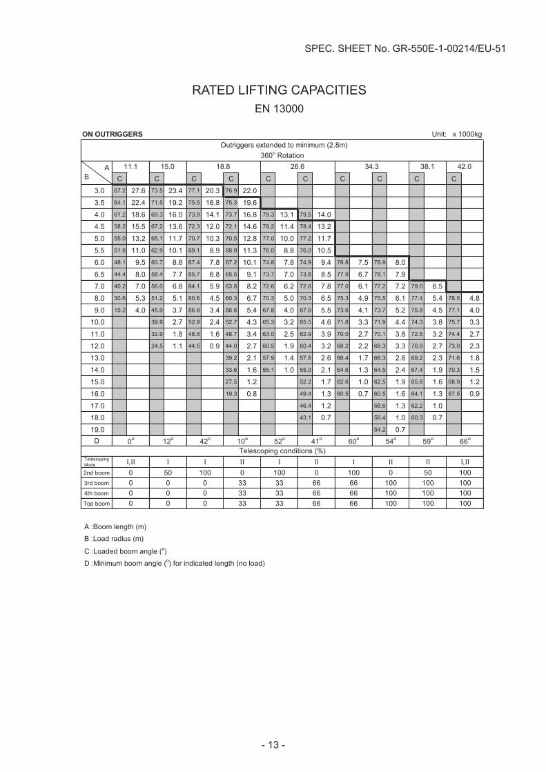
Outriggers extended to minimum (2.8m)360o Rotation
AB
42.034.326.618.815.011.1 38.1
100 0 100 0Ι
100 0ΙΙ
100500 0 0 33 33 66 66 100 1000 0 0 33 33 66 66 100
100100
0 0 0 33 33 66 66 100100
0o 12o 42o 10o
100100
Telescoping conditions (%)
0 50
66o52o 41o 60o 54o 59o

- 14 -
SPEC. SHEET No. GR-550E-1-00214/EU-51
NOTES FOR "ON OUTRIGGERS" TABLE
1. Rated lifting capacities shown in the table are based on condition that crane is set on firm levelsurface. Those above bold lines are based on crane strength and those below, on its stability.
2. Rated lifting capacities are according to EN13000.3. The mass of the hook (570 kg for 55 t capacity, 470 kg for 40 t capacity, 400 kg for 20 t
capacity, 150 kg for 5.6 t capacity), slings and all similarly used load handling devices must beconsidered as part of the load and must be deducted from the lifting capacities.
4. For rated lifting capacity of single top, reduce the rated lifting capacities of relevant boomaccording to a weight reduction for auxiliary load handling equipment. Capacities of single topshall not exceed 5,600 kg including main hook.
5. Standard number of parts of line for each boom length is as shown below. Load per lineshould not surpass 54.9 kN {5,600 kgf} for main winch and auxiliary winch.
Boom length 11.1m 11.1m to15.0m
15.0m to18.8m
18.8m to42.0m
Single topJib
Number of parts of line 11 8 6 4 1
The lifting capacity data stored in the AUTOMATIC MOMENT LIMITER (AML) is based on thestandard number of parts of line listed in the chart.Maximum lifting capacity is restricted by the number of parts of line of AUTOMATIC MOMENTLIMITER (AML).
6. The lifting capacity for over-side area differs depending on the outrigger extension width. Workwith the capacity corresponding to the extension width. The lifting capacities for over-front andover-rear areas are for “outriggers fully extended”. However, the areas (angle a) differdepending on the outrigger extension width.
Outriggers extended width 6.7m(middle)
5.5m(middle)
2.8m(minimum)
Angle a o 45 15 5

- 15 -
SPEC. SHEET No. GR-550E-1-00214/EU-51
RATED LIFTING CAPACITIESEN 13000
ON RUBBER Unit: x 1000kg
C C C C C C C C3.0 67.2 29.5 73.4 22.0 67.2 17.7 73.4 16.33.5 64.3 27.2 71.4 22.0 64.3 14.8 71.4 14.24.0 61.3 24.6 69.3 20.5 73.7 15.5 61.3 12.5 69.3 12.1 73.7 9.84.5 58.3 22.2 67.2 19.6 72.1 15.5 58.3 10.6 67.2 10.1 72.1 9.85.0 55.0 20.0 65.1 18.2 70.5 15.0 55.0 9.1 65.1 8.7 70.5 8.65.5 51.7 17.5 63.0 16.4 68.8 14.4 51.7 7.7 63.0 7.5 68.8 7.36.0 48.1 15.3 60.7 14.3 67.2 13.7 74.9 9.4 48.1 6.6 60.7 6.3 67.2 6.1 74.9 6.76.5 44.4 13.5 58.4 12.6 65.5 12.8 73.9 9.4 44.4 5.6 58.4 5.3 65.5 5.2 73.9 5.87.0 40.4 11.9 56.0 11.1 63.8 11.2 72.8 9.4 40.4 4.8 56.0 4.5 63.8 4.4 72.8 5.28.0 30.7 9.3 51.1 8.7 60.2 8.7 70.6 9.0 30.7 3.6 51.1 3.2 60.2 3.2 70.6 4.19.0 15.3 7.6 45.7 7.0 56.6 6.8 68.2 7.8 15.3 2.6 45.7 2.2 56.6 2.1 68.2 3.0
10.0 39.8 5.6 52.7 5.5 65.6 6.5 39.8 1.4 52.7 1.3 65.6 2.211.0 32.7 4.7 48.6 4.5 63.2 5.3 32.7 0.8 48.6 0.6 62.6 1.512.0 24.4 3.8 44.1 3.6 60.6 4.5 60.1 1.013.0 10.4 3.0 39.3 2.8 58.0 3.814.0 33.6 2.2 55.3 3.215.0 27.7 1.6 52.5 2.716.0 19.1 1.0 49.6 2.217.0 46.4 1.818.0 43.1 1.419.0 39.7 1.120.0 36.0 0.8
D
TelescopingMode Ι / ΙΙ Ι / ΙΙ Ι / ΙΙ Ι / ΙΙ Ι / ΙΙ Ι / ΙΙ
2nd boom 50 / 0 100 / 0 100 / 0 50 / 0 100 / 0 100 / 03rd boom 0 / 16 0 / 33 33 / 66 0 / 16 0 / 33 33 / 664th boom 0 / 16 0 / 33 33 / 66 0 / 16 0 / 33 33 / 66Top boom 0 / 16 0 / 33 33 / 66 0 / 16 0 / 33 33 / 66
A :Boom length (m)B :Load radius (m)C :Loaded boom angle (o)D :Minimum boom angle (o) for indicated length (no load)
Stationary A
B
Over Front 360o Rotation6.628.810.511.11
Telescoping conditions (%)
00
Ι,ΙΙ
18.8 26.6 11.1 15.0
0o 0o 29o 48o 58o
0
32o
000
Ι,ΙΙ
00

- 16 -
SPEC. SHEET No. GR-550E-1-00214/EU-51
RATED LIFTING CAPACITIESEN 13000
ON RUBBER Unit: x 1000kg
C C C C C C C C3.0 67.2 22.7 73.4 21.3 67.2 17.0 73.4 16.3
3.5 64.3 20.2 71.4 19.2 64.3 14.8 71.4 14.2
4.0 61.3 18.2 69.3 17.3 73.7 15.0 61.3 12.2 69.3 11.7 73.7 9.8
4.5 58.3 16.5 67.2 15.8 72.1 15.0 58.3 10.0 67.2 9.6 72.1 9.3
5.0 55.0 15.1 65.1 14.4 70.5 14.1 55.0 8.2 65.1 8.0 70.5 7.7
5.5 51.7 13.6 63.0 13.2 68.8 13.0 51.7 7.0 63.0 6.6 68.8 6.4
6.0 48.1 12.4 60.7 12.0 67.2 11.9 74.9 9.4 48.1 5.9 60.7 5.5 67.2 5.4 74.7 6.4
6.5 44.4 11.4 58.4 11.0 65.5 11.0 73.9 9.4 44.4 5.0 58.4 4.7 65.5 4.6 73.5 5.5
7.0 40.4 10.5 56.0 10.1 63.8 10.1 72.8 9.4 40.4 4.3 56.0 4.1 63.8 3.8 72.4 4.8
8.0 30.7 8.5 51.1 8.1 60.2 7.9 70.6 8.6 30.7 3.1 51.1 2.8 60.2 2.7 70.0 3.6
9.0 15.3 6.7 45.7 6.3 56.6 6.2 68.2 7.2 15.7 2.2 45.7 1.9 56.6 1.7 67.5 2.7
10.0 39.8 5.1 52.7 4.9 65.6 5.9 39.8 1.2 52.7 1.1 65.1 1.9
11.0 32.7 4.1 48.6 3.9 63.2 4.9 62.6 1.3
12.0 24.4 3.3 44.1 3.1 60.6 4.0 60.1 0.8
13.0 10.4 2.6 39.3 2.4 58.0 3.3
14.0 33.6 1.8 55.3 2.7
15.0 27.7 1.3 52.5 2.2
16.0 19.1 0.9 49.6 1.8
17.0 46.4 1.4
18.0 43.1 1.0
19.0 39.7 0.8
D
TelescopingMode ΙΙ / ΙΙΙ / ΙΙΙ / ΙΙΙ / ΙΙΙ / ΙΙΙ / Ι
2nd boom 50 / 0 100 / 0 100 / 0 50 / 0 100 / 0 100 / 03rd boom 0 / 16 0 / 33 33 / 66 0 / 16 0 / 33 33 / 664th boom 0 / 16 0 / 33 33 / 66 0 / 16 0 / 33 33 / 66Top boom 0 / 16 0 / 33 33 / 66 0 / 16 0 / 33 33 / 66
A :Boom length (m)B :Load radius (m)C :Loaded boom angle (o)D :Minimum boom angle (o) for indicated length (no load)
ΙΙ,ΙΙΙ,Ι
Creep
Telescoping conditions (%)
00
11.1 15.0 18.8
0o 36o
26.6 11.1
00
A
B
Over Front 360o Rotation
00
00
50o 59o
18.8 26.615.0
0o 34o

- 17 -
SPEC. SHEET No. GR-550E-1-00214/EU-51
NOTES FOR "ON RUBBER" TABLES
1. Rated lifting capacities shown in the table are based on condition that crane is set on firmlevel surface, with suspension lock applied. Those above bold lines are based on tirecapacity and those below, on crane stability. They are based on actual working radiiincreased by tire deformation and boom deflection.
2. Rated lifting capacities are according to EN13000.3. The mass of the hook (570 kg for 55t capacity, 470 kg for 40t capacity, 400 kg for 20t
capacity, 150 kg for 5.6t capacity), slings and all similarly used load handling devices mustbe considered as part of the load and must be deducted from the lifting capacities.
4. For rated lifting capacity of single top, reduce the rated lifting capacities of relevant boomaccording to weight reductions for auxiliary load handling equipment. Capacities of singletop shall not exceed 5,600 kg including main hook.
5. On rubber lifting with "jib" is not permitted. Maximum permissible boom length is 26.6 m.6. Creep is motion for crane not to travel more than 60 m in any 30 minute period and to travel
at the speed of less than 1.6 km/h.7. During "Creep" duties travel slowly and keep the lifting load as close to the ground as
possible, and especially avoid any abrupt steering, accelerating or braking.8. Do not operate the crane while carrying the load.9. Tires should be inflated to their correct air pressure.
Tires Air pressure29.5-25 22PR 420 kPa (4.2kgf/cm2)29.5-25 28PR 450 kPa (4.5kgf/cm2)
10. For Creep operation, set Drive select switch to "4-WHEEL(Lo)" and set gear shift lever to"1".
11. Standard number of parts of line for on tires operation should be according to the followingtable. Load per line should not surpass 54.9 kN {5,600 kgf} for main winch and auxiliarywinch.
Over Front 360o Rotation
Boom length11.1m
11.1mto
26.6m
Singletop 11.1m
11.1mto
26.6m
Singletop
6 4 1 4 4 1Number of parts of lineThe lifting capacity data stored in the AUTOMATIC MOMENT LIMITER (AML) is based onthe standard number of parts of line listed in the chart.Maximum lifting capacity is restricted by the number of parts of line of AUTOMATICMOMENT LIMITER (AML).
WORKING AREA
Without outriggers "Over front"operation should be performed within2 degrees in front of chassis.

Telescoping mode
37°
70°80°
20°
10°
0°
40°
30°
60°
45°
45°25°3.5°
42.0m
26.6m
18.8m
11.1m
34.3m
55°
18.8m Boom
26.6m Boom
34.3m Boom
42.0m Boom
42.0m Boom+9.9m Jib
42.0m Boom+17.7m Jib
50°
38.1m
38.1m Boom
42.0m
18.8m
15.0m
11.1m
26.6m
34.3m
Telescoping mode
0
5
10
15
20
25
30
35
40
45
50
55
60
0 5 10 15 20 25 30 35 40
65
15m Boom11.1m Boom
0.64m
Approx. 2.1m
Approx. 2.3m
Boom Length
NOTE:The above lifting height and boom angle are based on a straight(unladen) boom, and allowance should be made for boom deflection obtained under laden conditions. The above working range is shown on condition with outriggers fully(7.2m)extended.
Approx. 2.7m
WORKING RANGE
BOOM
JIB
SINGLE TOP
LIFT
ING
HE
IGH
T (m
)
RADIUS (m)
- 18 -
SPEC. SHEET No. GR-550E-1-00214/EU-51

DIM
EN
SIO
NS
SPEC. SHEET No. GR-550E-1-00214/EU-51
R4120
2245
1875
7200
1850
3950
2502
3315
7200 (O/R Max)6700 (O/R Mid2)5500 (O/R Mid1)2800 (O/R Min)
11100 ~ 42000
3860
17.6°
2000
14.4°
440
13695
7500
DIM
EN
SIO
NS
- 19 -
-20-
SPEC. SHEET No. GR-550E-1-00214/EU-51
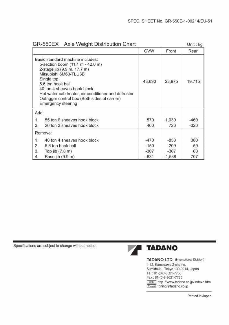
GR-550EX Axle Weight Distribution Chart Unit : kgraeRtnorFWVG
Basic standard machine includes:5-section boom (11.1 m - 42.0 m)2-stage jib (9.9 m, 17.7 m)Mitsubishi 6M60-TLU3BSingle top5.6 ton hook ball40 ton 4 sheaves hook blockHot water cab heater, air conditioner and defrosterOutrigger control box (Both sides of carrier)Emergency steering
43,690 23,975 19,715
:ddA
064-030,1075kcolbkoohsevaehs6not55.1023-027004kcolbkoohsevaehs2not02.2
:evomeR
083058-074-kcolbkoohsevaehs4not04.195902-051-llabkoohnot6.5.206763-703-)m8.7(bijpoT.3707835,1-138-)m9.9(bijesaB.4